NATURAL CIRCULATION THROUGH SINGLE NATURAL CIRCULATION THROUGH SINGLE - - ENDED ENDED EVACUATED TUBE SOLAR COLLECTORS EVACUATED TUBE SOLAR COLLECTORS Graham L. Morrison, Indra Budihardjo, Masud Behnia School of Mechanical and Manufacturing Engineering University of New South Wales, Sydney 2052 Australia
Transcript
NATURAL CIRCULATION THROUGH SINGLENATURAL CIRCULATION THROUGH SINGLE--ENDED ENDED EVACUATED TUBE SOLAR COLLECTORSEVACUATED TUBE SOLAR COLLECTORS
Graham L. Morrison, Indra Budihardjo, Masud Behnia
School of Mechanical and Manufacturing EngineeringUniversity of New South Wales, Sydney 2052
Australia
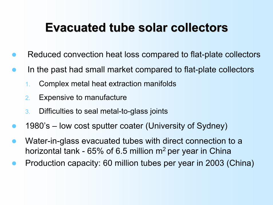
Evacuated tube solar collectorsEvacuated tube solar collectors
Reduced convection heat loss compared to flat-plate collectors
In the past had small market compared to flat-plate collectors1. Complex metal heat extraction manifolds
2. Expensive to manufacture
3. Difficulties to seal metal-to-glass joints
1980’s – low cost sputter coater (University of Sydney)
Water-in-glass evacuated tubes with direct connection to a horizontal tank - 65% of 6.5 million m2 per year in ChinaProduction capacity: 60 million tubes per year in 2003 (China)
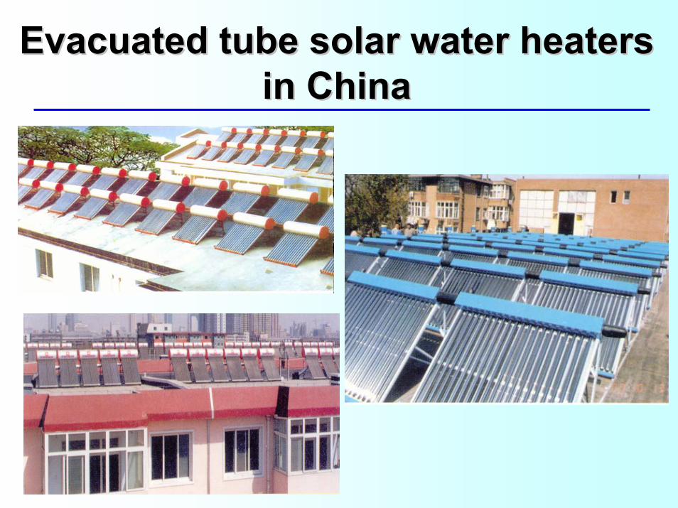
Evacuated tube solar water heaters Evacuated tube solar water heaters in Chinain China
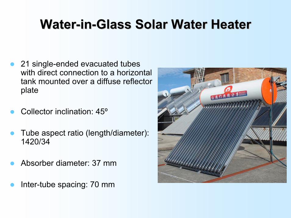
WaterWater--inin--Glass Solar Water HeaterGlass Solar Water Heater
21 single-ended evacuated tubes with direct connection to a horizontal tank mounted over a diffuse reflector plate
Collector inclination: 45º
Tube aspect ratio (length/diameter): 1420/34
Absorber diameter: 37 mm
Inter-tube spacing: 70 mm
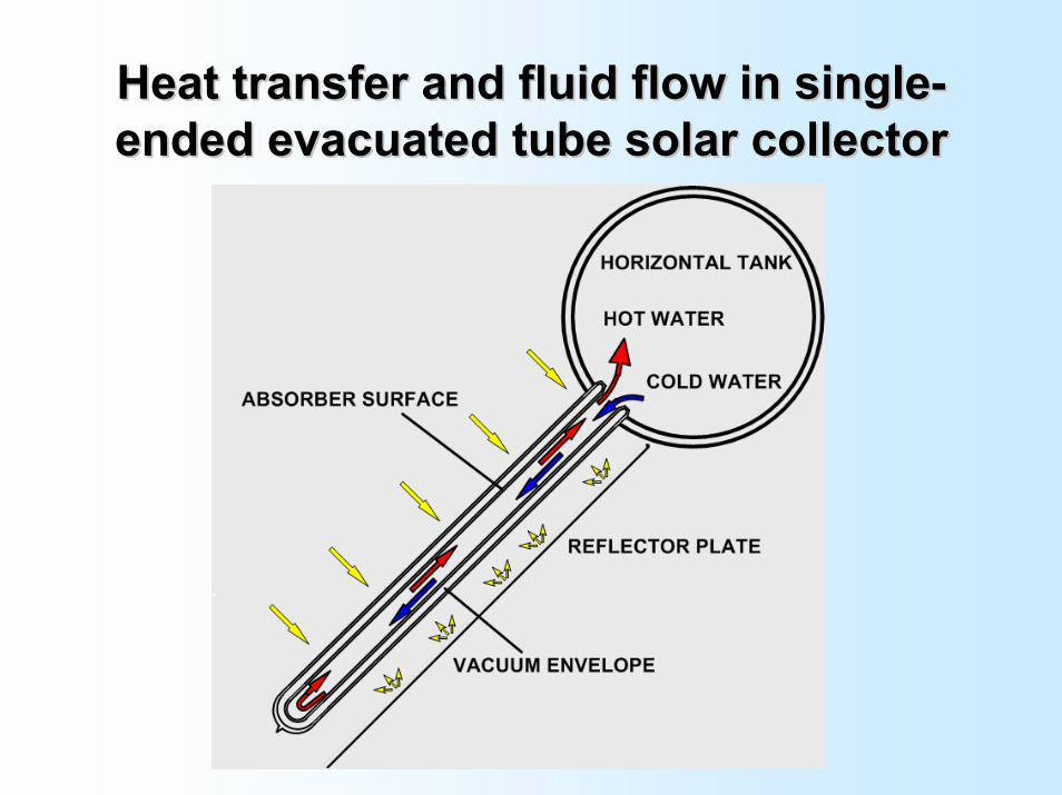
Heat transfer and fluid flow in singleHeat transfer and fluid flow in single--ended evacuated tube solar collectorended evacuated tube solar collector
Performance EvaluationPerformance Evaluation
Modelling of the system requires data on
Heat loss of the storage tank
Optical efficiency of the collector
Heat loss of the evacuated tubes and efficiency equation
Natural circulation flow rate through the tubes
Circulation flow rate through Circulation flow rate through single ended evacuated tubessingle ended evacuated tubes
Collector flow rate determines the degree of mixing in the storage tank, in particular for systems adopting ‘direct’ circulation
Thermal stratification in the storage tank influences solar water heater performance
High thermal stratification results in a higher fraction of tank volume that is available for domestic use (at delivery load temperature)
Lower temperature water at tank bottom circulates through the collector – higher efficiency
Tank temperature – density gradient and viscosity of water varies significantly over collector operating temperatures
Collector inclination – determines the components of gravity driven bouyancy in the axial direction (primary circulation) and radial direction (secondary circulation)
Tube length-diameter ratio
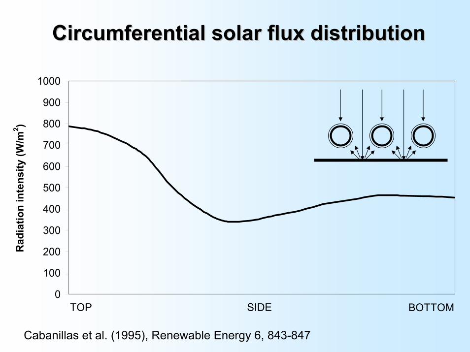
Circumferential solar flux distribution (reflector shape)
*presented at ISES Solar World Congress 2003 Gothenborg & Solar Energy V76,135
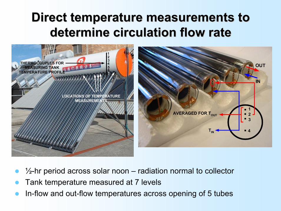
Direct temperature measurements to Direct temperature measurements to determine circulation flow ratedetermine circulation flow rate
½-hr period across solar noon – radiation normal to collectorTank temperature measured at 7 levels In-flow and out-flow temperatures across opening of 5 tubes
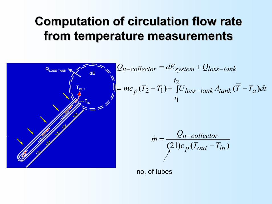
Computation of circulation flow rate Computation of circulation flow rate from temperature measurementsfrom temperature measurements
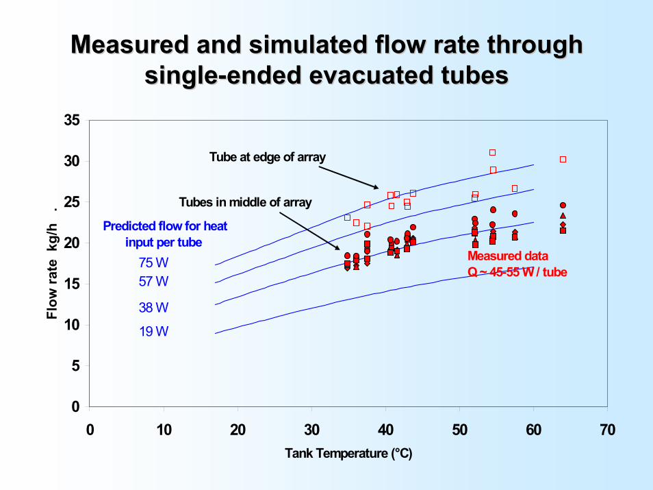
Measured and simulated flow rate through Measured and simulated flow rate through singlesingle--ended evacuated tubesended evacuated tubes
0
5
10
15
20
25
30
35
0 10 20 30 40 50 60 70Tank Temperature (°C)
Flow
rate
kg/
h .
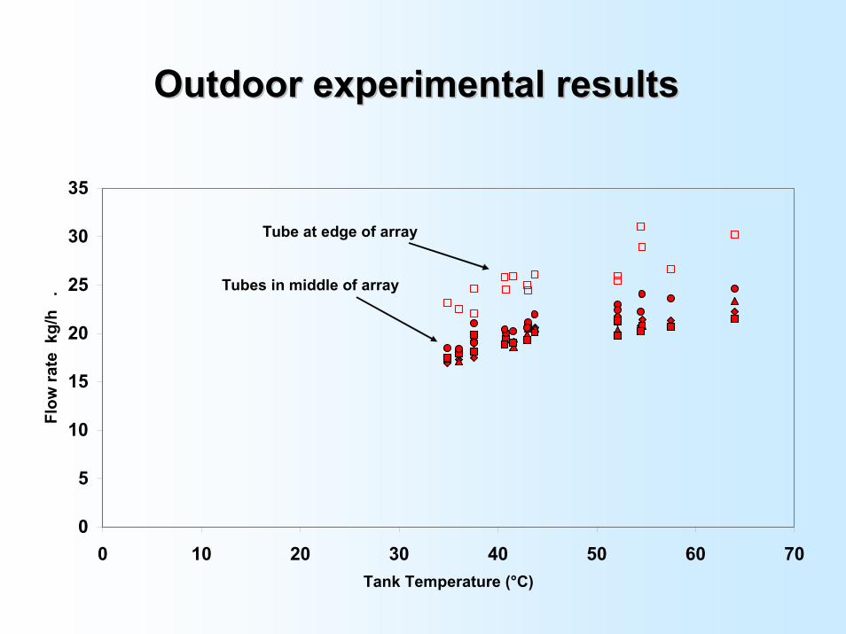
Tubes in middle of array
Tube at edge of array
75 W
19 W
38 W
57 W
Measured dataQ ~ 45-55 W / tube
Predicted flow for heat input per tube
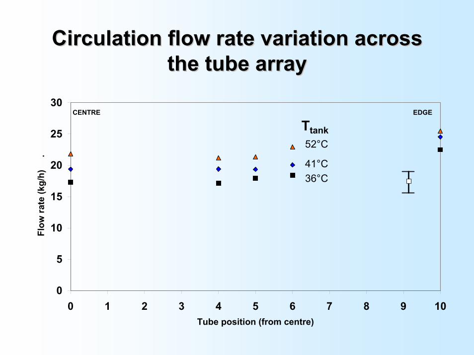
Circulation flow rate variation across Circulation flow rate variation across the tube arraythe tube array
0
5
10
15
20
25
30
0 1 2 3 4 5 6 7 8 9 10Tube position (from centre)
Flo
w ra
te (k
g/h)
.
CENTRE EDGE
36°C41°C
52°C
Ttank
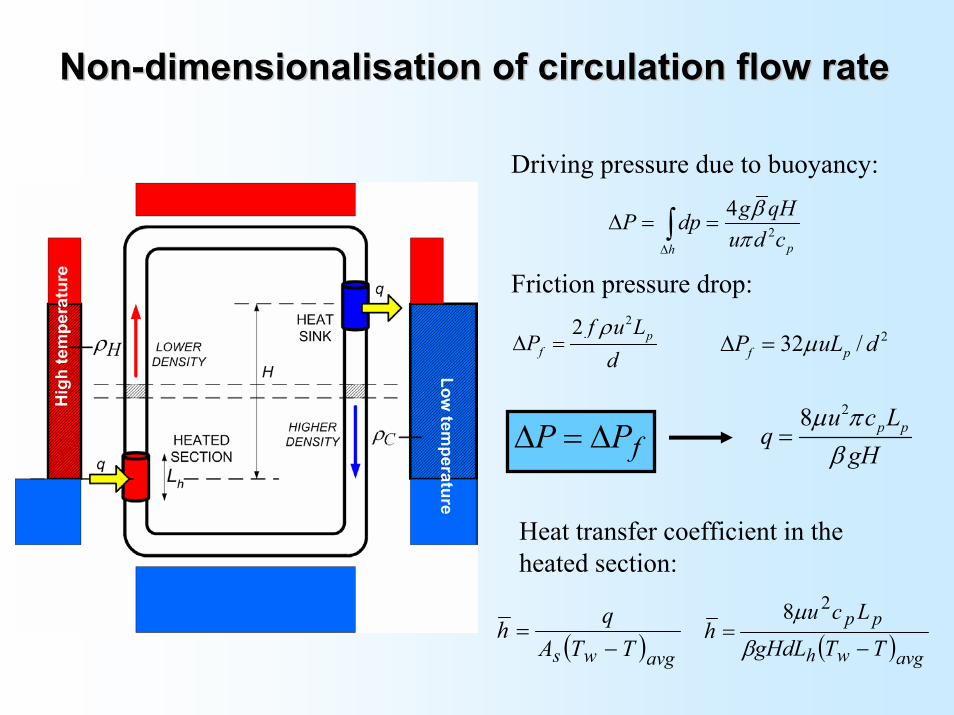
NonNon--dimensionalisation of circulation flow ratedimensionalisation of circulation flow rate
Driving pressure due to buoyancy:
2
4
ph
g qHP dpu d cβ
π∆
∆ = =∫
Friction pressure drop:22 p
f
f u LP
dρ
∆ = 232 /f pP uL dµ∆ =
28 p pu c Lq
gHµ πβ
=fPP ∆=∆
Heat transfer coefficient in the heated section:
( )avgws TTAqh−
= ( )avgwh
pp
TTgHdLLcu
h−
=β
µ 28
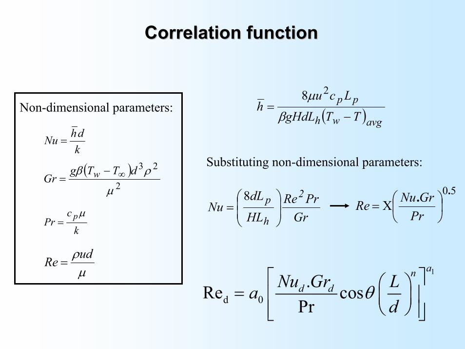
Correlation functionCorrelation function
( )avgwh
pp
TTgHdLLcu
h−
=β
µ 28
kdhNu =
( )2
23
µ
ρβ dTTgGr w ∞−
=
k
cPr pµ=
µρudRe =
Non-dimensional parameters:
Substituting non-dimensional parameters:
50..
Χ=PrGrNuRe
GrPrRe
HL
dLNu
2
h
p
=
8
1
d 0.Re cos
Pr
and dNu Gr La
dθ
=
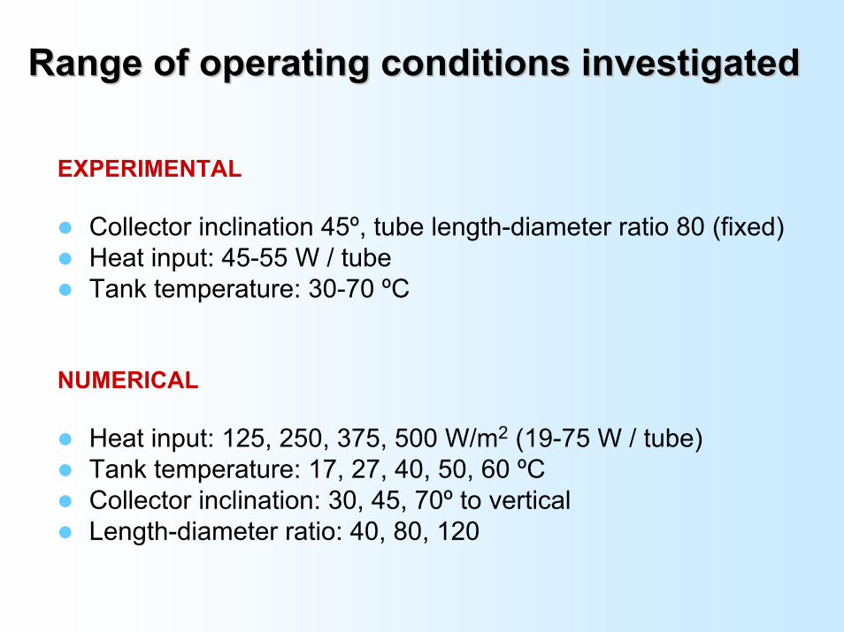
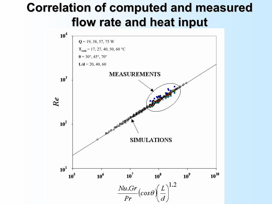
Correlation of computed and measured Correlation of computed and measured flow rate and heat inputflow rate and heat input
Q = 19, 38, 57, 75 W
Ttank = 17, 27, 40, 50, 60 °C
θ = 30°, 45°, 70°
L/d = 20, 40, 60
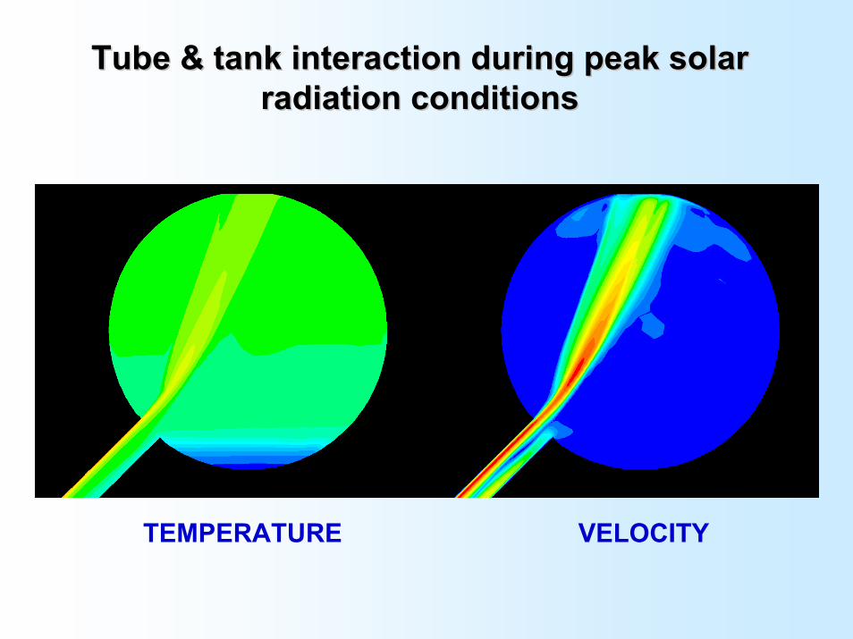
Tube & tank interaction during peak solar Tube & tank interaction during peak solar radiation conditionsradiation conditions
TEMPERATURE VELOCITY
Concluding remarksConcluding remarksHigh circulation flow rate through water-in-glass evacuated tubes
Flow rate across the tube array is uniform, except for tubes near the edge of the array (perhaps!)
New flow rate correlation developed for evacuated tubes mounted over a diffuse reflector
Control of flow rate to promote tank thermal stratification may improve system performance
Energy delivery of good quality evacuated tubes is not as sensitive as flat plate collectors to tank stratification, however recovery rate of delivered water temperature is still influenced by stratification