Natural Gas Solutions Applications, Features, Specifications aerospace climate control electromechanical filtration fluid & gas handling hydraulics pneumatics process control sealing & shielding
Transcript
Natural Gas SolutionsApplications, Features, Specifi cations
aerospaceclimate controlelectromechanicalfiltrationfluid & gas handlinghydraulicspneumaticsprocess controlsealing & shielding
New developments and improvements are constantly being made to increase the use of this clean burning, effi cient fuel.
Natural gas comes from underground, and thousands of kilometres of pipeline exist in Europe to transport the gas. Compressor stations located along the length of pipeline move the gas from the wellhead to consumer distribution points.
Why Filter Natural Gas?
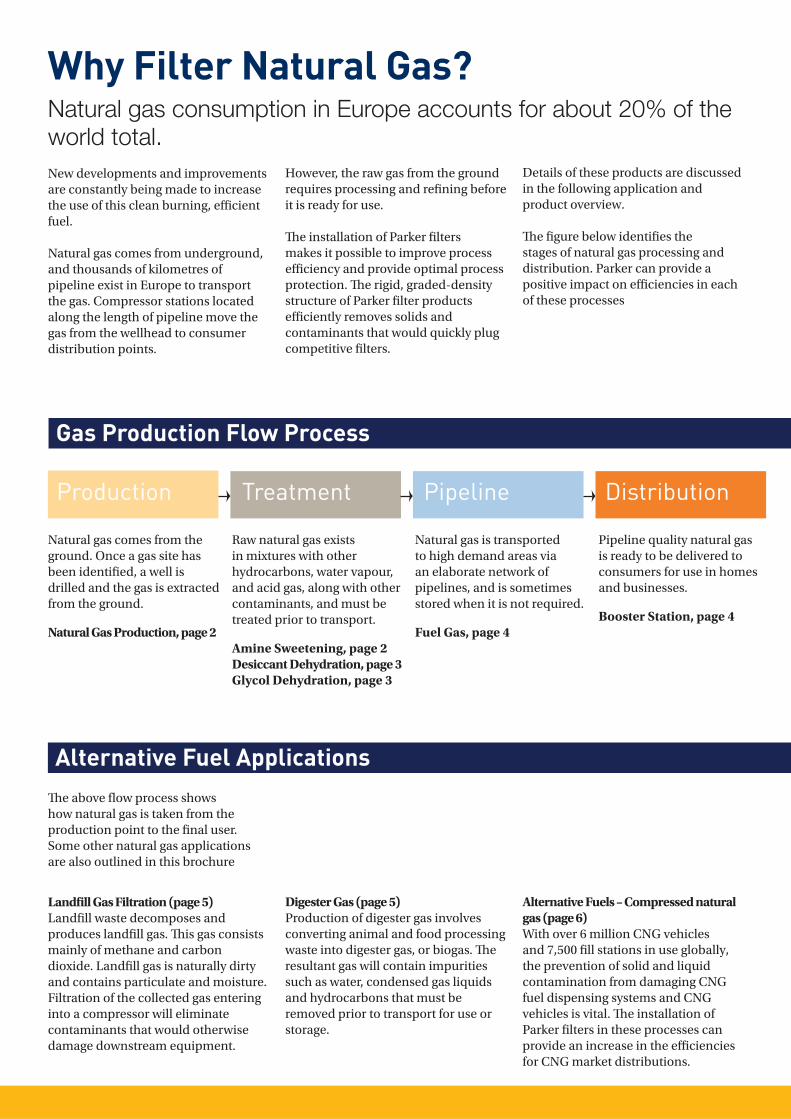
Production Treatment Pipeline Distribution
Gas Production Flow Process
Natural gas comes from the ground. Once a gas site has been identifi ed, a well is drilled and the gas is extracted from the ground.
Natural Gas Production, page 2
Alternative Fuel ApplicationsTh e above fl ow process shows how natural gas is taken from the production point to the fi nal user. Some other natural gas applications are also outlined in this brochure
Raw natural gas exists in mixtures with other hydrocarbons, water vapour, and acid gas, along with other contaminants, and must be treated prior to transport.
Natural gas is transported to high demand areas via an elaborate network of pipelines, and is sometimes stored when it is not required.
Fuel Gas, page 4
Pipeline quality natural gas is ready to be delivered to consumers for use in homes and businesses.
Booster Station, page 4
However, the raw gas from the ground requires processing and refi ning before it is ready for use.
Th e installation of Parker fi lters makes it possible to improve process effi ciency and provide optimal process protection. Th e rigid, graded-density structure of Parker fi lter products effi ciently removes solids and contaminants that would quickly plug competitive fi lters.
Natural gas consumption in Europe accounts for about 20% of the world total.
Details of these products are discussed in the following application and product overview.
Th e fi gure below identifi es the stages of natural gas processing and distribution. Parker can provide a positive impact on effi ciencies in each of these processes
Landfi ll Gas Filtration (page 5) Landfi ll waste decomposes and produces landfi ll gas. Th is gas consists mainly of methane and carbon dioxide. Landfi ll gas is naturally dirty and contains particulate and moisture. Filtration of the collected gas entering into a compressor will eliminate contaminants that would otherwise damage downstream equipment.
Digester Gas (page 5)Production of digester gas involves converting animal and food processing waste into digester gas, or biogas. Th e resultant gas will contain impurities such as water, condensed gas liquids and hydrocarbons that must be removed prior to transport for use or storage.
Alternative Fuels – Compressed natural gas (page 6)With over 6 million CNG vehicles and 7,500 fi ll stations in use globally, the prevention of solid and liquid contamination from damaging CNG fuel dispensing systems and CNG vehicles is vital. Th e installation of Parker fi lters in these processes can provide an increase in the effi ciencies for CNG market distributions.
Amine Sweetening
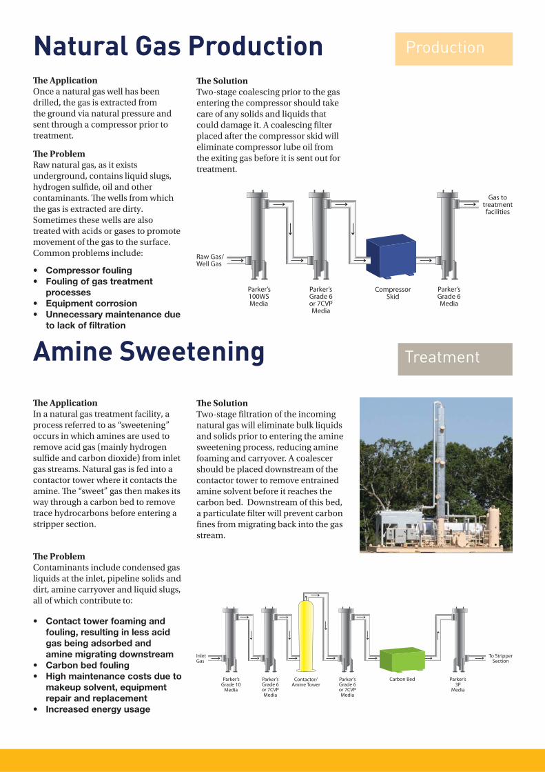
Th e ApplicationIn a natural gas treatment facility, a process referred to as “sweetening” occurs in which amines are used to remove acid gas (mainly hydrogen sulfi de and carbon dioxide) from inlet gas streams. Natural gas is fed into a contactor tower where it contacts the amine. Th e “sweet” gas then makes its way through a carbon bed to remove trace hydrocarbons before entering a stripper section.
Th e ProblemContaminants include condensed gas liquids at the inlet, pipeline solids and dirt, amine carryover and liquid slugs, all of which contribute to: • Contact tower foaming and fouling, resulting in less acid gas being adsorbed and amine migrating downstream• Carbon bed fouling • High maintenance costs due to makeup solvent, equipment repair and replacement • Increased energy usage
Th e SolutionTwo-stage fi ltration of the incoming natural gas will eliminate bulk liquids and solids prior to entering the amine sweetening process, reducing amine foaming and carryover. A coalescer should be placed downstream of the contactor tower to remove entrained amine solvent before it reaches the carbon bed. Downstream of this bed, a particulate fi lter will prevent carbon fi nes from migrating back into the gas stream.
Natural Gas ProductionTh e ApplicationOnce a natural gas well has been drilled, the gas is extracted from the ground via natural pressure and sent through a compressor prior to treatment.
Th e ProblemRaw natural gas, as it exists underground, contains liquid slugs, hydrogen sulfi de, oil and other contaminants. Th e wells from which the gas is extracted are dirty.Sometimes these wells are also treated with acids or gases to promote movement of the gas to the surface. Common problems include:
• Compressor fouling• Fouling of gas treatment processes• Equipment corrosion• Unnecessary maintenance due to lack of fi ltration
Th e SolutionTwo-stage coalescing prior to the gas entering the compressor should take care of any solids and liquids that could damage it. A coalescing fi lter placed after the compressor skid will eliminate compressor lube oil from the exiting gas before it is sent out for treatment.
Production
Treatment
Parker’s Parker’s Parker’s
Parker’s Parker’sParker’s Parker’s
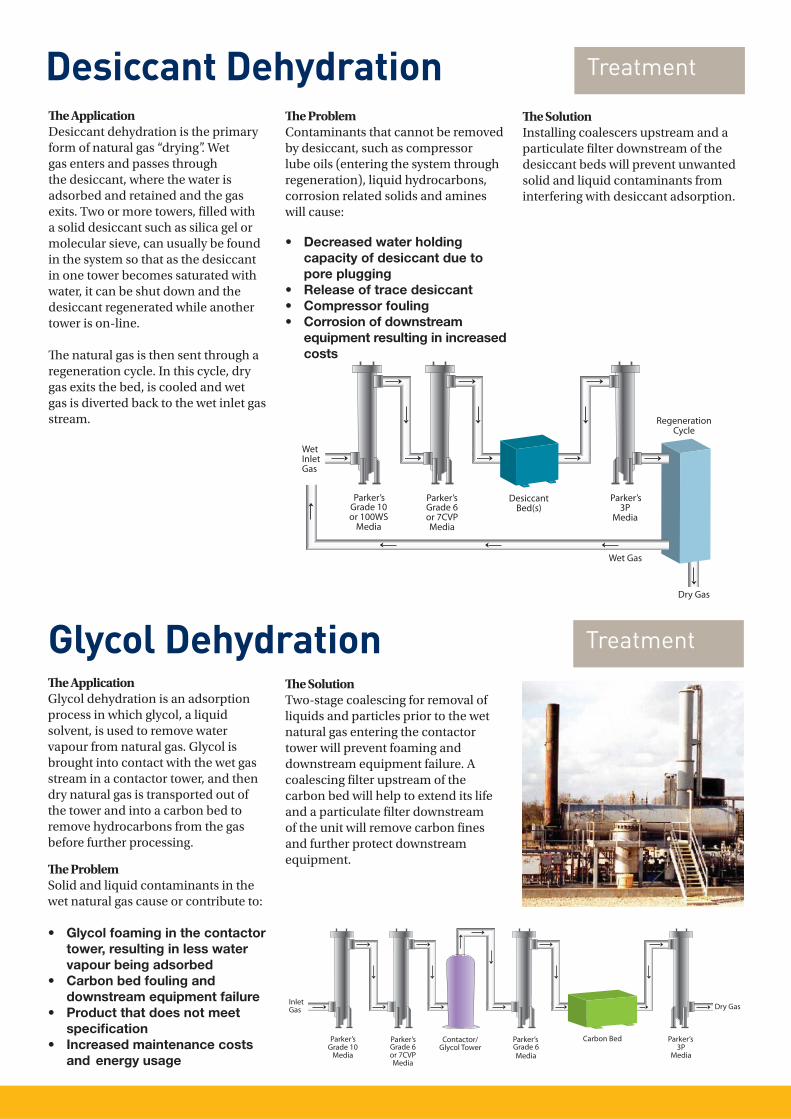
Desiccant DehydrationTh e ApplicationDesiccant dehydration is the primary form of natural gas “drying”. Wet gas enters and passes through the desiccant, where the water is adsorbed and retained and the gas exits. Two or more towers, fi lled with a solid desiccant such as silica gel or molecular sieve, can usually be found in the system so that as the desiccant in one tower becomes saturated with water, it can be shut down and the desiccant regenerated while another tower is on-line.
Th e natural gas is then sent through a regeneration cycle. In this cycle, dry gas exits the bed, is cooled and wet gas is diverted back to the wet inlet gas stream.
Th e ProblemContaminants that cannot be removed by desiccant, such as compressor lube oils (entering the system through regeneration), liquid hydrocarbons, corrosion related solids and amines will cause:
• Decreased water holding capacity of desiccant due to pore plugging• Release of trace desiccant• Compressor fouling• Corrosion of downstream
equipment resulting in increased costs
Th e SolutionInstalling coalescers upstream and a particulate fi lter downstream of the desiccant beds will prevent unwanted solid and liquid contaminants from interfering with desiccant adsorption.
Treatment
Glycol DehydrationTh e ApplicationGlycol dehydration is an adsorption process in which glycol, a liquid solvent, is used to remove water vapour from natural gas. Glycol is brought into contact with the wet gas stream in a contactor tower, and then dry natural gas is transported out of the tower and into a carbon bed to remove hydrocarbons from the gas before further processing.
Th e ProblemSolid and liquid contaminants in the wet natural gas cause or contribute to:
• Glycol foaming in the contactor tower, resulting in less water vapour being adsorbed• Carbon bed fouling and downstream equipment failure • Product that does not meet specifi cation• Increased maintenance costs and energy usage
Th e SolutionTwo-stage coalescing for removal of liquids and particles prior to the wet natural gas entering the contactor tower will prevent foaming and downstream equipment failure. A coalescing fi lter upstream of the carbon bed will help to extend its life and a particulate fi lter downstream of the unit will remove carbon fi nes and further protect downstream equipment.
Treatment
Parker’s Parker’s Parker’s
Parker’s Parker’s Parker’s Parker’s
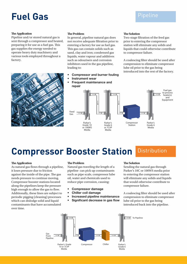
Fuel Gas Th e ApplicationPipeline and/or stored natural gas is sent through a compressor and heated, preparing it for use as a fuel gas. Th is gas supplies the energy needed to operate heavy duty machinery and various tools employed throughout a factory.
Th e ProblemIn general, pipeline natural gas does not receive adequate fi ltration prior to entering a factory for use as fuel gas.Th is gas can contain solids such as sand, clay and iron; condensed gas liquids, water vapour and additives such as odourisers and corrosion inhibitors used in the gas pipeline, leading to:
• Compressor and burner fouling• Instrument wear• Frequent maintenance and repair
Th e SolutionTwo-stage fi ltration of the feed gas prior to entering the compressor station will eliminate any solids and liquids that could otherwise contribute to compressor failure.
A coalescing fi lter should be used after compression to eliminate compressor lube oil prior to the gas being introduced into the rest of the factory.
Compressor Booster Station Th e ApplicationAs natural gas fl ows through a pipeline, it loses pressure due to friction against the inside of the pipe. Th e gas needs pressure to continue moving. Compressor booster stations located along the pipelines keep the pressure high enough to allow the gas to fl ow. Additionally, these lines are subject to periodic pigging (cleaning) processes which can dislodge solid and liquid contaminants that have accumulated over time.
Th e ProblemNatural gas traveling the length of a pipeline can pick up contaminants such as pipe scale, compressor lube oil, water and chemicals used to reduce pipe corrosion, causing:
• Compressor damage• Chiller coil damage• Increased pipeline maintenance• Signifi cant decrease in gas fl ow
Th e SolutionSending the natural gas through Parker’s 10C or 100WS media prior to entering the compressor station will eliminate any solids and liquids that would otherwise contribute to compressor failure.
A coalescing fi lter should be used after compression to eliminate compressor lube oil prior to the gas being introduced back into the pipeline.
Pipeline
Distribution
Parker’s Parker’s Parker’s
Parker’s Parker’s
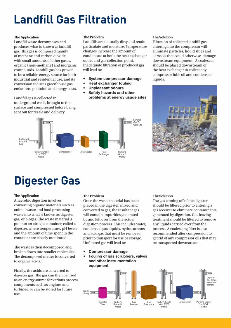
Landfi ll Gas FiltrationTh e ApplicationLandfi ll waste decomposes and produces what is known as landfi ll gas. Th is gas is composed mainly of methane and carbon dioxide, with small amounts of other gases, organic (non-methane) and inorganic compounds. Landfi ll gas has proven to be a reliable energy source for both industrial and residential use, and its conversion reduces greenhouse gas emissions, pollution and energy costs.
Landfi ll gas is collected in underground wells, brought to the surface and compressed before being sent out for resale and delivery.
Th e ProblemLandfi lls are naturally dirty and retain particulate and moisture. Temperature changes increase the amount of condensate at both the heat exchanger outlet and gas collection point. Inadequate fi ltration of produced gas will lead to:
• System compressor damage• Heat exchanger fouling• Unpleasant odours• Safety hazards and other problems at energy usage sites
Th e SolutionFiltration of collected landfi ll gas entering into the compressor will eliminate particles, liquid slugs and aerosols that could otherwise damage downstream equipment. A coalescer should be placed downstream of the heat exchanger to collect any compressor lube oil and condensed liquids.
Digester GasTh e ApplicationAnaerobic digestion involves converting organic materials such as animal waste and food processing waste into what is known as digester gas, or biogas. Th e waste material is put into an airtight container, called a digester, where temperature, pH levels and the amount of time spent in the container are closely monitored.
Th e waste is then decomposed and broken down into smaller molecules. Th e decomposed matter is converted to organic acids.
Finally, the acids are converted to digester gas. Th e gas can then be used as an energy source for various process components such as engines and turbines, or can be stored for future use.
Th e ProblemOnce the waste material has been placed in the digester, mixed and converted to gas, the resultant gas will contain impurities generated by and left over from the actual digestion process. Th is includes water, condensed gas liquids, hydrocarbons and acid gas that must be removed prior to transport for use or storage. Unfi ltered gas will lead to:
• Compressor damage • Fouling of gas scrubbers, valves
and other instrumentation equipment
Th e SolutionTh e gas coming off of the digester should be fi ltered prior to entering a gas receiver to eliminate contaminants generated by digestion. Gas leaving treatment should be fi ltered to remove any liquids carried over from the process. A coalescing fi lter is also recommended after compression to get rid of any compressor oils that may be transported downstream.
Parker’s Parker’s
Parker’s Parker’s Parker’s
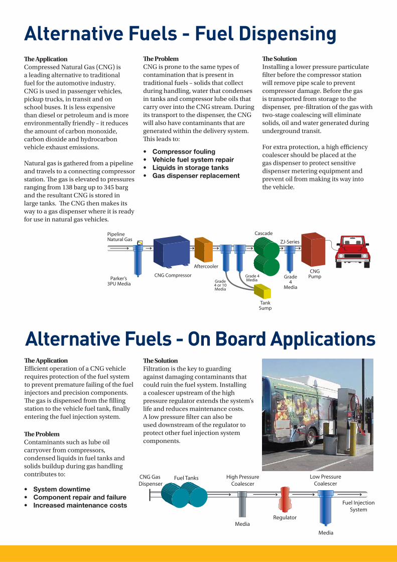
Alternative Fuels - Fuel DispensingTh e ApplicationCompressed Natural Gas (CNG) is a leading alternative to traditional fuel for the automotive industry. CNG is used in passenger vehicles, pickup trucks, in transit and on school buses. It is less expensive than diesel or petroleum and is more environmentally friendly – it reduces the amount of carbon monoxide, carbon dioxide and hydrocarbon vehicle exhaust emissions.
Natural gas is gathered from a pipeline and travels to a connecting compressor station. Th e gas is elevated to pressures ranging from 138 barg up to 345 barg and the resultant CNG is stored in large tanks. Th e CNG then makes its way to a gas dispenser where it is ready for use in natural gas vehicles.
Th e ProblemCNG is prone to the same types of contamination that is present in traditional fuels – solids that collect during handling, water that condenses in tanks and compressor lube oils that carry over into the CNG stream. During its transport to the dispenser, the CNG will also have contaminants that are generated within the delivery system. Th is leads to:
• Compressor fouling • Vehicle fuel system repair• Liquids in storage tanks• Gas dispenser replacement
Th e ApplicationEffi cient operation of a CNG vehicle requires protection of the fuel system to prevent premature failing of the fuel injectors and precision components. Th e gas is dispensed from the fi lling station to the vehicle fuel tank, fi nally entering the fuel injection system.
Alternative Fuels - On Board Applications
Th e ProblemContaminants such as lube oil carryover from compressors, condensed liquids in fuel tanks and solids buildup during gas handling contributes to:
• System downtime• Component repair and failure• Increased maintenance costs
Th e SolutionFiltration is the key to guarding against damaging contaminants that could ruin the fuel system. Installing a coalescer upstream of the high pressure regulator extends the system’s life and reduces maintenance costs. A low pressure fi lter can also be used downstream of the regulator to protect other fuel injection system components.
Th e SolutionInstalling a lower pressure particulate fi lter before the compressor station will remove pipe scale to prevent compressor damage. Before the gas is transported from storage to the dispenser, pre-fi ltration of the gas with two-stage coalescing will eliminate solids, oil and water generated during underground transit.
For extra protection, a high effi ciency coalescer should be placed at the gas dispenser to protect sensitive dispenser metering equipment and prevent oil from making its way into the vehicle.
Parker’s
ZJ-Series
CNG Gas Dispenser
High PressureCoalescer
Low PressureCoalescer
Fuel InjectionSystem
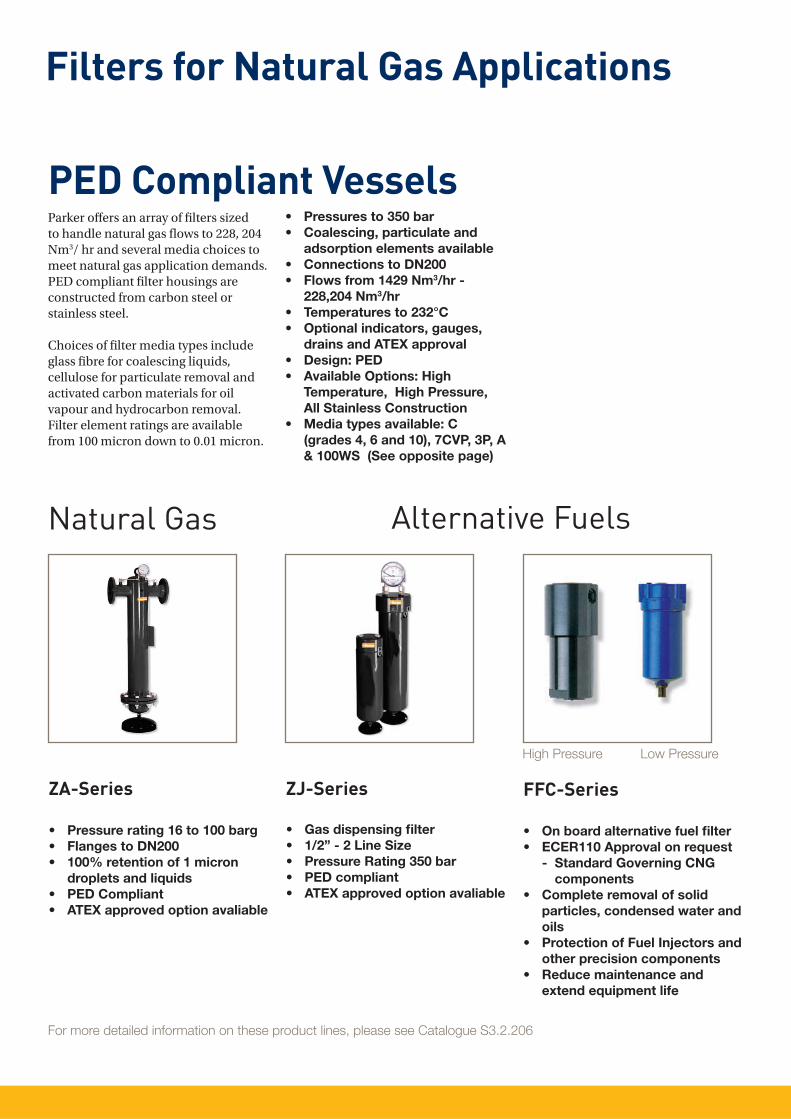
Filters for Natural Gas Applications
Parker off ers an array of fi lters sized to handle natural gas fl ows to 228, 204 Nm3/ hr and several media choices to meet natural gas application demands. PED compliant fi lter housings are constructed from carbon steel or stainless steel.
Choices of fi lter media types include glass fi bre for coalescing liquids, cellulose for particulate removal and activated carbon materials for oil vapour and hydrocarbon removal. Filter element ratings are available from 100 micron down to 0.01 micron.
• Pressures to 350 bar• Coalescing, particulate and adsorption elements available• Connections to DN200• Flows from 1429 Nm3/hr - 228,204 Nm3/hr• Temperatures to 232°C• Optional indicators, gauges, drains and ATEX approval• Design: PED• Available Options: High Temperature, High Pressure, All Stainless Construction• Media types available: C (grades 4, 6 and 10), 7CVP, 3P, A
& 100WS (See opposite page)
ZJ-SeriesZA-Series
• Pressure rating 16 to 100 barg• Flanges to DN200• 100% retention of 1 micron droplets and liquids • PED Compliant• ATEX approved option avaliable
• Gas dispensing fi lter• 1/2” - 2 Line Size• Pressure Rating 350 bar• PED compliant• ATEX approved option avaliable
For more detailed information on these product lines, please see Catalogue S3.2.206
PED Compliant Vessels
FFC-Series
• On board alternative fuel fi lter• ECER110 Approval on request - Standard Governing CNG
components• Complete removal of solid particles, condensed water and oils• Protection of Fuel Injectors and other precision components• Reduce maintenance and extend equipment life
Alternative FuelsNatural Gas
High Pressure Low Pressure
Filtration Media
Media type 100WSAir Flow: Inside to Outside
Th is rolled stainless steel mesh element has two metal retainers with rolled mesh steel in between. It is an extremely robust design. Th is media is used for the reduction and elimination of excess liquids in gas streams.
Excellent pre-fi ltration for coalescing grades 6 and 10 when extreme quantities of liquid contaminants are present.
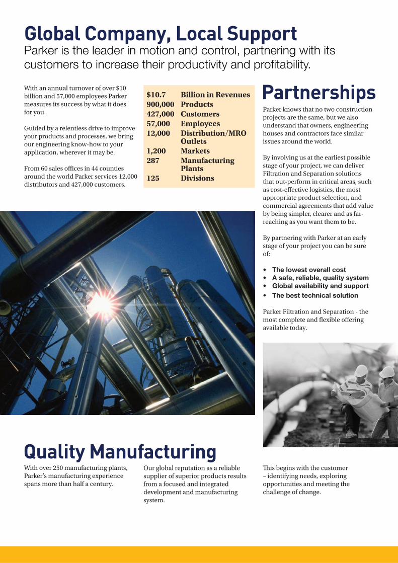
Media type C/QAvailable in grades 4, 6 or 10Air Flow: Inside to Outside
Th is coalescing element is composed of an outer layer epoxy saturated, borosilicate glass micro-fi bre tube. Type Q has a pleated cellulose inner layer as a built-in prefi lter. Th is element is metal retained for added strength, and includes a synthetic fabric safety layer.
Grade 4 fi lters are very high effi ciency coalescers. Th ey are used for elevated pressures or lighter weight gases.
Grade 6 fi lters are used when “total removal of liquid aerosols and suspended fi nes” is required. Due to its overall performance characteristics, this grade is most often recommended.
Grade 10 fi lters are used as prefi lters for grade 6 to remove gross amounts of liquid aerosols or tenacious aerosols which are diffi cult to drain.
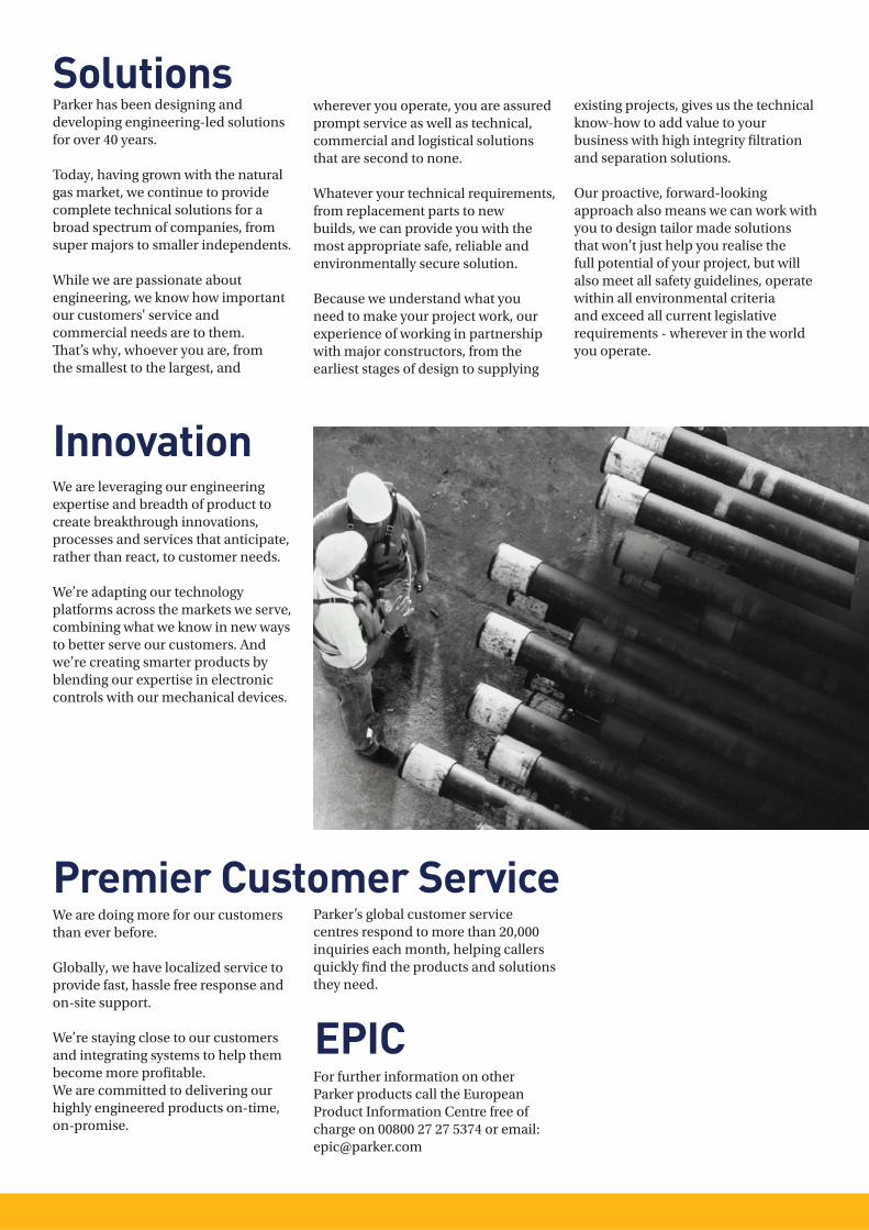
Media type 3PAir Flow: Outside to Inside
3P Particulate interceptor elements are used where very high dirt holding capacity and relatively fi ne pore structure are required.
Th is pleated element is constructed of pleated cellulose with a 3 micron rating.
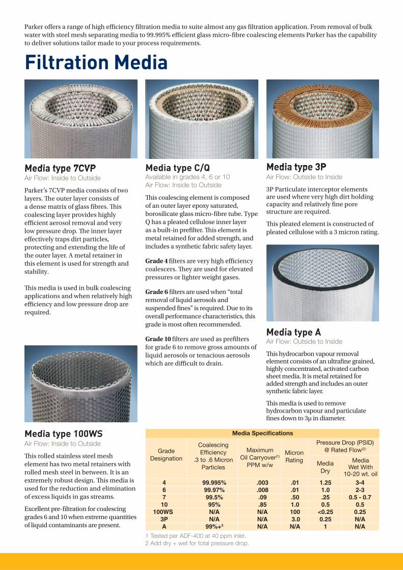
Media type 7CVPAir Flow: Inside to Outside
Parker’s 7CVP media consists of two layers. Th e outer layer consists of a dense matrix of glass fi bres. Th is coalescing layer provides highly effi cient aerosol removal and very low pressure drop. Th e inner layer eff ectively traps dirt particles, protecting and extending the life of the outer layer. A metal retainer in this element is used for strength and stability.
Th is media is used in bulk coalescing applications and when relatively high effi ciency and low pressure drop are required.
Parker off ers a range of high effi ciency fi ltration media to suite almost any gas fi ltration application. From removal of bulk water with steel mesh separating media to 99.995% effi cient glass micro-fi bre coalescing elements Parker has the capability to deliver solutions tailor made to your process requirements.
1 Tested per ADF-400 at 40 ppm inlet. 2 Add dry + wet for total pressure drop.
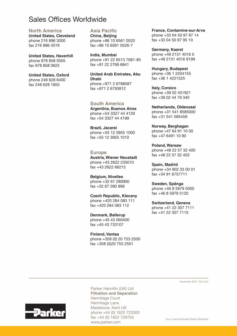
Media type AAir Flow: Outside to Inside
Th is hydrocarbon vapour removal element consists of an ultrafi ne grained, highly concentrated, activated carbon sheet media. It is metal retained for added strength and includes an outer synthetic fabric layer.
Th is media is used to remove hydrocarbon vapour and particulate fi nes down to 3µ in diameter.
Parker knows that no two construction projects are the same, but we also understand that owners, engineering houses and contractors face similar issues around the world.
By involving us at the earliest possible stage of your project, we can deliver Filtration and Separation solutions that out-perform in critical areas, such as cost-eff ective logistics, the most appropriate product selection, and commercial agreements that add value by being simpler, clearer and as far-reaching as you want them to be.
By partnering with Parker at an early stage of your project you can be sure of:
• The lowest overall cost• A safe, reliable, quality system• Global availability and support• The best technical solution
Parker Filtration and Separation - the most complete and fl exible off ering available today.
Global Company, Local SupportParker is the leader in motion and control, partnering with its customers to increase their productivity and profi tability.
With an annual turnover of over $10 billion and 57,000 employees Parker measures its success by what it does for you.
Guided by a relentless drive to improve your products and processes, we bring our engineering know-how to your application, wherever it may be.
From 60 sales offi ces in 44 counties around the world Parker services 12,000 distributors and 427,000 customers.
Quality ManufacturingWith over 250 manufacturing plants, Parker’s manufacturing experience spans more than half a century.
Partnerships$10.7 Billion in Revenues900,000 Products427,000 Customers57,000 Employees12,000 Distribution/MRO
Outlets1,200 Markets287 Manufacturing
Plants125 Divisions
Our global reputation as a reliable supplier of superior products results from a focused and integrated development and manufacturing system.
Th is begins with the customer – identifying needs, exploring opportunities and meeting the challenge of change.
SolutionsParker has been designing and developing engineering-led solutions for over 40 years.
Today, having grown with the natural gas market, we continue to provide complete technical solutions for a broad spectrum of companies, from super majors to smaller independents.
While we are passionate about engineering, we know how important our customers' service and commercial needs are to them. Th at’s why, whoever you are, from the smallest to the largest, and
wherever you operate, you are assured prompt service as well as technical, commercial and logistical solutions that are second to none.
Whatever your technical requirements, from replacement parts to new builds, we can provide you with the most appropriate safe, reliable and environmentally secure solution.
Because we understand what you need to make your project work, our experience of working in partnership with major constructors, from the earliest stages of design to supplying
existing projects, gives us the technical know-how to add value to your business with high integrity fi ltration and separation solutions.
Our proactive, forward-looking approach also means we can work with you to design tailor made solutions that won't just help you realise the full potential of your project, but will also meet all safety guidelines, operate within all environmental criteria and exceed all current legislative requirements - wherever in the world you operate.
Premier Customer Service
InnovationWe are leveraging our engineering expertise and breadth of product to create breakthrough innovations, processes and services that anticipate, rather than react, to customer needs.
We’re adapting our technology platforms across the markets we serve, combining what we know in new ways to better serve our customers. And we’re creating smarter products by blending our expertise in electronic controls with our mechanical devices.
We are doing more for our customers than ever before.
Globally, we have localized service to provide fast, hassle free response and on-site support.
We’re staying close to our customers and integrating systems to help them become more profi table. We are committed to delivering our highly engineered products on-time, on-promise.
Parker’s global customer service centres respond to more than 20,000 inquiries each month, helping callers quickly fi nd the products and solutions they need.
EPICFor further information on other Parker products call the European Product Information Centre free of charge on 00800 27 27 5374 or email: [email protected]
Your Local Authorized Parker Distributor
Parker Hannifi n (UK) LtdFiltration and Separation Hermitage CourtHermitage LaneMaidstone, Kent UKphone +44 (0) 1622 723300fax +44 (0) 1622 728703www.parker.com
North AmericaUnited States, Clevelandphone 216 896 3000fax 216 896 4019
United States, Haverhillphone 978 858 0505fax 978 858 0625
United States, Oxfordphone 248 628 6400fax 248 628 1850