171
1 Prepared by // Eng. Ahmed Mohamed Shoman
| Date post: | 01-Nov-2014 |
| Category: |
Technology |
| Upload: | ahmed-shoman |
| View: | 36 times |
| Download: | 3 times |
11Prepared by // Eng. Ahmed Mohamed Shoman

2
Content• Definitions of Frequently Used Parameters in Natural Gas
Industry.
• Introduction for natural gas.1. Natural Gas Terminology. 2. Natural Gas Formation.3. Natural Gas Composition.4. Natural Gas Properties.5. Natural Gas Phase Behavior..
• Natural Gas Conditioning.• Field Separation.• Gas Sweetening.• Gas Dehydration.
Sweetening /Dehydration Trouble Shooting (Amine & Glycol Unit).
– Gas is not Sweet– Amine solution not regenerated– Dirty, degraded amine – Excessive Corrosion – Foaming of amine solution – Inlet gas temperature too low – Wrong or off-spec – chemicals – Misuse or abuse of antifoam chemicals in amine units – Incoming gas is not adequately scrubbed and contains salt water – Tray down comers are plugged, causing amine to stack up in the trays .

3
Content
• NGL Recovery
– NGL and LPG recovery technology.– GTL production technologies.- Separation of NGL
• Examples for Gas Plants Ras Shukier Gas Plant . "GUPCo" Amreya Gas Plant. Port Said NGL Plant. The UGD Company. Syrian "Dier El-zour " D.Z Gas Plant. Ras Shukier NGL Plant "EBGDCO"
• Natural Gas Processing.
By Refrigerated lean oil Absorption. By J.T and LTS. By Turbo Expander.

4
Content• Fractionation Towers.– Types of Fractionation Tower.– Types of Trays.– Tray Towers Operation Problems.– Packing Types
• Sulfur Recovery Unit “SRU”: – Sulfur content in natural Gas & its Economic Value.– SRU “ Clause process”
• Natural Gas Compression
• o Introduction
• o Reciprocating Compressors• o Centrifugal Compressors• o Comparison between Compressors• o Compressor Selection• o Multistage Compression• o Compressors Calculations • o Compressor Performance Maps

55
Definitions
1- Associated Gases : Gas associated with liquids.
2- Non associated gases: Gas produced from gas wells without liquids.
3- Dry gas : Natural gas is considered 'dry' when it is almost pure methane, having most of the other commonly associated
hydrocarbons removed.
4- Wet gas : When other hydrocarbons are present, the natural gas is 'wet'.
5- Sour gas : Natural gas which contains H2S and CO2 (acid gases).
6- Sweet gas : natural gas which doesn’t contains H2S and CO2.

66
Definitions
7- Hydrated gas : Natural gas which contains H2O.
8- Dehydrated gas: Natural gas after removal of H2O.
9- LNG : Liquefied natural gas , mainly CH4
10- LPG : Liquefied petroleum gases , “Commercial Propane- Butane mixture”
11- Condensate : pentanes and heavier , C5+
12- GTL : Gas to liquids.
13- NGL : Natural gas liquids , ethane and heavier.
14- SRU : Sulfer Recovery Unit

77
Definitions15- Acid Gas : Feed stream to sulfur recovery plant consisting H2S, CO2, H2O, and usually less than 2 mol % hydrocarbons.
16-Claus Process:The process in which 1⁄3 of the H2S in the acid gas feed is burned to SO2 which is then reacted with the remaining H2S to produce sulfur. This is also referred to as the modified Claus process. ( H2S + 1⁄2 O2 → S + H2O )
17-Residence Time: the period of time in which a process stream will be contained within a certain volume or piece of equipment, seconds.
18-Tail Gas Cleanup Unit: a process unit designed to take tail gas from a Claus sulfur recovery plant and remove additional sulfur with the goal of meeting environmental sulfur emission standards.

88
Introduction:
Natural Gas is a vital component of the world's supply of energy. It is
one of the cleanest, safest, and most useful of all energy sources.
What is Natural Gas: Natural gas is a combustible mixture of hydrocarbon gases( from CH4
to C8H18”OCTANE) consisting essentially of METHANE ,other
hydrocarbons and non Hydrocarbon Gases in gaseous state ,which is
extracted from the subsurface of the earth in its natural state ,separately or
together with liquid hydrocarbons

99
The Formation of Natural Gas:
Natural gas is a fossil fuel like oil and coal.
Fossil fuels are, essentially, the remains of
plants ,animals and microorganisms that
lived millions and millions of years ago.
1010
Natural Gas Under the Earth:
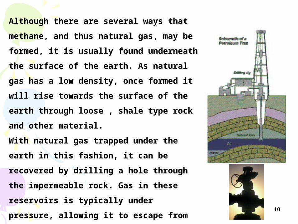
Although there are several ways that methane,
and thus natural gas, may be formed, it is
usually found underneath the surface of the
earth. As natural gas has a low density, once
formed it will rise towards the surface of the
earth through loose , shale type rock and other
material.
With natural gas trapped under the earth in this
fashion, it can be recovered by drilling a hole
through the impermeable rock. Gas in these
reservoirs is typically under pressure, allowing it
to escape from the reservoir on its own.

1111
Typical Composition of Natural Gas :
LNGLNG
Pentane
Methane
NitrogenCO2,H2S, Hg
Water
Ethane
Propane
Butane
C5 +
NGL’sNGL’s
LPGLPG
Impurities
Octane
HexaneHeptane

1212
Typical Composition of Natural Gas :

1313
Oxygen: Max. ( 0.1% ) by mole.
Carbon dioxide: Max. ( 3 % ) by mole.
Hydrogen sulphide: Max. ( 4 ) PPM
Sulphur: Max. (50 ) mgm / SCM
Mercury: Max. (6 ) mgm / SCM
Oxygen: Max. ( 0.1% ) by mole.
Carbon dioxide: Max. ( 3 % ) by mole.
Hydrogen sulphide: Max. ( 4 ) PPM
Sulphur: Max. (50 ) mgm / SCM
Mercury: Max. (6 ) mgm / SCM
**
H.C. dew point: ( +5 ) Deg.CGross Heating Value : Min. 980
Max. 1180 BTU/SCF.Water dew point : MaxPPM ( 1 ) or below
Deg. C at a pressure of ( 70 ) kg /cm2 gauge ( zero ).
H.C. dew point: ( +5 ) Deg.CGross Heating Value : Min. 980
Max. 1180 BTU/SCFWater dew point : Max. ( 1 ) PPM or below
( zero ) Deg. C at a pressure of ( 70 ) kg /cm2 gauge.
********
****

14
Natural Gas Properties

15
Ideal Gas Law
Where :
P : Absolute pressure
V : Volume
T : Absolute temperature
R : Universal gas constant
n : Number of moles n = m / M
m : Mass of the gas
M : Molecular weight
PV =
nRT
PV = (m/M) RT
m = MPV/RTm/V = ρ = MP/RT ρ is density of gas
m = MPV/RT
The ideal gas law can be expressed as :
m/V = ρ = MP/RT ρ is density of gasm = MPV/RT
m/V = ρ = MP/RT ρ is density of gas
16
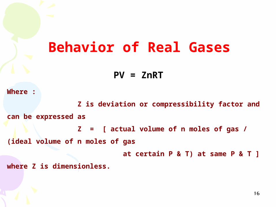
Behavior of Real Gases
Where :
Z is deviation or compressibility factor and can be expressed as
Z = [ actual volume of n moles of gas / (ideal volume of n moles of gas
at certain P & T) at same P & T ]
where Z is dimensionless.
PV = ZnRT

17
Properties of Gaseous Mixtures
Composition of natural gas may be expressed as either mole fraction, volume fraction or weight fraction.
Mole Fraction yi = ni/∑ni
where: yi : Mole fraction of component i ni : Number of moles of component i
∑ni : Total number of moles of all components in the mixtures
Volume fraction vi = vi/∑vi
Weight Fraction wi =Wi/∑Wi

18
Determination of Z Factor
From the next chart after determination of Pr and Tr we can determine Z factor
Pr
Tr
Z
Determination of Z Factor
Pr = P / PcPr = P / Pc
Where :
Pc= ∑Pci*YiTc= ∑Tci*Yi
Tr = T / Tc

19
The natural gas phase behavior is a plot of pressure vs temperature thatdetermines whether the natural gas stream at a given pressure and temperature consists of a single gas phase or two phases: gas and liquid.
The phase behavior for natural gas with a given composition is typically displayed on a phase diagram, an example of which is shown in Figure 1-1.
The left-hand side of the curve is the bubble point line and divides the single phase liquid region from the two-phase gas–liquid region.
The right-hand side of the curve is the dew point line and divides the two-phase gas–liquid region and the single-phase gas region.
Natural Gas Phase Behavior

20

21
Retrograde region
liqui
dGasx yz
At point X:
Xi=xy/zy
Yi=xz/zy
22
Definitions
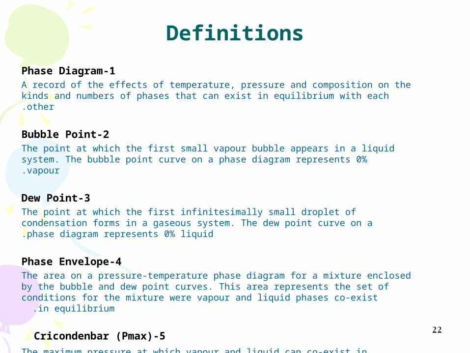
1-Phase DiagramA record of the effects of temperature, pressure and composition on the kinds and numbers of phases that can exist in equilibrium with each other.
2-Bubble PointThe point at which the first small vapour bubble appears in a liquid system. The bubble point curve on a phase diagram represents 0% vapour.
3-Dew PointThe point at which the first infinitesimally small droplet of condensation forms in a gaseous system. The dew point curve on a phase diagram represents 0% liquid.
4-Phase EnvelopeThe area on a pressure-temperature phase diagram for a mixture enclosed by the bubble and dew point curves. This area represents the set of conditions for the
mixture were vapour and liquid phases co-exist in equilibrium .
5-Cricondenbar (Pmax) The maximum pressure at which vapour and liquid can co-exist in equilibrium.

23
Definitions6-Cricondentherm (Tmax) The maximum temperature at which vapour and liquid can co-exist in equilibrium.
7-Critical PressureThe vapour pressure at critical temp.
8-Critical TemperatureThe temp. above which all the mixture cannot be liquid
9-Quality LinesLines through the two-phase region showing a constant percentage of liquid and vapour.
10-RetrogradeThe name given to phase behaviour above the critical temperature and pressure
were vapour and liquid phases coexist and the amount of vaporisation or condensation changes with pressure and temperature in the opposite direction to normal behaviour. (e.g:condensation of liquids occur by lowering pressure or increasing temperature)

24
Definitions 11-Equation of State (e.g : ideal gas law)An equation which describes the relationship between pressure, temperature and molar volume of any homogenous fluid at equilibrium
12- Critical PointThe point on the phase diagram where The bubble point and dew point lines intersect , where the distinction between gas and liquid properties disappears.
The natural gas phase behavior is a function of the composition of thegas mixture and is strongly influenced by the concentration of the heavier hydrocarbons, especially C+ . The presence of heavier hydrocarbons will increase the phase envelope and failure to include them in a phase calculation will under predict the phase envelope.As shown by the next exmple:

25

26

2727
36.1 %36.1 %
36.2 %36.2 %
3.1 %3.1 %4.9 %4.9 %
4.6 %4.6 %
7.2 %7.2 %
7.9 %
0
500
1000
1500
2000
2500
N-America S-America Europe Africa Mid-East Sov-Countries
Asia/Austr.
( TSCF )

2828
Methane:Fertilizer /Methanol/Olefin / Fertilizer /Methanol/Olefin / GTL FeedstockGTL Feedstock
Ethane :Petrochemical Petrochemical Feedstock.Feedstock.
Propane:Petrochemical Feedstock Petrochemical Feedstock or Fuel.or Fuel.
I-Butane:Refinery Feedstock / Refinery Feedstock / Fuel.Fuel.
N-Butane:Gasoline Blending / Gasoline Blending / Fuel / Petrochemical Fuel / Petrochemical Feedstock.Feedstock.
Natural Gasoline (IC5+)Condensate
Refinery Feedstock or Refinery Feedstock or Petrochemical Petrochemical Feedstock.Feedstock.
NATURAL GAS
NATURAL GAS

2929
SeparationSeparation between the Oil &Gas between the Oil &Gas
Sweetening Sweetening remove the Acid Gasesremove the Acid Gases
Dehydration Dehydration remove the Water vapourremove the Water vapour
H.C Dew Point & Heating ValueH.C Dew Point & Heating Value
Extraction (Extraction (ProcessingProcessing)) Main TargetMain Target
-Extract main component into -Extract main component into separate products which areseparate products which are
MethaneMethane
EthaneEthane
Propone Propone
LPGLPG
Natural GasolineNatural Gasoline
ConditioningConditioning
Main TargetMain Target

3030

31
Training Videos
I- Natural Gas Processing Principles
30


33
Gas ConditioningGas Conditioning
• Field Separation.• Gas Sweetening.• Gas Dehydration.

3434
Export
HP Gas
LC LC
LC
Pump
CoolingDehydration/
Desalter
Water
Heating/Cooling
Water
HP Separator
Heating/Cooling
LP Gas
LP Separator
• Large Vessels are used to separate the gas, oil, water and sand using their different densities.
• Sufficient time has to be given to allow the water droplets to settle from the oil and vice versa.
• Multiple stages are used to liberate gas and remove water.
• The number of stages is assessed balancing cost, energy efficiency, effect on the reservoir and safety.
• The separation process may require heating to help destabilise oil-water emulsions.
• Chemicals are utilised to assist droplet coalescence, break foams and prevent corrosion.
• To prevent remixing and effective separation the separator is fitted with a range of devices.

3535
Separator InternalsSeparator Internals• Internals design is often key to
efficient separator operation.
– Inlet device to reduce liquid momentum (centrifugal/impingement)
– Distributor plate– Coalesce pack to
provide surface area for small droplets to coalesce to larger ones, enhancing liquid/liquid separation
– Vane packs or demisters to collect oil droplets from the gas
– Vortex breakers to prevent gas underflow
– Sand jets to remove sand from the separator
– Foam packs

3636
Cyclone Inlet Device
Foam Reducing Pack Assembly
Inlet Diffuser & Cascade TrayBaffle Plate Set
Separator InternalsSeparator Internals
Cyclone Inlet Device with
Perforated Baffle Plate

3737
Separators TypesSeparators Types
• Horizontal Separators– Large liquid handling
capacity– Sufficient time for settle out
of liquid droplets from the gas
• Vertical Separators (scrubbers)– High gas volumes– Small footprint area
• Separator features :– Primary separation section to
separate the bulk of the liquid from the gas
– Sufficient capacity to handle liquid surges
– Sufficient liquid residence time to allow small droplets to settle out
– Some inlet device to reduce turbulence and velocity in the main separation section
– A mist extractor to capture entrained droplets
– Back pressure and liquid level controls
– Relief and blowdown– Sand washing

38
Training Videos
II- Natural Gas Separators Principles
30

3939Day#2

4040
•Sweetening process is to remove acid gases from natural gases.
•This can be done either by adsorption or absorption processes.
•The most famous adsorption process is solid desiccant beds which can perform Sweetening and dehydration for natural gas at the same time with higher efficiency.
•The most famous absorption process is amine.

4141
AMINE PROCESS

4242
CHEMICAL ABSORPTIONCHEMICAL ABSORPTION
HO-C - C-
H
H
H
H

4343

4444
Typical

45

46
FIG. 21-5Physical Properties of Gas Treating Chemicals
“weak bases”
PropertyMono-
EthanolamineDi-
EthanolamineTri-
Ethanolamine
FormulaHOC2H4NH2)HOC2H4)2NH)HOC2H4)3N
Molecular Wt61.08105.14148.19
Boiling point @ 760 mm Hg, °C
170.5269360) decompose)
Density @ 20°C, kg/m3.
101810951124

47
Check solution concentration: – Too low : Check make up water addition.Check amine flow rate: – Too low : Open by pass valve.Check amine regeneration: – Increase firing rate.Check reflux rate and temperature: – Probably too low : Increase firing rate.Check stripping column pressure: – It may be too low Check for foaming : – Carry over into outlet separator and / or pressure fluctuations across
absorber.
•A brief review of the more frequent problems and corrective procedures follow :
1- Gas is Not “ Sweet “/Dehydrated

48
• Check reboiler temperature ,pressure and the reflux rate.
• Check for leaks in lean/rich amine heat exchanger.
• Check the re-claimer for primary amine. • Check for foaming in stripper : - pressure fluctuations.
2- Amine solution not regenerated
49
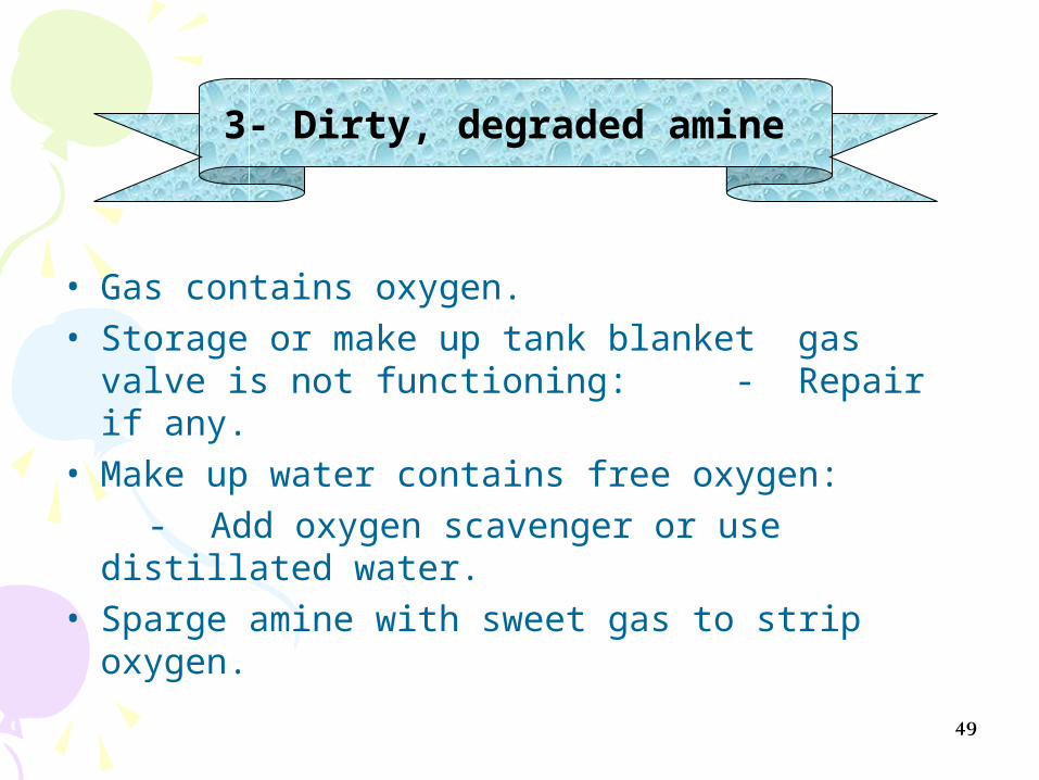
• Gas contains oxygen. • Storage or make up tank blanket gas valve is
not functioning: - Repair if any.• Make up water contains free oxygen: - Add oxygen scavenger or use distillated
water.• Sparge amine with sweet gas to strip oxygen.
3- Dirty, degraded amine
50
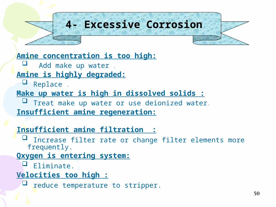
Amine concentration is too high: Add make up water .
Amine is highly degraded: Replace .
Make up water is high in dissolved solids : Treat make up water or use deionized water.
Insufficient amine regeneration:
Insufficient amine filtration : Increase filter rate or change filter elements more frequently.
Qxygen is entering system: Eliminate.
Velocities too high : reduce temperature to stripper.
4- Excessive Corrosion

51
• Foaming is a very unpredictable phenomenon. It can be caused by any or a combination of the following conditions:
Dirty amine (solids) – check filter elements. Degraded amine. Liquid hydrocarbon in gas or amine.
5- Foaming of amine solution

52
• It will be caused by lower inlet amine temperature.
• So the Inlet amine temperature must be at least 10-15 oF above the inlet gas temperature to eliminate H.C condensation .
6- Hydrocarbon condensation

53
• Well treating chemicals. • Surfactants. • Corrosion inhibitors.• Very fine particles. e.g. iron sulfide, in sour gas. • Inadequate cleaning of amine plant before
start-up.
7- Wrong or off-spec – chemicals

54
• Make up water contains iron, sulfides, chlorides, etc…
(Use deionized or de-mineralized water)
9- Incoming gas is not adequately scrubbed and contains salt water

55
• (This is really not a foaming problem but behaves so; usually with older plants).
• Note : Always add antifoaming downstream of the
carbon filter. The following antifoaming are recommended Dilute with 50% isopropyl alcohol use in
concentrations of 5 to 50 PPMW .
10- Tray down comers are plugged, causing amine to stack up in the trays

56
Training Videos
II- Gas Sweetening “Amine Uint”
18
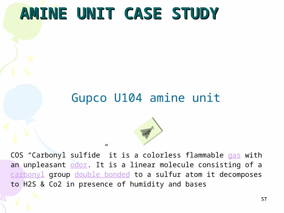
AMINE UNIT CASE STUDYAMINE UNIT CASE STUDY
57
Page 7
Gupco U104 amine unit
COS “Carbonyl sulfide” it is a colorless flammable gas with an unpleasant odor. It is a linear molecule consisting of a carbonyl group double bonded to a sulfur atom it decomposes to H2S & Co2 in presence of humidity and bases

5858
•Dehydration process is to remove water vapor from natural gases.•This can be done either by adsorption or absorption processes.• )gas 2 solid) )gas 2 liquid)
• The most famous adsorption process is solid desiccant beds which can perform Sweetening & Dehydration for natural gas at the same time with higher efficiency according to its material affinity and pour size .
• The most famous absorption process is Glycol unit.
Water in NG : Most free associated water removed by simple extraction method at
or near wellhead Water vapor in NG solution need more complex treatment Process of dehydration of NG – absorption or adsorption Pipeline specs: 7.0 lb H2O/MMSCF { max. =1 ppmv}
Day#3

59
Water Removal
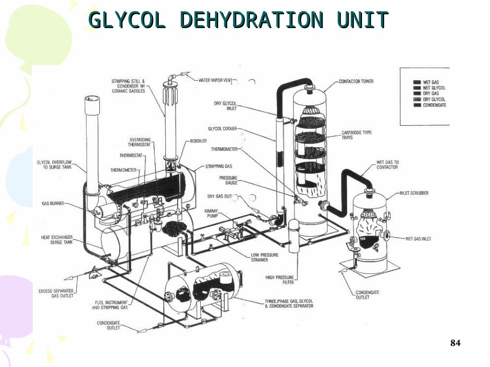
Absorption “Glycol Dehydration”:
Glycol solution (high affinity to water) – diethylene glycol (DEG) or triethylene Glycol (TEG)
TEG/DEG contact wet gas stream (called contactor) absorb water glycol soln. sink to bottom removed
Glycol recovery – vaporize glycol using special boiler New tech: addition of flash tank separator condensers
before boiler to condense methane (90 – 99% recovery)

60
Solid-Desiccant Dehydration : “Adsorption”
Adsorption process consists of 2 or more adsorption tower filled with solid desiccant.
At least 1 working, 1 regenerating Desiccants: activated alumina or granular silica gel Wet NG pass through towers from top to bottom H2O
retains on particle surface dry NG exits saturated desiccant heated with heater to vaporize water
Best suite for large volumes gas under very high P

6161

6262
HYDRATES IN NATURAL GAS SYSTEMS
• A hydrate is a physical combination of water and other small molecules to produce a solid which has an “ice-like” appearance but possesses a different structure than ice. , it cause flow interrupting.
• There are three recognized crystalline structures I,II,H
• Their formation in gas and/or NGL systems can plug pipelines, equipment, and instruments, restricting or for such hydrates. In both, water molecules build the lattice and hydrocarbons, nitrogen, CO2 and H2S occupy the cavities.

63
• HYDRATES IN NATURAL GAS SYSTEMS
• Smaller molecules (CH4, C2H6, CO2, H2S) stabilize a body-centered cubic called Structure I.
• Larger molecules (C3H8, i-C4H10, n - C4H10) form a diamond-lattice called Structure II.
• Normal paraffin molecules larger than n-C4H10 do not form Structure I and II hydrates as they are too large to stabilize the lattice.
However, some iso paraffins and cyclo –alkanes larger than pentane are known to form Structure H hydrates.

6464

6565
Hydrocarbons )C1,C2,C3,iC4+nC4) and / or H2S, N2, CO2
+Metastable H20
@)P, T)
------------------------------------------=
HYDRATES
Metastable water is liquid water which, at equilibrium, will exist as a hydrate

6666
The conditions which affect hydrate formation are:
1- Primary Considerations
• Gas or liquid must be at or below its water dew point or saturation condition. To allow water droplet condensation• Temperature.
• Pressure.
•Composition.
2- Secondary Considerations
• Mixing.
• Kinetics
• Physical site for crystal formation such as a pipe elbow, orifice, thermowell, or line scale.
• Salinity.

6767Th
P
hydrate formation line , function of composition
FIG. 20-4 Water Content of Hydrocarbon Gas

6868
Hydrate Inhibition
•The formation of hydrates can be prevented by dehydrating the gas or liquid to eliminate the formation of a condensed water )liquid or solid) phase.• In some cases, however, dehydration may not be practical or economically feasible.• In these cases, chemical inhibition can be an effective method of preventing hydrate formation.
• Chemical inhibition utilizes injection of thermodynamic inhibitors or low dosage hydrate inhibitors (LDHIs).
•Thermodynamic inhibitors are the traditional inhibitors )i.e., one of the glycols or methanol), which lower the temperature of hydrate diminish formation “Th”
•LDHIs are either kinetic hydrate inhibitors (KHIs) or anti - agglomerants (AAs).• They do not lower the temperature of hydrate formation, but do its effect.


70
Natural Gas Dehydration
by: Liquid & Solid Desiccants

71

72

73

74
75

76

77

78
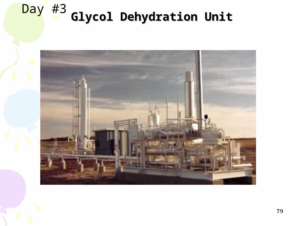
79
Glycol Dehydration UnitGlycol Dehydration UnitDay #3

80

81
Ethylene GlycolDi-ethylene Glycol
Tri-ethylene Glycol
Tetraethylene Glycol
FormulaC2H6O2C4H10O3C6H14O4C6H18O5
Molecular weight62.1106.1150.2194.2
Boiling point at 760 mm Hg, °F387.1472.6545.9597.2
Boiling point at 760 mm Hg, °C197.3244.8285.5314
Vapor pressure at 77°F (25°C) mm Hg0.120.0020.00040.00005
Vapor pressure at 140°F (60°C) mm Hg1.50.080.025< 0.01
Density (g/cc) at 77°F (25°C)1.1101.1131.1191.120
Density (g/cc) at 140°F (60°C)1.0851.0881.0921.092
Density (Kg/m3 ) at 77°F (25°C)1110111311191120
Freezing point, °C-13-8-7-5.5
Pour point, °C--54-58-41
Viscosity in centipoise at 77°F (25°C)16.528.237.344.6
Viscosity in centipoise at 140°F (60°C)4.686.998.7710.2
Surface tension at 77°F (25°C), dynes/cm47444545
Specific heat at 77°F (25°C), kJ/(kg.K)2.432.302.222.18
Flash point, °C (PMCC)116124177204
Fire point, °C (C.O.C.)118143166191
Initial decomposition temperature °C 165164207238
GLYCOLS PHYSICAL PROPERTIES
HO—)CH2)2—OH

82
Training Videos
III- Gas Dehydration “Glycol Unit”
15min
10 min.

8383
8484
GLYCOL DEHYDRATION UNITGLYCOL DEHYDRATION UNIT

85

86
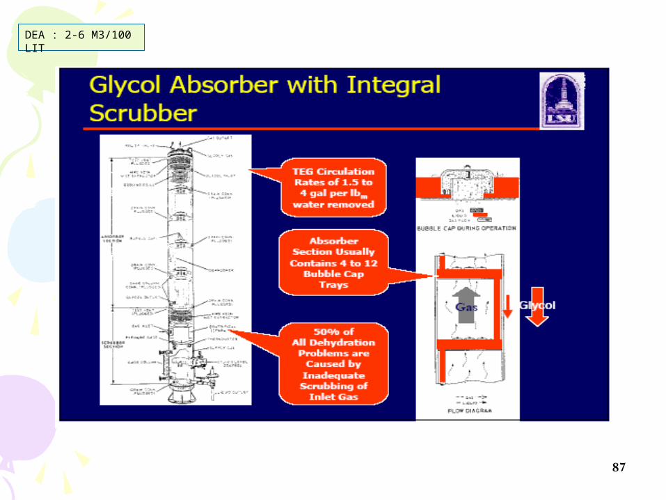
87
DEA : 2-6 M3/100 LIT

88

89

90
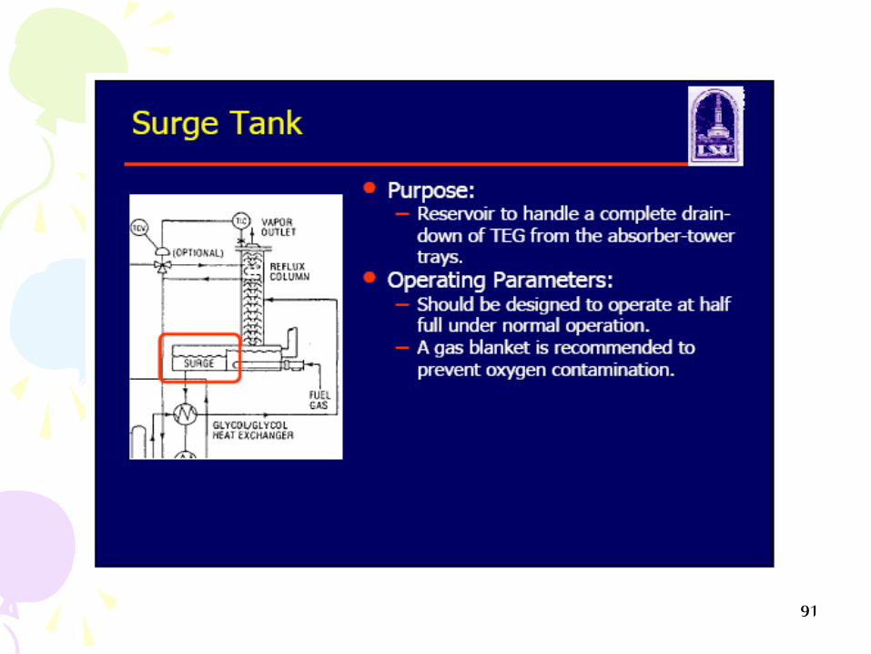
91

92
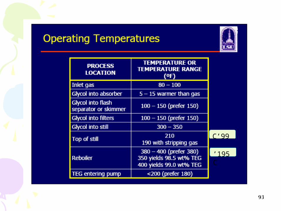
93
99’C
195 ’C

94

95

96

97
Training Videos
IV- Gas Dehydration “Principles of Glycol Unit”
15min

98
Solid Adsorpant Dehydration Solid Adsorpant Dehydration UnitUnit

9999

100100

101101
Molecular Sieves Adsorber / Internal Molecular Sieves Adsorber / Internal ArrangementArrangement

102102
GAS DEHYDRATION / Molecular sievesGAS DEHYDRATION / Molecular sieves

103103
GAS DEHYDRATION / Molecular sievesGAS DEHYDRATION / Molecular sieves

104104
GAS DEHYDRATION / Molecular sievesGAS DEHYDRATION / Molecular sieves

105105
GAS DEHYDRATION / GAS DEHYDRATION / Molecular sievesMolecular sieves

106106
GAS DEHYDRATION / Molecular sievesGAS DEHYDRATION / Molecular sieves

107107
GAS DEHYDRATION / Molecular sievesGAS DEHYDRATION / Molecular sieves

108108
GAS DEHYDRATION / Molecular sievesGAS DEHYDRATION / Molecular sieves

109
4-E34-E3
AmineAmineUnitUnit
4-V
154-
V15
4-V
434-
V43
4-H1D4-H1D
4-V
143
4-V
143
P. Eng. / A.ZP. Eng. / A.Z
GUPCO U-104 G/PGUPCO U-104 G/PDryers SchemeDryers Scheme
PH-IPH-I
PH-IIPH-II
Pg.9 Of 10Pg.9 Of 10
4-D
1A4-
D1A
4-D
1B4-
D1B
4-D
1C4-
D1C
4-F174-F17
4-F1174-F117
4-C101A/B4-C101A/B
4-C1A/B4-C1A/B
BDV-4001BDV-4001
4-C3A/B4-C3A/B
4-C103A/B4-C103A/B
ESD-1908ESD-1908
ESD-1907ESD-1907
Tie-inTie-in
Tie-inTie-in
4-D
101C
4-D
101C
4-D
101B
4-D
101B
4-D
101A
4-D
101A
4-C5A/B4-C5A/B
FV-4001FV-4001
FV-4002FV-4002F
V-4
003
FV
-400
3
FV
-400
6F
V-4
006
FV-4007FV-4007
2FV
-401
12F
V-4
011
FV
-400
5F
V-4
005
FV-4004FV-4004
2FV
-401
22F
V-4
012
2FV-40132FV-4013
2FV-40142FV-4014
2FV-40152FV-4015
2FV
-401
62F
V-4
016
2FV
-401
72F
V-4
017
2FV
-401
82F
V-4
018
2FV-40192FV-4019
2FV
-402
02F
V-4
020
4-F2174-F217
MDVMDV40014001
RDVRDV40074007
MDVMDV40034003
RDVRDV40094009
MDVMDV40054005
RDVRDV40114011
MDVMDV40024002
RDVRDV40084008
MDVMDV40044004
RDVRDV40104010
MDVMDV40064006
RDVRDV40124012
2MDV2MDV40014001
2RDV2RDV40074007
2MDV2MDV40034003
2RDV2RDV40094009
2MDV2MDV40054005
2RDV2RDV40114011
2MDV2MDV40024002
2RDV2RDV40084008
2MDV2MDV40044004
2RDV2RDV40104010
2MDV2MDV40064006
2RDV2RDV40124012

110
P. Eng. / A.ZP. Eng. / A.Z
Molecular Sieve ChargeMolecular Sieve Charge( 80,200 lb )( 80,200 lb )
Upper ScreenUpper Screen(( 20 Piece ) 20 Piece )
1” Ceramic Ball ( 52 CF )1” Ceramic Ball ( 52 CF )
1/8” Ceramic Ball ( 26 CF )1/8” Ceramic Ball ( 26 CF )
1/4” Ceramic Ball ( 26 CF )1/4” Ceramic Ball ( 26 CF )
4-D1A/B/C Dimensions4-D1A/B/C Dimensions
3”3”
3”3”
6”6”
Pg.10 Of 10Pg.10 Of 10
Lower ScreenLower Screen
Dimensions:Dimensions: 144” I.D144” I.D 20’ S/S20’ S/S

111
Table 1Table 1
Process StepProcess Step112233445566
44--D1AD1ADDDDDDHHCCDD
44--D1BD1BDDHHCCDDDDDD
44--D1CD1CCCDDDDDDDDHH
44--D101AD101ADDDDDDDDHHCC
44--D101BD101BDDDDHHCCDDDD
44--D101CD101CHHCCDDDDDDDDFV-4003, 2FV-4015, 2FV4018, FV-4003, 2FV-4015, 2FV4018,
2FV-40202FV-4020OpenOpenCloseCloseOpenOpenCloseCloseOpenOpenCloseClose
FV-4004, 2FV-4016, 2FV4017, FV-4004, 2FV-4016, 2FV4017, 2FV-40192FV-4019CloseCloseOpenOpenCloseCloseOpenOpenCloseCloseOpenOpen
Molecular Sieve Operation ChartMolecular Sieve Operation Chart

113113
DAY# 4

114
1. By lean oil absorption
2. By Refrigeration & LTS.
3. By Cryogenic Process
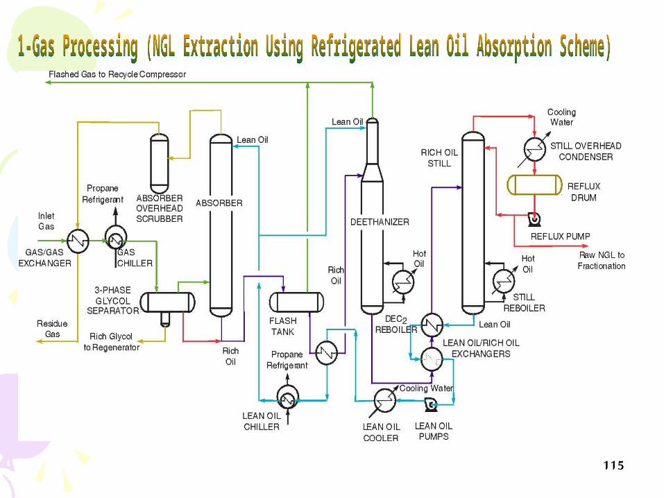
115115

116116
Sales . GasSales . GasSales . GasSales . Gas
FeedFeed
WaterWater
InletSeparator
Cond.Cond.
CompressorCompressor
Wet . GasWet . Gas
Dry . GasDry . Gas
Dehydration
ExchangerExchanger
LTSLTS
F.GF.G
To. StabilizerTo. Stabilizer
StabilzerStabilzer
FlareFlare
CoolerCooler

117117
Cryogenics : Is the study of the production of very low temperature materials )below −43°C) and the behavior of materials at those temperatures.
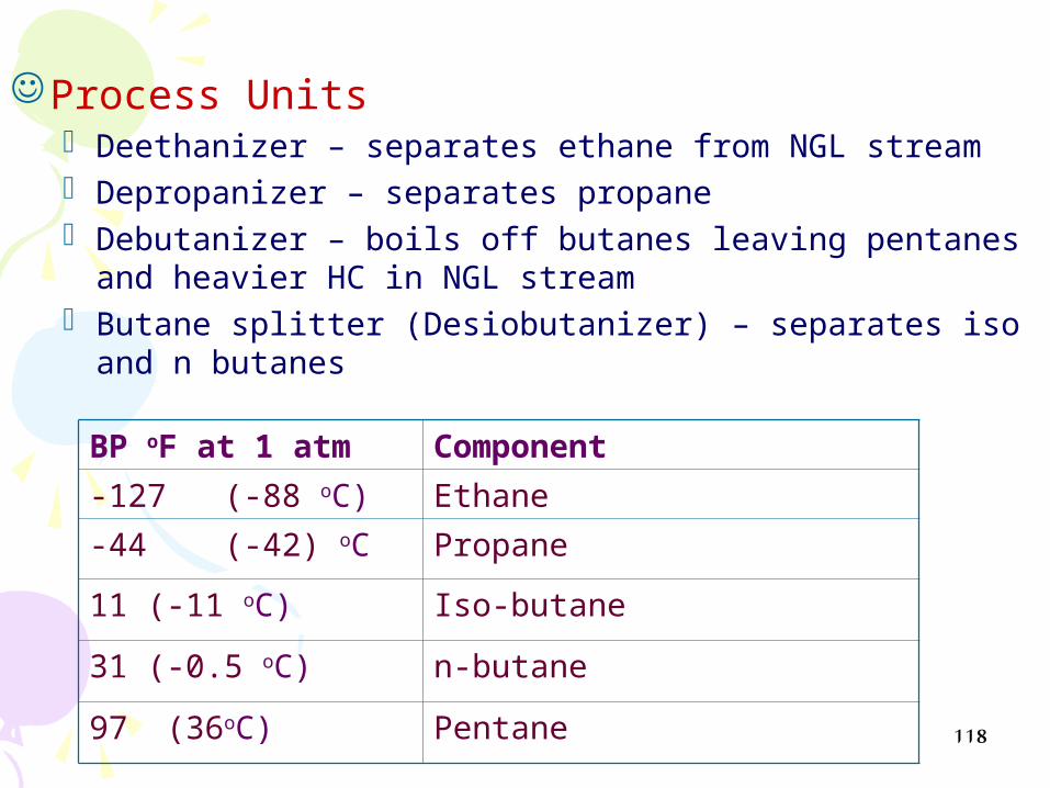
118
Process Units Deethanizer – separates ethane from NGL stream Depropanizer – separates propane Debutanizer – boils off butanes leaving pentanes and
heavier HC in NGL stream Butane splitter (Desiobutanizer) – separates iso and n
butanes
ComponentBP oF at 1 atm
Ethane-127 (-88 oC)
Propane-44 (-42) oC
Iso-butane11 (-11 oC)
n-butane31 (-0.5 oC)
Pentane 97 (36oC)

119119
Turbo Expanders• The use of turbo expanders in gas processing plants began in the early sixties.
• By 1970, most new gas processing plants for ethane or propane recovery were being designed to incorporate the particular advantages characteristic of an expander Producing usable work.
• The trend in the gas processing industry continues toward increased use of the turbo expander.
• Selection of a turbo expander process cycle is indicated when one or more of the following conditions exist:
“Free” pressure drop in the gas stream.
Lean gas.
High ethane recovery requirements )i.e., over 30% ethane recovery).
Compact plant layout requirement.
High utility costs.
Flexibility of operation )i.e:easily adapted to wide variation in pressure and products).

120120
Turbo expanders

121121
• This figure represents the pressure- temperature diagram for this expander process.
• The solid curve represents the plant inlet gas & the dashed one represent expander inlet gas )less in heavy H.C)
• At a fixed pressure and, if the temperature of the gas is to the right of this dew point line, the gas is 100 percent vapor.
• If the gas is cooled, liquid starts to condense when the temperature reaches the dew point line.
• As cooling continues, more liquid is condensed until the bubble point line is reached — the solid line on the left. At this point, all of the gas is liquid. Additional cooling results in colder liquid
Turbo expanders

122122
• A turbo expander recovers useful work from the expansion of a gas stream. • The process operates Isentropically in the ideal case and produces something less than the theoretical work in the real case. • In the process of producing work, the expander lowers the bulk stream temperature which can result in partial liquefaction of the bulk stream.
Turbo expanders

123123
De-MethaniserDe-PropaniserDe-MethaniserDe-Propaniser
To De-EthaniserDe-Butans
To De-EthaniserDe-Butans
To Sales GasCompressorTo Sales GasCompressor
Q-1Q-1
77
11
DehydrationPkg
DehydrationPkg
Feed Gas
Feed Gas
33 44
L t s L t s
Recomp
Recomp
Expander
Expander
Jt ValveJt Valve

124
Mixed Refrigerant Processes”"
Mixed Refrigerant Processes are used through LNG/NGL plants to
avail sub-cooling for natural gas where a single mixed refrigerant is used
)composed of nitrogen, methane,ethane, propane, butane and pentane).
The refrigerant is designed so that the refrigerant boiling curve nearly
matches the cooling curve of the gas being liquefied. The closeness of
the match of these two curves is a direct measure of the efficiency of the
process.

125
The low pressure refrigerant is compressed and condensed
against air or water in a closed system. The refrigerant is not totally
condensed before being sent to the cold box. The high pressure
vapor and liquid refrigerant streams are combined and condensed
in the main exchanger.
The condensed stream is flashed across a J-T valve and this low
pressure refrigerant provides the refrigeration for both the feed gas
and the high pressure refrigerant.
see fig 16-31 GPSA sec.16 in which,
“Cold box exchangers”
The cold box is a series of aluminum plate fin exchangers which provide
very close temperature approaches between the respective process streams.

126
Training Videos
IIV- Cryogenic Principles
15min

127
Examples for LPG,NGL and Examples for LPG,NGL and LNG Gas PlantsLNG Gas Plants

128128
Sales GasSales Gas
LPGLPG
COND.COND.
LPGLPG
COND.COND.
4-W1054-W105
4-W4A4-W4A
4-W4B4-W4B
4-W4C4-W4C
4-W104A4-W104A
4-W104B4-W104B
4-T
10
24
-T1
02
4-T
10
14
-T1
01
4-T
24
-T2
4-T
14
-T1
4-C3A4-C3A
4-C3B4-C3B
Chilling Area PH-IChilling Area PH-I
Chilling Area PH-IIChilling Area PH-II
Drying Area PH-IDrying Area PH-I
Drying Area PH-IIDrying Area PH-II4-C103A4-C103A
4-C103B4-C103B
4-D
1A
4-D
1A
4-D
1B
4-D
1B
4-D
1C
4-D
1C
4-D
10
1A
4-D
10
1A
4-D
10
1B
4-D
10
1B
4-D
10
1C
4-D
10
1C
4-W101B4-W101B
4-W101A4-W101A
4-W1A4-W1A
4-W1B4-W1B
Compression Area
-Compress gas press from 6-47 kg/cm .
- pre-separation for heavy H.C
Fractionation Area
- Produce LPG & Condensate
Expansion & Chilling Area
Separate Heavy H.C by cooling down to -60 ‘c
Boosting & Sales Gas Comp.
Send sales gas to GASCO net ) 64-100) kg/cm2
Utilities- Inst. Air System- Heating Oil System- Refrigeration Package- Cooling Water System- Power House- Fuel Gas System- Multi-Nozzle Flare System- Nitrogen Unit- Loading Area-Storage Area-LPG Berth # 4

129129
M
1.85 Bar120.8 C
M
30 –E -02
M
10-E-04
70 Bar30 C
1100 MMSCFD Inlet
SeparatorFilter
Dehydration Package
Mercury Removal
66 Bar40 C
28.3 Bar-50.9 C
28.5 Bar-69.5 C
-33 C
-58 C
Plat Fin
Separator
64.7 Bar-24 C
64.7 Bar-35 C
28.2 Bar-36 C
Plat Fin
25.6 Bar-43 C
CompressorTurbo
Expander
26.6 Bar-68 C
31 Bar50 C
-74.4 C
-69.5 C
Abs
orbe
r
26.6 Bar-74.5 C
26.3 Bar-76 C 25.6 Bar
-43 C
27.3 Bar-31.7 C
Demethanizer Condenser
27.3 Bar-74.4 C
-33 C
-36 C
20 Bar78.2 C
Dem
etha
nizi
er
20 Bar-78.2 C
Dep
ropa
nize
r
30-E-01
LPG Rundown
Cools 13.5 Bar50 C
LPG Local Market
1215 T/D
Deb
utan
izer
10.2 Bar62 C
10.2 Bar50 C
DNG Rundoum CoolsCondensate ( Local Market )
( 348 T/D )
Depropanizer Condenser
18 Bar50.7 C
C3 Expert
( 925 T/D )
N.G ( 1043 MMSCFD )
Sales Gas ( MMSCFD )
1043
Propane T/D925
LPG T/D1215
Condensate T/D348
Packed TowerBubble cap( 30 Tray )
Packed Tower

130

Dust Filter F-451
Dehydration Dust FilterF- 416/417
Dehydration Gas ScrubberV-410
Mercury Removal Bed V-450
Dehydration inlet Filter \ Coalescer
F-412Dehydration Adsorbers
V-413/414/415
C-121/122
Warm Gas/Gas Exchanger E-221
Deethanizer Side ReboilerE-224
Deethanizer V-521
Cold Separator V-421
Cold Gas Reflux ExchangerE-222
P-621/622/623
Deethanizer Bottom ReboilerE-225
Feed P-695/696
Depropanizer ReboilerE-241
Depropanizer Reflux CondenserA-341
Depropanizer Reflux DrumV-441
DepropanizerT-541
Propane To Storage
Butane to Storage
Feed U-104
Exp/Comp Discharge CoolerA-321
Deethanizer Reflux Acc.V-422
JT
PCV-410
Residue Gas To Pipeline
Regeneration Gas ScrubberV-418
Regeneration Gas HeaterE-211
Regeneration Gas CoolerA-311
Booster P-693/694
Depropanizer Reflux PumpsP-641/642
Regeneration Gas CompressorsC-111/112

132
15min
EXAMPLES FOR NGL GAS PLANTS
DOVE ENERGY-YEMEN PLANT

133133
NGL ExtractionNGL ExtractionTypical Product
Recoveries ( % ):Plant Type ->Product
Turbo-Expander
Joule Thompson
Lean OilRefrigeration
EthaneC2
60 – 96%45 – 60%25 – 45%1 – 5%
PropaneC3
90 – 98%85 – 95%80 – 95%20 – 40%
Iso-ButaneIC4
96 – 100%96 – 100%93 – 99%40 – 60%
N.ButaneNC4
97 – 100%97 – 100%94 – 99%40 – 60%
•NGL Recovery

134
Distillation or Fractionation Towers
and Tray Troubleshooting

135
Fractionation Towers• There are two main types of Fractionation Towers according to its
inside configuration :
• 1- Trays Towers .• 2- Packed Towers.
• Here below we will concentrate on Trays one as for its widely usage all over the world .
136
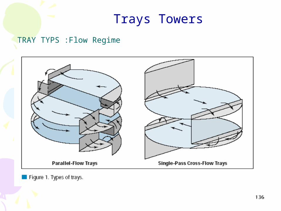
TRAY TYPS :Flow Regime
Trays Towers
137
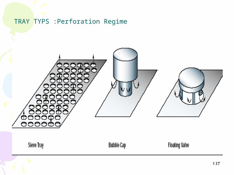
TRAY TYPS :Perforation Regime

138
TRAY TYPS :Perforation Regime

139

140

141

142
Tray Towers Problem

143
1
Tray Towers Problem

144
2
Tray Towers Problem

145
3
Tray Towers Problem
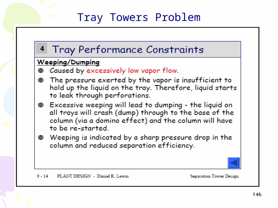
146
4
Tray Towers Problem
147
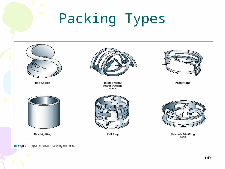
Packing Types

148

149
BOOSTER STATION UTILITIES

Pig receiver
U-102 SLUG CATCHER
FM-Ashrafi 20’’FM-Hilal 20’’
8 ’’ 8’’
4’’
Fuel To Unit
GAS COMP. 2-C1A
GAS COMP. 2-C1B
GAS COMP. 2-C1C
GAS COMP. 2-C1D
Glycol Unit.
New Glycol
Unit
PCV-308 ESDV FT
FT
TO U-104
To Flare
12 ) ’’suco pipe line(
PI 19-26 Kg/cm2.gTI 50 C
PI 4.7 Kg/cm2.gTI 34 C
FT
PV-321
20’’
16’’
Closed
Process Div
check valves internals were already removed


152
BOOSTER STATION UTILITIES
* Utilities :
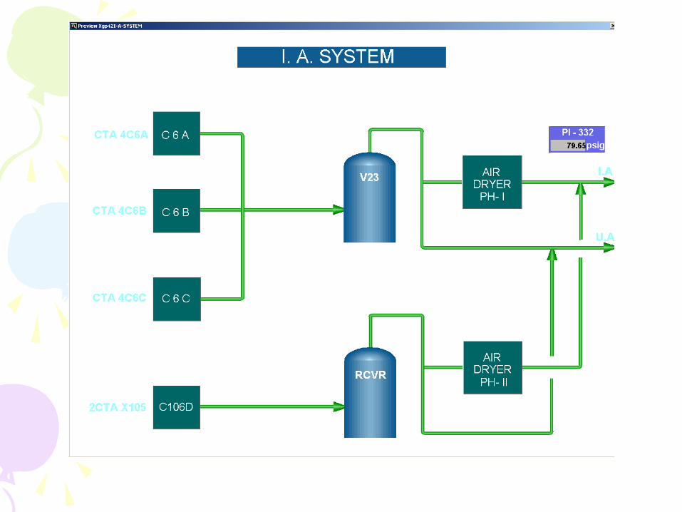
-Gas compressor-Heat Exchanger- Inst. Air System- Refrigeration Package- Cooling Water System- Power House- Fuel Gas System- Flare System- Nitrogen Unit- Storage Area

Natural GasNatural Gas CompressionCompression

Purposes of gas compression
Theory of gas compression
Main types of compressors
Centrifugal Compressor
Reciprocating Compressor

Purposes of Gas
Compression
For extra processing (liquefaction, dehydration & sweetening).
For transportation facilities.

Theory of Gas
Compression
PV = ZnRT = Z (m/M)RT
P1V1/T1 = P2V2/T2
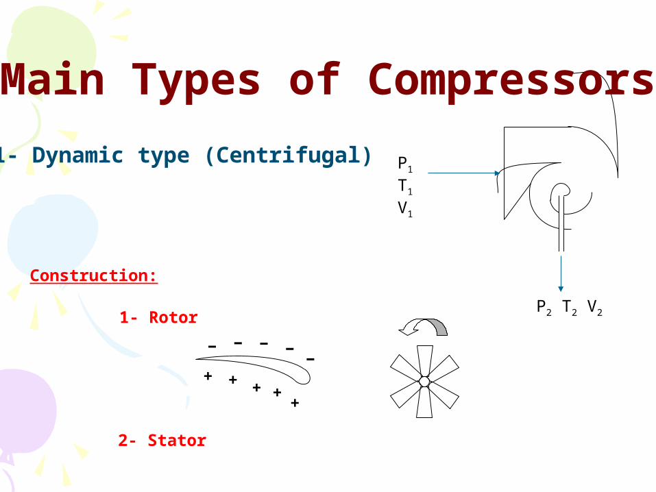
1- Dynamic type (Centrifugal) P1
T1
V1
P2 T2 V2
Main Types of Compressors
Construction:
1- Rotor
−
+ + + ++
− −−
−
2- Stator

Anti-surge Control

2-Reciprocating Compressor:
Stroke
Piston
Compression chamber
Each cylinder consists of :
Piston
Chemise
Inlet valve
Outlet valve
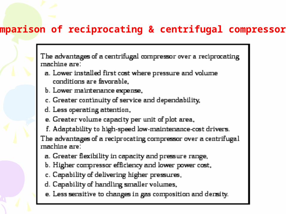
Comparison of reciprocating & centrifugal compressors


162
15min
HEAT EXCHANGERS
15min
presentationvedio

163
Air intake filter
Air Blower
Fuel Gas
Combustion chamber Plate H.E
Potable water CW in
CW out
CW out
CW in
Exhausts Comp.
After cooler
Co2&H2O Absorber
OD
OD
OD
Cond. Water tape
N2 Reservoir Design 90 psig
80fo
To plant utilities
Cooling pumps
unit PFD2 N
air
Fuel gas
Exhaust N2
Cooling water
N2 UNIT
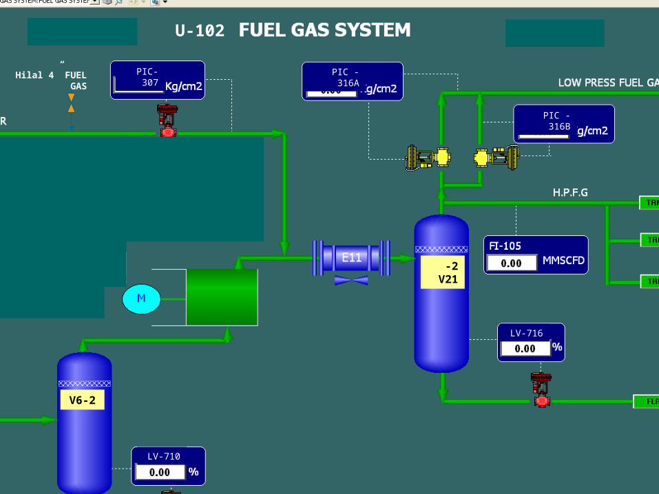
2-V21
2-V6
U-102
0
LV-716
LV-710
PIC-307 PIC -316A
PIC -316B
Hilal 4” FUEL GAS


168
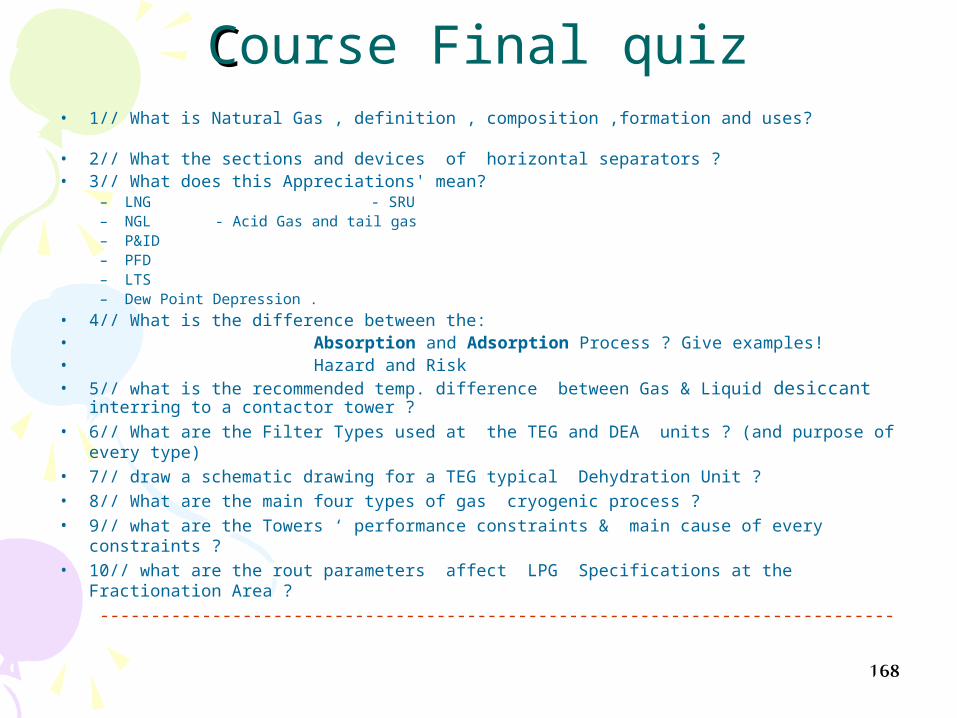
CCourse Final quiz• 1// What is Natural Gas , definition , composition ,formation and uses? • 2// What the sections and devices of horizontal separators ? • 3// What does this Appreciations' mean?
– LNG - SRU– NGL - Acid Gas and tail gas– P&ID– PFD– LTS– Dew Point Depression .
• 4// What is the difference between the:• Absorption and Adsorption Process ? Give examples! • Hazard and Risk• 5// what is the recommended temp. difference between Gas & Liquid desiccant
interring to a contactor tower ? • 6// What are the Filter Types used at the TEG and DEA units ? (and purpose of every
type) • 7// draw a schematic drawing for a TEG typical Dehydration Unit ? • 8// What are the main four types of gas cryogenic process ?• 9// what are the Towers ‘ performance constraints & main cause of every constraints ?• 10// what are the rout parameters affect LPG Specifications at the Fractionation Area
?
------------------------------------------------------------------------------

169
11// why the TEG is widely used at Glycol Dehydration?
12// what the recommended temp./pressure for TEG still reboiler ?
13// What are the booster station utilities ?
14// what is the main types of compressors ? Advantages and disadvantages?
15// what are the main types of heat exchangers ? Give exapmles of H. Exchangers at your plant ?
16// what are the two types of air coolers ?
17// what is the solid disicants used at your plants?------------------------------------------------------------------------------
170
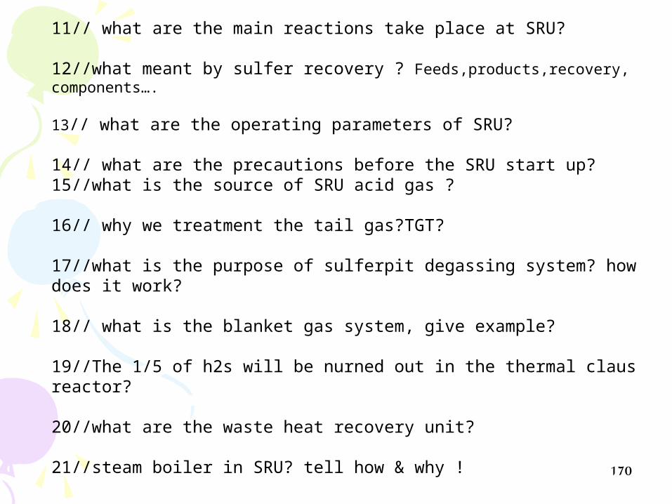
11// what are the main reactions take place at SRU?
12//what meant by sulfer recovery ? Feeds,products,recovery, components….
13// what are the operating parameters of SRU?
14// what are the precautions before the SRU start up?15//what is the source of SRU acid gas ?
16// why we treatment the tail gas?TGT?
17//what is the purpose of sulferpit degassing system? how does it work?
18// what is the blanket gas system, give example?
19//The 1/5 of h2s will be nurned out in the thermal claus reactor?
20//what are the waste heat recovery unit?
21//steam boiler in SRU? tell how & why !
------------------------------------------------------------------------------

THANKS ,,,THANKS ,,,
171
Eng. Ahmed Shoman Natural Gas Processing Engineer GUPCO "Gulf of Suez Petroleum Co."Mobile: +2-0122-743-2850 , +2-0100-800-4930e-mail: [email protected] / [email protected]


