Natural Gas Processing Solutions Using the 700XA Gas Chromatograph Application Note Oil & Gas Optimizing the efficiency and profitability of a natural gas processing plant requires responding to the changing composition of the inlet gas and adjusting the extraction of the various processes efficiently to account for market conditions. The natural gas processing applications for the 700XA gas chromatograph are designed to as pre-engineered solutions for the common applications in a field- mounted analyzer to provide real-time feedback to the control system and the operators to enable tight control of product specifications and maximize the economic return of the facility. Application Overview Natural gas processing involves removing acidic gases such as H 2 S and CO 2 and water from the raw inlet gas, extracting the condensates to produce natural gas (commonly referred to as “residue” or “sales gas”) and fractionating the condensate into various liquid products. The level of fractionation depends on the design of the plant and may only remove enough ethane for the condensate to be stable at ambient conditions (“stabilized condensate”, “NGL product”, or “Y-Grade”) or may fractionate to produce individual component products. Inlet Gas and Acid Gas Removal The composition of the inlet from the separator can vary considerably and depends on which wells are flowing, the effect of ambient conditions on the primary and inlet separator(s), and the operating state of the gathering network. Knowing the inlet gas composition will provide the basis for advanced process control models and also allow for the calculation of mass-balance and recovery rates across the process. A significant issue for gas processing plants is the risk of two-phase flow into the plant. Inlet gas flow measurement devices are designed for single-phase vapor flow only, and will generate large errors when measuring two- phase flow that will result in incorrect mass-balance and recovery calculations, and limit the implementation of advanced feed- forward control models. Additionally, if Amine systems are used to remove acidic gases, liquid hydrocarbons entering the amine contactor will cause foaming that will result in decreased throughput and off-specification products. A Typical 700XA Gas Chromatograph Configured for a Natural Gas Processing Application For this specific application, refer to the Avoiding Amine Foaming Issues Utilizing a Gas Chromatograph application note for additional information. A 700XA C9+ with the Hydrocarbon Dew Point (HCDP) calculation features gas chromatograph can help mitigate Amine foaming by determining the HCDP of the inlet gas. As the inlet gas becomes richer, the HCDP will increase, and when the HCDP is equal to the flowing gas temperature liquid hydrocarbons will begin to form. By using the 700XA C9+ HCDP gas chromatograph to calculate the HCDP at the process pressure, an alarm can be generated before the HCDP reaches the process temperature and before liquids form (Figure 1).
Transcript
Natural Gas Processing Solutions Using the700XA Gas Chromatograph
Application Note Oil & Gas
Optimizing the efficiency and profitability of a natural gas processing plant requires responding to the changing composition of the inlet gas and adjusting the extraction of the various processes efficiently to account for market conditions. The natural gas processing applications for the 700XA gas chromatograph are designed to as pre-engineered solutions for the common applications in a field-mounted analyzer to provide real-time feedback to the control system and the operators to enable tight control of product specifications and maximize the economic return of the facility.
Application OverviewNatural gas processing involves removing acidic gases such as H2S and CO2 and water from the raw inlet gas, extracting the condensates to produce natural gas (commonly referred to as “residue” or “sales gas”) and fractionating the condensate into various liquid products.
The level of fractionation depends on the design of the plant and may only remove enough ethane for the condensate to be stable at ambient conditions (“stabilized condensate”, “NGL product”, or “Y-Grade”) or may fractionate to produce individual component products.
Inlet Gas and Acid Gas RemovalThe composition of the inlet from the separator can vary considerably and depends on which wells are flowing, the effect of ambient conditions on the primary and inlet separator(s), and the operating state of the gathering network. Knowing the inlet gas composition will provide the basis for advanced process control models and also allow for the calculation of mass-balance and recovery rates across the process. A significant issue for gas processing plants is the risk of two-phase flow into the plant. Inlet gas flow measurement devices are designed for single-phase vapor flow only, and will generate large errors when measuring two-phase flow that will result in incorrect mass-balance and recovery calculations, and limit the implementation of advanced feed-forward control models.
Additionally, if Amine systems are used to remove acidic gases, liquid hydrocarbons entering the amine contactor will cause foaming that will result in decreased throughput and off-specification products.
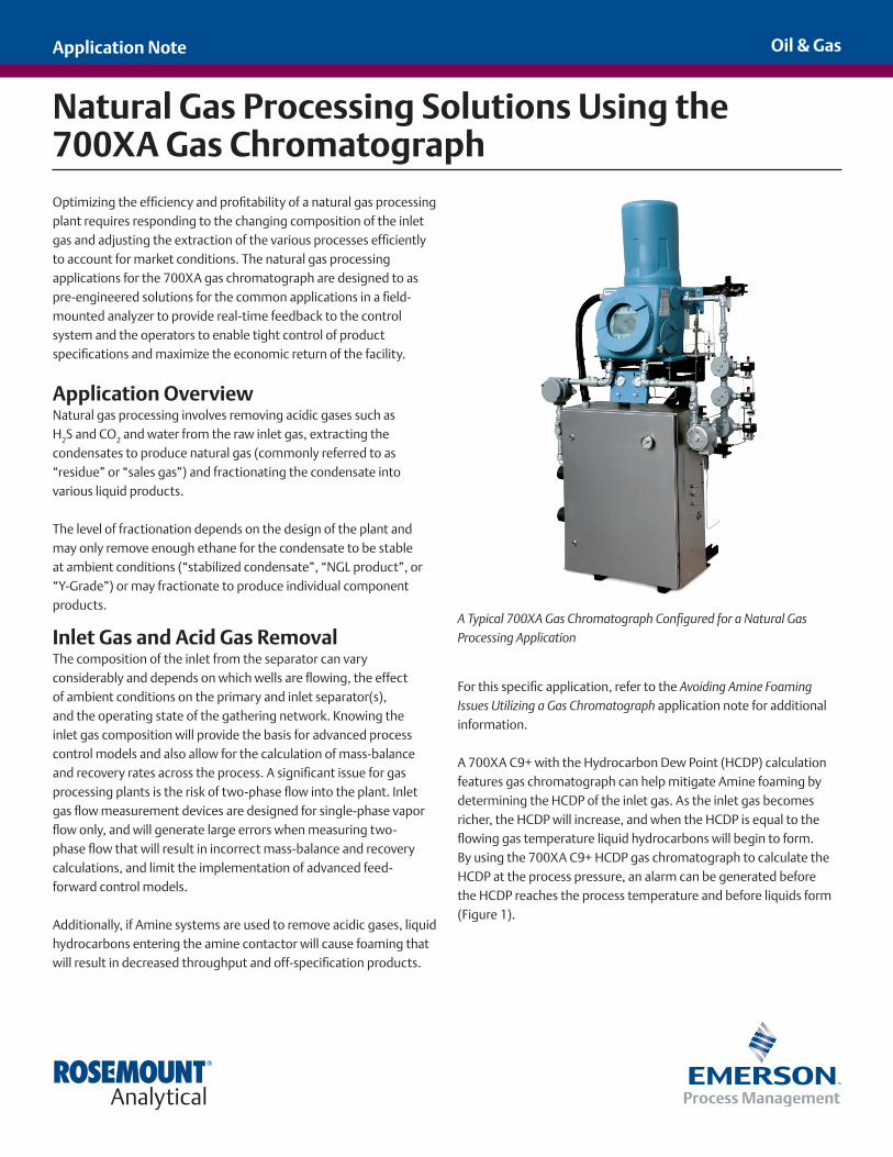
A Typical 700XA Gas Chromatograph Configured for a Natural Gas Processing Application
For this specific application, refer to the Avoiding Amine Foaming Issues Utilizing a Gas Chromatograph application note for additional information.
A 700XA C9+ with the Hydrocarbon Dew Point (HCDP) calculation features gas chromatograph can help mitigate Amine foaming by determining the HCDP of the inlet gas. As the inlet gas becomes richer, the HCDP will increase, and when the HCDP is equal to the flowing gas temperature liquid hydrocarbons will begin to form. By using the 700XA C9+ HCDP gas chromatograph to calculate the HCDP at the process pressure, an alarm can be generated before the HCDP reaches the process temperature and before liquids form (Figure 1).
Oil & Gas
Page 2
This provides an early warning of two-phase flow that operators and control systems can use to make control adjustments (such as slow down the flow through the primary separators to increase retention time and remove more condensate) and lower the risk of amine foaming and increase the accuracy of mass-balance and advanced control algorithms.
Two-phase flowcondition
Trigger to take actionto avoid HC liquids
entering thecontactor
Process Temperature
Tem
pera
ture
2-Phase Early Warning Alarm
HCDP @ Process Pressure
Figure 1 – Calculating the Hydrocarbon Dew Point of the Inlet Gas to Provide an Early Warning of Liquid Hydrocarbon Formation.
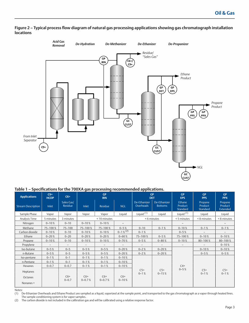
De-MethanizerThe De-Methanizer is the first stage of fractionation that separates the natural gas (“sales gas”, or “residue”) from the condensates (NGL). For small plants, this is the only fractionation that occurs and a single gas chromatograph that measures the three streams (inlet, residue gas, and NGL) may be appropriate. In these cases, the GPIRN (Inlet-Residue-NGL) standard application may be appropriate (refer to the Inlet-Residue-NGL Solutions for Natural Gas Processing Applications application note for more details). On larger plants there is sufficient justification for dedicated analyzers to provide a faster feedback of composition to provide tighter process control.
The variation of ethane in the residue gas is constrained by the sales gas tariff limits and can be accurately measured using the standard C6+ and C9+ applications used throughout the natural gas transmission segments. However, the de-methanizer bottom composition can vary considerably from one plant to another and between “rejection” and “recovery” modes, so a customized application tuned to the expected composition is the most appropriate solution when a dedicated GC is required.
Ethane RecoveryMost natural gas processing plants are designed for two modes of operation: ethane recovery or ethane rejection. The mode of operation is selected depending on the economics of the ethane and natural gas products markets.
In ethane recovery mode, the goal is to remove as much ethane from the feed as possible to be sold as ethane product. The residue stream will have very little ethane, and the de-methanizer bottoms will have relatively high levels of ethane.
When the natural gas prices are high enough to make the ethane more valuable as a part of the sales gas, or when there is low market demand for ethane, the process will be operated in ethane rejection mode, where the residue stream mode, the residue stream will have high ethane levels controlled to the gas quality limits specified in the sales gas tariffs and de-methanizer bottoms will have relatively low ethane levels.
In both modes of operation, the De-Ethanizer must still recover most of the ethane that is left in the De-Ethanizer inlet, as any ethane that is remaining in the de-ethanizer bottoms will appear in the propane product or exported NGL as a contaminant.
The De-Ethanizer Tower application (GP-DET) is designed to analyze the inlet, ethane product, and de-ethanizer bottoms in a single GC to provide accurate online feedback to the operators and the control system. The Inlet stream analysis is configured to measure the wide variations in ethane concentration found in a plant that can switch between recovery and rejection modes. The ethane overhead is configured to measure the ethane and contaminants at the concentrations typically found in ethane purity specifications, and the de-ethanizer bottoms stream is configured for a wide range of NGL compositions.
To ensure the ethane product meets the contractual specifications, the Ethane Product or GP-EPS application (shown on Figure 2), is configured for a dedicated fast analysis of the ethane and the commonly specified contaminants. A typical ethane specification is > 95 % ethane, < 1 % Ethylene, and < 3.5 % propane or heavier hydrocarbons. As ethylene levels in raw natural gas are rarely high enough to result in off specification concentrations in natural gas processing, the GP-EPS application measures the methane, ethane, propane and butanes and heavier hydrocarbons as well as carbon dioxide.
Notes:(1) De-Ethanizer Overheads and Ethane Product are sampled as a liquid, vaporized at the sample point, and transported to the gas chromatograph as a vapor through heated lines. The sample conditioning system is for vapor samples.(2) The carbon dioxide is not included in the calibration gas and will be calibrated using a relative response factor.
Liquid samples are initially conditioned through a liquid particulate filter with fast bypass loop and armored rotameter mounted externally to the main SCS enclosure (Figure 4). A very low volume side stream is passed into the vaporizing regulator mounted inside the heated SCS enclosure. The vaporized sample passes through a manual ball valve that allows for the manual calibration of the liquid analysis and then is injected into the GC oven through a dedicated sample injection valve in the analytical oven.
All sample injection valves vent through dedicated atmospheric referencing valves to enable the purging samples to be routed to a safe sample vent (such as to the flare, vapor recovery system, or back into the process) while enabling the sample loop to be referenced to atmospheric pressure prior to injection into the analytical flow path to ensure accurate and repeatable measurements.
All of the vapor state sample conditioning components are mounted inside a stainless steel heated cabinet that can optionally include a viewing window for easy system checks. The sample systems can be mounted integral to the 700XA gas chromatograph, or mounted remotely.
The 700XA Recommended SolutionsThe 700XA recommended applications are designed with the heritage of remote and unattended operation that places the emphasis on reliability and ease of use over complexity. The hardware is designed to maximize reliability that results in several years between maintenance (and thus, downtime) on the analytical oven.
The entire system is factory tested in an environmental chamber that ramps the temperature from -18 °C to 55 °C (0 °F to 130 °F) over 24 hours. This final test not only ensures that your gas chromatograph leaves the factory meeting the promised specifications; it also ensures peak performance on-site whether the 700XA is installed close to the process exposed to the ambient conditions, or installed in an enclosed shelter.
Propane RecoveryMany small plants will export the NGL to a fractionation facility after the ethane removal as “stabilized NGL” that is best analyzed with a customized gas chromatograph application tailored to the specifics of the feed gas and the process. Larger plants may recover the propane and must meet propane product specifications.
A common industry specification is the GPA 2140 HD-5 propane specification of > 90 % propane, < 5 % propylene, and < 2.5 % butanes and heavier hydrocarbons. Most processors do not need to continuously analyze the propylene levels, and to ensure a fast analysis, the standard Propane Purity application (GP-PPS) measures methane, ethane, propane, i-butane, n-butane, and pentanes and heavier hydrocarbons. The extended propane purity application (GP-PPX) adds the propylene measurement for locations that do need to continuously measure the propylene concentration.
System DesignThe sample system design is critical to the performance of any analyzer system. For the vapor systems, particulate filters, liquid filters, check-valves, and bypass flow rotameters are included as standard (Figure 3). Flow switches in the bypass flow can be included as an option. To ensure there is no contamination between the sample and the calibration streams, double-block-and-bleed solenoids are used.
Oil & Gas
Page 5
700XA Specifications and DrawingsPlease consult Rosemount Analytical if your requirements are outside the specifications listed below. Improved performance, other products and material offerings may be available depending on the application.
Communications (Standard) � Ethernet: Two ports – one RJ-45 and one four-wire
with 10/100 mbps � Analog inputs: Two standard isolated inputs filtered with transient
protection, 4–20 mA (user scalable and assignable) � Analog outputs: Six isolated outputs, 4–20 mA � Digital inputs: Five inputs, user assignable, optically isolated,
rated to 30V DC @ 0.5 A � Digital outputs: Five user-assignable outputs, Form C and
electromechanically isolated, 24V DC � Serial: Three termination blocks, configurable as RS-232, RS-422 or
RS-485 and one RS-232 D-sub (9-pin) Modbus/PC Connection
Communications (Optional)Two expansion slots available for additional communications.Each slot has the capacity to add one of the following:
� Four analog inputs (isolated) card
� Four analog outputs (isolated) card
� Eight digital inputs (isolated) card
� Five digital outputs (isolated) card
� One RS-232, RS-422 or RS-485 serial connection card
� One modem card, 300-19.2k baud
Additionally, a FOUNDATION™ fieldbus module is available.
Memory Capacity: 1 GB of flash memory for data storage; 128 MB of SDRAM system memory with 2 MB static RAM (battery-backed)
ConstructionEnvironmental temperature: -20° to 60 °C (-4° to 140 °F)
Environmental temperature without safety certification: 40° to 60 °C (-40° to 140 °F)
Enclosure Protection Rating: IP66
• Dimensions (without sample system):
• Wall-mount: 711 mm H x 445 mm W x 498 mm D
(28'' H x 17.5'' W x 19.6'' D)
• Pipe-mount: 711 mm H x 445 mm W x 671 mm D
(28'' H x 17.5'' W x 26.4'' D)
• Floor-mount: 1532 mm H x 445 mm W x 612 mm D
(60.3'' H x 17.5'' W x 24.1'' D)
Corrosion Protection:
•GCEnclosureMaterial: Copper free aluminum coated with industrial grade powder coat suitable for high humidity and salt- laden environments.
•ProcessWettedMaterials: Stainless steel. Where the function of an item excludes the use of stainless steel (e.g. glass rotameter tubes), materials that are resistant to corrosion are used.
•Electronics:All electronic circuit boards are tropicalized with a clear conformal coating.
Mounting: Floor-standing (standard), wall- or pipe-mount (optional)
Approximate Weight (without sample system): 50 kg (110 lbs.)
Area Safety Certification Options:*
� CSA: – USA and Canada
• Class I, Division 1, Groups B, C, and D � ATEX / IECEx
– Ex II 2G – Ex d IIC Gb T6
(Ta = -20 °C to 60 °C)
*Stated T-ratings can vary based on applications.
Performance CapabilitiesOven: Airless, maximum 150 °C (302 °F)Valves: Six-port and ten-port diaphragm chromatograph valves. Other types of valves, such as liquid injection or rotary valves, may be used depending on the application
Carrier Gas: Application-dependent. Typically zero-grade helium, nitrogen, or hydrogen
Sample & Calibration Gas Input Pressure Range:
0.2068–2.0684 bar: 1.0342 bar (recommended) or 15 psig
Carrier Gas Input Pressure Range (recommended): 6.2052–6.8947 bar (90–100 psig)
ElectronicsPower:
� Standard: 24V DC (21–30V DC)
� Optional: 90–264V AC, 47–63 Hz
Typical Power Consumption at 22 °C (72 °F): � Startup: 105 Watts DC (125 Watts AC) � Steady State: 35 Watts DC (40 Watts AC) � Steady State with LOI: 50.5 Watts DC (58 Watts AC)
Touch Key Local Operator Interface (Optional) The 700XA local operator interface (LOI) allows for maintenance and
operation of a 700XA without a laptop or PC. The LOI is a state-of-the-art
high resolution color display that is touch key infrared activated and supports
Gating Options: Fixed-time, slope sensing gating of peaks
Streams: Up to 20 externally controlled streams or up to 8 internal (includes calibration stream)
Chromatograms stored/archived internally: Stores over 80 days of analysis report data and up to 2500 individual chromatograms.
Oil & Gas
Page 6
Recommended InstallationThe drawings below represent the minimum recommended installation guidelines for the 700XA Gas Chromatograph. Please consult Rosemount Analytical for detailed installation recommendations for your application.
Figure 5 – GPIRN OD Local
Figure 6 – GPIRN OD Remote
Oil & Gas
Page 7
Option SelectionUse the matrix below to choose the options for your application and build up the model string to order.
700XA -GPSCS -
1
--
2
--
3
--
4
--
5
--
6
--
7
--
8
--
9
700XA 700XA Process Gas Chromatograph
Level 1 Hazardous Area Approval
A ATEX/IEC-Ex
C CSA rated
Level 2 Mounting
F Floor-mount
P Pipe-mount
W Wall-mountLevel 3 Power
AC Universal 85 to 240V AC
DC 24V DCLevel 4 Front Panel
EN Extended switch panel - 18 streams switches and FID ignite button (ignitor not used inless option XX-YY are chosen on level 12)
SK Local Operator Interface (LCD)
SN Standard switch panel - eight stream switches - not available when an FID option is selected on Level 12
Level 5 Additional* I/O and Serial/Modem Communications - Slot A
5A Additional I/O Port - Four Additional Channels of Analog Inputs (Isolated)
5D Additional I/O Port - Eight Additional Channels of Digital Inputs (Isolated)
5M Modem5N None5P Additional I/O Port - Four Additional Channels of Analog Outputs
(Isolated)5R Additional Serial Port - (1) RS422 or 485 (Factory/Field
configurable) 5S Additional Serial Port - (1) RS2325T Additional I/O Port - Five Additional Channels of Digital Outputs
(Isolated)
Level 6 Additional* I/O and Serial/Modem Communications - Slot B6A Additional I/O Port - Four Additional Channels of Analog Inputs
(Isolated)6D Additional I/O Port - Eight Additional Channels of Digital Inputs
(Isolated)6M Modem6N None6P Additional I/O Port - Four Additional Channels of Analog Outputs
(Isolated)6R Additional Serial Port - (1) RS422 or 485 (Factory/Field
configurable) 6S Additional Serial Port - (1) RS2326T Additional I/O Port - Five Additional Channels of Digital Outputs
(Isolated)
Level 7 FOUNDATION™ Fieldbus Interface
1F Interface Module
Level 8 Sample System Mounting LocationL Local Sample System - Sample System mounted under GC, with
tubing and signaling connections by RAIR Remote Sample Handling System - Includes an external junction
box for SHS signal wiring, attached to the 700XA. Signal Wiring and tubing connections are others.
Level 9 Gas Processing Application
GPIRN Gas Processing - Inlet Residue NGL (three streams)
GPDET DeEthanizer Tower Overheads and Bottoms (two streams)GPEPS Ethane Purity
GPPPS Propane Purity
GPPPX Propane Purity Extended (with Propylene)
GPSCS Sample Conditioning System for 700XA- Gas Processing Applications
Level 2 Hazardous AreaA Local Sample SystemC CSA rated components - Class I, Division 1, Groups B, C, D
Level 3 MountingLS1 Local Sample System - Sample System mounted under GC, with
tubing and signaling connections by RAIRS1 Remote Sample Handling Sysem - Includes external junction
box, with signal wiring and tubing connection by others.
Level 4 PowerA1 110V ACA2 220V AC
Level 5 WindowPL Plexiglass - Lexan
Level 6 Vapor Flow Switches
V1 Single Vapor Flow SwitchV2 Two Vapor Flow SwitchesV3 Three Vapor Flow SwitchesV4 Four Vapor Flow Switches
Level 7 Vapor Sample EntryH1 Single Vapor Heat Trace BootH2 Two Vapor Heat Trace BootsH3 Three Vapor Heat BootsH4 Four Vapor Heat Trace BootsB ⅛ Bulkhead Fittings
Level 8 Liquid Flow Switches
L1 Single Liquid Flow SwitchL2 Two Liquid Flow SwitchL3 Three Liquid Flow SwitchesL4 Four Liquid Flow Switches
Optional Accessories
Vapor Sample ProbeProvide line size, process connection details, process pressure and temperature.
Vapor Sample Probe/Regulator
Provide line size, process connection details, process pressure and temperature.
Vaporizing Regulator For remote mount at the sample pointHeating Sample Probe For vapor samples. To be mounted at the sample point.Liquid Sample Probe Provide line size and process connection details.Heat Traced Sample Line
The Emerson logo is a trademark and service mark of Emerson Electric Co. Rosemount Analytical is a mark of one of the Emerson Process Management family of companies. All other marks are the property of their respective owners.
The contents of this publication are presented for information purposes only, and while effort has been made to ensure their accuracy, they are not to be construed as warranties or guarantees, express or implied, regarding the products or services described herein or their use or applicability. All sales are governed by our terms and conditions, which are available on request. We reserve the right to modify or improve the designs or specifications of our products at any time without notice.
MIDDLE EAST AND AFRICAEmerson Process ManagementEmerson FZE Jebel Ali Free ZoneDubai, United Arab Emirates, P.O. Box 17033T +1 855-725-2638 (855 RAI-AND-U)T +971 4 811 8100F +971 4 886 [email protected]
AMERICASEmerson Process Management Rosemount Analytical Analytical Center of Excellence10241 West Little York, Suite 200Houston, TX 77040 USA T +1 855-725-2638 (855 RAI-AND-U)Toll Free 866 422 3683T +1 713 396 8880 (North America)T +1 713 396 8759 (Latin America)F +1 713 466 [email protected]