23
Final Report | 0 Nautical Autonomous System with Task Integration Final Report Authors: Terry Max Christy & Jeremy Borgman Advisors: Dr. Gary Dempsey & Nick Schmidt May 11, 2012
F i n a l R e p o r t | 0
Nautical Autonomous System with Task Integration
Final Report
Authors: Terry Max Christy & Jeremy Borgman
Advisors: Dr. Gary Dempsey & Nick Schmidt
May 11, 2012

F i n a l R e p o r t | 1
CONTENTS
Project Summary....................................................................................................................................................................... 2
Specifications ......................................................................................................................................................................... 2
System Overview ...................................................................................................................................................................... 3
Motor Interfacing Module ................................................................................................................................................. 4
Thruster Circuitry ............................................................................................................................................................. 4
Differential Drive Circuitry ............................................................................................................................................ 5
Bidirectional Relay Circuitry ......................................................................................................................................... 6
Remote Control ..................................................................................................................................................................... 6
Communication ..................................................................................................................................................................... 7
Beagleboard & Operating System ................................................................................................................................... 8
High level Control Scheme ................................................................................................................................................. 9
Buoy Detection ................................................................................................................................................................. 9
Channel Navigation ....................................................................................................................................................... 11
Obstacle Avoidance ....................................................................................................................................................... 13
Results ......................................................................................................................................................................................... 13
Works Consulted...................................................................................................................................................................... 14
Appendix A Buoy Detection Algorithm ............................................................................................................................. 15
Appendix B Path Constructor .............................................................................................................................................. 19
Appendix C Control Signal Generation ............................................................................................................................. 20
Appendix D: Atmega 128 Software.................................................................................................................................... 22
F i n a l R e p o r t | 2
PROJECT SUMMARY
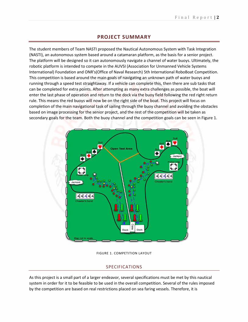
The student members of Team NASTI proposed the Nautical Autonomous System with Task Integration
(NASTI), an autonomous system based around a catamaran platform, as the basis for a senior project.
The platform will be designed so it can autonomously navigate a channel of water buoys. Ultimately, the
robotic platform is intended to compete in the AUVSI (Association for Unmanned Vehicle Systems
International) Foundation and ONR's(Office of Naval Research) 5th International RoboBoat Competition.
This competition is based around the main goals of navigating an unknown path of water buoys and
running through a speed test straightaway. If a vehicle can complete this, then there are sub tasks that
can be completed for extra points. After attempting as many extra challenges as possible, the boat will
enter the last phase of operation and return to the dock via the buoy field following the red right return
rule. This means the red buoys will now be on the right side of the boat. This project will focus on
completion of the main navigational task of sailing through the buoy channel and avoiding the obstacles
based on image processing for the senior project, and the rest of the competition will be taken as
secondary goals for the team. Both the buoy channel and the competition goals can be seen in Figure 1.
FIGURE 1. COMPETITION LAYOUT
SPECIFICATIONS
As this project is a small part of a larger endeavor, several specifications must be met by this nautical
system in order for it to be feasible to be used in the overall competition. Several of the rules imposed
by the competition are based on real restrictions placed on sea faring vessels. Therefore, it is

F i n a l R e p o r t | 3
appropriate to apply these restrictions to the NASTI as it can be foreseen that the image processing and
autonomous bay navigation could be used in real world applications. First, the boat must follow the
three R’s of bay navigation, red right return. That means that the boat must keep the red buoys to the
right of the boat and the green buoys to the left when returning to port, and vice versa when leaving.
Also, the channel navigation must be completed in a timely manner for both the purpose of meeting the
time restrictions of the competition and in a real application other sea goers don’t want to wait forever
for an autonomous system to leave and enter the port. The algorithm would also be optimized for both
crafts entering and leaving port. Finally, an obstacle avoidance algorithm must be in place for the
obvious safety reasons. An autonomous system cannot cause damage or injury or it would never make it
to production. Following these restrictions, the system implemented must maintain the red right return
rule, complete the channel navigation within five minutes, and successfully avoid the yellow obstacle
buoy. Therefore, the image processing system must be able to differentiate between three different
colored buoys. The red and green gate buoys, and the yellow obstacle buoys. These methods will be
explained later in the paper.
SYSTEM OVERVIEW
Shown below in Figure 2 is a detailed overview of the autonomous boat. This is a high level visual of the
data flow from the data acquisition to the motor control. There are seven major sub-systems each of
which will be discussed below in a bottom up order, starting with the motor interfacing module and
ending with the 32 bit control code written for the embedded system located in the B.R.A.I.N.S. module.
FIGURE 2. SYSTEM OVERVIEW
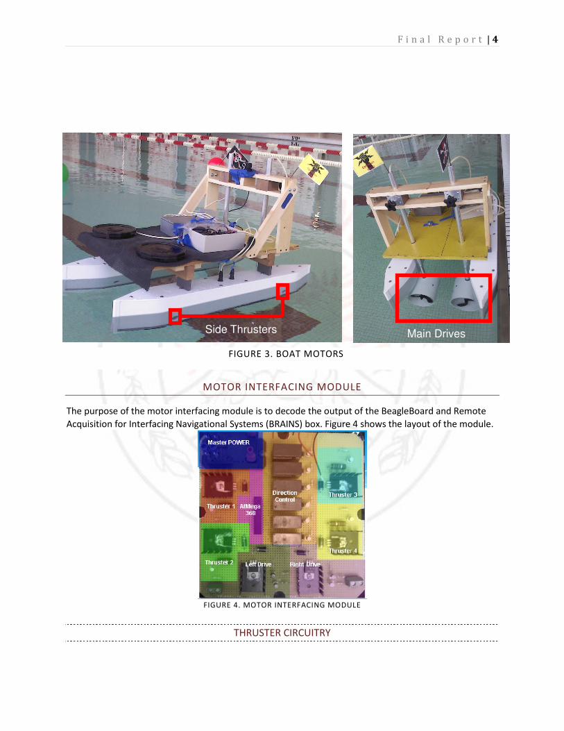
Figure 3 (next page) shows the actual side thrusters and main drive motors. The small holes in the
side will be known as side thrusters. The two larger motors in the aft will be referred to as main
drive motors.
F i n a l R e p o r t | 4
MOTOR INTERFACING MODULE
The purpose of the motor interfacing module is to decode the output of the BeagleBoard and Remote
Acquisition for Interfacing Navigational Systems (BRAINS) box. Figure 4 shows the layout of the module.
FIGURE 4. MOTOR INTERFACING MODULE
THRUSTER CIRCUITRY
Side Thrusters Main Drives
FIGURE 3. BOAT MOTORS
F i n a l R e p o r t | 5
As can be seen in Figure 2, there are four side thrusters to help pivot the boat and move it laterally. The
thrusters require twelve volts and have an estimated peak current of 3A. To accommodate these
requirements, the circuit in Figure 5 was created. The microcontroller can source a maximum of 40mA
and the motor requires 3A. Additionally the motor runs on 12 volts and the microcontroller runs on 5
volts. The hFE of Q1 was not large enough to increase the current to the needed 3A. for this reason, two
transistors were used. Diode D1 was added as a freewheeling diode to prevent the reverse voltage
generated by the motor from damaging the transistor Q2.
FIGURE 5. THRUSTER CIRCUITRY
DIFFERENTIAL DRIVE CIRCUITRY
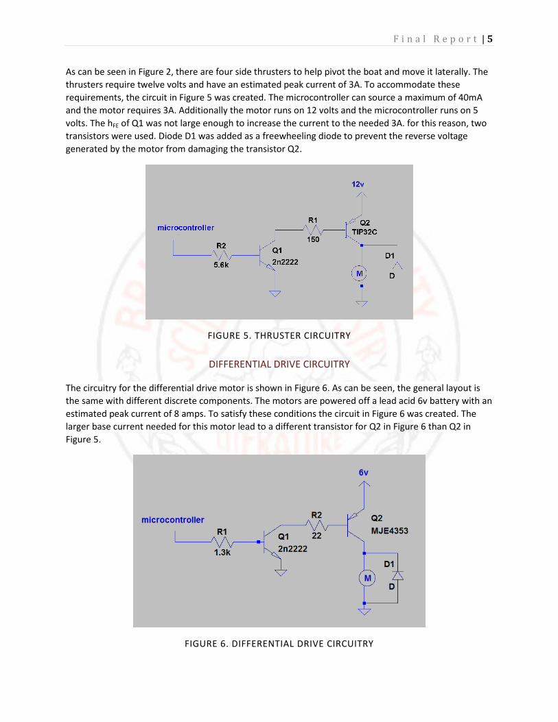
The circuitry for the differential drive motor is shown in Figure 6. As can be seen, the general layout is
the same with different discrete components. The motors are powered off a lead acid 6v battery with an
estimated peak current of 8 amps. To satisfy these conditions the circuit in Figure 6 was created. The
larger base current needed for this motor lead to a different transistor for Q2 in Figure 6 than Q2 in
Figure 5.
FIGURE 6. DIFFERENTIAL DRIVE CIRCUITRY

F i n a l R e p o r t | 6
BIDIRECTIONAL RELAY CIRCUITRY
All of the motors needed to be run in either direction which necessitated implementing bi-directionality
circuitry. The high current specifications combined with the goal for a low cost solution ruled out most
of the typical methods to achieve bi-directionality. A double pull double throw relay connected to a
switching transistor was ultimately utilized. This can be seen in Figure 7. When the coil of the relay
becomes active, the switch moves into the open position. This flips the polarity of the motor resulting in
the motor turning in a different direction.
REMOTE CONTROL
Using the Futaba T6EX R/C transmitter (shown on next page) with the Futaba R617FS receiver and the
communication protocol described above, a remote control scheme has been developed for emergency
control of the boat and for use in testing. In this control scheme, the platform is allowed 3 degrees of
freedom that can be controlled from 3 axis of the transmitter joysticks. To enter this emergency control
mode, the right shoulder switch has to be flipped in the downward position to force the master
Atmega128 in the B.R.A.I.N.S. module to send motor control bytes based on the r/c commands rather
than the BeagleBoard control signal. This is shown in Figure 8 on the next page.
Vcc
M + -
Vcc
FIGURE 7: BIDIRECTIONAL RELAY CIRCUITRY

F i n a l R e p o r t | 7
FIGURE 8. R/C TRANSMITTER
In Figure 8 the yellow arrow is pointing to the control switch. The left joystick ratchets in the vertical
directions. This axis is then used for throttle control of the main drive motors. The horizontal motion of
the left joysticks provides a strafing thrust from the pontoon mounted side thrusters. The final degree of
freedom is controlled by the right joysticks horizontal motion. This signal will rotate the boat in place
using the side mount thrusters.
COMMUNICATION
As can be seen in Figure 9 there are two microcontrollers, a BeagleBoard, the RC control receiver, and
the interfacing circuitry that all must communicate. This section will describe the communication
protocols. Figure 9 (below) shows the protocols used to facilitate the communication between the
different boards. The AtMega128 code can be found in Appendix D.
FIGURE 9. COMMUNICATION OVERVIEW

F i n a l R e p o r t | 8
The output of the RC receiver is a 0-5v 50 Hz servo control signal. The length of the pulse corresponds to
how far the RC lever is pulled. The AtMega128 records the length of the pulses and decodes them into a
signal to be sent to the Atmega368. This value is temporarily saved.
In the case of autonomous mode, the AtMega128 receives the decoded motor packet over the serial
port from the BeagleBoard. This value is also temporarily saved.
A decoded motor packet consists of nine bytes. The first three bytes are *** which indicates to the
AtMega368 that new motor instructions are incoming. The next six bytes correspond to each of the six
motors. The first seven bits of each byte represent a pulse width modulated (PWM) value from 0-99%.
The last bit corresponds to the directionality of the motor. This coding scheme allows for a minimal
amount of data to be transmitted.
When the AtMega368 receives a new motor packet it first checks to see if any motor has changed
direction. If a motor has indeed changed direction, the motor is turned off for 250ms. This is to prevent
large current spikes from damaging the motor circuitry. After a directionality check has been performed
the PWM for each motor is updated.
BEAGLEBOARD & OPERATING SYSTEM
All the image processing and path planning code is executed on a BeagleBoard-XM. This program runs
an embedded linux distribution stored on a SD card with the executions taking place on a TI ARM
Cortex–A8 processor. It shipped with a distribution called Angstrom and many software packages and
kernel modules. Many of these modules were not needed. To allow for a faster boot time and less
overhead on computations, a new image was generated using the Narcissus online image builder. Other
distributions were benchmarked, including Ubuntu 10.10 for ARM. However, a comparison of the
BogoMIPS reveals the fastest OS to be Angstrom. BogoMIPS is an estimated measurement of
instructions executed per second.
After this new image was installed, the serial port on the BeagleBoard was configured to allow for
programming without a monitor. Since the operating system image was completely minimized, no
kernel modules were installed. The only modules that were subsequently installed were a wireless,
webcam, and serial-usb driver.
As explained in the next section of this paper, our vision system is implemented using the open source
image processing library called OpenCV. This library has already been ported for an ARM processor. The
Angstrom package manager was used to install and configure the library. As a benchmark, the library
was natively compiled on the BeagleBoard but no significant improvement to the frames per second was
noticed.
The final task in readying the BeagleBoard was creating MakeFile for multi-file compiling. Since the
BeagleBoard is an embedded system it is not practical to install an IDE to facilitate managing multi file
projects. This is done through the use of MakeFiles. Essentially the make utility takes a makefile which
explains all the interdependencies, links them, compiles them into objects, and then creates an
executable.

F i n a l R e p o r t | 9
HIGH LEVEL CONTROL SCHEME
The high level control code for the autonomous system has been written in object oriented C++. Using
this method, the project is able to use classes, structures, and vectors to define the information in the
autonomous system. This partially removes the concern with the hardware limitations of the control
device so that the software can be designed at a higher level.
Ultimately, the control scheme is based around a vision system. The code reads in an image from a web
camera that is mounted to the top of the motor mount bar on the stern of the boat. The system uses
only one camera to reduce complexity and processor computation time. Therefore, the system does not
rely on stereoscopic vision, but rather uses the fact that the boat will be facing the buoy channel
entrance and the reasonable assumption that the channel is mostly straight. With these assumptions in
mind, the code can begin to process the images using a set of libraries known as OpenCV. These libraries
allow the use of high level functions to perform image processing with an optimized implementation.
The first step in this process is to determine a horizon level. This would ideally be the location where the
edge of the pond meets the ground and sky in the image. However, for the sake of simplicity and
reduced computation, it is assumed that the horizon is fixed an roughly one third of the way down the
image. With this information, the algorithm determines a region of interest (ROI) to be the bottom two
thirds of the image and performs all further processing on that part of the image. This both reduces the
computation time on the image, and reduces the false buoys that can be found by objects that are not in
the pond or pool. After this step has been performed, the algorithm can search for the red, green, and
yellow buoys.
BUOY DETECTION
After the code has determined the ROI in an image from the camera, it is stored into an OpenCV data
type called an IplImage. This image is then converted from the RGB (Red Green Blue) color space into
the HSV (Hue Saturation Value) color space. This step is performed because the autonomous system is
expected to perform under various lighting conditions. When the buoys are under different light, the
RGB values can range wildly while the HSV values change only slightly. The saturation is the most likely
to change as the buoy is a reflective surface and direct sunlight will almost completely flood a portion of
the buoy in white color.
With this knowledge, a set of constant threshold values can be set for each of the three color channels.
This is repeated for each color of buoy that the program needs to detect. Using these bounds, the areas
that contain the buoy colors can be determined using an optimized search algorithm. This process
creates a second binary image by threshholding the pixels that fall into the defined color regions and
setting them to 255, or the color white. This leaves the buoys clearly defined in the image, but the
locations and sizes still needs to be determined relative to the image.
To determine this information, another C++ library is used that is optimized to quickly search through an
image and determine ‘blobs’ of color in that image. The library is called cvblobslib. The functions
operate by assuming a blob is an area of connected color pixels given certain known second order
statistics and threshold values. CBlobResult, the function that returns the blob information, requires a
binary or grayscale input image. To put it simply, the function searches through the image and locates
areas that contain pixels that are of a value higher than the provided threshold. It then looks at the

F i n a l R e p o r t | 10
surrounding pixels and change in color level from pixel to pixel to determine the bounds of the ‘blob’ of
color. After locating all the blobs the function returns a vector of blob objects.
The blob object then contains several parameters that provide information about that blob. The most
important to the code is the min/max x and y locations of the blob. From this information the center and
radius of the buoy can be estimated in terms of pixels. The buoys are then stored into a vector, where
they are sorted from the bottom-most buoy of that color in the image to the highest. The driver for the
camera that is used returns the xy axis in reference to the top left most pixel as the origin, and the
positive y values count down as in Figure 10. A detailed explanation of this process can be found in
Appendix A.
FIGURE 10. XY PLOT DESCRIPTION
FIGURE 11. OPENCV DRAW CIRCLE CODE
F i n a l R e p o r t | 11
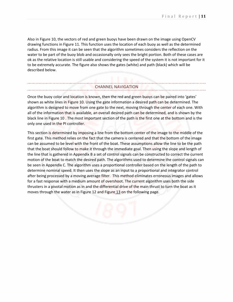
Also in Figure 10, the vectors of red and green buoys have been drawn on the image using OpenCV
drawing functions in Figure 11. This function uses the location of each buoy as well as the determined
radius. From this image it can be seen that the algorithm sometimes considers the reflection on the
water to be part of the buoy blob and occasionally only sees the bright portion. Both of these cases are
ok as the relative location is still usable and considering the speed of the system it is not important for it
to be extremely accurate. The figure also shows the gates (white) and path (black) which will be
described below.
CHANNEL NAVIGATION
Once the buoy color and location is known, then the red and green buoys can be paired into ‘gates’
shown as white lines in Figure 10. Using the gate information a desired path can be determined. The
algorithm is designed to move from one gate to the next, moving through the center of each one. With
all of the information that is available, an overall desired path can be determined, and is shown by the
black line in Figure 10 . The most important section of the path is the first one at the bottom and is the
only one used in the PI controller.
This section is determined by imposing a line from the bottom center of the image to the middle of the
first gate. This method relies on the fact that the camera is centered and that the bottom of the image
can be assumed to be level with the front of the boat. These assumptions allow the line to be the path
that the boat should follow to make it through the immediate goal. Then using the slope and length of
the line that is gathered in Appendix B a set of control signals can be constructed to correct the current
motion of the boat to match the desired path. The algorithms used to determine the control signals can
be seen in Appendix C. The algorithm uses a proportional controller based on the length of the path to
determine nominal speed. It then uses the slope as an input to a proportional and integrator control
after being processed by a moving average filter. This method eliminates erroneous images and allows
for a fast response with a medium amount of overshoot. The current algorithm uses both the side
thrusters in a pivotal motion as in and the differential drive of the main thrust to turn the boat as it
moves through the water as in Figure 12 and Figure 13 on the following page.

F i n a l R e p o r t | 12
FIGURE 12. LEFT TURN
Port
Thrust
Motor
Interface
Module
Starboard
Thrust
Port-Stern
Thrust
Port-Bow
Thrust
Starboard-
Stern Thrust
Starboard-Bow
Thrust
FIGURE 13. RIGHT TURN
Upon completion of the channel navigation, there will be a blue buoy to mark the end of the channel. At
this point another control algorithm would take over in order to locate and travel to one or more of the
challenge stations of the competition, however that is not part of the senior design so will be omitted
from this report. After attempting the tasks and returning to the buoy channel, the channel navigation

F i n a l R e p o r t | 13
algorithm can take control again with a red right return mantra to port navigation. In this scheme, the
red buoy will be on the right of the boat as it returns to port where it will need to dock.
OBSTACLE AVOIDANCE
Scattered through the buoy channel there are a few yellow buoys which are considered obstacles by the
program. The program first identifies the yellow buoys by the color as described above, then determines
a threat level based on its vertical positioning in the image. If there is a yellow buoy that is closer to the
boat then the first gate, it moves into the extremely hazardous mode in which the yellow buoy must be
avoided at all costs. To achieve this, a line from the bottom of the image to the yellow buoy is
determined and using the slope of this line as the signal to be controlled an avoidance algorithm takes
over. The control scheme can be considered an avoidance gradient where the peaks of avoidance are
the center of the image and the lower edges. This gradient can be described as two valleys on either
side of the center. It then becomes desirable to keep the yellow buoy in these valleys. The slope of the
yellow buoy line will then determine how hard the boat needs to turn. If the slope indicates that the
buoy is far enough to the side of the boat, but not so far that the boat may be veering off course, then
the boat can remain traveling in the direction it is heading. If the slope indicates that the boat is going to
hit the buoy, or that it is moving too far off course, then the control algorithm needs to correct for this
discrepancy. Once again, a proportional control is used to accomplish this task.
The main concern with this method becomes remaining on course. If the boat attempts to turn too hard
away from the obstacle it may lose sight of the yellow buoy, the next gate, or all of the buoys. If it does
lose sight of all of the buoys, a search algorithm will take control and the boat will rotate in place to
search for a new gate to head to. The program will know if it is the correct gate to head through to
advance through the channel if it follows the three R’s mantra. If the only gate that can be found is in
the wrong direction, it can at least travel to it and try to start over.
RESULTS
Through this report, the Nautical Autonomous System with Task Integration has been described in great
detail. The system overview introduces the system, giving a quick description of each sub system and
how they interact. The paper then describes the BeagleBoard and operating system set up which flows
into a description of the motor interfacing module. Then the communication protocol between the
systems is explained, followed by the remote control scheme and finally summed together with the
image processing work.
There were problems, as there should be in any engineering endeavor. Some of which have been solved,
others remain for future work. The power electronics circuits were in a confined box, and the
components are very close to each other, this resulted in shorts and component failures. These have
been mitigated by regulatory circuitry and isolation materials. Also, the boat floated but not perfectly.
The bonding material on the pontoons is damaged by the salt water in the pool and no longer holds the
pontoons together. This has also been handled by been corrected as well. Aside from all of the hardware
issues, there have been software problems as well.
F i n a l R e p o r t | 14
The main problem that arises with the image processing is the field of view of the camera. When the
boat is attempting to track the desired path generated by the image, it often overshoots from the inertia
of the boat combined with the overshoot introduced by the control system. When this happens, one of
the gate buoys may be pushed out of the field of view and the boat then does not properly generate the
desired path and the navigational scheme fails. To correct this, a future team could consider adding a
second camera and stitching the images together to form a wide view of the area in front of the boat.
Another option would be to mount the camera to a servo, or attach a lens to the front of the camera
that would widen the single camera’s field of view. This last option my result in a distorted image that
cannot reliably be used for the navigational scheme that is in place.
Also, the BeagleBoard must be programed remotely so that the code can be changed from a laptop on
the shore while the BeagleBoard remains on the boat platform. This results in a large down time in
between a test and flashing new algorithm. To mitigate this wasted time as much as possible, a set of
parameters (top speed, min speed, kp, ki, kd, etc.) could be input to the main code from a text file so
that that file could be changed on the fly for tuning purposes without having to recompile the entire
code.
Ultimately, project NASTI was able to overcome most of these barriers. Thus culminating in an
autonomous system that is able to use the image processing techniques described through this paper to
provide control signals to a functional electronic interfacing system and navigate a channel of red and
green buoys as well as identify and avoid the yellow obstacle buoys.
WORKS CONSULTED
[1] “The Four Elements" 4th International RoboBoat Competition Final Rules. Arlington, VA:
AUVSIfoundation. PDF.
[2] Bradski, Gary Rost., and Adrian Kaehler. Learning OpenCV. Beijing: O'Reilly, 2008. Print.

F i n a l R e p o r t | 15
Appendix A Buoy Detection Algorithm
/*
This function takes an image, the y coordinate of the horizon, a char representation of
the color that is to be located, a vector to put the informoation in, and a lighting as
input paramaters and will return an Iplimage. The color char is used in an if tree to
determine the threshold values that are to be used when performing the threshold function
on the HSV image. The image is converted from RGB color space to HSV color space before
processing is performed because the HSV color space is less responsive to various light
conditions.
*/
IplImage* findBuoy(IplImage* in, int horizon, char color, vector<buoy> &buoys, char lighting)
{
/* the following section uses the horizon information to create a region of interest */
IplImage* out = cvCreateImage(cvGetSize(in), in->depth, in->nChannels);
cvCopy(in, out, NULL);
int x = out->origin;
int y = 0;
int width = out->width;
int height = out->height + y;
int add = 100;
if(horizon < out ->height){y = out->origin + horizon;}
else{y = out->origin;}
//Make a recatangle with the full x length of the image and the height from the bottom of the image to the
//horizon point
CvRect water = cvRect(x,horizon,width,height);
cvSetImageROI( in, water);
/***********************************************************************************/
IplImage* hsvImg = cvCreateImage(cvGetSize(in), IPL_DEPTH_8U, 3);
IplImage* thresholded = cvCreateImage(cvGetSize(in), IPL_DEPTH_8U, 1);
IplImage* thresholded2 = cvCreateImage(cvGetSize(in), IPL_DEPTH_8U, 1);
IplImage* thresholded3 = cvCreateImage(cvGetSize(in), IPL_DEPTH_8U, 1);
/*
The HSV colorspace uses 0-360 to represent the color values(hue) in a circular chart.
In doing this, it splits the red spectrum down the middle so anything that contains
red needs to be searched for on the low and high end of the hue values. This is the reason
for the three thresholded images. thresholded and thresholded2 can be used to search multiple
location on the hsv chart and thresholded3 is the or'ed together image.
To make things even more interesting, openCV uses chars to represent the values for hue,
saturation, and value. Rather than scaling 0-360 to 0-255 they chose to cut the resolution
in half so hue is represented from 0 to 180.
*/
CvScalar hsv_min;
CvScalar hsv_max;
CvScalar hsv_min2;
CvScalar hsv_max2;
F i n a l R e p o r t | 16
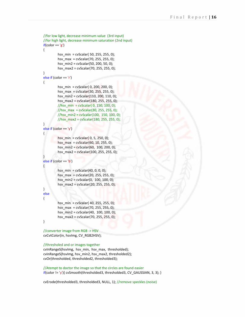
//for low light, decrease minimum value (3rd input)
//for high light, decrease minimum saturation (2nd input)
if(color == 'g')
{
hsv_min = cvScalar( 50, 255, 255, 0);
hsv_max = cvScalar(70, 255, 255, 0);
hsv_min2 = cvScalar(50, 200, 50, 0);
hsv_max2 = cvScalar(70, 255, 255, 0);
}
else if (color == 'r')
{
hsv_min = cvScalar( 0, 200, 200, 0);
hsv_max = cvScalar(30, 255, 255, 0);
hsv_min2 = cvScalar(110, 200, 110, 0);
hsv_max2 = cvScalar(180, 255, 255, 0);
//hsv_min = cvScalar( 0, 150, 100, 0);
//hsv_max = cvScalar(30, 255, 255, 0);
//hsv_min2 = cvScalar(100, 150, 100, 0);
//hsv_max2 = cvScalar(180, 255, 255, 0);
}
else if (color == 'y')
{
hsv_min = cvScalar( 0, 5, 250, 0);
hsv_max = cvScalar(60, 10, 255, 0);
hsv_min2 = cvScalar(60, 100, 200, 0);
hsv_max2 = cvScalar(100, 255, 255, 0);
}
else if (color == 'b')
{
hsv_min = cvScalar(40, 0, 0, 0);
hsv_max = cvScalar(20, 255, 255, 0);
hsv_min2 = cvScalar(0, 100, 100, 0);
hsv_max2 = cvScalar(20, 255, 255, 0);
}
else
{
hsv_min = cvScalar( 40, 255, 255, 0);
hsv_max = cvScalar(70, 255, 255, 0);
hsv_min2 = cvScalar(40, 100, 100, 0);
hsv_max2 = cvScalar(70, 255, 255, 0);
}
//converter image from RGB -> HSV
cvCvtColor(in, hsvImg, CV_RGB2HSV);
//thresholed and or images together
cvInRangeS(hsvImg, hsv_min, hsv_max, thresholded);
cvInRangeS(hsvImg, hsv_min2, hsv_max2, thresholded2);
cvOr(thresholded, thresholded2, thresholded3);
//Atempt to doctor the image so that the circles are found easier
if(color != 'y'){ cvSmooth(thresholded3, thresholded3, CV_GAUSSIAN, 3, 3); }
cvErode(thresholded3, thresholded3, NULL, 1); //remove speckles (noise)
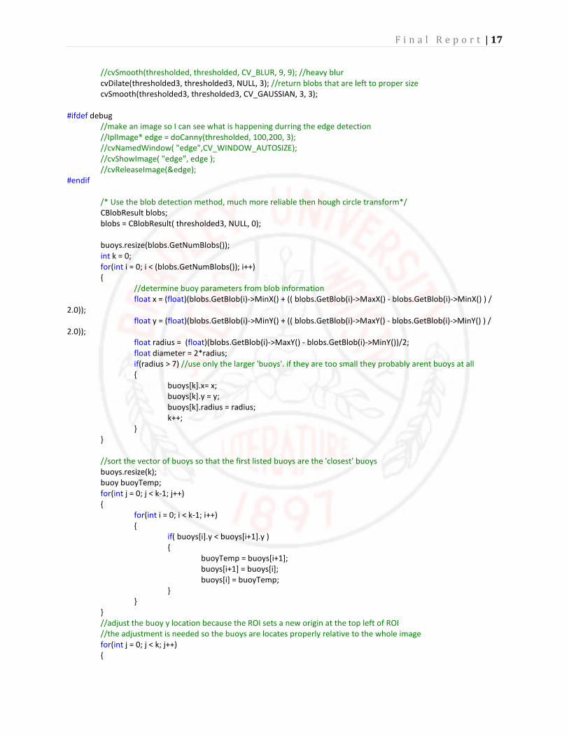
F i n a l R e p o r t | 17
//cvSmooth(thresholded, thresholded, CV_BLUR, 9, 9); //heavy blur
cvDilate(thresholded3, thresholded3, NULL, 3); //return blobs that are left to proper size
cvSmooth(thresholded3, thresholded3, CV_GAUSSIAN, 3, 3);
#ifdef debug
//make an image so I can see what is happening durring the edge detection
//IplImage* edge = doCanny(thresholded, 100,200, 3);
//cvNamedWindow( "edge",CV_WINDOW_AUTOSIZE);
//cvShowImage( "edge", edge );
//cvReleaseImage(&edge);
#endif
/* Use the blob detection method, much more reliable then hough circle transform*/
CBlobResult blobs;
blobs = CBlobResult( thresholded3, NULL, 0);
buoys.resize(blobs.GetNumBlobs());
int k = 0;
for(int i = 0; i < (blobs.GetNumBlobs()); i++)
{
//determine buoy parameters from blob information
float x = (float)(blobs.GetBlob(i)->MinX() + (( blobs.GetBlob(i)->MaxX() - blobs.GetBlob(i)->MinX() ) /
2.0));
float y = (float)(blobs.GetBlob(i)->MinY() + (( blobs.GetBlob(i)->MaxY() - blobs.GetBlob(i)->MinY() ) /
2.0));
float radius = (float)(blobs.GetBlob(i)->MaxY() - blobs.GetBlob(i)->MinY())/2;
float diameter = 2*radius;
if(radius > 7) //use only the larger 'buoys'. if they are too small they probably arent buoys at all
{
buoys[k].x= x;
buoys[k].y = y;
buoys[k].radius = radius;
k++;
}
}
//sort the vector of buoys so that the first listed buoys are the 'closest' buoys
buoys.resize(k);
buoy buoyTemp;
for(int j = 0; j < k-1; j++)
{
for(int i = 0; i < k-1; i++)
{
if( buoys[i].y < buoys[i+1].y )
{
buoyTemp = buoys[i+1];
buoys[i+1] = buoys[i];
buoys[i] = buoyTemp;
}
}
}
//adjust the buoy y location because the ROI sets a new origin at the top left of ROI
//the adjustment is needed so the buoys are locates properly relative to the whole image
for(int j = 0; j < k; j++)
{

F i n a l R e p o r t | 18
buoys[j].y = buoys[j].y + horizon;
}
#ifdef debug
cvNamedWindow( "HSV",CV_WINDOW_AUTOSIZE);
cvShowImage( "HSV", thresholded );
cvNamedWindow( "thresholded",CV_WINDOW_AUTOSIZE);
cvShowImage( "thresholded", thresholded3 );
cvNamedWindow( "thresholded2",CV_WINDOW_AUTOSIZE);
cvShowImage( "thresholded2", thresholded2 );
#endif
cvReleaseImage(&thresholded);
cvReleaseImage(&thresholded2);
cvReleaseImage(&hsvImg);
cvReleaseImage(&out);
return(thresholded3);
}

F i n a l R e p o r t | 19
APPENDIX B PATH CONSTRUCTOR
/*
Determine the desired path based on the series of gates. Origionally the control sheme used
the information gathered from the bottom middle of the image to the first gate, since then
a new control signal is used. This function doesn't serve much of a purpuse other than providing
visual information to be drawn on the debugging image.
*/
int findPath(IplImage *in, vector<gate> &gates, vector<path> &path)
{
int x, y;
if(gates.size() > 0){path.resize(gates.size());}
else {path.resize(1);}
//cout<<path.size()<<endl;
path[0].nearEnd = cvPoint( in->width/2, in->height);
if( gates.size() > 0 )
{
path[0].height = (float)in->height;
path[0].farEnd = gates[0].goal;
path[0].slope = (float)(path[0].farEnd.y - path[0].nearEnd.y)/(float)(path[0].farEnd.x -
path[0].nearEnd.x);
x = (path[0].farEnd.x - path[0].nearEnd.x);
y = (path[0].farEnd.y - path[0].nearEnd.y);
path[0].length = sqrt((float)((x*x) + (y*y)));
for(unsigned int i = 1; i < gates.size(); i++)
{
path[i].nearEnd = gates[i-1].goal;
path[i].farEnd = gates[i].goal;
path[i].slope = (float)(path[i].farEnd.y - path[i].nearEnd.y)/(float)(path[i].farEnd.x -
path[i].nearEnd.x);
x = (path[i].farEnd.x - path[i].nearEnd.x);
y = (path[i].farEnd.y - path[i].nearEnd.y);
path[i].length = (float)y; //sqrt((float)((x*x) + (y*y)));
}
}
else
{
path[0].farEnd = cvPoint(cvRound(in->width/2), 0);
path[0].slope = (float)(path[0].farEnd.y - path[0].nearEnd.y)/(float)(path[0].farEnd.x -
path[0].nearEnd.x);
x = (path[0].farEnd.x - path[0].nearEnd.x);
y = (path[0].farEnd.y - path[0].nearEnd.y);
path[0].length = sqrt((float)((x*x) + (y*y)));
}
return(0);
}

F i n a l R e p o r t | 20
APPENDIX C CONTROL SIGNAL GENERATION
/*
This function provides a low pass filter for the control signal.
This is used to smooth a transition from one gate to the next or to maintain heading
if one of the buoys is momentarily lost (not found or move out of FoV)
*/
CvPoint rollAverage(vector<CvPoint> &averageBuff, vector<path> &path)
{
float X = 0.0;
float Y = 0.0;
//rotate out the old value
for(unsigned char i = averageBuff.size()-1; i >0; i--)
{
averageBuff[i] = averageBuff[i-1];
}
//insert the new value
averageBuff[0] = cvPoint(path[0].farEnd.x, path[0].farEnd.y);
for(unsigned char i = 0; i < averageBuff.size(); i++)
{
X += averageBuff[i].x;
Y += averageBuff[i].y;
}
X /= averageBuff.size();
Y /= averageBuff.size();
return(cvPoint((int)X, (int)Y));
}
void constructControl(CvPoint *start, CvPoint *end, path *control)
{
int x, y;
control->nearEnd = *start;
control->farEnd = *end;
control->slope = (float)(control->farEnd.y - control->nearEnd.y)/(float)(control->farEnd.x - control->nearEnd.x);
x = (control->farEnd.x - control->nearEnd.x);
y = (control->farEnd.y - control->nearEnd.y);
control->length = sqrt((float)((x*x) + (y*y)));
}
void intigrator(CvPoint *sum, CvPoint *newPoint, float Ki, float width)
{
sum->x = (int)((sum->x - width/2.0) + Ki*(newPoint->x - width/2.0));
sum->x = (int)(sum->x + width/2.0);
sum->y = (int)(newPoint->y) ;//+ Ki*(newPoint->y);
}
CvPoint differentiator(CvPoint *old, CvPoint *in, float Kd, float width)
{
CvPoint out;
out.x = (int)(Kd*(in->x - old->x - width));

F i n a l R e p o r t | 21
out.x += (int)(width/2.0);
out.y = in->y;
old->x = in->x;
return(out);
}
void navigateChannel(path *control, vector<float> &motors, float height, float closingOnGateDen, float closingPWM,
float PWMoffset, float maxThrottle, float diffCoef, float leftOff, float rightOff)
{
float closingOnGate = height/closingOnGateDen;
float throttlePWM = 0;
float LturnOffset = 0;
float RturnOffset = 0;
float aheadSlope = 5.0;
char direction = 'N';
char severity = 'N';
if(control->length < closingOnGate)
{
cout<<"WE'RE GOING IN!!!!!"<<endl;
//set throttle value to an 'enter gate' speed
throttlePWM = closingPWM;
}
else
{
//don't need to turn
if(abs(control->slope) > aheadSlope)
{
cout<<"Dead ahead Cap'n"<<endl;
severity = 'N';
direction = 'F';
}
//need to turn **REMOVING THE SEVERITY, SIDE THRUST DOESNT MAKE ENOUGH DIFERENCE**
else
{
//need to turn left
if(control->slope > 0)
{
direction = 'L';
}
//need to turn right
else
{
direction = 'R';
}
//need a hard turn
if(abs(control->slope) < 1.0)
{
cout<<"Turning Hard: "<<direction<<endl;
severity = 'H';
}
//need a slight turn
else
F i n a l R e p o r t | 22
{
cout<<"Turning Slightly: "<<direction<<endl;
severity = 'H';
}
}
//set throttle value proportional to the length of the path line
throttlePWM = (control->length / height)*(float)100.0 + PWMoffset;
if(throttlePWM > maxThrottle) throttlePWM = maxThrottle;
else throttlePWM = throttlePWM;
}
if(direction == 'L')
{
LturnOffset = diffCoef*(aheadSlope - abs(control->slope));
if(LturnOffset >= throttlePWM){ LturnOffset = throttlePWM; }
else if(LturnOffset < 1.0) { LturnOffset = 0; }
RturnOffset = 0.0;
}
else if(direction == 'R')
{
RturnOffset = diffCoef*(aheadSlope - abs(control->slope));
if(RturnOffset >= throttlePWM){ RturnOffset = throttlePWM; }
else if(RturnOffset < 1.0) { RturnOffset = 0; }
RturnOffset = 0.0;
}
else
{
LturnOffset = 0;
RturnOffset = 0;
}
turn(severity, direction, motors);
//throttle(throttlePWM, motors);
mainThrust(leftOff*(throttlePWM - LturnOffset), rightOff*(throttlePWM - RturnOffset), motors);
}
APPENDIX D: ATMEGA 128 SOFTWARE


