Page 1
AD0In 11PS69-88-001
NAVAL POSTGRADUATE SOKrOOLMonterey, California
DTICELECTE
TVC JET VANE TNERMAL MODELING USINGPARAMETRIC SYSTEM IDENTIFICATION
by
ROBERT Ho NUNN
4pproved for- puxblic release; distribu2tion unlimiited.
Prepared for: gaval Weapons CenterChina Lake, CA 93555
.0 .A...
Page 2
BestAvailable
Copy
Page 3
NAVAL POSTGRADUATE SCHOOLMonterey, California
Rear Admiral R. C. Austin K. T. MarshallSuperintendent Actinq Provost
The work reported here was supported by the Naval Weapons
Center, Chioa Lake.
Reproduction of all or part of this report io authorized.
'hi•s report van prepared by%.
Robert H. Nunn•:.Profeemor ol Mechanical E.ngineering
R-v1-i.. by-•"-l-.ased by-
"..Anthony H0It1y Gordon E. SchacherCheirael Otpertmont f Dean of Science and EngineeringtMeohanIiaQi Ctigin~er g
Page 4
WCLASSIFIED4 / S:' 0 ' CAT ~'% fREPORT DOCUMENTATION PAGE
UNCLASSIFIED ___________________
.iL$'T"'MI0 A ORITY I J-.$:Ai8U:.ON ASA4ALAdaLIIV OF -"&P•RT
Approved for public release; distribution isunlimited.
A 4oQ$RR~btia vM(jA?#-JAr15QRP4 ~ ai~oa NMMSIL) %0.0,.Oi~iA.N~PR udR$
" NPS69-88-001
To .7 t ,~4of750m'Au vN21O to V..'kt 4~i \%-%%t v1 %l'.t.NQuuA, UN3 * .]T .. • I 1 i (II iocu to • #
tXaval Postgraduiata £clol Naval Weapons Center
~ AQOQS$$CAr S.9e. d0,•r•c/-n l "• ndf take7dr .A
7 ot, ey C0AQ4Vj
& iNavC eapos C~ate~ &MN, Direct Funding~~~~v~~ Iw ~ J~mlS ~ " 't i
Chijna :Ltke, CA 93555 iJVINV'.O %10 0 I. CCEIS C4 64
W.C -.Jet'Vane Thermal Modeling Using Parametric System Identification
Robert H. Nunn
01 M uarcn, 1988 60
Zt MI "O.dIt t4
. Jftf'AU-# CM! ?# Qit roflffg~)Ct) ow.tjittl Dy 0.0(4 '$ tt
* A~aA%~.CM&th G I@W4* It Aft-V0d¶ 4M. WRI MGtfrD ltn '.A"Oofli
I.p-arametric system identification procedures, using the software package* ZT4ATRIXK, are applied to the problem of simulating the thermal response
'o a TVC jet vane. The jet vane ia discretized into thermal lumps andenergy balances are written to develop 'the governing mathematical rela-
-.tionships. Boundary layer convection and stagnation point heating are-consiered as thermal inputs, and the associated resistances are"es.tiated, system identification is used to determine the appropriate
:,values for the convective resistances and the vane mount thermal sink.-:.The identified model, which is linear time-variant, closely predicts.. ,:;the thermal! response of the jet vane shaft, surface, and tip..' . .,
.37 4 3 tV1i, &VA.LAI'titY Ct AIVOAC? dTA!$c!d LiL ,fO
* 2 *4IXA• •0JNt U '.'., -VU "¶ Dr' ..ssa, -UNCLASSIFIED
UNCLASSIFIED
Page 5
Naval Postgraduate SchoolMonterey, California
TVC JET VANE THERMAL MODELING USINGPARAMETRIC SYSTEM IDENTIFICATION
I. INTRODUCTION
Jet Vane TVC Systems
Thrust vector control (TVC) systems offer means of
flight vehicle trajectory control that are virtually inde
pendent of external forces. Such a capability is frequently
required for tactical missiles, as well as spacecraft launch
ve4oles, when the relative flow past external lifting our-
faces is insufficient to generate the necessary control
-forces. This commonly occurs dtiring low-speed operations,
such as at launch or during hovering flight.. High angle of
attack flight'may also lead to situations in which conven-
tional lifting surface* are inadequate. In addition, there
-reo.ooomsons when external steering devices are infeasible
tram a design point of view, such an for tube-Jlunched
dovices.
Several methods of TVC have been developed and applied
"to operational and experimental vehicles. These include
movable nozules, internal fluid injection (secondary in-
" jeiti•n), and cochmnicsl. jet deflection systems. Jet vane
system. fall. in the lettor category and they tend to be
favored for volume-limited applications requiring relatively
low actuation torques, large thrust deflection angles, and
rapid response. Jet vanes may also be used with relative
S!-.: .:: . .
Page 6
ease to generate roll torques. The application of jet vane
TVC dates back to the rockets designed by Goddard, and has
extended to tho Redstone, Sergeant, Talos, Pershing, and
Alga 11 and III motors 11,21, as well as several instal-
lations in smaller tactical rockets.
Of course, there are disadvantages accompanying the
selection of jet vanes for TVC purposes. These include
thrust lovses on the order of 3-5% with undeflected vanes
C23. In addition, the attainment of relatively high thrust
deflection angles may lead to axial thrust losses of the
came order of magnitudo as the resulting side force. How-
ever, the chief( problem associated vith the use of jet vanes
is the large thermal loading that. they experience as thopy
-are required to operate in hot, high-speed, particle-laden
flovs. This problem leads to dosigwi limitations oo that jet~
vanes are often restricted to short-duration use in motors
with lov-tompetaturo non-*etalizod propellants.
The aerodynsaic. (side-fortse producing) characteristics
of jot vanes uasy be calculated vith fair certainty on the
beat* of inviscid flow theory vith suitable correction. for
viscous iffects, E2,31. On the other hand, difficulties that
ste* from the severity of the, jet-vane thermal environment
have led to design practices that are bused largely upon
post experience an~d out-and-try methods. Over-design in
therefore inevitable, vith virtually no capacity for design
optimization. In order to exploit the several advantages of
jet vane TVC myetw~at therefore, it has become necessary to
Page 7
build reliable data bases and, to the extent possible, at-
tamn a fundamental understanding of the heat transfer char-
acteristics of such systems.
This need has led to the work undertaken at the Naval
Postgraduate School (NPS) in support of a larger program at
the Naval Weapons Center (NWC). Previous investigations at
NPS have included applications of computational fluid dyna-
mice (CFD) E4,53 and wind-tunnel tests using infra-red ther-
mography (6]. A summary of the results of these studies,
together with an overview of relevant previous works, are
contained in Rot. (7]. Work in the area of CFD has con-
tinued E]B and recent results E91 have shown that dynamic
simulation. methods hold promise in further identifying the
dominant factors affecting the thermal characteristics of
"jet .vanes. This latter area of study has advanced to the
Application of parametric system identification, and it is
-the results of these efforts that are the main subject of
this report.
UThes t Vane..Theoroluid E•nvironment
In the design of a jet vane systemo the integrity of
-the vane* theowwevam must be guaranteed over t,.o pecif ied
work cycle. Although this is a serious challenge, designers
must also consider the behavior of the vanes and supportingGo For
structure during transient events. Upon motor ignition,
localized Jet vane temperatures may rise to near-mtagnation •
-values within a •ew saconds. Temperatures in the vane at-
tochment device will rapidly follow this rise, and severe utlon/
AvailbIDty CO
Dst sp~oia.1
l~al an/
Page 8
II thermal stresses may develop due to the proximity of a rela-
tively cool supporting structure. These and other design
I Iaspects can only be addressed with precision if there is a
good understanding of the convective heat transfer process
that given rise to the energy transfer from the flowing
games to the the, vane. Put another way, the application of
complex c-omputer codes for thermal conduction in the vane
and supporting structure can only follow the specification
of the convective boundary conditions.
With respect to these conditions, the problem is even
more complex. The vane is immersed in a flow field that io,
if generally described, compressible, turbulent, multi-com-
.ponont (and possibly multi-phase), three-diwiensional, and
*..Unsteady, with variable properties and nonlinear and time-
variant boundary conditions. Evon if taken on* at a time,
the*. comploxittioa present problems that are beyond the
state,-of-tho-ort for exact solution. In addition, the over-
*il flow field will contain intersecting and impinging wmhock
Waves that give rise to discontinuous *vent* and further
.complication of -the boundary conditions. The presence of
various protuber-ances only servos to exacerbate, these
~ To further define the problem, it nay be of us* to
consider the levels of heat transfer that might be expected
Sfrom the point of view of *nimple* convection from a super-
* sonic f low to a cooled veil. The convective heat transfer
cooffiCient (h) may be described in terse of the nondimen-
Page 9
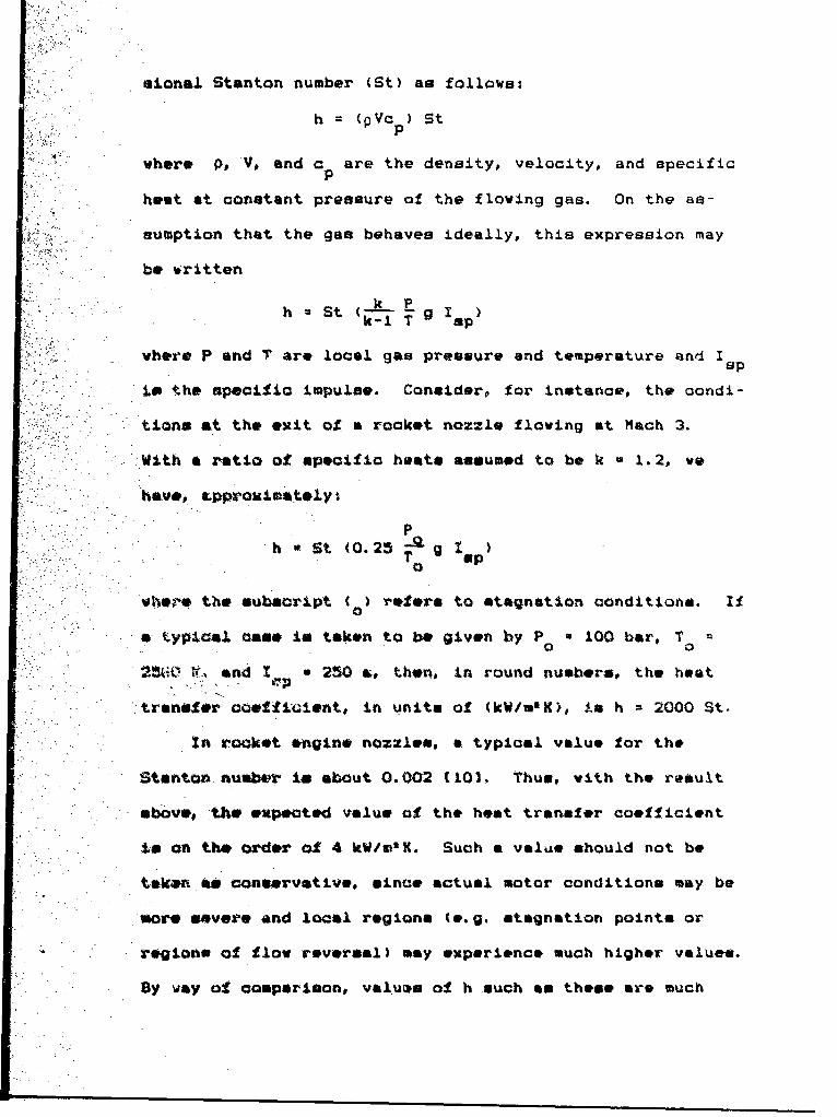
sionaj. Stanton number (St) as follows:
h (PVc )StP
where PV, and c are the density, velocity, and specificp
heat at constant pressure of the flowing gas. On the as-
sumption that the gas behaves ideally, this expression may
be *ritten
h *St (-A-. E gIk-1 T
vhere P and Tare local gas pressure and temperature and~ I13P
ip the specific impulse. Consider, for instance, the condi-
tions at the exit of a rocket nozzle flowing at Mach 3.
ýWith a ratio of specific heats assumed to be k *1.2, we
haVe, aPProXiPAtWly I
Ph St (0.25-Qg I
T sp
wh*,zr4 the subscript ()refers to stagnation conditions. I
a typictl cas** is taken to be given by P 100 bar, T0
-*0 it ndI 250 &, then, in round numbers, the host
transfer coofftuient, in units of (kW/m'K), is h *2000 St.
In rocket engine nozzle*, a typical value for the
Stanton number is. about 0.002 1101. Thus, with the ra~ult
above, the expotOd value of the hest transfer coefficient
to on the order of 4 kW/.nK. Such a value, should not be
taknaif.& conservative, since actual motor conditions may be
*ore severe and local regions (e.g. stagnation points or
regions of flow reversal) may experience much higher values.
By way of comparison, valums of h such an these are much
Page 10
larger than those usually considered for convective heat
transfer arnd, in fact, they are more typical o± those real-
ized in phase-change processes Ell).
II. MODELING AND SIMULATION
Backg~round
A general goal. of jet vane heat transfer studies in to
develop a capability by vhich the transient thermal behavior
of the vane may be predicted with confidence. An under-
standing of the energy transport processes occurring at the
boundaries of the vane is, of course, essential to the
aeti~vemmft of thiz goal but, because of the complexity of
the thormolluid environment in which the vane operates, CFD
nothads cannot be expected to yield a complete and compre-
-hensive predictive capability. In addition, the results of
CPD modeling must invovitably be simplified if they are to
be adapted to vane design purposes and the prediction of
systes performance. In order to complement the CFO studies,
therefore, a program has boon initiated to approach the
problem from a less-goererl but morm,-preoticsl point of
view. Uaderlying this approach is an acceptahce of the fact
t.hat detaila of the energy transport processes will never be
fully defined. On the other hand, there in also the recog-
nition that the cumulative or Olumped* effect of all the
various complications mentioned above is to transfer energy
to and trom the vane. These boundary processes lead to
further energy flow within the vane that ultimately gives
Page 11
rise to a vane temperature distribution that varies with
time.
This transient behavior should reflect the nature of
the boundary heat transfer processes that drive it, as well
-as the thermal impact of various vane design parameters
(thermal. conductivity, heat capacity, density, geometry,
"etc.). The transient response is the *signature" of the
"combined effects of the thermal environment and the vane
configuration. This premise is the basis for justification
of the modeling and simulation (ILS) study described in
subasequent aections of this report.
The goal of the U&S study has been to develop a Onamig
model of vane hesting and cooling. If such a model can be
constructed* even though it is approximate,, then significant
benefits will accrue. For instance, miasured vane tempera-
tu.re histories can be umsd for dg•jj9 purposes sch as
para.metric system identiflcstion (PSI) whereby the model is
""mW to deduce what would have had to be true in order for
the observed temperature history to have occurred. Having
estimated the values of appropriate parameters, local teo-
...'poratures can be deduced at points in the van& structure
,vhere oai-ditions (accessibility, sensor survival, etc.)
preclude iesaure*ent. In addition, a truatvorthy oredt.vA
model voulds (1) reduce the occasions in which teoting is
required to verify tha effects of design changes, (2) permit
the extension of sub-scale test data to predict full scale
jet vane performance, and (3) indicate the design directions
Page 12
most likely to lead to optimum system performance.
The tt&S approach may be thought of as a vast simplifi-
cation of a numerical model that, were it possible to con-
struct, would lead to a successful predictive capability.
Whereas such a comprehensive model would 'r-reat the flow
environment of the vane and the vane itself in fine numeri-
cal detmil, the IlLS method assumes that Oulficier.t accuracy
way be obtained if the flow and %he vane are made up of a
-relativoly few thermal parts. An important product of the
ML&S approach 3.s the prediction of the time history of the
von*et~esue nImt this is what provides the vital
cluipi that or* used to estiustw the values of the model
Th# system identificitioo procedurew used in this atudy
fx*ý* thoao toamiliar to the discipline of automatic controls.
...the governing mathematical relationships con be cost in a
transfer-f unction or other systematic form (not itocemserily
linearlo then eseporisontol observations con he related to
the various parameter. of the model by &.,otea identification
Oethod*6 'In order for this procedure to be of value, hey-
evoertho safre-mentioned parameters must be related to the
physical qUantitiee af!ecting the thermal tranaport process.
The establishment of these relationship, is described in the
nexit section of this report.
Page 13
III. MODEL DISCRETIZATION
The model as presently configured considers only two
thermal energy input processes: forced convection at th~e
vane surface and stagnation-point heat transfer at the
leading edge. These procenses are driven by the filow atag-
nation temperature wviich is, in turn, derived from the
me~asured thrust levels by meansa of the rocket-motor bal.-
liatic characteristice. The rise and fall of the stagnation
temapersture is assumed to follow that of the thruat withoyu4
significeat dynamic ofiset. Io other words, the generic
product-of tha model is a sertew of functions that give
lacal-vane temperaturee in response to thru~st. (If thou*
functions were linear, they would have direct transfer-
function counterpartw.)
Several vane discrotizatiao sahemen have been, tested,
annd it hem boen founci that four Olumpfh are suf1lacient to
iodicate tho-e. nrral thoroal behavior of the vane% vane tip,
vane b~ody. shaft, and mount. This configuration leads to a
simplicity that is a necessary feature of the )A&S approach,
and results tP be described later ju*tify the use of such
atimple sodeio as design tools.
As a pr*liminary stop in the study, the actual vane
design of intorest to the Naval Weapons Center was confi-
gured as a clleotioh of lumps with geometries suit~able fox-
estisation of thermal conduction properti..z. Figure 1 il-
lustrates the vane geometry that hom been modeled (the vane
Page 14
10
SCALE
(INCHES)
Fiur 1 Nva 7eapons Center jet vane configuration.
Page 15
in constructed of l0%Cu/W, and the mount material is a'e)
Fr-om this design, the fictiticou thermal. vane haa been
hypothesized as consisting of three rectangula'z solidst tip,
fin, and shaft. This discretized vane is shown in Fig. 2.
The tip of the vane has been separately identified in order
to account for the stagnation properties of the thermal can-
vection near the vane leading edge. Thia portion has been
arbitrarily sized so an to havo a chord length of 10% of the
total vane chord of 3.75 inches. With this length fixed,
the discretized tip is shaped so an to have the same lateral
area (chord x thickcneon) an that of thr;, actual tapered and
rounded tip.
The remainder of the dimopretizod fin in assumed to be
subjected to-thermol convection of a turbulent boundary
layer type. It in lumped into a rectangular solid of thick-
nne.s equal to the avierage value of the tapered fin (with tip
.removed) and span equal to the mean spen of the actual tin.
The ressiaing length dimension is met by equating the volume
of the rectangular solid to that of the fin (loes the tip
por~tion). The vane, shaft is similarly mmoldpmd" into a rec-
tangualer wolidi. and this element is assumed to be subjected
only to camduction (and radiation, were it included) heat
The vane *ount (not shown in Figs. I L 2) is a rele-
tively massive and complex structure. It order to pursue
the basic fe~aibility ol the method, no attempt was mad, to
model the thermal resistance of this component in detail.
Page 16
12
- - - -- - -
SCALE
(INCHES)
IFI
SHAFT
Figure 2. Diaczretized version~ of NWC Jet van~e-
Page 17
I~nsteabd, repr.?sentative sets of values (conduction lengtn
and crone-section) for the main mount components were esti-
mated using a rough scaling procedure. The appropriate
thermal. resintance of the mount was then computed from an
a'ia~yr±q of tlie analogous electrical circuit. En preimii-
daa.y BtuJies the mount thermal resistance was considered to
be an "adjustable parameter* for use in seeking agreement
"~it*- tbe tvsa.letlo experimental evidence. (Determinat~ion of
the correct value of this quantity i8 one of the goals of
the saystem identification procedure described later.)
4 ,ac~h of tho c- ,apc,.tents described above was assigned a
theiuaL. no-de located 2t lt's %uise-center which, in turn, is
-the aaes-wd-loc-tLn of the enrogv storage sresuoiated with
tth* entire, iass. Thb cap)acity to stir*e energy was calcu-
latod in the u01Usl way for- *aCh lump Por the mount, the
theratl ciapa-zi~.y was eotqu~aod to be in!4nito thus the
temperature of thias nad. remsinee co~nstant ftt ambient
(aCro'und.) tem~raltniur* during the eimulatiý_a.
* It *hould b. *aphaC±2ed thit at this p~aint in the study
:thQ dA-*ariz~tion rationale in Wait* ar'13itrary t' ~he goal.
hebo" -to, obtain adequat& agreement *a...:h toot reculta
Vairig the Amiaimum nusbwr of thermel 4oseon~enta. Refinement
-of the mondl con *autly.in-cludo tAo divivion of the vane
''tructure -into a larger number -it smaller "Itimps.* Altnough
thim would persit the estimation of tempera~ucoo at more
ftodou and interf aces, the accuracy cd theme wstifiates would
be no greator than that associated it~n the *minimum nodel
Page 18
14
model. described here. Such added complication of the vane
nodal. distribution would only be justifiable in conjunction
with a more-detailed description of the thermal boundary
conditions, and this would add even more uncertainty to the
* ~model. Results described later in~dicate that such
complication in not necessary.
Development of the Governing Eguations
With the thermal network and associated properties thus
-defined, the governing equations were formulated by means of
an energy balance at each node. In general, this balance
reada to- Mebofhat flow in =rate-of heat flow out rate
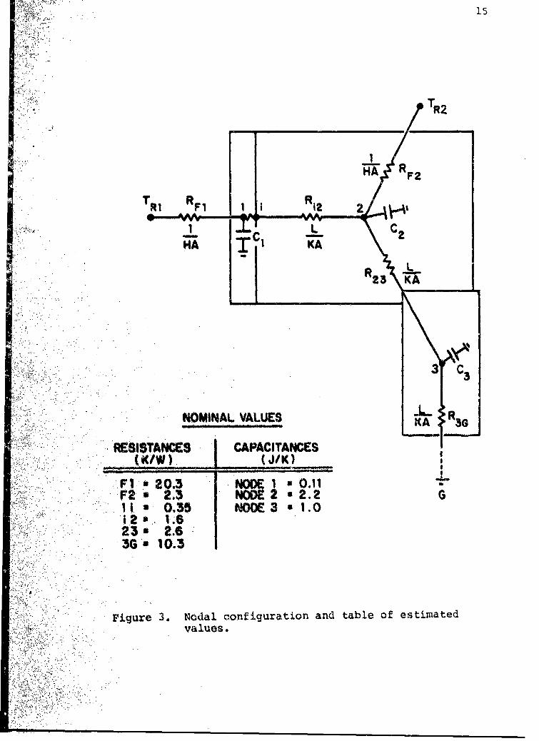
of energy y-torit.aw. For the fin node (node 2 in F~ig. 3), for
T -T T~ T T2 T C?(t1 22 3 Caf~ 2t 22
F2 2 23
..... r.. -hsymbol R is used to donate thermal resistance-
1/hA for convection to the tin and L/kA for conduction
between the nodes -- and C in thermal capacitance (mass x
heat capacity).- The letter a is, as usual, the symbol for
the Laplace variable. Calculation of the recovery temper-
eoturv. Ti is disousmu-d in the next section.
The temperature, at the node may be expressed explicitly
in*f ter," Cd the surrounding nodal temperatures an follows%
'N21 T T3T n2 (2)2 +~r R 2 Ri R
2 P 12 23
where ~the nodal resistance Rn Is given bys
R R2 R2
Page 19
15
TR2
HA KRi F2T R1 R1 I *
2
~ZTNA VALUE
Fl~~~~~ C23NC1 01 -
11a 'NOMINA VALUES .
AA 3
F1gr 203 Noda cn Igrto an taleo.etma1
.11. 0*3 valu3es1.
2 1.6
Page 20
and the nodal time constant is given by
It2 Rn2 C2
Hodes of the model that do not provide an energy storage
function are also absent the associated time constant. Thus
the temperature at the internal node shown at the interface
between the tip and fin of the present model (node i in Fig.
3) isexpressed in terms of the temperature of the surround-
ignodes with only thermal resistances as parameters.
A heat balance at each of the remaining nodes yields
r olationshipe similar to those given above, so sufficient
information in available to determine each nodal temperature
as a function of time. Initially, the system is assumed to
be at,`+,hermol equilibrium with the environment so that the
nodal tweper~turoo are all equal to the ambient Val e. With
the firing of the rocket motor this equilibrium in disturbed
:and: the two -recovery temperatures provide inputs to the
ensuing heat transfer process. In preliminary studies the
Digital Simulation Language (0S80 has been used to outomati-
colly saccomplish the repeated inte~gration steps required to
determvine. the thermal response of those nodes possessing
..storage capacities.
'The c~alculation method, together with preliminary
results,, or* described in later ovations. Before this,
hovoem . it is necessary to estimate the driving functions
St?.,e entire prooess -- the thermaI inputs at the tip and
I in surfaces. This is the subject of the next chapter.
Page 21
17
IV. ESTIMIATES OF SURFACE HEAT TRANSFER RATES
As described ini the previous section, the forcing func-
tions of particular interest are those due to heating at the
vane tip and along the downstream surface of the vane. (The
cooling effects of radiation and ablation, both clearly im-
portant in the actual situation, are omitted from discussion
for the time being.) Most of the heat transfer computations
outlined below are derived from the analytical methods sug-
gested in the works edited by C.C. Lin E1.21 and in the AGARD
Monograph authored by Ziebland and Parkinson 1103.
.A*particuJlar feature of these high speed fl~ows is the
Lorge difforencou in temperature that the gas experiencee in
de~eatn -near the body surface. nmc ae ti
neceossry to account for the twoperature dopvndoncy of gas
properties. A most-useful aimplification for this purpose
is that proposed by DiossLer and others C12,.p.3041 in which
the, Prandtl riuwber and specific heat are considered to be
oonstant inasmuch an their variations with temperature are
o~f a lover order of magnitude than those of the other gas
properties-(viscosity and thersal oonductivity). Thus, with
this ssoumptionp the quantity Pr/c constant and a separ-
ate estimate of the gas viscosity leads to the thermal
conductivity for a given Prandtl number and specific heat.
F~or the rough calculation* used in this study, the
Prandtl number has been estimated using the Eucken formula
420Z p.1391J, Pr -4k/(9k-5), wh~ere k is the ratio of specific
heat*. With the gas cons.tant, Rg the constant-pressure
Page 22
specific heat is given by c =R ki(k-1U.p g
In this work, the standard Sutherland-tp omi a
been adopted for determining viscosityi
T n
ref T ref
Following the recommendation of (2, p.9], a value of n 0.7
has been used. In addition, the reference viscosity has
-5 2been taken to be P4.040O H-s/m, at T 1000 K.
Stg~ata _Point Heat Tranqfe~r
In the analysis of stagnation point heating, the solu-
-tion. to:the .boutudary layer equation requires an eatimat, of
.the local'fluid acceleration in the vicinity of that point.
vi~ tthe 'aso of uupormonic flow, this can be approximnated
upo th aaum-ion that Newtonian flow prevail* between the
-c.. -.boy wvaie muid the body and, (mme van Driest 11, p.366]),
6 v (du dx) *(.U/LD).8(P /P )(T 00/T a
N**tho:Ou~bscript- a roferw to freestream conditions, (a)
iie~te sag~m~io c~ndtiono* and (y) is for condition.
Id f~ti'ai ol :the norwal-whoock, The prodoure and tempera-
Uirip Z'Ittd in the above exproes Lone are known functions of
-the _%V&**tr&Aa Mach number.
With 8 thus'dotined,, the Stanton number may be computea
-00. the followinal
St 0.57 (BD/U) 0 *Pr 0 ~ go0 0 0
Page 23
Turbuloznt gjoundary Layer Convection
In high speed compressible flows, the an~alysis of ther-
mal processes is complicated by the fact that considerable
compression and viscous dissipation follow from the deceler-
ations occuring in the boundary layer. Thia leads to tern-
peratures within the boundary layer that are in excess of
t.hat of the freestream, and the driving temperature for heat
.transfer ts the so-called recovery temperature, TR Thus a
recovery factor 'a defined &a follows:
T -T
T T
Fortunatel~y# it has been found by many investigators that
the, reicovery factor masy be related to the Prandtl number in
A sieple way that in adequate for most purposes. For a tur-
'bolent'iboundary layer aessumed here), the relationship in
r- it Pri'.
A wore.-diffioult problem arises frolm the depiondency of
O~a proprtion upon temperature sine* In east canoe the
a~p~mtw *ir~enev temperature for this colculation
depondo upobn the wall temperature. This, in turn, depends
Upon the polerea~ce temporature. The relerence temperature
ii typically defined as t23
T 0 0.2.8T 0O.2 2 Trat VailR
The -proant oalculationo are baoad upon the saaiumption that
theve.ltomperature is adequately represented for this pur-
po.by. tho**oen of the racovery antd ambient temperatures..
'...,*volutastica of the validity of this assumption requires
Page 24
20
an iterative time-dependent calculation. In the system
identification work to be described, however, the convective
resistance is treated as a parameter to be identified. Thus
the experimental data lead to the deduction of the "effec-
tive' film coefficient and the detailed analyses described
in this section may not be necessary for design purposes.)
J, Given that the reference temperature for gas properties
4aeadequately deact-ibed, the gas viscosity and therm~al con-
*- ducttvity may be estimated as above. The Stanton nuimber for
tUrbulent compr-asible flowv is then given by Ell:
-0.67 -0.2St .0.0296 Pr Re
F'rov the expressions given above for the Stanton num-
bers, Itusoolt numbers and thermal resistances can~ be calcu-
isted tor the model components affected by stagnation and
bodiday V 4yer host transfer processes. It should bo noted
tkw h*, thwwaul resistances are sosi..-dependenti stagnation
point thormal resistance decreasme* as (seal&) and turbu-
lentbowiarylayer thermal resistance, is propportional to
-1 2.'(scale) The simulationse conducted in this study have
been of a 1/4-scale, vane, in order to provide a comparison
vith-avalalble ?4WC test dat.a.
-The inforsation necessary to provide values for tho
thermal resiateanne includes the froestream characteristics
at the location of the jet van& Hachso number, atagnation
tomporstuk'ev and stagnation preasure. The concept of the
p~~t model is that theme, quantities are determined troam
Page 25
S,22.
7the ballistic characteristics of the rocket motor. Accord-
ingly, inputs required for the simulation incLude the motor
chamber pressure, thrust, and characteristic velocity, and
the discharge coefficient and pressure ratio of the nozzle.
In addition, necessary propellant gas properties include the
ratio of specific heats and the gas molecular weight or gas
constant. Experimental values are preferred, to the extent
that they are available, but a considerable body of theory
exiots if analytical estimates are necessary.
Prom these quantities, the stsgnation temperature may
be calculatled as tollovos
"T CC r '•211/
where-.
C nozztle discharge coetticient (.934)d.
r 1k( 2 /k*l)(s/k13050.)
o choru-ctoriatic velocity (1512 r/n/)
R gas constant (318.5 / -K)
I.k tatio of specific heats (1.21)
tie numbers given in psrentheaeu are those presently in use,
mad lead to a stiagnation temperature of 2650 K.
From the motor nozzle pressure ratio Mach number at the
euit (*m"used to be that at the vane) is computed fromS....... .... -- 2 [(k )/k
aideLec.Ltn a no-zle pressure ratio of P /P 186, this0@
--eprsion gives H 3. 75. It is important to note that
the cotor chamber pressure must also be provided because the
..het transfer cslculationu for the vane require the density
Page 26
22
and hence the pressure in the freestream at the vane loca-
tion -- in the calculations presented here, the value of
P 15. 76 MPa has been used.
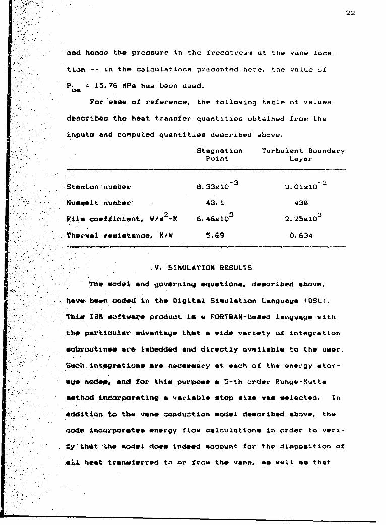
For ease of reference, the following table of values
describes the heat transfer quantities obtained from the
inputs and comiputed quantities described above.
Stagnation Turbul~ent Boundary
Point Layer
Stazaton number 8.53x10 3 3.01n103
Russeet number 43. 1 438
F~ile coefficient, W/ta K 6.46g103 2.25x10³
Thermalt resistance, 5f .69 0.634
V. SIMULATION IRSUL1S
The model and governing &quetions, described above,
havo bawn codeod La the Digital Simulation Language (OSL).
This tBSM saftware, pr'oduct isa~RRt-based language with
thw particaiuar. advantage that a wide variety of integration
oubroutinea or* tabeoddd and directly available to the user.
Such integrations ars, necoesary at each of the energy Stor -
age naod., and for this purpose a S-th order Runge-Kutta
method incorporating a variable stop size was selected. Zn
addition to the von* conduction model described above, the
code incorporate* energy flow calculations in order to yer-
* fy that Zh* model does indeed saccount for the disposition of
&aýl. heat. transferred to or fro* the vane, am wall me that
Page 27
stored at the various nodes.
The simulation code has been written so that the dri-
ving input is the thrust of the rocket motor, as provided by
test data. In the case reported here, the point-by-point
thrust vs. time measuremente are approximated by a ramp in-
put from 0 to 2335 N (525 Ib) in a period of 0.5s, held at
this level for 2.5a, and ramped back to zero thrust in a
further period of 0.5.. Although the actual thrust data
points could be used, the ramp-up/romp-dovn closely approxi-
notes the thrust schedule and provides a useful input for
evaluating the sensitivity of the thermal response of the
vane to various parameters of the model.
An ioportant aspect of the physi~cal event of rocket
-firing is that the conveotive reslstances to vane hoot
.tranaf.~ (at th�ue stagnotion point and in the boundary layer)
-eVe coupl•d to the presence or absence of flow psit the
--vano. Thuf th~aw realist~ancoa are initially very large,
dcraIoe rep.idly to plateau values as the motor reaches full
thrust, and increase again during burnout. This behavior
has been acdeled by postulating that the file coefficients
begins and *nd at 1% of the full-flow values and oiolov the
ramp-up, 1ieteau#, reap-davn profile of the thrust schedul,
For coa•p•rison with the simulation results, the vene
tempersture date were likewise converted to a continuoua
record by *ean* of the transfer function furnished by NWC
13.). This transf~er functon, which was deduced from the
test data, closely approaches the actual measurements and is
Page 28
24
given as
THRUST (1.233s+1)(50.76s+.l
(In this expr~iavion, thrust in Newtons gives a temperature
response in degrees Fahrenheit above ambient.)
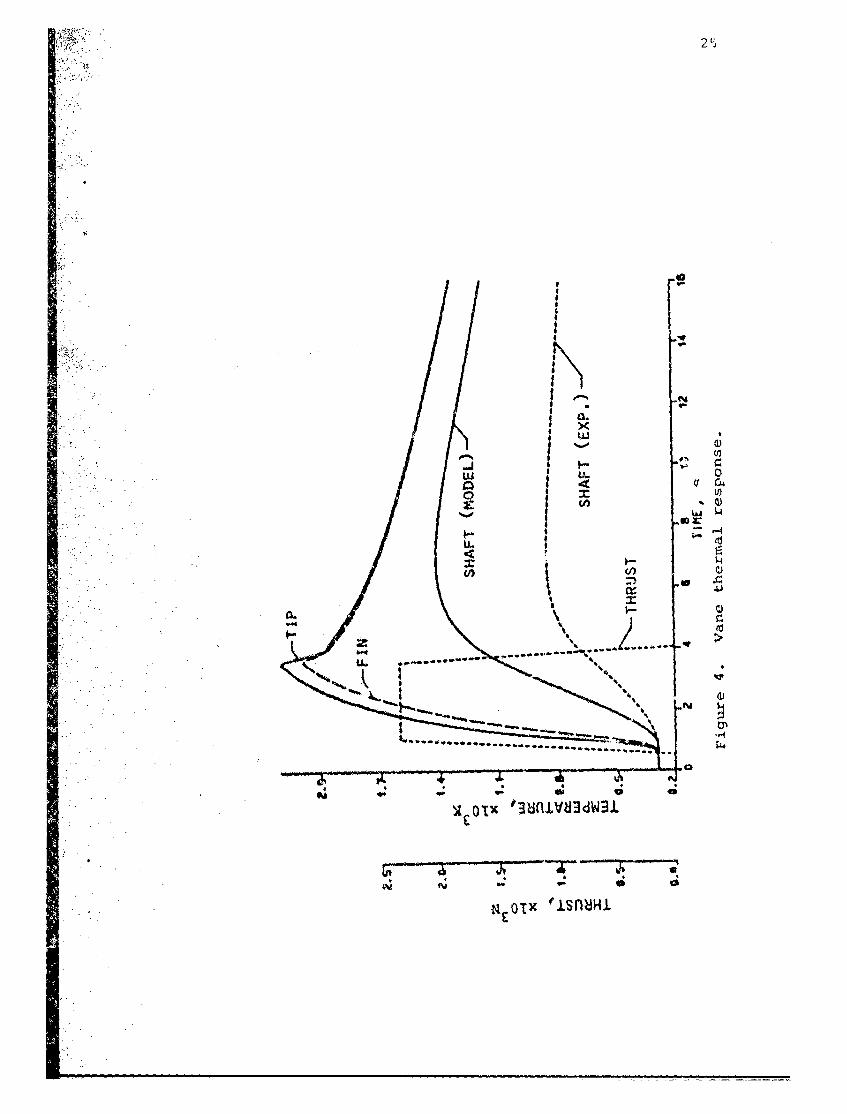
!iii. Vane Therm~al..Response
Figure 4 shows the computed vane temperature history
•:L. using Ocurrent best estimates- -f the problem parameters
described previously. This fi.; -e shovs that the predicted
temperature-time history r. the reference shaft node is well
in excess of that obtai.-ed in the tests.
In the model a it is presently configured, the quanti-
ties encuwbered by the greatest amount of uncertainty are
those associated with the boundaries of the thermal system
-- the convective inputs and the conductive cooling of the
vane by the thermal sink effect of the mount. Some prelimi-
nary experimentation with the simulation has led to the
insight that Yhý? chief control over the maximum shaft
temperature is the mount thermal resistance. On the other
hand, the dynamic temperature rise is mainly affected by the
convective thermal resistances acting at the vmne surface.
Theae observations lead to the pr*mia• that the effective
time conata.its for these two processes are widely separated
-- a clue to which is given in the previous transfer-func-
tion model.
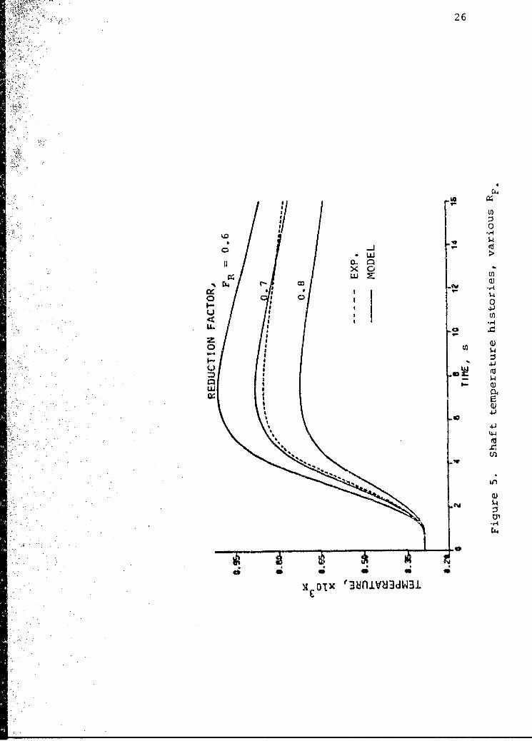
Adjustment of these factor,,, leads results of the sort
shown in Fig. 5. which illustrates the sensitivity of the
Page 29
o- 25
' 3;
I-
w. .
0 ' ="1 C,
-:'
z I
U.. *.
N ,
Page 30
~ I .26
x I,
0 ~ 00
-ILL 51
II 0..
1 ý4
41
o i*51~ 4 $4JI-44
440)
A olx"Univ~dW3
Page 31
27
shaft temperature response to the convective film coeffi-
cients. It will be seen from this figure that in order to
obtain reasonable agreement between theory and experiment it
is necessary to reduce these coefficients (with correspond-
ing increases in the respective thermal resistances) by a
factor on the order of 60% to 80% -- the ratio FR in Fig. 5.
The need for this offset is largely attributable to omission
of the cooling effects of radiation and ablation. It is
apparent, however, that the model in capable of reproducing
the main transient features (time constants) of the vane
thermal rewponae.
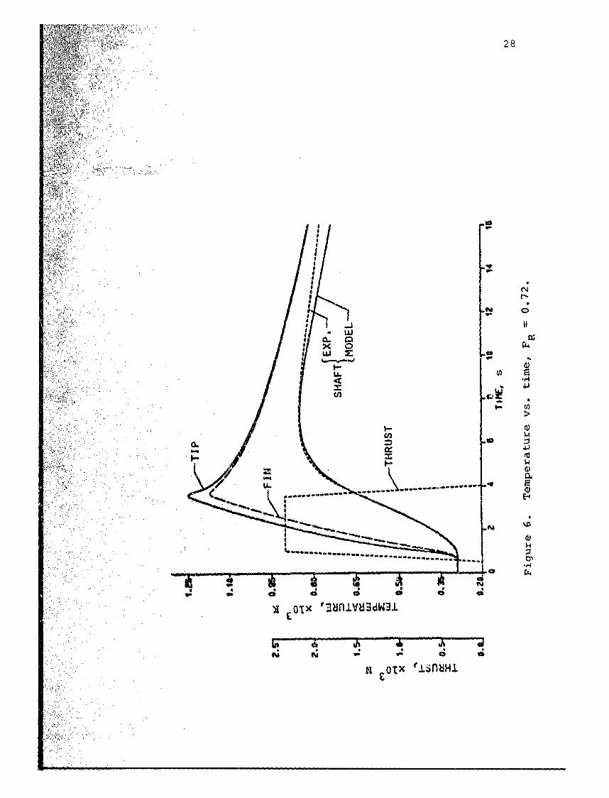
Figure 6 illustrates the sort of agreement with test
daet that is achievable using the present model. To achieve
.the resulto shown in Figs. 5 and 6presult, a mount thermal
resistance of. R 10.3 K/W wos used -- a value not incon-30
sistont with the ease and configuration of the mount. Whe-
*thor or not the reduction factor of 72% is consistent with
the effect of radiative and ablative cooling is yet to be
detertoined. In any case, it is noteworthy that the agree-
ment illuatrated in Fig. 6 in attainable by means of a sin-
gle constant lactor.
In adldition to providing the framework of a working
computational code, the results of the simulation indicate
that it way be feasible to predict the bulk thermal behavior
of selected critical elements . f the jet vane.. In order to
obtain these prelimina~ry results, no particular attention
has been paid to the precision with which the boundary ther-
Page 32
i.I - ,6
28
OPI
U..
U) c
E-. U
x o'rx V3bnlVU3dW31
£OIn;
R OU. LsnH.
Page 33
al. resistances are calculated. For the purposes of this
'V ork., the-simplicity of the mode! gives some encouragement
that it may be adaptable to the deductive or system-identi-
'fication mode of analysis. Preliminary results, reported in
A, AZ. u~sequent sections of this report, indicate that this is in
deed,.the case.
VI. STATE SPACE MODEL F'ORMULATION
The results presented thusfar have been obtained from a
sequential. integration of the energy balance relationships
at each calculation node, and Eq. (2) illustrates the form
irp which those relationships have been cast in the DSL pro-
grew for purposes of simulation. 1f the physical quantities
4resistancos and capacitances) appearing in the governing
system of equations are truly constant, then the system is
linear and the efficiency of a state space formulation may
be brought to beer. The matrix formats that characterize
-the state spwo4 larmulation are particularly useful in pro-
viding a eystwoatic presentation of the mathematical model.
In additto-no the following results have been obtained
using the per~oinsl computer version of the software package
oalled ONATRIAx* (product of Integrated Systems Incorpor-
ated, Palo Alfbo Calif.). Incorporated in ?IATRIXx is a vast
variety of matriu manipulation schemes that are often found
to be essential in the modeling and simulation of dynamic
systems (particularly control systems.) Included are means
for a~anveraion from continuous to discrete systems and for
Page 34
:~&>~C7Yrannforfuation of systems from state space to transfer f unc-
~ .. to oesadvc-versa. The system identification capa-
;biJJitie. of MATRIXx, essential to the goals of this study,
a'edisc44sed in a subsequent chapter.V31.
Mathematical relationships are expressed in state space
.~ L~. .. orm by arranging them such that tha& highest order deriva-
Stives of the dependent variables (the temperatures at the
various nodes, in this case) are given as linear functions
,of the lower order derivatives. For node 2, for instance,
(1 C) may be written
TTT 3 TR.2 C R R R ~ C R C R C R
2 F2 12 23 2i12 2 23 2 F2
Referring to Fig. 3# the corresponding re.lationships for
ýnodoe. and 3 are obtained:
T TA - T 4I C R C R C R
TT TT - .2 (..... .. ...L.. , 2
3 C R R C R C R3 23 30 3 23 C3 R3 0
The internal node designated (i) In Fig. 3, which was
included to allow separate estimation of the tip and vane
reuuts~eu isnot a storage node and, an previously noted,
*nergy balence for this node doem not include a rate termt
T T T -
* .L~..Z(6)R R
li 12
Eqiiation (6) may be solved for T and Eqw. (3) and (4) may
be used to obtain an expressioun f or its rate of chu~ge in
*the format of Eqs. (s)- (5). This would lead to a four-state
Page 35
formulaatlon for the four node temperatures. For efficiency
of. domputatlion# however, it seems good practice to eliminate
Ssuch non-storage nodes from consideration -~temperatures at
such nodes can always be calculated from algebraic expres-
-sian., such as Eq. (6), involving the temperatures at adja-
cent nodes.' Using Eq. (6) to eliminate T from Eqs. (3) and
()give. the fol.lowing 3-state not:
T 1T .. a. .~ (7)
-6 P1 R R12 C1 a12 C, R~.
T T T R2 1
T
3 CR C R R R3 23 3 23 30 3 3G
wher -0 R
. Arranged in much a fashion, it is apparent that the
nodal expressions possess a certain amuount of symmetry.
Eaoch'ot the coefficients of temperature on the righthand
simdes of Equ. (7)-(9) have the dimension of inverse time
and in fact, the RC products arw representations of the
time (3ponitents describing the energy transport process..
oQcouring at and around the nodes. To further illustrate
this ftwmi. C0I900"ft, it is uwsisuL to defiso the
following paraaeters (inverse time constants):
N-a +-( +b ab) 161/ R/ R
2L / 2 R12 a22 a-a2L + 23 +b22 a23B / 2 R23 (10)
31 2 323' 33 ( 3 1 ' 32 b33)
Page 36
*32
b 1/C R b 1/C R' b3 I/C R311 1 l 2 F 33
With tbype definixtions, Eqs. (7)-(9) may be written
W h*1po the "'state* conaists of the n 3 noda.l temperatures:
T (T T TI1 2 3
*i. nput* vector contains the m E3 boundary temperatures.
U, (T T TPRI. R2
an~d the nxa~ matrix A anid the nxm matrix B are given by
b 0 b1 0111 12 13 b21a2 a B o 0 b
a0l a b fto3 th32lyi~ 33] 33di teO
tquation (11) iexproesed in the.'utote-spaco form famil~iar
to h#-%~lyioofcontrols systems, an ttevector o
'inplt temperaturou are specified the time histories of the
n ~ odal. temperaturom or& easily obtained.
-Becosus the *ground* tomporoturc T' is a specified
aae~stant in1 this model (in the cesow at hand it is 290R) the
caloUlation may be oimplifteod by referring all temperatures
to igroukd this has the offect of removing the ground tomn
'poatare So an~ input (it is zero relativo to itself) and the
±input Vector becomes U_ (T T i.. With only tho recov-ri r2
ory tooperstur.. to inputs (a 2) the last columi~ in the
input Coo.-tticiont imatrix 11 is redundant and must be deleted.
_:MwThe thre. nodal tesperatures. are goutputs. * in a con-
trol oyotess sense, and the usual output relationship may be
vritt~n am
Page 37
zC,
X:C D U
w herve C is a 3x3 identity matrix and D is a 32*2 null matrix.
As a ,fiiiml step prior to simulation, the four matrices may
be combined into a single partitioned matrix, S. containing
the four submatrices A.. C. , and D. This is particularly
uselul when dealing with the !¶ATRIXx software. Thus
= ,or
a a~ a b 011 12 13 11a1 a a 0 b21 22 23 b22
a, Q (12)031 32 33 (21 0 0 0 0
0 1 0 a 0
*0 0 1 0 0
-~ this formulationi the thermal. characteristics of the
system aro~opcifiod in the &matrix and the input rosis-
tancem. are found in the elements making uap the amatrix.Note that tho 8iagormal elements of the ~.matrix are the
negative Invwreve oX the characteristic time constants for
the theuel rosponst of each of the nodes. As dofinod in
*q.(10), th#so diagonal elements ore, mums of the values on
U*i corresponding row, including the In~pu.t matrix. This
eaionobip emprossom the conservation of energy embodied
to the analysis and the diagonal elements cannot be indejpen-
-dently* varied without violating this principle. Thia is an
ivaportont constraint when *yet** identification procedures
are applied to th. system.
Page 38
The generality of the formulation is apparent, and
there would be no particular difficulty in adding storage
nodes to the model in order to obtain a more-detailed view
of the temperature distribution within the vane. Such
refinement at this point seems unwarranted, however, since
little information is available to allow a concomittant
reofinement of the distribution of the thermal inputs. In
..fact, the present model would not be drastically affected if
the stagnation point and boundary layer heat transfer were
combined into a single input, thus reducing the model to a
tvQa-eteAt system.
SIMULATION IN STATE SPACE
Figure 3 includes a table of the thermal resistances
iitad -nodal capacitances that have been *stitaated for the
prbles at. hand. (In ostimatingtheefci nu
r~x:Lt~ncva aivien'in F~ig. 3, the calculated heat transfer
Cotticionto~ have boon reduced by the 72%~ factor leading to
the result* described in the previous chspter.) When thee&
* alue. are, incorporated into the present analysis, the a. nd
m. atricoo take the following valueoi
18 0.(13023-0.61 0.18.
Par the tip node the input temperature in the stagna-
tion temperature 42650K) 6nd for the van* the recovery tem-
perotur* calcuLatied by tthe sothode of Ch. IV is 2550K (very
nearly the same, as the stagnation temperature in this high-
Page 39
speed compressible flow). When referred to an ambient tern-
pereture of 290K, the appropriate input values for tempera-
ture are
T' 2360K and T 2260KRI R2
Although the thrust was used as the fundamental input for
'the simulations previously described, these temperatures may
be assumed to follow an input schedule that is more-or-less
synchronous with the thrust. Accordingly, in the simula-
tiona that follow the recovery temperatures have been given
the some ramp-up, plateau (at the values given above), and
ramp-down contour that is described in Ch. V.
Lier -Tii.-r&simt LI)Mo
With the model matrices values given in Eq. (13) and
tho. schodulod input temperotures described above. simulation
of the- an* thermal response, is accomolished using the MAT-
R1X,1 LS1f dowmand C 14, p. 10-61. In this oust, the eyntax is
LTY. LS1fl(~,N%11 ,DCLTAT)
vher, g, is the *yet**m atrix formed a& in E-q. (121) and in-
ecorporoting tho volusa given in Eq. (13); HS is the number
of states (NS m3 -- the three nodal temperatures); ~[is the
input ara~ry,, in this case expressing the scheduled input
twespraturali~ and DELTAT in the specified time incropent
between ate"e in the V, array. In all simulation cases do-
a wi r1bod herein, a time increment of 0. lm has been used for a
duration of 15s. Thum the time vector has dimensions 151kI
and the array is 15lx2 for the two inputs..
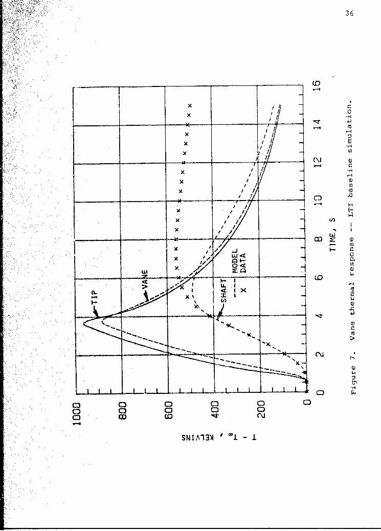
Figure 7 shovs the results of the simulation assuming
Page 40
36
)C I 1 E-4
> II
II
x IIec
~~I I
x U
__________ ________(NJ
SNIA-1-4
Page 41
that the elements of the and B matrices are constant with
ti.me. As expected, the results are unsatisfactory because
the linear t.ime-invariant (LTI) assumption does not account
-for the variation nf the heat transfer coefficients with
time. In other words, the elements of the B matrix and the
diagonal elemomets of the matrix must be calculated at each
time stop in the simulation.
LingEa Tim -VArIgnt (tLTV) Mo~del
ýWith MATRIXx, the accomodation of time-varying parame-
toer may be relatively easily achieved by using the SYSTEM
-BUILD capability. SYSTEM BUILD pý,ovidvo an interactive,
Aenu-dr'iven graphical environment for building, modifying,
and editing 4domputer simulation models. Any combination of
litior, aoft-linear,. cwontinuoue-time, diacrete-time, or Mul-
ti-rioto models that doscirib# a syet&* may he constructed
-fraw a. -library a$ basic building blocks. System* may be
eaddesd by dividing thou into individual components with
eath-ocamoes bein described by a apecific type of func-
ýtiona'. bl~ock.. S-upor-blooke can be used to represent a*-
Sewwblies of Individual blocks and the heirarchica). design
provides on orgsol±3ed representation of the physical system
that to modeled,
In SYSTEM BUIJLD. any supor-block or not of nested au-
per-blocks can be siaulated, linearized, and analyzed. No
user c~oding is necoesary (altho-igh it is allovod), and SYS-
TEK BUILD con be d1riven by user-defined command procedure~m
that automatically build or modify system models. All of
Page 42
this capability is available for PC hardware (which has been
vsed thunfar in this study) and the net effect of the SYSTEM
BUILD capability is that the user may concentrate efforts on
desigai, analysis, and simulation in an efficient graphical
environment.
Th YTMBIDMdl In this study, the vane ther-
mal behavior has been modeled by means of seven super-blocks
named as follows:
NOD.IIN, NOD21N, NOD3IH
NODE1, NODE2, NODE3
VANES
The appendix provides illustrations of these super-blocks,
and a brief discussion will be provided here.
The lirst three blocks are compute the parameters ne-
'cessary for the stat. equatic~n. The input to both NODIIN
and M0D2114 is the ramp-up, plateau, ramp-down schedule pre-
vioumly described, but with a plateau value of unity. In
NODiII4p for example, this input is multiplied by Ti andb
as gains to form the time-varying element in the first rov
of the input coefficient array Also in t4ODIIH, the quan-
tity a -,in generated by meana of the stop function undI 12
this, in turne is used to form -a a, + b as given in11 ý2 11
Eq. (10). The outputo of NCDIIN are -a,, , blIT~h and a 12'
NOD21H and MOD31N are similar in function, with the excep-
tion that MOD31H does not require thq time-varying input.
The first three super-blockcs listed above are elements
of the necond three, respectively. In NODE1, for example,
"L&AMVWr k\TiWrI X ýfX
Page 43
the external input T is combined with the outputs of NODIIN?
to forma the quantity a 1T1 + a12T +b T T An inte-11 12 2 1 Ri 1*
gration is also within NODEl to obtain Tfrom T is
the output of the NQDEI. super-block and, in a similar way,
NOOE2 and NODE3 provide outputs T' and T2 3
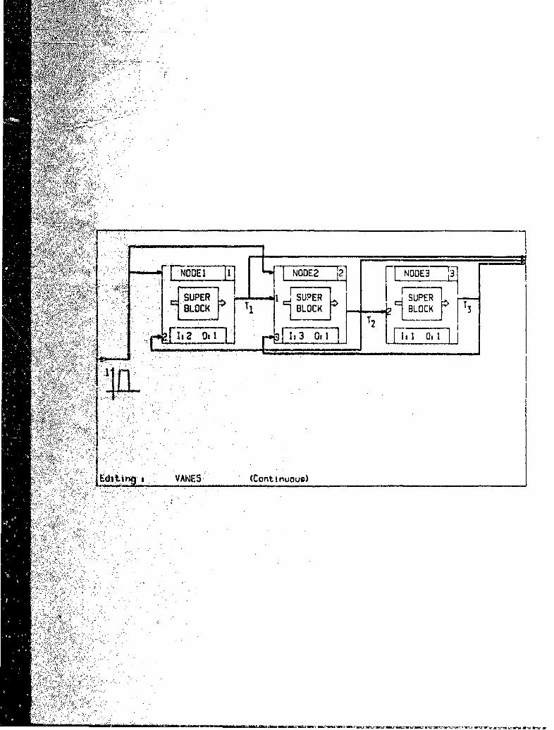
Super-block VANES *wires* NODE1, NQDE2, and NODE3 to-
gether in order to provide simultaneous solution for the
three nodal temperatures. In VANES (see appendix), NODEI
recei.ves thne dual ramp input and Twhile generatingT
NODE2 receives the dual ramp input, T,, and T3 while gener-
ating T and MODE3 receives T 2and outputs T
To execute the SYSTEM BUILD model, the program is first.
checked by means of the ANALYZE command 1151. Following
-this# one, of six integration methods may be selected from
the menu provided. The rout~lts described here have been
obt~ined-with a variable-atop Kotte-Ilerson scheme which is
.an explicit fourth-order method that omploys the largeat
t1%e stop posaible while remaining within error tolerances
(maximum stop mize is the time increment specitfl oU A h.I
Simulation is achieved by executing the SYSTEM BUILD
Cooi*sad Sf1, as in aSIM(TU_), where the time vector T
ad-tho input mu sut be provided. In the come at hand, T is
the I-Slul vector containing 15 seconds of 0.1-second steps
and JA is the 151x2 array exhibiting the ramp-up, unity pla-
teau, reap dovn schedule, proviously described.
Figure 8 shows the results of aimulation using the
Page 44
40
*,D
T II
LL I
I .,A
-3 M
SNIA'3 *I
Page 45
SYSTEM BUILD model to provide linear time-variant (LTV)
behavior of the vane heat transfer coefficients. In this
figure the improvements attained vith the SYSTEM BUILD LTV
model are apparent. With the model now cast in this form~at
it is possible to take the system identiiica..ion approach
that has boen the ultimate goal of this study.
VIII. PARAMETRIC SYSTEM IDENTIFICATION
The philosophy of parametwric system identification
(PSI) is to use measured response data to *massage" the
parameters of a system mcodl such that simulation results
ýmatch .those of experiments. Some of this has already been
accom lished by the manual variation of parameters described
*in Ch. V# but PSI will nov be used to complete this process
in a systematic vay.
In the problem at hand, it is reckoned that the most
uncertain parameter values are those associated with the
ýhoat transfer processes at the vane surfaee und the thermal
svink effects of the vane mount. Th* vane tamporature to be
satchod is: -that of the, shaft (T 3) and although the stegna-
tiotn hoot transfer process at the vane tip has been modeled
this provides relatively little heot flux into the vane and
ia therwicor of secondary importance an far as the theruali
~**pone& at the shaft is concerned.
Thum th&o results described here have been obtained by a
tvo-porameter variation involving b2 and a *It in to be
recalled that the variation of b2 will olso require a
Page 46
change in a2 in accordance with the energy balance, and
that this is accomodated in the SYSTEM BUILD model. In ad-
dition,-the value of a 3 has within it b which is not used
in the simulation since the relative ground temperature is
"""Rve-zero. Nevertheless, a knowledge of a will lead to the
appropriate value of b3 since b a a&3-3 as given in33 ~33 33 2
.Eq. (10).
'Th MTR~xPCfamily inldsa variety of capabili-
%' ties that-provide for data analysis, parametric and non-par-
'metric system identification, and digital filtering. In
Athis. ..ork, PSI is achieved by using a scheme known as Omaxi-
ýMum likelihood estimation* M~1E) [16]. As its name implies,
~L. aaimiesthe likelihood of the parameter estimates
given the observations (in this case, the measured transient
rapT~n so of T3) tLE operates on an entire time history
torat ar. than, ono sample at a time) and is applicab~le to
mnultipl :inplht/mlujtiple-output 011110) systems such as that
4or,- oop~slyui here.
The caomand that. exoautos the tIATRIXx version of the
-~proce~dure. in IIAXLIKE E03~, with the following syntax%
A YHAI',P2 MAXLIKE(I1JT3,PO, 'V8H2',NIT)
-tsato bo providod by the user are U containing the time
vector. and array of input coofficiental T3, the vector of
.ýobaorjvd values that are the standards for comparison; PO,
the vector of initial estimates for the paremeters to be
-veried;'V8H2V, a user-supplied command file that creates the
value* of T3 based upon !I and the current values of P; and
Page 47
NIT, the specified number of iterations to be performed.
The results of MAXLIKE are YHAT, the system response
uing current values of the parameters; P, which contains
these current values; and RSS which is the sum of the
;.squares of the differences betw~een the measured and pre-
:':~4 ~2..jdicted values at~each time step -- SS sum(T3 -YHAT)
'As has been shown, the LTV nature of the vane heat
transfer problem requires the use of SYSTEM BUILD. Thus, in
'`.the-problem at hand, the command file 'VBM2' reads as fol-
BUILD, EDIT, NOD2IN, 0,EXAMINE, 2, NEW,P(I), DONE, TOP,...
* . ~~EDIT, NODZ3IN,0, EXAMINE, 3,NEW, P(2), DONE, TOP,...
ANALYZE, VANE5
"R~ETURN
ý,AItho~qh this language may not be familiar to the reader, it
ima be POusible, to deduce that in the SYSTEMI BUILD lexicon
t~~einstructiolls sequentially update P(l) (a b )which is22
.4n osition*2 of euper-blooik NOD21N and P(2) (a a~ which
-in in poadtioa 3 *of super-block HOD31N. Y3 in the name gi-
yenA to: tb~e three-temperature array obtained from simulation
uming the current-parameter values, PUl) and p(2), with YHAT
Ca.)Tcontai.ned in third column. It should be noted that3
in~ each iteration the MAXLIKE procedure executes DVBM21 at
one* for each parameter value under consideration.
-Piguars 93 is the result of a PSI run of three iterations
Page 48
): .V -w
----------- _ __-
6.1-
f . 4
1 -4-)
IK -4
U) I
OKI
Q) -4
*1 ~ *I-1 O 4 1
uss/E!.
-W,. M >1".4.. 4 I>
.4 . 1 ,
x 'J O
I *'4-i Ul
1 ;v~ -
b --
Page 49
using initial parameter values given previously (b2 0.20
and a3 -0.48), The *maximum likelihood* values obtaitned.~. 33
'through the use of PSI, and giving the results shown in Fig.
9# are b2 0.2027 and a~ =0.4565. The value of the
residual associated with these results is RSS -59.4. (This
is a very small value, bearing in mind that it is a sum ol
* 151,squared temperature differences.)
DIgguagion of the PSI Results
As-was done, in Ch. V, the experimental shalt tempera-
ture, data (shown am W's in Figs. 7-9) have been obtained
tram the transfer function provided by NWC. In -this case,
the temperature above ambient, in Kelvins, is given by
13 4.4
THRUST (1.233*+1)(50.76o.1)
where, sasbefore, the thrust has the dimension of Newtons
(go* Fig. 6). A *tate-space equiva2lent of this expresnion,
whih is **oily obtained by moons of the )IATRIXx function
SPOM.io
?L 6k u
[-0.8307 =.0.01601 uK aE .76
00
an ~~ . (In this %-*presentation, y is the shaft tempera-
turoe 3 nd u to the thrust.) In the combined matrix format
previously discussed in connection with Sq. (12), these ma-
Page 50
F0.6307 -0.0160 1S1 0 0j()
The agreement illustrated in F'ig. 9, which is clearly
excellent, can be evaluated in several ways. For instance,
~; the temperature response resulting from the identified sys-
tem-may be cast. in a form that is directly comparable with
.that provided by NWC. To accomplish this, the system model
may be converted to the 2-state matrix form given above, and
"the three parameters of P. subjected to system identifica-
ion#w~ This has been done by means of the IIAXLIKE procedure
with the following reaultz
[0.8218'-0.0173 1
0 0.0716 0
with a value of RSS 63.4. Comparison of this result with
Al.s~) d**Qns~trates the agreement. Using 4.ho TFORM com-
:wand -of H4ATNIXx, the state-spaco representation may be con-
Verted-back to transfor-function form, yielding
THRUST (1.2t$0s.1)(46.08s.1)
oomporing vith Eq. (14) tho agreement in, again, remarkable.
Thit resoor should beer In mind thdt these arguments are made
hot, -iriy or ho pupos ofdemnsratng heeffectiveness
a~the 11,9 proowdurc in this case. The various transfer
tunations and parameters in these models have no relation to
the phynicsl situation - in fact, skince they r-epresent LTI
.syses they'are vholly inadequate for any purpose other'
theA'Ouproessing the experimental moasurements simulation
Page 51
results in functional forma.
Several sets of initial values have been used in iden-
tifying the parameter values in the physical model, and the
results have been found to be independent of this factor.
In addition, a number of testa have been performed to deter-
mine the effect of vahrying other parameters in the system
model and ro significent improvement has been obtained on
*the results illuatrated in Fig. 9. The seloction of the
approprista parameters to vary in the PSI process requires
Sm*t a-ppreciation for the physical proceusn modeled. Thus it
how been observed, for ina-tance, that the selection of too
-mony porramtt~ro will lead to unrealiatic values, such as
:.t4*Vtiv* thermal conductances, unless constraints are added
to th# MUMLIC procedure& These and other aspects of the
.Mithad 'or* uander continued study.
IX.. CONCLUS-IONS ARtD RECOMMEN~DATIONS
Thir #ephosis in the work reportod here has boot~ to in-
*veOstigate the fosmibility at using system idontificstion
mothiodo to develop tools tor use in the design of jot vane
TVC devices. A*Iore proceeding to conclusionse in this
refsa4.. MhOev&er it may be useful to comment on the rosults
,9ý Okbtbift" In the Cana that has boen analyzed.
Igeultl Of. thet AnslysMil
The oxccllent agreement between "asoured and predicted
she-It temperature responses shown in Fig. 9 gives some cre-
dibillty to the model parameters used in the simulation.
Page 52
Thesa. may 'L turn be related to vane physical properties to
lend some insights regarding those quantities that were
initially subject to relatively large uncertainties. For
the heat sink effect of the shaft mount, for instance, the
parameter b -a 3 - a may be obt.'dned from the identi-33 33 2
fied value of a -0.46 and the assumed (and relatively33t
certain) value of a3 0.38. The result is b 0.08 a32 33
and thlia may in turn be related to the vane physical proper-
-ies since b I/C R This new value ia down from the-'33 3 3G*
-original value of 0.10 8 (Fig. 3), and, since RC mcL./kA,
the result may be used to adjuat the rationale used in esti-
....... ratin~ the elfectivo mass and geometry of the thermal sink
-repr~aawnting' tha raount (assuming that the heat capacity and
thewaJl. conductivity are firm values).
Tho other parameter identified in the PSI analysis in
the Vanoe thermal input cowfficiont, b 0,2027 a if
* thigs .valvo is ua~d to rocalculate th'a convoctive heat tr~nQ-
'4t caoeficient# it value of h 6 38 W/ 2 K is ioltained which
isso~t72% lose than that estimated in Ch. IV for turbu-
lont bounadryt layer convection. The conclusion, an has been
is th-at the complex processes of ablation and
-radlatian account for a considerable amount of cooling of
tho Vae. It is important to keep in mind that the single
.Values. -quotd here arv useful only inasmuch as they give
:.gfoo4' oeults for predicting shaft temperatux' response using
tho~admol that ham been constructod. In this oase, the mo-
de. -include. a romp-up, plateau, ramp-down behavior forb
Page 53
so that the above result, which applies to the plateau value
of the *effective* heat transfer coefficient, accounts in a
crude way for the fact that vane heat transfer effects vary
widely throughout the firing. The assumption of a constant
pl-ateau value for h is, of course, subject to question and
refinement if sufficient information is available.
-Referring to the vane surface temperature responses
shown in Fig. 9, it is setan that a maximum of about 1240K
(9OK above ambient) is reached at about 3.5 seconds (3 se-
condo after motor ignition). This value is well below the
molting noint of the vane material) and the tensile modulus
is ti1 about 22,000 kei at this temperature (though it is
)tfoll beolw the ambient value of about 45,000 kait). It might
'be prediated from thexe results that the i./4-ocale vlAne that
Ihae boon, WoeIed would remain tuor*-or-loso intact during a
£I1ri ng of the -typo that has. been simulated. A noteworthy
it.aturs.ol thase d~v~lapm~nte to that it would be a roei-
tively 't, splo eatter to simulate the thermal response of a
fU1-8dole -vane. Each of the parameters. in the present Mo-
del. is asonsbie to direct scaling procoduros such as thou*
thatbsv4ben given In Ch. IV.
T-h*.sosults thornier obtained in this study justify oome
Ocotfidenco that the thermal. behavior of the Jet vane can be
-4adOeld usi.ng a relatively simple and .traight-forvard model
SAW ~turo. But olthough the, structure of the model In well
dloflawd# savi of the values of the system parametorm neces-
Page 54
sary to maka the model *work" are subject to considerable
uncertainty. In this study the power of the system identi.-
fication method has been brought to bear in removing some of
this uncertainty. In addition, it is worth mentioning that
-the relatively new capabilities now available with software
products like MATRIXx have greatly facilitated these advan-
Future research in these areas is warranted from both
the modeling and system identification points of view. Us-
ing the'model that haa been developed here, or perhaps an
even simapler model (vithout the tip node), it in impo~rtant
to detert~ine if the good results obtained in the present
inatance can be expected in other casea. With this in mind,
tho results of other firing t.ests should be predicted with
th. model and further system Identification conducted if it
prove& to be necessary. Tho basic iaaup would be to dater-
u~ine-thi. robustness ior look thereof) of the present model.
F &rom the modeling point of view, a number of inter-
*st~ing questions remain of a more theoretical nature. The
.relationship between the complexity of the model and the
-*dequacy 'of otpein-±mntal comparison dot* is of somo impor-
t~snice. In addition, more realism could be introduced into
theo present aodel in an effort to determine the sensitivity
of the results to ouch matters. For instance, it might ý,e
poodible to introduce a multiple thermal input model that
-accounts for radiation and ablation.,ae wall an thermal con-
voc~tion. Othor elements of realism could be introduced by
Page 55
allowing for the temperature dependency of several of the
parameters now taken as constant. These include the thermal
conductivity of the vane material and the reference tempera-
ture used in calculating the thermal properties of the motor
exhaust gases.
Another aspect of the method that may lead to important
insights is that the initi.a and final thermal responses
seem to be somevhat uncoup.Led under the present circumstan-
ces. For e--t•pl•-the LTI response illustrated in Fig. 7 is
quit* adequate, during the initial phase. The implication is
that the inltial aina final transients might be used to iden-
tity pArticular parameter values under the assumption that•
*they: are time-ivrat I' this ve,ýe true, the handling of
hontliaosr behavloru, should this become ntiacessry, would be
S' "• 'gry tly tinql$ tatd.d
S....
at_. .
Page 56
REFERENCES
1. National Aeronautics and Space Administration, "SolidRocket Thrust Vector Control," NASA SP-8114, Lewis ResearchCenter, Cleveland, OH., Dec., 1974.
2. Kampa, D., A. Weiss, and R. H. Schmucker, "~MaterialProblems in Jet Vane Thrust Vector Control Systems," AGARD-CP-259.
3. Wirtz, D. F., "Preliminary Design and Performance Esti-mate of a Jet Vane Attachment in a Rocket Nozzle, " internalmemorandum 45701/DPW:cad, Reg. 45701-242-73, Naval WeaponsCenter, CA, 4 June, 1973.
*4. Leitner, A., *Thrust Vector Control Heat Transfer Model-ing,' NPSGS-86-005, Naval Postgra.duate School, Monterey, CA,1986.
~.Yu~selen, A., "Heat Transfer Modeling of Thrust VectorControl Systertis," MS Thesis, Naval Postgraduate School,Monterey,. CA, 1986.
6. Spence, T. M., *Applications o~f Infrared Thermography inConvective Heat Transfer,4 MS Thesis, Naval PcotgraduuteSchool, Monterey, CA,, March, 1986.
7. Nunn, R. H. aad K. D. Kelleher', 'Jet. Vane A{eat.TransqferModeling,* NPS69-86-010, Naval Postgraduate School, 11onter -ey, CA, Oct. , 1986.
8. Dulke, M. F., 'Heat Tranufar Madeling of Jet Vane Thrust.Vector Control (TVC) Systems#* M9~ Thesis, Naval PostgraduateSchool, Monterey, CA, D~ec., 1987.
9. Nunn, R. H., *Modeling of Jet Verie Heat-Tranater Chnrac-te'riatice and Simulation of Thermal Retspanee,' TTCP PanolW4, KTAS, Naval.i Postgraduate School, Kontterey;- CA, Sep.,1987.
1.0. Ziebland, H. and R. C. Parkinson, *Hoot Transfer inRopket E~ngines,* AGARD-At3-14a-71, AGARD, Sep., 1971.
11. Holman, JT. P., IetTngr.4th ed., Mc(3raw-Hill, HevYork, 1I6
12. Tr~jt t qvkw Ind HatTr mr., ed. C. C. Lin, v. 5,
-High Speed Aeronautiza and Jet. Propulsion, Princeton Univ.N Pra~i,1959.
.13. Private commun~tcatiori, Mr. Jolhn Bratcher, Code 3275,Naval Weapons Center, China Lake, CA.
14. Integrated Syetems Inc,, ONATRIlXx/PC Usor's Guide,"
Page 57
Palo Alto, CA, 1985.
1.5. *-- SYSTEMBUILD/PC User's Guide,* 1986.
16. Bore, JA.,Modern Control Systems: A Manual of
Degign Methods. Prentice/Hall Intex-national, EnglewoodCliffs, N. J., 1986.
17. Integrated Systems Inc., "SYSTEM ID/PC User's Guide,"Palo Alto, CA, 1986.
.... .
Page 58
Noi
APPENDIX
Diagrams of System Build Super-Blocks
Page 59
- '12
+
*6 FU 15JI ~GAIN 2
1 R I
SPR BLOCK
cl
aT
l l in t NODE'l (Contin~uous) ____________
Page 60
S23 S T23 4
GAAIN2
GAI
N0021 N (ContinuouJs)
XA,
Page 61
32
USI2 2 1 533 3
F GAIN GAIN
10 0~1::Fh :11:101
'Ji
~Editing I N003 I N (Continuous)
K
ij
"1dl- I ODE3 (Continvuo.s)
Page 62
'fg "In
-. .
~' NODE2 31F
6DE 1. 12
L Id ng VAE5(Cntnuus
Page 63
M,~Ii .
INITIAL DISTRIBUTION LIST
* No. Copies
R. Library, Code 01422Naval Postgraduate SchoolMon~terey, CA 93943-5100
2.- Research Adm~inistration, Code 012Naval Postgraduate School
M~onterey, CA 93943-5100
3. Chairman, Code 69 2~epartment of Mechanical Engineering
-'U Naval Postgraduate SchoolMo*~teroyi. CA 93943-5100
4.- Professor Robert H. Nunn. Code 69Nn 10Department of Mechani.cal EngineeringNaval Postgraduate SinhoolMooterey, CA 93943-5100
.P~rofeassr L-W. Chang, Cod* 69Ck..Dvpartmer~t of Mlechanical Engineering
Naval Postgraduate SchoolM~ontoy 3A9343-5100
6 Pofesc~K. 0. Kollehwr, Cod* 69Kk 1tDeportmont. of Wlech1r 1 Engineering
Navl PstgaduteSvhoolKcrntwrey#. CA 93943-5O00
7.Prof assor P.' Puccti Codo G9PcQeptkr~t~mwt of Keochanicaa1 Engineeri.ngN'aval Poistqraduatio SchoollMont~troY,. CA 93943-SLOO
S Praofestor D. Salinas, Cod* 69S&'Departiwn t of eohanical Engine~rirngNmvol oastgradusto.SchoolItibter'ey# CA 43943-5100
90 Pr-oio'0. Sauith, Code 69SmIDopartoont of Mechanical EngineeringN*4*1l Postgraduate, Sc~hooltionteprey, CA 93943-5100
10. Prbfes-sor A. Garb*, Jr.~, Cod* 62Gz-Departaent of Electrical and
*Computer EngineeringNaval Pootgraduate SchoolNonteroy. CA 93943-5100
Page 64
V 'JL
INITIAL DISTRIBUJTION LIST (continued)
,Qwr..i.~
;'X4 No. Copies
I~V I*. Professor H.Titu, Code 62Ts I.:Department of Electrical and
-Computer EngineeringNaval Postgraduate SchoolMionterey, CA 93943-5100
12.-Hlr. Arne Danielson, Code 32731 5
Naval Weaponse Center
Chin~a Lake, CA 93555
i~. tr.R. Dillinger, Code 3273 1.Naval Woopone Center
C. hna Lake, CA 93555
-14. Dofenea Technical. Information Center 2Camwron Station,Alexandria, VA 22304-6145
E.
'V .