NAVAL POSTGRADUATE SCHOOL MONTEREY, CALIFORNIA THESIS Approved for public release; distribution is unlimited SOFTWARE DEFINED RADIO DESIGN FOR AN IEEE 802.11A TRANSCEIVER USING OPEN SOURCE SOFTWARE COMMUNICATIONS ARCHITECTURE (SCA) IMPLEMENTATION::EMBEDDED (OSSIE) by Leong Wai Kiat Chris December 2006 Thesis Advisor: Frank Kragh Thesis 2 nd Reader: R. Clark Robertson
Transcript
NAVAL POSTGRADUATE
SCHOOL
MONTEREY, CALIFORNIA
THESIS
Approved for public release; distribution is unlimited
SOFTWARE DEFINED RADIO DESIGN FOR AN IEEE 802.11A TRANSCEIVER
USING OPEN SOURCE SOFTWARE COMMUNICATIONS ARCHITECTURE (SCA)
IMPLEMENTATION::EMBEDDED (OSSIE)
by
Leong Wai Kiat Chris
December 2006
Thesis Advisor: Frank Kragh Thesis 2nd Reader: R. Clark Robertson
THIS PAGE INTENTIONALLY LEFT BLANK
i
REPORT DOCUMENTATION PAGE Form Approved OMB No. 0704-0188 Public reporting burden for this collection of information is estimated to average 1 hour per response, including the time for reviewing instruction, searching existing data sources, gathering and maintaining the data needed, and completing and reviewing the collection of information. Send comments regarding this burden estimate or any other aspect of this collection of information, including suggestions for reducing this burden, to Washington headquarters Services, Directorate for Information Operations and Reports, 1215 Jefferson Davis Highway, Suite 1204, Arlington, VA 22202-4302, and to the Office of Management and Budget, Paperwork Reduction Project (0704-0188) Washington DC 20503. 1. AGENCY USE ONLY (Leave blank)
2. REPORT DATE December 2006
3. REPORT TYPE AND DATES COVERED Master’s Thesis
4. TITLE AND SUBTITLE: Software Defined Radio design for An IEEE 802.11a Transceiver using Open Source Software Communications Architecture (SCA) Implementation::Embedded (OSSIE) 6. AUTHOR(S) Leong Wai Kiat Chris
5. FUNDING NUMBERS
7. PERFORMING ORGANIZATION NAME(S) AND ADDRESS(ES) Naval Postgraduate School Monterey, CA 93943-5000
8. PERFORMING ORGANIZATION REPORT NUMBER
9. SPONSORING / MONITORING AGENCY NAME(S) AND ADDRESS(ES) N/A
10. SPONSORING / MONITORING AGENCY REPORT NUMBER
11. SUPPLEMENTARY NOTES The views expressed in this thesis are those of the author and do not reflect the official policy or position of the Department of Defense or the U.S. Government. 12a. DISTRIBUTION / AVAILABILITY STATEMENT Approved for public release; distribution is unlimited.
12b. DISTRIBUTION CODE
13. ABSTRACT (maximum 200 words) In this thesis, we present the design of a software defined radio (SDR) transceiver using Open Source SCA Implementation::Embedded (OSSIE) as the software platform. Designing a SDR requires both an appreciation of the IEEE 802.11a (wireless Local Area Network at 5 GHz band) protocol standard as well as the understanding of the C++ and CORBA software tools available to implement the physical transmitter and receiver layers. For this work, the Incremental Development Model was chosen, which is comprised of three stages: Design, Develop and Verify. The advantage of this model is its incremental nature, which allows the developer to learn from earlier versions of the system. Implementing the IEEE 802.11a physical layer using OSSIE requires a total of 23 components, 12 different functionalities and 31 sequential input-output (I/O) processes for the transmitter, while the receiver is implemented with 18 components, 12 different functionalities and 20 sequential I/O processes. The completed transmitter and receiver layers are validated successfully according to test cases stipulated in the IEEE standard.
15. NUMBER OF PAGES
138
14. SUBJECT TERMS Software Defined Radio, IEEE 802.11a, wireless Local Area Network, Open Source SCA Implementation::Embedded (OSSIE), C++, CORBA
16. PRICE CODE
17. SECURITY CLASSIFICATION OF REPORT
Unclassified
18. SECURITY CLASSIFICATION OF THIS PAGE
Unclassified
19. SECURITY CLASSIFICATION OF ABSTRACT
Unclassified
20. LIMITATION OF ABSTRACT
UL NSN 7540-01-280-5500 Standard Form 298 (Rev. 2-89) Prescribed by ANSI Std. 239-18
ii
THIS PAGE INTENTIONALLY LEFT BLANK
iii
Approved for public release; distribution is unlimited.
SOFTWARE DEFINED RADIO DESIGN FOR AN IEEE 802.11A TRANSCEIVER USING
OPEN SOURCE SOFTWARE COMMUNICATIONS ARCHITECTURE (SCA) IMPLEMENTATION::EMBEDDED (OSSIE)
Leong Wai Kiat Chris Major, Republic of Singapore Air Force
B.Eng, National University of Singapore, 1999 M.Tech, National University of Singapore, 2003
Submitted in partial fulfillment of the requirements for the degree of
MASTER OF SCIENCE IN ELECTRICAL ENGINEERING
from the
NAVAL POSTGRADUATE SCHOOL
December 2006
Author: Leong Wai Kiat Chris
Approved by: Assistant Professor Frank Kragh
Thesis Advisor
Professor R. Clark Robertson Thesis 2nd Reader
Professor Jeffrey B. Knorr Chairman, Electrical and Computer Engineering Department
iv
THIS PAGE INTENTIONALLY LEFT BLANK
v
ABSTRACT
In this thesis, we present the design of a software defined radio (SDR) transceiver
using Open Source Software Communications Architecture (SCA)
Implementation::Embedded (OSSIE) as the software platform. Designing a SDR requires
both an appreciation of the IEEE 802.11a (wireless Local Area Network at 5 GHz band)
protocol standard as well as the understanding of the C++ and CORBA software tools
available to implement the physical transmitter and receiver layers. For this work, the
Incremental Development Model was chosen, which is comprised of three stages:
Design, Develop and Verify. The advantage of this model is its incremental nature, which
allows the developer to learn from earlier versions of the system. Implementing the IEEE
802.11a physical layer using OSSIE requires a total of 23 components, 12 different
functionalities and 31 sequential input-output (I/O) processes for the transmitter, while
the receiver is implemented with 18 components, 12 different functionalities and 20
sequential I/O processes. The completed transmitter and receiver layers are validated
successfully according to test cases stipulated in the IEEE standard.
vi
THIS PAGE INTENTIONALLY LEFT BLANK
vii
TABLE OF CONTENTS
I. INTRODUCTION........................................................................................................1 A. OBJECTIVES ..................................................................................................1 B. GUIDING PRINCIPLES ................................................................................1
1. Start Small ............................................................................................1 2. Think Modular.....................................................................................2 3. Help is Out There.................................................................................2
C. INCREMENTAL DEVELOPMENT MODEL.............................................3 1. Design ....................................................................................................4 2. Develop..................................................................................................5 3. Verify.....................................................................................................5
D. THESIS CHAPTERS BREAKDOWN ..........................................................5
II. DESIGN ........................................................................................................................7 A. REQUIREMENTS ANALYSIS .....................................................................7
MODEL ..........................................................................................................15 1. Transmitter.........................................................................................15 2. Receiver...............................................................................................20
III. DEVELOP: TRANSMITTER ..................................................................................25 A. PREAMBLE...................................................................................................25
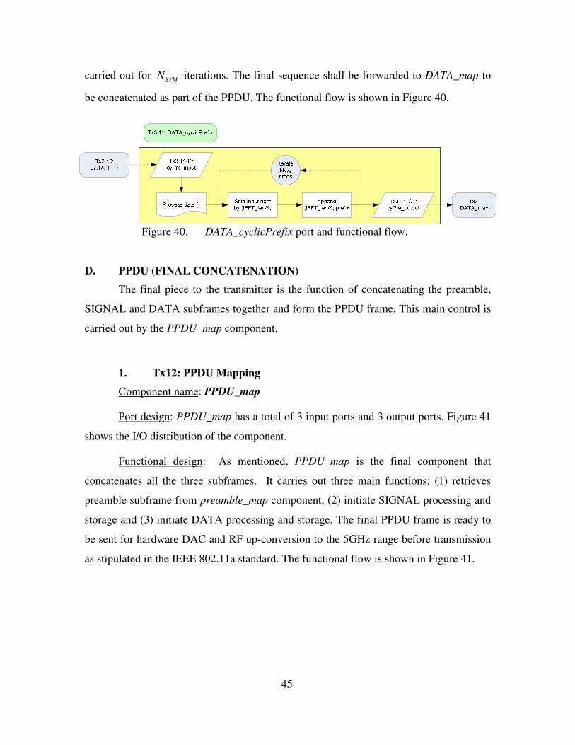
D. PPDU (FINAL CONCATENATION)..........................................................45 1. Tx12: PPDU Mapping .......................................................................45
IV. DEVELOP: RECEIVER...........................................................................................47 A. PREAMBLE...................................................................................................47
V. CHALLENGES..........................................................................................................61 A. SPECIAL INTEREST COMPONENTS .....................................................61
1. IFFT / FFT..........................................................................................61 a. Real to Complex Conversion ..................................................63 b. Bit Reversal .............................................................................64 c. DIT PINO DFT.......................................................................64
2. Viterbi Decoder ..................................................................................65 a. Initialise_viterbi()....................................................................65 b. Process_viterbi()......................................................................66 c. BUTTERFLY_viterbi() ...........................................................67
B. OTHER CHALLENGES ..............................................................................68 1. Data Synchronisation (Ports Management) ....................................68
ix
2. MIMO Components...........................................................................68 3. Control Variables...............................................................................69
VI. VERIFY ......................................................................................................................71 A. TRANSMITTER............................................................................................71
1. Preamble .............................................................................................71 a. Tx1: Preamble Mapping (Assembly Controller)....................71 b. Tx1.1.9: Carriers Mapping (ST).............................................72 c. Tx1.1.10: IFFT (ST) ...............................................................72 d. Tx1.2.9: Carriers Mapping (LT).............................................73 e. Tx1.2.10: IFFT (LT)...............................................................73 f. Tx1.2.11: Cyclic Prefix (LT)...................................................73
2. SIGNAL ..............................................................................................74 a. Tx2: SIGNAL Mapping ..........................................................74 b. Tx2.6: Convolutional Encoder (SIG).....................................74 c. Tx2.7: Interleaver (SIG) .........................................................75 d. Tx2.8: BPSK Modulation (SIG) .............................................75 e. Tx2.9: Carriers Mapping (SIG)..............................................75 f. Tx2.10: IFFT (SIG) ................................................................75 g. Tx2.11: Cyclic Prefix (SIG) ....................................................76
3. Data .....................................................................................................76 a. Tx3: DATA Mapping ..............................................................77 b. Tx3.4: Scrambler (DATA) ......................................................77 c. Tx3.5: Tail Replacement (DATA) ..........................................77 d. Tx3.6: Convolutional Encoder (DATA).................................78 e. Tx3.7: Interleaver (DATA) .....................................................78 f. Tx3.8: Modulation Mapping (DATA) ....................................78 g. Tx3.9: Carriers Mapping (DATA)..........................................79 h. Tx3.10: IFFT (DATA) ............................................................79 i. Tx3.11: Cyclic Prefix (DATA)................................................80
4. PPDU (Final Concatenation) ............................................................80 a. Tx12: PPDU Mapping ............................................................80
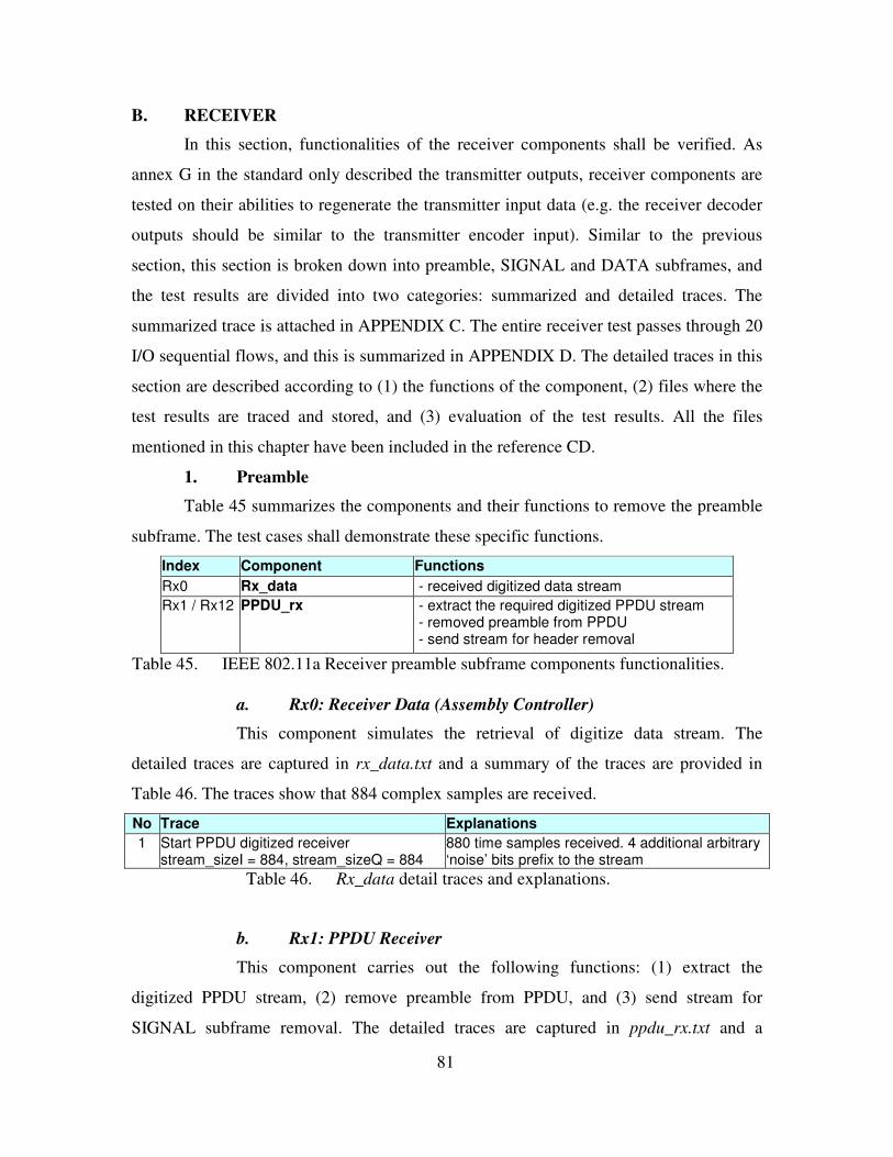
B. RECEIVER ....................................................................................................81 1. Preamble .............................................................................................81
a. Rx0: Receiver Data (Assembly Controller) ............................81 b. Rx1: PPDU Receiver...............................................................81
2. SIGNAL ..............................................................................................82 a. Rx2: SIGNAL Receiver...........................................................82 b. Rx2.11: Cyclic Prefix Removal (SIG) ....................................83 c. Rx2.10: FFT (SIG) .................................................................83 d. Rx2.9: Carriers Demapper (SIG) ...........................................83 e. Rx2.8: BPSK Demodulator (SIG) ..........................................84 f. Rx2.7: De-Interleaver (SIG) ...................................................84 g. Rx2.6: Convolutional Decoder (SIG).....................................84
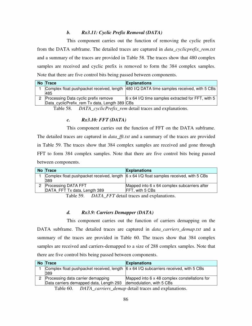
3. Data .....................................................................................................85 a. Rx3: DATA Receiver...............................................................85 b. Rx3.11: Cyclic Prefix Removal (DATA) ................................86
x
c. Rx3.10: FFT (DATA) .............................................................86 d. Rx3.9: Carriers Demapper (DATA) .......................................86 e. Rx3.8: Demodulation Mapper (DATA)..................................87 f. Rx3.7: De-Interleaver (DATA)...............................................87 g. Rx3.6: Convolutional Decoder (DATA).................................87 h. Rx3.4: Descrambler (DATA) ..................................................88
VII. CONCLUSION ..........................................................................................................89 A. SUMMARY ....................................................................................................89 B. RECOMMENDATIONS...............................................................................90
APPENDIX A: IEEE 802.11A COMPONENTS PORT TYPES.......................................93 A. TRANSMITTER............................................................................................93 B. RECEIVER ....................................................................................................94
APPENDIX B: GLOBAL PARAMETERS.........................................................................95
APPENDIX C: SUMMARIZED TRACE ...........................................................................97 A. TRANSMITTER............................................................................................97 B. RECEIVER ..................................................................................................105
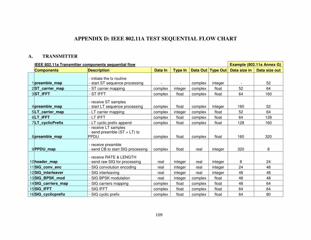
APPENDIX D: IEEE 802.11A TEST SEQUENTIAL FLOW CHART .........................109 A. TRANSMITTER..........................................................................................109 B. RECEIVER ..................................................................................................111
LIST OF REFERENCES....................................................................................................113
INITIAL DISTRIBUTION LIST.......................................................................................115
xi
LIST OF FIGURES
Figure 1. Incremental Development Model. .....................................................................4 Figure 2. Model of Software Defined Radio. ....................................................................7 Figure 3. PPDU frame format (from: reference [3], Fig 107). ..........................................9 Figure 4. Incremental conceptual design.........................................................................11 Figure 5. MATLAB BPSK transceiver model. ...............................................................11 Figure 6. MATLAB QPSK transceiver model. ...............................................................12 Figure 7. MATLAB OFDM transceiver model...............................................................13 Figure 8. IEEE 802.11a Transmitter components flow diagram.....................................15 Figure 9. IEEE 802.11a Transmitter subframes flow diagram........................................17 Figure 10. IEEE 802.11a Receiver components flow diagram. ........................................20 Figure 11. IEEE 802.11a Receiver subframes flow diagram. ...........................................22 Figure 12. PPDU frame structure and timing. (from: reference [3], Fig. 110). ................25 Figure 13. preamble_map port and functional flow..........................................................26 Figure 14. ST_carriers_map port and functional flow......................................................27 Figure 15. ST_IFFT port and functional flow. ..................................................................28 Figure 16. LT_carriers_map port and functional flow......................................................29 Figure 17. LT_IFFT port and functional flow...................................................................29 Figure 18. LT_ cyclicPrefix port and functional flow. ......................................................30 Figure 19. SIGNAL_map port and functional flow. ..........................................................31 Figure 20. composition of SIGNAL field (from: reference [3], Fig. 111). .......................32 Figure 21. convolutional encoder ( 7ν = ) (from: reference [3], Fig. 114). ......................32 Figure 22. SIG_conv_enc port and functional flow. .........................................................33 Figure 23. SIG_interleaver port and functional flow. .......................................................34 Figure 24. SIG_BPSK_mod port and functional flow. ......................................................34 Figure 25. SIG_carriers_map port and functional flow....................................................35 Figure 26. SIG_IFFT port and functional flow. ................................................................35 Figure 27. SIG_cyclicPrefix port and functional flow. .....................................................36 Figure 28. Composition of SERVICE field (from: reference [3], Fig. 112). ....................36 Figure 29. DATA_map port and functional flow...............................................................37 Figure 30. DATA scrambler (from: reference [3], Fig. 113). ...........................................39 Figure 31. DATA_ scrambler port and functional flow.....................................................39 Figure 32. DATA_ tail_replacement port and functional flow..........................................40 Figure 33. DATA_conv_enc puncturing patterns (after: reference [3], Fig. 115). ...........41 Figure 34. DATA_conv_enc port and functional flow.......................................................41 Figure 35. DATA_interleaver port and functional flow. ...................................................42 Figure 36. Constellation modulation mapping (after: reference [3], Table 82 to 85). .....43 Figure 37. DATA_mod_map port and functional flow. .....................................................43 Figure 38. DATA_carriers_map port and functional flow. ...............................................44 Figure 39. DATA_IFFT port and functional flow. ............................................................44 Figure 40. DATA_cyclicPrefix port and functional flow...................................................45 Figure 41. PPDU_map port and functional flow. .............................................................46 Figure 42. Rx_data port and functional flow. ...................................................................48 Figure 43. PPDU_rx port and functional flow..................................................................48
xii
Figure 44. SIGNAL_rx port and functional flow...............................................................50 Figure 45. SIG_cyclicPrefix_rem port and functional flow. .............................................50 Figure 46. SIG_FFT port and functional flow. .................................................................51 Figure 47. SIG_carriers_demap port and functional flow. ...............................................51 Figure 48. SIG_BPSK demod port and functional flow. ...................................................52 Figure 49. SIG_deinterleaver port and functional flow. ...................................................53 Figure 50. SIG_conv_dec port and functional flow. .........................................................53 Figure 51. DATA_map port and functional flow...............................................................55 Figure 52. DATA_cyclicPrefix_rem port and functional flow. .........................................55 Figure 53. DATA_FFT port and functional flow...............................................................56 Figure 54. DATA_carriers_demap port and functional flow. ...........................................56 Figure 55. Constellation demodulation mapping. .............................................................57 Figure 56. DATA_demod_map port and functional flow. .................................................57 Figure 57. DATA_deinterleaver port and functional flow. ...............................................58 Figure 58. DATA_conv_dec puncturing patterns. .............................................................59 Figure 59. DATA_conv_dec port and functional flow.......................................................59 Figure 60. DATA scrambler..............................................................................................60 Figure 61. DATA_descrambler port and functional flow..................................................60 Figure 62. OFDM transmission system: transmitter and receiver.....................................62 Figure 63. DATA_IFFT and DATA_FFT functional flows. ..............................................63 Figure 64. A sample signal flow graph of a DIT PINO FFT. ...........................................63 Figure 65. An example of Viterbi decoder: DATA_conv_dec functional flow. ................65 Figure 66. initialise_viterbi() functional flow...................................................................66 Figure 67. process_viterbi() functional flow.....................................................................67 Figure 68. BUTTERFLY_viterbi() functional flow. ..........................................................67 Figure 69. PPDU_map MIMO and control functional flow. ............................................69 Figure 70. Transmission of dynamic control variables. ....................................................69
Table 44. PPDU_map detail traces and explanations......................................................80 Table 45. IEEE 802.11a Receiver preamble subframe components functionalities. .......81 Table 46. Rx_data detail traces and explanations. ...........................................................81 Table 47. PPDU_rx detail traces and explanations. ........................................................82 Table 48. IEEE 802.11a Receiver SIGNAL subframe components functionalities. .......82 Table 49. SIGNAL_rx detail traces and explanations. .....................................................83 Table 50. SIG_cyclicPrefix_rem detail traces and explanations......................................83 Table 51. SIG_FFT detail traces and explanations. .........................................................83 Table 52. SIG_carriers_demap detail traces and explanations........................................84 Table 53. SIG_BPSK_demod detail traces and explanations. ..........................................84 Table 54. SIG_deinterleaver detail traces and explanations............................................84 Table 55. SIG_conv_dec detail traces and explanations. .................................................85 Table 56. IEEE 802.11a Receiver DATA subframe components functionalities............85 Table 57. DATA_rx detail traces and explanations. .........................................................85 Table 58. DATA_cyclicPrefix_rem detail traces and explanations. .................................86 Table 59. DATA_FFT detail traces and explanations. .....................................................86 Table 60. DATA_carriers_demap detail traces and explanations....................................86 Table 61. DATA_demod_map detail traces and explanations..........................................87 Table 62. DATA_deinterleaver detail traces and explanations. .......................................87 Table 63. DATA_conv_dec detail traces and explanations. .............................................87 Table 64. DATA_descrambler detail traces and explanations. ........................................88
xv
ACKNOWLEDGMENTS
I would like to express my gratitude to Assistant Professor Frank Kragh and
Professor R. Clark Robertson for their professional advice, guidance and assistance in
making this thesis a possibility in such a short time. Their patience in me is greatly
appreciated. I am also grateful for my organization, the Republic of Singapore Air Force,
for giving me this opportunity to study at the Naval Postgraduate School and carry out
this interesting thesis work. This one-year experience has definitely enriched my
knowledge in my professional and technical fields.
xvi
THIS PAGE INTENTIONALLY LEFT BLANK
xvii
EXECUTIVE SUMMARY
Reed defines a software defined radio (SDR) as a radio that can be “substantially
defined in software and whose physical layer behavior can be significantly altered
through changes to its software”1. SDR has distinct military advantages over
conventional radio as it promotes multi-functionality, mobility, compactness, flexibility,
ease of manufacture and ease of upgrades.
A military unit will not always know in advance what communications
capabilities it will need in operations. This is especially true in coalition operations,
where the coalition partner’s forces may not have the preferred radio equipment.
Therefore, in operations, it is imperative to be prepared for many different means of
communications, especially those that a coalition partner would be likely to possess.
Radio equipment built to commercial (i.e., IEEE wireless) standards is just such a likely
means of communications. SDR with the software to communicate in many modes,
including commercial standards, would be a substantial advantage to a military unit that
is part of a coalition operation, when time and foresight may not be sufficient for the
fielding of communications equipment ideally suited for the specific coalition
membership. For this research, the focus is on software design for the commercial
standard IEEE 802.11a implemented on a SDR.
In this thesis research, the transceiver components shall be implemented using
software radio techniques. The components will be designed for use in an IEEE 802.11a
transceiver and for contribution to the library of components being developed. The
1 J. H. Reed, “Software Radio: A Modern Approach to Radio Engineering”, 1st ed. New Jersey:
Prentice Hall, 2002.
xviii
components developed shall be flexible so that they can be modified to implement other
receivers by customizing the appropriate parameters. Design of the SDR shall use the
Software Communications Architecture (SCA) including Common Object Request
Broker Architecture (CORBA) as dictated for the Joint Tactical Radio System (JTRS).
The components shall be tested based on functions and test cases found in the IEEE
802.11a standard.
For the transmitter, all functionalities from the input binary data to the digitized
input to the Digital-to-Analog Converter (DAC) will be implemented in software.
Similarly for the receiver, all functionalities after the Analog-to-Digital Converter (ADC)
to the regeneration of the binary received information will be implemented in this thesis
work. It is important to note that all software components are implemented at base band,
i.e., before up-conversion at the transmitter and after down-conversion at the receiver.
Following the principle of iterative and incremental development, five models
have been developed, with each being more complex and built on the experiences
gathered from the previous. The first three are exploratory models using MATLAB,
which are relatively easy to build since many of the radio functionalities are already
available as function calls. The fourth model builds on the success of the MATLAB
design. It emulates a Transmitter-Receiver (Tx-Rx) design using Open Source SCA
Implementation::Embedded (OSSIE) but following closely the previous MATLAB
model. The final model is the full scale OSSIE implementation of IEEE 802.11a PHY
layer, which is the primary objective of this thesis work.
xix
In this thesis, we have successfully met the following objectives:
1. The IEEE 802.11a PHY layer transmitter has been built using a total of 23
OSSIE components with 12 different functionalities and 31 sequential I/O processes.
Correspondingly, the receiver is implemented using 18 components with 12 different
functionalities and 20 sequential I/O processes.
2. All these components have been designed with modularity and flexibility in
mind so that they contribute to the pool of components for future radio design.
“Readme” files are also included in each component’s directory to explain its I/O data
types, functionalities and assumptions. Appropriate parameters can be modified easily for
use in other transceivers. All the files mentioned in this research have been included in
the reference CD.
3. With the design implemented fully in the OSSIE waveform development
environment, the SDR conforms to Software Communications Architecture (SCA) and
the Common Object Request Broker Architecture (CORBA). This will ensure flexibility,
performance and maximum potential for software module reuse.
4. Using the test cases provided in Annex G of the IEEE 802.11a standard
document, all the components have been verified to provide the necessary functionalities
expected of them.
The software components developed here shall serve as a baseline to link up with
other software or hardware components to implement a fully functional IEEE 802.11a
transceiver. This functionality then can be added to any SDR that includes the minimum
hardware functionality, (i.e. bandwidth, frequency band, sample rates, signal processing
complexity) and conforms to the design standards specified by the JTRS JPEO in the
xx
SCA, thereby providing that radio user one more mode of communications which extends
readiness to include perhaps unanticipated communications demands.
1
I. INTRODUCTION
A. OBJECTIVES
In designing the software-defined radio (SDR), the following objectives have
been identified:
1. Design and implement transceiver components using soft radio techniques.
The components will be designed for use in an IEEE 802.11a transceiver and for
contribution to the library of components being developed.
2. The components developed shall be flexible so that they can be modified to
implement other receivers by customizing the appropriate parameters.
3. Design of the SDR shall use the Software Communications Architecture (SCA)
including Common Object Request Broker Architecture (CORBA) for flexibility,
performance and maximum potential for software module reuse.
4. The components shall be tested based on functions and test cases found in the
IEEE 802.11a standard.
B. GUIDING PRINCIPLES
Designing a SDR requires both the appreciation of the protocol standard as well
as the understanding of the software tools available to implement the physical transmitter
and receiver layers (layer 1 under the OSI 7 layers model). In order to implement the
coding effectively and efficiently within the limited amount of time, it is important that
the whole research should be conducted with a set of guiding principles in mind. The
following three are single out as critical factors guiding the research that has been carried
out.
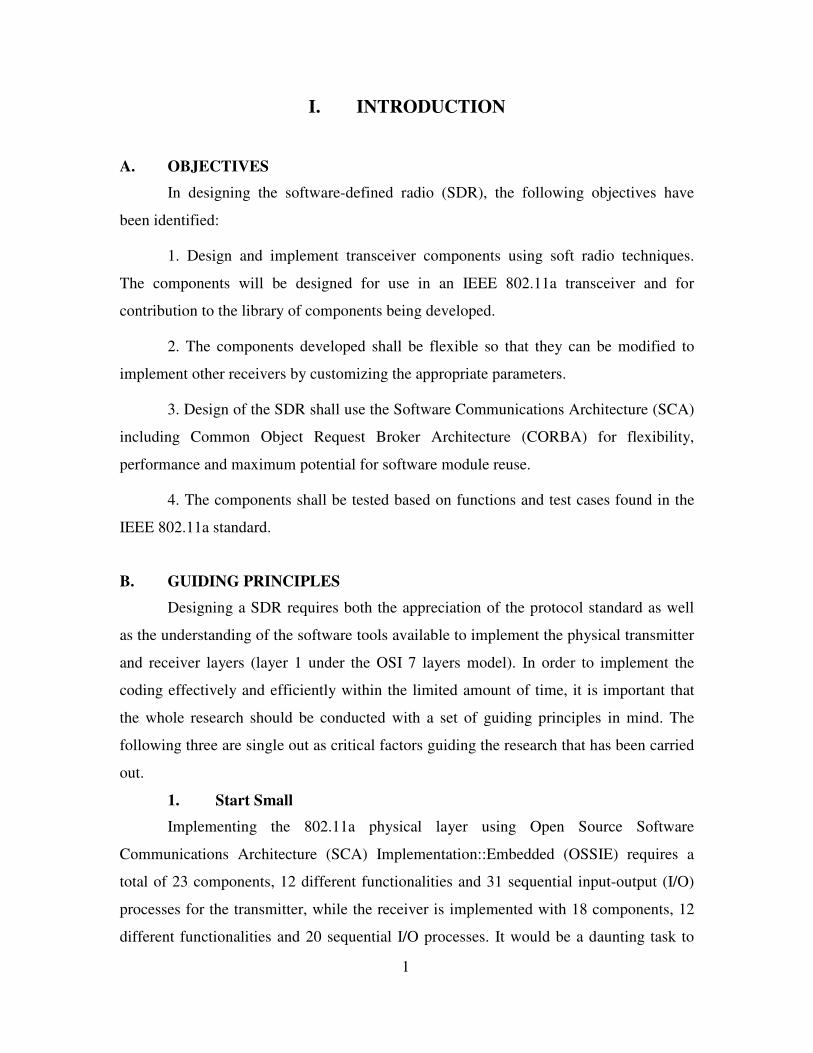
1. Start Small
Implementing the 802.11a physical layer using Open Source Software
Communications Architecture (SCA) Implementation::Embedded (OSSIE) requires a
total of 23 components, 12 different functionalities and 31 sequential input-output (I/O)
processes for the transmitter, while the receiver is implemented with 18 components, 12
different functionalities and 20 sequential I/O processes. It would be a daunting task to
2
jump straight into the coding of a full-scale IEEE 802.11a standard as it is extremely
complex and would probably result in a demoralizing outcome.
Hence, the strategy is to ‘start small’ by first developing simple components that
work. This will help to build up confidence and experience in using the OSSIE software,
which is still a trial version. This assimilation time is needed to understand the
programming language and flow. An Incremental Development Model has been chosen
for the software implementation as it advocates the need to be modular and provides
constant feedback in the design cycle to minimize back tracing. It minimizes major bugs
from occurring in the design further downstream in the implementation. More details on
the model are provided in the next section.
2. Think Modular
As this research is more of a discovery venture (since it is the first time an attempt
has been made to use OSSIE to implement IEEE 802.11a standards), the push for a direct
working design outweighs the need for an efficient one. Hence, it is more important to
get the various components under the standard to carry out their necessary functions,
even though the code may not be written as efficiently as desired. If there is a need,
future efforts can be recommended to optimize the code and integrate it with other
aspects of the standards or hardware. These further enhancements are proposed in the
concluding chapter.
The targets to be modular and reusable reinforce the need to keep the components
‘simple’ so that they can be understood and modified easily for future enhancement.
While the OSSIE waveform developer already provides handy tools to modify
components, it is critical to have good programming discipline in managing the
complexity of the software algorithm. This prevents the code from getting too exclusive
and losing the flexibility of customization.
3. Help is Out There
As mentioned before, OSSIE is still under development and refinement. It is very
important that one is kept up to date regarding the OSSIE software development to fully
3
utilize its capabilities. Through the research, we have been fortunate to have constant
dialogue and guidance from the OSSIE development team at the Virginia Polytechnic
Institute and State University (Virginia Tech).
The algorithm, functions and objects in the software are written in the C++
programming language. However, it is equally important to appreciate the underlying
CORBA interfaces that enable input/output (I/O) interaction between components and
integration of the transmitter and receiver waveforms. Another challenge will be to
understand the IEEE 802.11a communication standard (e.g. modulation, error
corrections, orthogonal frequency division multiplexing) and convert that into the desired
algorithms in the C++ programming language.
To fully understand the various technical details and challenges on one’s own is
nearly impossible in such a short time. It has been important to seek assistance quickly
whenever the implementation reached an obstacle. Proven algorithms and approaches are
referenced so as not to reinvent the wheel. This research is also a collaboration with
Major Low Kian Wai, who was working on the IEEE 802.16 implementation using
OSSIE. Various useful resources include literature studies, Internet research, sample C++
software algorithms, MATLAB simulation for IEEE 802.11a standard, etc. All of these
resources come disjointed but they provide guidance and the tools to complete the thesis
research.
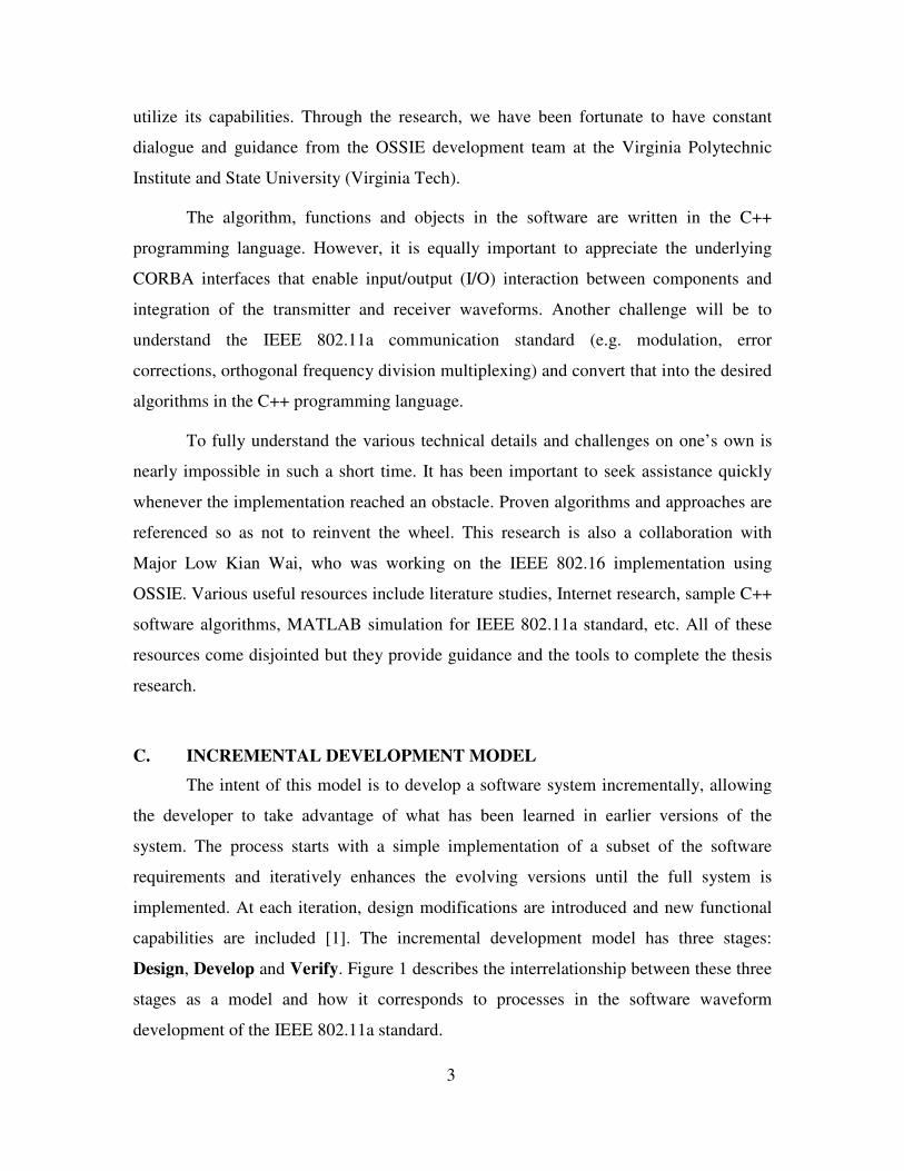
C. INCREMENTAL DEVELOPMENT MODEL
The intent of this model is to develop a software system incrementally, allowing
the developer to take advantage of what has been learned in earlier versions of the
system. The process starts with a simple implementation of a subset of the software
requirements and iteratively enhances the evolving versions until the full system is
implemented. At each iteration, design modifications are introduced and new functional
capabilities are included [1]. The incremental development model has three stages:
Design, Develop and Verify. Figure 1 describes the interrelationship between these three
stages as a model and how it corresponds to processes in the software waveform
development of the IEEE 802.11a standard.
4
Define outline requirement
Assign requirement to
increment
Design system architecture
Develop system increment
Validate increment
Integrate increment
Validate & verify system
Completed system
Model Process
User requirement
Waveform (new / exisitng)
Design & model
s/w designed?
Build waveform(compile / new fn) Reuse
Test waveform Debug
Waveform perform
correctly?
Test waveform on system (s/w,
h/w)Debug
Verify requriement?
No
Yes
No
Yes
No
Yes
Design
Develop
Verify
Figure 1. Incremental Development Model.2
1. Design
This stage starts with defining the outline software requirements and assigning
these requirements to the specific increment. From these requirements, the system
architecture is designed to serve as a framework for actual software development in the
next stage.
2 Eric Christensen, Elisa Wing, “Waveform application development process for software defined radios”, IEEE article, Motorola SSG and SPAWARSYSCEN, 2000: 234
5
2. Develop
This is the actual ‘hands on’ of software development and programming, whereby
the system requirements and pseudo-codes are converted to actual software languages.
The coded algorithms are validated incrementally to ensure they meet the functionality
expectations. Successful increments are stored for future use and new functionalities
through design modifications are introduced for the next increment.
3. Verify
With the incremental development, the software system design gets larger and
more complex. Increments shall be integrated in this stage and verified that the system as
a whole is able to meet the holistic software requirements. For this research, the
completed system must be able to emulate the IEEE 802.11a physical layer for both the
transmitter and the receiver.
D. THESIS CHAPTERS BREAKDOWN
In this thesis, we present the approach of implementing a SDR transceiver using
OSSIE as the software platform. This work has been divided into seven chapters. The
following shows the focus of each chapter:
Chapter I: Introduction. This chapter begins by giving an overview of the thesis
objectives and follow by describing the guiding principles behind the design. The
Incremental Development Model is also discussed to set the framework for subsequent
chapters.
Chapter II: Design. In this chapter, the key concepts stipulated in the thesis title
are conveyed as requirements. Conceptual design using MATLAB models are discussed
before the OSSIE detailed design model is presented. In the detailed design, transmitter
and receiver models are discussed separately.
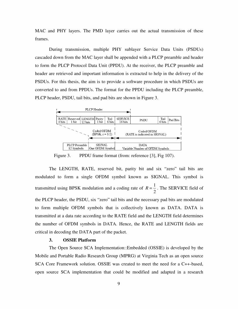
Chapter III: Develop – Transmitter. The design of the transmitter is presented
in this chapter. The discussion is divided into preamble, SIGNAL and DATA subframes.
It ends with the design of concatenating the three subframes to form the PPDU frame.
6
Chapter IV: Develop – Receiver. The design of the receiver is presented in this
chapter. Similar to the transmitter, the chapter is divided into preamble, SIGNAL and
DATA subframes.
Chapter V: Challenges. The IFFT/FFT and Viterbi decoder are singled out as
special interest components as their design are both involved and complex. Difficulties
and peculiarities of OSSIE software are also mentioned.
Chapter VI: Verify. Testing of the final product is carried out with reference to
the IEEE 802.11a standard. The test results for both transmitter and receiver models are
presented in this chapter.
Chapter VII: Conclusion. This chapter gives a review on the thesis objectives
and provides recommendations on potential future work with the baseline components
developed.
7
II. DESIGN
A. REQUIREMENTS ANALYSIS
In order to meet the thesis objectives, it is important to fully understand the
concepts underlying base on the thesis topic – “Software Defined Radio design for an
IEEE 802.11a Transceiver using OSSIE”. The three important concepts are Software
Defined Radio, the IEEE 802.11a wireless standard and OSSIE. In the following section,
these three concepts are presented in sufficient detail to set the design boundaries. This
shall lead to the conceptual design of the eventual software architecture.
1. Software Defined Radio
SDR refers to a radio that can be “substantially defined in software and whose
physical layer behavior can be significantly altered through changes to its software” [2].
SDR has advantages over conventional radio as it promotes multi-functionality, mobility,
compactness, ease of manufacture and ease of upgrades. The design of a SDR generally
comprises a series of procedures that include system engineering, RF chain planning,
Analog-to-Digital and Digital-to-Analog hardware selections, software and hardware
architecture selection and radio validations. For this research, the focus is only on
software architecting according to a specific standard – IEEE 802.11a.
The extent of software architecting or the boundary where software algorithms
shall be written is shown in Figure 2.
Figure 2. Model of Software Defined Radio.
For the transmitter, all functionalities from the input binary data to the digitized
input to the Digital-to-Analog Converter (DAC) will be implemented in software.
Similarly, for the receiver, all functionalities after the Analog-to-Digital Converter
8
(ADC) to the regeneration of the binary received information will be implemented in this
thesis work. It is important to note that all software components are implemented at base
band, i.e., before up-conversion at the transmitter and after down-conversion at the
receiver.
2. IEEE 802.11a PHY Layer
The physical standard takes reference from Part11: IEEE Std 802.11a-1999
(Revision 2003) [3]. It describes the wireless LAN Medium Access Control (MAC) and
Physical Layer (PHY) specifications, specifically for high-speed physical layer in the 5
GHz band. Since the following implementation is done at base band, the carrier
frequency of approximately 5 GHz band is immaterial. IEEE 802.11a is based on
Orthogonal Frequency-Division Multiplexing (OFDM) whereby a single transmission is
encoded into multiple subcarriers. Section 17 of the standard (OFDM PHY specification
for the 5 GHz band) is the working document upon which this thesis’s algorithm is based.
A simplified explanation of the working of the OFDM PHY layer can also be found in
reference [4].
Important design requirements of an IEEE 802.11a PHY system are as follows:
a) data payload communication capabilities of 6, 9, 12, 18, 24, 36, 48, and 54
Mbits/s
b) mandatory transmitting and receiving at data rates of 6, 12, and 24 Mbits/s
c) 52 subcarriers that are modulated using binary or quadrature phase shift
keying (BPSK/QPSK), 16-quadrature amplitude modulation (QAM), or 64-
QAM.
d) Forward error correction coding (convolutional coding) with a coding rate of
1/2, 2/3, or 3/4. Viterbi decoding will be implemented at the receiver.
e) 1 OFDM symbol per 4 µs (250, 000 sym/s)
The IEEE 802.11a PHY layer consists of two core sub-layers: Physical Layer
Convergence Procedure (PLCP) and Physical Medium Dependent (PMD) layer. The
PLCP maps the MAC frames onto the medium and serves as the boundary between the
9
MAC and PHY layers. The PMD layer carries out the actual transmission of these
frames.
During transmission, multiple PHY sublayer Service Data Units (PSDUs)
cascaded down from the MAC layer shall be appended with a PLCP preamble and header
to form the PLCP Protocol Data Unit (PPDU). At the receiver, the PLCP preamble and
header are retrieved and important information is extracted to help in the delivery of the
PSDUs. For this thesis, the aim is to provide a software procedure in which PSDUs are
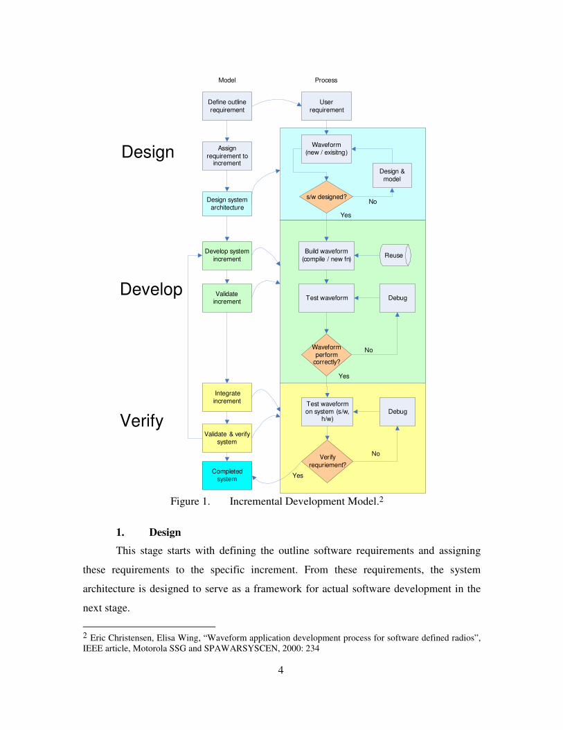
converted to and from PPDUs. The format for the PPDU including the PLCP preamble,
PLCP header, PSDU, tail bits, and pad bits are shown in Figure 3.
Figure 3. PPDU frame format (from: reference [3], Fig 107).
The LENGTH, RATE, reserved bit, parity bit and six “zero” tail bits are
modulated to form a single OFDM symbol known as SIGNAL. This symbol is
transmitted using BPSK modulation and a coding rate of 12
R = . The SERVICE field of
the PLCP header, the PSDU, six “zero” tail bits and the necessary pad bits are modulated
to form multiple OFDM symbols that is collectively known as DATA. DATA is
transmitted at a data rate according to the RATE field and the LENGTH field determines
the number of OFDM symbols in DATA. Hence, the RATE and LENGTH fields are
critical in decoding the DATA part of the packet.
3. OSSIE Platform
The Open Source SCA Implementation::Embedded (OSSIE) is developed by the
Mobile and Portable Radio Research Group (MPRG) at Virginia Tech as an open source
SCA Core Framework solution. OSSIE was created to meet the need for a C++-based,
open source SCA implementation that could be modified and adapted in a research
10
environment. The current version of OSSIE (0.5.0) is based on version 2.2.1 of the SCA
specification. A detailed presentation of the OSSIE platform can be found in Jacob A.
DePriest’s thesis entitled “A Practical Approach to Rapid Prototyping of SCA
Waveforms” at Virginia Tech [5]. From his thesis, the reader would be able to appreciate
the OSSIE Waveform Developer (OWD) environment, specifically the following
knowledge:
a) able to customize and design OSSIE components according to specific port
implementation and inter-components threading strategies
b) able to set up device assignment to each component being developed
c) able to design a waveform using OWD to map a Radio design to the OSSIE
software components available
This thesis is written with the assumption that the reader has certain prior
knowledge about the C++ programming language, including object-oriented design.
There are four important C++ files generated for each new component: <Component
Name>.h, <Component Name>.cpp, port_impl.h and port_impl.cpp. These are where the
functionalities are defined for the component. The content of these generated C++ files
are modified to provide the actual functionality of a radio component.
a) port_impl.h and port_impl.cpp: implement the port communication between
components, determining what is to be received and sent
b) <Component Name>.h and <Component Name>.cpp: ‘brain’ of the
component, where its functionalities are programmed. Most of the post-
generation codes are resided in the process_data() function call within
<Component Name>.cpp.
B. CONCEPTUAL DESIGN
Following the principle of iterative and incremental development, five models
have been developed, with each being more complex and built on the experiences
gathered from the previous. The first three are exploratory models using MATLAB,
which are relatively easy to build since many of the radio functionalities are already
available as function calls. The fourth model builds on the success of the MATLAB
11
design. It emulates a Transmitter-Receiver (Tx-Rx) design using OSSIE but following
closely the previous MATLAB model. The final model is the full scale OSSIE
implementation of IEEE 802.11a PHY layer, which is the primary objective of this thesis
work. A summary of the models is provided in Figure 4. The first four models are
described here to demonstrate the incremental approach, while Section C presents the
Next, a QPSK modulation / demodulation was implemented. The block
diagram and components description are shown in Figure 6 and Table 2, respectively.
The main MATLAB file that calls the various functions is mainQPSK.m.
Figure 6. MATLAB QPSK transceiver model.
Filename Purpose dataGen generate the tx binary data txIQ generate I and Q channel signals for QPSK (serial to parallel) txMF Tx pulse-shaping using root raised cosine filterRRC generate coefficients of Nyquist filter channel model channel distortion (e.g. AWGN, fading) rxMF Rx pulse-shaping using root raised cosine rxSample sample the matched filter outputs rxIQ demodulate I and Q channels signals for QPSK (parallel to serial) thresholdDet threshold detector using Comparator
The final design was an attempt to implement QPSK modulation with
OFDM using MATLAB. The block diagram and component descriptions are shown in
Figure 7 and Table 3, respectively. This design is the closest to the IEEE 802.11a PHY
layer with many familiar functions that would eventually be ‘converted’ to components in
OSSIE. These important functions include modulation mapping, normalization, inverse
fast Fourier transform (IFFT) for OFDM, guard insert (or cyclic prefix insert) for the
transmitter and demodulation mapping, unnormalization, fast Fourier transform (FFT) for
OFDM and guard removal (or cyclic prefix removal) for the receiver. The main
MATLAB file that calls the various functions is mainOFDM.m.
Figure 7. MATLAB OFDM transceiver model.
Filename Purpose OFDMdataGen generate initial serial binary data SerToPara serial to parallel conversion QpskMod perform QPSK modulation Normalize Normalize the tx data IFFT IFFT for the Tx data GiINS insert guard interval into transmission signal GiRem remove guard interval from received signal FFT FFT for the Rx data UnNormalize UnNormalize the rx data QpskDemod perform QPSK demodulation ParaToSer parallel to serial conversion ThresDet0 threshold detector using Comparator
A summary of the functionalities of each component is provided in Table 5. The
index abides by the following naming convention:
a) The first digit from the left represents the frame or subframe that the
component belongs to. An exception is the preamble training sequences
whereby Tx1.1.x represents component that forms the short training sequence
and Tx1.2.x represents component that forms the long training sequence.
First digit Frame / subframe
0 PSDU
1 preamble subframe
2 SIGNAL subframe
3 DATA subframe
12 PPDU
b) The last digit from the left represents the function of the component.
Last digit Function
0 PSDU formation
1 preamble subframe formation
2 SIGNAL subframe formation
3 DATA subframe formation
4 Scrambler
5 Tail-replacement
6 Convolution encoder
7 Interleaver
8 Modulation
9 Carriers mapper
10 IFFT
11 Cyclic prefix
12 PPDU formation
For illustrations, Tx2.7 indicates a component under the SIGNAL subframe (2)
that carries out the interleaving (7) function.
19
Index Component Functions Preamble subframe Tx1 preamble_map - initiate the Tx routine
- form short training (ST) and long training (LT) sequence - send preamble (ST + LT) to PPDU
Tx1.1 short training (ST) Tx1.1.9 ST_carrier_map - ST carrier mapping Tx1.1.10 ST_IFFT - ST IFFT Tx1.2 long training (LT) Tx1.2.9 LT_carrier_map - LT carrier mapping Tx1.2.10 LT_IFFT - LT IFFT Tx1.2.11 LT_cyclicPrefix - LT cyclic prefix append SIGNAL subframe Tx2 header_map
(SIGNAL_map) - form SIGNAL (SIG) samples - send SIG to PPDU
Tx2.6 SIG_conv_enc - SIG convolution encoding Tx2.7 SIG_interleaver - SIG interleaving Tx2.8 SIG_BPSK_mod - SIG BPSK modulation Tx2.9 SIG_carriers_map - SIG carriers mapping Tx2.10 SIG_IFFT - SIG IFFT Tx2.11 SIG_cyclicprefix - SIG cyclic prefix DATA subframe Tx3 data_map - form time data samples from PSDU
- send DATA samples to PPDU Tx3.4 data_scrambler - scrambler the raw data Tx3.5 data_tail_replacement - replace tail with zeroes Tx3.6 data_conv_enc - data convolution encoding
- data puncturing Tx3.7 data_interleaver - data interleaving Tx3.8 data_mod_map - data modulation mapping Tx3.9 data_carriers_map - data carriers mapping Tx3.10 data_IFFT - data IFFT Tx3.11 data_cyclicprefix - data cyclic prefix Tx12 PPDU_map - form PPDU frame from Preamble, SIG and DATA
subframes for transmission Tx0 data_PSDU - input PSDU data
The functionalities of each component are provided in Table 6. Similar to the
transmitter, the receiver’s component index abides by the following naming convention:
a) The first digit from the left represents the frame or subframe that the
component belongs to.
First digit Frame / subframe
0 Received digitized samples
1 preamble subframe
2 SIGNAL subframe
3 DATA subframe
12 PPDU
b) The last digit from the left represents the function of the component.
Last digit Function
0 Digitized samples retrieval
1 preamble subframe retrieval
2 SIGNAL subframe retrieval
3 DATA subframe retrieval
4 Descrambler
5 Tail-replacement
6 Convolution decoder
7 Deinterleaver
8 Demodulation
9 Carriers demapper
10 FFT
11 Cyclic prefix removal
12 PPDU retrieval
For example, Rx3.7 indicates a component under the DATA subframe (3) that
carries out the deinterleaving (7) function.
24
Index Component Functions Preamble subframe Rx0 Rx_data - received digitized data stream Rx1 / Rx12 PPDU_rx - extract the required digitized PPDU stream
- removed preamble from PPDU - send stream for header removal
SIGNAL subframe Rx2 Header_rx
(SIGNAL_rx) - removed header from PPDU - send header for processing - extract RATE & LENGTH from SIG - send received data for processing
Rx2.11 SIG_cyclicprefix_rem - SIG cyclic prefix removal Rx2.10 SIG_FFT - SIG FFT Rx2.9 SIG_carriers_demap - SIG carriers demapping Rx2.8 SIG_BPSK_demod - SIG BPSK demodulation Rx2.7 SIG_deinterleaver - SIG deinterleaving Rx2.6 SIG_conv_dec - SIG convolution decoding DATA subframe Rx3 data_rx - receive and send raw data for processing
- receive and send PSDU data to MAC layer Rx3.11 data_cyclicprefix_rem - data cyclic prefix removal Rx3.10 data_FFT - data FFT Rx3.9 data_carriers_demap - data carriers demapping Rx3.8 data_demod_map - data demodulation mapping Rx3.7 data_deinterleaver - data deinterleaving Rx3.6 data_conv_dec - data dummy insertion
- data convolution decoding Rx3.5 data_tail_replace - not required, encompass in descrambler Rx3.4 data_descrambler - descrambler the raw data
Figure 23. SIG_interleaver port and functional flow.
4. Tx2.8: BPSK Modulation (SIG)
Component name: SIG_BPSK_mod
Port design: SIG_BPSK_mod has 1 input port and 1 output port. Figure 29 shows
the I/O distribution of the component.
Functional design: The SIGNAL OFDM subcarriers shall be modulated by using
BPSK modulation. The encoded and interleaved binary input data shall be converted into
complex BPSK constellation points. The output values for a modulator are formed by
multiplying the resulting I and Q channel values by a normalization factor KMOD to
achieve the same average power for all mappings. For BPSK modulation, KMOD is unity,
and normalization is not necessary in this specific modulator.
Figure 24. SIG_BPSK_mod port and functional flow.
5. Tx2.9: Carriers Mapping (SIG)
Component name: SIG_carriers_map
Port design: SIG_carriers_map has 1 input port and 1 output port. Figure 25
shows the I/O distribution of the component.
Process data ()
Tx2.6: SIG_conv_enc 1st permutation Tx2.7-O1:
interleaver_outputTx2.8:
SIG_BPSK_modTx2.7-I1:
Interleaver_input
2nd permutation
Tx2.7: SIG_interelaver
35
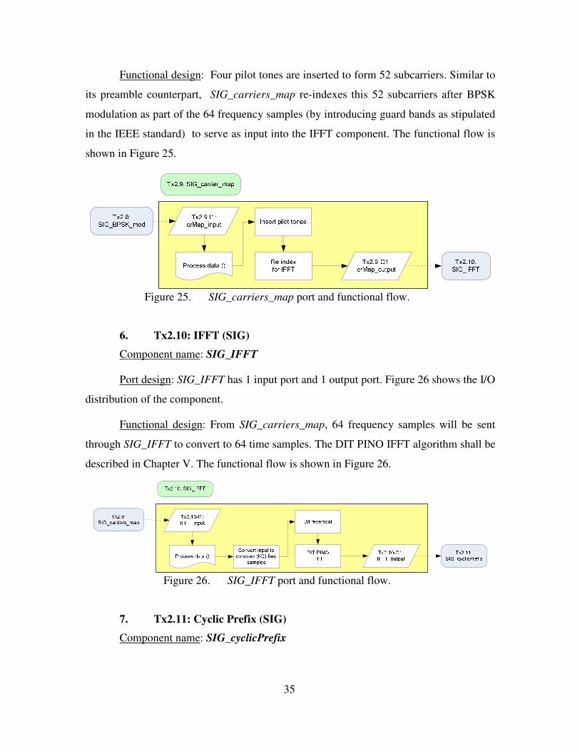
Functional design: Four pilot tones are inserted to form 52 subcarriers. Similar to
its preamble counterpart, SIG_carriers_map re-indexes this 52 subcarriers after BPSK
modulation as part of the 64 frequency samples (by introducing guard bands as stipulated
in the IEEE standard) to serve as input into the IFFT component. The functional flow is
shown in Figure 25.
Figure 25. SIG_carriers_map port and functional flow.
6. Tx2.10: IFFT (SIG)
Component name: SIG_IFFT
Port design: SIG_IFFT has 1 input port and 1 output port. Figure 26 shows the I/O
distribution of the component.
Functional design: From SIG_carriers_map, 64 frequency samples will be sent
through SIG_IFFT to convert to 64 time samples. The DIT PINO IFFT algorithm shall be
described in Chapter V. The functional flow is shown in Figure 26.
Figure 26. SIG_IFFT port and functional flow.
7. Tx2.11: Cyclic Prefix (SIG)
Component name: SIG_cyclicPrefix
36
Port design: SIG_cyclicPrefix has 1 input port and 1 output port. Figure 27 shows
the I/O distribution of the component.
Functional design: SIG_cyclicPrefix prefixes a quarter of the length of the IFFT
time samples to the data to form the SIGNAL subframe. This sequence shall be
forwarded to SIGNAL_map to be concatenated as part of PPDU. The functional flow is
shown in Figure 27.
Figure 27. SIG_cyclicPrefix port and functional flow.
C. DATA
The DATA field contains the SERVICE field, the PSDU, the TAIL bits, and the
PAD bits (when necessary). The SERVICE field has 16 bits as shown in Figure 28. The
first 7 bits are set to zeros to synchronize the descrambler over at the receiver. The
remaining 9 bits are reserved for future use and are also set to zero. The PSDU tail bit
field shall be six bits of “0”, which serve the function of returning the convolutional
encoder to the “zero state” (similar function as the 6 tail bits of SIGNAL field). The
PPDU tail bit field shall be maintained by replacing six scrambled “zero” bits following
the end of the message (which may not be “zero”) with six non-scrambled “zero” bits.
Figure 28. Composition of SERVICE field (from: reference [3], Fig. 112).
37
Besides all the components (functionalities) under the SIGNAL subframe,
forming the DATA subframe requires an additional initial procedure of scrambling the
information. Table 10 summarizes the components needed to form the DATA subframe.
Index Component Functions Tx3 data_map - form time data samples from PSDU
- send DATA samples to form PPDU Tx3.4 data_scrambler - scramble the raw data Tx3.5 data_tail_replacement - replace tail with zero Tx3.6 data_conv_enc - data convolutional encoding
- data puncturing Tx3.7 data_interleaver - data interleaving Tx3.8 data_mod_map - data modulation mapping Tx3.9 data_carriers_map - data carriers mapping Tx3.10 data_IFFT - data IFFT Tx3.11 data_cyclicprefix - data cyclic prefix Tx0 data_PSDU - input PSDU data Table 10. IEEE 802.11a Transmitter DATA subframe components functionalities.
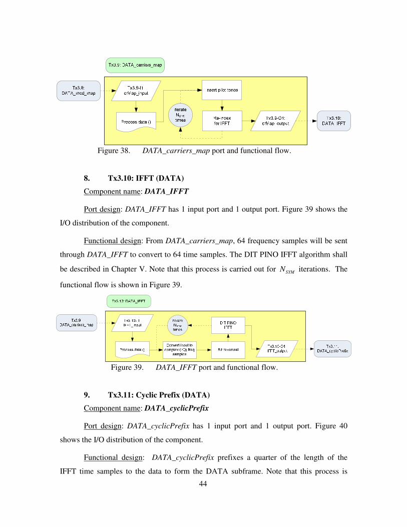
1. Tx3: DATA Mapping
Component name: DATA_map
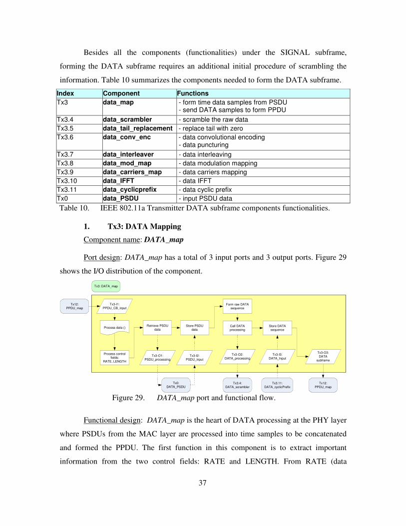
Port design: DATA_map has a total of 3 input ports and 3 output ports. Figure 29
shows the I/O distribution of the component.
Figure 29. DATA_map port and functional flow.
Functional design: DATA_map is the heart of DATA processing at the PHY layer
where PSDUs from the MAC layer are processed into time samples to be concatenated
and formed the PPDU. The first function in this component is to extract important
information from the two control fields: RATE and LENGTH. From RATE (data
Tx3-O1: PSDU_processing
Tx12: PPDU_map
Store PSDU data
Call DATA processing
Tx3.4: DATA_scrambler
Tx3.11: DATA_cyclicPrefix
Store DATA sequence
Tx3-O2: DATA_processing
Tx3-O3: DATA
subframe
Tx3-I3: DATA_Input
Tx12: PPDU_map
Tx3: DATA_map
Process data ()
Tx0:DATA_PSDU
Tx3-I1: PPDU_CB_input
Tx3-I2: PSDU_input
Process control fields:
RATE, LENGTH
Retrieve PSDU data
Form raw DATA sequence
38
transmission rate), the modulation type and coding parameters are defined as shown in
Port design: SIG_cyclicPrefix_rem has a total of 1 input port and 1 output port.
Figure 45 shows the I/O distribution of the component.
Functional design: SIG_cyclicPrefix_rem removes the prefixes (a quarter of the
length of the IFFT time samples) from the input data to retrieve the original time samples
obtained from the transmitter IFFT. This sequence shall be forwarded to SIG_FFT for the
FFT. The functional flow is shown in Figure 45.
Figure 45. SIG_cyclicPrefix_rem port and functional flow.
Rx1: PPDU_rx
Extract SIGNAL subframe
Call SIG processing
Rx2.6: SIG_conv_dec
Rx2.11: SIG_cyclicPrefix_rem
Store RATE & LENGTH
Rx2-O1: SIG_process_output
Rx2-O2: SIG_rx_output
Rx2-I2: SIG_process_input
Rx3: DATA_rx
Rx2: SIGNAL_rx
Process data ()
Rx2-I1: SIG_rx_input
Process data ()
Rx2.11-I1: cyPre_rem_input
Rx2.11-O1: cyPre_rem_output
Remove the cyclic prefix
Mark end of cyclic prefix
Rx2.10: SIG_FFT
Rx2: SIGNAL_rx
Rx2.11: SIG_cyclicPrefix_rem
51
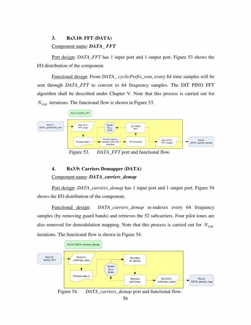
3. Rx2.10: FFT (SIG)
Component name: SIG_FFT
Port design: SIG_FFT has 1 input port and 1 output port. Figure 46 shows the I/O
distribution of the component.
Functional design: From SIG_cyclicPrefix_rem, 64 time samples will be sent
through SIG_FFT to convert to 64 frequency samples. The DIT PINO FFT algorithm
shall be described in Chapter V. The functional flow is shown in Figure 46.
Figure 46. SIG_FFT port and functional flow.
4. Rx2.9: Carriers Demapper (SIG)
Component name: SIG_carriers_demap
Port design: SIG_carriers_demap has 1 input port and 1 output port. Figure 47
shows the I/O distribution of the component.
Functional design: SIG_carriers_demap re-indexes the 64 frequency samples (by
removing guard bands as stipulated in the IEEE standard) and retrieves the 52
subcarriers. Four pilot tones are removed before passing the data stream for BPSK
demodulation. The functional flow is shown in Figure 47.
Figure 47. SIG_carriers_demap port and functional flow.
Rx2.11: SIG_cyclicPrefix_rem
Rx2.10: SIG_FFT
Process data ()
Rx2.10-I1: FFT_input
Rx2.10-O1: FFT_output
Convert input to complex (I/Q) freq
samples
Bit reverssal
DIT PINO FFT
Rx2.9: SIG_carriers_demap
Rx2.9: SIG_carriers_demap
Process data ()
Rx2.9-I1: crDemap_input
Rx2.9-O1: crDemap_output
Re-index for BPSK demod
Rx2.10: SIG_FFT
Remove pilot tones
Rx2.8: SIG_BPSK_demod
52
5. Rx2.8: BPSK Demodulator (SIG)
Component name: SIG_BPSK_demod
Port design: SIG_BPSK demod has 1 input port and 1 output port. Figure 48
shows the I/O distribution of the component.
Functional design: The SIGNAL bits are retrieved by using BPSK demodulation.
The 48 frequency subcarriers are demodulated to retrieve the encoded and interleaved
binary data, taking into consideration the normalization factor, MODK (see Table 12). For
BPSK demodulation, MODK is unity. The functional flow is shown in Figure 48.
Figure 48. SIG_BPSK demod port and functional flow.
6. Rx2.7: De-Interleaver (SIG)
Component name: SIG_deinterleaver
Port design: SIG_deinterleaver has 1 input port and 1 output port. Figure 49
shows the I/O distribution of the component.
Functional design: All data bits are passed through a block deinterleaver after
demodulation. The deinterleaver has a block size equals to the number of coded bits in a
single OFDM symbol, CBPSN (see Table 15). The deinterleaver consists of two different
permutations, which is the inverse of the transmitter interleaver described in Chapter III.
Note that j , i and k refer to the index of the coded bit before the first, before the second
and after the second permutation, respectively. Note that max ,12BPSCN
s � �= � �� �
. Equation 6
and 7 respectively describe the first and second permutations.
(16 ) mod , , 0,1, , -1CBPSCBPS
j ji s floor j floor s i j k N
s N� �� �= × + + × =� �� �
� � � �� (6)
Process data ()
BPSK demodmapping
Rx2.8-O1: demod_output
Rx2.7: SIG_deinterleaver
Rx2.8-I1: demod_input
Rx2.9: SIG_carriers_demap
Rx2.8: SIG_BPSK_demod
Normalize KMOD
53
16 - ( - 1) (16 )CBPSCBPS
ik i N floor
N= × × (7)
Figure 49. SIG_deinterleaver port and functional flow.
7. Rx2.6: Convolutional Decoder (SIG)
Component name: SIG_conv_dec
Port design: SIG_conv_dec has 1 input port and 1 output port. Figure 50 shows
the I/O distribution of the component.
Functional design: Viterbi decoding is chosen to decode the stream of
convolutional bits. Since the SIGNAL fields have been coded with a convolutional
encoder of coding rate 12
R = , there is no need to insert dummy bits prior decoding.
Details of the Viterbi decoder algorithm are presented in Chapter V. The functional flow
is shown in Figure 50.
Figure 50. SIG_conv_dec port and functional flow.
Process data ()
Rx2.8: SIG_BPSK_demod 1st permutation Rx2.7-O1:
deinterleaver_outputRx2.7-I1:
deInterleaver_input
2nd permutation
Rx2.7: SIG_deinterelaver
Rx2.6: SIG_conv_dec
Process data ()
Rx2.6: SIG_conv_dec
Recover punctured data Viterbi decoding
initialise_viterbi()
process_viterbi()
Coding rate?
Rx2.6-O1: convdec_output
R=2/3
Rx2.7:SIG_deinterleaver
Insert dummy ‘zero’ appropriatelyR=1/2
R=3/4
Rx2.6-I1: convdec_input
Rx2: SIGNAL_rx
54
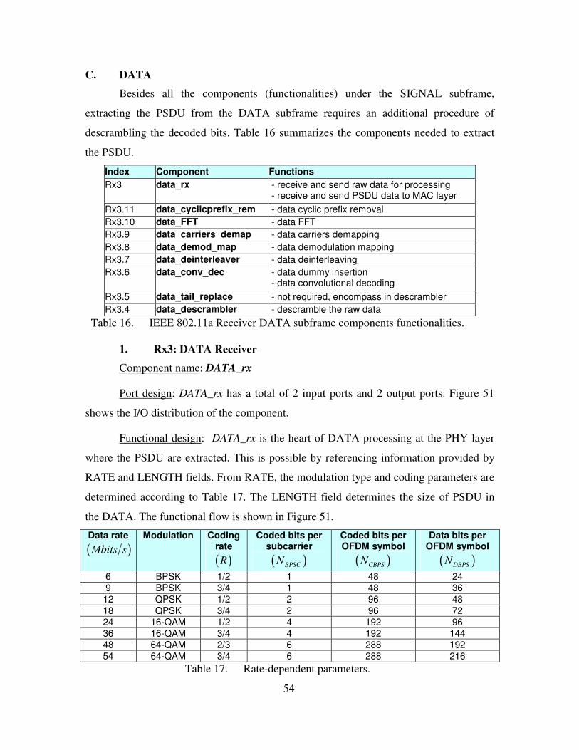
C. DATA
Besides all the components (functionalities) under the SIGNAL subframe,
extracting the PSDU from the DATA subframe requires an additional procedure of
descrambling the decoded bits. Table 16 summarizes the components needed to extract
the PSDU.
Index Component Functions Rx3 data_rx - receive and send raw data for processing
- receive and send PSDU data to MAC layer Rx3.11 data_cyclicprefix_rem - data cyclic prefix removal Rx3.10 data_FFT - data FFT Rx3.9 data_carriers_demap - data carriers demapping Rx3.8 data_demod_map - data demodulation mapping Rx3.7 data_deinterleaver - data deinterleaving Rx3.6 data_conv_dec - data dummy insertion
- data convolutional decoding Rx3.5 data_tail_replace - not required, encompass in descrambler Rx3.4 data_descrambler - descramble the raw data
Table 16. IEEE 802.11a Receiver DATA subframe components functionalities.
1. Rx3: DATA Receiver
Component name: DATA_rx
Port design: DATA_rx has a total of 2 input ports and 2 output ports. Figure 51
shows the I/O distribution of the component.
Functional design: DATA_rx is the heart of DATA processing at the PHY layer
where the PSDU are extracted. This is possible by referencing information provided by
RATE and LENGTH fields. From RATE, the modulation type and coding parameters are
determined according to Table 17. The LENGTH field determines the size of PSDU in
the DATA. The functional flow is shown in Figure 51.
Table 28. SIG_conv_enc detail traces and explanations.
75
c. Tx2.7: Interleaver (SIG)
This component carries out the function of interleaving the encoded
SIGNAL field. The detailed traces are captured in sig_interleaver.txt and a summary of
the traces are provided in Table 29. The traces show that 48 binary bits are received and
interleaved to form 48 binary bits.
No Trace Explanations 1 Real short pushpacket received, length 48 48 SIGNAL encoded bits received 2 Processing SIG interleaver, size: 48 48 bits went through two permutations of
interleaving Table 29. SIG_interleaver detail traces and explanations.
d. Tx2.8: BPSK Modulation (SIG)
This component carries out the function of BPSK modulation on the
interleaved bits. The detailed traces are captured in sig_bpsk_mod.txt and a summary of
the traces are provided in Table 30. The traces show that 48 binary bits are received and
modulated to a size of 48 complex BPSK samples.
No Trace Explanations 1 Real short pushpacket received, length 48 48 SIGNAL interleaved bits received 2 Processing BPSK modulation
SIG modulated data, Length 48 Modulated into 48 BPSK I/Q float samples
Table 30. SIG_BPSK_mod detail traces and explanations.
e. Tx2.9: Carriers Mapping (SIG)
This component carries out the function of carriers mapping on the
SIGNAL field. The detailed traces are captured in sig_carriers_map.txt and a summary
of the traces are provided in Table 31. The traces show that 48 complex samples are
received and carriers-mapped to a size of 64 complex samples for IFFT.
No Trace Explanations 1 Complex float pushpacket received, length 48 48 I/Q float samples received
2 Processing carrier mapping SIG carriers mapped data, Length 64
Mapped into 64 samples for IFFT
Table 31. SIG_carriers_map detail traces and explanations.
f. Tx2.10: IFFT (SIG)
This component carries out the function of IFFT on the SIGNAL field.
The detailed traces are captured in sig_ifft.txt and a summary of the traces are provided in
76
Table 32. The traces show that 64 complex samples are received and gone through IFFT
to form 64 complex samples.
No Trace Explanations 1 Complex float pushpacket received, length 64 64 I/Q float samples received
2 Processing SIG IFFT SIG_IFFT Tx data, Length 64
Mapped into 64 time samples after IFFT
Table 32. SIG_IFFT detail traces and explanations.
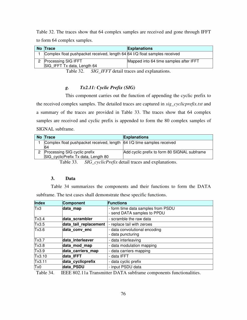
g. Tx2.11: Cyclic Prefix (SIG)
This component carries out the function of appending the cyclic prefix to
the received complex samples. The detailed traces are captured in sig_cyclicprefix.txt and
a summary of the traces are provided in Table 33. The traces show that 64 complex
samples are received and cyclic prefix is appended to form the 80 complex samples of
SIGNAL subframe.
No Trace Explanations 1 Complex float pushpacket received, length
64 64 I/Q time samples received
2 Processing SIG cyclic prefix SIG_cyclicPrefix Tx data, Length 80
Add cyclic prefix to form 80 SIGNAL subframe
Table 33. SIG_cyclicPrefix detail traces and explanations.
3. Data
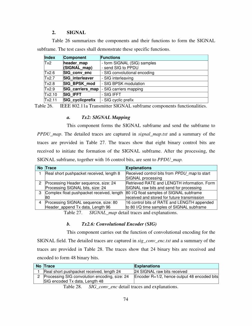
Table 34 summarizes the components and their functions to form the DATA
subframe. The test cases shall demonstrate these specific functions.
Index Component Functions Tx3 data_map - form time data samples from PSDU
- send DATA samples to PPDU Tx3.4 data_scrambler - scramble the raw data Tx3.5 data_tail_replacement - replace tail with zeroes Tx3.6 data_conv_enc - data convolutional encoding
- data puncturing Tx3.7 data_interleaver - data interleaving Tx3.8 data_mod_map - data modulation mapping Tx3.9 data_carriers_map - data carriers mapping Tx3.10 data_IFFT - data IFFT Tx3.11 data_cyclicprefix - data cyclic prefix Tx0 data_PSDU - input PSDU data Table 34. IEEE 802.11a Transmitter DATA subframe components functionalities.
77
a. Tx3: DATA Mapping
This component forms the DATA subframe and send the subframe to
PPDU_map. The detailed traces are captured in data_map.txt and a summary of the
traces are provided in Table 35. The traces show that 24 binary control bits are received
to initiate the formation of the DATA subframe. After retrieving the PSDU information
bits, the binary bits are sent for processing to form the DATA subframe. The final step
involves sending the 480 complex samples of DATA subframe to PPDU_map.
No Trace Explanations 1 Real short pushpacket received, length 24 Received control bits from PPDU_map to start
DATA processing (include RATE and LENGTH) 2 Activate PSDU processing
Data Tx Bits, Length 24 Activate transfer of PSDU to DATA_map
3 Real short pushpacket received, length 800 800 PSDU raw bits (100 octets) received 4 Send raw data for scrambling
Data Tx Bits, Length 869 864 DATA bits send for processing (PAD bits added), 5 control bits (CBs) appended
5 Complex float pushpacket received, length 480
480 I/Q DATA time samples received
6 Send processed data to form PPDU Data_append Tx data, Length 480
Send DATA time samples to PPDU_map
Table 35. DATA_map detail traces and explanations.
b. Tx3.4: Scrambler (DATA)
This component carries out the function of scrambling the DATA field.
The detailed traces are captured in data_scrambler.txt and a summary of the traces are
provided in Table 36. The traces show that 864 binary bits are received and formed 864
scrambled bits. Note that there are five control bits being passed between components.
No Trace Explanations 1 Real short pushpacket received, length 869 864 (and 5 CBs) raw bits received 2 Processing data in the scrambler
Scrambled data Bits, Length 869 864 scrambled bits sent out together with 5 CBs
Table 36. DATA_scrambler detail traces and explanations.
c. Tx3.5: Tail Replacement (DATA)
This component carries out the function of replacing the scrambled tail
bits in the DATA field with non-scrambled “zero” bits. The detailed traces are captured
in data_tail_replace.txt and a summary of the traces are provided in Table 37. The traces
show that 864 scrambled bits are received and formed 864 bits after the tail bits are
replaced. Note that there are five control bits being passed between components.
78
No Trace Explanations 1 Real short pushpacket received, length 869 864 (and 5 CBs) scrambled bits received 2 Processing tail replacement
Tail replaced data Bits, Length 869 864 sent out together with 5 CBs after tail replacement
Table 37. DATA_tail_replacement detail traces and explanations.
d. Tx3.6: Convolutional Encoder (DATA)
This component carries out the function of convolutional encoding for the
DATA field. The detailed traces are captured in data_conv_enc.txt and a summary of the
traces are provided in Table 38. The traces show that 864 binary bits are received and
encoded with a coding rate of 34
(with puncturing) to form 1152 binary bits. Note that
there are five control bits being passed between components.
No Trace Explanations 1 Real short pushpacket received, length 869 864 bits received 2 Processing Data convolution encoding, size: 864
Puncturing the encoded Data, size: 1152 Data encoded Tx data, Length 1157
36 Mbits/s : coding rate of 3/4, hence 1152 output bits from 864 input bits. 5 CBs added to the transmitted data
Table 38. DATA_conv_enc detail traces and explanations.
e. Tx3.7: Interleaver (DATA)
This component carries out the function of interleaving the encoded
DATA field. The detailed traces are captured in data_interleaver.txt and a summary of
the traces are provided in Table 39. The traces show that 1152 binary bits are received
and interleaved to form 1152 binary bits. Note that there are five control bits being passed
between components.
No Trace Explanations 1 Real short pushpacket received, length 1157 1152 DATA encoded bits received 2 Processing Data interleaver, size: 1152
Data interleaved Tx bits, Length 1157 1152 bits went through two permutations of interleaving
Table 39. DATA_interleaver detail traces and explanations.
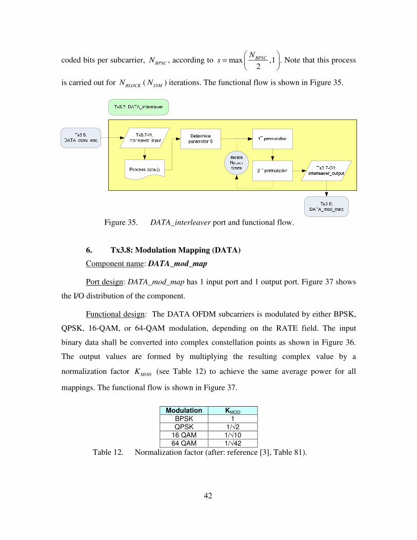
f. Tx3.8: Modulation Mapping (DATA)
This component carries out the function of 16-QAM modulation on the
interleaved bits. The detailed traces are captured in data_mod_map.txt and a summary of
the traces are provided in Table 40. The traces show that 1152 binary bits are received
79
and modulated to a size of 288 complex 16-QAM samples. Note that there are five
control bits being passed between components.
No Trace Explanations 1 Real short pushpacket received, length 1157 1152 DATA interleaved bits received 2 Processing 16QAM modulation
Data modulated samples, Length 293 36 Mbits/s : 16-QAM modulation, hence modulated into 288 16-QAM I/Q float samples with 5 CBs
Table 40. DATA_mod_map detail traces and explanations.
g. Tx3.9: Carriers Mapping (DATA)
This component carries out the function of carriers mapping on the DATA
field. The detailed traces are captured in data_carriers_map.txt and a summary of the
traces are provided in Table 41. The traces show that 288 complex samples are received
and carriers-mapped to a size of 384 complex samples for IFFT. Note that there is only
one control bit being passed between components.
No Trace Explanations 1 Complex float pushpacket received, length
293 288 I/Q float samples received
2 Processing carrier mapping Data carriers mapped data, Length 385
Mapped into 6 x 64 samples for IFFT with 1 CB.
Table 41. DATA_carriers_map detail traces and explanations.
h. Tx3.10: IFFT (DATA)
This component carries out the function of IFFT on the DATA field. The
detailed traces are captured in data_ifft.txt and a summary of the traces are provided in
Table 42. The traces show that 384 complex samples are received and gone through IFFT
to form 384 complex samples. Note that there is only one control bit being passed
between components.
No Trace Explanations 1 Complex float pushpacket received, length
385 6 x 64 I/Q float samples received
2 Processing DATA IFFT DATA_IFFT Tx data, Length 385
Mapped into 64 time samples after IFFT (6 iterations), with 1 CB
Table 42. DATA_IFFT detail traces and explanations.
80
i. Tx3.11: Cyclic Prefix (DATA)
This component carries out the function of appending the cyclic prefix to
the received complex samples. The detailed traces are captured in data_cyclicprefix.txt
and a summary of the traces are provided in Table 43. The traces show that 384 complex
samples are received and cyclic prefix is appended to form the 480 complex samples of
DATA subframe.
No Trace Explanations 1 Complex float pushpacket received, length
385 6 x 64 I/Q time samples received
2 Processing Data cyclic prefix Data_cyclicPrefix Tx data, Length 480
Add cyclic prefix (6 x 16 samples) to form 480 DATA subframe
Table 43. DATA_cyclicPrefix detail traces and explanations.
4. PPDU (Final Concatenation)
The final piece to the transmitter is the function of concatenating the preamble,
SIGNAL and DATA subframes together and form the PPDU frame. This main control is
carried out by PPDU_map component.
a. Tx12: PPDU Mapping
This component forms the PPDU frame from the three subframes. The
detailed traces are captured in PPDU_map.txt and a summary of the traces are provided
in Table 44. The traces show that binary control bits are sent to initiate the formation of
SIGNAL and DATA subframes. The traces also show the retrieval of the preamble,
SIGNAL and DATA subframes. The final PPDU frame consists of 880 complex samples.
No Trace Explanations 1 Complex float pushpacket received, length
320 480 I/Q Preamble time samples received
2 Sent Header control bits CB Tx data, Length 8
Activate SIGNAL subframe processing
3 Complex float pushpacket received, length 96
80 I/Q SIGNAL time samples received, with 16 CBs (RATE and LENGTH)
4 Sent DATA control bits CB Tx data, Length 24
Activate DATA subframe processing
5 Complex float pushpacket received, length 480
480 I/Q DATA time samples received
6 Processing PPDU sequence, size: 880 Final PPDU frame of 880 I/Q time samples to be sent out for transmission
Table 44. PPDU_map detail traces and explanations
81
B. RECEIVER
In this section, functionalities of the receiver components shall be verified. As
annex G in the standard only described the transmitter outputs, receiver components are
tested on their abilities to regenerate the transmitter input data (e.g. the receiver decoder
outputs should be similar to the transmitter encoder input). Similar to the previous
section, this section is broken down into preamble, SIGNAL and DATA subframes, and
the test results are divided into two categories: summarized and detailed traces. The
summarized trace is attached in APPENDIX C. The entire receiver test passes through 20
I/O sequential flows, and this is summarized in APPENDIX D. The detailed traces in this
section are described according to (1) the functions of the component, (2) files where the
test results are traced and stored, and (3) evaluation of the test results. All the files
mentioned in this chapter have been included in the reference CD.
1. Preamble
Table 45 summarizes the components and their functions to remove the preamble
subframe. The test cases shall demonstrate these specific functions.
Index Component Functions Rx0 Rx_data - received digitized data stream Rx1 / Rx12 PPDU_rx - extract the required digitized PPDU stream
- removed preamble from PPDU - send stream for header removal
Table 50. SIG_cyclicPrefix_rem detail traces and explanations.
c. Rx2.10: FFT (SIG)
This component carries out the function of FFT on the SIGNAL subframe.
The detailed traces are captured in sig_fft.txt and a summary of the traces are provided in
Table 51. The traces show that 64 complex samples are received and gone through FFT
to form 64 complex samples.
No Trace Explanations 1 Complex float pushpacket received, length
64 64 I/Q float samples received
2 Processing SIG FFT SIG_FFT Tx data, Length 64
Mapped into 64 complex subcarriers after FFT
Table 51. SIG_FFT detail traces and explanations.
d. Rx2.9: Carriers Demapper (SIG)
This component carries out the function of carriers demapping on the
SIGNAL subframe. The detailed traces are captured in sig_carriers_demap.txt and a
84
summary of the traces are provided in Table 52. The traces show that 64 complex
samples are received and carriers-demapped to a size of 48 complex samples.
No Trace Explanations 1 Complex float pushpacket received, length
64 64 I/Q subcarriers received
2 Processing carrier demapping SIG carriers demapped data, Length 48
Mapped into 48 complex constellations for BPSK demodulation
Table 52. SIG_carriers_demap detail traces and explanations.
e. Rx2.8: BPSK Demodulator (SIG)
This component carries out the function of BPSK demodulation on the
complex samples. The detailed traces are captured in sig_bpsk_demod.txt and a summary
of the traces are provided in Table 53. The traces show that 48 complex samples are
received and demodulated to a size of 48 binary bits.
No Trace Explanations 1 Complex float pushpacket received, length 48 48 BPSK I/Q float samples received 2 Processing SIG BPSK demodulation
SIG demodulated data, Length 48 Demodulated into 48 serial bits
Table 53. SIG_BPSK_demod detail traces and explanations.
f. Rx2.7: De-Interleaver (SIG)
This component carries out the function of deinterleaving the demodulated
SIGNAL field. The detailed traces are captured in sig_deinterleaver.txt and a summary of
the traces are provided in Table 54. The traces show that 48 binary bits are received and
deinterleaved to form 48 binary bits.
No Trace Explanations 1 Real short pushpacket received, length 48 48 SIGNAL demodulated bits received 2 Processing SIG deinterleaver, size: 48
SIG deinterleaved Tx data, Length 48 48 bits went through two permutations of deinterleaving
Table 54. SIG_deinterleaver detail traces and explanations.
g. Rx2.6: Convolutional Decoder (SIG)
This component carries out the function of convolutional decoding on the
SIGNAL field. The detailed traces are captured in sig_conv_dec.txt and a summary of the
traces are provided in Table 55. The traces show that 48 binary bits are received and
decoded to form 24 binary bits.
85
No Trace Explanations 1 Real short pushpacket received, length 48 48 SIGNAL bits received for decoding 2 Processing SIG convolution decoding, size: 48
return from initialise viterbi return from process viterbi SIG decoded Tx data, Length 24
Show bits went through initialize_viterbi() and process_viterbi(). 24 bits produced at end of decoding.
Table 55. SIG_conv_dec detail traces and explanations.
3. Data
Table 56 summarizes the components and their functions to retrieve PSDU from
the DATA subframe. The test cases shall demonstrate these specific functions.
Index Component Functions Rx3 data_rx - receive and send raw data for processing
- receive and send PSDU data to MAC layer Rx3.11 data_cyclicprefix_rem - data cyclic prefix removal Rx3.10 data_FFT - data FFT Rx3.9 data_carriers_demap - data carriers demapping Rx3.8 data_demod_map - data demodulation mapping Rx3.7 data_deinterleaver - data deinterleaving Rx3.6 data_conv_dec - data dummy insertion
- data convolutional decoding Rx3.5 data_tail_replace - not required, encompass in descrambler Rx3.4 data_descrambler - descramble the raw data
Table 56. IEEE 802.11a Receiver DATA subframe components functionalities.
a. Rx3: DATA Receiver
This component carries out the functions of sending the DATA subframe
for processing and retrieving the PSDU information bits. The detailed traces are captured
in data_rx.txt and a summary of the traces are provided in Table 57. The traces show that
480 complex samples are sent for processing and 864 binary bits belonging to DATA
field are received. The 800 PSDU information bits are sent out together with a control bit.
No Trace Explanations 1 Complex float pushpacket received, length
485 480 I/Q samples (DATA subframes) received, with 5 CBs
2 Sent raw data for processing ... Data output, Length 485
480 I/Q samples of DATA subframe sent for processing, with 5 CBs
3 Real short pushpacket received, length 864 864 DATA bits received (including PAD bits) 4 Send PSDU data to MAC layer ...
PSDU Data output, Length 801 800 PSDU bits sent out, including 1 bit of LENGTH field
Table 57. DATA_rx detail traces and explanations.
86
b. Rx3.11: Cyclic Prefix Removal (DATA)
This component carries out the function of removing the cyclic prefix
from the DATA subframe. The detailed traces are captured in data_cyclicprefix_rem.txt
and a summary of the traces are provided in Table 58. The traces show that 480 complex
samples are received and cyclic prefix is removed to form the 384 complex samples.
Note that there are five control bits being passed between components.
No Trace Explanations 1 Complex float pushpacket received, length
485 480 I/Q DATA time samples received, with 5 CBs
B. RECEIVER ************************************ Welcome to OSSIE simulation: 802.11a PPDU receiver ************************************ Start PPDU digitised receiver stream_sizeI = 884, stream_sizeQ = 884 Removed preamble from PPDU samples Preamble match at pointer: 4 Sent PPDU (preamble removed) samples PPDU_preamble_removed data, Length 560 ************************************ Start PPDU Header remove function ************************************ Complex float pushpacket received, length 560 Sent SIG time samples for processing ... Header removed data output, Length 80 ************************************ Start SIG_cyclicPrefix_rem function ************************************ Complex float pushpacket received, length 80 Processing SIG cyclic prefix remove SIG_cyclicPrefix_rem Tx data, Length 64 ************************************ Start SIG_FFT function ************************************ Complex float pushpacket received, length 64 Processing SIG FFT FFT frequency output (Magnitude), Length 64 SIG_FFT Tx data, Length 64 ************************************ Start SIG_carriers_demap function ************************************ Complex float pushpacket received, length 64 Processing carrier demapping SIG carriers demapped data, Length 48 ************************************ Start SIG_demodulation function ************************************ Complex float pushpacket received, length 48 Processing SIG BPSK demodulation SIG demodulated data, Length 48 ************************************ Start SIG_deinterleaver function ************************************ Real short pushpacket received, length 48 Processing SIG deinterleaver, size: 48 SIG deinterleaved Tx data, Length 48 ************************************ Start SIG convolution decoding function ************************************ Real short pushpacket received, length 48 Processing SIG convolution decoding, size: 48 We are inside initialise_viterbi Nstate = 64; Nsr = 6 return from initialise viterbi We are inside process_viterbi No. of iterations: 24 return from process viterbi End of decoding SIG decoded Tx data, Length 24 ************************************ SIG header information received ************************************ Real short pushpacket received, length 24 Processing Data sequence, rate: 36 Mbit/s, length: 100 octets Send raw data for decoding Header removed data output, Length 485 ************************************ Start Data recovery function ************************************
106
Complex float pushpacket received, length 485 Sent raw data for processing ... Data output, Length 485 ************************************ Start Data_cyclicPrefix_rem function ************************************ Complex float pushpacket received, length 485 Processing Data cyclic prefix remove Data_cyclicPrefix_rem Tx data, Length 389 ************************************ Start Data_FFT function ************************************ Complex float pushpacket received, length 389 Processing Data FFT FFT frequency output (Magnitude), Length 384 Data_FFT Tx data, Length 389 ************************************ Start Data_carriers_demap function ************************************ Complex float pushpacket received, length 389 Processing data carrier demapping Data carriers demapped data, Length 293 ************************************ Start Data_demodulation function ************************************ Complex float pushpacket received, length 293 Processing Data demodulation Conduct 16QAM demodulation Data demodulated data, Length 1157 ************************************ Start Data_deinterleaver function ************************************ Real short pushpacket received, length 1157 Processing Data deinterleaver Data deinterleaved Tx data, Length 1157 ************************************ Start Data convolution decoding function ************************************ Real short pushpacket received, length 1157 Processing Data convolution decoding Recover the punctured encoded Data, size: 1152 We are inside initialise_viterbi Nstate = 64; Nsr = 6 return from initialise viterbi We are inside process_viterbi No. of iterations: 144 We are inside process_viterbi No. of iterations: 144 We are inside process_viterbi No. of iterations: 144 We are inside process_viterbi No. of iterations: 144 We are inside process_viterbi No. of iterations: 144 We are inside process_viterbi No. of iterations: 144 return from process viterbi End of decoding Data decoded Tx data, Length 869 ************************************ Start Data_descrambler function ************************************ Real short pushpacket received, length 869 Processing data in the descrambler Descrambled data Bits, Length 864 ************************************ Decoded Data received ************************************ Real short pushpacket received, length 864 Send PSDU data to MAC layer ... PSDU Data output, Length 801
107
************************************ Start Data_PSDU display function ************************************ Real short pushpacket received, length 801 Start PSDU display ... Received data successfully decoded: Received octet data [0]: 04 Received octet data [1]: 02 Received octet data [2]: 00 Received octet data [3]: 2e Received octet data [4]: 00 Received octet data [5]: 60 Received octet data [6]: 08 Received octet data [7]: cd Received octet data [8]: 37 Received octet data [9]: a6 Received octet data [10]: 00 Received octet data [11]: 20 Received octet data [12]: d6 Received octet data [13]: 01 Received octet data [14]: 3c Received octet data [15]: f1 Received octet data [16]: ef Received octet data [17]: 7a Received octet data [18]: 51 Received octet data [19]: 92 Received octet data [20]: 3b Received octet data [21]: af Received octet data [22]: 00 Received octet data [23]: 00 Received octet data [24]: 4a Received octet data [25]: 6f Received octet data [26]: 79 Received octet data [27]: 2c Received octet data [28]: 20 Received octet data [29]: 62 Received octet data [30]: 72 Received octet data [31]: 69 Received octet data [32]: 67 Received octet data [33]: 68 Received octet data [34]: a3 Received octet data [35]: 2f Received octet data [36]: 73 Received octet data [37]: 70 Received octet data [38]: 61 Received octet data [39]: 72 Received octet data [40]: 6b Received octet data [41]: 20 Received octet data [42]: 6f Received octet data [43]: 66 Received octet data [44]: 20 Received octet data [45]: 64 Received octet data [46]: 69 Received octet data [47]: 76 Received octet data [48]: 69 Received octet data [49]: 6e Received octet data [50]: 69 Received octet data [51]: 74 Received octet data [52]: 83 Received octet data [53]: 2d Received octet data [54]: 0a Received octet data [55]: 44 Received octet data [56]: 61 Received octet data [57]: 75 Received octet data [58]: 67 Received octet data [59]: 68 Received octet data [60]: 74 Received octet data [61]: 65 Received octet data [62]: 72 Received octet data [63]: 20 Received octet data [64]: 6f
108
Received octet data [65]: 66 Received octet data [66]: 20 Received octet data [67]: 45 Received octet data [68]: 6c Received octet data [69]: 79 Received octet data [70]: 72 Received octet data [71]: 69 Received octet data [72]: 75 Received octet data [73]: 6d Received octet data [74]: 2c Received octet data [75]: 0a Received octet data [76]: 46 Received octet data [77]: 69 Received octet data [78]: 72 Received octet data [79]: 65 Received octet data [80]: 2d Received octet data [81]: 69 Received octet data [82]: 6e Received octet data [83]: 73 Received octet data [84]: 69 Received octet data [85]: 72 Received octet data [86]: 65 Received octet data [87]: 64 Received octet data [88]: 20 Received octet data [89]: 77 Received octet data [90]: 65 Received octet data [91]: 20 Received octet data [92]: 74 Received octet data [93]: 72 Received octet data [94]: 65 Received octet data [95]: 61 Received octet data [96]: da Received octet data [97]: 57 Received octet data [98]: 99 Received octet data [99]: ed ************************************ Phew! It finally works ... ... ************************************ End of OSSIE simulation: 802.11a PPDU receiver ************************************
109
APPENDIX D: IEEE 802.11A TEST SEQUENTIAL FLOW CHART
A. TRANSMITTER
IEEE 802.11a Transmitter components sequential flow Example (802.11a Annex G) Components Description Data In Type In Data Out Type Out Data size in Data size out
1 preamble_map - initiate the tx routine - start ST sequence processing - - complex integer - 52
9 PPDU_map - receive preamble - send CB to start SIG processing complex float real integer 320 8
10 header_map - receive RATE & LENGTH - send raw SIG for processing real integer real integer 8 24
11 SIG_conv_enc - SIG convolution encoding real integer real integer 24 48 12 SIG_interleaver - SIG interleaving real integer real integer 48 48 13 SIG_BPSK_mod - SIG BPSK modulation real integer complex float 48 48 14 SIG_carriers_map - SIG carriers mapping complex float complex float 48 64 15 SIG_IFFT - SIG IFFT complex float complex float 64 64 16 SIG_cyclicprefix - SIG cyclic prefix complex float complex float 64 80
110
IEEE 802.11a Transmitter components sequential flow Example (802.11a Annex G) Components Description Data In Type In Data Out Type Out Data size in Data size out
17 header_map - receive SIG samples - send SIG to PPDU complex float complex float 80 96
18 PPDU_map - receive SIG samples - send CB to start data processing complex float real integer 96 24
19 data_map
- receive RATE & LENGTH - send CB to start PSDU processing real integer real integer 24 24
20 data_PSDU - input PSDU data real integer real integer 24 800
21 data_map
- receive PSDU data - send CB to start PSDU processing real integer real integer 800 869
22 data_scrambler - scrambler the raw data real integer real integer 869 869 23 data_tail_replacement - replace tail with zeroes real integer real integer 869 869
24 data_conv_enc - data convolution encoding - data puncturing real integer real integer 869 1157
25 data_interleaver - data interleaving real integer real integer 1157 1157 26 data_mod_map - data modulation mapping real integer complex float 1157 293 27 data_carriers_map - data carriers mapping complex float complex float 293 385
30 data_map - receive time data samples - send time data samples to PPDU complex float complex float 480 480
31 PPDU_map
- receive time data samples - form PPDU packet for transmission complex float complex float 480 880
111
B. RECEIVER
IEEE 802.11a Receiver components sequential flow Example (802.11a Annex G) Components Description Data In Type In Data Out Type Out Data size in Data size out
1 Rx_data - received digitised data stream - - complex float - continuous
2 PPDU_rx
- extract the required digitised PPDU stream - removed preamble from PPDU - send stream for header removal complex float complex float continuous 560
3 Header_rx - removed header from PPDU - send header for processing complex float complex float 560 80
4 SIG_cyclicprefix_rem - SIG cyclic prefix removal complex float complex float 80 64 5 SIG_FFT - SIG FFT complex float complex float 64 64 6 SIG_carriers_demap - SIG carriers demapping complex float complex float 64 48 7 SIG_BPSK_demod - SIG BPSK demodulation complex float real integer 48 48 8 SIG_deinterleaver - SIG deinterleaving real integer real integer 48 48 9 SIG_conv_dec - SIG convolution decoding real integer real integer 48 24
10 Header_rx
- extract RATE & LENGTH from SIG - send received data for processing real integer complex float 24 485
11 data_rx - receive and send raw data for processing complex float complex float 485 485