NAVAL POSTGRADUATE SCHOOL MONTEREY, CALIFORNIA THESIS Approved for public release; distribution is unlimited SECURITY ENHANCEMENT OF LITTORAL COMBAT SHIP CLASS UTILIZING AN AUTONOMOUS MUSTERING AND PIER MONITORING SYSTEM by Philip Stubblefield March 2010 Thesis Advisors: Rachel Goshorn Deborah Goshorn Second Reader: Mark Stevens
Transcript
NAVAL
POSTGRADUATE SCHOOL
MONTEREY, CALIFORNIA
THESIS
Approved for public release; distribution is unlimited
SECURITY ENHANCEMENT OF LITTORAL COMBAT SHIP CLASS UTILIZING AN AUTONOMOUS
MUSTERING AND PIER MONITORING SYSTEM
by
Philip Stubblefield
March 2010
Thesis Advisors: Rachel Goshorn Deborah Goshorn Second Reader: Mark Stevens
i
REPORT DOCUMENTATION PAGE Form Approved OMB No. 0704-0188 Public reporting burden for this collection of information is estimated to average 1 hour per response, including the time for reviewing instruction, searching existing data sources, gathering and maintaining the data needed, and completing and reviewing the collection of information. Send comments regarding this burden estimate or any other aspect of this collection of information, including suggestions for reducing this burden, to Washington headquarters Services, Directorate for Information Operations and Reports, 1215 Jefferson Davis Highway, Suite 1204, Arlington, VA 22202-4302, and to the Office of Management and Budget, Paperwork Reduction Project (0704-0188) Washington DC 20503. 1. AGENCY USE ONLY (Leave blank)
2. REPORT DATE March 2010
3. REPORT TYPE AND DATES COVERED Master’s Thesis
4. TITLE AND SUBTITLE Security Enhancement of Littoral Combat Ship Class Utilizing an Autonomous Mustering and Pier Monitoring System 6. AUTHOR(S) Stubblefield, Philip N
5. FUNDING NUMBERS
7. PERFORMING ORGANIZATION NAME(S) AND ADDRESS(ES) Naval Postgraduate School Monterey, CA 93943-5000
8. PERFORMING ORGANIZATION REPORT NUMBER
9. SPONSORING /MONITORING AGENCY NAME(S) AND ADDRESS(ES) N/A
10. SPONSORING/MONITORING AGENCY REPORT NUMBER
11. SUPPLEMENTARY NOTES The views expressed in this thesis are those of the author and do not reflect the official policy or position of the Department of Defense or the U.S. Government. . IRB Protocol number ________________. 12a. DISTRIBUTION / AVAILABILITY STATEMENT Approved for public release; distribution is unlimited
12b. DISTRIBUTION CODE
13. ABSTRACT (maximum 200 words) Littoral Combat Ships (LCS) are designed and built to have minimum crew sizes thus, while the ship is in port, there are fewer crewmembers to facilitate pier monitoring, security, and conducting mustering of personnel. The crew of LCS ships presently have too many responsibilities to ensure 100% coverage of the Pier area 100% of the time, and cannot manually maintain a real time muster of all ships personnel. This lack of coverage and situational awareness could make LCS ships vulnerable to terrorist attacks or terrorist monitoring.
This thesis addresses the capability gap for complete and automated personnel mustering and situational awareness in the pier area for LCS class ships. Through applying the Systems Engineering process, the concept, external systems diagram, requirements, and functional architectures for a generic solution are proposed. The proposed solution is an autonomous system utilizing facial recognition software to maintain a muster of the ship’s crew, while in parallel monitoring the pier area, looking for any known person of interest (e.g., terrorists) and providing appropriate alerts.
Additionally, this thesis provides a demonstrable proof-of-concept prototype system solution, named Pier Watchman. Its instantiated physical architecture of a specific autonomous solution to pier monitoring and personnel mustering is provided.
15. NUMBER OF PAGES
115
14. SUBJECT TERMS Systems Engineering, Facial Recognition, Force Protection, Pier Security, Mustering
16. PRICE CODE
17. SECURITY CLASSIFICATION OF REPORT
Unclassified
18. SECURITY CLASSIFICATION OF THIS PAGE
Unclassified
19. SECURITY CLASSIFICATION OF ABSTRACT
Unclassified
20. LIMITATION OF ABSTRACT
UU NSN 7540-01-280-5500 Standard Form 298 (Rev. 2-89) Prescribed by ANSI Std. 239-18
ii
THIS PAGE INTENTIONALLY LEFT BLANK
iii
Approved for public release; distribution is unlimited
SECURITY ENHANCEMENT OF LITTORAL COMBAT SHIP CLASS UTILIZING AN AUTONOMOUS MUSTERING AND PIER MONITORING
SYSTEM
Philip N. Stubblefield Lieutenant, United States Navy
B.S., Jacksonville University, 2003
Submitted in partial fulfillment of the requirements for the degree of
MASTER OF SCIENCE IN SYSTEMS ENGINEERING
from the
NAVAL POSTGRADUATE SCHOOL March 2010
Author: Philip Stubblefield
Approved by: Rachel Goshorn Co-Advisor
Deborah Goshorn Co-Advisor
Mark Stevens Second Reader
Clifford Whitcomb Chairman, Department of Systems Engineering
iv
THIS PAGE INTENTIONALLY LEFT BLANK
v
ABSTRACT
Littoral Combat Ships (LCS) are designed and built to have minimum crew sizes
thus, while the ship is in port, there are fewer crewmembers to facilitate pier monitoring,
security, and conducting mustering of personnel. The crew of LCS ships presently have
too many responsibilities to ensure 100% coverage of the Pier area 100% of the time, and
cannot manually maintain a real time muster of all ships personnel. This lack of coverage
and situational awareness could make LCS ships vulnerable to terrorist attacks or terrorist
monitoring.
This thesis addresses the capability gap for complete and automated personnel
mustering and situational awareness in the pier area for LCS class ships. Through
applying the Systems Engineering process, the concept, external systems diagram,
requirements, and functional architectures for a generic solution are proposed. The
proposed solution is an autonomous system utilizing facial recognition software to
maintain a muster of the ship’s crew, while in parallel monitoring the pier area, looking
for any known person of interest (e.g., terrorists) and providing appropriate alerts.
Additionally, this thesis provides a demonstrable proof-of-concept prototype
system solution, named Pier Watchman. Its instantiated physical architecture of a
specific autonomous solution to pier monitoring and personnel mustering is provided.
vi
THIS PAGE INTENTIONALLY LEFT BLANK
vii
TABLE OF CONTENTS
I. INTRODUCTION........................................................................................................1 A. PROBLEM STATEMENT .............................................................................1
1. Personal Motivation/Experience.........................................................2 B. SHIP CLASS GENERAL INFORMATION.................................................3 C. THE CURRENT MUSTERING PROCESS .................................................4 D. THE CURRENT FORCE PROTECTION PROCESS................................5 E. SYSTEMS ENGINEERING OVERVIEW ...................................................5 F. THESIS OUTLINE..........................................................................................7
1. Chapter II: Application of Systems Engineering Process ...............7 2. Chapter III: Design Reference Mission .............................................7 3. Chapter IV: Generic System Architecture ........................................7 4. Chapter V: Proposed System Solution...............................................8 5. Chapter VI: Summary and Conclusions............................................8
II. APPLICATION OF SYSTEMS ENGINEERING PROCESS................................9 A. SYSTEMS ENGINEERING PROCESS........................................................9 B. SYSTEMS ENGINEERING V-MODEL.......................................................9 C. PROBLEM DEFINITION AND SYSTEM CONCEPT ............................10 D. SYSTEM LEVEL DESIGN REQUIREMENTS AND
ARCHITECTURE.........................................................................................11 1. Analysis of Alternatives.....................................................................11
E. ITEM LEVEL DESIGN REQUIREMENTS ..............................................11 F. FABRICATE, INTEGRATE, AND TEST ..................................................12
III. DESIGN REFERENCE MISSION (DRM).............................................................15 A. DESIGN REFERENCE MISSION ..............................................................15
1. Problem Definition.............................................................................15 2. Operational Need ...............................................................................16 3. Operational Situation (OPSIT) Generation ....................................16 4. Projected Operating Environment...................................................16
a. Geography ...............................................................................17 b. Weather....................................................................................17
IV. GENERIC SYSTEM ARCHITECTURE................................................................27 A. OPERATIONAL VIEW (OV)......................................................................27
viii
B. EXTERNAL SYSTEMS DIAGRAM (ESD) ...............................................28 C. REQUIREMENTS.........................................................................................29 D. GENERIC SYSTEM FUNCTIONAL ARCHITECTURE........................31
V. PROPOSED SYSTEM SOLUTION ........................................................................41 A. ANALYSIS OF ALTERNATIVES ..............................................................41 B. PROPOSED SYSTEM CONCEPT..............................................................42 C. THE PROPOSED MUSTERING AND FORCE PROTECTION
PROCESSES ..................................................................................................43 D. FACE RECOGNITION THEORY..............................................................45 E. PROPOSED SOLUTION FUNCTIONS .....................................................48 F. PROPOSED SYSTEM FUNCTIONAL ARCHITECTURE.....................49 G. REQUIREMENTS.........................................................................................57 H. APPLICATION OF THE SYSTEMS ENGINEERING PROCESS TO
THE PIER WATCHMAN PROOF-OF-CONCEPT SYSTEM ................59 I. PURPOSE FOR PROOF-OF-CONCEPT SYSTEM .................................60 J. PROOF-OF-CONCEPT SYSTEM DESIGN AND
IMPLEMENTATION ...................................................................................60 K. INSTANTIATED PHYSICAL ARCHITECTURE AND NETWORK
CONSTRUCTION.........................................................................................61 L. SOFTWARE UTILIZED ..............................................................................63 M. PIER WATCHMAN PROGRAM DESIGN LANGUAGE (PDL)............63 N. PIER WATCHMAN SOURCE CODE........................................................64 O. SYSTEM OPERATION................................................................................64 P. PROOF-OF-CONCEPT SYSTEM OPERATION AND TESTING.........68 Q. LESSONS LEARNED WHILE DESIGNING, BUILDING, AND
TESTING THE PIER WATCHMAN PROOF-OF-CONCEPT SYSTEM .........................................................................................................70
R. CONCLUSIONS DRAWN FROM PROOF-OF-CONCEPT SYSTEM ..71
VI. SUMMARY AND CONCLUSIONS ........................................................................73 A. SUMMARY ....................................................................................................73 B. CONCLUSION ..............................................................................................73 C. AREAS OF FURTHER RESEARCH..........................................................74
LIST OF REFERENCES......................................................................................................77
APPENDIX A PIER WATCHMAN PROOF-OF-CONCEPT PDL ......................81
APPENDIX B PIER WATCHMAN PROOF-OF-CONCEPT CODE ..................83
APPENDIX C HOW TO DEMONSTRATE THE PIER WATCHMAN PROOF-OF-CONCEPT SYSTEM ..........................................................................89
INITIAL DISTRIBUTION LIST .........................................................................................93
ix
LIST OF FIGURES
Figure 1. Generic Database Diagram ............................................................................ xvi Figure 2. Picture of USS Freedom, LCS-1, Underway from Marinette Wisconsin
(From Scott, 2008) .............................................................................................4 Figure 3. Systems Engineering V-Model (From Department of Defense, 2001, 65) .....10 Figure 4. Map of Operating Area (From Google Maps, 2009) .......................................17 Figure 5. Average Temperatures (From city–data.com for Marinette, WI)....................18 Figure 6. Precipitation (From city–data.com for Marinette, WI)....................................18 Figure 7. Humidity (From city–data.com for Marinette, WI) .........................................18 Figure 8. Wind Speed (From city–data.com for Marinette, WI).....................................19 Figure 9. Snowfall (From city–data.com for Marinette, WI)..........................................19 Figure 10. Sunshine (From city–data.com for Marinette, WI)..........................................19 Figure 11. Cloudy Days (From city–data.com for Marinette, WI) ...................................20 Figure 12. System Operational View ................................................................................28 Figure 13. External Systems Diagram...............................................................................29 Figure 14. Generic Functional Architecture Hierarchy.....................................................32 Figure 15. Top-level Function for the Generic System.....................................................33 Figure 16. First-level Decomposition of the System Function Provide Pier
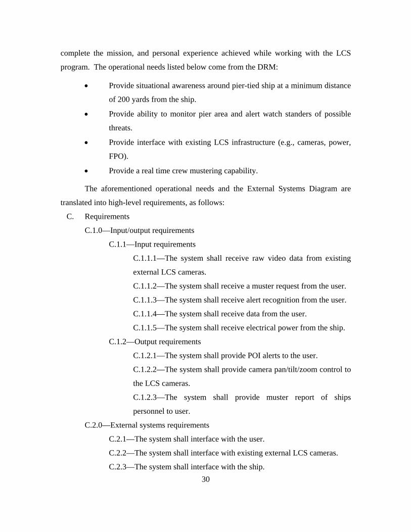
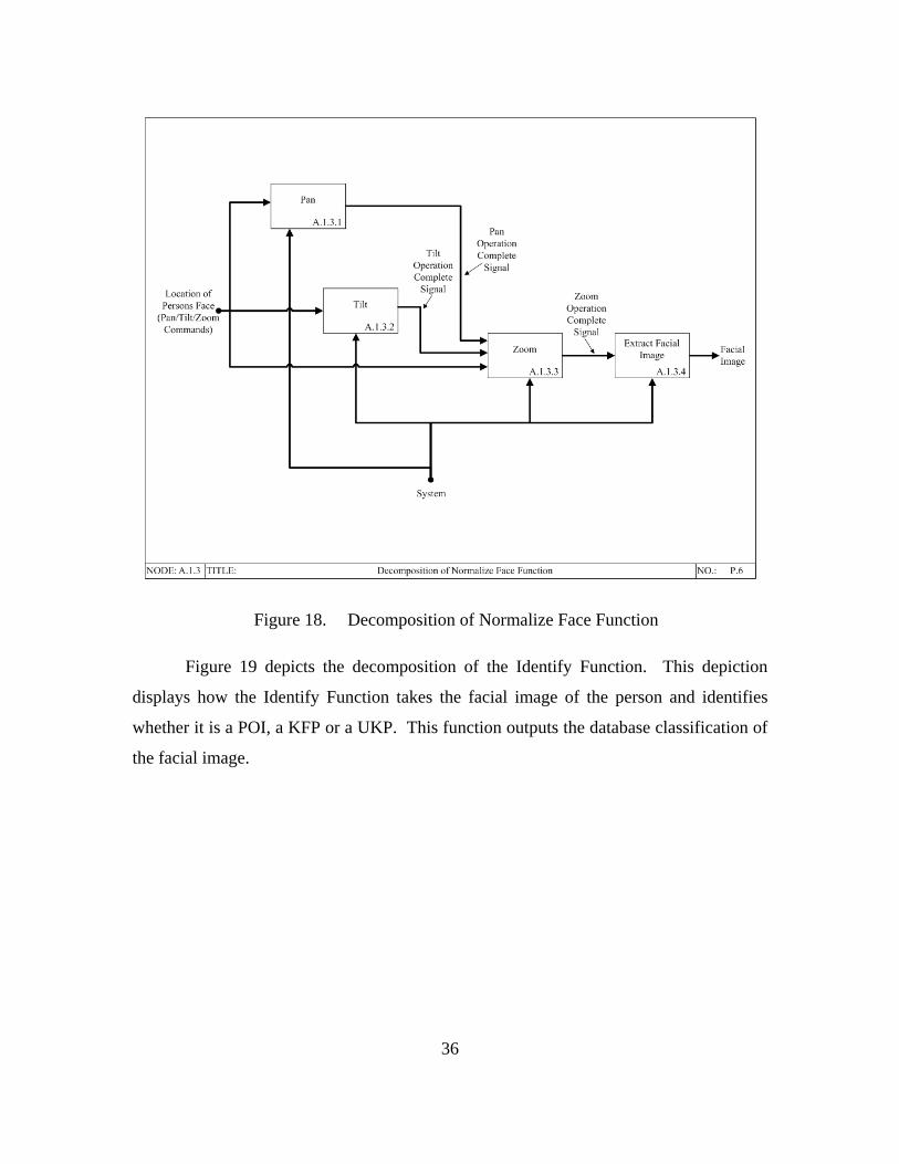
Monitoring and Mustering Services.................................................................34 Figure 17. Decomposition of Detect Function ..................................................................35 Figure 18. Decomposition of Normalize Face Function ...................................................36 Figure 19. Decomposition of Identify Function................................................................37 Figure 20. Decomposition of Provide Database Update Function....................................38 Figure 21. Decomposition of Alert Function ....................................................................39 Figure 22. Decomposition of Log in Database Function ..................................................40 Figure 23. Typical Face (From Turk and Pentland, 1991, 75)..........................................46 Figure 24. Seven of the Eigenfaces Calculated from Typical Face in Figure 23 (From
Turk and Pentland, 1991, 75)...........................................................................47 Figure 25. UMD and MIT Eigenfaces Procedure (From Pentland and Tanzeem, 2000,
53) ....................................................................................................................48 Figure 26. Proposed Proof-of-Concept Functional Architecture Diagram .......................49 Figure 27. Functional Architecture Hierarchy for the Proposed System ..........................49 Figure 28. First-level Decomposition of the System Function for the Proposed
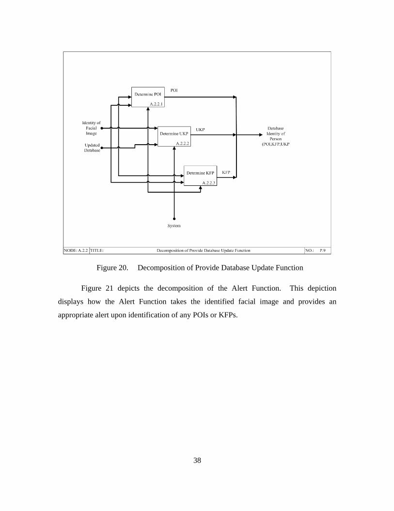
System..............................................................................................................50 Figure 29. Decomposition of Detect Function for the Proposed System..........................51 Figure 30. Decomposition of Normalize Face Function for the Proposed System...........51 Figure 31. Decomposition of Identify Function for the Proposed System........................52 Figure 32. Decomposition of Provide Database Update Function for the Proposed
System..............................................................................................................53 Figure 33. Decomposition of Alert Function for the Proposed System ............................54 Figure 34. Decomposition of Log in Database Function for the Proposed System ..........55 Figure 35. Decomposition of Detect Face Function for the Proposed System .................56 Figure 36. Decomposition of Recognize Face Function for the Proposed System...........57
x
Figure 37. Instantiated Physical Architecture of Pier Watchman Proof-of-Concept System..............................................................................................................62
Figure 38. Snapshot #1: Initial Field of View of the Proof-of-Concept System...............65 Figure 39. Snapshot #2: Image of a Person in the Field of View of the Proof-of-
Concept System ...............................................................................................65 Figure 40. Snapshot #3: P/T/Z Preparation of the Proof-of-Concept System...................66 Figure 41. Snapshot #4: Facial Image Captured ...............................................................66 Figure 42. Facial Images from Known Database ..............................................................67 Figure 43. Correlation of the Facial Image to the Image from the Database ....................68
xi
LIST OF TABLES
Table 1. Threat Characterization Table..........................................................................21 Table 2. List of Metrics (From UJTL, 2003) .................................................................22 Table 3. Sea Shield from Naval Power 21 (From ASN RDA,CHENG, 2007) .............23 Table 4. Joint Capability Areas (From ASN RDA,CHENG, 2007) ..............................24 Table 5. FORCEnet Mission Capabilities (From ASN RDA,CHENG, 2007) ..............24 Table 6. LCS/ Pier Watchman Camera Specification Table (Pelco, 2009) (Sony,
2009) ................................................................................................................61 Table 7. Software Utilized in the Fabrication of Pier Watchman Proof-of-Concept
System..............................................................................................................63 Table 8. The Pier Watchman Proof-of-Concept Acceptance Test Results ....................69
xii
THIS PAGE INTENTIONALLY LEFT BLANK
xiii
LIST OF ACRONYMS AND ABBREVIATIONS
AOA Analysis of Alternatives
CAT5 Category Five
COAL Common Operational Activities List
COTS Commercial Off-the-Shelf
DOD Department of Defense
DRM Design Reference Mission
ESD External Systems Diagram
FOV Field of View
FTP File Transfer Protocol
IDEF0 Integrated Definition for Function Modeling
IEEE Institute of Electrical and Electronics Engineers
JCA Joint Capability Area
KFP Known Friendly Person
LAN Local Area Network
LCS Littoral Combat Ship
MIT Massachusetts Institute of Technology
NCSE Net-Centric Systems Engineering
NTA Naval Tasks
NTTL Navy Tactical Task List
OOD Officer of the Deck
OPSIT Operational Situation
OV Operational View
xiv
PCA Principal Component Analysis
PDL Program Design Language
POE Projected Operating Environment
POI Person of Interest
PTZ Pan Tilt Zoom
SOF Special Operations Force
UKP Unknown Person
UJTL Universal Joint Task List
UMD University of Maryland
USCG United States Coast Guard
WMA Warfighting Mission Area
xv
EXECUTIVE SUMMARY
The USS Freedom class of Littoral Combat Ships (LCS) are designed and built to
have minimum crew sizes. LCS was designed with maximum automation to facilitate
this minimum manning concept. The core crew is a compliment of 40 sailors with an
additional 35 personnel for the mission package crew (Globalsecurity, 2009). This
minimum crew concept means that, while the ship is in port, there are fewer
crewmembers to facilitate pier monitoring and maintaining pier security. Additionally,
there are fewer sailors to conduct basic duties such as the mustering of personnel.
However, the watch standers and personnel for LCS presently have too many
responsibilities to ensure 100% coverage of the pier area, 100% of the time, and, thus,
they cannot manually maintain a 100% muster of all ship’s personnel 100% of the time.
This lack of coverage and situational awareness could make LCS ships vulnerable to
terrorist attacks or terrorist monitoring.
Using a Systems Engineering approach, this thesis designs and recommends a
generalized solution for the problems associated with having a reduced crew size on LCS
ships. Initially, this thesis provides a concept, external systems diagram (ESD),
requirements, and functional architecture of a generic solution, and then instantiating a
real-world physical architecture of an autonomous system that provides real-time,
automatic mustering and pier monitoring capability for enhanced situational awareness.
The viability of the generic solution is then verified through construction and testing of a
proof-of-concept system.
The generic functional architecture designates that the mustering of personnel
must be performed while in parallel monitoring the pier area. Additionally, this generic
functional architecture requires that the solution maintain a database local to the LCS
ship that stores the identity of all personnel in the pier area and onboard the ship. The
database will have three sets: known friendly persons (e.g., crewmembers), persons of
interest (e.g., wanted terrorists), and unknown persons. Figure 1 provides a
xvi
representation of the way in which this database will function. The database will be
utilized to maintain the mustering status of the LCS’s crew, any detected persons of
interest, and all unknown persons.
Figure 1. Generic Database Diagram
In order to meet the requirements provided in the generic functional architecture
and conform to the present LCS crew size an automated solution was chosen.
Additionally, the automated option would leverage existing LCS capabilities (e.g.,
external cameras), be cost effective, feasible, economical, and reduce the workload on the
present crew. One such enabling technology is automatic facial recognition, where a
computer is “trained” to detect faces from video data and then correlate detected faces
with stored faces in a database to automatically “recognize” a face. In Figure 1, all of the
functions to do with facial recognition and facial detection, and updating the respective
databases would be done automatically.
First, the proposed automated system will utilize LCS’s existing external cameras
to provide automated situational awareness of the pier area. These cameras will
constantly monitor the pier area around the ship. As an LCS ship is already designed
with six external cameras that provide 360 degrees of video coverage around the ship
xvii
(Hurley, 2010), facial recognition technology applied to video data from these cameras
will attempt to automate 100% surveillance awareness. The proposed system will process
the live video feeds identifying persons by attempting facial recognition on any
individuals within the system’s line of sight. Upon detection of a face in the pier area, all
facial images will be matched against the known database, which will be updated based
on a positive or undefined match. Figure 1 displays the interaction of the LCS local
database to the rest of the automated system. This figure also designates the three
categories for facial images: Known Friendly Person (KFP), Unknown Person (UKP),
and Person of Interest (POI). Updates to the stored facial images database for the POIs
and KFPs will be performed as needed to facilitate both an accurate muster and POI
status. Upon significant positive correlation between a detected face and a face of a POI
(e.g., terrorist) that was stored in the database, the system will automatically provide an
alert to the watch standers for determination of any need for further action. Additionally,
all facial images that do not match a previously obtained image will be categorized as
UKP and given a unique identifier. The system will then autonomously monitor the
unknown person’s movements for behavior that matches a predetermined set of
suspicious activities. If the unknown person’s activities are considered suspicious, an
alert will be provided to the watch standers to determine whether further action is
necessary.
Second, the proposed system will perform mustering of all ship’s personnel as
they board and exit the ship. In addition to the existing external cameras on the LCS
platform, the proposed autonomous system for mustering includes the addition of one
camera located at the entrance and exit location from the ship (normally termed
“quarterdeck”), which is moveable depending upon where the brow of the ship is located.
The field of view of the camera will capture the face of all persons that enter/exit the
ship. The system will capture the face of all personnel as the ship’s personnel follow the
standard procedure of facing the Officer of the Deck (OOD) and requesting permission to
come aboard/go ashore. The additional camera will be incorporated into the OOD’s
podium so that the ships personnel will face both the OOD and the mustering camera at
the same time as they come and go from the ship. Upon significant positive correlation
xviii
between a detected face of a crewmember crossing the ship’s prow and a stored face of
an LCS crewmember, that person’s mustering status is properly updated via a data entry
into the Pier Watchman mustering database. Thus, using video data from the camera at
the brow, the proposed solution will automatically detect faces and query the mustering
section of the database for constant real-time mustering capability of ship personnel.
A portion of the proposed solution was then prototyped in order to confirm its
viability through creation of a proof-of-concept system called “Pier Watchman.” The
Pier Watchman automated physical system consists of a camera that records real-time
video data, face detection software that executes on the camera’s video image, face
recognition software that executes on the camera’s video image correlating detected faces
with faces stored in a database, and finally, the database of stored facial images. The
results from testing performed on the Pier Watchman Proof of Concept System, provided
in Chapter V, show that the proposed system solution is viable and that further research
and development on a full-scale system is warranted.
To conclude, this thesis provides a concept, ESD, requirements and a functional
architecture to a generalized solution for mustering and pier monitoring on LCS ships.
This thesis not only addresses the need for an autonomous system, but also uses a
Systems Engineering approach to define requirements for the autonomous system.
Additionally, a proof-of-concept system was designed and implemented, providing a
specific autonomous solution’s instantiated physical architecture prototype solution of
one specific approach to autonomous mustering and pier monitoring.
xix
ACKNOWLEDGMENTS
The author wishes to thank Professors Rachel Goshorn, Deborah Goshorn, and
Mark Stevens for their guidance during the writing of this thesis.
xx
THIS PAGE INTENTIONALLY LEFT BLANK
1
I. INTRODUCTION
This initial chapter is an introduction that provides a short synopsis of the subjects
presented in this thesis. It first explains the problem that exists, then proposes a system
solution, introduces the instantiated proof-of-concept system to a specific solution, and
concludes with a thesis outline.
A. PROBLEM STATEMENT
One may stipulate that the U.S. Military does not provide adequate Force
Protection for its ships, as one recalls the attack on the USS Cole in 2000. One solution
to further enhance Force Protection on Navy ships is to increase the personnel dedicated
to Force Protection. The USS Freedom class of Littoral Combat Ships (LCS) are
designed and built, to have minimum crew sizes. LCS was designed with maximum
automation to facilitate this minimum manning concept. The core crew is a compliment
of 40 sailors with an additional 35 personnel for the mission package crew
(Globalsecurity, 2009). This minimum crew concept means that while the ship is in port,
there are fewer crewmembers to facilitate pier monitoring and maintain pier security.
Understandably, there are also fewer sailors to conduct basic duties, such as the
mustering of personnel. The watch standers and personnel for LCS presently have too
many responsibilities to ensure 100% coverage of the Pier area 100% of the time, and
they cannot manually maintain a 100% muster of all ship’s personnel 100% of the time.
This lack of coverage and situational awareness could make LCS ships vulnerable to
terrorist attacks or terrorist monitoring. Thus, the crews of LCS ships can benefit from
the implementation of any technology that relieves the administrative burden on them.
Such a solution is needed in order to enhance the Force Protection capability and reduce
administrative burdens. In order to meet the minimum manning concept that is employed
on LCS, the optimal solution would most likely be an automated system that would not
require additional personnel to operate.
2
1. Personal Motivation/Experience
I have experienced the difficulty in maintaining both a vigilant watch of the pier
area and an accurate muster of ships personnel first hand while serving on multiple
different ships during my nearly 17 years in the United States Navy as both an enlisted
sailor and officer. Additionally, from January of 2006 until December of 2007, I served
as the Production, Test, and Launch Officer for the USS Freedom, (LCS-1), while
stationed in Marinette Wisconsin, with Supervisor of Shipbuilding Gulf Coast. My job
entailed all aspects of ship construction, test, and working with members of the ships’
crew, ensuring that their needs were adequately addressed. At this point in my career, I
had been stationed on United States Navy ships for more than seven years. From this
experience, I was intimately aware of the duties that ships crew are required to perform.
The major difference with LCS-1 in regards to other ships, was that the size of the crew
was much smaller than any I had served on; at the same time the ship itself was more
complex than the others. This resulted in a ship design that required maximum
automation.
The level of engineering that went into all aspects of the ship was very
impressive, right down to the external cameras that were utilized to provide 360 degrees
of video coverage around the ship. The original purpose of the external cameras was to
reduce crew size and watch requirements. All ships are required to maintain a visual
watch around the ship (USCG, 2009, 12). Most ships accomplish this by stationing
multiple personnel to visually monitor 360 degrees around the ship. My previous ship
had three extra people performing this duty: a port, starboard, and aft lookout. However,
LCS-1 was able to meet this requirement through utilization of the aforementioned
external cameras, thus removing the need for three personnel to stand the lookout
watches. The video feeds were displayed on a console so that the personnel on watch on
the bridge could easily monitor the images.
While addressing LCS-1 crew concerns, I became aware of the need to simplify
all duties that the crew performs in order to make their jobs manageable, while still
maintaining the same level of situational awareness and security as any other Navy ship.
3
B. SHIP CLASS GENERAL INFORMATION
The USS Freedom (LCS-1) is the lead ship of the Freedom class of Littoral
Combat Ships. An image of the LCS-1, Figure 2, shows the ship underway in August
2008 from Marinette, Wisconsin. As mentioned earlier, LCS-1 was designed with
maximum automation to facilitate a minimum manning concept. The automation on LCS
encompasses systems such as the engineering plant to include automated starting of all
main propulsion engines and generators through touch screen interfaces located (Hurley,
2010). Additionally, the Common Radio Room (CRR) has an integrated and automated
external communications system controlled by a single operator that can interface the
entire system. The CRR provides the ability to activate circuits with a single mouse click
or schedule circuit activation by time or event, increasing operator efficiency and
accuracy while reducing communications watch stander requirements (Lockheed Martin,
2010). The aforementioned areas of automation are only a few of the automated systems
integrated into the LCS platform and are provided as examples of the importance of
automation for LCS operability due to the limited crew of seventy-five sailors, forty core
crew members and an additional thirty-five personnel for the mission package crew
(Global Security, 2009). To better understand the minimum manning concept, a
comparable ship in size would be the Oliver Hazard Perry Class of Frigates (FFG). FFGs
have a crew size of 215 (Navy.mil, 2009). Both ships have the same requirements for
security.
4
Figure 2. Picture of USS Freedom, LCS-1, Underway from Marinette Wisconsin
(From Scott, 2008)
C. THE CURRENT MUSTERING PROCESS
The mustering of personnel on United States Navy ships while in port is a vital
daily duty that accounts for each member of the crew. This process is generally
conducted in the morning by each division on a ship and requires some form of written
paperwork to be generated. All mustering paperwork is delivered to a central location
where an accurate accounting of all personnel is verified and finally reported to the ship’s
commanding officer. The mustering process generally provides an accurate muster at the
time it is conducted, but this muster is not maintained throughout the workday and is not
updated as crewmembers leave and return to the ship. This means that the immediate
status of whether a sailor is onboard or not, is not accurately known. Thus, there is an
unmet need for constant mustering status of ship personnel.
5
D. THE CURRENT FORCE PROTECTION PROCESS
The Department of Defense defines Force Protection as preventive measures
taken to mitigate hostile actions against Department of Defense personnel (to include
family members), resources, facilities, and critical information (Department of Defense,
2002, 172). Force Protection is a vital duty performed by Navy personnel both while the
ship is in port, and underway. The force protection process discussed here is a general
procedure, and does not constitute the exact procedure utilized. By describing only a
general explanation of the current procedure for force protection, the advantage of the
new system will be adequately made known, without providing classified information or
compromising the safety of naval vessels.
Ship personnel armed with various weapons perform force protection for LCS
class ships while in port. These personnel are responsible for visually monitoring the
surrounding pier area. Force protection watches rotate periodically with the average
person performing pier monitoring duties between four to six hours at a time. The
number of personnel on watch can vary but is generally about six people. The Force
Protection Officer (FPO) controls the daily inport force protection of the ship. One
person assumes this position for 24 hours and any force protection issues are referred to
this person for resolution. However, these people will not be able to observe 100% of the
pier area 100% of the time.
E. SYSTEMS ENGINEERING OVERVIEW
Using a Systems Engineering approach, this thesis proposes a generic solution for
one of the problems associated with having a reduced crew size on LCS ships by first
introducing a concept, external systems diagram, requirements, and generic functional
architecture. Then, an autonomous system that provides real time automatic mustering
and pier monitoring capability for enhanced situational awareness that satisfies the
requirements from the generic functional architecture is proposed. Finally, a proof-of-
concept system to demonstrate the viability of the proposed systems design is designed
and built.
6
This thesis applies the Systems Engineering process to address the capability gap
of mustering personnel and situational awareness on LCS and the pier area. Initially, the
need for the proposed system is discussed. This is followed by a discussion of the
Systems Engineering process applied to the system design of a proposed solution.
Through applying the Systems Engineering concepts, conducting a careful review of the
system solution concept, and recommendation of the instantiated physical architecture, an
apparent technology gap was discovered on LCS ships that could be filled through the
utilization of an automated system that performed facial detection, facial recognition,
mustering, and area monitoring autonomously. This includes providing the External
Systems Diagram (bound system design), and defining system interface requirements.
The system architecture for the proposed solution is created and presented following the
Systems Engineering “V” approach (as defined in Chapter II). The architectures created
and presented for proposed system are as follows: functional architecture hierarchy,
functional architecture decomposition, using IDEF0 modeling, and finally, instantiated
physical architecture of a specific proposed solution.
To show that a full-scale system is a viable solution to enhancing situational
awareness and force protection, a small-scale example, a proof-of-concept system, was
designed, implemented, and tested. This thesis presents this implemented proof-of-
concept system to demonstrate the functionality of the proposed system solution. This
proof-of-concept system, called “Pier Watchman,” emulates the existing camera
functionality on LCS, without the need to use the exact hardware found on board ship.
This is because the software being demonstrated is the software that would be used on
any camera on LCS (including for both pier monitoring and automated personnel
mustering). Chapter V shows the initial instantiated physical architecture plan for the
proposed autonomous approach to the proposed solution proof-of-concept system, which
is further described in Chapter VI. Designing, implementing, and testing the proof-of-
concept system demonstrates the viability of the larger proposed system solution for
LCS.
7
F. THESIS OUTLINE
This section presents succinct overviews of each chapter in this thesis. Each
chapter in this thesis builds upon the previous chapter through applying the Systems
Engineering process.
1. Chapter II: Application of Systems Engineering Process
This chapter explains the systems engineering approach that was utilized to
design and develop the proposed generalized system architecture and also to design and
implement the proposed system Pier Watchman Proof-of-Concept specific solution
system. The process of developing this system required a necessary roadmap for
architecture design of a proposed system, and design, implementation, and testing of the
Pier Watchman Proof-of-Concept System for successful completion. This chapter
describes how the Systems Engineering “V” provided the roadmap that allowed for the
successful design of the generic architecture and the functional and construction of the
Pier Watchman Proof-of-Concept System.
2. Chapter III: Design Reference Mission
This chapter discusses the Design Reference Mission (DRM), which provides the
operational scenario and the mission that the end system must accomplish. This
document is linked back to established Navy requirements and is the basis for
development of the system architecture. Overall, this chapter provides the necessary
scope to determine how the finished system must work in order to be successful.
3. Chapter IV: Generic System Architecture
This chapter provides the generic system External Systems Diagram and
Functional Architecture created from the DRM. The generic functional architecture
hierarchy and decomposition are provided. Chapter IV then decomposes each level of
the Functional Architecture for the proposed solution. The generic architecture provided
in this chapter provides the basis for the solution to the identified capability gap.
8
4. Chapter V: Proposed System Solution
This chapter provides a brief analysis of alternatives for potential approaches to
fill the need described in the generic architecture. This chapter then expounds upon one
proposed solution and provides procedures that it would utilize. The chapter then
discusses how the proposed autonomous approach to the system solution will both
enhance pier security and modify the way in which mustering of ship’s personnel occurs.
Chapter V then discusses a vital portion of this solution, automatic facial recognition,
including a description of how a particular algorithm used for facial recognition works,
including its benefits and limitations. Additionally, the Pier Watchman Proof-of-Concept
System is explained. The need for creating an instantiated physical architecture of a
proposed autonomous solution, an actual implementation and demonstration of a proof-
of-concept system, how it was created, the components it was assembled from, the issues
with its creation, its performance and limitations, and the benefits gained from its
creation are all discussed.
5. Chapter VI: Summary and Conclusions
This final chapter provides a summary and conclusion to the thesis. It
summarizes the need for the proposed system, the concept of the proposed system, and
the benefits of creating this system. Furthermore, it identifies benefits and lessons
learned from designing and building a prototype for the proposed autonomous solution,
known as, the Pier Watchman Proof-of-Concept System. This chapter concludes with
identifying areas for future research.
9
II. APPLICATION OF SYSTEMS ENGINEERING PROCESS
This chapter describes the systems engineering approach that was utilized to
design and develop a generic system architecture, a proposed system solution, and to both
design and implement the instantiated physical architecture of the proposed Pier
Watchman Proof-of-Concept System. Additionally, this chapter describes how the
Systems Engineering “V” provided the roadmap that allowed for the successful design of
a generic system architecture, a proposed solution design, and construction of the Pier
Watchman Proof-of-Concept System that met the generic solution design.
A. SYSTEMS ENGINEERING PROCESS
Systems Engineering can be defined as a multidisciplinary engineering discipline
in which decisions and designs are based on their effect on the system as a whole (Maier
and Rechtin, 2000). In order to maintain the required engineering discipline, a process
must be utilized that details system requirements so that the system that is designed and
built meets these requirements. The eventual goal is to produce an actual system that
fulfills the requirements of enhancing pier security and real time mustering while not
increasing the LCS crew size. The concept, external systems diagram, requirements, and
functional architecture for such a system is provided. After a brief analysis of
alternatives, a specific solution is proposed and a proof-of-concept system, termed Pier
Watchman, is created. The name Pier Watchman is based on its purpose of monitoring
the pier area and the fact that it is the application of the graduate system developed by the
Naval Postgraduate Systems Engineering Department, Network-Centric Systems
Engineering Track and corresponding lab, called “Watchman.”
B. SYSTEMS ENGINEERING V-MODEL
A Systems Engineering Process is a comprehensive, iterative, and recursive
problem solving process (Department of Defense, 2001, 31). In the development of the
generic architecture, proposed system solution, and implementation of an instantiated
physical architecture, the systems engineering V-model was utilized (Department of
Defense, 2001, 65). This model can be broken down into distinct phases as displayed in
10
Figure 3. A new system design should start on the left side of the “V” with the project
definition and system concept to establish the system level design requirements. Then
continuing down the left side of the “V,” item level design requirements are established.
This Systems Engineering V-model has predetermined review points along the way,
where a detailed review is conducted to ensure the system is ready to move into the next
phase. Once the design is completed at the bottom of the “V,” then the fabrication,
integration, and testing phases can begin, which is shown as moving up the right side of
the “V.”
Figure 3. Systems Engineering V-Model (From Department of Defense, 2001, 65)
C. PROBLEM DEFINITION AND SYSTEM CONCEPT
The initial phase of a project starts with defining a problem or identifying a
capability gap that needs to be filled. This phase describes what could be built or
procured in order to fill the need and can result in the formulation of the idea for a
system. This initial phase does not establish that a system will be built; it only states that
a system could fill a need and that further evaluation should be conducted.
A need was identified for the USS Freedom class of Littoral Combat Ships (LCS)
that the watch standers and personnel for LCS presently have too many responsibilities to
11
ensure 100% coverage of the Pier area 100% of the time and they cannot manually
maintain a 100% muster of all ship’s personnel 100% of the time. This lack of coverage
and situational awareness could make LCS ships vulnerable to terrorist attacks and
terrorist monitoring. A system concept was developed and is provided in Chapter IV.
D. SYSTEM LEVEL DESIGN REQUIREMENTS AND ARCHITECTURE
The requirements and architecture phase is where the generic architecture for
system development is created and the system requirements are defined. The architecture
provides a top-down view of the system. This phase results in a well-defined system
architecture that has clear linkages to requirements. The architecture properly links to the
previous phase, so that the system to be built meets the original needs.
In the case of the system solution, a Design Reference Mission (DRM) was
developed, which provides all of the necessary information in order to create a scenario
in order to perform simulations. The simulations can then be run utilizing different
solutions to address the problem defined at the beginning of the DRM. The DRM will be
discussed in detail in Chapter III. From the DRM a generic system architecture was
created. The generic system architecture consists of the external system diagram,
requirements, and functional architecture for the generic system.
1. Analysis of Alternatives
The analysis of alternatives (AOA) is a process that looks at the required need, the
generic architecture, and identifies potentially viable solutions. Assessments are
performed on each possible solution evaluating for effectiveness, achievability, cost, and
viability (United States Air Force, 2008). Once an AOA is complete and a solution has
been chosen for further development then the item level design can begin.
E. ITEM LEVEL DESIGN REQUIREMENTS
After one executes an AOA, the next step is to define the proposed alternative’s
physical architecture through the item level design requirements phase. These detailed
specifications provide the bottom-up system design by breaking up the larger system into
individual sub-systems and then breaking up the subsystems into components. This
12
thesis selects a particular alternative and provides its instantiated physical architecture.
Additionally in this phase, the test and evaluation plans, to include acceptance tests, are
developed. The acceptance must ensure that the needs described in the initial phase are
satisfied. At the conclusion of this part of the process, all design requirements are
complete, the left side of the Systems Engineering “V,” and the system is ready to begin
fabrication, integration and test phases.
F. FABRICATE, INTEGRATE, AND TEST
As one moves from the bottom of the “V” and up the right side of the “V,” the
design that was formulated in the previous sections is turned into a real system. First,
individual components are acquired or built and assembled into sub-systems. (Buede,
2000). Then, unit tests are performed on these sub-systems. After the sub-systems have
been created and their unit tests have been satisfactorily performed, these sub-systems are
ready for integration into the larger system (Buede, 2000).
The systems integration step is where all of the components and sub-systems are
assembled and integrated into a complete working system (Blanchard and Fabrycky,
2006). The integration includes debugging of all software and testing of the complete
integrated system. The complete system operation is verified when an acceptance test is
demonstrated to and approved by the stakeholders. The acceptance test is the same test
that was agreed upon earlier with the system’s stakeholders, but due to any engineering
change orders, the acceptance test may have incurred minor changes during the build
cycle. All parties involved must agree upon any changes that have occurred. Upon
successful completion of the acceptance test, the system is delivered to the entity that
paid for its construction, and a determination for further orders is made. Fabrication and
integration is where the majority of the time and work on the system occurs. However, it
will only be successful if the earlier design was performed correctly.
For the proposed solution, the actual fabrication, integration, and testing that will
be discussed is for a proposed, specific instance of the proposed system’s functional
architecture. The implemented proof-of-concept system that was designed and
assembled in the Network-Centric Systems Engineering (NCSE) lab at NPS was created
13
to provide an instance of the proposed system. The proof-of-concept would accomplish
and demonstrate in part the overarching goals that the full proposed system must
accomplish as specified in the generic architecture. A detailed description of how the
proof-of-concept system was built, is provided in Chapter VI.
To conclude, a Systems Engineering V-model yields an achievable roadmap for
system creation. Additionally, the Systems Engineering V-model was utilized for the
design of a generic architecture, proposed solution, AOA, and the design and
implementation of the Pier Watchman Proof-of-Concept System. The next chapter
provides the Design Reference Mission utilized for scenario creation that enables the
design of a generic architecture.
14
THIS PAGE INTENTIONALLY LEFT BLANK
15
III. DESIGN REFERENCE MISSION (DRM)
This chapter discusses the first part of the left side of the Systems Engineering
“V” by presenting the Design Reference Mission (DRM) that provides the proposed
mission the end system must accomplish. This DRM document links back to established
Navy requirements and is the basis for development of the system architecture. This
chapter provides the necessary scope to determine how the finished proposed system
must work in order to be successful. The DRM provides the basis for the creation of a
scenario. The scenario can then be utilized to simulate how a particular solution would
perform in context to the expected environment, while attempting to fill the capability
gap or need.
A. DESIGN REFERENCE MISSION
The system architecture for the proposed system was based on a Design
Reference Mission (DRM) that explains the expectations and requirements the actual
system must fulfill. These expectations and requirements are explained by defining the
threat and operational environment. The DRM seeks to provide a common framework to
link systems engineering efforts and help ensure an “apples-to-apples” comparison of
analytical results (Skolnick and Wilkins 2000, 209). The DRM presented here defines
the problem in a context that allows for the modeling of a solution. The object of the
DRM is not to provide a solution, but rather allow multiple solutions to be envisioned, as
long as they succeed in completing the requirements of the DRM. The DRM starts with
the problem definition and operational need.
1. Problem Definition
As discussed in Chapter I, the watch standers and personnel for LCS presently
have too many responsibilities to ensure 100% coverage of the Pier area 100% of the
time. Additionally, the LCS crew cannot maintain a real-time muster status of all ships
personnel. This lack of coverage and situational awareness could make LCS ships
vulnerable to terrorist attacks or terrorist monitoring.
16
2. Operational Need
A system to enhance Situational Awareness and Pier Security for LCS-1 class
ships will need the operational capabilities listed below:
• Provide situational awareness around pier-tied ship at a minimum distance
of 200 yards from the ship.
• Provide ability to monitor pier area and alert watch standers of possible
threats.
• Provide interface with existing LCS infrastructure (e.g., cameras, power,
FPO).
• Provide a real time crew mustering capability.
3. Operational Situation (OPSIT) Generation
Operational Situations (OPSITs) are discrete multi-engagement events with
specified operational characteristics (Skolnick and Wilkins, 2000, 213). By defining the
operating conditions and presenting defined assumptions, a set of operational scenarios
can be created. The operational scenarios are described in the next sections starting with
the Projected Operating Environment.
4. Projected Operating Environment
The Projected Operating Environment (POE) described in this DRM can be
utilized in the creation of a scenario. The establishment of scenario criteria allows for the
utilization of simulation so that the viability of different system designs can be verified to
solve the problem defined earlier. A true representation of system performance can be
obtained through simulation by providing a set of environmental conditions that represent
a typical operating environment. The next sections of the DRM provide a context from
which one can design a system by specifically providing the geography and weather
conditions in which the system will be required to operate.
17
a. Geography
The location selected for this DRM is the Marinette Marine port in
Marinette, Wisconsin, as pictured in Figure 4. Marinette was chosen because the weather
conditions for this location encompass most of the weather variations in which the LCS
will be expected to operate. Figure 4 shows the LCS located pier side and identified with
the arrow. This layout of this port represents the average layout of ports in both the
United States and foreign countries.
Figure 4. Map of Operating Area (From Google Maps, 2009)
b. Weather
In order to meet the projected operating environment, the solution is
expected to operate outdoors in all weather environments. Weather information for the
Northeast Wisconsin area is summarized in Figures 5–11.
18
Figure 5. Average Temperatures (From city–data.com for Marinette, WI)
Figure 6. Precipitation (From city–data.com for Marinette, WI)
Figure 7. Humidity (From city–data.com for Marinette, WI)
19
Figure 8. Wind Speed (From city–data.com for Marinette, WI)
Figure 9. Snowfall (From city–data.com for Marinette, WI)
Figure 10. Sunshine (From city–data.com for Marinette, WI)
20
Figure 11. Cloudy Days (From city–data.com for Marinette, WI)
5. Threat
The threats are an enemy force (e.g., terrorist) that is actively gathering
intelligence on the LCS ship in preparation for an asymmetric attack from the pier area in
order to damage or destroy the ship and the lack of situational awareness due to unknown
crew muster status.
6. Assumed Threat General Conditions
The following information on the general threat conditions provides the basis for
creation of the capabilities that the system must have in order to overcome the assumed
threats. The scenario utilized in the development of the system assumes the enemy
conducts surveillance on an LCS class ship by personnel that are from a reasonably
sophisticated terrorist organization that is non-state sponsored or a suicide bomber
capable of a covert land attack. Such a threat would be recognized when the POIs
approach the pier area within the monitoring zone.
The expected threat characterizations can be broken down into a person running,
jogging, walking, and standing in the pier area with the probabilities of each as shown in
Table 1. The items in this table assume that all persons are initially outside of 200 yards
and proceed at the speeds displayed in Table 1 towards the ship.
21
Threat Speed Probability Distance From Ship Running (15 feet per second) Low 200 Yards Jogging (7 feet per second) Medium 200 Yards Walking (3 feet per second) High 200 Yards Person
Standing (0 feet per second) High 200 Yards
Table 1. Threat Characterization Table
The next item that is important for system design is the expected number of
personnel that need to be identified simultaneously. In order to provide a valid system
the determination was made that system must be able to successfully perform personnel
identification under the following threat size, attack timing, and coordination:
Threat size (personnel):
• 1
• 3
Attack Timing and Coordination:
• One POI at a time.
• Three POIs all at once in a concentrated location.
• Three POIs surrounding the surveillance area and monitoring
simultaneously.
The utilization of a threat size of only one and three persons in this scenario was
chosen for an initial requirement with the expectation for future scalability. The system
must be able to perform the previous threat detection operations while also constantly
maintaining an accurate muster of all personnel on the ship.
7. Metrics
To properly determine if the system can successfully fill the capability gap, a set
of key metrics needs to be developed prior to running the simulations. The key metrics
that were chosen are listed in Table 2. These metrics were created by first referencing the
Naval Tasks (NTA) in the Chairman of the Joint Chiefs of Staff Manual, Universal Joint
Task List (UJTL) (current to May 13, 2003) and then by refining the specifics in order to
meet the requirements. The metrics chosen here are used within the simulation to map
22
the requirements and functions to the actual system component selection. The
simulations of the scenario are also used to validate the functional architecture of the
system. The metrics one derives from the simulation are used to study the development
of requirements that will map to function and eventually the physical form of the
instantiated system solution.
Metric # Metric Type Description of Metric Supporting Document
M1 Percent Of POIs accurately identified. NTA 2.2 Collect Data and Intelligence
M2 Percent Of KFPs accurately identified. NTA 2.2 Collect Data and Intelligence
M3 Seconds Time required to obtain valid facial image.
NTA 2.2 Collect Data and Intelligence
M4 Seconds Time required to identify valid facial image.
NTA 2.2 Collect Data and Intelligence
M5 Percent Of POI alerts judged to be useable by Force Protection Personnel.
NTA 2.4.1 Evaluate Information
Table 2. List of Metrics (From UJTL, 2003)
8. Mission Success Requirements
Mission success requirements are based on the functions required of a specific
operational activity. All mission requirements must be completed successfully for a
successful mission. The activities identified for the success of this DRM are measured in
these categories:
• Manage Sensors
• Detect POI
• Detect KFP
• Detect UKP
• Report POI
• Muster Ships Personnel
• Transfer Data
• Provide Appropriate Alerts
23
9. Mission Definition
To complete the mission success levels, all operational activities are utilized.
Each mission included within a DRM scenario can be decomposed into the individual
operational activities necessary to complete the tasks that the DRM scenario requires.
The Joint and Naval Capability Terminology List is a compilation of Joint and Navy
capabilities areas. The Joint Capability Areas (JCAs) are broken into War fighting
Mission Areas (WMA), which include Joint Training, Command & Control, Force
Application, Force Protection, Focused Logistics, Battlespace Awareness and Force
Management. The Naval capabilities are taken from the Naval Power 21, which is a
combination of Sea Power 21 and Expeditionary Maneuver Warfare Capabilities. Naval
Power 21 has five pillars, which are Sea Shield, Sea Strike, Sea Basing, Expeditionary
Maneuver Warfare, and FORCEnet (ASN RDA, CHENG, 2007).
The mission within Sea Shield that will be focused upon are Force Protection as
seen in Table 3. The JCAs that are supported are “Joint Net-Centric Operations” and
“Joint Battlespace Awareness.” The specific JCAs applicable to this DRM are listed in
Table 4. This system supports the FORCEnet Communication and
Networks/Infrastructure and Battlespace Awareness/ISR Naval capabilities. The specific
Preventative measures taken to mitigate hostile actions against Department of Defense personnel, resources, facilities, and critical information Force Protection does not include actions to defeat the enemy or protect against accidents, weather, or disease. (JP 1-02)
Protect Against SOF and Terrorist Threats
Table 3. Sea Shield from Naval Power 21 (From ASN RDA,CHENG, 2007)
24
Table 4. Joint Capability Areas (From ASN RDA,CHENG, 2007)
The plan for the proof-of-concept system was to emulate only one camera with its
dedicated computer, the server computer, and all network interfaces needed to integrate
these components. Physically, the infrastructure for Pier Watchman proof-of-concept
system consisted of the following hardware components with physical connections as per
Figure 37:
• 1 Sony Model: SNCRZ30N PTZ camera.
• 1 Dell Latitude Model: D820 laptop computer.
• 1 D-Link DSS-5+ Ethernet switch.
• 1 MAC server.
• Local Area Network (LAN)
K. INSTANTIATED PHYSICAL ARCHITECTURE AND NETWORK CONSTRUCTION
The instantiated physical architecture for the proof-of concept system is shown in
Figure 37. Figure 37 provides a schematic for how the components are integrated. This
includes portraying how the Sony camera captures the raw video and transfers it to the
62
network switch through Category Five (CAT5) network cabling. Then the raw video data
routes through the switch to the laptop computer through CAT5 cabling. The raw video
data is processed on the Dell laptop for face detection and recognition, and if a face is
detected then PTZ commands are sent back to the switch through CAT5 cabling. From
the switch, the PTZ commands are sent to the camera through CAT5 cabling. The
camera then pan, tilts, and or zooms into the location ordered by the laptop. The camera
captures the zoomed in area and this raw video data is sent back to the laptop through the
switch as described earlier. Once zoomed in and a valid facial image has been sent to the
laptop computer, automatic facial recognition is attempted on the facial image. The
laptop assigns an identity to the facial image with a confidence level and then sends it to
the switch as a database update through CAT5 cabling. (Note the identity may be tagged
“unknown” if a face doesn’t fit the facial database.) From the switch, the database update
is transferred to the server through CAT5 cabling. Additionally, the server can also pull
additional data from the laptop as required through the switch and the associated CAT5
cabling mentioned earlier.
Figure 37. Instantiated Physical Architecture of Pier Watchman Proof-of-Concept System
63
The Pier Watchman Proof-of-Concept System was networked incrementally to
ensure that each component would function properly and was correctly integrated prior to
moving to integration of the next component. Initially, the Sony camera and Dell laptop
were networked together through the switch. Once the testing for proper operation of
both was verified, the server was connected to the switch and its proper operation was
verified. The coding of the supporting software was started in conjunction with the
completion of this initial setup.
L. SOFTWARE UTILIZED
An important aspect of creating the Pier Watchman Proof-of-Concept System was
acquiring the necessary software that would be capable of meeting the design
requirements. This design required a software capability to perform facial detection,
recognition, and file transfer capabilities. Table 7 provides the list of software that the
Pier Watchman Proof-of-Concept System utilized and their function.
Software Name Function MATLAB Performed Facial Detection, Recognition Golden FTP Server (Freeware Version)
File Transfer Program to transfer captured Facial image to server for processing.
Sony Camera Software Provides interface and control of Sony camera and its pan tilt zoom capabilities
Microsoft Windows XP Operating System for Dell Laptop Microsoft Access Database Processing
Table 7. Software Utilized in the Fabrication of Pier Watchman Proof-of-Concept System
M. PIER WATCHMAN PROGRAM DESIGN LANGUAGE (PDL)
The coding for the Pier Watchman software started utilizing a basic program
design language (PDL) syntax that allowed for establishment of a logical structure. PDL
allows the programmer to use the English language in an expressive manor while still
maintaining the logical structure of a programming language (Pressman, 2010). The
initial PDL that was written for Pier Watchman is provided in Appendix A.
64
N. PIER WATCHMAN SOURCE CODE
The aforementioned PDL code was then transferred into actual source code
utilizing MathWorks MATLAB software. The source code that was written for Pier
Watchman Proof-of-Concept System is provided in Appendix B. Additionally, the
instructions for operating the Pier Watchman Proof-of-Concept System are provided as a
specific set of startup procedures and are provided in Appendix C.
O. SYSTEM OPERATION
Basic functions of the system operation are for the camera and laptop to capture
images and perform the facial detection. The facial detection function consists of the
computer first localizing a person within the field of view of its associated camera. Then
the facial detection algorithm provides pan, tilt, and or zoom commands for the camera to
modify the camera’s field of view to solely capture what is believed to be the face of the
person in question. The camera captures what is assumed to be a facial image and saves
it to a file folder. Finally, the assumed facial image is processed by the facial recognition
algorithm, looking for a positive match.
For better understanding of the proof-of-concept system, the following figures
provide a systematic display of the system in operation. The scenario is that a test subject
enters the lab and approaches the proof-of-concept system, taking a seat within ten feet of
the camera. Figures 38–41 demonstrate the face detection functions of the proof-of-
concept system by displaying temporal snapshots of the camera field of view. Figure 38
is an image captured by the proof-of-concept system that displays the actual field of view
of the camera. Figure 39 displays that same field of view with the test subject having
entered the room and preparing to sit down. Figure 40 shows the person sitting down.
The system prepares to pan, tilt, and zoom into the face. Figure 41 displays the facial
image that has been captured by the system.
65
Figure 38. Snapshot #1: Initial Field of View of the Proof-of-Concept System
Figure 39. Snapshot #2: Image of a Person in the Field of View of the Proof-of-
Concept System
66
Figure 40. Snapshot #3: P/T/Z Preparation of the Proof-of-Concept System
Figure 41. Snapshot #4: Facial Image Captured
67
Following face detection the facial recognition algorithm is enacted. Facial
recognition consists of comparing the captured image with a database of known images
and providing a best match with a percent of correlation, or confidence. If a correlation
above an adjustable confidence threshold (e.g., 60%) occurs, the identity of the
“matched” individual is provided. Additionally, if the identity is a KFP (e.g., known
crewmember), then that person is mustered as present. Alternatively, if the identity
displayed is a POI (e.g., terrorist), then the system reacts by providing an appropriate
alert. Finally, if the “closest” match to the facial database yields a correlation or
confidence level under threshold, then the identity displayed is that of a UKP (e.g.,
unknown).
To demonstrate the facial recognition feature of the proof-of-concept system,
Figures 42 and 43 provide a systematic proof-of-concept of this process. First, Figure 42
displays a subset of facial images from the proof-of-concept database. These images are
examples of known persons in the database. They represent only a few of the images that
the system would compare against when looking for a match. Figure 43 displays two
images: the captured face on the left under “Looking for” and the image it correlates to
with its associated confidence level on the right.
Figure 42. Facial Images from Known Database
68
Figure 43. Correlation of the Facial Image to the Image from the Database
P. PROOF-OF-CONCEPT SYSTEM OPERATION AND TESTING
To properly evaluate operation and capability of the proof-of-concept system, an
acceptance test was developed. The acceptance test utilized for the Pier Watchman
Proof-of-Concept System subsequently is summarized below.
1. The test will be performed utilizing two separate personnel. The personnel will
have their images entered into the database with one listed as a POI and one as a
KFP. The personnel will then approach the Pier Watchman System one at a time
and stand at three locations designated by markers on the floor at distances of five
feet, ten feet, and fifteen feet away from the Pier Watchman Proof-of-Concept
System.
2. While the test subjects are doing the aforementioned procedures the individual
conducting the test will observe the following:
a. The camera detects the movement of the person.
b. The camera detects the face of the person.
c. The camera zooms in to capture a face image.
d. A valid picture is obtained.
e. The valid picture is properly transferred to the Dell workstation.
69
3. The Dell workstation will conduct facial recognition, and assignment of POI or
KFP and mustering of the person (as applicable). The Pier Watchman Proof-of-
Concept System returns the name of the person and the correlation factor that the
correct name was selected.
The system will have successfully completed the test if:
• The test subject’s face is detected.
• The Pier Watchman System Pans, Tilts, and Zooms in on the test subject’s
face.
• The face detected is successfully matched to a database record with an
accuracy of 60% or greater.
• Each time a KFP is identified, it is accurately mustered.
• Each time a POI is identified, an alarm is indicated.
This acceptance test was completed ten times at each distance on two different
subjects (one defined as a POI and one defined as a KFP). Table 8 provides the results
from the acceptance testing.
Distance 5ft 10ft 15ft Test Subject
Sat Unsat Sat Unsat Sat Unsat Stubblefield (POI) 10 0 8 2 8 2 DeDeaux (KFP) 9 1 9 1 7 3 Individual Distance Success Rate 95% 85% 75%
Individual Distance Failure Rate 5% 15% 25%
Overall Success Rate 85%
Note: Each Test Subject carried out 10 tests at each distance of 5ft, 10ft, and 15ft. (Sat=satisfactory, Unsat=unsatisfactory)
Table 8. The Pier Watchman Proof-of-Concept Acceptance Test Results
70
The overall success rate of 85% is higher than the required 60% that was selected
for successful completion. However, the original successful completion of 60% was
based on automated facial detection, image capturing, and correct facial recognition and
not just correctly zooming into the face and capturing the facial image. Due to a
communication error between two software programs, the system could not automatically
transfer the captured images to the facial recognition program. To accurately test the
facial recognition function the facial images captured from the Acceptance test were
manually processed through the facial recognition software. This resulted in a 100%
success rate in accurately identifying the person, but it was decided to evaluate and judge
system effectiveness without these test results until future work could successfully make
this feature work without user interaction as originally planned.
Q. LESSONS LEARNED WHILE DESIGNING, BUILDING, AND TESTING THE PIER WATCHMAN PROOF-OF-CONCEPT SYSTEM
Before construction began, the design was verified multiple times to ensure that it
met the desired goals. To be successful, there needed to be a clear understanding of how
each piece interacted with each other. By utilizing the Systems Engineering process and
ensuring the design was mature and ready the implementation and programming of the
proof-of-concept system went smoothly. Because the initial groundwork was performed
thoroughly, the initial proof-of-concept system was constructed, networked, coded,
compiled, and tested quickly.
Issues did arise within the code associated with Commercial Off-the-Shelf
(COTS) products when attempting to communicate with each other. After some intensive
troubleshooting, it was discovered that if a specific start-up procedure, provided in
Appendix C, was followed, all components could properly communicate with each other.
However, the File Transfer Protocol (FTP) server was unable to send its files across the
network to the Dell workstation. The problem was linked to a lack of operability with the
freeware version of FTP server that was obtained. This was not seen as a major issue,
and a workaround was established that allowed system operability to be evaluated. The
workaround was that after the detected facial image was captured, it was manually fed
71
into the facial recognition function. Despite the minor deviation from the original plan,
the proof-of-concept system demonstration was deemed successful.
R. CONCLUSIONS DRAWN FROM PROOF-OF-CONCEPT SYSTEM
The Pier Watchman Proof-of-Concept System built provides valuable insight into
a full-scale proposed automated solution for mustering and pier security for LCS ships. It
proved the feasibility and functionality of the systems engineering design. First, the Pier
Watchman Proof-of-Concept System proved the ability of the system to detect a person
within the camera’s field of view and then detect the face of that person. This is vital to
the system concept. If the system cannot distinguish both the person and their face, then
it will not be able to perform any of the remaining required functions. However, this
function was only tested to a limited extent. The test involved only one person at a time
at very limited ranges. The full-scale system needs to be able to detect and recognize
multiple faces at ranges of at least 200 yards from the ship. An additional challenge will
be the detection and recognition of multiple persons at the same time within the same
FOV of one camera. This would require the face detection software to send multiple PTZ
commands to the camera, and then the camera would have to loop through each
command, and the system would execute facial recognition on each face in the loop.
The next function that was tested was the autonomous facial recognition,
associated labeling, and processing. The proof-of-concept system was very successful
when a valid facial image was captured. It successfully associated the correct label and
provided the proper alert 100% of the time. The success rate experienced in this test was
well above the required threshold. This high success rate was assumed to be due to the
limited database of only twenty images that was utilized for comparison. When the
number of database images is expanded to hundreds, and even thousands, the expectation
is that the success rate will be lower. In that case, more advanced facial recognition
techniques can be applied. The important conclusion from this section of testing was that
the facial recognition portion of programming worked successfully. However, the full-
scale Pier Watchman System is not required to use the same facial recognition algorithm.
In other words, no requirements have been established for the exact facial recognition
72
software that the full-scale Pier Watchman System must use. This allows the developers
of the full-scale system to utilize the most current and accurate facial recognition
algorithms and software that are available.
In summary, after conducting a brief analysis of alternatives one proposed
solution was further investigated. Next, the facial recognition concept utilized for the
proposed solution was discussed. Additionally, in order to validate the viability of
automatic facial detection and recognition a proof-of-concept system was designed and
constructed. The testing of the proof-of-concept system identified risk involved with
software compatibility and provided ways to mitigate this risk. The next chapter provides
a summary and conclusion of this thesis and some areas that could be further researched.
73
VI. SUMMARY AND CONCLUSIONS
A. SUMMARY
An assessment of current automated mustering and pier security systems
identified a critical need for the proposed system solution. Using the Systems
Engineering “V” model a formal analysis of the operational need was conducted.
Additionally, a DRM was created that established a generic architecture with a high-level
operational view, external systems diagram, requirements, and a functional hierarchy and
decomposition. An analysis of alternatives led to the selection of a proposed system
solution. The proposed solution was further designed and an instantiated physical
architecture was created. The proposed solution was verified for viability through
construction, integration, demonstration, and acceptance testing of a proof-of-concept
system. This thesis applied the entire Systems Engineering “V” model from concept
through validation.
B. CONCLUSION
The results of my research shows that an autonomous system shows great
potential to enhance the security and situational awareness of a USS Freedom class of
ship while it is pier side anywhere in the world. The proof-of-concept system
demonstrated that autonomous facial detection and recognition algorithms are a viable
enabling technology to achieve enhanced pier security and a real time mustering
capability for LCS ships.
Whether or not the proposed system is further developed depends on the benefits
that will be achieved compared to the expected costs and resources required. The first
benefit is the reduction of some of the administrative burden of mustering the ship’s
crew. This benefit is small, but the associated cost is also small. This feature requires
one camera that would be located in the quarterdeck area and the database required is
merely an add-on feature of the greater database associated with the pier security feature.
The mustering capability is also beneficial for knowing which crewmembers are on the
74
ship at any given time. If, for instance, a fire occurs on the ship, the watch standers know
immediately who is available onboard to respond. Also, if there is an instance when it is
vital that a crewmember be located, the watch standers would immediately know if that
crewmember was on the ship.
The greatest benefit of this type of system is the pier security feature that monitors
the immediate area around the ship. This feature would provide vital intelligence that can
substantially enhance the situational awareness of the watch standers. Through further
product development and then deployment of the proposed system, the security of the
USS Freedom class of LCS ships could be increased without increasing the ship’s crew
size.
C. AREAS OF FURTHER RESEARCH
There are further areas of research that need to be explored prior to moving
forward with developing and installing a full scale proposed system on ships.
First, the facial recognition algorithm that was utilized for the proof-of-concept
system is known to be less accurate with large numbers of personnel. Further research
and software development needs to be conducted to procure the best facial recognition
software possible to utilize in the full-scale system.
Another area for further research is to develop an architecture for off ship
reporting and networking configuration. Additionally, this thesis did not discuss how the
database for POI images would be created or maintained. Furthermore, the procedures
for reporting a confirmed POI were not discussed. The development of a network (or
connect to a given network) that could provide real time POI reporting, updating of facial
images database, and alert notification to the proper intelligence agency would be another
fertile research area.
Finally, research into a behavioral analysis algorithm that could be superimposed
onto the proposed system using a detect, identify, predict, and react approach similar to
the work done by Goshorn in “Behavior Modeling for Detection, Identification,
Prediction, and Reaction (DIPR) in AI Systems Solutions” (Goshorn, 2009) would be
75
warranted. This would give the system the ability to “learn” behaviors and permit the
operator to manually input behaviors considered normal. Any behaviors not conforming
to normal behavior criteria would then be classified as abnormal. This research should
also consider the ability of watch standers to easily update the system by inputting the
known abnormal behaviors. With the proposed system, the infrastructure is in place to
allow the incorporation of behavior analysis software to predict and prevent terror threats.
76
THIS PAGE INTENTIONALLY LEFT BLANK
77
LIST OF REFERENCES
Baxes, Gregory A.1994. Digital Image Processing: Principles and Applications. New York: John Wiley & Sons, Inc.
Blanchard, Benjamin S. and Wolter J. Fabrycky, 2006. Systems Engineering and Analysis. Englewood Cliffs, NJ: Prentice-Hall.
Bruce, V. “Understanding Face Recognition,” British Journal of Psychology, August vol 10 (1990).
Buede, D.M.,. 2000.The Engineering Design of Systems: Models and Methods, John Wiley & Sons, Inc., New York.
Chairman of the Joint Chiefs of Staff Manual, May 2003, Universal Joint Task List
City-Data.com. 2009. City-Data Marinette, Wisconsin. Retrieved on January 12, 2010, from http://www.city-data.com/city/Marinette-Wisconsin.html
Department of Defense Systems Management College. January 2001. Instruction 5000.2: Operation of the defense acquisition system.
Department of Defense. Architecture Framework Version 1.5. April 2007.
Department of Defense, Joint Publication 1-02, Department of Defense Dictionary of Military Terms, October 2009.
Forsberg, Kevin and Harold Mooz. July 1995. “Application of the “Vee” to Incremental and Evolutionary Development,” Proceedings of the Fifth Annual International Symposium of the National Council on Systems Engineering, St. Louis, Missouri.
Forsberg, Kevin and Harold Mooz. 1992. “The Relationship of Systems Engineering to the Project Cycle,” Engineering Management Journal, 4, No. 3, pp. 36–43.
Global Security. 2009. Littoral Combat Ship Design. Retrieved on November 22, 2009, from http://www.globalsecurity.org/military/systems/ship/lcs-design.htm
Google Maps. 2009. Google Maps, Marinette, Wisconsin. Retrieved on 21 February 2009, from http://maps.google.com/maps?hl=en&tab=wl
Goshorn, Rachel. 2009. Theory of Operations Manual for Watchman for Navy Postgraduate School SE4900 course (Artificial Intelligence Systems Engineering courses I and II), Naval Postgraduate School (unpublished).
78
Goshorn, Rachel, Goshorn, Deborah, Goshorn, J. L. and Goshorn L.A.. 2009. "Abnormal behavior classification and alerting through detection, identification, prediction and reaction (DIPR) system applied to a multi-camera network," submitted to the Workshop on Behavior Monitoring and Interpretation: Moving Objects in a Three Dimensional World.
Hurley, Jeff. 2010. “LCS-1 External Camera Coverage,” discussed at the Ship Production Progress Conference (SPPC) for LCS-3, Marinette, Wisconsin.
John Wiley & Sons, Inc., Hoboken, NJ, 2009. 443.
Joint and Naval Capability Terminology Lists Compiled by Assistant Secretary of the Navy, Research, Development and Acquisition, Chief Systems Engineer (ASN RDA,CHENG), February 2007.
Lockheed Martin. (2010). Communications Center Provides Integrated, Automated Capability. Retrieved on March 7, 2010, from http://www.lmlcsteam.com/?p=922
Maier, Mark W. and Rechtin, Eberhardt. 2000. The Art of Systems Architecting, 2nd Ed., CRC Press LLC.
Navy.mil. 2009. Frigates Fact File. Retrieved on February 16, 2010, from http://www.navy.mil/navydata/fact_display.asp?cid=4200&tid=1300&ct=4
Pelco by Schneider Electric. 2009. Spectra III SE Series Specification Sheet. Retrieved on 09 January 2010, from http://www.global-download.schneider-electric.com/852575770039EC5E/All/BB11624336B35D9085 25763800641B84/$File/c440.pdf
Pentland Alex P. and Choudhury Tanzeem. 2000. Face Recognition for Smart Environments, IEEE Computer, pp. 50–55.
Scott, Jhi, August 2008. LCS-1 Picture, Retrieved February 16, 2010, from http://www.navy.mil/view_single.asp?id=62776
Skolnick, Fred and Wilkins. 2000. Laying the Foundation for Successful Systems Engineering, Johns Hopkins APL Technical Digest, Volume 21, Number 2.
Turk Matthew A. and Pentland Alex P.. 1991. Face Recognition Using Eigenfaces, in Proc. IEEE Conference on Computer Vision and Pattern Recognition., pp. 586–591. Retrieved on September 1, 2009, from http://www.cs.ucsb.edu/~mturk/Papers/mturk-CVPR91.pdf.
79
Turk Matthew A., Pentland Alex P. 1991. Eigenfaces for Recognition, Journal of Cognitive Neuroscience Volume 3 Number 1, 72–86.
United States Air Force. 2008. Analysis of Alternative (AoA) Handbook: A practical Guide to Analysis of Alternatives. Kirtland AFB, NM: Air Force Materiel Command (AFMC‘s) Office of Aerospace Studies (OAS).
United States Department of Transportation, United States Coast Guard, Navigation Rules, COMDTINST M16672.2D, October 19, 2009.
80
THIS PAGE INTENTIONALLY LEFT BLANK
81
APPENDIX A PIER WATCHMAN PROOF-OF-CONCEPT PDL
defineGlobals(); // functions defines global variables
syslogin(); // login user and return permissions
setIP(); // get IP addresses
goGui(permissions); // sets GUI options based on user permissions.
goPW(opt, select);
// Scan using panning algorithm
while runFlag = ! FALSE do; //if user select exit, system shutsdown
while face_detect FALSE do:
pan(x);
tilt(y);
zoom(z);
if (x, y, z >0) then do;
set face_detect TRUE;
Else;
face_detect FALSE;
// Face_recognition Function
normalize();
get_coordinates(a,b);
pan(a);
tilt(b);
determine_zoom_factor();
push_face();
82
alert =null;
face_recognition(alert);
while alert =!null do;
pop(alert,id);
log(alert,id);
END;
83
APPENDIX B PIER WATCHMAN PROOF-OF-CONCEPT CODE
The following pages are the actual code that was written for the Pier Watchman
System. In order to properly run this code it must be utilized operated from the
Mathworks MATLAB software with all toolboxes enabled.
function timerTest()
clear all;
a = timer;
set(a, 'ExecutionMode', 'FixedRate');
set(a, 'Period', 1.0);
set(a, 'TimerFcn', 'getImage()');
set(a, 'TasksToExecute', 30);
start(a);
The ‘getImage’ function is activated by
function getImage()
persistent count;
if size(count) == 0;
count = 0;
end
% expects all image files to be time stamped in the
% c:\watchman directory
% expects images to be named in the format image09030510063200.jpg
% 09 = year
% 03 = month
84
% 05 = day
% 10 = hours
% 06 = minutes
% 32 = seconds
% 00 = hundredths of seconds
imdir = 'c:\Watchman\72\';
name = '.jpg';
prefix = 'image';
timeStamp = clock;
year = mod ( timeStamp(1) , 2000 );
if ( year < 10 )
yearStr = strcat ( '0' , int2str ( year ) );
else
yearStr = int2str ( year );
end
month = timeStamp(2);
if ( month < 10 )
monthStr = strcat ( '0' , int2str ( month ) );
else
monthStr = int2str ( month );
end
day = timeStamp(3);
if ( day < 10 )
dayStr = strcat ( '0' , int2str ( day ) );
85
else
dayStr = int2str ( day );
end
hour = timeStamp(4);
if ( hour < 10 )
hourStr = strcat ( '0' , int2str ( hour ) );
else
hourStr = int2str ( hour );
end
sec = timeStamp(6);
min = timeStamp(5);
if (sec < 4)
sec = sec + 56;
min = min - 1;
else
sec = sec - 4;
end
if ( min < 10 )
minStr = strcat ( '0' , int2str ( min ) );
else
minStr = int2str ( min );
end
% introduce a delay to allow for differences in time between ftp
86
% transfer, the camera's clock, and the system clock used by matlab
if ( sec < 10 )
secStr = strcat ( '0' , int2str ( sec ) );
else
secStr = int2str ( sec );
end
% converts current clock to corresponding filename, the trailing '00' is to
% account for hundredths of seconds, which are neglected