NAVAL POSTGRADUATE SCHOOL MONTEREY, CALIFORNIA MBA PROFESSIONAL REPORT An Analysis of the United States Naval Aviation Schedule Removal Component (SRC) Card Process By: Anthony Staffieri, Eric Holsti and William Gray, and December 2009 Advisors: Geraldo Ferrer Nick Dew Approved for public release; distribution is unlimited
Transcript
NAVAL POSTGRADUATE
SCHOOL
MONTEREY, CALIFORNIA
MBA PROFESSIONAL REPORT
An Analysis of the United States Naval Aviation Schedule Removal
Component (SRC) Card Process
By: Anthony Staffieri,
Eric Holsti and William Gray, and
December 2009
Advisors: Geraldo Ferrer Nick Dew
Approved for public release; distribution is unlimited
i
REPORT DOCUMENTATION PAGE Form Approved OMB No. 0704-0188 Public reporting burden for this collection of information is estimated to average 1 hour per response, including the time for reviewing instruction, searching existing data sources, gathering and maintaining the data needed, and completing and reviewing the collection of information. Send comments regarding this burden estimate or any other aspect of this collection of information, including suggestions for reducing this burden, to Washington headquarters Services, Directorate for Information Operations and Reports, 1215 Jefferson Davis Highway, Suite 1204, Arlington, VA 22202-4302, and to the Office of Management and Budget, Paperwork Reduction Project (0704-0188) Washington DC 20503.
1. AGENCY USE ONLY (Leave blank)
2. REPORT DATE December 2009
3. REPORT TYPE AND DATES COVERED MBA Professional Report
4. TITLE AND SUBTITLE An Analysis of the United States Naval Aviation Schedule Removal Component (SRC) Card Process
6. AUTHOR(S) Anthony Staffieri, Eric Holsti, and William Gray
5. FUNDING NUMBERS
7. PERFORMING ORGANIZATION NAME(S) AND ADDRESS(ES) Naval Postgraduate School Monterey, CA 93943-5000
8. PERFORMING ORGANIZATION REPORT NUMBER
9. SPONSORING /MONITORING AGENCY NAME(S) AND ADDRESS(ES) N/A
10. SPONSORING/MONITORING AGENCY REPORT NUMBER
11. SUPPLEMENTARY NOTES The views expressed in this thesis are those of the author and do not reflect the official policy or position of the Department of Defense or the U.S. Government.
12a. DISTRIBUTION / AVAILABILITY STATEMENT Approved for public release; distribution is unlimited
12b. DISTRIBUTION CODE
13. ABSTRACT (maximum 200 words) SRC cards provide aviation part information such as flight hours accumulated, last installed date, last removal date, and last depot level inspection or overhaul date. When a naval aviation squadron receives an SRC card designated part not accompanied by its respective paper card, naval instruction restricts the part from being installed on the aircraft. This prevents the aircraft from flying, which directly affects squadron readiness levels and mission capability. The difficulty of adequate SRC card custody and tracking lies in the current inter-organizational process. The objective of this project is to study the SRC card process by examining its purpose, card production and its inherent custody imperfections. A Product Lifecycle Management (PLM) model is introduced for discussion and serves as a valuable concept for Automated Information System (AIS) implementation using Unique Identification (UID) technology. AIS with UID transformation technology in a Web-based environment embraces current DoD mandates and can greatly reduce the millions of realized dollar losses associated with the current process. Improvement of the SRC card custody process will virtually eliminate the loss of critical part documentation leading to attributable increases in aircraft availability and squadron readiness throughout all of naval aviation.
NSN 7540-01-280-5500 Standard Form 298 (Rev. 2-89) Prescribed by ANSI Std. 239-18
ii
THIS PAGE INTENTIONALLY LEFT BLANK
iii
Approved for public release; distribution is unlimited
AN ANALYSIS OF THE UNITED STATES NAVAL AVIATION SCHEDULE REMOVAL COMPONENT (SRC) CARD PROCESS
Anthony Staffieri, Lieutenant Commander, United States Navy
Eric Holsti, Lieutenant Commander, United States Navy William Gray, Lieutenant, United States Navy
Submitted in partial fulfillment of the
requirements for the degree of
MASTER OF BUSINESS ADMINISTRATION
from the
NAVAL POSTGRADUATE SCHOOL December 2009
Author: ________________________ Anthony Staffieri ________________________
Eric Holsti ________________________
William Gray
Approved by: ________________________ Geraldo Ferrer, Lead Advisor
________________________ Nickolas Dew, Support Advisor
________________________ Bill Gates Dean, Graduate School of Business and Public Policy
iv
THIS PAGE INTENTIONALLY LEFT BLANK
v
AN ANALYSIS OF THE UNITED STATES NAVAL AVIATION SCHEDULE REMOVAL COMPONENT (SRC) CARD PROCESS
ABSTRACT
Schedule Removal Component (SRC) cards provide aviation part information
such as flight hours accumulated, last-installed date, last removal date, and last depot-
level inspection or overhaul date. When a naval aviation squadron receives an SRC–
card-designated part not accompanied by its respective paper card, naval instruction
restricts the part from being installed on the aircraft. This prevents the aircraft from
flying, which directly affects squadron readiness levels and mission capability. The
difficulty of adequate SRC card custody and tracking lies in the current inter-
organizational process. The objective of this project is to study the SRC card process by
examining its purpose, card production and inherent custody imperfections. A Product
Lifecycle Management (PLM) model is introduced for discussion and serves as a
valuable concept for Automated Information System (AIS) implementation using Unique
Identification (UID) technology. An AIS with UID transformation technology in a Web-
based environment embraces current DoD mandates and can greatly reduce the millions
of realized dollar losses associated with the current process. Improvement of the SRC-
card custody process will virtually eliminate the loss of critical part documentation,
which leads to attributable increases in aircraft availability and squadron readiness
throughout all of naval aviation.
vi
THIS PAGE INTENTIONALLY LEFT BLANK
vii
TABLE OF CONTENTS
I. INTRODUCTION........................................................................................................1 A. PURPOSE.........................................................................................................1 B. BACKGROUND ..............................................................................................2 C. BASIS FOR RESEARCH ...............................................................................6 D. METHODOLOGY ..........................................................................................8
II. PROCESS AND INNOVATION................................................................................9 A. PROCESS FLOW FOR AN F-18 SRC-CARDED ITEM............................9
1. Operational Squadron.......................................................................10 2. Document Control Unit (DCU).........................................................10 3. Aeronautical Material Screening Unit (AMSU)..............................10 4. Material Delivery Unit (MDU) .........................................................11 5. Intermediate Maintenance Activity (IMA)......................................11 6. Supply Screening Unit (SSU) ............................................................12 7. SSU Transfers Custody Of RFI Component to MDU ....................12 8. Accumulating Lifecycle History .......................................................12 9. RFI Components Direct from the Manufacturer ...........................13
B. NALCOMIS, CMIS REPOSITORY AND DYCOMTRAK......................13 1. NALCOMIS, SRC Cards and the CMIS Repository .....................13 2. Dynamic Component Tracking (Dycomtrak) .................................17
C. UPCOMING OR AVAILABLE PROCESS INNOVATIONS..................19 1. Product Lifecycle Support (PLCS) and the NAVAIR Experiment20 2. Joint Strike Fighter (JSF) Autonomic Maintenance Vision ..........25 3. NAVAIR Paperless SRC-card Pilot Project....................................29
D. OTHER INNOVATIVE PROCESS CONSIDERATIONS .......................30 1. Web-based Server ..............................................................................30 2. Unique Identification (UID) and Contact Memory Buttons (CMB)32
III. ON-SITE PROCESS FLOW OBSERVATIONS....................................................37 A. MONITORING THE PROCESS FLOW OF AN F-18 SRC-CARD........37
1. Observation of an Operational Squadron .......................................37 2. The Document Control Unit (DCU) was Not Observed .................38 3. Observation of the Aeronautical Material Screening Unit (AMSU)39 4. Observation of the Material Delivery Unit (MDU).........................39 5. Observation of the Intermediate Maintenance Activity (IMA).....41 6. Observation of Aviation Support Division (ASD) Personnel.........42 7. Observation of the Supply Screening Unit (SSU) ...........................42 8. Observation of the Configuration Management Information
System/Aeronautical Time Cycle Management Program (CMIS/ATCM) Repository ...............................................................43
B. DYCOMTRAK ..............................................................................................45 1. SRC-card Process...............................................................................45 2. Dycomtrak and ATCM Repository Common Server.....................45 3. Fleet Support Team’s (FST) Role.....................................................46
viii
IV. PROCESS AND FINANCIAL ANALYSIS OF SRC CARDSFF .........................49 A. ATCM REPOSITORY PROCESS ANALYSIS .........................................49
V. CONCLUSIONS ........................................................................................................69 A. NECESSARY SHORT-TERM CHANGES ................................................69
1. NAMP..................................................................................................69 2. NAVAIR 6.0 Web Site .......................................................................71 3. Increased Manning at the CMIS/ATCM Repository .....................71
B. LONG-TERM CHANGES NEEDED..........................................................72 1. 24/7 Web Site Access..........................................................................72 2. SPAWAR and NAVAIR....................................................................73
C. UID IMPLEMENTATION...........................................................................74 1. NAVAIR PLCS Study .......................................................................74 2. Complications with Continued Use of Part and Serial Numbers ..75
VI. RECOMMENDATIONS...........................................................................................77 A. NAVAIR..........................................................................................................77
1. PLCS ...................................................................................................77 2. The NAE .............................................................................................77 3. Dycomtrak ..........................................................................................78 4. NAMP and the CMIS/ATCM Repository........................................79
B. SPAWAR ........................................................................................................81 1. Paperless SRC-card OOMA Project................................................81 2. OOMA Update to Include UID Technology and Communication
Link to Repository and Dycomtrak..................................................82 3. Design NALCOMIS’ Software to Collaborate with CMIS/ATCM
and Comtrak.......................................................................................82 4. Repository Chat Room ......................................................................83
C. COMMANDER NAVAL EDUCATION AND TRAINING (CNET) .......83 1. Develop and Implement Hard-card Training at
Administrativeman “A” School ........................................................83
LIST OF REFERENCES......................................................................................................85
INITIAL DISTRIBUTION LIST .........................................................................................99
ix
LIST OF FIGURES
Figure 1. Front of Scheduled Removal Component Card (OPNAV 4790/28A)...............4 Figure 2. Back of Scheduled Removal Component Card (OPNAV 4790/28A) ...............5 Figure 3. SRC-carded Item Process Flow Chart ...............................................................9 Figure 4. PLCS Model (After Mason, 2008a).................................................................22 Figure 5. PLCS Model Using Common CMIS Repository.............................................23 Figure 6 JSF Performance-based Logistics Worldwide Spare-part Support Concept
(From Lockheed Martin, 2007)........................................................................28 Figure 7. Paperless SRC Project Original Timeline and Costs .......................................30 Figure 8. Gateway Between NMCI and the DoD UID Registry (From MacDougall
& Pompa, 2009) ...............................................................................................33 Figure 9. MacSema, Inc. Innovative Buttonmemory CMB (From MacSema, 2009).....34 Figure 10. U.S. Army Aviation Maintenance Automated Tracking System (From
Buckner, 2003).................................................................................................35 Figure 11. ATCM Data Entry Yearly Effective Capacity.................................................52 Figure 12. CMIS/ATCM Daily Estimated-effective-card Processing Capacity ...............52 Figure 13. ATCM Daily Data-processing Estimated Utilization Rate..............................53 Figure 14. ATCM Actual Effective-daily Utilization Rate and Capacity.........................53 Figure 15. ATCM Repository Capacity Flowchart ...........................................................54 Figure 16. ATCM Required Number of Days to Meet Yearly Demand...........................55 Figure 17. CMIS/ATCM Repository Bottleneck ..............................................................56 Figure 18. CMIS/Dycomtrak Repository Data Flow Diagram and Process Enquiry .......58 Figure 19. High Level ATCM/COMTRAK Repository Data Flow .................................59 Figure 20. Dycomtrak Processing Capacity ......................................................................60 Figure 21. The Dycomtrak/COMTRAK Repository Capacity .........................................61 Figure 22. DYCOMTRAK Historical Hard-card Requests (From Albright, 2006) .........62 Figure 23. FST Part-penalizing Example (From Saunders, 2009) ....................................66
x
THIS PAGE INTENTIONALLY LEFT BLANK
xi
LIST OF TABLES
Table 1. FY09 Hard-cards Processed by the ATCM Repository...................................49 Table 2. FY09 Hard-cards Received by the ATCM Repository....................................50 Table 3. FY09 Hard-cards Backlog at the ATCM Repository ......................................50 Table 4. Total Incoming Hard-cards and Respective Averages.....................................51 Table 5. Dycomtrak H-60 Monthly Savings..................................................................64 Table 6. Part Penalty Assessments.................................................................................67 Table 7. Part Penalty Assessments for TEF...................................................................68 Table 8. Part Penalty Assessments for OWP .................................................................68
xii
THIS PAGE INTENTIONALLY LEFT BLANK
xiii
LIST OF ACRONYMS AND ABBREVIATIONS
ADUSD-MR&MP: Assistant Deputy Under Secretary of Defense for Materiel Readiness & Maintenance Policy
AIA: Aerospace Industries Association AIS: Automated Information System AIT: Automatic Identification Technology ALGS: Autonomic Logistics Global Sustainment ALIS: Autonomic Logistics System AMSU: Aeronautical Material Screening Unit ASD: Aviation Support Division ATCM: Aeronautical Time Cycle Management AZ: Aviation Administrationman BCM - Beyond Capability of Maintenance CAD: Computer-aided Design CBM: Condition-based Maintenance CHARTS: Change History and Review Tracking System CMB: Contact Memory Buttons CMIS: Configuration Management Information System CNAF: Commander Naval Air Forces CONOP: Conduct of Operations CoC: Certificate of Conformity DEX: Data Exchange DCU: Document Control Unit
xiv
DoD: Department of Defense ERP: Enterprise Resource Planning FDT: Fleet Design Team FRP: Fleet Response Plan FST: Fleet Support Team HQMC: Headquarters, Marine Corps IMA: Intermediate Maintenance Activity ISO: International Organization for Standardization LPO: Leading Petty Officer MAF: Maintenance Action Forms MDU: Material Delivery Unit MMCO: Maintenance Material Control Officer NAE: Naval Aviation Enterprises NALCOMIS: Naval Aviation Logistics Command Operating Maintenance
Information System NAMP: Naval Aviation Maintenance Program NAVAIR: Naval Air Systems Command NC: Not Carried NIS: Not in Stock NKO: Navy Knowledge Online NON- RFI: Not Ready for Issue ODUSD-AT&L: Office of the Deputy Under Secretary of Defense for Acquisitions,
Technology, and Logistics OEM: Original Equipment Manufacturer
xv
OOMA: Optimized Organizational Maintenance Activity OSD: Office of the Secretary of Defense OWP: Outer Wing Panel PBL: Performance-based Logistics PC: Production Control PHM: Prognostics Health Management PLCS: Product Lifecycle Support PLM: Product Lifecycle Management PMIC: Periodic Maintenance Information Card RFI: Ready for Issue RCM: Reliability Centered Maintenance RDL: Reference Data Libraries SDC: Statistical Data Cards SIM: Serialized Item Management SK: Storekeeper SSU: Supply Screening Unit STEP: Standard for the Exchange of Product Model Data TAD: Temporary Assigned Duty TD: Technical Directive TEF: Trailing Edge Flaps TMS: Type Model Series UID: Unique Identification UII: Unique Item Identifier
xvi
USN: United States Navy WAWF: Wide Area Work Flow
xvii
ACKNOWLEDGMENTS
The authors would like to thank all the individuals that have contributed to the
successful completion of this project. Specifically we would like to thank Drs. Geraldo
Ferrer and Nick Dew for their instruction and guidance throughout this process; Ms. Jane
Zimmerman, Logistics Automation Manager of COMFISCS, for making us part of the
team and for her vision that the ultimate beneficiary should always be the war fighter;
Mr. Pat Montgomery, Program Manager for CMIS/ATCM, and Mr. Paul Allen and
Thomas Stallings of Serco Inc. for providing critical data, invaluable insight and
countless hours of phone and email correspondence about their respective database
systems; and to all those individuals both named and unnamed we would like to say
thanks for all that you have done.
Eric Holsti, TJ Staffieri and Will Gray
LCDR Eric Holsti would like to express his appreciation to his teammates,
professors and friends for the encouragement and direction they have bestowed to make
this project a success. Mostly, he would like to thank his beautiful wife, Jessy, and his
inspiring sons, Caleb and Jackson, for having patience throughout this endeavor and
without whom none of this accomplishment would have been possible.
Eric Holsti
LT William Gray would like to thank his teammates and professors for the
extraordinary efforts that made this project a reality. He would like to thank his family
and friends for the love and support that they provided throughout this entire process. He
would especially like to thank his amazing wife, Carol, his daughter, Zoe, and sons, Wil
and Rip, without whom none of this accomplishment would have been possible.
William J. Gray II
LCDR TJ Staffieri would like to express his gratitude to his family, friends and
teammates for the support they provided throughout this endeavor. Specifically, he
would like to thank his wonderful wife, Cathy, and two sons, Nick and Matt. You guys
are my inspiration, encouragement and support system, which I rely on more than you
xviii
will ever know. My accomplishments and accolades pale in comparison to what I receive
from each of you every day. I love all of you very much, and thank you for making my
life wonderful.
TJ Staffieri
1
I. INTRODUCTION
A. PURPOSE
Over the lifespan of an aircraft, specific parts are installed, removed and replaced.
While transferring a part from one aircraft to another, custody and ownership rights
generally transfer at both intra-organizational and inter-organizational levels.1 Because
some of these aircraft parts are critical to flight safety, they have strictly specified
lifecycle maintenance requirements that must be accurately completed, logged, tracked
and stored. The United States naval aviation community uses a Configuration
Management Information System/Aeronautical Time Cycle Management Program
(CMIS/ATCM) Repository for this purpose. The ATCM is an Oracle relational database
server that retrieves data through SQL *Plus. The database maintains part-tracking data
throughout the entire service life of a component.
Within the Oracle CMIS server, two databases, the ATCM and COMTRAK, are
regularly accessed by Repository and Dycomtrak personnel for data retrieval and
updating of parts. These tracking databases serve two important purposes. First, they
serve as a part-lifecycle data library. Second, examination of historical part-performance
data by engineers can be used to refine current preventive maintenance practices to
minimize or prevent unexpected, catastrophic part failures. Ultimately, part-lifecycle
management processes strive to measure and ensure the highest levels of aircraft safety,
operational availability, and squadron readiness.
To achieve these highly desired maintenance metrics, civilian and military
aviation organizations alike are beginning to discover and implement Product Lifecycle
Management (PLM) concepts. This ideal closed-loop concept encompasses
internationally standardized data-exchange software technology. The PLM model takes a
business approach toward managing part information from cradle to grave. Because part
lifecycles can be measured in decades for many parts used in aircraft, an internationally
1 For the U.S. Navy, intra-organizational custody change entails part movement from one work center
to another within a squadron, whereas inter-organizational custody change refers to the part being transferred to or from an outside command such as a Depot.
2
accepted data-exchange (DEX) language should be considered. PLM is not about one
piece of technology; it is about numerous pieces of technological processes that are
standardized across the part’s lifecycle. Technological innovations like Contact Memory
Buttons (CMB), magnetic and optical stripes, Unique Identification (UID), Radio
Frequency Identification (RFID) and smartcards can be used in PLM systems.2 This
research recommends a PLM system that is Web-based and uses DoD- mandated UID
technology as the future for data management. Since many aircraft parts are transferred
between different aviation units throughout their lifecycles, the process of electronically
accessing accurate part history at any time or location is essential. As stated in CIMdata
commentary, “Effective collaboration throughout a product’s lifecycle requires the ability
to accurately integrate and share product data that is created and used within multiple
applications—and that environment must be sustained for as long as the product is in use;
sometimes even longer” (CIMdata, May 2009).
This research focuses on the United States Navy’s (USN’s) cradle-to-grave
aviation-part-lifecycle process using the F/A-18 Hornet, the Naval Aviation Logistics
Command Operating Maintenance Information System (NALCOMIS), and Schedule
Removal Component (SRC) cards (hard-card aspect). More specifically, it discusses the
Automated Information Technology (AIT) mandate, in the Department of Defense
(DoD), and why it should be implemented into a Web-accessible database. Although the
study centers on the Navy’s F/A-18 Hornet community and its interaction with the
ATCM Repository, the background, analysis and recommendations could be applied to
any Navy Type Model Series (TMS) aircraft and any other hard-card type process. To
support the research, we explore the current SRC card process used in the Dycomtrak
program and the CMIS/ATCM Repository program. Then an analysis of recognized cost
savings is presented and discussed.
B. BACKGROUND
Several parts installed on the F/A-18 Hornet require an SRC Card. Together,
NALCOMIS and SRC cards track expended flight hours and completed maintenance
2 CMB technology is being used in some military aviation communities.
3
actions over a part’s lifetime for each SRC-designated part3 as the part goes from one
command to another. In the sense of a PLM model, NALCOMIS and SRC cards would
be regarded as the beginning elements of a naval-aviation-wide PLM-type system. The
physical SRC card (see Figures 1 and 2) is an 8 ½ by 11-inch piece of cardstock paper
that provides the following part data: complete maintenance history, installation and
usage, accumulated flight hours, installation and removal dates, and last depot-level
inspection or overhaul dates for all SRC-card-designated parts.
As seen in Figures 1 and 2, from the Naval Aviation Maintenance Program
(NAMP) Instruction (Commander Naval Air Forces Instruction 4790.2A), the SRC card
is very thorough and unambiguous. It outlines a specific part’s history as it travels from
one command to another and from one aircraft to another. It would be synonymous to a
diary of someone’s life. Updated and maintained on file by a maintenance administrator,
an SRC card alone can have a direct input on squadron readiness. Because two different
database systems (discussed later) are currently used throughout naval aviation, this card
gets filled out using handwritten or computer-generated entries.
3 Only parts designated by an aircraft’s Periodic Maintenance Information Card (PMIC) require an
SRC card. These parts have approved mandatory removal and replacement intervals as well as requirements that require special monitoring with emphasis on failure trends.
Figure 1. Front of Scheduled Removal Component Card (COMNAVAIRFOR, 2009)
4
Figure 2. Back of Scheduled Removal Component Card (COMNAVAIRFOR, 2009)
The SRC cards are maintained with the aircraft logbook or the equipment service
record for as long as the component is installed on an aircraft. When the component
is removed from the aircraft and transferred to another command, the SRC card must
physically accompany the component. In fact, in an e-mail from Bob Lindauer of
Boeing, he specifically addressed this issue as experienced by him while serving as an
F/A-18 Technical Representative (TECH REP) at sea. “I have even witnessed (the
mishandling of component paperwork) on occasion, particularly aboard ship due to space
restrictions. Spare parts arrive and are unpacked and many times, the necessary
paperwork is discarded. Seems to me that something like an embedded RFID chip is the
obvious way to go” (Lindauer, 2009).
Although research is ongoing in regards to the use of RFID technology in the
shipboard environment, the physical attachment of technical data such as an SRC-card to
a specific part does not seem to be addressed. Per the Naval Aviation Maintenance
5
6
Program (NAMP) Instruction (Commander Naval Air Forces Instruction 4790.2A), SRC-
card-designated parts cannot be installed without an SRC card for safety-of-flight-related
reasons. NALCOMIS is an in-house (squadron centric) network database designed to aid
in the complex process of scheduling, planning, and performing aircraft maintenance. It
is accessible by any squadron member but provides administrator privilege abilities, if
necessary.
For the purpose of this research, focus is placed on the tracking and
documentation function of aircraft parts and their respective lifecycle histories. The goal
is three-fold: first, prevent the loss of critical part-history information, which centers on
flight hours and Technical Directives (TD) applicable to that part; second, prevent the
loss of SRC cards; and third, reduce the number of errors on these cards.
There are two versions of the NALCOMIS database: NALCOMIS OOMA
(Optimized Organizational Maintenance Activity) and NALCOMIS Legacy. Legacy and
OOMA are a large leap in the evolution of aviation-maintenance recordkeeping and
preventive maintenance practices. What used to be a pen-and-paper aviation
maintenance process is now mostly digitalized, streamlined and efficient. Time sumps
such as hand-prepared Maintenance Action Forms (MAFs) and Equipment Statistical
Data Cards (SDCs), which are used to identify needed part repairs and track equipment
degradation, were a painstaking part of maintenance days of old.4 Now processed
electronically, NALCOMIS provides management with real-time accurate and legible
data, resulting in an efficient means of tracking life-limited parts. Currently,
NALCOMIS data is not accessible from the field.
C. BASIS FOR RESEARCH
Naval Air System Command (NAVAIR) is employing aspects of the Office of the
Assistant Deputy Under Secretary of Defense for Materiel Readiness and Maintenance
Policy (ADUSD-MR&MP) Conduct of Operations (CONOP) to explore IUID benefits
within the DoD maintenance environment through its warfighting partnership with the
4 MAFs are used by both pilots and aircraft maintainers to document items that did not work correctly in flight or in initial testing following installation- therefore needing repair or replacement. Not all issued MAFs will prevent an aircraft from flying, just those that are deemed a safety of flight issue by maintenance directives or a pilot’s discretion.
7
Navy Enterprise and the NAE.5 The NAE’s vision toward the construct of single-process
ownership is vital to establishing a culture of cost-wise readiness and providing improved
materiel management, balanced logistics support, and higher availability through faster
turnaround times. (Navy Enterprise, 2009) The NAE’s vision and the ADUSD’s Item-
unique Identification (IUID) CONOP document can be applied to NALCOMIS through
an NAE procedure known as Serialized Item Management (SIM). SIM is a unique
identification system that contains specific asset information. The goal is to reduce the
cost of operations through assets optimization, reduce investments in spares, increase
operational availability without additional costs, and make lean investments in material
management functions (Naval Air System Command, 2009b). The CONOP document
ties SIM and IUID together, providing conceptual background, essentials, concept-in
action, responsibilities, and an implementation template based on past DoD successes.
This research intends to highlight a specific aviation maintenance process (SRC
cards) that is in need of attention. We show that by applying NAE AIRSpeed concepts to
this process, a large facet of aviation maintenance would enjoy time and money savings
due to decreased workloads, increased accuracy, and much-improved readiness levels.6
Utilizing a Web-based environment for SIM purposes can save the naval aviation
community millions of dollars per year, if employed correctly and applied universally in
the name of AIRSpeed. AIS’ employed in conjunction with the present NALCOMIS
systems or as a separate Web based database, will provide substantial cost reduction and
readiness enhancements using prognostics in a condition-based maintenance (CBM) and
program management capabilities for airborne weapons. It is the principal provider for the Naval Aviation Enterprise (NAE), but contributes to every Navy warfare enterprise in the interest of national security.
6 NAE AIRSpeed is a continuous process improvement for the Naval Aviation's non-production, transactional service environment. The Theory of Constraints and Lean and Six Sigma provide a means for employees to improve how NAVAIR does business at every level.
8
large backlog of hard-cards awaiting entry into the ATCM database. This backlog
combined with understaffing, prevents the database from being current and hampers
service to the Fleet.
Moving to a Web-based or PLM system will address these issues and help save
the Navy millions of dollars in part penalties presently being recognized because of the
current hard- card procedures. Lost or inaccurate SRC-cards can result in substantial
part-life penalties that indirectly convert to dollars lost per part flight hour. Shown in the
analysis chapter, the F/A-18 A-D Fleet Support Team (FST) reported part penalties of
over $2.5 million dollars in just a six month period. That was only from the structural
part of the aircraft and included data on only four of the 120 TMS that exist in the Navy
today.
D. METHODOLOGY
The methodology applied in this research project consists of the following steps:
1. Conducted a literature review of books, articles, electronic media, and
other library resources.
2. Conducted a survey, targeting specific naval-aviation maintenance
personnel regarding the SRC-card process.
3. Conducted a thorough review of PLM models.
4. Conducted a review of the current UID mandates and implementations in
the DoD.
5. Conducted a site visit to Naval Air Station Lemoore, CA.
6. Conducted a site visit to Naval Air Systems Command (NAVAIR),
Patuxent River, MD.
7. Conducted a site visit to Fleet Support Team (FST) in San Diego, CA.
8. Observed and analyzed current UID, SIM and NALCOMIS applications
supported by NAVAIR.
9. Conducted a review and analysis of typical Navy materiel-logistics
processes in the aviation-logistics process.
10. Prepared a summary and made recommendations.
II. PROCESS AND INNOVATION
The birth of an SRC-card is generally recognized at the squadron level. When a
new part arrives from the OEM, a squadron must initiate a new SRC-card for that item.
In the case of older parts, the squadron facilitates the SRC-card process by filling the card
in with part lifecycle information as the part is installed and removed from an aircraft.
Outside of the squadron, the SRC-card follows the part everywhere it goes. From repair
facilities to other squadrons, the card must remain with the part at all times.
The card maintains the accurate lifecycle of a given part so that squadrons and
repair facilities know when a part should be serviced and/or replaced. These cards
periodically get sent to the CMIS/ATCM Repository and depending on specific TMS, a
copy will also go to Dycomtrak. ATCM and Dycomtrak manually enter the data into a
database that is later used for Fleet servicing. Currently, Fleet personnel do not have
access to these databases which is why innovations such as PLM could be a welcomed
upgrade to the current database system.
A. PROCESS FLOW FOR AN F-18 SRC-CARDED ITEM
The following description outlines the current process flow for an SRC-carded
item as it leaves the custody of an operational squadron.
Figure 3. SRC-carded Item Process Flow Chart
9
10
1. Operational Squadron
An SRC-carded item is removed as the result of component failure or required
periodic maintenance. Once the respective squadron work center removes the
component, it retrieves the SRC card associated with the component from the squadron’s
Logs and Records department. Squadron Logs and Records personnel are responsible for
maintaining physical custody of the SRC card and documenting lifecycle history updates
on the physical SRC card such as hours flown, technical directives, and reason for
removal. A copy of the updated SRC card is forwarded to the Configuration
Management Information System (CMIS) Repository, located at Commander Naval Air
Systems Command (COMNAVAIRSYSCOM AIR-6.8.4.3) in Patuxent River, Maryland.
The original SRC card, which has been updated by the Squadron, is packaged with the
associated non-RFI component and exchanged for an RFI component.
2. Document Control Unit (DCU)
Once the MAF is issued and a requisition document DD 1348 for a replacement
RFI part is transmitted to the Aviation Support Division (ASD), DCU personnel process
the request. The receiving squadron will be notified that its requested material has been
processed for issue, or provided a status of Not Carried (NC) or Not in Stock (NIS). If
the item is in stock and processed for issue, then the order is sent to the Material Delivery
Unit (MDU) to be pulled from the shelf and delivered.
3. Aeronautical Material Screening Unit (AMSU)
The AMSU personnel screen non-RFI parts prior to induction into the
Intermediate Maintenance Activity (IMA). The AMSU determines if an IMA work
center has the correct level of repair capability for the particular part. It also verifies the
non-RFI part to ensure the part number, serial number and cage match the associated
MAF and that all associated logs and records, including the SRC card, are present with
the part. Under the AMSU is the Material Delivery Unit, which is responsible for the
transportation of components.
11
4. Material Delivery Unit (MDU)
The MDU personnel collects non-RFI-SRC-carded parts from the squadron and
exchanges them for replacement RFI parts. Squadron personnel verify the part number;
serial number and cage of newly acquired RFI parts and ensure they have a valid SRC
card associated with the part. The MDU personnel obtain the squadron retrograde
component and screen the non-RFI part to ensure that the part number, serial number and
cage match the associated MAF and that all associated logs and records, including the
SRC card, accompany the part. The MDU personnel transport non-RFI parts to the
Aeronautical Material Screening Unit (AMSU).
5. Intermediate Maintenance Activity (IMA)
If the IMA has repair capability and the part is not beyond the capability of
maintenance (BCM), Production Control (PC) assigns a work center and work priority
for the part. Once inducted the repairable is transported to its assigned work center. If
the IMA work center does not have repair capability, the part is forwarded to the next-
higher-level repair facility. The IMA work center or higher-level repair facility receives
the non-RFI part and performs the required maintenance action in order to return the part
to an RFI condition.
Once the maintenance action for a particular part is complete, the part’s lifecycle
data is updated by documenting the information on the part’s associated SRC card. A
copy of the part’s updated SRC card is forwarded to the CMIS Repository. A historical
copy is maintained for at least 12-months to provide a historical backup to the copy held
by the CMIS Repository.
The original SRC card, which has been updated to reflect the most current
lifecycle history by the work center, is packaged with the associated RFI part. Once the
IMA or higher-level repair facility has completed the required maintenance action and the
part is returned to an RFI status, the DCU screens the MAF to verify that all maintenance
and supply-history information has been accurately documented. The DCU approves the
MAF and transmit this information to the Supply Screening Unit (SSU).
12
6. Supply Screening Unit (SSU)
The SSU personnel receive the RFI part, along with its associated logs, records
and MAF. They verify the material condition of the part as indicated on the MAF. The
SSU personnel also verify that the required documentation associated with the part is
present. Required documentation includes an RFI tag, a copy of the MAF, and all
applicable logs and records, including SRC cards for those parts that require SRC cards.
Once the SSU personnel have verified the component is RFI and contains all of its
associated logs and records documentation, it is packaged for shipment or storage.
RFI parts that are large or easily damaged are placed in various reinforced
containers, wooden crates, or in packing materials within a cardboard box. When a part
is placed inside a container, associated logs and records are contained in a separate MAF
bag inside the container, which is then sealed. A copy of the MAF and its associated
requisition document is placed in a MAF bag and affixed outside the container.
If an item is not too large or sensitive to damage, the part may be packaged in
standard materials such as bubble wrap or barrier paper. If an item is wrapped and not
placed inside a storage container, then its associated logs and records are placed
externally in an MAF bag but separate from the MAF. Once the RFI part is properly
packaged for storage or shipment, it is received by the MDU.
7. SSU Transfers Custody Of RFI Component to MDU
When the MDU personnel pick up the RFI part from the SSU, they verify that the
part is adequately packaged and the requisition document matches the part’s RFI tag.
Once the part’s packaging and documentation has been verified, the MDU personnel
transports the RFI part to the ASD to be retained on a storeroom shelf for future
requisition, or it is delivered to an operational squadron filling an outstanding requisition-
document requirement.
8. Accumulating Lifecycle History
A repairable part cycles through periods of storage as supply stock, periods of
usage, and periods under repair, accumulating an extensive lifecycle history. As parts
move through the system their associated logs and records must accompany them to
13
ensure data integrity is maintained. Logs and records information is used by operational
squadrons to monitor usage, periodic maintenance requirements, and adherence to
mandated technical directives. It is also used by repair facilities to determine inspection
requirements and identify maintenance discrepancy trends.
9. RFI Components Direct from the Manufacturer
The ASD receives RFI parts via the repair cycle to fill outstanding requisition-
document requirements and replenish its levels of warehoused stock. The ASD also
receives new RFI parts directly from the manufacturer to replenish warehouse stock
levels or to fill an outstanding requisition by an operational squadron. If an item is
received from the manufacturer and is new, it is the responsibility of the requisitioning
activity to initiate a new SRC card for the part.
B. NALCOMIS, CMIS REPOSITORY AND DYCOMTRAK
1. NALCOMIS, SRC Cards and the CMIS Repository
The Naval Aviation Logistics Command Management Information System
(NALCOMIS) is used to track and manage aircraft maintenance and material data
throughout all Navy squadrons. This intra-squadron database is primarily used by
squadron maintenance personnel for day to day management of aircraft maintenance.
NALCOMIS can generate many different types of maintenance reports that aid in the
tracking and planning of in-progress and future aircraft maintenance requirements. The
reports also provide means to collect statistical data that can lead to the identification of
high-failure parts or maintenance practices. Reports can be generated based on a
particular component part number, work center, work unit code, date of maintenance
action, inspection date, or scheduled removal date.
There are currently two NALCOMIS software systems in use. Together,
NALCOMIS Legacy and NALCOMIS OOMA have greatly improved the Navy’s
methods of performing, tracking and documenting aviation maintenance, although legacy
is susceptible to some manipulation. In fact, component-lifetime information listed on an
SRC card is still transcribed by hand in squadrons using the Legacy system providing
14
ample opportunity for error or illegibility. NALCOMIS OOMA addresses the issue by
using electronic logsets that provide a printout of the information that goes onto the
actual SRC card. However, like Legacy, OOMA suffers from one significant inability
that strikes at the heart of any PLM system: They are not networked with other squadron
or Depot-level NALCOMIS servers outside the command and do not communicate
lifecycle data with any central information Repository. They are essentially a stand-alone
system vulnerable to complete or partial data loss. There have been initiatives in the past
to develop a paperless SRC-card process, but currently, such a system does not exist.
When an aircraft part is removed, reworked or manufactured and then prepared
for shipment to a different facility, the part must be accompanied by its respective SRC
card or Certificate of Conformance of some type when coming from the OEM (Lindauer,
2009).7 OOMA allows the maintenance administrator to print out the SRC card, but
Legacy requires that the administrator updates the card by hand. The NALCOMIS
systems do not have the ability to generate and send an electronic card to other
commands or databases, so maintenance administrators must ensure that an accurate SRC
card physically accompanies a shipped part. If an SRC card is not received by a follow-
on command, research is conducted to re-create a new one. Research is also needed if the
card is received but does not have adequate information.
In accordance with NAMP (OPNAVINST 4790.2 series) and PMIC direction, all
SRC cards for fixed and rotary-wing TMS must be sent by mail to the ATCM Repository,
located in Patuxent River, MD. The idea is to have a large, accurate, and updateable
database containing all Fleet aircraft hard-card data. The NAMP says the following about
the importance of SRC-card tracking:
The evolution commences upon receipt of a tracking form, (ASR, MSR, or SRC) from any maintenance activity. The forms are sorted, analyzed, categorized, and then processed for manual data keypunch entry into the database. Data is removed from the record and maintained on file in the ATCM/IS where it is evaluated for accuracy and data integrity. Once validated, the data is used by skilled analysts to assist maintenance activities in reconstructing component history or aiding engineering
7Per e-mail on August 27, 2009, from Bob Lindauer of the Boeing Hornet Support Network, Boeing
aircraft provides a Certificate of Conformance, RFI tag or SRC card with each part it delivers.
15
activities in developing RCM analyses. Data analysis is commonly performed in a part number to serial number format but may be modified as circumstances dictate. (Naval Air Systems Command, 2009a)
This large Oracle SQL *Plus relational database could be accessed online, but it is
currently not set up to take advantage of that ability - so the use of the U.S. postal system
is the current NAMP-directed method for sending updates to the ATCM Repository
database. As mentioned earlier, the ATCM Repository is NAE’s primary part-lifecycle
database that contains information found on SRC cards and other hard data used in the
maintenance process.8 If a Fleet aviation unit receives a part but no SRC card, then
NAMP and PMICs direct users to call the ATCM Repository to re-build an SRC card for
that specific part. Parts cannot be installed on aircraft without this information. Fleet
SRC-card information requests to the ATCM Repository and Dycomtrak (discussed later)
break down into two categories: either missing/lost card or data accuracy/readiness
(verifying hours listed on a card, validating part numbers, verifying TDC compliance
and/or repair/overhaul data). The SRC card re-creation effort can take from one hour to
one month, depending on how difficult it is for the ATCM Repository or Dycomtrak to
research and resolve the card discrepancy. In a worst-case scenario where no information
can be found on a particular part of concern, a flight-hour penalty may be accessed or a
complete scrapping of the part may result as directed by the Fleet Support Team (FST).
These part penalties cost millions of unrecognized dollars to the Navy each year.
Lost or inaccurate SRC cards are a common problem around the Fleet, as
highlighted by a survey conducted in conjunction with this research (see Appendix A).
The results showed that 95% of the 42 respondents had previously received parts not
accompanied by an SRC card. Among these respondents, 50% said this resulted in a
flight schedule delay or cancellation, and 60% said they had to cannibalize or borrow
parts from other aircraft. Moreover, 21% of respondents reported 20 or more occurrences
of missing SRC cards, and some added comments with regard to missing cards of “way
8 The CMIS Repository is not the only part information database used in naval aviation. All Navy and
Marine helicopters, AV-8B’s and V-22s are directed by their respective PMICs to send part information to Dycomtrak. Dycomtrak is similar in responsibility to the CMIS Repository, but Dycomtrak is not responsible for maintaining information for all Marine Corps and Navy TMS; NAMP gives that responsibility to the CMIS Repository.
16
too many,” “greater than 100,” and “too many to count.” NAVAIR sent out a similar
survey in late 2006 to the SH-60 Seahawk community in order to access the handling of
maintenance hard-cards such as SRC cards. Their results overwhelmingly concluded that
the SRC-card process was in need of revamping.
The ATCM Repository database is updated each time a new SRC card or other
hard-card is received by mail. However, as of March 2008, the ATCM Repository had a
backlog of 7,427 total hard-cards awaiting database entry and was receiving, on average,
210 cards a day.9 These backlogs manifest themselves into an inaccurate database that
may lead to erroneous lifecycle information provided to the users of this information.
Installation and use of parts that have exceeded their useful life increases the potential of
part failure and is not an acceptable practice. Because lifecycle database tracking is not
just a military-aviation issue, Product Lifecycle Management (PLM) software is
constantly being developed, refined and implemented throughout the worldwide aviation
community.
The ATCM Repository’s database does not currently collaborate with an online
server to provide Web site access, but this functionality can be enabled. Data retrieval is
only available to the ATCM Repository staff, unless specific permission is requested and
received from the program manager. The ATCM Repository employs three fulltime
civilians to enter SRC data into the database and to help remove the current backlog.
There is no requirement for these personnel to have any background in military-aviation
administration or maintenance practices. The ATCM Repository also employs three to
four Navy personnel from the various aviation communities. They primarily query the
database in direct support of Fleet lifecycle information requirements, but they can also
help to update and maintain database information.10 With that said, the ATCM
Repository Program Manager, Pat Montgomery, mentioned understaffing as a primary
concern. Mr. Montgomery said that he had made numerous requests to the Navy for
increased staff, but there isn’t any indication that an increase will happen soon. In fact,
9 Data comes from Excel database spreadsheet provided by the Program Manager of the CMIS Repository, Mr. Pat Montgomery.
10 Navy personnel working at the CMIS Repository do not have specific background or time-in-job requirements. They are sent to an abbreviated maintenance administration school prior to answering phones and accessing the database.
17
as of August 2009, the ATCM Repository was scheduled to lose one of the four enlisted
members already on staff with no replacement. The staff works Monday through Friday
fulltime with no overtime permitted.
Limited collaboration abilities in NALCOMIS combined with a part Repository
that is not accessible online, are typical of the worldwide aviation community.
Commercial airlines battle this problem frequently since as similar aircraft are used
across multiple carriers, all of who use different computerized maintenance databases.
This limited access reduces information visibility. The use of an internationally accepted
software architecture (or DEX) that stores the history of common aviation parts shared in
different aircraft is a shortfall currently being addressed by the international aviation
community. Implementing a secure, common architecture of exchanging, tracking and
maintaining lifetime aircraft-part data for a given industry or organization may yield
numerous advantages and falls in line with the PLM model discussed later.
Implementing a PLM concept in the SRC-card process would address the ATCM
Repository issues by simultaneously increasing process efficiency, 24/7 data availability
to the Fleet and cost savings not presently enjoyed.
2. Dynamic Component Tracking (Dycomtrak)
Contractually funded on an annual basis, the Dycomtrak program was uniquely
setup opposite the ATCM Repository in direct association with SH-60 procurement. The
staff of Dycomtrak is not Navy or DoD personnel, but a part of Serco Group PLC, an
international service company. Located in Cherry Point, NC, Dycomtrak has similar
purpose to the ATCM Repository but it is not responsible for tracking all 120 naval
aviation TMSs. It is staffed by 30 personnel (seven in H-60s alone), who average more
than 19 years in military aviation maintenance and administration. Using a database
known as COMTRAK, Dycomtrak was originally designed for dynamic/finite life-
component tracking for the T56 and T64 Engines but its purpose has expanded
significantly over the years to track the H-60, H-1N/W, H-46, H-53 and V-22 and their
respective engines. The expansion brought about a large influx of hard-cards but
currently maintains no backlog. An e-mail from Dycomtrak Logistics Analyst Thomas
Stallings stated that Dycomtrak received an average of 2,400 hard-cards per month
18
between January and July 2009, with an average of 400 Fleet-data requests per month for
missing or lost hard-card information (Stallings, 2009).
Since helicopters have a large number of dynamically moving parts, a problem
not common to most fixed-wing aircraft, Dycomtrak’s CMIS database was designed a
little differently than the ATCM Repository. Its database tracks and stores part data like
the ATCM, but it also calculates the different hourly flight-time tracking requirements of
dynamic parts. More specifically, there are interchangeable parts between different
helicopter series such as SH-60B/F/H/R etc. These parts can have different lifetimes
based on the environment and expected usage demand for that series of helicopter. A
new rotor, for example, might have 7,000 hours useful life in a “B” series, but only 6,000
hours useful life in an “F” series. Since this rotor can be used on the “B” and “F” series,
its usage must be closely tracked to ensure a part does not exceed its series-dependent
lifecycle. In fact, as of August 2009, Dycomtrak’s staff has identified and prevented the
installation of 54 different overtime parts among all TMSs it serves (Allen, 2009). Had
these parts been installed and flown, the consequential costs could have been
immeasurable.
Administratively, Dycomtrak also acts somewhat similarly to the ATCM
Repository. Data sent to them using e-mail, the U.S. postal service, or fax is used to
update the database. Fleet-information requests break down into the same two categories
as those of the ATCM Repository: missing/lost card or data accuracy/readiness requests.
For TMSs serviced by Dycomtrak, respective PMICs request SRC cards to be sent
directly to Dycomtrak by mail or e-mail.11 Although e-mail is Dycomtrak’s primary
means of communication and database upkeep, one- to four-man tiger teams conduct site
visits on an annual basis to review and verify aircraft-logbook records against the current
COMTRAK database. Copies of necessary documentation are made for subsequent entry
in the COMTRAK database.
11 The research team spoke with many Fleet Aviation Administrative personnel in charge of sending
SRC cards to Dycomtrak. It was evident that most did not know they were supposed to send SRC cards to both CMIS/ATCM and Dycomtrak as noted on their PMIC. The teams conducted on-the-spot training to ensure the correct procedures were understood.
19
As with the ATCM Repository, NALCOMISs do not share a common network
with the COMTRAK database. Also like the ATCM, the COMTRAK database is not
accessible online but can be enabled to be so. Currently, COMTRAK is updated
manually as part information is received or collected on site visits. Although the
information may be subject to delay, according to a NAVAIR survey conducted in late
2006, most commands serviced by Dycomtrak were happy with the timeliness of
information provided and the service received. Most respondents said that Dycomtrak
staff took less than an hour to provide part information for a missing or incorrect SRC
card. Some survey respondents felt that lack of adequate training for the
Administrativeman rating was the main weakness of the process.
It is important to point out once again that Dycomtrak is a contracted service for
the Navy. In the past, this contract has gone unfunded or “off-line” for undisclosed
budgetary reasons. During that timeframe, TMSs served by Dycomtrak did not have
access to COMTRAK’s part’s lifecycle database and therefore had essentially no way of
correcting hard-card information or rebuilding a card if one was lost. Logistical Analyst
Thomas Stallings wrote the following in an e-mail:
When I talk about being “off line” I’m referring to a period of time when the ‘contract year’ has ended and funding for the continuing year is not yet in place. The last time the funding wasn’t in place for the H-60 program the engineers were inundated with requests and they ended up “high timing” parts to the point where they needed to be scrapped. This obviously can be very expensive. (Stallings, 2009)
He is referring to the large number of information requests that got directed to the
engineers of the Fleet Support Team (FST). The FST is not staffed for this type of
activity because there are generally just one or two people that actually search part-
information when requested by Dycomtrak.
C. UPCOMING OR AVAILABLE PROCESS INNOVATIONS
The loss of information caused by misplaced SRC cards can be addressed with the
adoption of PLM software that is designed to handle information in a common
collaborative format that is useful and accessible by the entire company or industry not
20
just by one facet of either. As Jahadi and Mason (2008) write, “The wide diversity of
computer systems and information formats used in the supply network is becoming a
barrier to effective communication of engineering information across the supply chain,
resulting in unnecessary costs as vital information is manually converted or even
reentered into new systems” (p. 1). It should be understood that in the quote above,
“communication of engineering information” does not mean that PLM concepts involve
only the engineering process-although that was the traditional definition. Companies
were concerned about getting the computer-aided engineering design (CAD) software to
collaborate with the machines that actually fabricated the product, and the PLM concept
was born. It has only been in the past 5 to 10 years that the traditional PLM concept has
blossomed into a company and industry-wide configuration-management necessity with a
few goals in mind: streamlining the fabrication to delivery process, product validation
and verification throughout its lifecycle, and quality of data through configuration-
management feedback. Surveys such as those conducted by the Aerospace Industries
Association (AIA) support the critical need of industry-wide collaboration standards. 12
Only half of AIA’s surveyed members felt there was a seemless flow of information
internal to their organizations. The AIA supply members reported that an average of 5.8
different ways were required to do the same job because of interface issues with each
different client (Jahadi & Mason, 2008). It is reasonable to believe that those results
would be analogous to results of a similar DoD survey, should one be conducted. The
survey partially explains why there is a tremondous push by the aviaition industry to
develop a common standard. The other reason arises from the lifecycle of the product
itself, which can be many decades. The longitivity of both the B-52 and H-46 programs
prove that there is a need to maintain lifecycle information over extended periods.
1. Product Lifecycle Support (PLCS) and the NAVAIR Experiment
To achieve a seamless collaboration (PLM concept) process between all
stakeholders and providers, military aviation organizations are discovering Product
12 Founded in 1919, the AIA represents over 100 of the major aerospace and defense manufacturers and over 175 suppliers of civil, military, and business aircraft, helicopters, unmanned aerial systems, space systems, aircraft engines, missiles, materiel, and related components, equipment, services, and information technology.
21
Lifecycle Support (PLCS) technologies that are now being developed by several
companies around the globe. The PLCS model takes a business approach towards
managing part information from cradle-to-grave. Since many aircraft parts are
transferred between different aviation units throughout their lives, the ability to
electronically access a given part’s history is essential. “Effective collaboration
throughout a product’s lifecycle requires the ability to accurately integrate and share
product data that is created and used within multiple applications—and that environment
must be sustained for as long as the product is in use; sometimes even longer” (CIMdata,
May 2009).
The PLCS model falls in line with the NAE’s vision to efficiently deliver the right
force, with the right readiness, at the right time- both today and in the future. In 2007, the
NAE, through Navy Air System Command (NAVAIR), completed a PLCS pilot project
using basic aircraft delivery data from an SH-60. In minutes, the PLCS system
completed a NALCOMIS OOMA data-entry task that would have normally taken two
weeks using five fulltime personnel (Finley, 2007). Deputy Under Secretary of Defense
for Acquisition and Technology, James Finley, went on to say, “The successful pilot
compelled us to extend the tool to a more robust production effort that can readily
proliferate to other DoD and contractor users. A data exchange standard based on PLCS
was developed and used to transfer delivery, maintenance, and configuration data among
maintenance management systems” Using these results, the NAE could investigate, test
and implement PLCS technologies to improve the SRC-card process. This would drive
the SRC-card process toward a single process of ownership, enhance cost-wise readiness,
provide improved materiel management, and ensure higher availability through faster
turnaround times. In this case, the common DEX (data exchange) environment inherent
to PLCS systems would provide a secondary DoD benefit, Total Asset Visibility (TAV).
TAV gives logisticians and controllers another means of asset accountability and location
determination: the core intention of UID DoD mandates.
Figure 4. PLCS Model (After Mason, 2008a)
The four-part Product Lifecycle Support model (Figure 3) is receiving a lot of
attention in the PLM world because it provides a feasible roadmap for common
collaborative architecture that can be used by many different types of organizations and
industries. The red box symbolizes a standardized software architecture that would allow
sharing aircraft part information from the OEM to the user and to the entire supply chain
throughout a part’s entire lifetime, using a central Repository and standardized database
software language (Figure 4).
Ironically, despite NALCOMIS having a database architecture comparable to that
depicted in Figure 4, NAMP SRC’s hard-card requirements must remain because
NALCOMIS does not collaborate with either CMIS Repository. Each part transferred
from one command to another must have an accurate, updated SRC card, or part
installation could be delayed per NAMP instruction. This single point of failure leads to
cannibalization of other squadron aircraft, missed sorties and/or reduction of squadron
readiness as identified in our research survey results.
22
Figure 5. PLCS Model Using Common CMIS Repository13
The PLCS implementation effort is spearheaded by an international consortium
that includes both governments and businesses such as the DoD, Boeing, the UK
Ministry of Defense, Finnish Defense Forces, the Norwegian Ministry of Defense, the
and SAAB. Its concept forms the foundation of the J-35 Joint Strike Fighter (JSF)
maintenance and logistics program known as ALIS (pronounced “Alice”), which is
discussed later. PLCS also meets the standard set by the International Organization for
Standardization (ISO) for the exchange of product model data (STEP), which enables the
creation, management, documentation and tracking of a part. Noted by PLM consulting
firms, these advantages make PLCS a necessity for aviation organizations. “Since all
data is converted via data exchanges (DEX) and stored in a PLCS definition, the
information can be relatively easily monitored for consistency during the ongoing
exchange processes. This data validation helps maintain product information quality and
integrity even in highly-distributed and heterogeneous environments” (CIMdata, May
2009). 14
13 Caption presented in PLCS concept video available on the JOTNE EPM Technology news Web site:
http://www.epmtech.jotne.com/
23
14 ISO STEP standard 10303-239 provides a flexible application-specific information model. The model can be tailored to any activity using Reference Data Libraries (RDL). The role of a RDL is to complete the semantics of the PLCS model necessary for deployment in any activity.
24
To emphasize the necessity of PLCS concept applications, it is useful to consider
the Boeing 737. On April 16, 2009, Boeing produced its 6,000 737. It is flown by more
than 115 different airlines and is made up of “367,000 parts; an equal number of bolts,
rivets and other fasteners; and 36 miles (58 kilometers) of electrical wire” (Addams,
2003). Unlike the military’s use of jets, many of these jets are leased, many of these jets
are leased and therefore the airlines do not maintain large spare-part inventories, if any at
all. A landing gear strut from a 737 used in Brazil may be serviced and sent to an airline
in the United States. Flight safety alone dictates the absolute necessity of maintaining
adequate lifecycle data on the strut. But Boeing’s part database does not openly
collaborate with every airline worldwide that uses its products because there is no agreed
upon standard. This can lead to lost lifecycle data and a delay in part installation as this
data is queried. This delays the return into service of an expected asset and even worse,
could lead to a catastrophic event should the part be installed without proper service-
lifetime knowledge.
The PLCS model is based on an Automated Information System (AIS) that takes
advantage of AIT such as Unique Identification (UID)/Unique Item Identifier (UII)
technology, which is now mandated by the DoD and applicable to all DoD acquisition
processes.15 The DoD’s UID purpose is two-fold:
Establish policy and prescribe the criteria and responsibilities for creation, maintenance, and dissemination of UID data standards for discrete entities. UID standards will enable on-demand information in a net-centric environment, which is an essential element in the accountability, control, and management of DoD assets and resources. It also establishes policy and assigns responsibilities, for the establishment of the Department’s integrated enterprise-wide UID strategy and for the development, management, and use of unique identifiers and their associated authoritative data sources in a manner that precludes redundancy. (Under Secretary of Defense (AT&L), 2007).
As mentioned earlier in the background section, ADUSD-MR&MP CONOP and
the NAE SIM strategy were developed in an effort to support this policy.
15 The UID/UII is a unique component identifier that contains data elements encoded into Data Matrix
bar codes that are applied to every qualifying government item. By having each item marked and scanned, the DoD is creating a continuously updated inventory registry that is available for reporting via their Wide Area Workflow (WAWF) system.
The current JSF maintenance process being implemented by Lockheed Martin
centers on the Autonomic Logistics System, known as ALIS. Lockheed Martin plans to
take advantage of AIT technology like UID and RFID to implement a PLCS-type system.
Mitch Kaarlela (2004) of Lockheed Martin stated that “it is encouraging to realize that
our JSF vision for Auto-ID is similar in many ways to the DoDs UID vision. This
indicates that independent organizations have recognized a common need and come to a
common conclusion—automated part identification must be done to reap downstream
data usage benefits” (p. 12).
The JSF logistics program is fairly simple in concept but large in scale. It
encompasses the entire logistical and operational chain from part manufacture to part
retirement in eight different countries purchasing the JSF. It is designed to last for as
long as the airplane remains in service. Unlike most military aircraft, JSF has the ability
to communicate in flight with its maintenance system, ALIS. Its Prognostic Health
Management (PHM) System abilities allow it to determine when a part is about to hit a
lifecycle limit or needs repair. ALIS then alerts the maintenance team of the new or
upcoming maintenance requirement so that personnel are ready to troubleshoot and
evaluate the problem before the airplane ever lands. More importantly, the
communication links between ALIS and JSF should help ensure that the correct ready-
for-issue (RFI) part needed from supply arrives before installed parts “die,” based on
lifecycle maintenance requirements. The goal is to have the right part at the right place at
the right time, without ever lifting a pen to fill out paperwork.
An e-mail from ALIS Maintenance Management IPT Lead, Mr. Jim Helfst,
explains how the JSF maintenance and logistics concept will perform operationally. The
e-mail is based on a hypothetical in-flight radar failure.
ALIS gets the fault code (Health Reporting Code: HRC) from the pilot’s data cartridge (Portable Memory Device: PMD). ALIS processes the HRC: filter, correlate and identifies a troubleshooting matrix to clear the fault. HRC work order sent to CMMS. Maintenance Control Chief sees the new work order on squadron status or air vehicle status screens. Maintenance Control Chief notifies the work center supervisor to work the radar fault (HRC work order). Work center supervisor opens up the work
26
order and reviews the solution set (trouble shooting tree) that contains maintenance actions that will fix the radar fault.
Work center supervisor or maintainer selects the solution they will work and orders the replacement part required. They order the A-13 Line Replaceable Component (LRC). CMMS automatically checks the aircraft as-maintained to determine the part number for the A-13 LRC and automatically send this information to supply (no more ordering the wrong part). Retail supply determines if there is a prime or substitute A-13 LRC on hand. Assume there is one available. Supply returns the notification to CMMS that a specific serial number (IUID) is available for pick up. CMMS automatically add the serial number (IUID) to the work order. Once the work order is closed the new serial number will be added to the as-maintained. Work center supervisor or maintainer within moments is notified that there is an A-13 CCA available to be issued and maintainer prepares to go to the aircraft to remove and replace the A-13 LRC.
Supply locates the Electronic Equipment Log Book (EEL) for the specific serial number A-13 LRC in the ALIS data base and sends the file pointer for this log book to CMMS. CMMS stages the EEL with the work order. If there is an Aircraft Data File that needs to be loaded once the LRC is installed. The EEL contains a pointer to the Aircraft Data File. CMMS added this pointer to the work order and ensures the Aircraft Data File is moved to the PMA that the maintainer will use at the aircraft. Once at the aircraft the maintainer loads this Aircraft Data File as part of the work order process.
The EEL: Captures significant maintenance actions, replaces paper records used in legacy programs and supports Autonomic Logistics data quality needs, maintenance events that impact configuration, removals and installations, Time Compliance Technical Directive (TCTD compliance), Maintenance events that support determination of item pedigree, Scheduled inspections, Ready-for-Issue (RFI designation), Reference pointers to associated files that are required to remain with the physical part for use at the point of maintenance or in support of maintenance or supply. The maintainer removes the old A-13 LRC from the aircraft and returns it to supply, supply issues the new A-13 LRC. Behind the scenes when the maintainer selected on the work order that they removed the faulty A-13 LRC serial number was removed from the aircraft as-maintained. The EEL for the removed LRC is updated with usage information along with the radar HRC fault information. The faulty A-13 LRC goes back to the Original Equipment Manufacturer (OEM) along with the updated EEL. OEM has information to determine what is wrong with the LRC, repairs it and changes the EEL from unserviceable to ready for issue. This LRC is then returned to the JSF inventory for use on another service aircraft.
27
Maintainer verified that the faulty A-13 LRC serial number (IUID) was correct. They have a bar code scanner attached to a portable maintenance aid (PMA) allowing the maintainer to check the part information at the point of maintenance that can be used to verify the serial number/IUID. CMMS displays the current A-13 LRC serial number as well as the new A-13 LRC that is installed, maintainer needs to verify that they are removing the same serial number part and installing the correct part. ALIS cannot take the human out of the loop to make this fool proof. The new A-13 LRC is installed and now the as-maintained captures the new serial number. The EEL tracks the installation and starts capturing on aircraft usage. Assume the LRU is a life limited component: The EEL contains the life remaining on the component and ALIS will fire off a work order prior to the components life limit expiration. All of this is tracked behind the scenes. (J. Helfst, personal communication, July 10, 2009)
Since each ALIS will be centrally connected to strategically placed master servers
around the world, part availability and aircraft/part-usage time will be continuously
tracked for future research or time-critical data calls. Misplacing SRC cards will be
virtually impossible meaning little to no costly part-lifetime penalties like those
experienced today. JSF will be used by military Services worldwide, allowing a global
common pool of spare parts to be established and maintained as shown in Figure 6.
Figure 6 describes the conceptual spare-parts process for the JSF as seen by the
contractors. This single supply chain will rely on a centralized inventory-management
process within automatic logistics/global sustainment operations, executed by an
Autonomic Logistics Global Sustainment (ALGS) operations center and run by
An operations center will perform inventory management, distribution, and
transportation functions in support of the multiple spares packages outlined in Figure 6.
This should ensure the right part is in the right place at the right time, but time will tell if
the operation center idea will be able to handle round-the-world part support. Because
the JSF will have many unique customers located throughout the world, aircraft
employment could vary along with the environment in which it will be used
Last, although not included in the figure above, a JSF Afloat Spare Package
(ASP) will also be stood up on CV, CVN, “L” Class Ships and any other shipboard
operations required. Its function will be to maintain a sufficient range and depth to
support the contract specified, customer-defined air system performance and flying-hour
requirements (Lockheed Martin, 2007). This will arguably be more difficult to provide
than any of the other services because Fleet naval assets do not stay stationary nor do
they have always have an opportunity to fly spare parts aboard. Further, the JSF has not
28
29
spent enough time in the at-sea environment to provide good estimates on which parts to
stock and how many. In theory, the JSF ASP is a great idea and should significantly
enhance the JSF’s readiness numbers, but caution must be exercised before making bold
predictions about any future success in such an unpredictable operational environment.
3. NAVAIR Paperless SRC-card Pilot Project
The NAVAIR Paperless SRC-card project was formed in 2006 in response to
numerous Fleet requests for a better SRC-card process. “In August 2006, the Fleet
Design Team (FDT) unanimously voted in favor of an initiative to eliminate dual
documentation, beginning with the V-22, E-2C and VT-6 communities” (Blake, 2006).
This addressed numerous issues being raised by the Fleet and was supported by a
NAVAIR survey given to the SH-60 community. The effort was further supported and
continued to be requested by both the ATCM program manager and Dycomtrak
management. The NALCOMIS OOMA FDT membership includes both Navy and
Marine Corps upper-echelon commands such as the Commander Naval Air Forces
(CNAF) and the Headquarters, Marine Corps (HQMC). Its mission ranges from
surveying the entire Fleet of OOMA users to proposing and addressing updates and
patches for OOMA. Recognizing the need to streamline the dual documentation process
currently in place for aircraft logbooks and associated records, the FDT drafted a plan to
begin removal of all hard-cards, such as the SRC, beginning in October 2007. 16 The
goal was to have a paperless, hard-card maintenance process implemented and running
throughout naval aviation.
In order to implement the plan, the new software version would have to pass
Operational Test and Evaluation (OT&E). More importantly, all squadrons, maintenance
rework shops and supply centers would need to run the new NALCOMIS OOMA
software version in order to be completely paperless. The new software install would be
done systematically based on CNAF’s Type Model Series (TMS) timetable, starting with
the E-2C. As shown in Figure 7, 280 sites would receive the new OOMA version by
FY11 at a cost of $73.5 million. The delivery date was moved up to FY09 by the NAE to
16 Dual documentation refers to both hardcopy aircraft logbooks and NALCOMIS OOMA Auto-Logsets. Squadrons are currently required to maintain both types of recordkeeping.
accelerate expected cost savings attributable to the project (Foster, 2007). The number of
installation sites was later reduced to 212, with a corresponding reduction in proposed
installation costs ranging between $48.5 and $52.3 million. Costs included software
development and funding for the training of 10 tiger teams who would, in turn, install the
software and train military personnel. The project was never implemented for
undocumented reasons, but we suspect the motivation may have been budgetary
constraints and the inability to meet NAE deadlines.
Figure 7. Paperless SRC Project Original Timeline and Costs
D. OTHER INNOVATIVE PROCESS CONSIDERATIONS
1. Web-based Server
In late 2006, NAVAIR conducted a survey of NALCOMIS’s users in an effort to
identify and improve key aspects of the recording process that documents aircraft
component histories. The creation of a Web site and associated Web-based and database
servers was suggested by many of the survey respondents. The idea was to create a
30
31
secure parts-information database that could be queried at anytime from anywhere much
like what is being developed for the JSF. The Web site would allow immediate part-
lifecycle information and verification while providing the ability to update part
information. Survey comments suggested that this would help reduce or completely
eliminate SRC-card errors and/or losses.17
Web-based servers have become the foundation of current computing. A person
only needs to log in to his or her Amazon account or online bank account to realize the
power of Web-based servers. They can be made secure and available 24/7 from
anywhere in the world. Servers can accommodate large amounts of data by using
technology that can be upgraded over time ensuring data integrity and availability over
long periods of time. Although there are numerous types of commercial database servers
available, the industry has seen the development of third-party software that allows
collaboration between different database architectures.
As for Web-based services that take full advantage of this technology, Amazon
stands out among its competitors. Once logged in, Amazon’s Web site allows Web-
based servers to talk with database servers to give current account data at anytime. The
account data, such as an address can be modified whenever necessary and is available
almost immediately afterwards. Amazon servers maintain accurate inventory at a
moment’s notice, even with the thousands of transaction that are taking place every
second.
A similar Web-based system exists (ATCM and COMTRAK) and could be
employed by the ATCM program manager. The Web-capable Oracle 10g database
currently in place holds critical part information needed by aviation maintainers deployed
around the globe but is administratively limited in collaboration abilities. The
administrator can “unlock” the database and allow Fleet users to access to the database by
establishing an account with the ATCM Repository but before that action is considered, a
training program will need to be established and access procedures standardized.
Interestingly, the database is already UID-capable, in compliance with the DoD mandate.
17 NAVAIR survey information was reported in a PowerPoint presentation entitled Lean Six Sigma.
This presentation listed each question and its respective answer as well as number of respondents.
32
The ability to provide part-lifecycle information at a moment’s notice would significantly
reduce delays in the installation of received parts that are not accompanied by an SRC
card. Further, this innovation would provide notable increases in aviation readiness for
each TMS and save millions of dollars in yearly part penalties.
2. Unique Identification (UID) and Contact Memory Buttons (CMB)
UIDs are analogous to a social security number of an object. They are unique to a
specific part and cannot be duplicated. Each UID is registered in a master DoD database
that each Service and vendor must access prior to marking any component. That ensures
the number is unique. As it stands now, there are different types of components from
different vendors that may share the same serial number. This could lead to the ordering
of an incorrect part from the supply system. UID markings would prevent this
unfortunate reality while simultaneously incorporating the DoD’s goal of Total Asset
Visibility. UID reduces human error, eliminates data transposition errors, increases
process efficiency, and increases data accuracy while allowing component tracking from
cradle-to-grave.
The DoD mandates incorporating UID technology into all procurement and
acquisition. This applies not only to each military Service but also to all vendors selling
equipment to the DoD. With little coordination between the Services, no industry
standard and inconsistent approaches to implementation, UID incorporation is taking
time to mature in the DoD. But there are several DoD commands like Naval Surface
Warfare Center, Corona Division (NSWC) taking aim at this technology to ensure all
Services and vendors come to a common standard that is acceptable to everyone. This
can also be somewhat of a daunting task because of the many different networks owned
by each Service. In particular for the Navy, NMCI is currently the biggest problem.
However, as shown in Figure 8, NSWC has developed a gateway to bridge the gap
between the networks so that all networks can talk with the master DoD UID registry.
8
CORONA
WARFARE CENTERS
PEJP1329
IUID Registry
GEX(Global EXchange)
NSWC CoronaWeb Server
Periodically, the GEXpulls the XML files
After XML filesare checked, the GEX loads the files to the Registry “automatically”
NSWC CoronaData Server
NMCI DMZ The real worldNMCI
IUID Gateway ServiceEnd-State Block Diagram
Submit file via e-mail,webpage upload, or
web-services
Figure 8. Gateway Between NMCI and the DoD UID Registry (From MacDougall & Pompa, 2009)
Another technology designed to enhance configuration management, asset
tracking, and maintenance practices throughout the lifetime of a part is the Contact
Memory Button (CMB). As shown in Figure 9, the CMB supports UID, has been tested
in the harshest of conditions, and is currently employed in various Army and Navy
commands around the world. Navy CMB guidance, standard references, and procedures
for implementation are provided by the Navy’s AIT Implementation Manual18
(NAVSUP, 2006). Ships, helicopters, fixed-wing aircraft, and even the Navy Seals use
the technology. In fact, CMBs have “over 400 hours of incident free flight test (as of
1/2000) on main rotor blades for H-3, H-46, and H-53 helicopters at Naval Aviation
Depot, Cherry Point whirl tower. This is considered naval aviation’s most difficult static
electricity and vibration-operating environment” (MacSema, 2009). CMBs, unlike UID,
provide read/write capabilities for data-storage purposes. They are battery free and
33
18 The Navy’s AIT Implementation Manual does not specifically cover IUID. It only discusses and
directs implementation for CMB, RFID, Smartcards and barcodes. NAVSUP has produced separate guidance for UID implementation.
become “activated” only when contacted with a probe from a CMB handheld reading
device. The stored information can be transmitted wirelessly or directly plugged back in
to the command database.
Figure 9. MacSema, Inc. Innovative Buttonmemory CMB (From MacSema, 2009)
The U.S. Army’s Aviation Maintenance Automated Tracking System (AMATS)
is an excellent example of AIS using AITs such as CMB and UID together in the aviation
environment. They fully support the DoD Logistics AIT Concept of Operations
(CONOP), promulgated in November 1997 by the Deputy Under Secretary of Defense
for Logistics (DUSD(L)), who concluded that the DoD’s informational needs cannot be
satisfied by just one AIT device (NAVSUP, 2006).
Developed by Avion Services and shown in Figure 10, AMATS eliminates the
need for manual data entry because the component data stored on the CMB is loaded on a
reader that talks directly with a unit-level database that collaborates directly with the
34
Army’s Maintenance Consolidated Database System (MCDS).19 Figure 10 provides a
networked database overview of the CMB and UID process being employed in the Army
AH-64 Apache program. MCDS, Army’s equivalent to Navy’s CMIS Repository
collaborates with Depot and Manufacturer-level systems. The results are fewer lost
maintenance records, greater data accuracy, dramatic internal paperwork time savings,
and almost immediate updates to the central Repository. This automated system by
Avion Services would also be a potential solution for the barriers to automated
implementation to the CMIS/ATCM Repository.
Figure 10. U.S. Army Aviation Maintenance Automated Tracking System (From Buckner, 2003)
19 The AMAT concept was the first in a series of three contractual efforts issued to Avion, Inc. in
support of the Army Aviation and Missile Command (AMCOM) to develop, implement, field and sustain an Automated Information System (AIS) for Army aviation.
35
36
THIS PAGE INTENTIONALLY LEFT BLANK
37
III. ON-SITE PROCESS FLOW OBSERVATIONS
A. MONITORING THE PROCESS FLOW OF AN F-18 SRC-CARD
Our team traveled to NAS Lemoore to observe the process flow of SRC-carded
items as operational squadrons, through the supply chain and repair cycle, submit new
requisition documents as previously discussed and shown in Figure 3 on page 9. The first
squadron we visited was about a week out from a scheduled deployment and was
preparing its aircraft for the shift to carrier operations. We met with the squadron’s
Maintenance Material Control Officer (MMCO), Aviation Administrativeman (AZ) Lead
Petty Officer (LPO), and the Storekeeper (SK) LPO. We introduced ourselves as NPS
students and explained that we were conducting thesis research analyzing the Navy’s
Scheduled Removal Component card process and Product Lifecycle Management.
1. Observation of an Operational Squadron
In our encounter, we told the group of maintenance professionals that we were
particularly interested in identifying root causes of lost SRC cards and finding ways to
improve the way the Navy manages lifecycle data contained on the SRC card. The initial
response we received from the squadron personnel was chuckling and the shaking of
heads. The MMCO informed us that their squadron was currently dealing with the exact
scenario that we were researching. That morning, the squadron had an aircraft go down
for maintenance. The grounded aircraft required a replacement main landing gear axel,
an SRC-carded component.
The squadron completed a discrepancy MAF and transmitted a requisition
document to order the replacement part from ASD. The squadron’s SK LPO reported
that supply had two replacement components on hand. The first replacement axel
received from ASD was packaged in a container with shipping labels believed to have
originated from the manufacturer. The component was initially identified as “new” and
did not contain an SRC card. Upon inspection of the part, squadron work-center
38
personnel believed the part was, in fact, used. The part looked dirty and worn and had
already been removed from its packaging within the shipping container.
Not confident the axel was RFI—and given the fact that the shipping container
did not contain an associated SRC card, Certificate of Conformance or RFI tag—the
squadron could not guarantee the integrity of the component and chose not to install it on
the aircraft. Squadron SKs contacted ASD personnel and confirmed that all logs and
records associated with the component had been delivered. ASD confirmed that there
was no additional documentation available for the component. The MMCO contacted the
ASD officer and described the condition of the replacement axel. The squadron
forwarded the identifying information for the suspect axel via an email to the ATCM
Repository for disposition. Since ASD had one additional axel in stock, they agreed to
issue the remaining component to fill the squadron’s outstanding requisition.
The second axel received from ASD was also placed in a container that had
shipping labels believed to have originated from the manufacturer. Squadron personnel
opened the shipping container, and the packaging that contained the axel looked to be
intact. The shipping container did not contain an associated SRC Card, which is
consistent with new parts received from the manufacturer. The packaging was removed,
and the axel looked like a new component. The squadron accepted the second axel and
began the removal and replacement of the damaged axel. The squadron’s Logs and
Records clerk initiated an SRC card for the new axel and sent a duplicate to the ATCM
Repository via standard U.S. mail.
2. The Document Control Unit (DCU) was Not Observed
The DCU is an administrative function; the DCU personnel process requisition
documents to verify required information is correctly annotated. Once the requisition is
considered valid, the request is transmitted to the MDU, where the MDU personnel will
pick up and deliver material from appropriate storage locations. The DCU personnel do
not physically handle components.
39
3. Observation of the Aeronautical Material Screening Unit (AMSU)
We observed the AMSU personnel that shared a common work center with the
MDU. We focused particularly on the role of the MDU personnel since they performed a
similar physical verification of components and their associated logs and records. The
AMSU personnel rarely received an SRC-carded component without its associated SRC
card. In instances in which components were received without SRC cards, the AMSU
simply refused the turn-in retrograde component.
4. Observation of the Material Delivery Unit (MDU)
The MDU was located across the hallway from the Intermediate Maintenance
Activities Production Control. Both civilian and Navy personnel staffed the MDU. Navy
personnel consisted of regularly billeted supply personnel and squadron personnel who
had been temporarily assigned duty (TAD) to the MDU. The work center appeared to be
very busy; personnel were frequently coming and going with various repairable
components. The workspace looked organized: large storage racks lined the wall behind
the service counter and the racks were clearly marked with labels titled RFI and non-RFI.
The storage racks held various parts wrapped in barrier paper and bubble wrap. There
were large items in a staging area, such as radar antennas; these items were in appropriate
storage containers.
We spoke with a storekeeper (SK) who was assigned to an ASD billet and
currently worked at the MDU. The SK explained that the experience levels of personnel
varied within the MDU. For example, there were TAD personnel from the squadrons
who had very little or up to three years of experience dealing with things such as MAFs,
requisition documents, shipping containers, labeling, and component recognition. There
were also SKs assigned to the MDU who usually had more experience and were placed in
leadership roles in which they were responsible for training TAD personnel while still
performing their MDU duties. Civilian personnel also filled various roles within the
MDU. Most civilians were very experienced in their duties; some civilian MDU
personnel had worked in the MDU for an excess of 10 years.
40
The SK explained that the job was relatively easy once personnel became
proficient at screening a component and verifying all the paperwork that accompanied the
component. We told the SK that we were NPS students interested in the flow of
repairable components through the repair and supply process, and we were particularly
interested in SRC-carded components and how the paperwork travels with the
component. The SK was familiar with SRC cards and explained that when he picks up a
retrograde component or delivers an RFI component, the MAF should be annotated
whether or not that particular component requires an SRC card. He showed us a copy of
an MAF for a retrograde component that they had on the shelf. The retrograde
component was an SRC-carded item, and on the MAF in the upper right hand corner, it
was labeled with SRC and a “Y” for yes. He explained that if the part did not require an
SRC card, then the MAF would be annotated SRC: N.
We asked what he felt the chances were that MDU personnel would pick up a
retrograde SRC-carded component missing its SRC card, or deliver a component to a
squadron missing its SRC card. We first discussed the chances of MDU personnel
picking up a retrograde component without its SRC card. He explained that they are
constantly working against the clock to meet response-time requirements, so they screen
the components thoroughly. If the MAF identified that a the component required an SRC
card, they would verify that the card was present and the nomenclature, part number, and
serial number matched the actual component.
He continued saying that there were times when, despite the annotation on the
MAF, MDU personnel had picked up SRC-carded components without verifying if the
SRC card accompanied the part. He said in these instances, the MDU personnel would
try to deliver the component to Production Control (PC) for induction and the IMA work
centers would refuse the part because of the missing SRC card. MDU would be forced to
return to the squadron that had turned in the component and request the card. In most
cases the squadron had the card ready and forgot to attach it to the part, or they had in
fact, lost the card and would have to re-create a new one.
When delivering SRC-carded components to the squadron, he said that most
squadrons verify upon delivery that the SRC card is present. If the component is in a
41
sealed container or box, squadrons accept the delivery most of the time without verifying
if the SRC card is present. He did remember instances in which squadrons would call
after a delivery and inquire about a component’s associated SRC card. Squadron
personnel would explain that when they opened the container, the SRC card was missing.
In the event that a squadron called about a missing SRC card, MDU personnel would
look around the workspace and their delivery vehicles to see if the card had been
separated during the transportation of the item from supply to the squadron hangar. In
most cases, the missing SRC cards were not located.
5. Observation of the Intermediate Maintenance Activity (IMA)
At the IMA, we spoke with a production control chief and an administrative
person (AZ) from the IMA’s Maintenance Administration work center. The AZ worked
as the Logs and Records clerk and was familiar with the SRC card and its processing. We
introduced ourselves as NPS students and explained our specific research focus. The PC
chief said that he remembered dealing with the issue of lost SRC cards when he was a
technician in operational squadrons. To his knowledge, missing SRC cards were not a
huge issue at their IMA. If one of their work centers did receive an SRC-carded
component without its associated SRC card, then the item would be kicked back to the
squadron until they could produce the SRC card.
The AZ said that she is supposed to physically have custody and maintain all of
the SRC cards for components that are inducted for inspection or repair, but she could not
verify with confidence that all SRC cards made it to the Maintenance Administration
work center. She said they had so many components coming and going that it was
difficult for her to keep track of whether or not all SRC cards made it there. She was
aware that there were SRC-carded components received, but she was not positive she had
physical custody of each SRC card in Logs and Records. IMA work centers would bring
her SRC cards after maintenance was performed on the component and would request for
the SRC card to be updated. She also communicated that there could be a possibility for
an SRC-carded component to be inducted, have work performed on it, and leave the IMA
without a logs and records clerk ever seeing the associated SRC card. She was asked if
42
she thought work center personnel made entries on the SRC cards, but she assumed that
they either made entries on the SRC card, or no entries were made on the card at all.
6. Observation of Aviation Support Division (ASD) Personnel
Our visit to ASD began with a discussion of the two axels that had been issued
earlier in the day without their associated SRC cards. ASD personnel said it was quite
common for squadrons to refuse RFI components that did not include the required SRC
card. They quoted the NAMP in saying that a new item from the manufacturer would not
include an SRC card, and it was squadron responsibility to initiate an SRC card for new
components. We briefly discussed the possibility of shipping containers being reutilized
to store stock assets, particularly containers that might lead someone to believe that the
component had been shipped from the original manufacturer when in fact it was used.
ASD personnel responded that a new component was easily distinguishable from one that
was used. They would be identified by shipping information, clean fresh paint, original
packaging materials that were sealed, and by the manner in which the components were
packaged for shipping.
7. Observation of the Supply Screening Unit (SSU)
During the SSU visit, we noticed several portable bar-code scanners on the desk
of a supervisor. Six were inoperable for various reasons. We were told that the
technology was old and unreliable. One staff member even boasted that the technology
was so old and unreliable that he could conduct a line-item inventory faster by hand.
SSU personnel said that using the technology was actually cumbersome because data had
to be captured and transferred via software to their inventory-control database, which
required a certain level of specialized training. The bar-code scanners were
manufactured in 1997 and were used infrequently, but the requisitions for replacement
scanners had been submitted. The SSU personnel were aware of the SRC-card problems,
but most of their quality control was to ensure that components were properly packaged
and free of any leaking fluids. It was not common practice for them to open any sealed
containers.
43
8. Observation of the Configuration Management Information System/Aeronautical Time Cycle Management Program (CMIS/ATCM) Repository
As mentioned earlier, an often overlooked piece of part-lifecycle management is
the SRC-card tracking process. One of the most frustrating scenarios experienced by an
aircraft maintenance team is when a component necessary to fix a discrepancy is received
but cannot be installed because the part did not come with an accompanying SRC card.
In need of critical part-lifecycle data located on a missing card, squadrons are directed by
the NAMP to contact Naval Air Systems Command 6.0. Combining recent survey results
with the ATCM Repository personnel statements, it is clear that most squadrons called
the ATCM Repository because they did not know about the NAVAIR 6.0 Web site that
contains an electronic means for submitting requests. Further, Web site knowledge is not
part of the training for those specific aviation maintenance rates who work with SRC
cards, so this knowledge only comes through word of mouth.
For the ATCM Repository to accomplish the first of its two functions (direct Fleet
support via phone), it uses a maximum of four junior enlisted personnel working eight-
hour days; however, there are only three currently fulfilling those billets. These sailors
are the ATCM Repository’s only customer-service representatives for the entire naval
aviation Fleet. They do not work on holidays or weekends, and the ATCM Repository
does not have after-hours service or automated assistance.
As mentioned earlier, in fulfilling its second function of maintaining accurate
SRC records, the ATCM Repository employs three civilians with no naval-aviation
maintenance background. They perform manual data entry into the database for each
SRC card received. The ATCM Repository receives all updated hard-cards from Fleet
commands at an average rate of 210 a day—51 of which are SRC cards. These three
civilians open the mail and look for any potential problems with the cards, but they do
not validate the information.
Because the Navy uses two different versions of Naval Aviation Logistics
Command Operating Maintenance Information System (NALCOMIS), some of the SRC
44
cards received by the ATCM Repository are handwritten and illegible.20 This can add
time and error into the data-entry process and is one reason the ATCM Repository has
3,600 cards in backlog as of late August 2009. Compounding the problem, commands
typically “snail mail” updated SRC cards to the ATCM Repository after each part is
transferred to an external command because there are no electronic means available to the
Fleet for uploading or modifying new or existing SRC-card information, so it may take
several weeks before the updated information reaches the ATCM Repository, and then it
takes even longer to get that data into the database.
The ATCM Repository does not have a Web site for users to query their database,
but their Oracle 10g server is Web-capable just not enabled. This prevents users from
having access to part information on a real-time always-available basis. If a squadron
needs to obtain specific part information, a phone call to the ATCM Repository on Friday
afternoon will go unanswered. The squadron must wait until Monday morning (Eastern
time) to talk with the ATCM Repository personnel. The two-day-weekend delay
combined with an average three-day ATCM Repository turnaround delay, leaves
squadrons without an air asset for one week or more.21 If the inquired part information is
not immediately available in the database, it may be necessary to involve the Fleet
Support Team (FST). FST research can take from a few days to several weeks.
The actual accounting of dollars lost by a squadron because of these delays is hard
to capture. It usually manifests itself in loss of readiness, longer amounts of time to reach
a certain readiness level, or the increased flight time of other aircraft to make up for the
grounded asset. Unfortunately, the hindered or degraded squadron readiness and mission
availability are not outside the squadrons, and they are not captured in any database.
Readiness issues may show up in required extra days at sea for aircrew qualifications that
were not completed due to aircraft availability. If not there, intangible readiness dollar
losses may surface in later years as aircraft reach their lifetimes sooner than expected.
20 NALCOMIS is a local (squadron-centric) network database used to track and document a part’s
history. Two versions are currently used: NALCOMIS OOMA (Optimized Organizational Maintenance Activity) and NALCOMIS Legacy. Legacy and OOMA are a large leap in the evolution of aviation-maintenance recordkeeping and preventative maintenance practices.
21 Average turnaround time of three days was collected during an interview with Mr. Pat Montgomery, Program Manager of Naval Air Systems Command CMIS Repository.
45
These will be attributed to higher than normal cyclic operations but, in reality, it may
simply be grounded on very inefficient and overlooked part tracking platforms.
B. DYCOMTRAK
1. SRC-card Process
Although Dycomtrak employees were not observed by the research team, many
hours were spent on the phone with Dycomtrak associates. Their 30 employees work
very hard to ensure the Fleet gets the vital information needed in as short a time as
possible. Dycomtrak personnel, unlike the ATCM Repository, seek out database updates
at each stage of a hard-card’s movement through the maintenance process. Their
business model pushes a proactive stance throughout a given part’s lifetime to ensure
each part owner/cardholder appropriately updates card information as necessary. One- to
four-man tiger teams frequent squadrons, Depots and aircraft manufactures in efforts to
update and validate part information in the Dycomtrak database, COMTRAK. This
method seems to present few opportunities for misinformation.
SRC cards are normally received by mail as directed by the NAMP and associated
PMICs, but both fax and e-mail are available as well. Most maintenance personnel
observed by the research team communicated with Dycomtrak by using e-mail to send
scanned-in SRC cards. This is more beneficial than mailing cards because it ensures the
card is actually received by Dycomtrak. It also provides a transaction record for card
movement and greatly increases the accuracy of the database since shipping delays are
non-existent. As cards are received, they are handled by the appropriate Dycomtrak
personnel that are responsible for a specific TMS. SH-60s, for example, have seven
people working all series of that aircraft. That is essentially the size of the entire ATCM
Repository staff responsible for 120 TMS. This allows Dycomtrak time to validate each
card as it moves from one command to another, and again, ensures a very accurate
database.
2. Dycomtrak and ATCM Repository Common Server
Dycomtrak and the ATCM Repository share the same data server, located in
Patuxent River, MD: an Oracle-10g-based server that boasts Web server capabilities. It
46
is technically owned by the program manager of the CMIS/ATCM Repository but
accessible by both parties. The server has many different databases that do not directly
collaborate with each other. That means the ATCM Repository and Dycomtrak do not
directly share a common database that is queried and updated by either entity. If the
ATCM Repository updates a particular part in their database, then it does not replicate
into the Dycomtrak database and vice versa. Because of this, both entities must enter
identical data into their respective database for the same part. Since most, if not all,
TMSs served by Dycomtrak only send information to Dycomtrak, it is necessary for
Dycomtrak and the ATCM Repository to spend a lot of time sharing information in order
to maximize the information available to Fleet customers. This introduces inefficiencies
into the system and can lead to longer delays in the retrieval of part information.
3. Fleet Support Team’s (FST) Role
When the ATCM and COMTRAK Repository’s cannot find history data on a
particular part, they call their respective FST to aid in the data search. FSTs may have
access to other databases that contain the needed part information, but more importantly,
they also maintain a database of aircraft historical flight hours. In many cases, the FST
must contact the OEM to verify that a part is new. OEMs like Boeing should always ship
new parts with a Certificate of Conformity (CoC), and refurbished parts with a CoC or
RFI tag. According to an e-mail from Bob Lindauer of Boeing’s Hornet Support
Network team,
Either situation should indicate to the receiving squadron that the part would be considered Zero time. If, on the other hand, the part is received without any paperwork (SRC, CoC or RFI tag) then the part should be considered suspect. Unfortunately, this happens more times than one would like to consider for various reasons. Boeing makes every effort to make sure that a SRC card accompanies any retrograde part turned in to us. At our Fleet locations, we take the extra effort of photocopying all incoming SRC cards with parts going to repair. That way we can reconstruct the card from the point it went into repair. Again, unfortunately, the incoming SRC card is not always available. (Lindauer, 2009)
47
The F/A-18 FST’s decision about whether to accesses a part penalty and how that
penalty may impact the part lifecycle, belongs to aerospace engineers. Tim Steckman
and Kurt Sauders of the North Island F/A-18E/F/G FST provided sample data on F/A-18
A-D penalized structural parts. This information is discussed further in Chapter IV-B,
but the quote below explains why a part is penalized.
If flight hours of component are found in their search but are not up to date, a penalty to the parts accumulated flight hours will result. This could result in either penalizing the hours to a point where the component is still flyable or to the point where the flight hrs are beyond the limit which will scrap the component.
If no information on the component is found, this would require penalizing the component from the production date to the present. This can result in flight hour penalty beyond the life of the component and thereby lead to a scrapping of the component. (Saunders & Steckman, 2009, June 11, PPT slide 2)
This conservative approach ensures aircraft parts never exceed their designed life-
limits. Unfortunately, it can also lead to unnecessary part death because the penalty
exceeds the remaining life of the part.
48
THIS PAGE INTENTIONALLY LEFT BLANK
IV. PROCESS AND FINANCIAL ANALYSIS OF SRC CARDSFF
A. ATCM REPOSITORY PROCESS ANALYSIS
1. Hard-card Input (October 2008 - March 2009)
The NAMP along with specific TMS PMICs, provide administrative direction for
hard-card processing in order to maximize the availability of TMS hard-cards in the
ATCM Repository. Most originate from squadrons, depots and IMAs, but some may
appear indiscriminately from an OEM or other facility that has recently found an
unidentified or unmatched card. Although our research has centered on SRC cards
specifically, when analyzing the ATCM Repository and its capacity to sort and input data
into a database, focus needs to be directed at the total number of hard-cards processed,
shown in Table 1. Received by the ATCM staff in the same manner as SRC cards, MSR
and ASR cards are processed alongside SRC cards. The compounded effect of all these
cards together provides a clear understanding of the process capacity and utilization of
the ATCM Repository and its staff.
Table 1. FY09 Hard-cards Processed by the ATCM Repository
133 - 111 = 22 Unprocessed/Backlogged Cards Per Day
Number of Personnel Required to Meet Daily Demand = Daily Demand/(Daily
Processing Capacity/3)
133/(111/3) = 3.6 or 4 Personnel Required to Meet Daily Demand
Utilization Rate = Daily Demand / (Daily Processing of 1 person * Number of
Personnel)
133/ (37 * 4) = 0.899 = 90% Utilization Rate
Figure 14. ATCM Actual Effective-daily Utilization Rate and Capacity
Comparing the difference between the estimated 125.28 cards processed daily and
the average-effective processing capacity of 111 cards processed daily increases the
ATCM Repository daily-average utilization rate to 90%. The increased utilization rate
creates an average 22 card per day backlog, as seen in Figure 14.
Even though the Repository now employs three dedicated data-entry personnel,
they are unable to meet average daily demand, as seen in Figure 14. Accumulating on
average 22 unprocessed cards per day, the Repository’s backlog will continue to grow,
slowing the timely update of historical lifecycle data in the ATCM Repository. In order
to meet average daily demand, at minimum one additional data-entry employee would be
required (see Figure 14). This however, only addresses the daily card demand placed on
the three personnel currently processing the incoming cards. The daily demand and
processing calculations in Figure 14 do not account for the natural variability in
processing times and the considerable backlog currently held by ATCM Repository.
CMIS/ATCM Repository Capacity Flowchart
Cards Received
Backlog
Cards Entered Into Database Card Processed
The ATCM Repository Capacity Flowchart illustrates the flow of hard cards from Fleet activities to the CMIS/ATCM Repository. Once cards are received, they are manually
entered into the CMIS/ATCM Repository. There is currently a backlog of data awaiting entry into the Repository database. Given the current configuration of resources and a
high variability in demand, the CMIS Repository lacks the ability to provide Fleet customers with real-time or near real-time lifecycle data support.
Figure 15. ATCM Repository Capacity Flowchart
Since cards are sent from Fleet activities to the Repository 365 days a year, the
need for processing exceeds the 250 actual work-days.22 The total processing demand
for the year equals the average daily demand of 133 cards multiplied by the work-days in
a year, equaling a processing demand of 33,250 cards annually. Given the actual daily
processing capacity of 111 cards per workday, the annual demand would take the ATCM
Repository 300 days to complete, as seen in Figure 16.
22 250 days is based on a 5-day workweek, 52 weeks a year minus 10 Federal holidays.
54
55
Yearly Demand = Average Daily Demand * 250 work-days/yr
133 * 250 = 33,250 Cards Per Year
Required Processing Days = Yearly Demand/Daily Processing Capacity
33,250/111 = 300 processing days required to meet demand
Figure 16. ATCM Required Number of Days to Meet Yearly Demand
The processing capacity calculation did not include the estimated 7400
backlogged cards for March 2009 shown in Table 3 or the equivalent 67 days of
backlogged data that is currently awaiting entry into the ATCM database, which only
exacerbates the inefficiencies of the ATCM Repository’s processing capacity.23 The
current backlog of data and the bottleneck shown in Figure 17 are the direct result of
insufficient processing capacity. These delays have a direct impact on the timely update
of the ATCM Repository database and, thus, affect the ability to provide a reliable and
timely response to Fleet user requests for lifecycle data. Repository leadership provided
an estimated three-day turnaround on the average Fleet request for lifecycle data. The
additional three days of delay from the ATCM Repository were also reflected in our
thesis team’s Fleet survey data collected on the SRC-card process.
23 67 days is based on 7400 cards divided by an effective processing capacity of 111 cards/day.
The capacity in which the CMIS/ATCM Repository is able to process lifecycle data into the Repository database has
created a bottleneck in the process, impacting the quality of support provided to Fleet customers. Lack of reliable and timely information can directly influence the cost of doing business as well as negatively impact Fleet readiness by
delaying components for administrative discrepancies.
Figure 17. CMIS/ATCM Repository Bottleneck
B. DYCOMTRAK PROCESS ANALYSIS
1. Hard-card Input
The primary method for the exchange of lifecycle data with Dycomtrak is through
e-mail. Fleet activities rely on scanners to convert physical card information into an
electronic PDF file and transmit the lifecycle data via email to Dycomtrak personnel.
The use of e-mail allows for an informal confirmation, or a feedback loop that provides
the Fleet submitter verification that the data was successfully sent and received by the
Repository. In contrast, the ATCM Repository relies on a physical or traditional mail
system of receiving card information from the Fleet and lacks any form of confirmation.
The ability to successfully integrate component-lifecycle data it into its respective
Repository database can have an impact on the success of future requests for historical
data. If data is not received in a timely manner, then it may affect the ability to
successfully retrieve critical lifecycle data when the Fleet needs it. Dycomtrak also uses
periodic site visits to Fleet activities to gather copies of cards and screen them to ensure
that their Repository database (COMTRAK) has the most up-to-date lifecycle data for the
component.
56
57
When Dycomtrak personnel receive electronically formatted lifecycle data, they
use the information to update the component’s historical record, maintained in the
COMTRAK database. Dycomtrak also focuses on data accuracy by screening the
lifecycle information that is received from the Fleet. Dycomtrak processes lifecycle data
for components that have variable operational life-limits based on the TMS aircraft they
are installed in; therefore, they place an emphasis on ensuring correct usage data is
reflected in the component’s historical record.
When it comes to customer service and fulfilling Fleet requests for historical
lifecycle data, Dycomtrak provides a similar product to that of the ATCM Repository.
The telephone is the primary method for receiving part historical-data requests. When
Dycomtrak personnel receive a request via the telephone, the Fleet customer will be
asked to provide identifying component information such as nomenclature, part number,
and serial number. Once sufficient information is gathered to identify the component, the
Fleet customer will provide a return telephone number, or in most cases, a valid e-mail
address where the lifecycle information can be forwarded. Dycomtrak personnel will
then use the COMTRAK database and any other additional resources available to search
for and locate a historical record for the component in question. Once the historical
record for the component in question has been located, the information will be forwarded
to the Fleet user, as seen in Figure 18.
The current process for Fleet users to obtain lifecycle data is most commonly initiated via an email exchange, or phone-call to Repository personnel. Fleet activities are required to give identifying information to help Repository personnel conduct a search of historical records stored in the Repositories database. If historical records are not found within the
active database, Repository personnel will contact Fleet Support Team (FST) engineers to assist them with the data search. If FST personnel are unsuccessful in locating up-to-date historical data, components receive a lifecycle-penalty
or may even be stricken from the usable inventory. Fleet customers are then provided with direction to rebuild the lifecycle data hard-card and place the component into service, or they are directed to return the component to the
supply system. Updating lifecycle data is informal at best, and the prescribed method in the 4790 (NAMP) is to mail the cards to the Repository. Once a Fleet activity places a card in the mail, it is assumed that the critical lifecycle data
is eventually received.
Figure 18. CMIS/Dycomtrak Repository Data Flow Diagram and Process Enquiry
Although Dycomtrak utilizes a more reliable method than the CMIS Repository to
receive lifecycle data from Fleet activities, it is still aware of the possibility that
component-lifecycle data will not be successfully forwarded to the Dycomtrak
Repository. Their site visits compensate for the poor process reliability of keeping
critical lifecycle data on a piece of paper.
58
Both the CMIS/ATCM and Dycomtrak repositories process and store lifecycle data and provide Fleet activities with historical lifecycle data to rebuild lifecycle-data hard-cards when records are missing or illegible. Currently the CMIS/ATCM Repository has 3 dedicated Petty Officers that perform customer service, and 3 dedicated civilian employees that perform data entry for 120 TMS aircraft. Dycomtrak
employs 30 personnel who perform both data entry and customer service functions in support of 12 TMS aircraft.
Figure 19. High Level ATCM/COMTRAK Repository Data Flow
2. Hard-card Processing
Comparing the 30 Dycomtrak personnel that maintain 12 TMS to the ATCM
Repository that uses 3 personnel to provide customer support for 120 different TMS
aircraft, as seen in Figure 19, it is not surprising to learn that Dycomtrak does not
currently carry a backlog of cards, as noted in Figure 20. The Dycomtrak figures were
calculated by only comparing the seven people assigned to provide support for the H-60
TMS aircraft against the total average demand for all 12 TMS aircraft supported by
Dycomtrak. The Dycomtrak average demand of 125 cards per day is less than the
ATCM daily average demand.24
24 E-mail from Dycomtrak Program Manager (October 2, 2009) reported an average of 125 hard-cards
received per day. This is based on 6 month period, 130 work-days and a 5-day workweek.
59
60
Calculations determined using 30 personnel that support the H-60 TMS Aircraft
(Estimated processing capacity of 6 cards per hour/employee, provided by Dycomtrak)
Annual Demand = Average Daily Demand * 250 days/yr
125 * 250 = 31,250 Cards Per Year
Designed Capacity = (shift hrs/day) * (work days/wk) * (work wks/yr) * (number of workers)
8 hrs/day * 5 days/wk * 50 wks/yr * 30 workers = 60,000 Designed Capacity Work hrs/yr
Allowance Rate = (1 – 0.13) assuming about 30 min for lunch and two 15-min break periods
Total Annual Effective Capacity = (Designed Capacity) * (Allowance Rate)
60,000 * (1 – 0.13) = 52,200 Total Effective Capacity Work hrs/yr
Average Annual Utilization Rate = Annual Demand/ Annual Processing Capacity
31,250 / 52,200= .60 = 60 % Utilization Rate
Figure 20. Dycomtrak Processing Capacity
A sufficient processing capacity allows Dycomtrak personnel to focus on
providing a timely and accurate response to Fleet requests for lifecycle-history data.
With sufficient numbers of personnel to process lifecycle data into the Comtrak database,
Dycomtrak is able to use its excess processing capacity to review and verify lifecycle
data for accuracy. The result of having additional time to review the accuracy of data as
it is being processed helps Dycomtrak maintain a more accurate and complete database.
Although the Dycomtrak database is not 100% accurate, its increased reliability and
robustness allow their staff to handle a heavy demand of Fleet requests.
The Dycomtrak Repository Capacity Flowchart illustrates the flow of cards from Fleet activities to the Dycomtrak
Repository. Once cards are received, they are manually entered into the COMTRAK Repository database. At the rate of inflow and given the excess processing capability of Dycomtrak personnel, there is currently no backlog of data
awaiting entry into the COMTRAK Repository database. Dycomtrak has currently staffed its Repository with sufficient personnel numbers and the current configuration of resources more than meets the daily demand for
processing hard-cards. The Dycomtrak Repository is able to provide Fleet customers with real-time or near real-time lifecycle-data support.
Figure 21. The Dycomtrak/COMTRAK Repository Capacity
Dycomtrak’s monthly reports from June 2005–June 2006 show an estimated
monthly average of 328 lost-card data requests and a monthly average of 144 request for
data accuracy, as shown in Figure 22. Since the Dycomtrak database is up-to-date and
free of backlogged data, Dycomtrak personnel are able to provide a much quicker
turnaround time for lifecycle data requests, as shown in Figure 21. This allows
Dycomtrak to fulfill Fleet needs in a matter of hours instead of days.
Appendix C displays the contractor’s monthly platform status for H-60 dynamic
components for the period of September 1 to September 30, 2009. As stated in the
summary section of appendix C, the contract and status report are designed to provide
analyses, technical studies, and reports relative to component time before overhaul,
evaluate 3M reports, provide recommendations, and monitor the maintenance/logistics
data collection and tracking systems/programs, including 3M and component tracking in
support of the H-60 Helicopters. Using similar status reports for other platforms serviced
by Dycomtrak, personnel are able to closely track many different metrics for each
platform.
For 2009, the SH-60 community is on track to “lose” over $750,000 in part-
related reconstruction penalties. Per an e-mail on August 21, 2009, from Dycomtrak’s
Logistics Analyst, Thomas Stallings, he states “from January 2009 to the end of July
2009 the ‘dollar lost’ figure is $457,486.00. This is an average of $65,355.00 a month so
62
63
far.”25 This eye-opening sum does not include labor, overhead, or any other type of cost
that could be associated with the reconstruction efforts put forth in determining a part’s
historical usage. It also does not include the cost of buying new parts to replace those
that have expired much earlier than anticipated. These losses are calculated by
Dycomtrak based on penalties assessed by the H-60 Fleet Support Team (FST). For
example, if the H-60 FST assesses a 100-hour penalty on a particular part, then
Dycomtrak will look up the cost of a new part (assume $100,000), and divide the cost by
the part’s engineered or designed lifetime (assume 5,000 hours). That means the part
costs $20/hour, which is then multiplied by the 100-hour penalty, for a total-realized loss
of $2,000.
Internally, Dycomtrak only collects and maintains H-60 series losses. This is not
required by any command or contract; rather, it is done on their own initiative. They use
this data in conjunction with other past records to support lobbying for better and more
efficient database systems. These realized costs are only for part penalties and do not
include readiness effects, new parts purchased earlier than expected, logistics costs
associated with re-sending parts that cannot be used for lack of adequate documentation,
or overheads and civilian staffs needed to handle the large volume of paper products.
The cumulative savings calculated above is an eye-opening figure, especially
considering it only covers January through September 2009 and only deals with the H-60
TMS. It is calculated in somewhat the same manner as part penalties, mentioned earlier.
In this case, the actual savings calculation comes from the flight-hour difference between
what Dycomtrak was able to establish as the actual part flight hours (using their database
and other sources) and the part’s flight-hour limit. For example, a squadron calls
Dycomtrak looking for part data because of a lost SRC-card. Dycomtrak researches the
part history and finds that the part has 4,500 flight hours but would get scrapped at 6,000
flight hours. Dycomtrak takes the difference (1,500 hours) and multiplies that by the part
cost/hour (a detailed example of this is shown in the next section). If the part in this case
25 Appendix C provides an example of Dycomtrak’s monthly platform status report.
cost $50/hour, then the savings equals $75,000. Essentially, Dycomtrak is saying that if
they weren’t there to perform the service, the part would have been scrapped, resulting in
a $75,000 part usage loss to the Navy.
One could argue that there really is no savings here because these are expected
costs of this type of business, or that the way it is calculated isn’t necessarily the best
method to determine expected losses. However, it is important to remember that part-
history research (Dycomtrak) exists almost only because of hard-card-process shortfalls.
If the part-history system were a Web-accessible database, the hard-card process would
be removed and, theoretically, would remove the entire research process. Again, this
does not mean Dycomtrak would be completely removed from the process if a central
database were in place. Verification tools and personnel support would certainly be
needed, just as they are in any current commercial or military Web-based database.
Appendix C lists the following information shown in Table 5 for H-60 TMS:
Table 5. Dycomtrak H-60 Monthly Savings
SAVINGS/BENEFITS:
NUMBER TYPE OF SAVINGS DISCREPANCIES DISCREPANCIES BENEFITS THIS MONTH
200 Lost Cards/Rep Savings $3,519,289.00 34 Lost Cards/Cons Savings $53,067.00
176 Data Accuracy Readiness $0 4 High Time Safety $0
CUMULATIVE (YEARLY)SAVINGS: $62,265,888.00
The $62 million is not an actual dollar amount that could be saved by fixing the
hard-card process, but rather more of an indicator of how inefficient the hard-card
process is. Here, the word “savings” is a non-tangible figure that helps to support and
show the value of a Dycomtrak-type service, or better yet, a Product Lifecycle Support
(PLCS) system. The PLCS model is rapidly becoming the buzzword in aviation
communities around the world because of similar problems and costs faced by vendors
and commercial airlines alike. Also, it is the foundation of the JSF program.
64
65
2. FST Part-lifecycle Financial Analysis
When the ATCM Repository and Dycomtrak are unable to reconstruct missing or
lost information on an SRC card from their databases, FST assistance is requested. An e-
mail from Mr. Bob Lindauer of Boeing’s Hornet Support Network provides an OEM
perspective:
I am currently in the middle of a situation where a part went through an Engineering Investigation (EI) and was forwarded to our vendor for repair. No SRC card was available when inducted for the EI and hence, there was only the removal Maintenance Action Form (MAF) that indicated some number of hours at removal. In order to return this part to an RFI condition, I had to contact the Fleet Support (FST) Team at North Island that is responsible for the part. They will contact the Navy's data Repository for such info at North Island to determine if the process has been followed and there is a backup of the SRC card there. If not, the FST will do further research to see if they can account for the hours on the part. If they cannot determine the number of hours prior to removal or are uncomfortable with the information on the removal MAF, the part will be decremented by up to 50% of the lifetime on a new SRC card. Unfortunately, only about 50% of the time is there a hit on the database. (Lindauer, 2009)
For F/A-18’s specifically, the FST has a dedicated team of a few engineers and
one former-enlisted service member who have access to multiple aviation-related
databases not typically available to other commands, including the Repository and
Dycomtrak. Hoping to gain some insight on a part’s history to prevent assessing part
penalties, the North-Island-based FST developed a 10-step part-life reconstruction
procedure that utilizes all these databases. If part history cannot be verified using this
procedure, penalties are assessed to the part’s life based on statistical flight data collected
by the FST over the lifetime of an aircraft. This often leads to a pre-mature death of an
otherwise usable part. FST engineers provided the following part-penalization
assessment procedure:
1. Flight hour spreadsheets contain average flight hours, plus 1.5 times the
standard deviation for the Fleet for a range of years. Penalization is Fleet average, plus
1.5 times the standard deviation. This is a command decision from AIR-4.3.3 (Barry
Strugis), as of May 2009. It was mean plus 1 sigma previously.
2. Determine the range of dates for the missing data on the component.
3. Round to the nearest month, and use the monthly average flight hours to
calculate the total penalty (see Figure 23 for example). Use 68.2 hours per month for all
years before 1990, and use 60.5 for all years after 2008 (F/A-18A-D only).
Figure 23. FST Part-penalizing Example (From Saunders, 2009)
Figure 23 is slide 11 of a PowerPoint generated by Kurt Saunders at the FST. It
provides an example of how parts are penalized when little to no data is available for the
part. Summarized in Table 6, the FST provided a part-reconstruction spreadsheet,
covering the period of January 2009 to June 1, 2009, for the F/A-18 A-Ds. The table
shows how many parts were penalized per category and how many parts were scrapped
as a result of penalties. The spreadsheet used to generate Table 6 only included 76 parts
from the wings, flaps, rudder and horizontal stabilizer part categories.26 Of those 76
parts, 42 (or 55.3%) received various flight-hour penalties that resulted in the loss of
more than 52,000 hours of lost part-life. 24 of the 43 (55%) parts were scrapped for lack
26 These components are considered to be in the aircraft-structure category but represent only a handful
of the hundreds of parts covered by SRC-cards for the F-18 A-D and tracked by the FST.
66
of data or because accessed penalties (like the example in Figure 23) pushed the part over
its life-limit. Ten out of 42 or 23.8% of parts penalized did not have an associated hour
penalty because the FST engineers were unable to find exact penalty data. They knew
the parts were penalized and, therefore, reported the data. These unknown penalties,
therefore, support a conservative dollar-loss total, indicated in Table 6 because the losses
*Note: Part Flight hour limit can actually go beyond 8000 hrs if the part passes the high flight hour bulletin.
Flt hr losses converted to $
Unit Cost Part Flight hour limit*
Cost per Hour Penalty Assessed (hrs)
68
69
V. CONCLUSIONS
A. NECESSARY SHORT-TERM CHANGES
The analysis chapter of this research paper discussed SRC-card reconstruction
costs for parts in 6 of the 120 different TMS operated by the U.S. Navy. The
reconstruction costs were obtained from the F-18 FST and Dycomtrak. This data clearly
shows a tremendous dollar loss being absorbed by the U.S. Navy on a daily basis. The
dollar-to-part loss assessments discussed in this paper only include about 7-8% of all
TMS. Surprisingly, none of this information appears to be tracked, monitored, or briefed
to anyone in NAVAIR or any other upper echelon, yet it strikes at the very core of the
NAE and AIRSpeed objectives. Earlier calculations for F/A-18’s and H-60’s alone show
that over $3 million dollars in unrealized part-lifecycle losses have been incurred bi-
annually, but it appears that nobody is paying attention.27 If we assume similar losses for
each of the other TMS, the losses could be in the tens of millions.
This paper focused directly on the root cause of early part deaths (SRC-card
process) in an effort to address the oversights that are occurring. As mentioned earlier,
this is not just a U.S. Navy problem. It is a worldwide aviation problem, experienced by
both military and civilian aviation entities. Some inexpensive logical short- and long-
term solutions are discussed throughout the paper in order to provide a starting platform
from which this issue can be addressed. The software and hardware needed (Oracle 10g)
to create a Product Lifecycle Support (PLCS) system (which is being implemented by
militaries, airlines and manufacturers around the world) are somewhat already in place at
CMIS/ATCM.
1. NAMP
Sometimes, the quickest and most valuable way to affect a process of any kind is
to look for possible changes in the administrative process. For the SRC-card issue in
27 Penalized part costs were considered unrealized in this paper because they are not required to be
tracked or reported to any component of naval aviation. FSTs, Dycomtrak and the CMIS Repository have the ability to track these penalties and costs, but there is no standard method promulgated for actual cost determination or tracking.
70
particular, administrative changes to the NAMP (detailed in the analysis chapter) would
provide an immediate increase in process efficiency at no cost. COMNAVAIRFOR
Instruction 4790.2A Change 1, dated February 15, 2009, states the following: “The
NAMP was established by the CNO to provide an integrated, disciplined system for
performing aeronautical equipment maintenance and related support functions. Because
of the dynamic nature of the NAMP, it has been periodically revised to incorporate
improved maintenance and data collection methods and techniques”
(COMNAVAIRFOR, 2009). These periodic revisions normally originate from Fleet
recommendations to correct administrative discrepancies, recommendations to change
polices or procedures, and/or requests to deviate from NAMP policies, procedures or
responsibilities. The revisions help meet the NAMP objective of improving aviation
material readiness and safety standards through optimum use of manpower, material,
facilities, and funds.
According to the NAE, the objective of NAMP modifications is to increase
readiness and reduce cost, which is ultimately evaluated using a single metric known as
ready-for-tasking (RFT). Every month, each individual TMS must achieve a pre-
designated RFT number based on their current Fleet Response Plan (FRP) month. The
pre-designation comes from Commander Naval Air Force Atlantic (Readiness, Standards
and Policy) in close coordination with Echelon Two commands. RFT is the requirement
for a certain number of aircraft in a squadron to be “ready-for-tasking” on any given
month of an FRP.28 RFT aircraft are counted by a squadron each day and then averaged
over a month to achieve a required monthly RFT number. Squadrons that do not achieve
their monthly RFT requirement must have an explanation. Many times the reason for
RFT shortfalls centers on part unavailability, leading to unusable or “downed” aircraft.
Some of the unavailable or unusable parts can be tied directly to the inadequate SRC-card
process, discussed in earlier chapters.
28 FRPs for most carrier-based aircraft are based on a 27-month cycle. Within each of the 27 months, a
squadron must maintain a set number of aircraft in an RFT status. RFT is essentially a fully mission capable airplane. Using an F/A-18E squadron consisting of 12 aircraft, that particular squadron must have at least 9 RFT aircraft available during each month of deployment but can have an RFT requirement of between 4.5 and 5.6 aircraft during other FRP months of the 27-month cycle.
71
2. NAVAIR 6.0 Web Site
NAMP Chapter 5, section 5.2.1.30.1.5, directs all squadrons needing SRC-card
data to contact the ATCM Repository or use the listed Web site link. It also lists options
such as sending the request by U.S. mail and/or official message traffic. The electronic
form for Historical Data Request located on the CMIS Web site is preferable because it
matches the query format needed by the ATCM staff to quickly navigate their database.
According to the ATCM staff, the Historical Data Request Form greatly minimizes the
time often wasted on the phone talking about what is needed for query.
Unfortunately, after talking with numerous staff members around the Fleet and
comparing their responses to personal Fleet experiences, it was evident that the ATCM
Web site is not well known. In fact, just over 50% of survey respondents have visited the
Web site. Per the ATCM staff, the Historical Data Request Form available at
http://www.navair.navy.mil/logistics/atcm/REQUEST.CFM allows for easier and more
efficient data query.
3. Increased Manning at the CMIS/ATCM Repository
Currently, only three people at the ATCM Repository respond to phone and Web
site requests of 120 different TMS, meaning there could be a large time delay before a
Fleet user is able to talk with the ATCM staff. This is especially troublesome when
calling from an aircraft carrier since phone lines are not always available and are
commonly victim to bad connections. Even worse, when a phone line is available, the
deployed squadron is now competing with a vast majority of personnel around the Fleet
needing similar information from the ATCM staff.
The simple answer is to increase the number of ATCM staff members on the
phones or increase their working hours. But there is no money for the employment of
extra staff members or for authorized overtime or holiday workdays, and there is no
manning priority identified by NAVAIR to add enlisted service members beyond the
three already working there. Without any type of short-term staffing or funding increase,
our analysis shows that it is impossible for the ATCM staff to overcome the current hard-
card backlog that has been present for well over a year. If the enlisted customer-service
72
providers were cross-trained in data entry and card processing and entered hard-card
information when not answering phone request, then this could have a significant impact
on the data-entry backlog. By comparison, Dycomtrak, which is responsible for only
about 10% of the 120 different TMS, has anywhere between three to seven or more
staffers per TMS. It would cost very little for the Navy to achieve the same performance
delivered by Dycomtrak; it suffices to increase the number of staff members at ATCM.
B. LONG-TERM CHANGES NEEDED
Long-term changes center around the establishment of an online-accessible
database that inherently removes the need for hard-cards—an innovation that senior
leadership at both DYCOMTRAK and the ATCM Repository endorse. This type of
collaborative medium has been researched, experimented with, and documented with
great success by businesses around the globe, including NAVAIR.
1. 24/7 Web Site Access
Since the ATCM staff only works Monday through Friday, 8–4 p.m. EST, the
Fleet is without service on weekends, holidays, and 16 hours of each day because the
ATCM database does not administratively allow outside user interface, although the
database software does have the ability. The ATCM database is also UID compliant,
meaning the DoD-mandated technology can be used to query the database from anywhere
in the world. However, not everyone is equipped and trained for the use of UID
technology, so database query by part number, serial number, and cage would have to be
the default search method until commands are equipped to take advantage of UID
technology.
Although the question may be asked of why the database is not already accessible
to the Fleet, the answer is relatively simple: training, accuracy and validation. If Aviation
Administrative Personnel (AZs) were granted full database access, then the data going
into the database may become inaccurate without some sort of quality-assurance process.
As it stands now, AZs can request an account to view data but, if approved, would not
have permission for record modifications. With a CMIS/ATCM-developed Standard
Operation Procedure (SOP) and mandatory training for Fleet AZs, the system could
73
eventually allow modifications from users. This would eventually lead to a Fleet-wide
paperless hard-card process at minimal cost when compared to the almost $50 million
price tag presented by SPAWAR to NAVAIR for NALCOMIS changes. NALCOMIS
certainly needs updating but it is not necessary to make the SRC-card process paperless.
More importantly, squadrons would have access to accurate information at any
time of day or location. With an average information delay of three days or more
currently plaguing the part data-request process, it is easy to see how a real-time data
Web site could greatly increase Fleet readiness—a core AIRSpeed initiative that cannot
continue to be overlooked. The need to obtain, update, and track critical aviation part
information is a multi-national requirement that is being implemented by governments
and businesses around the globe.
2. SPAWAR and NAVAIR
SPAWAR’s 2007 paperless SRC-card project was a valid effort at trying to wrap
the naval aviation’s arms around avoidable dollar losses that are occurring on a daily
basis. Unfortunately, the black-belt project was shelved by NAVAIR for undisclosed
reasons. SPAWAR’s $48.5-$52.3 million NALCOMIS proposal price tag was most
likely the reason it was cancelled. Despite the justification, NAVAIR and SPAWAR
missed a great opportunity to stop the hemorrhage of money from the hard-card process.
The SPAWAR project would have allowed SRC cards to go paperless at almost all
levels, something certainly needed (but it did not attack the heart of the system: the
Repository). The paperless SRC-card research conducted by SPAWAR and a black-belt
team at NAVAIR was certainly warranted, but somehow never got implemented.
Using dollar-lost figures obtained from DYCOMTRAK, the F/A-18 FST, and
ATCM Repository as well as multiple interviews from each entity, it could be argued that
dollar losses from part penalties are costing naval aviation over $10 million each year.
These controllable and avoidable losses articulated in the analysis section suggest a need
for further investigation by NAVAIR in the spirit of AIRSpeed. If this dollar figure is not
enough to inspire awareness, Dycomtrak also recognized 54 “safeties” over a recent six
month period directly attributable to a high level of staffing and capacity to manage each
TMS with precession. Safeties stop unknowing squadrons from flying over-timed parts -
74
a risk no one can afford to take. How many of these safeties go undiscovered by the
ATCM Repository because of being understaffed?
Eventually, NAVAIR and SPAWAR will need to design a NALCOMIS with the
ability to collaborate with a common ATCM Repository and COMTRAK database(s): a
one-stop-shopping database that is already available. The Oracle 10g server, located in
the ATCM Repository building has many of the capabilities needed in a common
database or PLCS-type system, including UID capabilities. An implementation plan that
includes Fleet-to-database rules of engagement—or an SOP—Fleet training, and an
update to the NAMP should move the Fleet towards a reliable system for maintaining
lifecycle history.
A central Web site and database (similar to CMIS) that is accessible by any
command at anytime is the future of part lifecycle management. Commercial and
military aviation communities around the world are implementing similar systems
because they provide accurate and immediate access to crucial and interoperable lifecycle
information. Efficiencies gained in reduced labor and lifecycle research times will yield
new levels of Fleet readiness and returns on investment as costs are dramatically reduced.
Immediate access to lifecycle information also provides an intrinsic training value for
personnel who will work with future platforms such as the JSF, which is designed to take
advantage of real-time interoperable lifecycle information. JSF is not just about the
airplane but about a centralized database that promises to be virtually paperless, available
24/7, and logistically smart-ordering by delivering the right part, at the right time,
anywhere in the world. Implementing and using a central database system now will,
therefore, pay dividends in the future as aviation maintenance professionals become
accustomed and efficient in a collaborated and desired environment.
C. UID IMPLEMENTATION
1. NAVAIR PLCS Study
In 2007, a successful study of PLCS was conducted by NAVAIR. The results of
the study determined that using PLCS data entry methods in NALCOMIS OOMA made
the data-entry process significantly more efficient than conventional methods. PLCS is a
75
software- architecture model accepted worldwide that is a means of giving aircraft-
component- information visibility to end-users. PLCS allows users of the system,
through a central database, visibility of a component’s history and lifecycle data.
Since both OOMA and the Oracle 10g database software used by the Repository
already have the capacity to accept UID information and since the DoD mandates
manufacturers to incorporate UID technology, PLCS provides an off-the-shelf idea that
NAVAIR can explore and potentially utilize. Perhaps SPAWAR could also study the
software architecture of PLCS systems and develop a similar software architecture that
can make NALCOMIS, OOMA, and the ATCM database compatible.
2. Complications with Continued Use of Part and Serial Numbers
It is common practice to query databases by part, serial, and cage number, but
these days are numbered. As the number of vendors for common aircraft parts increase,
part and serial numbers are sometimes duplicated on different parts. This can result in
the ordering of an incorrect part based on correct part numbers. UIDs are being
implemented to address that problem. Part UIDs are synonymous with a social security
number. They are exclusively designated for a particular part, which is then registered in
a master DoD file. Each vendor that does business with the DoD now has to obtain a
UID number from the master UID database to ensure no part in the DoD can be confused
with another part.
76
THIS PAGE INTENTIONALLY LEFT BLANK
77
VI. RECOMMENDATIONS
A. NAVAIR
1. PLCS
In 2007, the NAE, through Navy Air System Command (NAVAIR), completed a
PLCS pilot project using basic aircraft delivery data from an SH-60. In minutes, PLCS
completed a NALCOMIS OOMA data-entry task that normally takes two weeks using
five fulltime-employed personnel (Finley, 2007). Deputy Under Secretary of Defense for
Acquisition and Technology, James Finley, went on to say, “The successful pilot
compelled us to extend the tool to a more robust production effort that can readily
proliferate to other DoD and contractor users. A data exchange standard based on PLCS
was developed and used to transfer delivery, maintenance, and configuration data among
maintenance management systems.” Using these results, the NAE could investigate, test,
and implement PLCS technologies to improve the SRC-card process. This would drive
the SRC-card process toward a single process of ownership, enhance cost-wise readiness,
provide improved materiel management, and ensure higher availability through faster
turnaround times. In this case, the common DEX (data exchange) environment inherent
to PLCS systems would provide a secondary DoD benefit, Total Asset Visibility (TAV).
2. The NAE
There are several recommendations for the NAE. The NAE should implement an
AIRSpeed ideology into the Repository system to take advantage of the many
inefficiencies that currently exist. The NAE should also look into increasing the staffing
level at the ATCM Repository in order to ensure incoming hard-card processing demands
can be met by the ATCM staff. A re-examination of past black-belt projects, such as the
one completed in late 2006 by CDR Jon Albright and Jim McGilloway, would offer
further insight to the current problem and what has already been done to address the issue
at hand.
78
Further part-penalty research with other FSTs will most likely identify dollar
losses similar to the losses identified during this research. Those additional recognized
dollar losses will help drive support for an automated ATCM and COMTRAK database
that will eventually allow fulltime access to the history of a part’s lifecycle. And since
UID capabilities already exist in the Oracle 10g database, use of the current database
server in combination with squadron use of UID technology will provide two advantages:
compliance with the DoD’s UID mandate and dramatic increases in process efficiencies
and accuracies in part information Fleet wide.
Another suggestion is to recommend that a new AIRSpeed project be initiated in
the Repository process of handling SRC cards and related items. The current backlog of
SRC and other hard-card items that need to be entered into the ATCM database suggests
that that there is an opportunity for improvement in the current process. An AIRSpeed
DMAIC (Define, Measure, Analyze, Improve, and Control) model could be used to
redefine the problem as well as determine possible solutions to reduce the backlog and
process incoming cards more efficiently.
At the organizational level, squadrons should implement training that identifies
the proper procedures for SRC-card reporting. Some TMS have dual reporting
requirements regarding SRC-related items, and administrative persons must adhere to the
local PMIC for reporting instructions. We recommend specific SRC-card training for
incorporation into the already-established organizational training syllabus.
3. Dycomtrak
Dycomtrak personnel need to continue the push for COMTRAK to become Web
accessible. It will most likely need support from research groups at the Naval
Postgraduate School since there are numerous PLCS systems available in the commercial
world. An NPS study that focuses on the problem, the systems available to address the
problem, and cost-efficient ways of implementing such a system would be extremely
beneficial and inexpensive.
Dycomtrak has been included in the NAMP change recommendations because
some TMS activities report hard-card items to both Dycomtrak and the ATCM
Repository. Dycomtrak performs essentially the same services as the ATCM Repository,
79
with the additional function of hour validation/conversion of components. Not every
squadron has records that are tracked by Dycomtrak. The squadron’s Periodic
Maintenance Information Cards (PMIC) will direct the proper procedures for submitting
hard-cards.
4. NAMP and the CMIS/ATCM Repository
The current Web site link for the Historical Data Request Form needs to be
updated in Section 5.2.1.30.1.5 to
http://www.navair.navy.mil/logistics/atcm/overview.cfm. The link should also include a
note that says something to the effect of “This is the preferred method of requesting part
data.” The Historical Data Request Form is the ATCM staff’s preferred method for part
lifecycle requests because the form matches database query requirements, making the
part data search more efficient. It minimizes the non-value-added work inherent to phone
calls between the ATCM Repository staff and Fleet users.
The Fleet may not be aware of CMIS/ATCM query requirements, which may
result in wasted time on the phone as the ATCM staff try to help the Fleet requestor find
the necessary query information of a part. If the Fleet understood the part information
required by the ATCM staff and had this information when contacting the Repository,
then these earned-time efficiencies could be applied to other functions of the ATCM staff
such as data entry and sorting of newly received hard-cards. The current NAMP Web
link does not lead directly to the Historical Data Request Form nor is the form easy to
find using the link provided. This updated link will take the customer directly to the
Historical Data Request Form Webpage.
The second short-term fix includes multiple similar changes and additions to
several chapters of the NAMP. In chapters 3, 5, 6, 7, 9, 10, 12, and 15, the following
sentence should be added: "If an AESR, ASR, EHR, MSR, or SRC card is missing or
contains incorrect or insufficient information, then refer to 5.2.1.30.1.5 for contacting the
ATCM Repository or Dycomtrak based on TMS and PMIC requirements." This change
would add efficiency to the NAMP by allowing the user to quickly access Repository and
Dycomtrak point-of-contact information located elsewhere in the NAMP and not readily
available in any of these sections.
80
Additionally, in chapter 5 Section 5.2.1.30.1.4, the following should be added
after the ATCM Repository address: “In addition, send information to Dycomtrak if
directed by local PMIC.” On multiple site visits, administrative personnel of TMS
supported by Dycomtrak were unaware of the dual reporting criteria, as outlined by the
NAMP. This will help eliminate the stovepipe that currently exists in platforms served by
only Dycomtrak. Finally, in Section 5.2.1.30.1.5, the following changes are
recommended: add the ATCM Repository fax number (301) 757-8451, and change part
(a) by adding “if directed by local PMIC” to the end of the sentence.
The last change is to establish a general e-mail account within the Repository to
take full advantage of the many benefits e-mail provides. It would facilitate a faster
collection of SRC cards normally mailed in (which can take several weeks to arrive from
deployed squadrons) and provide a more efficient sorting system for cards received. E-
mail correspondence would establish a means of electronically sorting unprocessed data
(backlogs) in contrast to the current physical card-stacking method while providing a
quick retrieval of hard-card data awaiting entry into the ATCM database. Additionally, it
would provide an accurate inventory of received, processed, and backlogged cards.
A general e-mail account would develop and promote a more reliable
communication path between the Fleet and the Repository by providing a means to
overcome phone and internet connectivity problems often encountered by deployed
squadrons. The path will act to establish a mutually beneficial communication behavior
pattern between the Repository and the Fleet while silently promoting the need for a
future “e-mail direct-to-database” capability. A capability of that nature would lead to a
negligible hard-card backlog, provide the most accurate part-lifecycle database possible,
and dramatically reduce the millions of dollars lost each year to scrapped parts. The
general e-mail address could read [email protected], where TMS is replaced by
Since all aforementioned modifications to the NAMP should expedite the SRC-
card data-transfer process between the ATCM Repository and the Fleet, we drafted a
81
NAMP change request and sent it to the Program Manager, Pat Montgomery, for review.
With his concurrence, the team co-authored the official NAMP change request IAW
NAMP Chapter 1 submittal procedures. 29
As discussed in earlier chapters, the CMIS/ATCM database has the capability to
be accessed by the Fleet at any time, but it is currently limited to administration only, for
good reasons. If it is decided that the full capabilities of the Oracle 10g server are to be
used, CMIS would need to develop an SOP for all ATCM and COMTRAK users.
Limited database access should initially be allowed as training is provided to supervisors
and those of the AZ rating. Navy Knowledge Online NKO may be a great tool for this
training as well as AZ school. Completion of this type of training could lead to the
requirements by the Repository for database access. If full capabilities are deemed
undesired because of data integrity or data risk considerations, then the ATCM must be
funded for greater staffing, similar to the staffing of Dycomtrak.
B. SPAWAR
1. Paperless SRC-card OOMA Project
A Paperless SRC-card OOMA Project was conducted in 2007; however, the
project was not adopted by NAVAIR. The $48.5–$52.3 million NALCOMIS proposal
price tag may have been the reason for cancellation of a paperless SRC Card, but perhaps
the NAVAIR black-belt team could implement another black-belt project to explore other
alternatives to achieve a paperless card process.
The paperless card process is not a new concept. NAVAIR has been introduced
to several conceptual paperless card programs that have not been adopted. A paperless
SRC-card process would not only provide quicker Fleet response to needed data but also
would give the end user an easier way of transmitting information. It would save the
Fleet man-hours and costs associated with physically mailing a card to the Repository or
Dycomtrak. Currently, there is no feedback process that tells the Fleet personnel that the
29 The NAMP provides examples for formal submissions based on whether a correction, change, or
deviation is thought to be needed. Once approved, NAMP modifications are immediately addressed to the Fleet using official message traffic and are than incorporated into the NAMP as a hardcopy upon release of an updated revision, which may be several years from any given accepted change.
82
card was received. This is another issue in the Repository process that needs to be
addressed. If the process were electronic, perhaps an electronic form of
acknowledgement that a card was received could be provided to the Fleet administration
person.
2. OOMA Update to Include UID Technology and Communication Link to Repository and Dycomtrak
OOMA is UID capable. The technology for UID utilization at the organizational
level is not in place; however, OOMA can recognize UID information. If there were a
way to effectively implement UID with SRC-carded components and capture that data in
OOMA, this would eliminate the necessity of the paper SRC card. If the SRC data in
OOMA could be sent electronically to the ATCM Repository, this would eliminate the
human interface of having to maintain a paper copy of an SRC card. In addition, the
man-hours spent in sending a paper copy of the SRC card would be saved as well as the
cost of shipping. We recommend NAVAIR continue to explore and adopt an automated
system that would allow the user to access SRC information instantly, instead of the
current process that can take days for a response.
3. Design NALCOMIS’ Software to Collaborate with CMIS/ATCM and Comtrak
We recommend a type of shareware that can be incorporated and that will allow
NALCOMIS data to be sent to or incorporated into the ATCM and Comtrak database.
Having real-time information sent to the Repository would eliminate the steps of having
administrative personnel produce a copy of a hard-card, send it to the Repository, and
have the Repository input that data into the ATCM database. If an administrative person
at the organizational level could establish a more direct line of communication with the
Repository, this would eliminate multiple unnecessary steps in the current reporting
process.
If SPAWAR could implement a password-protected, user-friendly database or
interface that would allow the user to input NALCOMIS software data into a
83
CMIS/ATCM database that would have the up-to-date information about that specific
component, then it would be a tremendous asset to the Fleet.
4. Repository Chat Room
Over the past five years, chat services (such as Yahoo Messenger or Google Talk)
have become a primary means of instant messaging in the computer world. The military,
in particular, does a tremendous amount of chatting, using products such as MIRC and
Microsoft Chat on both classified and unclassified networks. These extremely powerful
real-time communication vehicles are widely available at no cost and would provide
instant access to Repository staff from anywhere in the world, at any time.
Developing a chat room for the Repository would also provide the added benefit
of allowing Fleet maintenance personnel to converse with Repository staff more quickly
than both Web site and e-mail services, which is particularly important, and may
compensate for the limited availability of telephone access while at sea. If developed and
implemented, a Fleet-wide message would need to be promulgated to ensure chat room
benefits are immediately recognized and enjoyed. A NAMP change similar to what was
submitted with this thesis will also be necessary to illustrate official endorsement.
C. COMMANDER NAVAL EDUCATION AND TRAINING (CNET)
1. Develop and Implement Hard-card Training at Administrativeman “A” School
During our site visits to different air stations, our research team found that
Aviation Administration men (AZ) personnel had different interpretations of what the
proper procedures were in the event of a lost or missing SRC card, or if the card
contained possibly wrong information. One junior AZ noted that the curriculum for the
AZ “A” school, which is the initial training for an aviation administration person, was
entirely computer-based and that the procedures for missing or lost SRC cards were not
covered.
We recommend that enhanced SRC-card procedures be implemented in the AZ
“A” school training curriculum to better educate AZs in their initial training. Perhaps a
scenario-based training module could be used to reflect situations in which an SRC card
84
must be reconstructed or further information is needed about an SRC-carded item—in
which case, the Repository may need to be contacted. For an AZ that may report to a
TMS activity that has a dual reporting responsibility, Dycomtrak reporting procedures
also need to be incorporated in the training.
Currently, administrative personnel send thousands of EHR cards to the ATCM
every month. In e-mails from Repository personnel, it was identified that these EHR
cards are collected but not maintained in a database by the Repository. In contrast, EHR
cards are being received and tracked at Dycomtrak. These EHR cards provide data on the
history of a part that Dycomtrak and FSTs can use to identify failure trends, help define
root causes, and determine Fleet-wide technical maintenance problems. EHRs also
provide another means of acquiring data on the history of a part when rebuilding SRC
cards. For these reasons, EHR cards should be maintained, but as mentioned earlier, the
Repository is not staffed adequately to handle the large numbers that are received each
month. Adopting a PLCS system will allow this information, along with all other hard-
cards, to be processed electronically in a collaborative architecture that will greatly
enhance maintenance management at all levels, thereby contributing and increasing
readiness around the Fleet.
85
LIST OF REFERENCES
Addams, C. (2003, April 15). A world of service for the Boeing 737. Press release. Retrieved July 14, 2009, from http://www.boeing.com
Albright, J. (2006, October 18). Lean six sigma: Improving the aircraft component
history record process. Unpublished PowerPoint presentation. Allen, P. (2009, August 19). Interview with researchers. Barber, T. (2007, March 15). NALCOMIS optimized organizational maintenance activity:
NALCOMIS, the next generation. [PowerPoint presentation]. Retrieved June 5, 2009, from http://www.southernmarylandsole.com/documents/MAROOMASoleBrief.ppt#723,1,Slide 1.
Blake, R. NALCOMIS optimized organizational maintenance activity. [PDF format].
Retrieved from email of Mr. Pat Montgomery to Mr. James Mcgilloway on January 24, 2007.
Buckner, R. (2003, December 9-10). Apache CMB part marking: DoD part marking AIT
forum. [PDF format]. Retrieved July 30, 2009, from http://www.avioninc.com/services/programs/amats_ait.html
CIMdata. (2009, May 21). CIMdata: Global leaders in PLM consulting. Retrieved June
5, 2009, from http://www.cimdata.com/publications/commentaries.html CIMdata. (2009, May). Jotne EPM’s EDMmodelServer™(PLCS)—Using PLCS to
harmonize product development and support environments. Retrieved July 14, 2009, from http://www.cimdata.com/publications/commentaries.html
Commander Naval Air Forces (COMNAVAIRFOR). (2009). The Naval Aviation
Maintenance Program Instruction. (NAMP) (Commander Naval Air Forces Instruction 4790.2A). (Chapters 1-17). San Diego, CA
Davis, D. (2009, January 15). ALGS Data Quality & Integration Management
Durant, R.W., & Andreson, J. (2007). The Concept of Operations for IUID-enabled
maintenance in support of DoD materiel readiness (revision 1). Washington, DC. Eurostep and the UK Ministry of Defence Product Data Standards Team. (2008). Product
lifecycle support. Retrieved May 15, 2009, from http://www.plcs-resources.org/index.html.
Finley, J. (2007, May-June). Making a difference for asset visibility, management,
and accountability. Defense AT&L, 36(3), 8-12. Foster, B. (2007, June 22). OOMA Installation Optimization LSS Project, OOMA
executive brief (PMW-150). PowerPoint presentation and brief. Building OT-3, CIPO Conference Room (2915) San Diego, CA, OOMA Standdown Meeting.
Jahadi, M., & Mason, H. (2008, December). Computer-aided Enterprise Solutions.
Retrieved May 17, 2009, from http://img1.custompublish.com/getfile.php/862950.861.fwfbyfeuwd/PLCS-EDIG-200902.pdf?return=www.jotne.com
Kaarlela, M. (2004, January-February). F-35 Joint Strike Fighter and Unique
Identification (UID). Defense AT&L, 33(1), 12–15. Lahiri, S. (2005). RFID sourcebook. Upper Saddle River, NJ: Pearson PLC. Lindauer, B. (2009, August 27). [E-mail correspondence with researchers]. Lockheed Martin. (2007, August). Support system 101. Unpublished PowerPoint
Naval Enterprise. (2009). What is Navy Enterprise? Retrieved November 7, 2009, from
http://www.navyenterprise.navy.mil. Naval Air System Command. (2009a). NAVAIR 6.0 logistics and industrial operations.
Retrieved August 27, 2009, from http://www.navair.navy.mil/logistics/atcm/overview.cfm
Naval Air System Command. (2009b). Serialized Item Management (SIM) appendix
(draft). Patuxent River, MD: Naval Aviation Enterprise. Navy Supply Systems Command (NAVSUP). (2006, June). Automatic Information
Technology (AIT) implementation manual. Mechanicsburg, PA: Navy AIT Program Office.
Saunders, K., & Steckman, T. (2009, June 11). F-18 SRC card reconstructions.
Unpublished PowerPoint presentation. Stallings, T. (2009, August 24). [E-mail correspondence with researchers]. Under Secretary of Defense (AT&L). (2007, March 23). Unique Identification (UID)
standards for a net-centric Department of Defense. (Directive 8320.03). Washington, DC.
1. How familiar are you with the Scheduled Removal Card (SRC) process? a. Very Familiar b. Somewhat Familiar c. Not really d. What
is an SRC? 2. When was your experience with the SRC process? FROM________________________ TO____________________________ 3. Which job title most closely describes your experience with the SRC process?
a. MMCO b. AZ c. SK d. Maintenance Chief e. Maintenance Tech f. __________________________
4. Where do you have the most experience in dealing with SRC cards?
a. Sea Duty O-level b. Sea Duty I-level c. Shore Duty O-Level d. Shore Duty I-Level e. Supply Command ashore f. Supply
Command at sea
5. Have you ever received a part from the supply system that did not contain an SRC but required one?
a. Yes b. No 6. If so, approximately how many times in your career has this happened?
a. _______________________________
7. Have you ever used the NAVAIR 6.0 central CMIS Repository “Historical Data Request Form” for parts missing their respective SRC? (http://www.navair.navy.mil/logistics/atcm/REQUEST.CFM)
a. Yes b. No
8. How much time, on average, did it take to remedy the missing SRC issue so that the applicable part could be flown on an aircraft? a. ______________________________________
9. How did you remedy the problem? Contacted:
a. CMIS Repository b. Supply c. AIMD/FRC d. Generated New SRC
e. ____________________________ 10. At any time, did the missing SRC(s) lead to a flight delay or cancellation?
a. Yes b. No
11. Did the missing SRC(s) lead to the unplanned cannibalization of another aircraft or “borrowing” parts from a nearby squadron to maintain squadron readiness?
90
a. Yes b. No
12. After transferring an SRC item, how long did you maintain a copy of the original? a. Don’t keep one b. _________months c. Never discarded.
13. After you transferred the SRC item, what method did you use to send the SRC data to
the CMIS Repository? a. Email b. WEBSALTS c. U.S. Postal or courier d. did
not send a copy
14. Feel free to write any additional comments about your experience with the SRC process.
________________________________________________________________________ We appreciate your cooperation. Please return this survey to [email protected].
APPENDIX B: SUBMITTED OFFICIAL NAMP CHANGE REQUEST
DEPARTMENT OF THE NAVY Commander Naval Air Systems Command
Patuxent River, MD
From: Program Manager, Repository CMIS/ATCM To: Commander, Naval Air Systems Command (AIR-6.7.2.1) Via: Commander Naval Air Force, U.S. Pacific Fleet Subj: CHANGE RECOMMENDATION TO COMNAVAIRFORINST 4790.2 Ref: (a) COMNAVAIRFORINST 4790.2 1. Recommend adding the following sentence to the 4790 references below: “If an AESR, ASR, EHR, MSR, or SRC Card is missing, contains incorrect or insufficient information refer to 5.2.1.30.1.5 for contacting the CMIS Repository or Dycomtrak based on TMS and PMIC requirements.” 3.2.2.9.6.5, at the end of paragraph c, 3.2.2.13.2, between …EHRs. and O-level…, 3.2.2.13.3, after …guns, 3.5.2.2, at the end of paragraph f. (7), 3.5.6.3, at the end of paragraph c, 5.1.1.5.1.9, between …inspected. and At the completion…, 5.1.1.5.6.8.2, after …Aircrew Systems Record., 5.1.1.5.6.9.2, after …Aircrew Systems Record, 5.1.1.10, at the end of paragraph, after … Explorer, 5.1.1.13.2, at the end of paragraph d, 5.1.3.3.1, paragraph d, remove sentence “If the appropriate record or card is not available…” and inserting recommended sentence. 5.1.3.3.2, at the end of paragraph a, 5.1.3.4.6.1, at end of paragraph, 5.2.1.1.2, at the end of paragraph d, 5.2.1.10.2, at the end of paragraph e, 5.2.1.16.1.3, at end of paragraph, 5.2.1.20.1.5, at end of paragraph, 5.2.1.25.1.7, at end of paragraph e, 6.1.1.1.2.4, first paragraph, after “… each engine AESR or CM ALS AESR.” 7.1.8.1.5.3, at the end of paragraph a. 9.1.27.2, at the end of paragraph (1) section c, 10.3.3.1.1, at the end of paragraph, 10.3.3.2, at the end of paragraph e, 10.9.3.4.2, at the end of paragraph g,
92
10.10.3.5, in addition to the NOTE, 10.10.5.3.1.3, at the end of paragraph, 10.10.5.3.1.4, at the end of paragraph, 10.10.5.3.1.6.2, at the end of paragraph, 10.10.5.3.1.9, in addition to the NOTE, 10.10.5.3.1.11, at the end of paragraph, 10.10.5.3.3, block 6, end of paragraph, 10.10.5.3.3, block 7, end of paragraph, 10.10.5.3.4, block 6, end of paragraph, 10.10.5.3.4, block 7, end of paragraph, 10.10.5.4.8, at the end of paragraph, 12.3.3.5.4, at the end of paragraph, 12.3.12.1.3.2, at the end of paragraph g, 12.3.12.4.4, in addition to the NOTE, 12.3.12.9.4, at the end of paragraph b, 15.2.4.1.5, at the end of paragraph, create NOTE: and add recommended sentence, 15.2.4.1.12.1, at end of paragraph, 15.2.11.10, in addition to the NOTE. 2. This change adds efficiency to the NAMP by allowing the user to quickly access Repository and Dycomtrak point of contact information that is located elsewhere in the NAMP and is not readily available in any of these sections. NAMP Chapter 5, section 5.2.1.30.1.5, directs all activities requesting SRC Card data, to call the CMIS Repository or use the listed Web site link. It also lists options such as sending the request by U.S. Postal mail and/or official message traffic. 3. Recommend adding the following to Chapter 5 Section 5.2.1.30.1.4 after CMIS Repository address: “In addition, send information to Dycomtrak if directed by local PMIC.” 4. A study conducted by a research team from the Naval Postgraduate School found that some administrative personnel of TMS supported by Dycomtrak were unaware of the dual reporting criteria as outlined by the 4790. This will help eliminate the stovepipe that currently exists in platforms served by only Dycomtrak and give the CMIS Repository more accurate information. 5. Recommend adding the following information to 5.2.1.30.1.5: after “COMM (301) 757-8883,” insert “FAX (301)757-8451”. Also, remove “http://www.navair.navy.mil/logistics” and replace with “http://www.navair.navy.mil/logistics/atcm/index.cfm”. 6. The Fleet user may be unaware of CMIS/ATCM query requirements. The current NAMP Web link does not lead directly to the Historical Data Request Form nor is the form easy to find from the link provided. Per the CMIS staff, the Historical Data Request Form available through http://www.navair.navy.mil/logistics/atcm/index.cfm which allows for easier and more efficient data query of the CMIS/ATCM database and can
save a significant amount of time. This updated link will take the customer directly to the Historical Data Request Form Web page. 7. Point of contact is Pat Montgomery, DSN 757-2311 email [email protected].
Contractor’s Monthly Platform Status For the period 1 September to 30 September 2009 10.2.1 Summary In accordance with the 3.2 Maintenance Planning and Design Interface contract, Serco North America will provide analyses, technical studies and reports relative to Component Time Before Overhaul, evaluate 3M Reports and provide recommendations and monitor of Maintenance/Logistics data collection and Tracking Systems/Programs including 3M and component tracking in support of the H-60 Helicopters. CONTRACT NUMBER: N000421-01-D-0101 DATE OF REPORT: 15 October 2009 SERIAL NUMBER OF REPORT: A003-10 10.2.2.1 Milestone/Task Status A. Schedule: To date General Task 3.2.2.2 has been complied with. B. Baseline Comparison: N/A C. Period Accomplishments: H60 processed 1,138 documents, answered 414 Fleet Requests for data, completed 58 A/C Logbooks from NAS Norfolk, VA and Hawaii, and processed 3M for the month of August 2009. D. Key Dates: N/A E. Design Completed: N/A F. Previous Problem/Resolution: N/A G. New Problem Areas Encountered or Anticipated: N/A H. Significant Results of Conference, Trips, or directives: Screened and copied fifty-eight Aircraft logbooks from Norfolk, VA and Hawaii. I. Significant Information Resulting In Program Schedule Change: None Future Plans: Continue to update database through the receipt of FE’s, mail-ins, SRC Cards from the Fleet activities and Rework activities. Provide logistic support as requested. Monitor tracking systems and associated programs.
Itemized Costs and Man-hours: N/A Contract Delivery Status: There is no backlog at this time. Report Prepared By: Paul D. Allen (252) 447-0391
96
SH60-B/-F/-H/-R/-S DYCOMTRAK STATUS
Reporting Period: September 1 – September 30, 2009
I. TASK STATUS: 1. DATABASE
A. Number of aircraft on Master file - 426 B. Number of aircraft not loaded - 0 C. Number of new aircraft loaded - 5 D. Number of components tracked per aircraft - 148 E. Number of components in the Master file - 113,404 F. Number of aircraft inducted into SDLM/Rework - 0 G. Number of aircraft completed SDLM/Rework - 0 H. Number of aircraft in SDLM/Rework - 0
2. PARM FILE CHANGE REQUEST: 81 Parm File changes 3. Loaded 16650, 166551, 166522,167836 and 167837 into database.
4. Deleted 162137 from database.
II. CURRENT MONTH'S ACTIVITY:
TOTAL AIRCRAFT UPDATED THIS MONTH 418
1. MAIL-IN PROGRAM: DOCUMENTS RECEIVED: SEPTEMBER TOTAL FOR YEAR 1,138 21,103
2. DATA CALL SUBMISSIONS: SEPTEMBER TOTAL FOR YEAR 414 3,786 3. SAVINGS/BENEFITS:
NUMBER TYPE OF SAVINGS DISCREPANCIES DISCREPANCIES BENEFITS THIS MONTH
200 Lost Cards/Rep Savings $3,519,289.00
34 Lost Cards/Cons Savings $53,067.00 176 Data Accuracy Readiness 0 4 High Time Safety 0
5. AV3M/FLIGHT SUMMARY UPDATE: A. 3M data for August 2009 was processed.
3,740 Documents Processed by the 3M Edit Program
2,162 COMTRAK Related Documents
2,147 Documents in the Master file
408 Documents which had to be corrected in the Master file
794 Documents deleted as previously completed
0 Documents were initially correct 945 Documents not corrected due to invalid data
97
98
15 Documents in the "Work" and "CFAA" Files
0 Documents were corrected
10 Documents not corrected due to invalid data
5 Documents deleted as previously completed
1,578 Documents in the "Discard File" 0 Documents were researched and corrected
1,578 Documents researched and found not related
to COMTRAK due to WUC's not tracked, or
invalid S/N's
408 Documents were submitted to update the COMTRAK Program
B. Flight Summary for the Month of August 2009 was completed.
6. SPECIAL REPORTS: Provided 400 report and cards for 166313 Flight Control System and Drive Transmission System to FST Engineers. Provided Main Module Access database converted to Excel Spreadsheet to FST Engineer. Also provided removal data on Main Modules that were removed for high time to FST Engineer.
99
INITIAL DISTRIBUTION LIST
1. Defense Technical Information Center Ft. Belvoir, Virginia
2. Dudley Knox Library Naval Postgraduate School Monterey, California
3. Commander Naval Air Forces Organization of Addressee San Diego, California
4. Naval Air Systems Command Organization of Addressee Patuxent River, Maryland


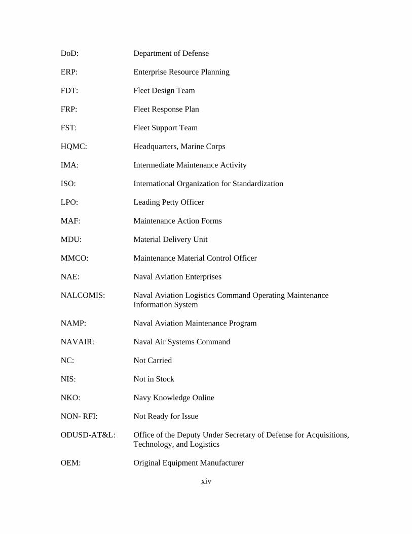


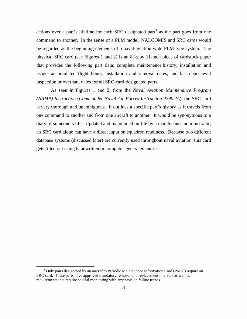


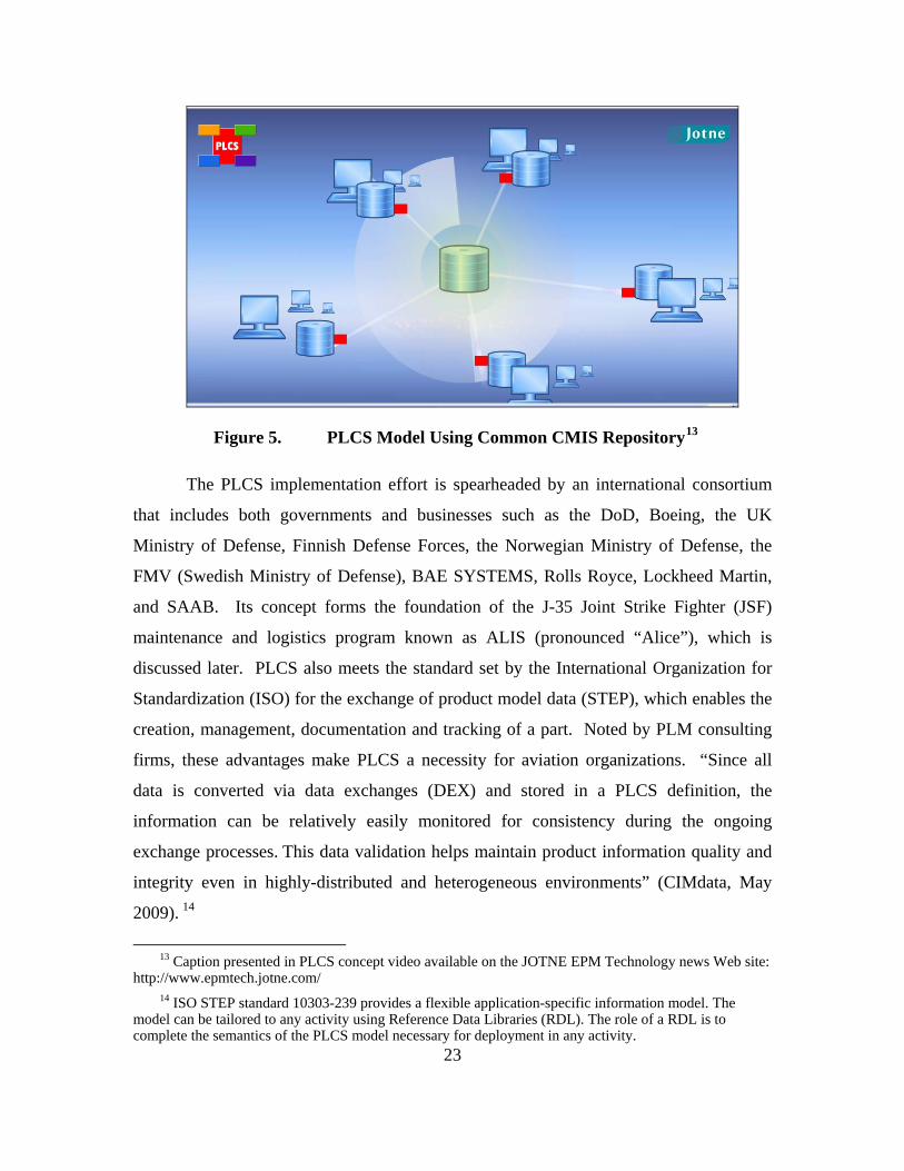


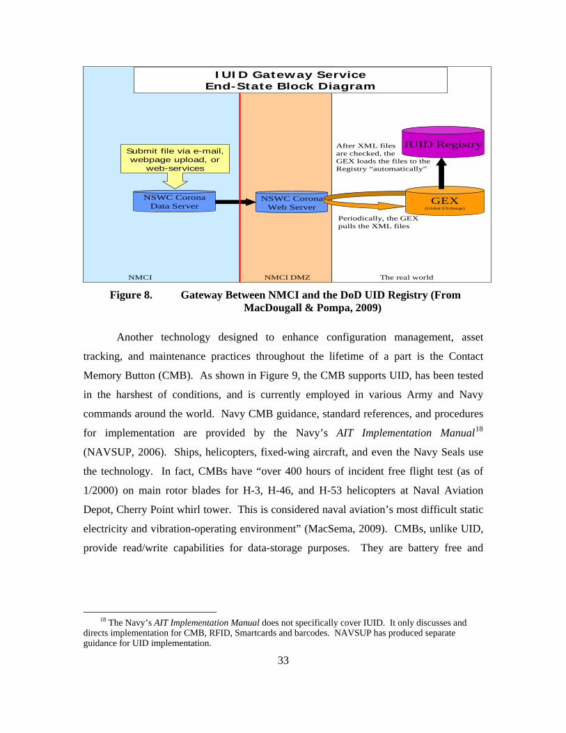


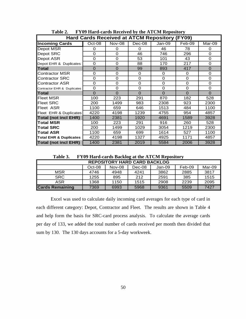

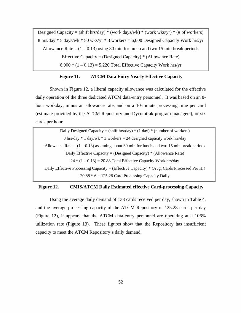
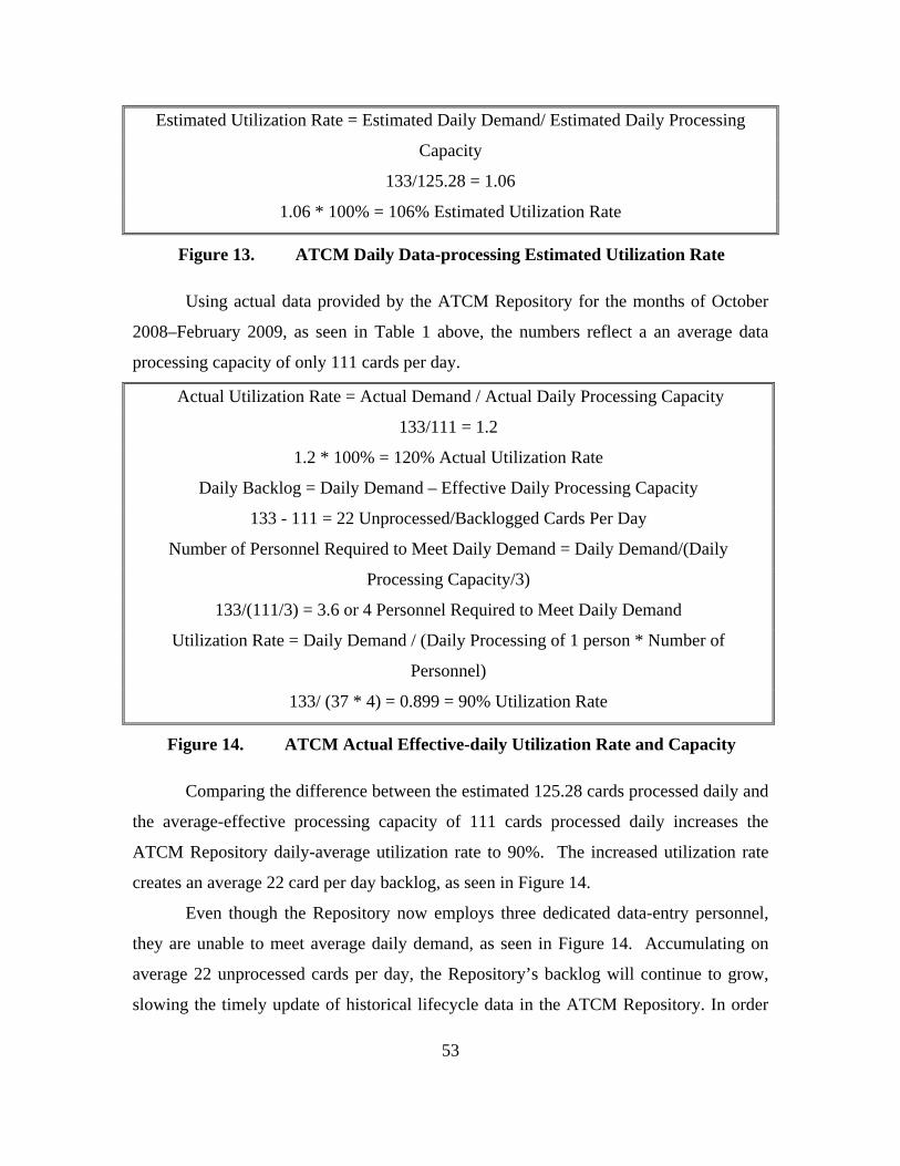
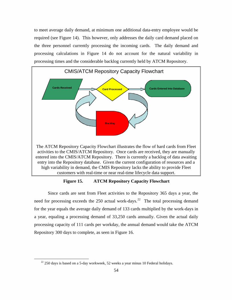

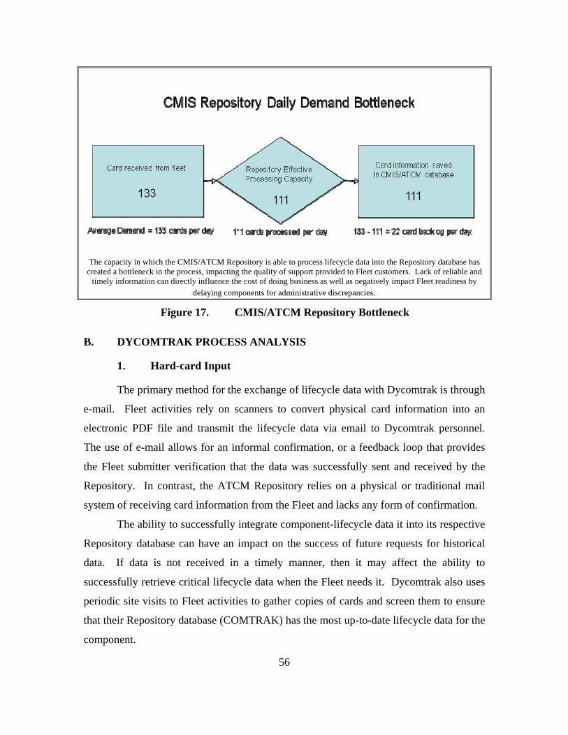


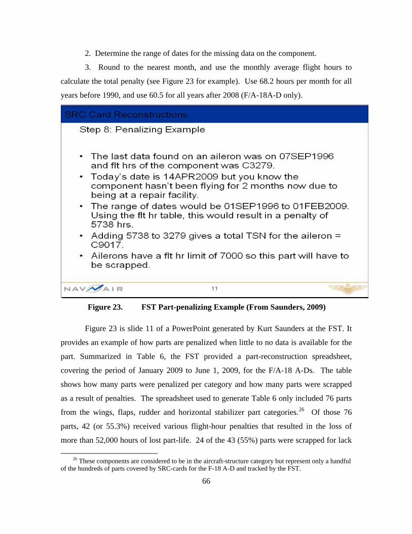


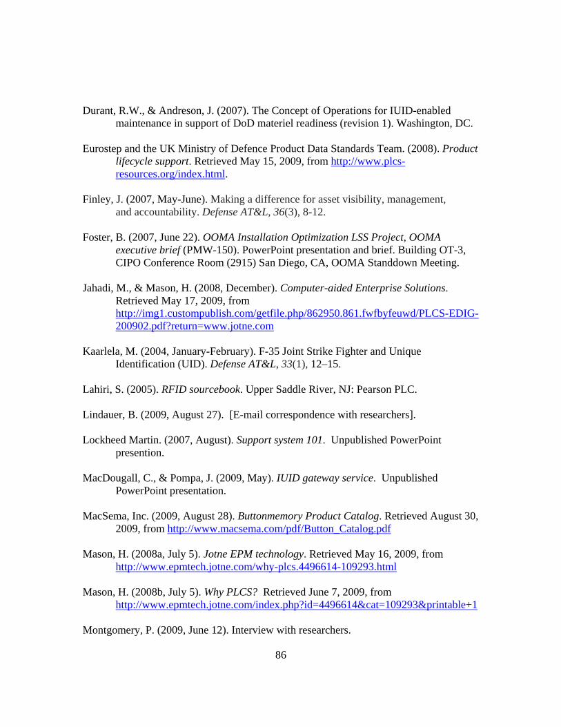


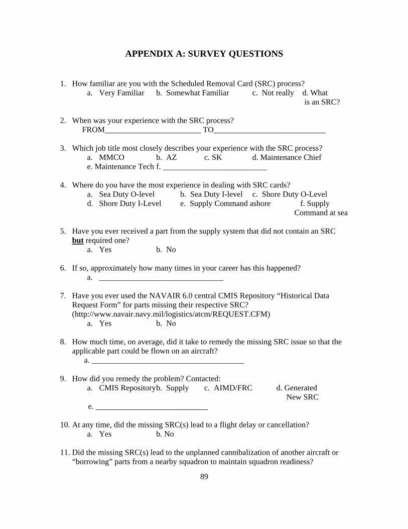


![[NAVAIR 00-80T-114]](https://static.documents.pub/doc/80x56/577d26651a28ab4e1ea1163e/navair-00-80t-114.jpg)
