[SGML Version - See Change Record ] TECHNICAL MANUAL NAVAL SHIPBOARD KETTLE, STEAM DISTRIBUTION STATEMENT B: DISTRIBUTION AUTHORIZED TO U.S. GOVERNMENT AGENCIES ONLY; ADMINISTRATIVE/OPERATIONAL USE; DATE OF PUBLICATION. OTHER REQUESTS SHALL BE REFERRED TO THE NAVAL SEA SYSTEMS COMMAND (SEA-0982) WARNING: THIS DOCUMENT CONTAINS TECHNICAL DATA WHOSE EXPORT IS RESTRICTED BY THE ARMS EXPORT CONTROL ACT (TITLE 22. U.S.C. SEC.2751 ET. SEQ.) OR EXECUTIVE ORDER 12470. VIOLATIONS OF THESE EXPORT LAWS ARE SUBJECT TO SEVERE CRIMINAL PENALTIES. DESTRUCTION NOTICE: DESTROY BY ANY METHOD THAT WILL PREVENT DISCLO- SURE OF CONTENTS OR RECONSTRUCTION OF THE DOCUMENT. S6151-BR-MMO-010 0910-LP-593-6100 REVISION 2 TITLE-1 / (TITLE-2 Blank)@@FIpgtype@@TITLE@@!FIpgtype@@ @@FIpgtype@@TITLE@@!FIpgtype@@ PUBLISHED BY DIRECTION OF COMMANDER, NAVAL SEA SYSTEMS COMMAND 17 SEP 1990
Transcript
[SGML Version - See Change Record ]TECHNICAL MANUAL
NAVAL SHIPBOARD KETTLE,STEAM
DISTRIBUTION STATEMENT B: DISTRIBUTION AUTHORIZED TO U.S. GOVERNMENTAGENCIES ONLY; ADMINISTRATIVE/OPERATIONAL USE; DATE OF PUBLICATION.OTHER REQUESTS SHALL BE REFERRED TO THE NAVAL SEA SYSTEMS COMMAND(SEA-0982)
WARNING: THIS DOCUMENT CONTAINS TECHNICAL DATA WHOSE EXPORT ISRESTRICTED BY THE ARMS EXPORT CONTROL ACT (TITLE 22. U.S.C. SEC.2751 ET.SEQ.) OR EXECUTIVE ORDER 12470. VIOLATIONS OF THESE EXPORT LAWS ARESUBJECT TO SEVERE CRIMINAL PENALTIES.
DESTRUCTION NOTICE: DESTROY BY ANY METHOD THAT WILL PREVENT DISCLO-SURE OF CONTENTS OR RECONSTRUCTION OF THE DOCUMENT.
PUBLISHED BY DIRECTION OF COMMANDER, NAVAL SEA SYSTEMS COMMAND
17 SEP 1990
TITLE-2@@FIpgtype@@BLANK@@!FIpgtype@@
RECORD OF CHANGESCHANGE NO. DATE TITLE OR BRIEF DESCRIPTION ENTERED BY
NOTE
THIS TECHNICAL MANUAL (TM) HAS BEEN DEVELOPED FROM AN INTELLIGENT ELECTRONICSOURCE KNOWN AS STANDARD GENERALIZED MARKUP LANGUAGE (SGML). THERE IS NOLOEP. ALL CHANGES, IF APPLICABLE, ARE INCLUDED. THE PAGINATION IN THIS TM WILL NOTMATCH THE PAGINATION OF THE ORIGINAL PAPER TM; HOWEVER, THE CONTENT IS EXACTLYTHE SAME. ANY CHANGES RECEIVED AFTER RECEIPT OF THIS TM WILL ONLY FIT IN THISPAGINATED VERSION.
The Groen TDB/7 is a table top, tilting, steam jacketed kettle with a thermostatically controlled, self-contained, electrically heated steam supply and appropriate controls, all mounted on a sturdy base. Model TDB/7is available in 20 or 40-quart capacity.
The body of the TDB/7 Kettle is constructed of stainless steel welded into one solid piece. the kettle is fur-nished with a reinforced rim and a butterfly shaped pouring lip and has a steam jacket rated for pressures up to50 PSI. Finish of the kettle is 180 emergy grit on the inside and bright semi-deluxe on the outside. Bottom-heavydesign causes the kettle to return from tilted to upright position when released. Pouring height allows the fillingof pans up to 4 inches high on a table top.
A built-in steam generator, sized for a kettle capacity and heated by electricity, feeds steam into the jacket.″Airless″ operation of the steam jacket permits uniform, efficient heating at temperatures as low as 150°F and ashigh as 298°F. In addition to the adjustable thermostat for operating control, the unit has a tilt cut-off switch,safety valve, and high-limit thermostat as safety features and a pilot lamp, pressure gauge, and gauge glass formonitoring the operation of the kettle.
Only a single electrical connection is required. The unit may be ordered for use with single or three phase,208, 240, or 480 volt power.
KETTLE CHARACTERISTICS
TDB/7-20 TDB/7-40
Kettle Capacity 20 qts. 18.8/ 40 qts. 37.6/Jacket Capacity 4 qts. 3.7/ 5 qts. 4.7/Diameter 14″ 36 cm 16 1/2″ 42 cmDepth 11″ 28 cm 14 1/4″ 36 cmK.W. at 208 V 6.3 10.8K.W. at 240 V 6.3 12.0K.W. at 480 v 6.3 12.0Base Width 24″ 60 cm 24″ 60 cmBase Depth 16″ 41 cm 16″ 41 cm
Optional equipment available with any of the models:
1. Stand that supports the unit and holds a pan in position for filling
2. Lift-off cover
3. Basket inserts
4. Fill faucet with bracket
5. Manual stirrers
6. Motor driven agitator
S6151-BR-MMO-010
1-1
Unpacking The Kettle
The unit will arrive completely assembled in a box. Immediately upon receipt, inspect the box carefully forexterior damage and then open the container. Inspect the unit for concealed damage, Report any shipping dam-age or incorrect shipments to the delivery agent.
A warranty registration card will be attached to the kettle. Fill out this card and mail it to Groen. Also writedown the model number, serial number, and installation date of your unit and file this information for future ref-erence. Space for these entries is provided at the top of the Maintenance and Service Log on Page 17.
To remove the kettle from the box, cut the polyester straps around the box. Detach the sides of the box fromthe skid, then pull the box up off the unit, taking care to avoid damage or injury by staples left in the box walls.When installation is to begin, cut the straps holding the kettle on the skid and lift the kettle straight up off theskid. Examine the packing materials to make sure no loose parts are discarded with the materials.
Installation
Your Groen Kettle is provided with all internal wiring complete and ready for final connection. A wiring dia-gram is furnished on the inside of the control housing service panel. Any mechanical or electrical changes mustbe approved by Groen’s Food Service Engineering Department.
The completed unit has been operated at the factory to test all controls and heater elements.
WARNING
INSTALLATION OF THE KETTLE MUST BE DONE BY PERSONNELQUALIFIED TO WORK WITH ELECTRICITY. IMPROPER INSTALLA-TION CAN RESULT IN INJURY TO PERSONNEL AND/OR DAMAGETO EQUIPMENT.
S6151-BR-MMO-010
1-2
1. Set the kettle in place and level it. The base may be fastened to a table or work surface. Installation under aventilation hood is recommended.
2. Provide the proper electrical power supply as specified on the electrical information plate attached to theequipment. Observe local codes and/or The National Electrical Code in accordance with ANSI/NFPA 70-latestedition.
3. The equipment is shipped for three phase operation. Refer to the wiring diagram for single phase operation.
4. Bringing the electrical service through the entrance at the rear of the support housing, make a waterproof con-nection with the incoming lines. (A BX connection is not recommended.) ELECTRICALLY GROUND THEUNIT AT THE TERMINAL PROVIDED.
5. Confirm that the jacket water level is between the marks on the gauge glass. If the level is low, follow theinstructions under″Jacket Filling and Water Treatment″ in the ″Maintenance″ section of the manual.
6. The open end of the elbow on the outlet of the safety valve must be directed downward. If it is not, turn theelbow to the correct position.
7. Any mechanical or electrical change must be approved by the Groen Division Food Service EngineeringDepartment.
Initial Start-Up
Now that the kettle has been installed, you should test it to ensure that the unit is operating correctly.
1. Remove all literature and packing materials from the interior and exterior of the unit.
2. Turn on the electrical service to the unit.
3. Put a small amount of water into the kettle.
4. Following″To Start Kettle″ instructions in the″Operation″ section of this manual (Page 7), begin heating thewater at the highest thermostat setting. The pilot light should come on immediately, and heating should con-tinue until the water boils.
5. To shut down the unit, turn the thermostat dial to″OFF″.
If the kettle functions as described above, it is ready for use. If the unit does not function as described, callyour local Groen Authorized Service Agent.
S6151-BR-MMO-010
1-3
Operation
The operator controls operation of the kettle with the thermostat dial. The dial turns electric power for theheating elements on or off and sets the operating temperature of the kettle.
A. To Start Kettle
1. EVERY DAY make sure that the jacket water level is between the marks on the gauge glass. If the level isbelow the lower mark, see″Jacket Filling and Water Treatment″ in the ″Maintenance″ section of this manual(Page 8-10).
2. Check the pressure gauge. If the gauge does not show 20 to 30 inches of vacuum (that is, a reading of 20 to30 below 0), see″Jacket Vacuum″ in the ″Maintenance″ section of this manual (Page 8).
3. Turn on the electrical power supply to the unit.
4. Turn the thermostat dial to the desired setting. Glowing of the red pilot light indicates that the kettle is heat-ing, and cycling of the light on and off indicates that the kettle is being held at the set temperature. Once ineach cycle the contactors in the support housing will make a clicking sound.
B. To Shut Down Kettle
1. Turn the thermostat dial to″OFF″.
2. For prolonged shut-down, or before cleaning the outside of the unit, shut off the power supply to the unit.
Sequence of Operation
The following ″action-reaction″ outline is provided to help the user understand the actual functioning of theequipment.
When the operator starts up the kettle by turning the operating thermostat dial from″OFF″ to a desired set-ting, the thermostat switch closes. This action lights the pilot lamp and causes the contactors to close, allowingpower to flow to the heating elements. When the temperature of the steam jacket reaches the value correspond-ing to the dial setting, the thermostat switch opens. This action turns off the pilot lamp and causes the contactorsto open, stopping the flow of power to the heaters. As soon as the thermostat senses that the kettle is coolingbelow the set point, the thermostat switch closes, the pilot lamp lights, the contactors close, and the heaters comeon again. On-off cycling continues, maintaining the kettle at the set temperature and resulting in the pilot lightcycling seen during normal operation.
Every time the kettle is tilted, the tilt cut-off switch interrupts the power supply to the heaters, so the heat-ing elements will not operate while they are not submerged in the jacket water. If steam pressure greater than 50PSI is generated in the jacket, the safety valve will open and relieve the excess pressure. In the event that thejacket water level gets too low and the heating elements overheat, the high-limit thermostat will open and shutoff power to the elements until the kettle cools.
Setting the operating thermostat dial to″OFF″ shuts down all control and heating circuits.
Maintenance & Cleaning
A. MAINTENANCE
S6151-BR-MMO-010
1-4
NOTE
CONTACT GROEN OR AN AUTHORIZED GROEN REPRESENTATIVEWHEN REPAIRS AND MAINTENANCE ARE REQUIRED.
1. Periodic Maintenance A Maintenance & Service Log is provided with the warranty information. Each timemaintenance is performed on your Groen equipment, enter the date on which the work was done, what was done,and who did it. File the log with the warranty.
Periodic inspection can minimize equipment down time and increase the efficiency of operation. The follow-ing points should be checked regularly.
a. The pressure/vacuum gauge should show a vacuum of 20 to 30 inches, when the kettle is cold. If it does not,see″Jacket Vacuum″ below.
b. The jacket water level should be between the marks on the gauge glass. If the level is low, see″Jacket Fill-ing and Water Treatment″ below.
c. Electrical wiring should be kept securely connected and in good condition.
d. The inside of the support housing should be kept clean.
e. At least twice a month, the safety valve should be checked to make sure that it works freely. When gaugepressure is about 5 PSI, lift the valve lever and quickly let it snap back into place. Steam should escape if thesafety valve is functioning property.
WARNING
DO NOT EXPOSE YOURSELF TO THE ESCAPING STEAM. A SEVEREBURN CAN RESULT ON EXPOSED SKIN.
f. At least twice a year grease the two trunnion bearings. If the bearings are loose or hard to turn, replace bothbearings.
2. Jacket Vacuum When the kettle is cold, a positive pressure reading or a reading around zero on the pressure/vacuum gauge indicates the pressure of air in the jacket. Air in the jacket slows down the heating of the kettle.To remove air:
a. Start the unit. (See the″Operation″ section of this manual.)
b. When the pressure/vacuum gauge reaches a positive pressure reading of 5 PSI, release the entrapped air andsteam by lifting the lever on the safety valve for about 1 second. Repeat this step, then let the valve lever snapback into the closed position.
S6151-BR-MMO-010
1-5
WARNING
AVOID ANY EXPOSURE TO THE STEAM BLOWING OUT OF THESAFETY VALVE. A SEVERE BURN CAN RESULT ON EXPOSED SKIN.
3. Jacket Filling and Water Treatment The jacket has been charged at the factory with the proper amount oftreated water. You may need to restore the water to its proper level, either because water was lost as steam dur-ing venting or because treated water was lost by draining. The procedure for adding water follows:
a. If you are replacing water lost as steam, use distilled water. If you are replacing treated water that ran out ofthe jacket, prepare more treated water as directed below.
b. Allow the kettle to cool. Turn the elbow on the safety valve counter clockwise (to avoid thread damage) untilthe opening of the elbow faces upward.
c. Open the safety valve and pour the water or treated water in at the elbow until the water level rises to a pointbetween the marks on the gauge glass. BEFORE YOU HEAT THE KETTLE FOR ANY PURPOSE, TURNTHE ELBOW CLOCKWISE UNTIL THE OPENING AGAIN FACES DOWNWARD.
d. Air introduced to the jacket during the filling operation must be removed to obtain efficient heating. See″Jacket Vacuum″ above.
Water Treatment Procedure
WARNING
TO AVOID INJURY, READ AND FOLLOW ALL PRECAUTIONSSTATED ON THE LABEL OF THE WATER TREATMENT COMPOUND.
(1). Fill the mixing container with the measured amount of water required. (See thetable below.) Distilledwater is recommended.
(2). Hang a strip of pH test paper on the rim of the container, with about 1 inch of the strip below the sur-face of the water.
(3) Measure the water treatment compound you will be using. (One way to do this is to add the compoundto the water from a measuring cup.)
(4) Stir the water continuously, while you slowly add water treatment compound, until the water reaches apH between 10.5 and 11.5. Judge the pH by frequently comparing the color of the test strip with the colorchart provided in the pH test kit. People mixing the treated water solution that are color blind must usean Electroanalytical Instrument to measure the pH level or have a person that is not color blind read thetest strip color level.
(5) Record the exact amounts of water and treatment compound used. These amounts may be used again, ifthe same sources of water and compound are employed to refill the jacket in the future. However, it isadvisable to check the pH every time treated water is prepared.
BEFORE REPLACING ANY PARTS, DISCONNECT THE UNIT FROMTHE ELECTRIC POWER SUPPLY.
All internal wiring is marked as shown on than circuit schematic drawings. Be sure that new components arewired in the same manner as the old components.
B. CLEANING
1. Suggested Tools
a. Detergent and sanitizer, or a combination cleaning-sanitizing agent like Micro-Quat from Economics Labora-tory.
b. Kettle brush
2. Precautions Before any cleaning operation, shut off the kettle by turning the thermostat dial to″OFF″, andshut off all electric power to the unit at a remote switch, such as the circuit breaker.
WARNING
KEEP WATER AND SOLUTIONS OUT OF CONTROLS AND ELECTRI-CAL EQUIPMENT. NEVER SPRAY OR HOSE THE SUPPORT HOUS-ING, ELECTRICAL CONNECTIONS, ETC.
WARNING
MOST CLEANERS ARE HARMFUL TO THE SKIN, EYES, MUCOUSMEMBRANES AND CLOTHING. PRECAUTION SHOULD BE TAKENTO WEAR RUBBER GLOVES, GOGGLES OR FACE SHIELD ANDPROTECTIVE CLOTHING. THESE ARE MINIMUM PRECAUTIONSTO BE TAKEN. CAREFULLY READ DIRECTIONS AND ALL WARN-INGS ON THE LABEL OF THE CLEANER TO BE USED.
3. Procedure
a. Clean all food-contact surfaces as soon as possible after use, preferably while the kettle is still hot. If the unitis in continuous use, thoroughly clean and sanitize both interior and exterior at least once every 12 hours.
S6151-BR-MMO-010
1-7
b. Scrape and flush out large amounts of food residues. Be careful not to scratch the kettle with metal imple-ments.
c. Prepare a hot solution of the detergent/cleaning compound as instructed by the supplier. Clean the unit thor-oughly. A cloth moistened with cleaning solution can be used to clean controls, control housings, electricalconduits, etc.
d. Rinse the kettle thoroughly with hot water, then drain completely.
e. As part of the daily cleaning program, clean all external and internal surfaces that may have been soiled.Remember to check such parts as the sides of the unit, control housing, etc.
f. To remove materials stuck to the equipment, use a brush, sponge, cloth, plastic or rubber scraper, or plasticwool along with the detergent solution. To minimize the effort required in washing, let the detergent solutionsit in the kettle and soak into the residue, or heat the detergent solution briefly. Do NOT use any abrasivematerials or metal implements that might scratch the surface, because scratches make the surface hard to cleanand provide places for bacteria to grow.
Do NOT use steel wool, which may leave particles imbedded in the surface and cause eventual corrosion andpitting.
g. The exterior of the unit may be polished with a recognized stainless steel cleaner like″Zepper″ from ZepManufacturing Company
h. When the equipment needs to be sanitized, use a sanitizing solution equivalent to one that supplies 200 partsper million available chlorine. Obtain advice on the best sanitizing agent from your supplier of sanitizingproducts. Following the supplier’s instructions, apply the sanitizing agent after the unit has been cleaned anddrained. Rinse off the sanitizer thoroughly.
CAUTION
NEVER LEAVE A CHLORINE SANITIZER in contact with stainless steelsurfaces LONGER THAN 30 MINUTES. Longer contact can cause corro-sion.
i. It is recommended that each piece of equipment be sanitized just before use by flushing thoroughly with sani-tizing solution.
j. If there is difficulty removing mineral deposits or a film left by hard water or food residues, clean the kettlethoroughly and then use a deliming agent, like Lime-Away from Economics Laboratory, in accordance withthe manufacturer’s directions. Rinse and drain the unit before further use.
k. If especially difficult cleaning problems persist, contact your cleaning product representative for assistance.The supplier has a trained technical staff with laboratory facilities to serve you.
Troubleshooting
Your Groen kettle is designed to operate smoothly and efficiently if properly maintained. However, the fol-lowing is a list of checks to make in the event of a problem. Wiring diagrams are furnished inside the servicepanel. If an item on the list is followed by an asterisk (*), the work should be done by a qualified service repre-sentative.
S6151-BR-MMO-010
1-8
Troubleshooting
SYMPTOM WHAT TO CHECK
Kettle will not heat,and pilot light willnot come on.
a. Electric power supply to the unitb. Control circuit fuses at the back of the support housing. Replace a blown fuse only with afuse of the same AMP rating.c. For loose or broken wires.*d. Tilt cut-off switch. (Page 13, Ref. 28).*e. That high-limit thermostat is closed (Page 13, Ref. 49).*f. Operation of variable thermostat (Page 13, Ref. 16).*
Kettle will not heat,but pilot light comeson.
a. Contactor (Page 13, Ref. 30).*b. Heater elements with ohmmeter for ground short or open element. If element is defective,call Groen.*
Kettle continues heat-ing after it reaches thedesired temperature.
a. Thermostat dial setting.b. Thermostat calibration (Page 13, Ref. 16).c. Thermostat operation. The thermostat should click when the dial is rotated above and belowthe setting for the temperature of the kettle. (Page 13, Ref. 16).d. Contactor, to determine whether it is de-energized. (Page 13, Ref. 30).*
Kettle stops heatingbefore it reaches thedesired temperature
a. Thermostat dial setting.b. Thermostat calibration (Page 13, Ref. 16).’c. Thermostat operation. The thermostat should click when the dial is rotated above and belowthe setting for the temperature of the kettle. (Page 13, Ref. 16).*
WARNING
USE ONLY FACTORY AUTHORIZED PARTS. SUBSTITUTING UNAUTHORIZED PARTS OR GENERICPARTS CAN CAUSE BODILY INJURY TO THE OPERATOR AND DAMAGE TO THE EQUIPMENT.
Kettle heats slowly. a. For air in the jacket. See″Jacket Vacuum″ in the ″Maintenance″ section of this manual (Page8 ).b. Heater elements with ohmmeter for ground short or open element. If an element is defective,call Groen.c. Voltage of main power source.*
Safety valve pops. a. For air in the jacket. See″Jacket Vacuum″ in the ″Maintenance″ section of this manual (Page8 ).b. Thermostat dial setting.c. Thermostat operation. Thermostat should click when the dial is rotated above and below thesetting for the temperature of the kettle. (Page 13, Ref. 16).*d. Safety valve. If the valve pops at pressures below 49 PSI, replace it (Page 13, ref. 23).e. Contactor, to determine whether it is de-energized. (Page 13, Ref. 30).
References
KLENZADE SALES CENTERECOLAB, Inc.370 WabashaSt. Paul, Minnesota 55102800/328-3663 or 612/293-2233
NATIONAL FIRE: PROTECTION ASSOCIATION60 Battery March ParkQuincy, Massachusetts 02269
S6151-BR-MMO-010
1-9
NFPA/54 Installation of Gas Appliances & Gas Piping
NFPA/70 The National Electric Code
NATIONAL SANITATION FOUNDATION3475 Plymouth Rd.Ann Arbor, Michigan 48106
ZEP MANUFACTURING1390 Lunt AvenueElk Grove Village, Illinois 60007
Parts List
(For units manufactured before June 1, 1990)
To order parts, contact your authorized Groen Service Agency. Supply the model designation, part descrip-tion, part number, and quantity desired.
S6151-BR-MMO-010
1-10
Parts List
(For units manufactured before June 1,1990)
To order parts, contact your authorized Groen Service Agency. Supply the model designation, part descrip-tion, part number, and quantity desired.
S6151-BR-MMO-010
1-11
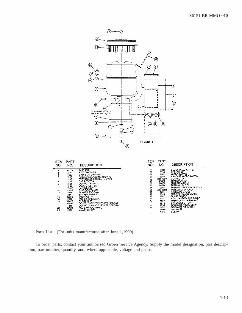
Parts List (For units manufactured after June 1,1990)
To order parts, contact your authorized Groen Service Agency. Supply the model designation, part descrip-tion, part number, quantity, and, where applicable, voltage and phase.
S6151-BR-MMO-010
1-12
Parts List (For units manufactured after June 1,1990)
To order parts, contact your authorized Groen Service Agency. Supply the model designation, part descrip-tion, part number, quantity, and, where applicable, voltage and phase.
S6151-BR-MMO-010
1-13
Wiring Diagrams for units manufactured before Sept 1, 1988
S6151-BR-MMO-010
1-14
TDB/7-20 208-240V 1 PH
TDB/7-20 208-240V 3 PH
S6151-BR-MMO-010
1-15
TDB/7-20 480V 1 PH
TDB/7-20 480V 3 PH
S6151-BR-MMO-010
1-16
TDB/7-20 208-240V 1 PH
TDB/7-40 208-240V 3 PH
S6151-BR-MMO-010
1-17
Wiring Diagrams for units manufactured after Sept 1, 1988 & before June 1, 1990
TDB/7-40 480V 1 PH
TDB/7-40 480V 3 PH
S6151-BR-MMO-010
1-18
TDB/7-20 208-240V 1 PH
TDB/7-20 208-240V 3 PH
S6151-BR-MMO-010
1-19
TDB/7-20 480V 1 PH
TDB/7-20 480V 3 PH
S6151-BR-MMO-010
1-20
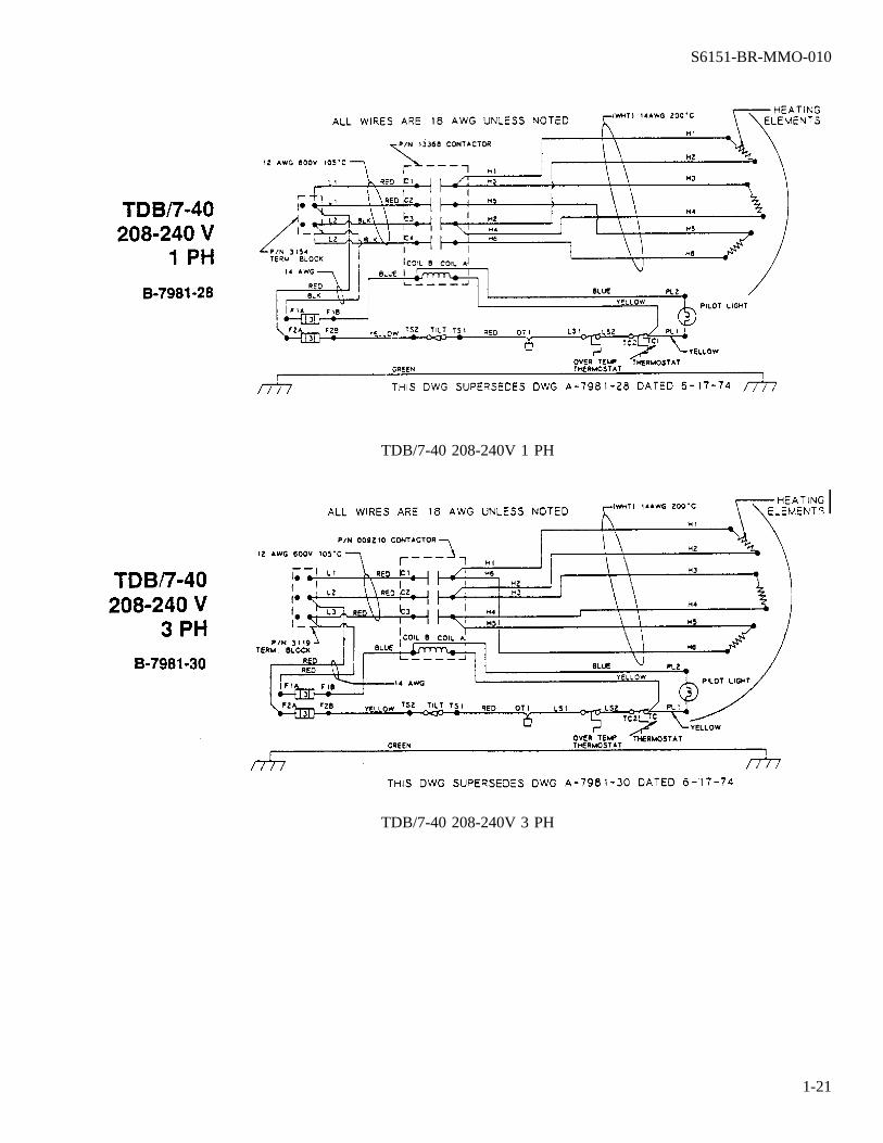
TDB/7-40 208-240V 1 PH
TDB/7-40 208-240V 3 PH
S6151-BR-MMO-010
1-21
Wiring Diagrams for units manufactured after June 1, 1990
TDB/7-40 480V 3 PH
TDB/7-40 480V 1 PH
S6151-BR-MMO-010
1-22
TDB/7-20 & TDB/7-40 208-240V 1&3 PH
TDB/7-20 & TDB/7-40 380/415V 3 PH
S6151-BR-MMO-010
1-23
TDB/7-20 & TDB/7-40 480V 1&3 PH
S6151-BR-MMO-010
1-24
Service Log
S6151-BR-MMO-010
1-25
Three-Year Limited Warranty To Commercial Purchasers*
(Domestic U.S. Sales Only)
Groen Foodservice Equipment (″Groen Equipment″) has been skillfully manufactured, carefully inspectedand packaged to meet rigid standards of excellence. Groen warrants its Equipment to be free from defects inmaterial and workmanship for thirty-six months from the date the Equipment is shipped from Groen’s factory(the ″warranty period″) on the following conditions and subject to the following limitations.
I. This warranty is limited to Groen Equipment sold to commercial purchaser/users (but not original equipmentmanufacturers) and installed in the continental United States and Hawaii. This warranty extends to subse-quent commercial owner/users only if the transfer of ownership does not involve movement or reinstallationof the product.
II. Product must be inspected and registered with Groen by buyer upon receipt. Damage during shipment is tobe reported to the carrier, and is not covered under this warranty.
III. Groen, or an authorized service representative, will repair or replace, at Groen’s sole election, any GroenEquipment, including but not limited to, drawoff valves, safety valves, gas and electric components, foundto be defective during the warranty period. This warranty includes all parts and labor costs for the warrantyperiod. As to warranty service in the territory described above, Groen will absorb portal to portal transpor-tation costs (time and mileage) during the first twelve months of the warranty period; however, buyers willbe liable for portal to portal transportation costs (time and mileage) during the remaining twenty-four monthsof the warranty period.
IV. This warranty does not cover normal maintenance, calibration, or regular adjustments as specified in oper-ating instructions or manuals (see operating manual of specific product); consumable parts such as scraperblades, gaskets, or packing; and/or labor involved in moving adjacent objects to gain access to the Equip-ment. This warranty does not cover defects caused by improper storage or handling prior to placing theEquipment; malfunction due to improper installation; damage caused by poor water quality (see recom-mended water standards); or the results of abuse, careless operation, or improper maintenance of the Equip-ment.
V. THIS WARRANTY IS EXCLUSIVE AND IS IN LIEU OF ALL OTHER WARRANTIES, EXPRESSEDOR IMPLIED, INCLUDING ANY IMPLIED WARRANTY OF MERCHANTABILITY OR FITNESS FORA PARTICULAR PURPOSE, EACH OF WHICH IS HEREBY EXPRESSLY DISCLAIMED. THE REM-
S6151-BR-MMO-010
1-26
EDIES DESCRIBED ABOVE ARE EXCLUSIVE AND IN NO EVENT SHALL GROEN BE LIABLE FORSPECIAL, CONSEQUENTIAL OR INCIDENTAL DAMAGES FOR THE BREACH OR DELAY IN PER-FORMANCE OF THIS WARRANTY.
VI. Groen Equipment is for commercial use only. If sold as a component of another (O.E.M.) manufacturer’sequipment, or if used as a consumer product, such Equipment is sold AS IS and without any written war-ranty.