Page 1
Naval Surface Warfare Center
Carderock Division
West Bethesda, MD 20817-5700
NSWCCD-61-TR-2015/31
Published
November 2015
Month YYYY
Approved for public release; Distribution is unlimited.
Survivability, Structures, Materials, and Environmental Department
Technical Memorandum
Simulation of Weld Mechanical Behavior to Include Welding-Induced Residual Stress and Distortion: Coupling of SYSWELD and Abaqus Codes
by
Charles R. Fisher, Ph.D.
Ken Nahshon, Ph.D.
NS
WC
CD
-61-T
R–2
01
5/3
1
Sim
ula
tion o
f W
eld
Mechan
ical B
eh
avio
r to
Inclu
de W
eld
ing-I
nduced
Resid
ua
l S
tress a
nd D
isto
rtio
n:
Coup
ling o
f S
YS
WE
LD
an
d A
ba
qus C
odes
Page 2
Naval Surface Warfare Center
Carderock Division
West Bethesda, MD 20817-5700
NSWCCD-61-TR-2015/31
Published
November 2015
Month
Survivability, Structures, Materials, and Environmental Department
Technical Memorandum
Simulation of Weld Mechanical Behavior to Include Welding-Induced Residual Stress and Distortion:
Coupling of SYSWELD and Abaqus Codes
by
Charles R. Fisher, Ph.D.
Ken Nahshon, Ph.D.
Approved for public release; Distribution is unlimited.
Page 3
i Standard Form 298 (Rev. 8-98)
Prescribed by ANSI Std. Z39.18
REPORT DOCUMENTATION PAGE Form Approved
OMB No. 0704-0188
Public reporting burden for this collection of information is estimated to average 1 hour per response, including the time for reviewing instructions, searching existing data sources, gathering and maintaining the data needed, and completing and reviewing this collection of information. Send comments regarding this burden estimate or any other aspect of this collection of information, including suggestions for reducing this burden to Department of Defense, Washington Headquarters Services, Directorate for Information Operations and Reports (0704-0188), 1215 Jefferson Davis Highway, Suite 1204, Arlington, VA 22202-4302. Respondents should be aware that notwithstanding any other provision of law, no person shall be subject to any penalty for failing to comply with a collection of information if it does not display a currently valid OMB control number. PLEASE DO NOT RETURN YOUR FORM TO THE ABOVE ADDRESS.
1. REPORT DATE (DD-MM-YYYY)
05-11-2015
2. REPORT TYPE
Technical Report
3. DATES COVERED (From - To)
Dec 2013 – July 2015 4. TITLE AND SUBTITLE
Simulation of Weld Mechanical Behavior to Include Welding-
Induced Residual Stress and Distortion: Coupling of SYSWELD and
Abaqus Codes
5a. CONTRACT NUMBER N/A 5b. GRANT NUMBER N/A 5c. PROGRAM ELEMENT NUMBER
N/A 6. AUTHOR(S)
Charles R. Fisher, Ph.D.
Ken Nahshon, Ph.D.
5d. PROJECT NUMBER
N/A 5e. TASK NUMBER
N/A 5f. WORK UNIT NUMBER N/A
7. PERFORMING ORGANIZATION NAME(S) AND ADDRESS(ES) AND ADDRESS(ES) 8. PERFORMING ORGANIZATION REPORT NUMBER
NSWCCD-61-TR-2015/31 Naval Surface Warfare Center, Carderock Division
9500 MacArthur Boulevard, West Bethesda, MD 20817-5700
9. SPONSORING / MONITORING AGENCY NAME(S) AND ADDRESS(ES) 10. SPONSOR/MONITOR’S ACRONYM(S)
Naval Surface Warfare Center, Carderock Division
9500 MacArthur Boulevard
West Bethesda, MD 20817-5700 11. SPONSOR/MONITOR’S REPORT NUMBER(S) N/A
12. DISTRIBUTION / AVAILABILITY STATEMENT
Distribution Statement A: Approved for public release; distribution is unlimited.
13. SUPPLEMENTARY NOTES
14. ABSTRACT:
A new computational procedure for including welding-induced residual stresses and
distortions from weld simulations in the SYSWELD software code in structural Finite
Element Analysis (FEA) simulations performed in the Abaqus FEA code is presented. The
translation of these results is accomplished using a newly developed Python script. Full
details of extracting the results from SYSWELD, translating these results using the
newly developed Python script, and including the results in Abaqus are provided through
an illustrative example analysis of a butt-welded aluminum plate. The development of
this capability is motivated by the Navy’s increased use of lightweight aluminum
structures where including the effects of welding in structural components can be
critical to understanding structural response. The integration of SYSWELD and Abaqus
enables Code 60 engineers to increase the efficiency of design through the integrated
computational materials engineering (ICME) paradigm, which emphasizes the use of
computational tools to understand design performance, while minimizing the amount of
traditional physical testing. This project is part of a program entitled “Integrated
Computational Design and Analysis – Aluminum Ship Materials and Structural Performance
(Al ICDA).”
15. SUBJECT TERMS
Computational simulation, SYSWELD, Abaqus, residual stress, distortion
16. SECURITY CLASSIFICATION OF: 17. LIMITATION OF ABSTRACT
18. NUMBER OF PAGES
23
19a. RESPONSIBLE PERSON
Charles Fisher
a. REPORT
UNCLASSIFIED b. ABSTRACT
UNCLASSIFIED
c. THIS PAGE
UNCLASSIFIED 19b. TELEPHONE NUMBER
(301) 227-4969
Page 4
NSWCCD-61-TR-2015/31
ii
CONTENTS
Page
FIGURES ....................................................................................................................................... iii
ADMINISTRATIVE INFORMATION ........................................................................................ iv
ACKNOWLEDGEMENTS ........................................................................................................... iv
EXECUTIVE SUMMARY .............................................................................................................6
BACKGROUND .............................................................................................................................6
Overview of SYSWELD Software ......................................................................................7
Overview of Abaqus Software .............................................................................................7
PROCEDURE ..................................................................................................................................7
SYSWELD Results Preparation ..........................................................................................8
SYSWELD Mesh Output ...............................................................................................8
Distortion Output ...........................................................................................................9
Stress Output ................................................................................................................11
Running Translation Script ................................................................................................12
USAGE EXAMPLE ......................................................................................................................13
Translating Results.............................................................................................................14
Using Initialized Local Weld Model in Structural FEA ....................................................15
CONCLUSIONS............................................................................................................................16
REFERENCES ..............................................................................................................................18
APPENDIX ....................................................................................................................................19
DISTRIBUTION............................................................................................................................23
Page 5
NSWCCD-61-TR-2015/31
iii
FIGURES
Page
Figure 1. Screen shots of the Visual Mesh function within SYSWELD showing
how to a) export mesh and b) save to the appropriate Abaqus file
format. ............................................................................................................................8
Figure 2. Screen shots of the Visual Viewer function within SYSWELD
showing how to view the ‘Contour’ window used to display distortion
and stress levels among other predicted properties. .......................................................9
Figure 3. Screen shots of the ‘Contour’ window showing how to display the
mesh displacement depending on if the ‘Tree’ menu, highlighted with
dotted red boxes, is set to a) Quantity or b) Entity.......................................................10
Figure 4. Screen shots of the Visual Viewer function showing a) drop-down
menus to save an ASCII contour (text-based file) and b) different
properties available to be saved as such. For this case,
DISPLACEMENTS_NOD_X (or Y or Z), as highlighted by the dotted
red box, are required. ...................................................................................................10
Figure 5. Screen shots of the ‘Contour’ window showing how to display the
predicted stress depending on if the ‘Tree’ menu, highlighted with
dotted red boxes, is set to a) Quantity or b) Entity.......................................................11
Figure 6. Screen shots of the Visual Viewer function showing the different
properties available to be saved as an ASCII contour (text-based file).
To save stress data, STRESSES_ELE_XX (or YY, ZZ, XZ, YZ, or XY),
as highlighted by the dotted red box, are required. ......................................................12
Figure 7. SYSWELD-generated model of a three-pass, Al 5052 GMA weld joint
showing the initial mesh and clamping conditions. .....................................................14
Figure 8. Comparison of Von Mises stress levels from a) SYSWELD simulation
output values and b) same values translated to Abaqus FEA. Minor
color variations are due to differences in contour coloring. ........................................15
Figure 9. Embedded weld with initial residual stresses, determined by
SYSWELD, in global shell mesh a) prior to a loading simulation in
Abaqus, and b) post-loading in Abaqus. Notice the stresses in the weld
and global shell mesh under uniaxial tension loading along stiffener
direction. Coupling from global shell mesh to local weld mesh is fully
automated using one-way. ...........................................................................................16
Page 6
NSWCCD-61-TR-2015/31
iv
ADMINISTRATIVE INFORMATION
The work described in this report was performed by the Welding, Processing, and
Nondestructive Evaluation Branch (Code 611) and the Hull Response and Protection Branch
(Code 664) of the Survivability, Structures, Materials, and Environmental Department of the
Naval Surface Warfare Center, Carderock Division (NSWCCD). The work was funded in FY14
by Section 219 internal research funds under a project entitled “Integrated Computational Design
and Analysis – Aluminum Ship Materials and Structural Performance” and was overseen by Jack
Price, Director of Research at NSWCCD. This cross-division program was initiated to enable
the development of a seamless computational capability to perform calculations from welding
through structural response and failure.
ACKNOWLEDGEMENTS
The authors would like to thank Maria Posada and Matthew Sinfield (NSWCCD Code
611) for their technical assistance in the completion of this work. In addition, Brian Shula and
Chandrashekhar Kanetkar, Senior Applications Engineers in the Welding Division at ESI Group
– North America, served as external collaborators for the computational modeling effort.
Page 7
NSWCCD-61-TR-2015/31
This page intentionally left blank
Page 8
NSWCCD-61-TR-2015/31
6
EXECUTIVE SUMMARY
A new computational procedure for including welding-induced residual
stresses and distortions from weld simulations in the SYSWELD software code in
structural Finite Element Analysis (FEA) simulations performed in the Abaqus
FEA code is presented. The translation of these results is accomplished using a
newly developed Python script. Full details of extracting the results from
SYSWELD, translating these results using the newly developed Python script, and
including the results in Abaqus are provided through an illustrative example
analysis of a butt-welded aluminum plate. The development of this capability is
motivated by the Navy’s increased use of lightweight aluminum structures where
including the effects of welding in structural components can be critical to
understanding structural response. The integration of SYSWELD and Abaqus
enables Code 60 engineers to increase the efficiency of design through the
integrated computational materials engineering (ICME) paradigm, which
emphasizes the use of computational tools to understand design performance,
while minimizing the amount of traditional physical testing. This project is part of
a program entitled “Integrated Computational Design and Analysis – Aluminum
Ship Materials and Structural Performance (Al ICDA).”
BACKGROUND
As a result of increasing requirements for high-speed vessels, the U.S. Navy is increasing
use of lightweight structures, most notably in aluminum-based construction, where welding-
induced stresses and distortions can have a significant impact on structural behavior. The effect
of these welding-induced quantities often manifest themselves on a structural level, such as crack
development with no appreciable global structural load as a result of residual stresses or
premature buckling under compressive loading. In combination with this, many of these high-
speed structures exhibit materials, welding configurations, and structural details that differ from
historical U.S. Navy structures. As such, it is difficult to perform evaluations or improve the
design of these structures using well-developed “rule of thumb” criteria.
Since a full testing program examining the performance of each detail under typical naval
shiploads is not economically feasible, extensive computations accompanied by targeted testing
are required for evaluation and development of new designs. However, in order to perform such
computations, an efficient method to include welding-induced stresses and initial distortions in
these computations is required. This approach, falling within the Integrated Computational
Materials Engineering (ICME) paradigm, hinges on both validation and verification (V&V) of
the applied methods and the seamless communication of the computational tools of interest.
Historically, computational tools for analyzing welding and structural behavior have been
used in an isolated setting. In the present effort, a process to transfer results from weld process
simulations, performed using the SYSWELD welding simulation Finite Element Analysis (FEA)
software package, to coupon and structural scale calculations, performed in the widely-utilized
Abaqus FE software package, is described. While Abaqus has been used extensively for
Page 9
NSWCCD-61-TR-2015/31
7
simulating the mechanical behavior of aluminum structural components [1-4], no documented
integration of SYSWELD and Abaqus was identified.
Overview of SYSWELD Software
SYSWELD is a commercially-available FEA software package developed by ESI Group
for use in thermo-mechanical and thermo-metallurgical welding process simulations. Specific
welding processes can be directly simulated with the ability to input welding parameters,
including travel speed, arc voltage/current, weld pool size, and clamping conditions. SYSWELD
uses material databases that contain the thermal, metallurgical, and mechanical material
properties for the materials being simulated. Though widely used and accepted for capturing the
welding process in steel, there are relatively few examples of SYSWELD used to simulate
aluminum welding processes [5-7]. The reader is referred to the SYSWELD Toolbox for full
details on the usage and input format for SYSWELD software [8].
Overview of Abaqus Software
Abaqus FEA is a widely utilized and commercially-available, general-purpose FE
software package developed by Dassault Systèmes. The software enables modeling of materials,
components, and assemblies under different loading conditions so that stress, strain, and other
relevant quantities can be determined. Abaqus analyses readily include pre-existing
material/structural states such as initial residual stresses and distortions. The reader is referred to
Abaqus FEA documentation for full details on the usage and input format for Abaqus software
[9].
PROCEDURE
The transfer of results from SYSWELD to Abaqus FEA is achieved using the post-
processing tools supplied with SYSWELD, along with available Abaqus input keywords. A
newly-developed script, SYSWELD_ABQ_field.py, performs this transfer (see Appendix for a
full code listing). A walk-through of the process is given below. A description of the process for
generating the necessary files from SYSWELD is described followed by instructions of using the
script and including the translated SYSWELD results in an Abaqus analysis.
The transfer of SYSWELD results to Abaqus involves several steps in both software
tools:
1. Generate output data of the field quantities of interest, namely stress and displacement,
using the SYSWELD post-processing module.
2. Transfer mesh from SYSWELD to Abaqus using SYSWELD’s *.inp mesh output
capability. Alternatively, SYSWELD can read in the starting Abaqus mesh. It is critical
that elemental and nodal numbering be preserved and that any mesh generated in Abaqus
be in the “flat” format; i.e., not utilize parts and assemblies. Alternatively, SYSWELD
analyses can be performed using a mesh imported from Abaqus.
3. Translate SYSWELD field quantities to Abaqus-interpretable format using
SYSWELD_ABQ_field script.
Page 10
NSWCCD-61-TR-2015/31
8
4. Run subsequent Abaqus FEA analysis with *INCLUDE keyword to include initial residual
stress and distortion input files generated by SYSWELD_ABQ_field script.
A full description of these steps is provided below.
SYSWELD Results Preparation
The output required for the translation script consists of a series of files tabulating each
stress component (XX, YY, ZZ, XY, XZ, YZ) for every element in the form
STRESSES_ELE_XX.TXT, each distortion component (X, Y, Z) in the form
DISTORTION_NOD_X.TXT, and, for most cases, a valid exported Abaqus mesh. The steps
described below document how to generate the necessary output text files from a SYSWELD
simulation using the graphical interface of Visual Environment 10.5 (including Visual Mesh,
Visual Weld, and Visual Viewer). The simulation results examined were generated using
SYSWELD 2015.
SYSWELD Mesh Output
The mesh from the original CAD file may have been modified during the weld modeling
process within SYSWELD. Therefore, after the simulation, open the <file name>.vdb file
within the Visual Mesh program of SYSWELD. To export the mesh, go to the ‘File’ menu and
click on ‘Export’ (see Figure 1a). This brings up a new window (see Figure 1b) enabling the
user to save the mesh in numerous file formats; in this case, ‘ABAQUS files (*.inp)’ should be
selected.
Figure 1. Screen shots of the Visual Mesh function within SYSWELD showing how
to a) export mesh and b) save to the appropriate Abaqus file format.
Page 11
NSWCCD-61-TR-2015/31
9
Distortion Output
The distortion of the mesh after the SYSWELD simulation can be viewed by opening the
<file name>_V_POST2000.fdb file within the Visual Viewer program of SYSWELD.
To view the distortion, go to the ‘Results’ menu and click on ‘Contour’ (see Figure 2). This
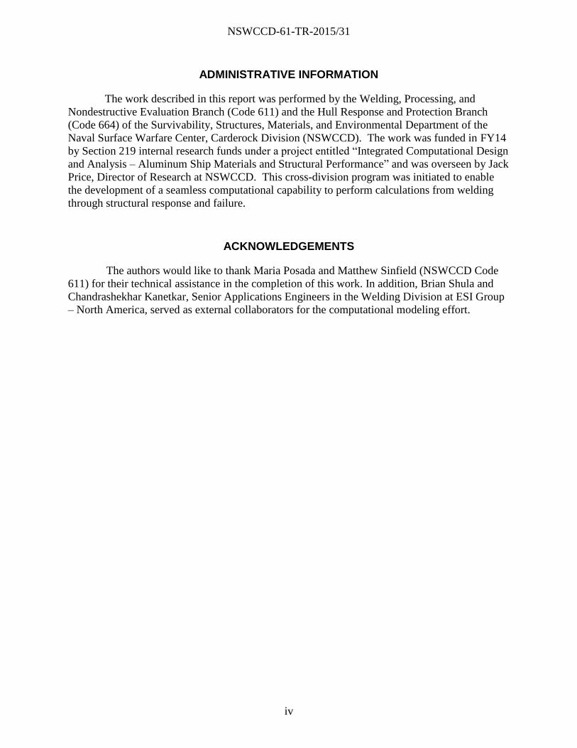
brings up a new window (see Figure 3). Depending on settings, the user must click differently
to obtain the same resulting views. Under the ‘Tree’ menu, if set to Quantity, open the
‘Kinematics’ drop down menu, and set the ‘Displacement’ drop down menu to either X, Y, or Z
based on the principle nodal direction under investigation (see Figure 3a). Under the ‘Tree’
menu, if set to Entity, open the ‘Node’ drop down menu, and set the ‘Displacement’ drop down
menu to either X, Y, or Z based on the principle nodal direction under investigation (see Figure
3b).
Figure 2. Screen shot of the Visual Viewer function within SYSWELD showing how
to view the ‘Contour’ window used to display distortion and stress levels
among other predicted properties.
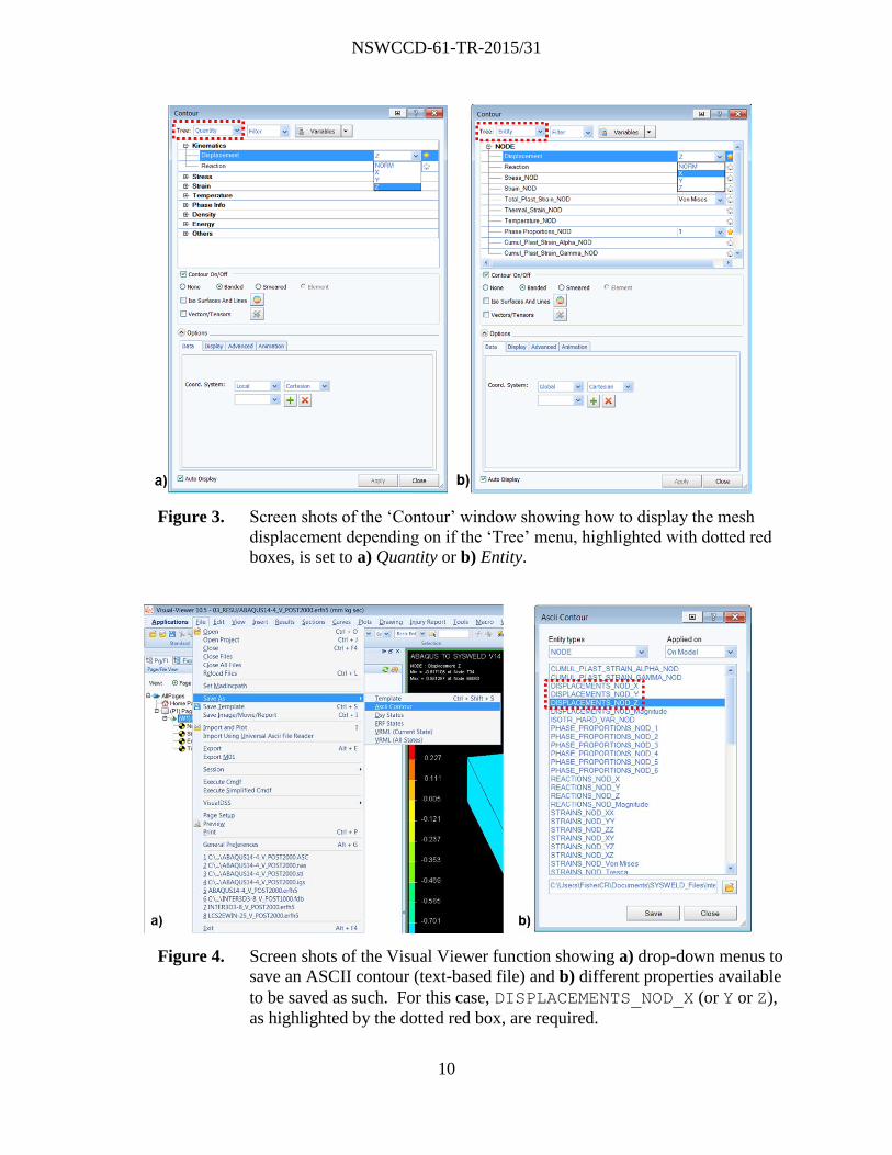
The distortion results can be output in text format by clicking to the final step of the
simulation. Next, go to the ‘File’ menu and click ‘Save As Ascii Contour’ (see Figure 4a).
This brings up a new window (see Figure 4b). Under the ‘Entity’ menu, ensure the text is set to
NODE. Finally, click DISPLACEMENTS_NOD_X (or Y or Z), and save the output data to an
appropriate location.
Page 12
NSWCCD-61-TR-2015/31
10
Figure 3. Screen shots of the ‘Contour’ window showing how to display the mesh
displacement depending on if the ‘Tree’ menu, highlighted with dotted red
boxes, is set to a) Quantity or b) Entity.
Figure 4. Screen shots of the Visual Viewer function showing a) drop-down menus to
save an ASCII contour (text-based file) and b) different properties available
to be saved as such. For this case, DISPLACEMENTS_NOD_X (or Y or Z),
as highlighted by the dotted red box, are required.
Page 13
NSWCCD-61-TR-2015/31
11
Stress Output
The predicted stress from the welding simulation can be viewed by opening the <file
name>_V_POST2000.fdb file within the Visual Viewer program of SYSWELD. Similar to
displaying the nodal distortion, to view the stress levels go to the ‘Results’ menu and click on
‘Contour’ (as in Figure 2) which brings up a new window. Depending on settings, the user must
click differently to obtain the same resulting views. Under the ‘Tree’ menu, if set to Quantity,
open the ‘Stress’ drop down menu, and set the second ‘Stress’ drop down menu to XX, YY, ZZ,
XZ, YZ, or XY based on the principle stress direction under investigation (see Figure 5a). Under
the ‘Tree’ menu, if set to Entity, open the ‘Solid’ drop down menu, and set the ‘Stress’ drop
down menu to XX, YY, ZZ, XZ, YZ, or XY based on the principle stress direction under
investigation (see Figure 5b).
Figure 5. Screen shots of the ‘Contour’ window showing how to display the predicted
stress depending on if the ‘Tree’ menu, highlighted with dotted red boxes, is
set to either a) Quantity or b) Entity.
The stress results can be output in text format by clicking to the final step of the
simulation. Next, go to the ‘File’ menu and click ‘Save As Ascii Contour’ (see Figure 4a);
this is the same as for distortion output. For stress, however, in the new window (see Figure 6)
which opens, ensure the text is set to SOLID under the ‘Entity’ menu. Finally, click
STRESSES_ELE_XX (or YY, ZZ, XZ, YZ, or XY), and save the output data to an appropriate
location.
Page 14
NSWCCD-61-TR-2015/31
12
Figure 6. Screen shot of the Visual Viewer function showing the different properties
available to be saved as an ASCII contour (text-based file). To save stress
data, STRESSES_ELE_XX (or YY, ZZ, XZ, YZ, or XY), as highlighted by
the dotted red box, are required.
Running Translation Script
Once the stress and distortion output is generated from SYSWELD, the
SYSWELD_ABQ_field.py may be run. All SYSWELD output must be in the same directory.
The script itself can be run either using Abaqus’ built-in Python shell or any external installation
of Python that includes the csv and argparse modules. The script was tested to work in
Abaqus 6.14 with no additional software beyond a valid Abaqus FEA installation.
The SYSWELD_ABQ_field.py script has separate functionalities for nodal and element
integration point quantities and must be executed twice: once for stress and once for distortion.
The stress and distortion quantities are handled as follows:
Residual stresses, described at element integration points, are processed and formatted
using the *INITIAL CONDITIONS, TYPE=STRESS Abaqus keyword. SYSWELD
generates an individual file for each component of stress (𝜎𝑥𝑥, 𝜎𝑦𝑦, 𝜎𝑧𝑧, 𝜎𝑥𝑦 , 𝜎𝑥𝑧 , 𝜎𝑦𝑧).
The script generates a standalone Abaqus input file, stress.inp, that provides the
individual stress components in a six-column vector that is tabulated for each element.
Page 15
NSWCCD-61-TR-2015/31
13
Initial distortions or displacements, a nodal quantity with three components (X, Y, Z) are
converted to the *IMPERFECTION, INPUT=FILENAME Abaqus keyword format.
SYSWELD generated an individual file for each component of displacement
(∆𝑥, ∆𝑦, ∆𝑧). A file displacement.csv is generated that assembles these individual
displacement components into a three-column vector associated with each node number.
The SYSWELD_ABQ_field.py script is invoked through a command-line driven interface using
the syntax:
abaqus python SYSWELD_ABQ_field.py -fieldType <displacement|stress>
-path <path to SYSWELD field data> -scaleFactor <SF>
The arguments describe:
fieldType: Field of interest. Stresses are six-value tensor quantities at each element
whereas initial displacements are three-value vectors at each node.
path: Path to Sysweld-generated stress or displacement data.
scaleFactor: Scale factor to convert SYSWELD units to units in Abaqus analysis
for field of interest.
A help description can be obtained by executing:
abaqus python SYSWELD_ABQ_field.py –h
The commands:
python SYSWELD_ABQ_field.py -fieldType stress –path
/myDirectory/results -scaleFactor 1e6
python SYSWELD_ABQ_field.py -fieldType displacement –path
/myDirectory/results -scaleFactor 0.001
will generate stress.inp and displacement.csv files using the SYSWELD stress and
displacement data located in /myDirectory/results. A multiplier of 1e6 and 0.001 will be
applied to all stress values and displacement values, respectively. It is the user’s responsibility to
ensure that consistent unit systems are maintained. If a component is not defined by the data
provided from SYSWELD, a null value is assumed to ensure either a three-column vector for
displacement or a six-column stress vector for stress is obtained.
It is strongly recommended that a static step be undertaken with the SYSWELD-
generated residual stresses and distortions to ensure precise equilibrium. Once this step is taken,
the Abaqus analysis of interest can be performed.
USAGE EXAMPLE
The transfer of SYSWELD results to Abaqus was demonstrated for a B2V.1 joint, which
is a single-V butt joint without a backing bar [10]. The simulated material was Al 5052 using the
gas-metal arc welding (GMAW) process. A simulation of the welding process of this joint was
conducted in SYSWELD and is documented in another NSWCCD report [11]. While this
specific weldment does not represent an actual shipboard application, it was selected because it
Page 16
NSWCCD-61-TR-2015/31
14
demonstrated numerous weld processing conditions, including multiple weld passes, flipping the
weldment, and a back-gouge, in order to validate the SYSWELD to Abaqus technique. Figure 7
shows a view of the mesh, clamping conditions, and the three weld passes, shown in purple,
pink, and gold coloring.
Figure 7. SYSWELD-generated model of an aluminum B2V.1 joint showing the
initial mesh and clamping conditions.
Translating Results
Once the SYSWELD output steps are complete, the SYSWELD_ABQ_field.py script is
run to generate a stress.inp file. This file is directly included in the Abaqus analysis including the
following keyword in the main input file:
*Include, input=stress.inp
A contour plot showing the final residual stress state from SYSWELD simulations and
the initial state of an Abaqus analysis using these stresses is show in Figure 8. Note that the
mesh was generated in SYSWELD, exported to Abaqus, and scaled from mm-kg-MPa to MKS
units. The stresses were translated accordingly. Prior to undertaking further Abaqus analysis, it is
strongly recommended that a static equilibrium step be performed to ensure exact static
equilibrium.
Page 17
NSWCCD-61-TR-2015/31
15
Figure 8. Comparison of Von Mises stress levels from a) SYSWELD simulation
output values and b) same values translated to Abaqus FEA. Minor color
variations are due to differences in contour coloring.
Using Initialized Local Weld Model in Structural FEA
With the ability to include initial residual stress and distortion from SYSWELD
simulations in Abaqus structural analyses, global loads can readily be transferred into the local
weld detail using the sub-modeling capability available in Abaqus FEA. This capability
automatically maps the edge displacements of the coarse global mode to edge boundary
conditions on the local model.
An example application of this is shown in Figure 9. The initial state of the local weld
and the unloaded state are shown in Figure 9a. As displacement is applied to the edges of the
global structural model, a complex stress state in the weld is observed to develop in Figure 9b.
Page 18
NSWCCD-61-TR-2015/31
16
This result is very different from the result obtained without including residual stresses from
welding due to the high level of these stresses relative to the stress induced by structural loading.
Figure 9. Embedded weld with initial residual stresses, determined by SYSWELD, in
global shell mesh a) prior to a loading simulation in Abaqus, and b) post-
loading in Abaqus. Notice the stresses in the weld and global shell mesh
under uniaxial tension loading along stiffener direction. Coupling from
global shell mesh to local weld mesh is fully automated using one-way.
CONCLUSIONS
A process and necessary software for translating SYSWELD results from inclusion in
Abaqus FEA structural analyses has been developed and its usage demonstrated the successful
integration of the two software programs. The application of this newly-developed capability to
structural analysis of a multi-pass aluminum weld illustrates the inability of structural FEA
Page 19
NSWCCD-61-TR-2015/31
17
calculations to capture local weld detail response. As failures often initiate at these locations, the
U.S. Navy is now able to investigate how the welding process modifies the resultant fracture and
fatigue behavior for structural components on its vessels.
Page 20
NSWCCD-61-TR-2015/31
18
REFERENCES
1. A. Belegundu, Shape Optimization of Plates to Mitigate the Effects of Air Blast Loading,
U.S. Army Research Office Final Report, 50490-EG.1, June 2009.
2. I. Scheider, M. Schödel, W. Brocks, and W. Schönfeld, Crack Propagation Analyses with
CTOA and Cohesive Model: Comparison and Experimental Validation, Engineering
Fracture Mechanics, 2006, Vol. 73, pg. 252-263.
3. J. Zhou, M. Hayden, and X. Gao, An Investigation of the Strain Rate and Temperature
Effects on the Plastic Flow Stress and Ductile Failure Strain of Aluminum Alloys 5083-
H116, 6082-T6, and a 5183 Weld Metal, Proceedings of the Institution of Mechanical
Engineers, Part C: Journal of Mechanical Engineering Science, 2013, Vol. 227, No. 5, pg.
883-895.
4. Xiaosheng Gao, Tingting Zhang, Matthew Hayden, and Charles Roe, Effects of the Stress
State on Plasticity and Ductile Failure of an Aluminum 5083 Alloy, International Journal
of Plasticity, 2009, Vol. 25, Issue 12, pg. 2366-2382.
5. J.D. Francis, Welding Simulations of Aluminum Alloy Joints by Finite Element Analysis,
Master’s Thesis at Virginia Polytechnic Institute and State University, Blacksburg, VA,
2002.
6. M. Zain-ul-abdein, D. Nelias, J.-F. Jullien, F. Boitout, L. Dischert, and X. Noe, Finite
Element Analysis of Metallurgical Phase Transformations in AA 6056-T4 and Their
Effects Upon the Residual Stress and Distortion States of a Laser-Welded T-Joint,
International Journal of Pressure Vessels and Piping, 2011, Vol. 88, pg. 45-56.
7. Z.H. Guo, X.Y. Ou, G.W. Shuai, and Y.H. Chen, Numerical Simulation of Temperature
Field for TIG Welding of Aluminum Alloy Sheet Based on SYSWELD, Advanced
Materials Research, 2012, Vol. 472-475, pg. 1945-1949.
8. SYSWELD Toolbox 2015, Weld and Heat Treatment Simulation Manual, ESI Group,
Farmington Hills, MI, USA.
9. ABAQUS (2015), ABAQUS Documentation, Dassault Systèmes, Providence, RI, USA.
10. MIL-STD-22D, Department of Defense Design Criteria: Welded Joint Design, 29 August
1979.
11. C.R. Fisher and K. Nahshon, SYSWELD Computational Modeling for Data Transfer to
Abaqus FEA Software, NSWCCD-61-TR-2015/32, November 2015.
Page 21
NSWCCD-61-TR-2015/31
19
APPENDIX: SYSWELD_ABQ_field.py CODE
# SYSWELD_ABQ_field.py
# Written by Ken Nahshon ([email protected] ), Naval Surface Warfare Center
# Carderock Division
# 27 July 2015
# This code is subject to all USC regulations. NSWCCD shall not be held liable for any use or
# misuse of this code. The code is stictly provided as-is.
# -----------------------------------------------------------------------------------------------
# Converts field quantities from SYSWELD to ABAQUS
# Input consists of a directory with SYSWELD results e.g. DISPLACEMENTS_NOD_X.txt etc and STRESSES_ELE_XX.txt
# Output consists of a file stress.inp consisting of:
#
# stress.inp: *INITIAL CONDITION pre-stress values. The stress file
# can be included using *Include, input=stress.inp
# or directly copied and pasted into the ABAQUS input file.
#
# displacement.csv: delta x, y, and z for moving nodal coordinates.
# ABAQUS can move the nodal coordinates
# using *IMPERFECTION input=displacement.csv
# -----------------------------------------------------------------------------------------------
# Usage:
#
# python SYSWELD_ABQ_field.py -fieldType <field_type> -path <path to SYSWELD files> -scaleFactor <scaleFactor>
#
# Where,
# field_type can be either 'stress' or 'displacement'. Currently, other fields are not supported
# scaleFactor is a floating point value multiplying the SYSWELD results to account for unit changes
# working_directory is the location of SYSWELD output files
#
# Example:
#
# python SYSWELD_ABQ_field.py -fieldType stress -scaleFactor 1e6 -path /runs/weldcalc/
#
# Will execute the script to generate a stress.inp file in /runs/weldcalc/ using the SYSWELD output located
# in that directory with stresses from SYSWELD multiplied by the scale factor 1e6
#
# -----------------------------------------------------------------------------------------------
import os
import csv
import sys
import argparse
def filesWithString(fileStr, directory):
"""Returns a list of filenames with fileStr in name in directory\n
Usage: filesWithString(fileStr, directory)"""
listing=os.listdir(directory)
return [elem for elem in listing if elem.find(fileStr)>0]
def openInputFile(inputFileName, readWriteOption):
"""Safe file open with exceptions"""
import sys
print 'Processing: ', inputFileName
try:
inputFile=open(inputFileName, readWriteOption)
return inputFile
except IOError as e:
print "Error in file open in openInputFile:\n"
print "I/O error({0}): {1}".format(e.errno, e.strerror)
except:
print "Unexpected error:", sys.exc_info()[0]
raise
def openCsv(fileName, commentChar = ('#', '!', '%'), **kwargs):
"""
Read a .csv file with fileName (string) and return a list of lines where each line is a list
of entries seperated by commas in fileName. Routine strips out lines beginning with
commentChars and additional whitespace. Additional comment markers can be included.
Usage: \n\n
parseCSVtoList(fileName, commentChar = ('#', '!', '%'))
"""
whitespace=(' ', '\t') # Define whitespace to ignore
f=openInputFile(fileName, 'r')
reader=csv.reader(f, **kwargs)
lineCount=0
inputData=[]
for row in reader:
if (len(row) == 0) or (row[0][0] in commentChar): # Check for comment characters and skip entire line
continue # Skip empty lines
else:
Page 22
NSWCCD-61-TR-2015/31
20
# Eliminate additional whitespaces
for char in whitespace:
row=[row[index].replace(char, "") for index in range(0, len(row))]
inputData.append(row)
lineCount += 1
return inputData
# ********************************************************************************
# MAIN CODE
# ********************************************************************************
# Show title info
titleBlock = """\n*************************************************************************
\nSYSWELD_ABQ_field.py, a tool to convert SYSWELD fields to ABAQUS formats.
Currently supports stress and displacment types.
\n*************************************************************************"""
#print titleBlock
parser = argparse.ArgumentParser(description=titleBlock)
parser.add_argument('-fieldType', required=True, metavar=('<displacement|stress>'), type=str, nargs=1,
help='Specify field type')
parser.add_argument('-path', required=True, metavar=('<Path to SYSWELD field data>'), type=str, nargs=1,
help='Specify directory for SYSWELD files')
parser.add_argument('-scaleFactor', required=True, metavar=('<SF>'), type=float, nargs=1, help='Specify scale
factor for field')
parser._optionals.title = "Flag arguments"
# Parse arguments
args = parser.parse_args()
# Get command line input
fieldType = args.fieldType[0]
scaleFactor = args.scaleFactor[0]
directory = args.path[0]
# Make sure directory exists
if os.path.exists(directory) is False:
print '\n*** Fatal Error, %s is not a valid path ***' %directory
sys.exit(0)
# Make sure / is last character in directory name
#if directory[-1] != '/':
# directory = directory + '/'
# Precalculation output
print '\nField type: %s' %fieldType
print 'Multiplying SYSWELD %s by scale factor: %s' %(fieldType, scaleFactor)
print 'Working directory: %s\n' %directory
# Switch to working directory
os.chdir(directory)
# --------------------------
# Set up valid field types, directions
# --------------------------
#
# Valid field types
fieldList = ['displacement', 'stress']
# List of directions for tensors (elements)
directionList=['XX', 'YY', 'ZZ', 'XY', 'YZ', 'ZX']
# List of directions for nodes
nodalDirectionList=['X', 'Y', 'Z']
# Check for supported field type, set file prefix for SYSWELD. If not supported, exit.
if fieldType == 'stress':
prefix = 'STRESSES_ELE_'
elif fieldType == 'displacement':
prefix = 'DISPLACEMENTS_NOD_'
else:
print '** ERROR: following field type is not supported: ', fieldType
sys.exit()
# Perform actions based on field type
# Stress translation
if fieldType == 'stress':
# Set a dictionary of stress values, read stresses from direction if file exists
stress = dict()
for direction in directionList:
fileName = prefix + direction + '.txt'
Page 23
NSWCCD-61-TR-2015/31
21
if fileName in os.listdir(directory):
data=openCsv(directory+fileName, delimiter='\t', skipinitialspace = 'True')
# Strip header off data file. Currently, SYSWELD fills first 8 lines
data=data[8:]
# Read element list
elList = [ int(dataLine[0]) for dataLine in data]
# Read stresses, break into directions using dictionary
stress[direction] = [float(dataLine[1])*scaleFactor for dataLine in data]
numElements = len(elList)
# Backfill with zeroes for stress components that don't exist
for direction in directionList:
if direction not in stress.keys():
stress[direction] = [0.0 for line in range(0, numElements)]
# write out data as six column vector
with open(directory + 'stress.inp', 'wt') as f:
f.write('**Autogenerated prestress from SYSWELD\n')
f.write('*Initial Conditions, type=' + fieldType + '\n')
for i in range(0,numElements):
line = '{0}, {1}, {2}, {3}, {4}, {5}, {6}\n'.format(str(elList[i]),
str(stress['XX'][i]), str(stress['YY'][i]), str(stress['ZZ'][i]),
str(stress['XY'][i]), str(stress['YZ'][i]), str(stress['ZX'][i]))
f.write(line)
print '\nWrote %s in directory %s\n' %('stress.inp', directory)
if fieldType == 'displacement':
displacement = dict()
nodeList = list()
for direction in nodalDirectionList:
fileName = prefix + direction + '.txt'
if fileName in os.listdir(directory):
data=openCsv(directory+fileName, delimiter='\t', skipinitialspace = 'True')
# Strip header off data file
data=data[8:]
nodeList = [ int(dataLine[0]) for dataLine in data]
displacement[direction] = [float(dataLine[1])*scaleFactor for dataLine in data]
numNodes = len(nodeList)
# Backfill with zeroes
for direction in nodalDirectionList:
if direction not in displacement.keys():
displacement[direction] = [0.0 for line in range(0, numNodes)]
# write out data
with open(directory + 'displacement.csv', 'wt') as f:
f.write('**Autogenerated initial distortions from SYSWELD\n')
# f.write('*Initial Conditions, type=' + fieldType + '\n')
for i in range(0,numNodes):
line = '{0}, {1}, {2}, {3}\n'.format(str(nodeList[i]), str(displacement['X'][i]),
str(displacement['Y'][i]), str(displacement['Z'][i]))
f.write(line)
print '\nWrote %s in directory %s\n' %('displacement.csv', directory)
Page 24
NSWCCD-61-TR-2015/31
This page intentionally left blank
Page 25
NSWCCD-61-TR-2015/31
DISTRIBUTION
EXTERNAL
Copies
DEFENSE TECHNICAL
INFORMATION CENTER 2
727 JOHN J KINGMAN ROAD
SUITE 0944
FORT BELVOIR, VA 22060-6218
COMMANDER
ATTN: SEA 05P2
NAVAL SEA SYSTEMS COMMAND 5
1333 ISAAC HULL AVENUE S.E.
WASHINGTON NAVY YARD
WASHINGTON, DC 20376
ATTN: Bjornson, Blackburn, McGrorey,
Novack, Zook
COMMANDER
ATTN: SEA 05P4
NAVAL SEA SYSTEMS COMMAND 2
1333 ISAAC HULL AVENUE S.E.
WASHINGTON NAVY YARD
WASHINGTON, DC 20376
ATTN: Gardner, Sensharma
COMMANDER
ATTN: SEA 05V
NAVAL SEA SYSTEMS COMMAND 2
1339 PATTERSON AVE
WASHINGTON NAVY YARD
WASHINGTON, DC 20376
ATTN: Jent, Perry
COMMANDER
ATTN: SEA 05D2
NAVAL SEA SYSTEMS COMMAND 2
1333 ISAAC HULL AVENUE S.E.
WASHINGTON NAVY YARD
WASHINGTON, DC 20376
ATTN: Izenson, Lawler
COMMANDER
ATTN: SEA 05D4
NAVAL SEA SYSTEMS COMMAND 1
1333 ISAAC HULL AVENUE S.E.
WASHINGTON NAVY YARD
WASHINGTON, DC 20376
ATTN: Earnest
EXTERNAL
Copies
OFFICE OF NAVAL RESEARCH 3
875 N RANDOLPH ST
ARLINGTON, VA 22217
ATTN: Barsoum, Hess, Mullins
NSWCCD INTERNAL DISTRIBUTION
Code Name Copies
60 1
61 DeLoach 1
611 Posada 1
611 Sinfield 1
611 Fisher 2
611 Tran 1
611 Scheck 1
612 Roe 1
612 Jones 1
612 Hayden 1
653 Grisso 1
653 Adler 1
653 Margelowsky 1
653 Nesson 1
653 Shilling 1
654 Amanuel 1
654 Dukes 1
664 Nahshon 2
614 (Report Documentation Page) 1
617 (Report Documentation Page) 1
63 (Report Documentation Page) 1
65 (Report Documentation Page) 1
66 (Report Documentation Page) 1
3442 (TIC) 1