T T e e c c h h n n i i c c a a l l R R e e f f e e r r e e n n c c e e M M a a n n u u a a l l Sapphire NavCom Technology, Inc. 20780 Madrona Avenue Torrance, California 90503 USA Tel: +1 310.381.2000 Fax: +1 310.381.2001 [email protected]www.navcomtech.com P/N: 96-312007-3001
Transcript
TTeecchhnniiccaall RReeffeerreennccee
MMaannuuaall SSaapppphhiirree
NavCom Technology, Inc. 20780 Madrona Avenue Torrance, California 90503 USA Tel: +1 310.381.2000 Fax: +1 310.381.2001 [email protected] www.navcomtech.com P/N: 96-312007-3001
Table of Contents ...................................................................................................................... 2 List of Tables ........................................................................................................................... 13 List of Figures ......................................................................................................................... 18 Notices ..................................................................................................................................... 19
Revision History ...................................................................................................................... 20 Use of This Document ............................................................................................................ 32
1.24.1 Bootload Input File Format..................................................................................................... 62 1.24.1.1 Solaris (Sapphire) S0 Record Format .......................................................................... 62
1.24.2 BOOTLOADB Message Body General Format ..................................................................... 63 1.24.2.1 Function Type ............................................................................................................... 63 1.24.2.2 Pass or Fail ................................................................................................................... 64 1.24.2.3 Valid Count ................................................................................................................... 64 1.24.2.4 Address ......................................................................................................................... 64 1.24.2.5 Data .............................................................................................................................. 65
1.24.3 BootloadB SubID Message Format ....................................................................................... 65 1.24.3.1 SubID NB_PingCmd Message Format ......................................................................... 65 1.24.3.2 SubID NB_PingRep Message Format .......................................................................... 66 1.24.3.3 SubID NB_BaudCmd Message Format ........................................................................ 67 1.24.3.4 SubID NB_BaudRep Message Format ......................................................................... 67 1.24.3.5 SubID NB_SetupCmd Message Format ....................................................................... 68 1.24.3.6 SubID NB_SetupRep Message Format ........................................................................ 69 1.24.3.7 SubID NB_LoadDataCmd Message Format ................................................................ 69 1.24.3.8 SubID NB_LoadDataRep Message Format ................................................................. 70 1.24.3.9 SubID NB_ChkCrcCmd Message Format .................................................................... 70 1.24.3.10 SubID NB_ChkCrcRep Message Format ..................................................................... 71 1.24.3.11 SubID NB_ProgCmd Message Format ........................................................................ 71 1.24.3.12 SubID NB_EraseRep Message Format ........................................................................ 72 1.24.3.13 SubID NB_WriteFRep Message Format ...................................................................... 72 1.24.3.14 SubID NB_Working Message Format .......................................................................... 73 1.24.3.15 SubID NB_ResetCmd Message Format ....................................................................... 73 1.24.3.16 SubID NB_ResetRep Message Format ........................................................................ 73
1.25.1 Message General Format ...................................................................................................... 76 1.25.1.1 Function Type ............................................................................................................... 76 1.25.1.2 Pass or Fail ................................................................................................................... 77 1.25.1.3 Valid Count ................................................................................................................... 77 1.25.1.4 Address ......................................................................................................................... 77 1.25.1.5 Data .............................................................................................................................. 78
1.25.2 BOOTLOADPIOB SubID Message Format ........................................................................... 78 1.25.2.1 SubID NB_PingCmd Message Format ......................................................................... 78 1.25.2.2 SubID NB_PingRep Message Format .......................................................................... 78 1.25.2.3 SubID NB_BaudCmd Message Format ........................................................................ 78 1.25.2.4 SubID NB_BaudRep Message Format ......................................................................... 79 1.25.2.5 SubID NB_SetupCmd Message Format ....................................................................... 79
Sapphire Technical Reference Manual Rev. M
4
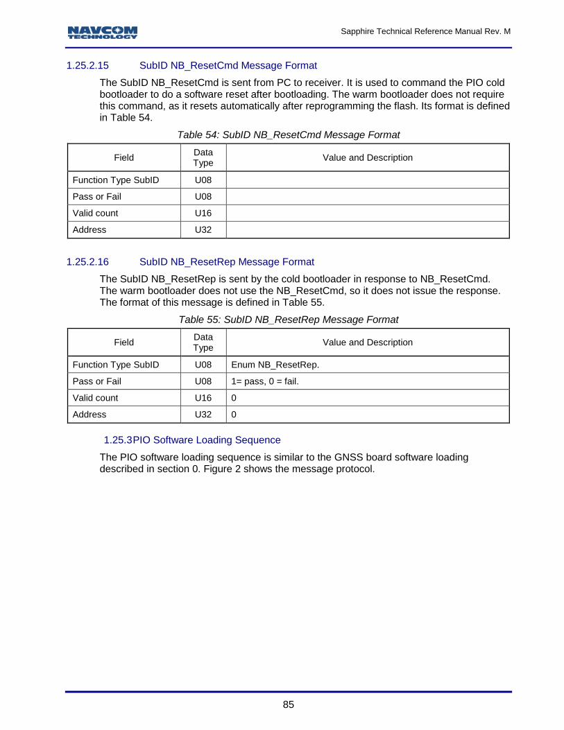
1.25.2.6 SubID NB_SetupRep Message Format ........................................................................ 80 1.25.2.7 SubID NB_LoadDataCmd Message Format ................................................................ 80 1.25.2.8 SubID NB_LoadDataRep Message Format ................................................................. 81 1.25.2.9 SubID NB_ChkCrcCmd Message Format .................................................................... 82 1.25.2.10 SubID NB_ChkCrcRep Message Format ..................................................................... 82 1.25.2.11 SubID NB_ProgCmd Message Format ........................................................................ 83 1.25.2.12 SubID NB_EraseRep Message Format ........................................................................ 83 1.25.2.13 SubID NB_WriteFRep Message Format ...................................................................... 84 1.25.2.14 SubID NB_Working Message Format .......................................................................... 84 1.25.2.15 SubID NB_ResetCmd Message Format ....................................................................... 85 1.25.2.16 SubID NB_ResetRep Message Format ........................................................................ 85
1.37.1 Reference Frame at Default State ......................................................................................... 93 1.37.2 Reference Frame at Non-Default State ................................................................................. 93 1.37.3 Special Considerations for the RTCM and RTK-Based Solutions ......................................... 93 1.37.4 Command Format and Usage ............................................................................................... 94 1.37.5 Ellipsoid Model ....................................................................................................................... 96 1.37.6 Transformation Models .......................................................................................................... 97
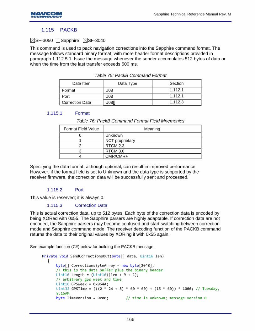
1.115.1 Format .................................................................................................................................. 166 1.115.2 Port ....................................................................................................................................... 166
Sapphire Technical Reference Manual Rev. M
6
1.115.3 Correction Data .................................................................................................................... 166 1.115.4 Theory of Operation ............................................................................................................. 168 1.115.5 Limitations and Points of Interest ......................................................................................... 168
1.198.1 USB Mode for SF-3050 Only ............................................................................................... 223 1.198.2 USB Mode for SF-3040 Only ............................................................................................... 224
1.206.1 Message General Format .................................................................................................... 235 1.206.1.1 Function Type ............................................................................................................. 236 1.206.1.2 Pass or Fail ................................................................................................................. 236 1.206.1.3 Valid Count ................................................................................................................. 236 1.206.1.4 Address ....................................................................................................................... 236 1.206.1.5 Data ............................................................................................................................ 236
1.206.2 WEBLOADB SubID Message Format ................................................................................. 237 1.206.2.1 SubID WB_PingCmd Message Format ...................................................................... 237 1.206.2.2 SubID WB_PingRep Message Format ....................................................................... 237 1.206.2.3 SubID WB_SetupCmd Message Format .................................................................... 237 1.206.2.4 SubID WB_SetupRep Message Format ..................................................................... 238 1.206.2.5 SubID WB_LoadDataCmd Message Format.............................................................. 238 1.206.2.6 SubID WB_LoadDataRep Message Format............................................................... 238 1.206.2.7 SubID WB_ ChkCrcCmd Message Format ................................................................ 239 1.206.2.8 SubID WB_ChkCrcRep Message Format .................................................................. 239 1.206.2.9 SubID WB_WriteCmd Message Format ..................................................................... 239 1.206.2.10 SubID WB_WriteRep Message Format ...................................................................... 240
2.15.1 Cooperative Tracking and StarFire CNØ ............................................................................. 255 2.15.2 StarFire Tracking Status ...................................................................................................... 255 2.15.3 StarFire Satellite ID .............................................................................................................. 256 2.15.4 Start Type and Number of Satellites Visible ........................................................................ 256 2.15.5 Position Status and Number of Satellites Tracked .............................................................. 256 2.15.6 Almanac Available and Number of Satellite Blocks in This Message ................................. 256 2.15.7 Block per PRN ..................................................................................................................... 256
2.15.7.1 PRN ............................................................................................................................ 257 2.15.7.2 Constellation Type and Channel Block Count ............................................................ 257 2.15.7.3 Satellite Azimuth and Elevation .................................................................................. 257
2.15.8 Block per Channel ................................................................................................................ 257 2.15.8.1 Channel Number ......................................................................................................... 258 2.15.8.2 Code Type and Allocation Mode ................................................................................ 258 2.15.8.3 Tracking Status and Loop Bandwidth ......................................................................... 259 2.15.8.4 C/No ............................................................................................................................ 260
2.36.1 Number of Cancel Histories ................................................................................................. 272 2.36.2 License Issue Date .............................................................................................................. 272 2.36.3 License End Date ................................................................................................................. 272 2.36.4 Date of Cancellation ............................................................................................................. 272 2.36.5 Days Left (Unused Days) ..................................................................................................... 272 2.36.6 Cancel Reason .................................................................................................................... 273 2.36.7 Cancellation Source ............................................................................................................. 273
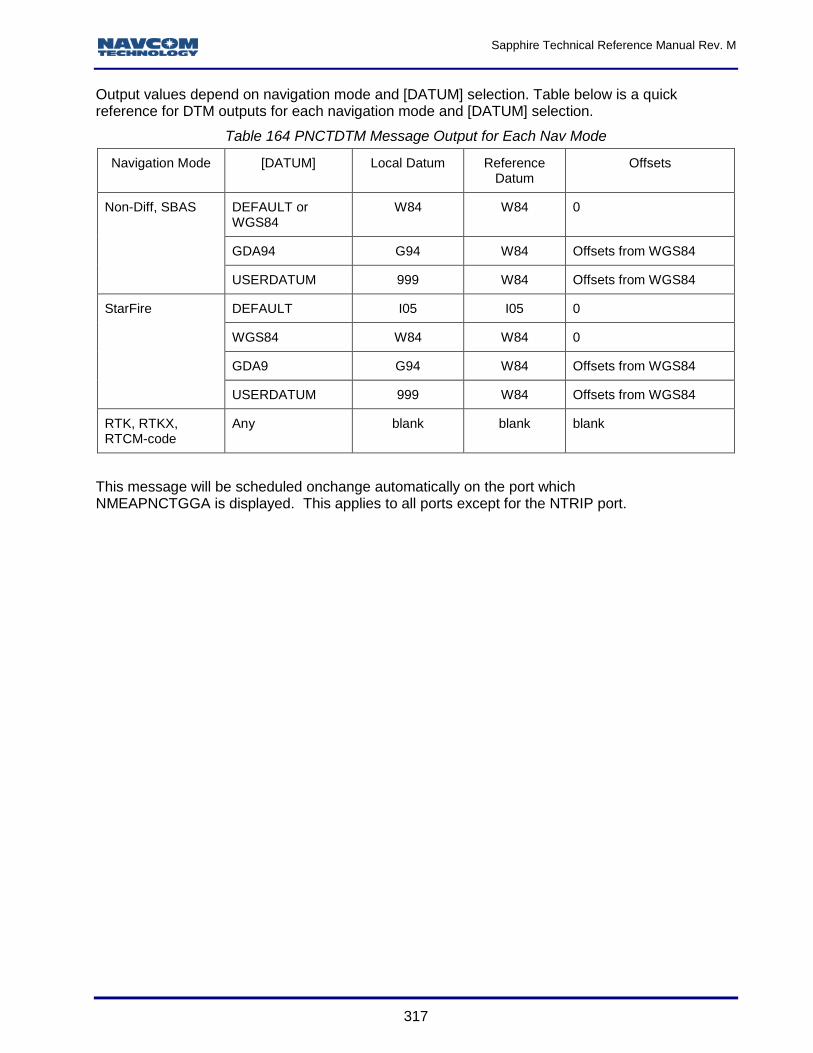
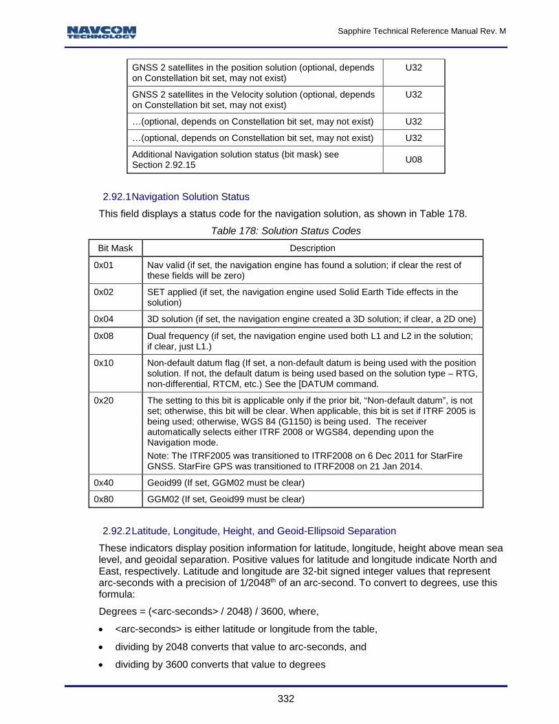
2.92.1 Navigation Solution Status ................................................................................................... 332 2.92.2 Latitude, Longitude, Height, and Geoid-Ellipsoid Separation .............................................. 332 2.92.3 Standard Deviations of Latitude, Longitude and Height ...................................................... 333 2.92.4 PDOP North, East, and Up .................................................................................................. 333 2.92.5 Velocity North, East, and Up ................................................................................................ 334 2.92.6 Number of Satellites Tracked .............................................................................................. 334 2.92.7 Navigation Solution Mode .................................................................................................... 334 2.92.8 Maximum dGPS Correction Age .......................................................................................... 336 2.92.9 dGPS Base Station ID ......................................................................................................... 336 2.92.10 Figure of Merit ...................................................................................................................... 336 2.92.11 Failure Code ........................................................................................................................ 337 2.92.12 Solid Earth Tides .................................................................................................................. 337 2.92.13 Bit Mask of GNSS Satellite Constellation Usage ................................................................. 338 2.92.14 Bit Mask of GNSS Satellites Used ....................................................................................... 338 2.92.15 Additional Navigation Solution Status .................................................................................. 338
2.111.1 Current StarFire satellite ID ................................................................................................. 357 2.111.2 Current StarFire downlink beam indicator ........................................................................... 357
Sapphire Technical Reference Manual Rev. M
11
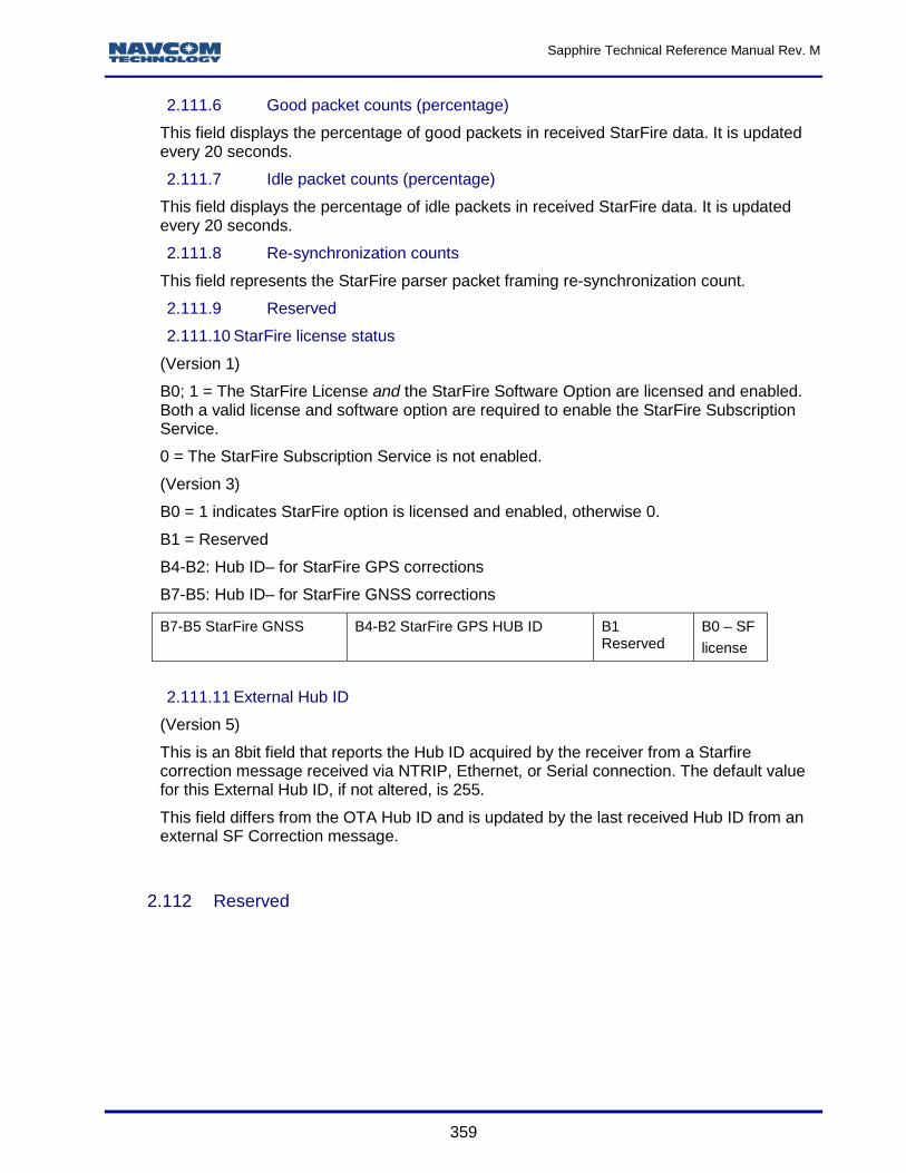
2.111.3 Current StarFire signal status .............................................................................................. 358 2.111.4 Current StarFire signal strength (Eb/NØ) ............................................................................ 358 2.111.5 Reserved .............................................................................................................................. 358 2.111.6 Good packet counts (percentage) ....................................................................................... 359 2.111.7 Idle packet counts (percentage) .......................................................................................... 359 2.111.8 Re-synchronization counts................................................................................................... 359 2.111.9 Reserved .............................................................................................................................. 359 2.111.10 StarFire license status ................................................................................................ 359 2.111.11 External Hub ID .......................................................................................................... 359
A CRC Function/Data Parsing and Decoding.................................................................. 380 Sapphire Pseudocode Message Parser .............................................................................................. 381 Sapphire Pseudocode for Coordinate Conversions ............................................................................ 384
B Software License Agreement ....................................................................................... 386 Software License Agreement for NavCom Technology, Inc. GNSS StarFire™ Receiver ................... 386
Open Source Software License Appendix ........................................................................................ 390 License Text – Module/Component: freeRTOS v4.7.2 ................................................................ 390 License Text – Module/Component: lwIP v1.2.0 ......................................................................... 396
C Logging Data to the SF-3050 Internal Memory Device ................................................ 398 Scheduling Messages .......................................................................................................................... 398 Logging Data ........................................................................................................................................ 398 Managing Datalog Files ....................................................................................................................... 401 Downloading Data from the Internal Memory to a PC ......................................................................... 403
D Uploading Unified Firmware Files Using StarUtil 3000 ............................................... 405 E Base Network RTK Configuration ................................................................................ 409
Overview .............................................................................................................................................. 409 Hardware Requirements ...................................................................................................................... 409 Hardware Configuration ....................................................................................................................... 409 Antenna Installation ............................................................................................................................. 411 Update Profile (with Ethernet Port Base Station and Radio Settings) ................................................. 411 Additional Information .......................................................................................................................... 414
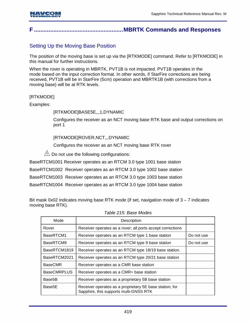
F MBRTK Commands and Responses ............................................................................ 419 Setting Up the Moving Base Position .................................................................................................. 419
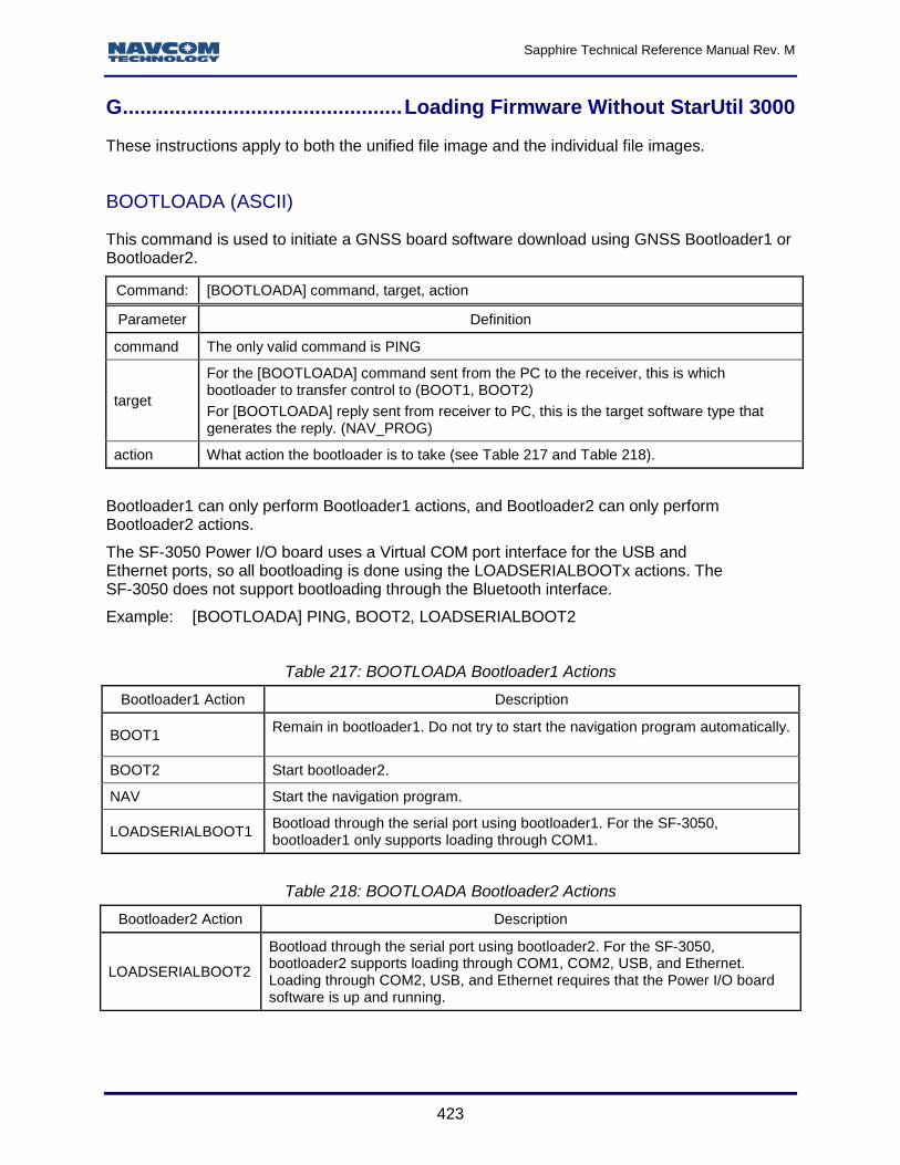
G Loading Firmware Without StarUtil 3000 ..................................................................... 423 BOOTLOADA (ASCII) .......................................................................................................................... 423 BOOTLOADB (Binary) ......................................................................................................................... 424 Message General Format .................................................................................................................... 424
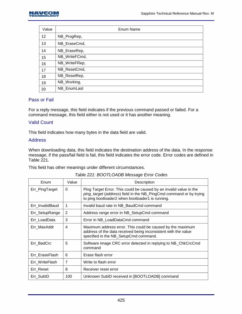
Function Type ................................................................................................................................... 424 Pass or Fail ....................................................................................................................................... 425 Valid Count ....................................................................................................................................... 425 Address............................................................................................................................................. 425 Data 426
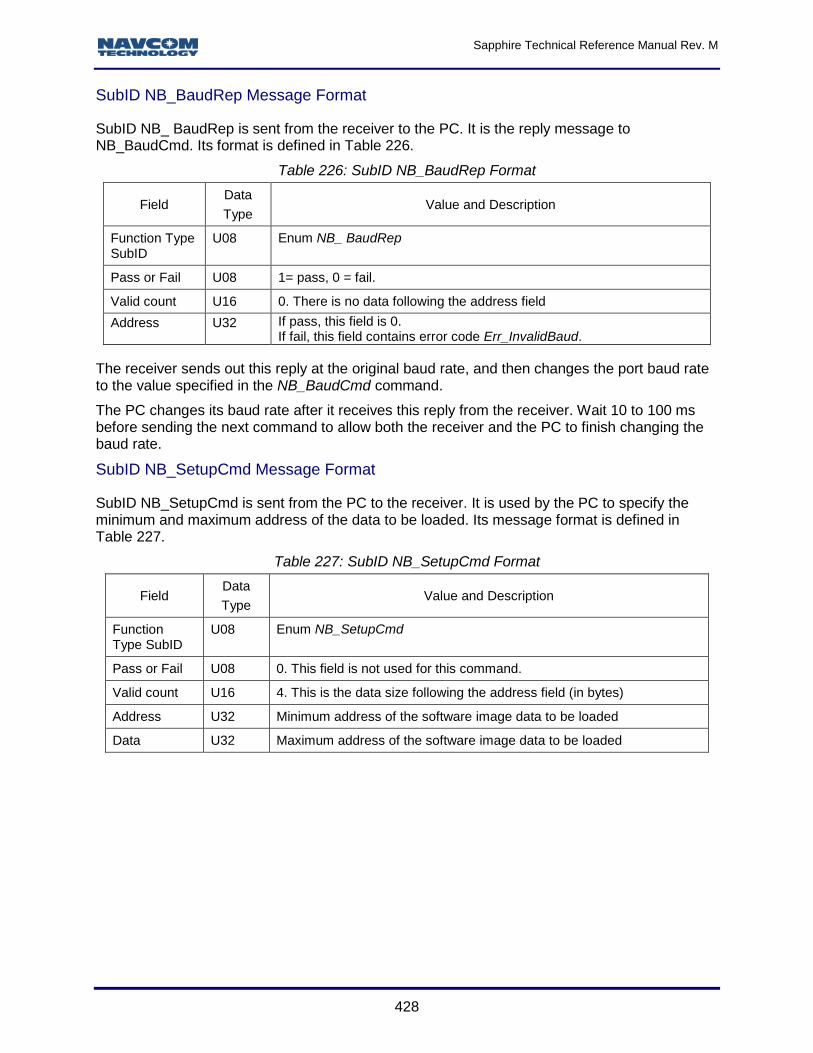
BootloadB SubID Message Format ..................................................................................................... 426 SubID NB_PingCmd Message Format ............................................................................................. 426 SubID NB_PingRep Message Format .............................................................................................. 427 SubID NB_BaudCmd Message Format ........................................................................................... 427 SubID NB_BaudRep Message Format ............................................................................................ 428 SubID NB_SetupCmd Message Format .......................................................................................... 428 SubID NB_SetupRep Message Format ........................................................................................... 429 SubID NB_LoadDataCmd Message Format .................................................................................... 429 SubID NB_LoadDataRep Message Format ..................................................................................... 430 SubID NB_ ChkCrcCmd Message Format ....................................................................................... 430 SubID NB_ChkCrcRep Message Format ......................................................................................... 431 SubID NB_ProgCmd Message Format ............................................................................................ 431 SubID NB_EraseRep Message Format ........................................................................................... 432 SubID NB_WriteFRep Message Format .......................................................................................... 432 SubID NB_Working Message Format .............................................................................................. 432 SubID NB_ResetCmd Message Format .......................................................................................... 433 SubID NB_ResetRep Message Format ........................................................................................... 433 GNSS Software Loading Sequence ................................................................................................. 434
H Connecting to the StarFire Over IP Caster .................................................................. 436 NTRIPCONFIG (ASCII) ....................................................................................................................... 436 NTRIPCLIENT (ASCII) ......................................................................................................................... 437 MPAUTOCONNECT (ASCII) ............................................................................................................... 437
I Web Server ....................................................................................................................... 438 Supported Product ............................................................................................................................... 438 Supported Browsers ............................................................................................................................ 438 Storage Location .................................................................................................................................. 438 Account information ............................................................................................................................. 438 How to Access ..................................................................................................................................... 439 How to Update ..................................................................................................................................... 439 Limitations ............................................................................................................................................ 439
Sapphire Technical Reference Manual Rev. M
13
List of Tables
Table 1: Basic Command Format Using Blanks as Delimiters ....................................................... 34 Table 2: Basic Command Format Using Commas as Delimiters ................................................... 35 Table 3: Examples of Single Argument Command Inputs and Responses .................................... 36 Table 4: Examples of Multiple Argument Command Inputs and Responses .................................. 37 Table 5: Data Type Abbreviations ................................................................................................. 38 Table 6: General Format of Sapphire Binary Output Messages .................................................... 39 Table 7: Standard Sapphire Binary Header Format ....................................................................... 39 Table 8: Time Confidence Values ................................................................................................. 40 Table 9: Simplified Sapphire Binary Header Format ...................................................................... 40 Table 10: Factory Default Output Proprietary Messages and Responses...................................... 41 Table 11: Supported Standard NMEA Output Messages .............................................................. 43 Table 12: Supported Non-Standard NMEA Output Messages ....................................................... 44 Table 13: 2D Navigation Mode Settings ........................................................................................ 47 Table 14: ALM1B Binary Command .............................................................................................. 52 Table 15: BOOTLOADA Bootloader1 Actions ............................................................................... 61 Table 16: BOOTLOADA Bootloader2 Actions ............................................................................... 61 Table 17: Software Info Structure Definition .................................................................................. 62 Software type enum defined in ...................................................................................................... 62 Descriptive text string for the product. See .................................................................................... 63 Table 18: BOOTLOADB Binary Message ...................................................................................... 63 Table 19: BOOTLOADB Message Function SubID Enum Definition ............................................. 63 Table 20: BOOTLOADB and BootloadPIOB Message Error Codes .............................................. 64 Table 21: SubID NB_PingCmd Format ......................................................................................... 66 Table 22: Software Type Enum ..................................................................................................... 66 Table 23: SubID NB_PingRep Format .......................................................................................... 67 Table 25: SubID NB_BaudRep Format ......................................................................................... 67 Table 26: SubID NB_SetupCmd Format ....................................................................................... 69 Table 27: SubID NB_SetupRep Format ........................................................................................ 69 Table 28: SubID NB_LoadDataCmd Format ................................................................................. 70 Table 29: SubID NB_ LoadDataRep Format ................................................................................. 70 Table 30: SubID NB_ChkCrcCmd Format ..................................................................................... 71 Table 31: SubID NB_ChkCrcRep Format ...................................................................................... 71 Table 32: SubID NB_ProgCmd Format ......................................................................................... 72 Table 33: SubID NB_EraseRep Format ........................................................................................ 72 Table 34: SubID NB_WriteFRep Format ....................................................................................... 72 Table 35: SubID NB_Working Format ........................................................................................... 73 Table 36: SubID NB_ResetCmd Format ....................................................................................... 73 Table 37: SubID NB_ResetRep Format ........................................................................................ 73 Table 38: BOOTLOADPIOB Binary Message ............................................................................... 76 Table 39: BOOTLOADPIOB Message Function SubID Enum Definition ....................................... 77 Table 40: SubID NB_PingCmd Format ......................................................................................... 78 Table 41: SubID NB_PingRep Format .......................................................................................... 78 Table 42: SubID NB_BaudCmd Format ........................................................................................ 79 Table 43: SubID NB_BaudRep Format ......................................................................................... 79 Table 44: SubID NB_SetupCmd Format ....................................................................................... 80 Table 45: SubID NB_SetupRep Format ........................................................................................ 80 Table 46: SubID NB_LoadDataCmd Format ................................................................................. 81 Table 47: SubID NB_LoadDataRep Format .................................................................................. 82 Table 48: SubID NB_ChkCrcCmd Message Format...................................................................... 82 Table 49: SubID NB_ChkCrcRep Message Format....................................................................... 83
Sapphire Technical Reference Manual Rev. M
14
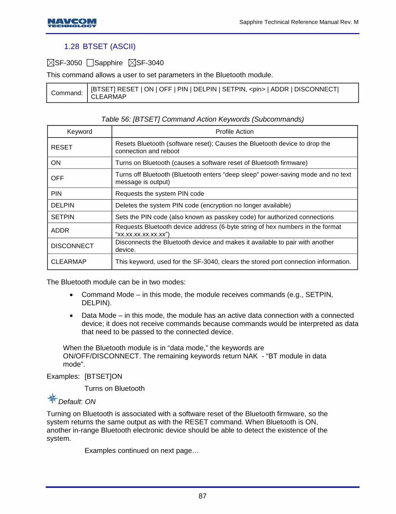
Table 50: SubID NB_ProgCmd Message Format .......................................................................... 83 Table 51: SubID NB_EraseRep Message Format ......................................................................... 84 Table 52: SubID NB_WriteFRep Message Format ........................................................................ 84 Table 53: SubID NB_Working Message Format ............................................................................ 84 Table 54: SubID NB_ResetCmd Message Format ........................................................................ 85 Table 55: SubID NB_ResetRep Message Format ......................................................................... 85 Table 56: [BTSET] Command Action Keywords (Subcommands) ................................................. 87 Table 57: Parameter List for User-Defined Datum ......................................................................... 95 Table 58: User-Defined Ellipsoid Model (with Sample Values) ...................................................... 96 Table 59: 3-Parameter Model Transformation (with Sample Values) ............................................. 97 Table 60: 7-Parameter Model Transformation (with Sample Values) ............................................. 97 Table 61: 14-Parameter Model Transformation (with Sample Values) ........................................... 98 Table 62: Dynamic Modes Mapping and Applications ................................................................. 101 Table 63: ETHVCOM Task Transport Protocol............................................................................ 110 Table 64: Default Settings for Unspecified Parameters ............................................................... 112 Table 65: GEOIDAL99 Header Format ....................................................................................... 127 Table 66: GEOIDAL99 Data Format (variable length) ................................................................. 127 Table 67: LOADBULKB Message Format ................................................................................... 135 Table 68 [LOGFILE]A: Responses .............................................................................................. 136 Table 69: Signals and/or Frequencies Keywords for NAVMEASUSE Command ......................... 152 Table 70: NTRIP Client Status Messages ................................................................................... 155 Table 71: NTRIP Client Configuration Data ................................................................................. 158 Table 72: NTRIP Server Status Messages .................................................................................. 160 Table 73: Output Command Scheduling/Timing Methods ........................................................... 163 Table 74: Output Command Port Mnemonics ............................................................................. 164 Table 75: PackB Command Format ............................................................................................ 166 Table 76: PackB Command Format Field Mnemonics ................................................................. 166 Table 77: Code-Based dGPS Modes Controlled by the PRDGPSMODE Command ................... 174 Table 78: SF_Source Controlled by the PRDGPSMODE Command (SFRTG Only) ................... 174 Table 79: [PROFILE] Command Action Keywords ...................................................................... 177 Table 80: [RTG QUICKSTART] Action Keywords ....................................................................... 186 Table 81: [RTGQUICKSTART] QuickStart Mode in Response .................................................... 187 Table 82: RTK Default Values ..................................................................................................... 188 Table 83: Base Modes ................................................................................................................ 192 Table 84: Rover Site ID Request ................................................................................................. 193 Table 85: Base Station ID ........................................................................................................... 193 Table 86: RTK Multipath Environments ....................................................................................... 196 Table 87: RTK Measurement Synchronization Mode Keywords .................................................. 198 Table 88: Signals and/or Frequencies Keywords for TRACKINGMODE Command .................... 220 Table 89: VERSION Keywords for Software Components .......................................................... 232 Table 90: WEBLOADB Binary Message...................................................................................... 235 Table 91: WEBLOADB Message Function SubID Enum Definition ............................................. 236 Table 92: SubID WB_PingCmd Format ....................................................................................... 237 Table 93: SubID WB_PingRep Format ........................................................................................ 237 Table 94: SubID WB_SetupCmd Message Format ..................................................................... 238 Table 95: SubID WB_SetupRep Format...................................................................................... 238 Table 96: SubID WB_LoadDataCmd Format .............................................................................. 238 Table 97: SubID WB_LoadDataRep Format ............................................................................... 239 Table 98: SubID WB_ChkCrcCmd Format .................................................................................. 239 Table 99: SubID WB_ChkCrcRep Message Format .................................................................... 239 Table 100: SubID WB_WriteCmd Format .................................................................................... 240 Table 101: SubID WB_WriteRep Format..................................................................................... 240 Table 102: WEBLOADB message protocol ................................................................................. 240
Sapphire Technical Reference Manual Rev. M
15
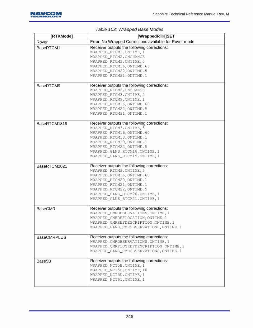
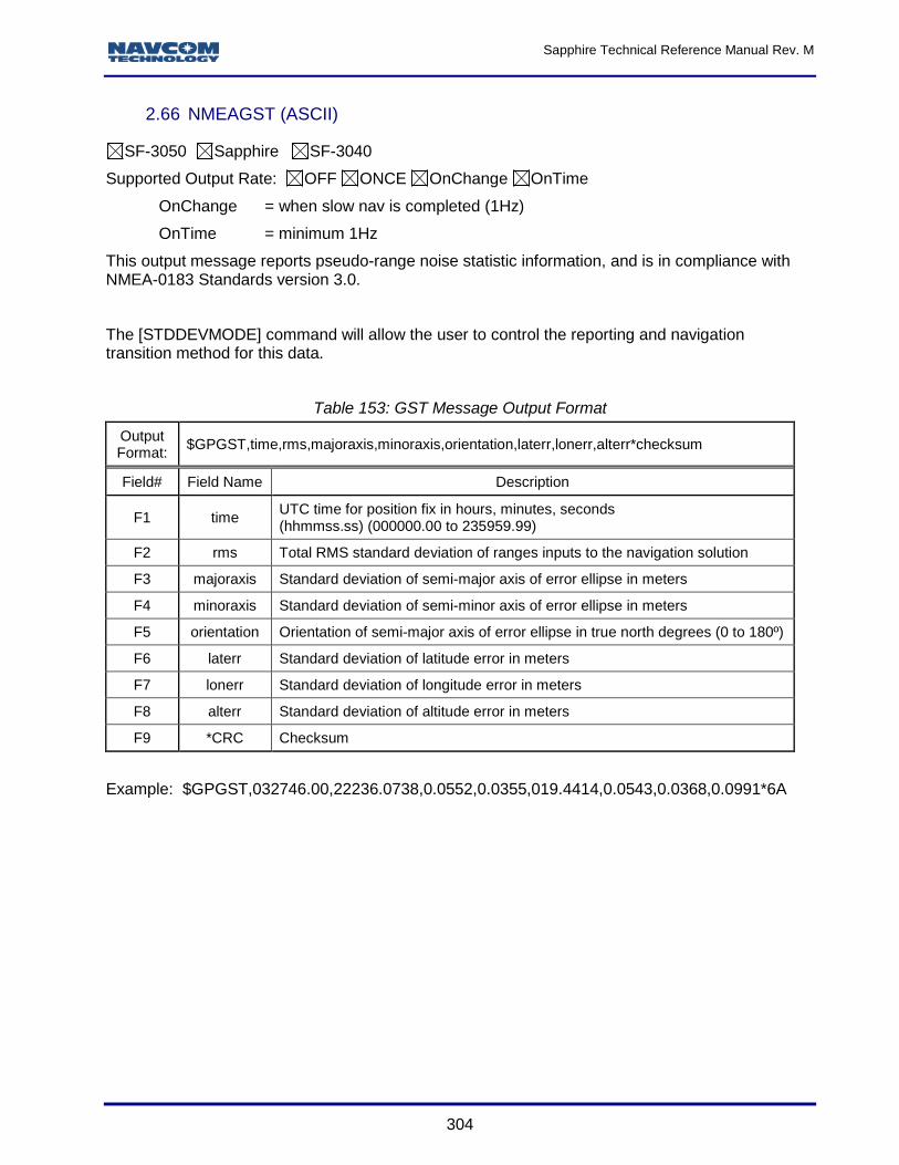
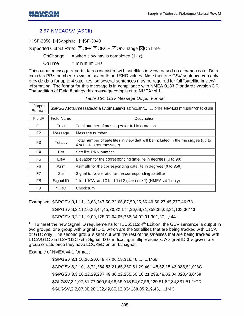
Table 103: Wrapped Base Modes ............................................................................................... 246 Table 104: Figure of Merit ........................................................................................................... 248 Table 105: ALM1B Binary Message Data .................................................................................... 249 Table 106: GPS ALM1B Binary Message Data ........................................................................... 249 Table 107: GLONASS ALM1B Binary Message Data.................................................................. 250 Table 108: SBAS ALM1B Binary Message Data ......................................................................... 251 Table 110: CHNLSTATUS1B Binary Message Data ................................................................... 255 Table 111: StarFire Tracking Status Values ................................................................................ 255 Table 112: Start Type.................................................................................................................. 256 Table 113: Position Status .......................................................................................................... 256 Table 114: CHNLSTATUS1B Satellite Block, One per PRN ........................................................ 256 Table 115: Constellation Type ..................................................................................................... 257 Table 116: CHNLSTATUS1B Blocks per Channel ...................................................................... 257 Table 117: Code Type Values ..................................................................................................... 258 Table 118: Allocation Mode ......................................................................................................... 259 Table 119: Channel Status Codes............................................................................................... 259 Table 120: Loop Bandwidth......................................................................................................... 260 Table 121: EPHEM1B Binary Message Header .......................................................................... 261 Table 122: GPS EPHEM1B Binary Message .............................................................................. 261 Table 123: GLONASS EPHEM1B Binary Message ..................................................................... 261 Table 124: Bit Mapping of GLONASS String 1 ............................................................................ 262 Table 125: SBAS EPHEM1B Binary Message ............................................................................ 262 Table 126: Figure of Merit ........................................................................................................... 264 Table 127: MBRTK1B Binary Message Body .............................................................................. 266 Table 128: MBRTK Mode ............................................................................................................ 267 Table 129: Navigation Mode ....................................................................................................... 267 Table 130: MEAS1B ................................................................................................................... 268 Table 131: Satellite Block ............................................................................................................ 268 Table 132: Signal Block .............................................................................................................. 268 Table 133: PRN Slot Number ...................................................................................................... 269 Table 134: Frequency Number .................................................................................................... 269 Table 135: Code Type ................................................................................................................. 270 Table 136: MSGCANCELCODESB ............................................................................................. 271 Table 137: MSGCANCELHISTORYB Part 1 ............................................................................... 272 Table 138: MSGCANCELHISTORYB Part 2 ............................................................................... 272 Table 139: MSGCANCELHISTORYB Cancellation Source ......................................................... 273 Table 140: MSGVERSION Keywords for Software Components ................................................ 275 Table 141: NAVCONFIGB Data Fields ........................................................................................ 276 Table 142: NEWSFALMREADY ASCII message data ................................................................ 286 Table 143: ALM Message Output Format .................................................................................... 288 Table 144 DTM Message Output Format .................................................................................... 289 Table 145 DTM Message Output for Each Nav Mode ................................................................. 289 Table 146: GBS Message Output Format ................................................................................... 291 Table 147: GFA Message Output Format .................................................................................... 293 Table 148: GGA Message Output Format ................................................................................... 296 Table 149: GLL Message Output Format .................................................................................... 298 Table 150: GNS Message Output Format ................................................................................... 299 Table 151: GRS Message Output Format ................................................................................... 301 Table 152: GSA Message Output Format ................................................................................... 303 Table 153: GST Message Output Format .................................................................................... 304 Table 154: GSV Message Output Format ................................................................................... 305 Table 155: HDT Message Output Format .................................................................................... 306 Table 156: MLA Message Output Format .................................................................................... 307
Sapphire Technical Reference Manual Rev. M
16
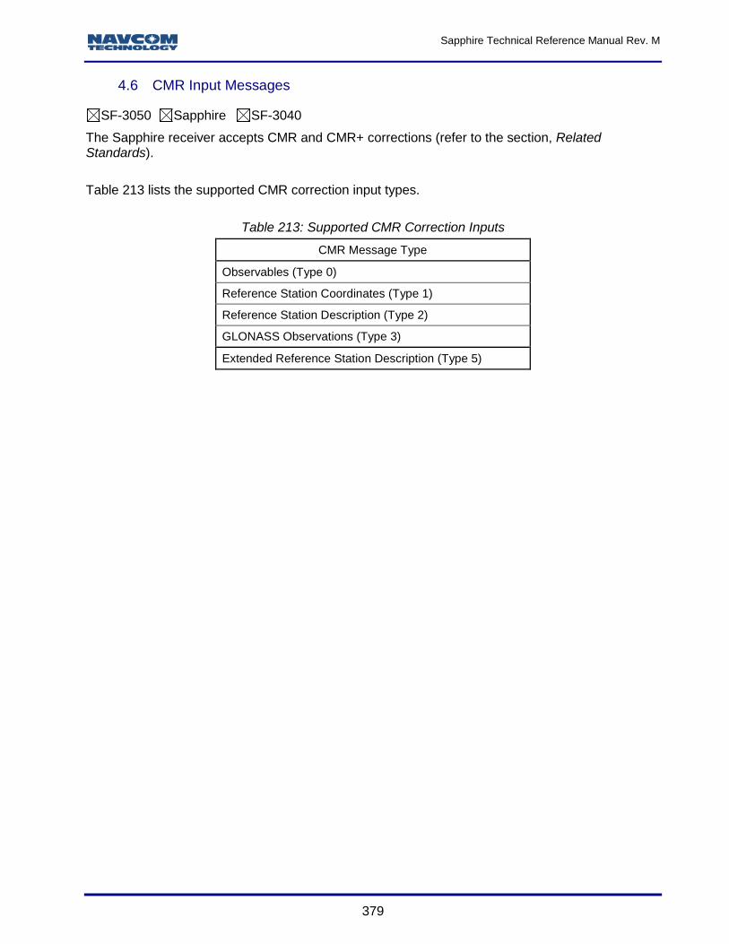
Table 157: RMC Message Output Format ................................................................................... 308 Table 158: ROT Message Output Format ................................................................................... 310 Table 159: RRE Message Output Format ................................................................................... 311 Table 160: TTM Message Output Format .................................................................................... 312 Table 161: VTG Message Output Format .................................................................................... 314 Table 162: ZDA Message Output Format .................................................................................... 315 Table 163 PNCTDTM Message Output Format ........................................................................... 316 Table 164 PNCTDTM Message Output for Each Nav Mode........................................................ 317 Table 165: PNCTGGA Message Output Format ......................................................................... 318 Table 166: Beam Selection ID ..................................................................................................... 319 Table 167: Navigation Mode ....................................................................................................... 320 Table 168: PNCTGST Message Output Format .......................................................................... 321 Table 169: MDE Message Output Format ................................................................................... 322 Table 170: NCTSET Message Output Format ............................................................................. 323 Table 171: NTRIPSTAT Message Output Examples ................................................................... 324 Table 172: PHASENAVSTATUS1B Message Body .................................................................... 325 Table 173: PHASENAVSTATUS1B Satellite Block ..................................................................... 326 Table 174: POINTRADIUSDATAB .............................................................................................. 328 Table 175: PSEUDORANGESTATSB Binary Message Data ...................................................... 329 Table 176: PVT1B Version Size Differences ............................................................................... 331 Table 177: PVT1B Binary Message ............................................................................................ 331 Table 178: Solution Status Codes ............................................................................................... 332 Table 179: Navigation Mode and Source Type Fields ................................................................. 334 Table 180: Navigation Mode ....................................................................................................... 334 Table 181: dGPS Source Type ................................................................................................... 335 Table 182: RTK Source Type ...................................................................................................... 336 Table 183: Failure Code .............................................................................................................. 337 Table 184: GNSS Satellite Constellation Usage Bit Mask ........................................................... 338 Table 185: PVT3B Message ....................................................................................................... 340 Table 186: RADIOSTAT Message .............................................................................................. 342 Table 187: RTKSTATUS1B binary message ............................................................................... 344 Table 188: RTK Search Flag Enum ............................................................................................. 345 Table 189: SATSUSEDB Binary Message Data .......................................................................... 347 Table 190: Failure Conditions ..................................................................................................... 347 Table 191: SDCARD Output Messages for the SF-3040 ............................................................. 350 Table 192: SD FLASH Output Messages for the SF-3050 .......................................................... 350 Table 193: SELFSURVEYSTATUS1A Message Output Format ................................................. 352 Table 194: SFLICENSEB Binary Message Body ......................................................................... 353 Table 195: Net Authorization ....................................................................................................... 353 Table 196: Status ........................................................................................................................ 354 Table 197: SFSATLIST1B Binary Message Data ........................................................................ 355 Table 198: SFSTATUS1B Binary Message Data ........................................................................ 357 Table 199: StarFire Beam Indicator ............................................................................................. 358 Table 200: StarFire Tracking Status ............................................................................................ 358 Table 201: STARFIREALM1B binary message data ................................................................... 360 Table 202: OTA Almanac Satellite Record .................................................................................. 361 Table 203: TXRXINFOA Message Output Format – Sapphire ..................................................... 363 Table 204: TXRXINFOA Message Output Format – SF3050 ...................................................... 364 Table 205: TXRXINFOA Message Output Format – SF-3040 ..................................................... 366 Table 206: NavCom Proprietary Correction Output Streams ....................................................... 371 Table 207: Supported NavCom Proprietary Correction Inputs ..................................................... 371 Table 208: RTCM 2.3 Correction Output Streams ....................................................................... 375 Table 209: Supported RTCM Correction Inputs ........................................................................... 376
Sapphire Technical Reference Manual 96-312007-3001 Revision M August 2016
Copyright
2016 by NavCom Technology, Inc.
All rights reserved. No part of this work or the computer program(s) described herein may be reproduced, stored, or transmitted by any means, without the expressed written consent of the copyright holders. Translation in any language is prohibited without the expressed written consent of the copyright holders.
Trademarks
‘find your way’, ‘NavCom Globe’ and ‘NAVCOM TECHNOLOGY’ logos are trademarks of NavCom Technology, Inc. StarFire™ is a registered trademark of Deere & Company. All other product and brand names are trademarks or registered trademarks of their respective holders.
User Notice
NavCom Technology, Inc. shall not be responsible for any inaccuracies, errors, or omissions in information contained herein, including, but not limited to, information obtained from third party sources, such as publications of other companies, the press, or competitive data organizations.
This publication is made available on an “as is” basis and NavCom Technology, Inc. specifically disclaims all associated warranties, whether express or implied. In no event will NavCom Technology, Inc. be liable for direct, indirect, special, incidental, or consequential damages in connection with the use of or reliance on the material contained in this publication, even if advised of the possibility of such damages. NavCom Technology, Inc. reserves the right to make improvements or changes to this publication and the products and services herein described at any time, without notice or obligation.
As used in this publication, “Solaris” refers to the project name of the SF-3050.
Software License Agreement
By powering on and using this GNSS StarFire™ Receiver, you agree to the terms and conditions of the NavCom Technology, Inc. GNSS Receiver Software License and Open Source Software Licenses. The complete terms and conditions of these software licenses may be found in the Sapphire Technical Reference Manual Appendix B.
Sapphire Technical Reference Manual Rev. M
20
Revision History
Rev M (July 2016) Initial release; specifically relates to ICD, version 7.41 (s/w ver. 3.6.9.0)
3RDPARTYRTKX Update description with regard to RTK-X
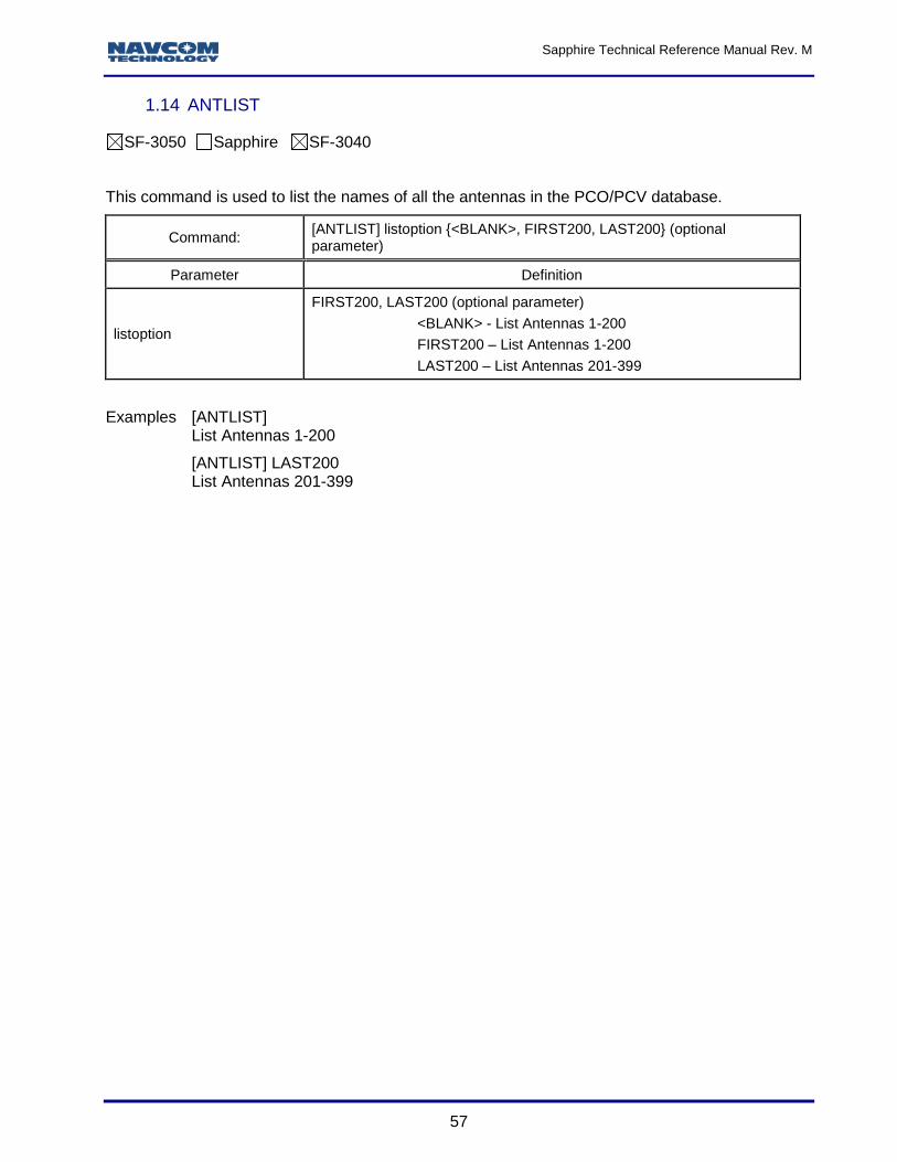
ANTLIST Added command
ANTENNAHEIGHT Added note to Phase Center Adjustment
ANTENNAINFO Updated notes
ANTREMOTE Added command
DATUM, PVT1B, & RTGQUICKSTART Update the datum of StarFire GPS from ITRF2005 to ITRF 2008.
NTRIPCONFIG Updated 30 second mountpoint and IP address for StarFire Over IP in Appendix H
STARFIREMODE Update description with regard to RTK-X
USERANTTYPE Added command
USERANTTYPEB Added command and response
WEBLOADB Update description to indicate that web pages can only be loaded via a PIOB port.
Rev L (June 2015) Initial release; specifically relates to ICD, version 7.25 (s/w ver. 3.5.8.0)
WEBUSERS Expanded command description at end
RADIO Updated Network ID keyword
GGAMODE Added keyword to Quality
ALM1B (output) Added Table 180: Navigation Mode: SBAS Health and Status Byte
NTRIPCONFIG Added NTRIP Version argument
Rev K (Aug 2014) Initial release; specifically relates to ICD, version 7.08 (s/w ver. 3.4.11.0)
3RDPARTYRTKX Added command information.
ALM1B Table 14: deleted reference to Galileo Table 105: deleted reference to Galileo Section 2.3.3 changed to “Reserved.”
CHNLSTATUS1B Deleted all references to Galileo
DEFINESFSAT Added keyword NONE
DNSOVERRIDE Added command information
EPHEM1B Table 120: deleted reference to Galileo; 2.19.3: changed to Reserved.
LOGFILE Revised file naming convention in Note 16.
NMEAGST Added note for use of [STDDEVMODE] command.
NMEAPNCTGGA Added StarFire LP mode to Table 166
NMEAPNCTGST Added note for use of [STDDEVMODE] command.
MBRTK1B Added note defining baseline velocity in Table 126.
MEAS1B Deleted all references to Galileo
MODEM Deleted command
MODEMCONFIG Deleted command.
NAVCONFIG1B Table 140: changed Galileo to Reserved.
Sapphire Technical Reference Manual Rev. M
21
Rev K (Aug 2014) Initial release; specifically relates to ICD, version 7.08 (s/w ver. 3.4.11.0)
NAVMEASUSE Added note specifying that receiver cannot operate on GLONASS signals alone.
PVT1B (Ver. 1 & Ver .2) Corrected the FOM description. Table 179: Added RTK WL note and updated NavMode for StarFire LP Table 181: Added RTCM note
RADIO Added keyword FEC for Satel modes
RAPIDRECOVERY Added default setting and note specifying that the feature is available in GPS mode only. Added FOM_LIMIT and note specifying access time limits and FOM constraints.
REFSTNPOS Added note specifying maximum position offset.
RTKDEFAULTS Table 82: Switched value of RTK navigation elevation mask with value of RTK search elevation mask.
RTKMODE Table 83: Removed reference to Galileo and COMPASS from note2. Added Type 31 and 34 to RTCM list.
NTRIPCONFIG Added AuthType Arg, Note 2 and Note 3.
NTRIPSTAT Added message information
PACKB Corrected code.
PRDGPSMODE Added SF-Source information. Updated tables 76 and 77.
PROFILE Added Note.
PVT1B Added note about StarFire transitioning from ITRF2005 to ITRF2008.
RADIOSTAT Updated warning message.
RTGQUICKSTART Added note about StarFire transitioning from ITRF2005 to ITRF2008.
RTKMODE Added optional parameter (X_ON/X_OFF) to enable or disable RTK-X.
RTKMULTIPATH Changed default to SURVEYENVIRON.
RTKTIMEOUT Corrected to indicate that the value is a float not an integer.
SBAS ALM1B Updated binary message data in Table 94.
SELFSURVEY Added command.
SELFSURVEYSTATUS1A Updated time reference in fields F6 and F7. Added height value range in field F4.
SFSTATUS1B Added External Hub information.
WRAPPEDRTK Added command.
Rev G (Sep 2012) Initial release; specifically relates to ICD, version 6.52 (s/w ver. 3.0.16.0)
CONFIGGFA Added command
DATUM Added note about StarFire transitioning from ITRF2005 to ITRF2008.
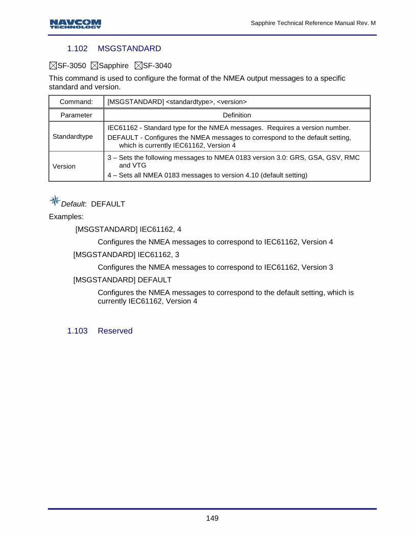
MSGSTANDARD Added command
NMEADTM Updated output rate information.
Sapphire Technical Reference Manual Rev. M
23
Rev G (Sep 2012) Initial release; specifically relates to ICD, version 6.52 (s/w ver. 3.0.16.0)
NMEAGBS Updated format to NMEA v4.1
NMEAGFA Added message
NMEAGGA Updated output rate information.
NMEAGLL Updated output rate information.
NMEAGNS Added message
NMEAGRS Updated format to NMEA v4.1
NMEAGSA Updated format to NMEA v4.1
NMEAGSV Updated format to NMEA v4.1
NMEARMC Updated format to NMEA v4.1 and output rate information.
NMEAVTG Updated format to NMEA v4.1
NMEAPCTDTM Added note about StarFire transitioning from ITRF2005 to ITRF2008. Updated output rate information.
NMEAPCTGGA Added output rate information.
NMEATTM Added message information
Rev F (Jan 2012) Initial release; specifically relates to ICD, version 6.06 (s/w ver. 3.0.9.0)
Table 7: Standard Sapphire Binary Header Format
Corrected Time Confidence and Version byte count
1PPS Corrected width and interval parameters Corrected example Added SF-3050 port support description
ANTALIGN Added User Angle capability
BASEINFOA Added output message
DATUM Added WGS84 keyword
FIXBASELINE Added formula and statement for estimating heading accuracy
GLONASSCORRECTION Changed the default setting to Off and added a note with regard use with third party base stations
LOGFILE Added [LOGFILE]A: Responses table Added more examples
LOGFILEAUTOSTART Added support for the SF-3050 internal SD flash memory
MBRTK1B Added formula and statement for estimating heading accuracy
MSGPRODUCTINFO Added a note regarding future product additions
NAVCONFIG1B Changed data type in “2D Manual Height” from U08, to R64
NAVMEASUSE Changed default setting from ALL, ON to L1,ON,L2,ON,L2C,OFF,L5,OFF,WAASEGNOS,OFF,GLONASS,ON
NMEA Messages Added an NMEA Messages Overview Added output interval data for each supported NMEA message
NMEADTM Added output message
NMEAPNCTDTM Added output message
PACKB Added update to support the SF-3050
Sapphire Technical Reference Manual Rev. M
24
Rev F (Jan 2012) Initial release; specifically relates to ICD, version 6.06 (s/w ver. 3.0.9.0)
PNCTGGA Updated Satellite Beam Selection Table
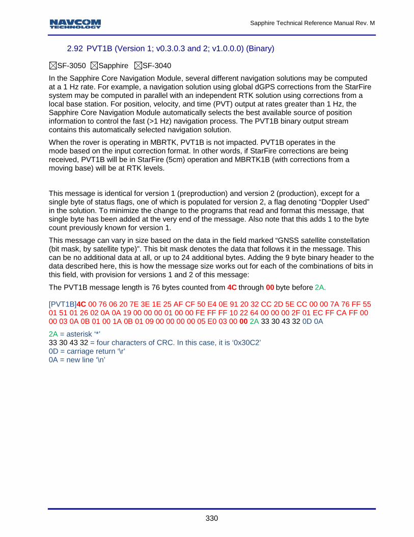
PVT1B
Added byte count example Added an example for coverting Latitude from binary to degrees Added Mean Sea Level description to paragraph 2.79.2 Added a new bit mask to Additional Navigation Solution Status for SBAS geofencing
RADIO Added channel width and protocol keywords Changed the default Network ID and Channel Bandwidth
RADIOSTAT Added channel width and protocol keywords
REFNAME Changed the number of characters Name field from a maximum of 30 to 10
ENABLERTCM2.3 Added command to allow switching between RTCM 2.2 and RTCM 2.3 data formats
RTKMODE Added note to Dynamics: The SF-3040 does not support the Dynamic keword.
RTGQUICKSTART Added statement indicating single frequency mode is not supported
SBASLIST Updated change in number of supported PRN’s
SERIALMODE Changed “This command selects either the RS232 or RS422 mode for the Sapphire COM2 serial interface” to “This command selects either the RS232 or RS422 mode for the SF-3050 COM2 serial interface.”
SFSATLIST1B Update Note 1 with regard to number of satellites supported
STARFIREALM1B Added output message
USBMODE Corrected SF-3040 keywords from “comport” or “com port” to “com_port”, and “massstorage” or “mass storage” to “mass_storage”
Rev E (June 2011) Specifically relates to ICD, v. 5.62 (s/w ver. Sapphire/SF-3050 v. 2.2.8.0; SF-3040 v. 2.1.6.0)
Message ID Revision Description
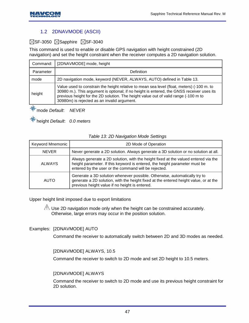
2DNAVMODE Updated the definition of ALWAYS in Table 13.
BATSTAT Updated message
BER Deleted message
CHNLSTATUS1B (Version 2)
Updated command. Table 114 was updated as follows: Changed “Constellation type and channel block count for this PRN” to “Number of channel blocks for this PRN”; added Note re definition matching Version 1, with certain exceptions
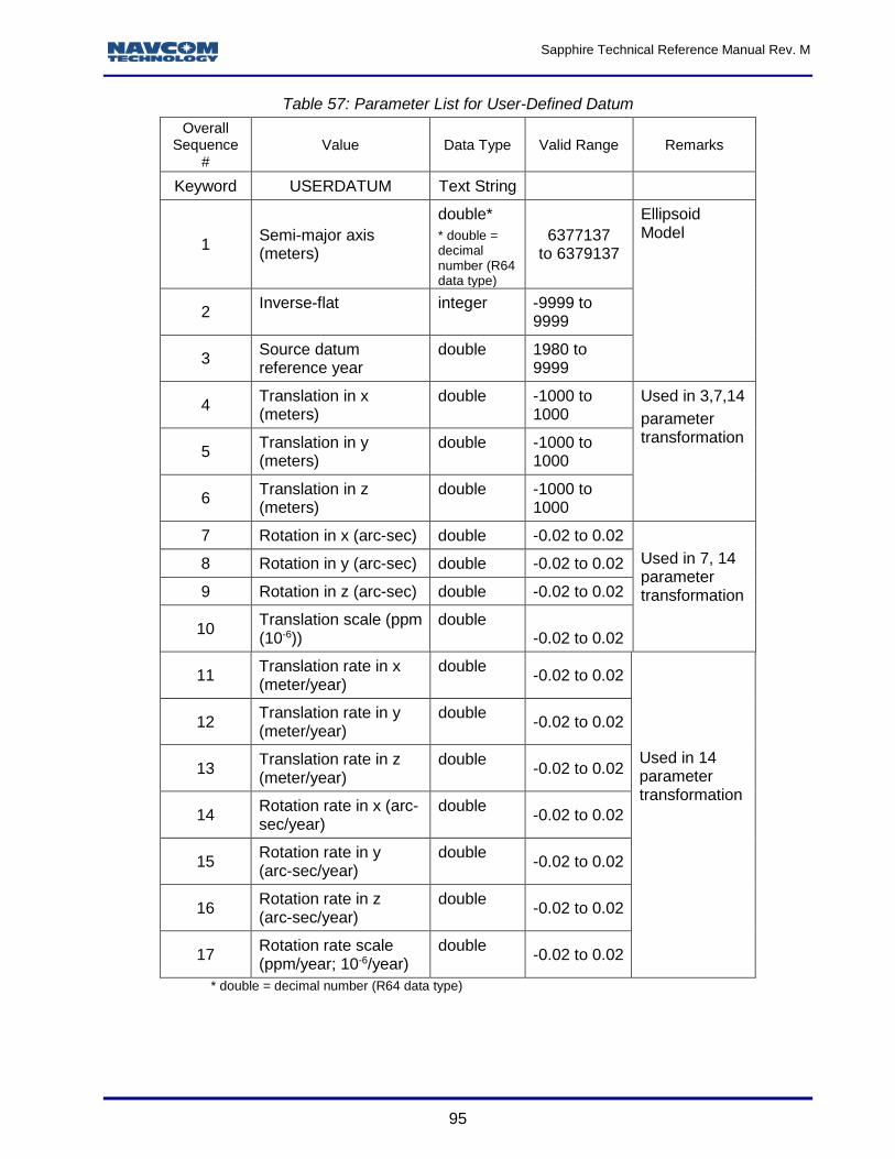
DATUM Added valid ranges to Table 1: Parameter List for User-Defined Datum Added an example to the 14-parameter list to transform from ITR-05 (StarFire) to ITRF-00 (WGS-84, G1150); updated description of the DEFAULT parameter
EVENTLATCH Deleted Port “B” from keyword definition for this command
FSFORMAT Updated command to include information about SD flash mounting progress and mounting errors
LOGFILE Added new features for the SF-3040
LOGFILEAUTOSTART Added command
L1FALLBACK Added Note re usage of this command for challenging operating environments
MBRTK1B Updated message label from “ASCII” to “Binary”
MSGPRODUCTINFO Added SF-3040 to list
MULTISATTRACK Added command
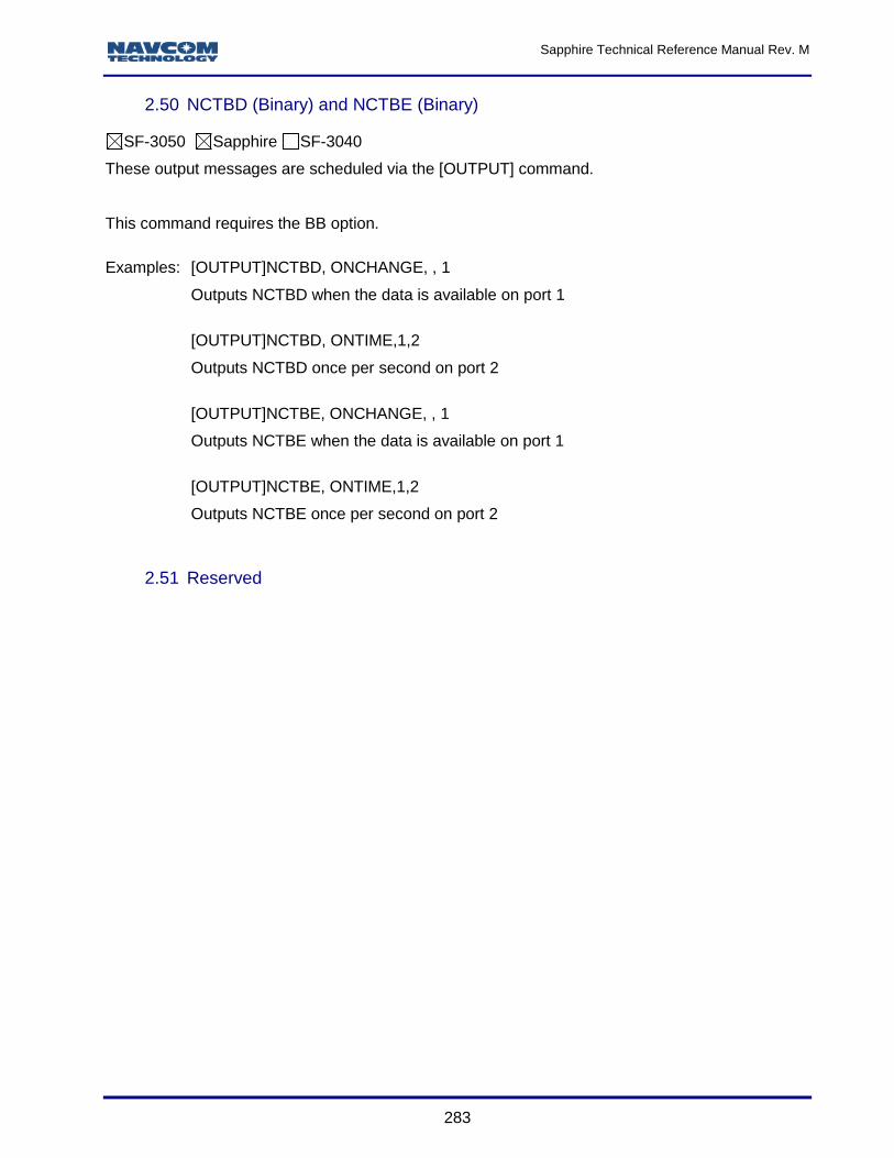
NCTBD & NCTBE Added messages
Sapphire Technical Reference Manual Rev. M
25
Rev E (June 2011) Specifically relates to ICD, v. 5.62 (s/w ver. Sapphire/SF-3050 v. 2.2.8.0; SF-3040 v. 2.1.6.0)
NMEA Messages Overview
Updated the statement “$GPxxx, describes data generated from Galileo satellites only” to…”$GAxxx, describes data generated from Galileo satellites only”
NMEAGGA Added a note regarding the GGA invalid flag operation
OUTPUT Added RADIO to the list of ports
PACKB Added command
PHASENAVSTATUS2B Added message
PNCTGGA Added four new field 14 values to support StarFire GNSS
RADIO Updated command parameters; added Network ID parameter; Default changed from ON to OFF; updated the Notes; added new examples; added data related to the SF-3040
RADIOSTAT Added message for the SF-3040
RTGQUICKSTART Corrected Height from MSL to Ellipsoidal and added Solid Earth Tide reference
RTKMODE Added the following note and renumbered all notes: “The SF-3040 does not support MBRTK mode”
SDCARD Added message
SFLICENSEB Added data item “Status” to Table 194; added Region Selection to end of command description
SFSTATUS1B
In section 2.94.1, added headings for Version 1 and Version 2 and added a description of the Current StarFire Satellite ID field for Version 2; in section 2.94.10, added heading for Version 1 and Version 3 and added a description of the StarFire License Status field for Version 3
SHUTDOWN Updated command: added new logic for ungraceful shutdown detection
STARFIREMODE Added command
TXRXINFOA Updated the description and added new tables
USBMODE Updated the Note; added warning Note about how to correctly remove the USB cable; updated warning Note about changing USB mode from COM port to other modes when the USB port is in an open state
APPENDIX E Updated the factory default profile
APPENDIX F Added Table 216, Port-Loading Requirement
Entire manual Updated numbers of commands and messages throughout document, as necessary, to maintain sequential numbering; updated all table and figure numbering; changed “This command will be used for the SF-3040” to “This command is used for the SF-3040.”
Rev D (November 2010) Specifically relates to ICD, ver. 4.84 (s/w ver. 2.0.22.0)
Message ID Revision Description
ANTENNAHEIGHT Added Default value
BATSTAT Added message
BER Added message
BTSET Added a note that the Bluetooth DISCONNECT command can only be issued from non-
Sapphire Technical Reference Manual Rev. M
26
Rev D (November 2010) Specifically relates to ICD, ver. 4.84 (s/w ver. 2.0.22.0) Bluetooth ports; added CLEARMAP keyword (slated for use in a SF-3040 )
BUZZER Added this command and added statement that it is to be used with a SF-3040.
CANCELSFLICENSE Added the following note: This command requires the receiver to be tracking GPS satellites at the moment the command is entered.
DATUM Added the following note: Only one user datum can be stored at one time. Entering a new user datum overwrites the currently stored datum
ERASEALM Added Default value
ETHVCOM Added Default values
EXTRAPBASE Changed example [EXTRAPBASE]OFF from “Sets receiver to MBRTK base” to “Turns off base-motion extrapolation mode”
FORCETALKERID Added command
INPUTSFLICENSE This command was not in alphabetical order in previous release. It has been re-sequenced: was 1.73; is: 1.75
INPUTSWOPTION This command was not in alphabetical order in previous release. It has been re-sequenced: was 1.72; is: 1.77
LOGFILE Added Note telling user what to do if this error occurs after entering the CHKDSK:A command: “Signature file not found”
MODEMCONFIG Added “This command will be used in the SF-3040…” to the description of this command.
PING Updated this command to refer user to Table 72, Output Command Mnemonics; added Default value
PVT1B Updated StarFire Source Type – “Reserved” numbers revised from 0, 1, 3-15 to 0, 1, 4-15
RADIO Added command
SBASLIST Added Default value
SETUTCOFFSET Added Default values
USBMODE Added new section 1.167.1 On-the-Go (OTG), functionality that is slated for a SF-3040
APPENDIX C Added Note telling user what to do if this error occurs after entering the CHKDSK:A command: “Signature file not found”
Entire Manual Updated numbers of commands and messages throughout document as necessary to maintain sequential numbering
Rev C (August 2010) Specifically relates to ICD, ver. 4.61 (s/w ver. 2.0.11.0)
Message ID Revision Description
ALM1B (Binary) (Command) Updated command to include “OnTime” almanac data output
ALMB1B (Binary) (Output) Updated Section reference in Table 105; added software version number for tracking
ANTALIGN Added command
Sapphire Technical Reference Manual Rev. M
27
Rev C (August 2010) Specifically relates to ICD, ver. 4.61 (s/w ver. 2.0.11.0)
Message ID Revision Description
ANTENNAINFO Added command
ARLENGTHCONSTR Added command
ASCII Output Message Organization Deleted heading
BTSET Added command
CANCELSFLICENSE Added a warning that this action cancels the subscription to StarFire signal service; users need to contact their dealer or NavCom to replace the license; added a sentence that the receiver time at the time of cancellation is used as the cancellation date
CHNLSTATUS1B
Updated command: Combined versions 1 and 2; updated Table 110, CHNLSTATUS1B Binary Message Data – data types and corresponding sections to data items;
updated Table 114, CHNLSTATUS1B Satellite Block – referenced Constellation Type section; added software version for tracking
COLDSTART Updated the command description; added the parameter DEFAULTALM; added a note re using the command with no parameters; added a note re the hard-coded almanac remaining in the receiver after the almanac in NVRAM is erased
DATUM Added command
DYNAMICS Deleted the RTKDYNAMIC and VELSMOOTH commands and combined them in this new command
ENABLEGEOFENCE Added command
EPHEM1B
Added bit mapping of GLONASS String 1 table Updated section 2.19.4 to indicate that the SBAS message type 9 can now be scheduled OnTime; added software version for tracking; added note about EPHEM1B message being a special case; added caution about not polling the receiver for messages more often than every 60 sec.; added examples
ETHCONFIG Updated this command to include the dynamic IP mode (AUTO) and the new DHCP and DNS parameters; updated the notes; updated examples
ETHVCOM
Command extensively updated: added description of IP packets; added description of four logical ports (ETH1 – ETH4); updated description of local port to range 0-65535 (from 0-65534), noting that ports 0-1023 are reserved by IANA; added Table 63, ETHVCOM Task Transport Protocol; added notes; added section on establishing an EVCOM session; added section on configuring an Ethernet connection; added/updated examples
EVENTLATCHA Added a caution that this message should only be scheduled as ONCHANGE
EXTRAPBASE Added command
FIXBASELINE Added command
FSCD Added command
FSCWD Added command
FSDELETE Added command
FSDIR Added command
FSDRIVE Added command
FSFORMAT Added command
FSMKDIR Added command
Sapphire Technical Reference Manual Rev. M
28
Rev C (August 2010) Specifically relates to ICD, ver. 4.61 (s/w ver. 2.0.11.0)
Message ID Revision Description
GLONASSCORRECTION Added command
GREETING Added command
INCLINECONSTR Added command
INPUTSFLICENSE Added input string example
INPUTSWOPTION Added input string example; changed [INPUTSWOPTION]licensestring to [INPUTSWOPTION]optionstring
LOGFILE
Command extensively updated to include USB thumb drive functionality; defined keywords: start, stop, pause, resume; added running, ready, stopped, and paused to file logging status; added warnings re avoiding file system corruption, logging dating on drive A and drive B simultaneously, and logging data at too high a data rate
MEAS1B Added software version for tracking
Message Query, pg 23 Changed [OUTPUT]VERSION,ONCE to [OUTPUT]MSGVERSION,ONCE
MBRTK1B Added message
MODEM Added command
MODEMCONFIG Added command
NAVMEASUSE Updated note about WAASEGNOS not being supported in Sapphire – added version 2.0; added warning about never using WAAS set to ON outside of the American WAAS iono grid footprint
NMEA Messages Overview, pg 30
Updated NMEA sentences naming conventions: added one that describes data generated from Galileo satellites only
NMEAALM Updated command to include ontime almanac data output; updated Table 143, Message Output Format
NMEAMLA Added note that this message can now be scheduled ontime; corrected typo “ciculing” (to “circling”) for output F7 in Table 156; added example
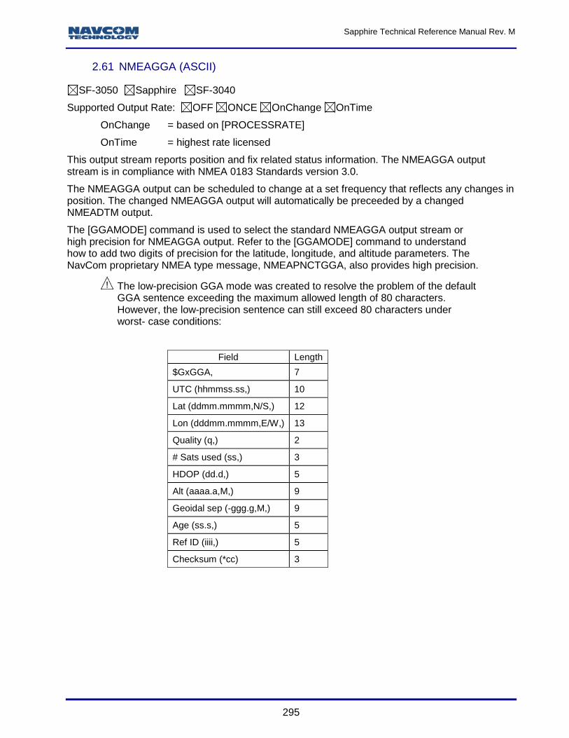
NMEAGGA Added warning re messages exceeding maximum allowable length; added a paragraph after the examples re SF-3050 output messages w/ talker ID based on current navigation mode ($GP, $GL, and $GA)
NMEAPNCTGGA
Updated message: Updated Table 166 to reflect reassignment of satellites 609 and 643. Satellite 609, which was in Net1, is now in Net2; Satellite 643, which was in Net2, is now in Net1; for ID 01, RTCM Type1, added GLONASS correction message Types 31 and 34 to Table 136
NTRIPCONFIG Added command
NTRIPCLIENT Added command
Rev C (August 2010) Specifically relates to ICD, ver. 4.61 (s/w ver. 2.0.10.0) (Continued)
Message ID Revision Description
OUTPUT
Updated command: Updated “port” identification keyword to include -1 to mean “all ports”; added warning regarding the use of -1; updated command port mnemonics table; updated the note to include statement that time intervals are limited to purchased option or are predefined based on message type; updated command mnemonics and Table 73 and Table 73; updated port number; added note about EPHEM1B message being a special case; added caution about not polling the receiver for messages more often than every 60 sec.; added examples; updated definition of “interval” parameter to include PRN numbers for EPHEM1B, RTCM3_1019, and RTCM3_1020
PASSTHRU Updated the caution statement to include user ability to turn off pass-through session;
Sapphire Technical Reference Manual Rev. M
29
added a comment that Sapphire ports F1 and F2 do not support this command; deleted Pass Through Command Port Mnemonics table.
PORT Updated Sapphire serial port numbers
POWERMODE Deleted this command – no longer supported in the software
PROCESSRATE Switched the order of this command in this manual so that it precedes the PROFILE command
PROFILE Updated to include MSAS SBAS system; switched the order of this command in this manual so that it now follows the PROCESSRATE command
PSEUDORANGESTATSB Updated message heading number from 2.83 to 2.63
PVT1B (Version 1 and Version 2)
Removed UOM from DOP description in Table 177 and paragraph 2.92.4 Corrected the comment in the source code snippet (second to last line) from "// convert S24 to R32” to "// convert S32 to R32” Updated height description in section 0. Updated Solution Status Codes Table 178 in section 0 re user-specified datum flag Updated section 2.92.4 Added bit mask 0x02 in section 2.92.15 to indicate MBRTK mode (if set, navigation mode of 3-7 indicates moving base RTK) Removed meter unit in reference to PDOP
PVT3B Added message
REFNAME Updated command default from NAVCOM REF1 to REF1
RTCM 3.0 Output Messages
Added new messages; added paragraph re RTCM3_1019 and RTCM3_1020, that they can be scheduled OnTime
RTGQUICKSTART Included a statement that best performance is achieved from a previously fully converged position and updated the Caution at end; updated Table 81
RTKMODE
Added Table 80, Base Modes, and updated the notes following the table; updated Table 84 and Table 85; added a paragraph after Table 80 about automatically scheduled messages; added dynamic_static parameters and examples; added moving base RTK examples; added Scheduling Type parameters (Auto and Manual) and an example of Manual
RTKMULTIPATH Updated command: Resolved discrepancy in default value. The default is OPENSKY.
RTKSTNID Deleted command
SBASLIST Added command
SELFSURVEY
Updated the command, adding the parameter “time” and the commands start, stop, quick-start, quick-survey, and cancel and examples of these; added note re a waiting period for the RTG readings to “settle”; added a note re synonymity of quick-survey and quick-start and how receiver generates its best results
SETL1RTK Added command
Rev C (August 2010) Specifically relates to ICD, ver. 4.61 (s/w ver. 2.0.10.0) (Continued)
Message ID Revision Description
SFLICENSEB Corrected the description from Sapphire License to StarFire license; added definitions for the issue date and start/end dates.
SFNETPRIORITY Added command
SHUTDOWN Added description of graceful and ungraceful shutdown detection logic
SIMULATORSTART Updated command: added an example
SOLIDEARTHTIDE Updated command: updated the note (correction automatically applied to single and
Sapphire Technical Reference Manual Rev. M
30
dual position solution, but not applied to non-differential and SBAS mode solutions, etc.)
STARFIREALTSAT
Updated command: “This command can be used to override selection of the default channel for StarFire” changed to “This command can be used to override selection of the default satellite ID for StarFire”; “Override the default channel selection with an alternate value” changed to “Override the default satellite ID selection with an alternate value”.
TRACKELEVMASK Updated command description to point out that satellites below this mask angle will not be tracked or used by the receiver
TRACKINGMODE Updated the notes, updated Table 88, and added a warning
TXRXINFOA Updated Table 204, the TXRXINFOA Message Output Format table: added Eth 2 – Eth 4 port fields and added Note 3 to the table
USBMODE Updated command: added two optional Device parameters: ComPort and MassStorage and examples of these; added the Default: ComPort device mode
USEPROFILE Updated warning re saving changed profile settings
WARMSTART Updated command: added an example
APPENDIX C Added Logging Data to Internal Memory
APPENDIX D Added Uploading Unified Files
APPENDIX E Added MBRTK Commands and Responses
APPENDIX F Added Network RTK
APPENDIX G Added details re uploading unified firmware without using StarUtil 3000
Rev B (October 2009) Specifically relates to ICD, version 3.37 (s/w ver. 1.0.1.5)
Message ID Revision Description
Added the Software License Agreement section to Notices, and added Appendix B Software License Agreement
BOOTLOADB Added note about PC baud rate requirements for download of GNSS firmware on COM1 and COM2 of the SF-3050 via a Serial connection
BOOTLOADPIOB Added note about PC baud rate requirements for download of PIO firmware on COM1 and COM2 of the SF-3050 via a Serial connection
EPHEM1B Added SBAS Ephemeris section
GEOIDALMODEL Added the keyword, DEFAULT, and also identified it as the default setting for this command. Added a note explaining the use of the keyword, DEFAULT. Added a section describing the GEOIDAL99 Format.
GGAMODE Added message
INPUTSFLICENSE Updated StarFire License file extension to *.lic. Added an example of the file contents.
INPUTSWOPTION Updated Software Options file extension to *.opt. Added an example of the file contents.
L1FALLBACK Added default value
MSGCANCELCODESB Updated as an encrypted message
MSGPRODUCTINFO Deleted “SF-3050B” as a product type string. Added “SF-3050” as a product type string.
NAVMEASUSE
Revised note about the disabling of L1. It is now: “L1 measurement usage is critical to the operation of the receiver. The disabling of the L1 measurement (L1,OFF) places the receiver in an “undefined configuration” which may produce unpredictable results.” Added note describing what the tracking of newer navigation satellite signals (L2C, L5, E1, and E5A) is contingent upon.
NCTBB Added message
NMEAGGA Added the high precision format to F2 (Lat), F4 (Lon), and F9 (Alt), and added an
Sapphire Technical Reference Manual Rev. M
31
example of a high precision message string. Added a reference to the GGAMODE command, and NMEAPNCTGGA.
NMEAPNCTGGA Added information about high precision string resolution of this message with references to NMEAGGA and GGAMODE. Changed PAC-W Satellite ID to 643 in the StarFire Beam Indicator table.
NVCLEAR Removed message. Executing this command renders the receiver inoperable.
OUTPUT Added this example: [OUTPUT] NONE,,,-1
PASSTHRU Added these ports to the Pass Through Command Port Mnemonics Table: Bluetooth, USB Virtual COM port, USB Thumb Drive, Ethernet Virtual COM port
RTKMODE
Added and described Base5E2 mode. Added note that the Base5B message must be used when the NCT-2100D product family (NCT-2030, RT-3010, RT-3020, SF-2040, or SF-2050) will be receiving the RTK corrections.
SFSTATUS1B (Versions 1 and 2)
Changed PAC-W Satellite ID to 643 in the StarFire Beam Indicator table. Added note to the section, “Current StarFire Signal Strength (Eb/No)”. Defined and added text to the section, “StarFire License Status”.
TRACKINGMODE
Added note describing what the tracking of newer navigation satellite signals (L2C, L5, E1, and E5A) is contingent upon. Added note on disabling tracking SBAS signals in areas where the receiver can track SBAS signals for regions other than where the receiver is located.
VELSMOOTH Added default value
Rev A (Aug 2009) Initial release; specifically relates to ICD, version 3.15 (s/w ver. 1.0.0.4)
Sapphire Technical Reference Manual Rev. M
32
Use of This Document
This User Guide is intended to be used by someone familiar with the concepts of GNSS and satellite surveying equipment.
Note indicates additional information to make better use of the product.
This symbol means Reader Be Careful. Indicates a caution, care, and/or safety situation. The user might do something that could result in equipment damage or loss of data.
This symbol means Danger. The user is in a situation that could cause bodily injury. Before starting work on any equipment, be aware of the hazards involved with electrical and RF circuitry and be familiar with standard practices for preventing accidents.
This symbol means Default. Unless otherwise set, these are the factory preset parameters.
Revisions to this User Guide can be obtained in a digital format from http://www.navcomtech.com/Support/DownloadCenter.cfm?category=manuals
Related Documents
Sapphire Integration Guide P/N 96-310028-3001
Describes the operation and use of NavCom’s Sapphire GNSS/StarFire receivers
StarUtil 3000 User Guide P/N 96-310029-3001
Describes the operation and use of NavCom’s Windows based control program (included on CD)
RINEXUtil User Guide P/N 96-310021-2101
Describes the conversion program used on NavCom proprietary output data message formats to RINEX ver 2.10 observation and navigation files (for customer programming purposes; included on CD
Technical Reference Manual P/N 96-312001-3001
Describes the control and output data message formats utilized by the NavCom legacy Starlight receivers.
NavCom Release Notes
Describes software updates for NavCom products. Current and archived Release Notes are available on the NavCom web site: http://www.navcomtech.com/Support/DownloadCenter.cfm?category=releasenotes.
NavCom Customer Support provides software updates described in the Release Notes. Submit a request for software updates via the Request Support web page.
NAVSTAR GPS Space Segment / Navigation User Interfaces Standard. ARINC Research Corporation; 2250 E. Imperial Highway; El Segundo, California 90245
RTCM-SC-104
Recommended Standards For Differential GNSS Service. Radio Technical Commission For Maritime Services; 1800 N. Kent St, Suite 1060; Arlington, Virginia 22209
CMR, CMR+
Compact Measurement Record; Trimble Navigation Limited; 935 Stewart Drive; Sunnyvale, CA 94085
NMEA-0183
National Marine Electronics Association Standard For Interfacing Marine Electronic Devices. NMEA National Office; 7 Riggs Avenue; Severna Park, Maryland 21146
QZSS
Quasi Zenith Satellite System. Japan Aerospace Exploration Agency (JAXA). 7-44-1 Jindaiji Higashi-machi, Chofu-shi, Tokyo 182-8522
Publicly Operated SBAS Signals
RTCA/DO-229D
The Radio Technical Commission for Aeronautics (RTCA) develops consensus-based recommendations regarding communications, navigation, surveillance, and air traffic management (CNS/ATM) system issues.
RTCA. 1828 L Street, NW, Suite 805, Washington, DC 20036
These organizations implement the RTCA/DO-229D standard set by RTCA:
WAAS (Wide Area Augmentation System)
U.S. Department of Transportation. Federal Aviation Administration. 800 Independence Ave, SW, Washington, DC 2059
European Space Agency. 8, 10 rue Mario-Nikis, F-75738 Paris Cedex 15, France
MSAS (MTSAT Satellite-based Augmentation System)
Japan Civil Aviation Bureau. Ministry of Transport, Kasumigaseki 2-1-3, Chiyoda-ku, Tokyo 100, Japan
GAGAN (GPS Aided Geo Augmented Navigation)
Indian Space Research Organization. Antariksh Bhavan, New Bel Road, Bangalore 560 094, India
Sapphire Technical Reference Manual Rev. M
34
Fundamental Sapphire Message Block Formats
Message Application
This document describes the formats and protocols that are applicable to all of the Sapphire receiver’s physical ports (RS-232, RS-422, USB, Ethernet) at the application layer.
Refer to these sections for basic format information:
Sapphire ASCII Input Commands
Sapphire Output Messages
Refer to these sections for detailed format information. (The commands and output streams are provided in alphabetical order according to their identifying mnemonics. Each command and output stream is provided in a table with definitions of each parameter.)
Sapphire Input Commands Detailed Formats
Sapphire Output Messages Detailed Formats
Software Ensemble
This manual specifically relates to the software ensemble version detailed in the most recent Revision History.
Message Query
Each message block may be queried by the command [OUTPUT] mnemonic, ONCE
For example, [OUTPUT] MSGVERSION, ONCE queries the receiver to provide a one-time output of the version number of the navigation firmware component.
Refer to section 1.95 OUTPUT in this manual for more information about the OUTPUT command.
Sapphire ASCII Input Commands
ASCII input commands are used to set parameters which control the operation of the Sapphire GNSS receiver. There are ASCII input commands to set navigation control parameters (DOP limits, elevation masks, etc.), to enable and disable various navigation modes, to configure the data ports, to turn on output streams, and to control numerous other receiver functions.
ASCII Message Organization
The basic format of Sapphire ASCII input commands include a command mnemonic, framed by square brackets, followed by one or more arguments, which specify the new values of the control parameters. If there is more than one argument associated with a mnemonic, the argument values may be separated by commas or by one or more blanks. Input commands are terminated by a new line sequence (<CR><LF> = carriage return + line feed).
Table 1 and Table 2 show the basic format for Sapphire input commands.
Table 1: Basic Command Format Using Blanks as Delimiters
When command responses are enabled, the Sapphire GNSS receiver issues a response to each ASCII input command. The response is output on the data port on which the command was received.
If the command is successfully parsed and accepted, the response characters are [OK] followed by the command mnemonic.
If the command does not parse successfully and is not accepted, the response characters are [??] followed by the command mnemonic, and, in some cases, an indication of which argument caused the command not to be accepted.
Refer to the section below, Examples of ASCII Input Commands and Responses.
When command responses are enabled, the receiver is in verbose mode.
ASCII Input Command Parsing Rules
These sections describe the detailed parsing rules for the ASCII input command fields.
Command Mnemonic Parsing
Command mnemonics identify which control parameter or group of control parameters are specified in the argument values. The entire command mnemonic must be enclosed in a beginning square bracket ( [ ) and an ending square bracket ( ] ). Within the brackets, the command mnemonic is not case sensitive, and any number of blanks may be used to improve legibility.
If an invalid command mnemonic is issued, the response characters will be [??] followed by the message “Unrecognized command mnemonic”.
Argument String Parsing
The argument string fields can be delimited by any number of blanks or by single commas. When null fields are needed (no argument value provided), commas must be used to indicate them. The argument string (and the entire command sentence) is terminated with a new line sequence (<CR><LF> = carriage return + line feed).
There are four types of arguments for Sapphire ASCII input commands:
1. Integers: Decimal integers containing only the characters 0 to 9 and + or –
2. Float: Floating point numbers containing only the characters 0 to 9 and + or – and, optionally, the decimal point “.”
3. Keywords: ASCII strings that must match a predefined list of options for each command These are case insensitive, but cannot contain embedded blanks. An example of a keyword argument is the parity specification for a serial port, which is either NONE, ODD, or EVEN.
4. Strings: String arguments must be enclosed in quotes (“”). Within the quotes, all ASCII characters are permissible, including commas. String arguments are intended to support user defined names and messages that require the use of some punctuation or special characters.
Sapphire Technical Reference Manual Rev. M
36
When a valid command mnemonic is received and the argument string is absent, the receiver responds with a one-time output of the stored values for the command parameters.
Optional CRC Field (*CRC)
An optional CRC field can be appended to input commands. This supports interfaces with external controllers (e.g., laptops, PDAs with wireless connectivity) with application software that computes and appends the CRC field to provide additional integrity.
The CRC field is expressed as a sequence of four hex-ASCII digits, preceded by an asterisk (*CRC). The four hex-ASCII digits represent the binary value of a 16-bit CCITT cyclic redundancy check computed by the C-language function shown in Appendix A.
Parser Pseudocode
The C-language Sapphire parser pseudocode is shown in Appendix A.
Examples of ASCII Input Commands and Responses
Table 3 shows examples of a basic single-argument command. The example uses the [NAVELEVMASK] command to set the elevation mask, in degrees, for the main, code-based navigation solution.
Table 3: Examples of Single Argument Command Inputs and Responses
Command accepted. (Note the free use of spaces and upper/lower case in the command mnemonic.)
[NAVELEVMASK] -7<CR><LF>
[??] NAVELEVMASK,argument #1 out of range<CR><LF>
Command not accepted. Problem with argument.
[NAVELEVMASK] <CR><LF> [NAVELEVMASK] 9.00<CR><LF>
No arguments specified so receiver reports current value(s).
*Command responses must be enabled to receive responses (verbose mode).
<CR><LF> = carriage return + line feed
Table 4 shows examples of a command that accepts multiple arguments. If an argument is not specified, the value is assumed to be the current set value. The command in these examples is the [PORT] command, which is used to configure the RS-232 serial ports, and the RS-422 serial port if available, of the Sapphire receiver.
[PORT] accepts up to five arguments:
1. The port identifier: An integer from 1 to 4. If this argument is not specified, the port is assumed to be the one receiving the command.
2. The baud rate (1200,2400,4800,9600,19200,38400,57600,115200)
3. The number of data bits per frame (7 or 8)
4. The number of stop bits per frame (1 or 2)
5. The parity option for each frame (NONE, ODD, EVEN)
Sapphire Technical Reference Manual Rev. M
37
Table 4: Examples of Multiple Argument Command Inputs and Responses
Input Response* Description
[PORT] 1,19200<CR><LF> [OK] PORT<CR><LF> Command accepted. Last 3 arguments left off.
[PORT] 1,19200,,,NONE<CR><LF> [OK] PORT<CR><LF>
Command accepted. Arguments 3 and 4 not specified as indicated by commas.
[PORT] 1 4800 8 1 NONE<CR><LF> [OK] PORT<CR><LF>
Command accepted. (Note use of spaces as argument delimiters.)
[PORT] 2,9600,9<CR><LF> [??] PORT,argument #3 out of range<CR><LF>
Command not accepted. Problem with third argument.
[PORT]<CR><LF> [PORT] 1,4800,8,1,NONE<CR><LF>
No arguments specified so receiver reports current value(s) for port receiving command.
[PORT] 2<CR><LF> [PORT] 2,9600,9,1,NONE<CR><LF>
Only port argument specified so receiver reports current value(s) for specified port.
* Command responses must be enabled to receive responses (verbose mode).
<CR><LF> = carriage return + line feed
Sapphire Output Messages
The Sapphire GNSS receiver supports a number of different types of output messages (data output streams). Some of these are industry standard outputs such as NMEA-0183 sentences and various RTK/dGPS correction formats (RTCM, CMR, etc.). This section, however, describes the format of specialized Sapphire output messages designed to provide access to commonly used internal receiver data (measurements, ephemeris, channel status, etc.), as well as efficient, low latency outputs of the navigation results.
Sapphire output messages are ASCII or binary. Not all binary output messages have an ASCII equivalent and vice versa.
Both ASCII and binary Sapphire output messages share these format elements in common:
Both begin with a unique, identifying ASCII mnemonic enclosed in square brackets.
The last letter of the mnemonic is the character ‘A’ for ASCII records or ‘B’ for binary records.
Both are terminated with a CRC and a new line sequence (<CR><LF> = carriage return + line feed). The CRC has a format identical to the optional CRC used for ASCII input messages, i.e., four hex-ASCII characters preceded by an asterisk (*CRC).
Binary Output Message Organization
Sapphire binary output messages use C-language structure definitions to describe the details of their formats. Table 5 lists the data type abbreviations used.
Sapphire Technical Reference Manual Rev. M
38
Table 5: Data Type Abbreviations
Data Type # of bytes C-Language Definition
U08 1 unsigned char
S08 1 signed char
Bool 1 unsigned char
U16 2 unsigned short
S16 2 signed short
U32 4 unsigned long
S32 4 signed long
R32 4 float
R64 8 double Table 6 shows the general format of Sapphire binary output messages.
Sapphire Technical Reference Manual Rev. M
39
Table 6: General Format of Sapphire Binary Output Messages [mnemonic] …… binary header …… binary message body …… *CRC<CR><LF>
Unique record identifier. ASCII ending in ‘B’ enclosed in brackets
Standard binary header described in Table 7, or simplified binary header described in Table 9.
Binary message body unique for each record identifier.
CRC followed by carriage return + line feed
The majority of the Sapphire binary messages use the standard binary message header. The simplified binary header is used only in some special cases; e.g., bootloading. The Sapphire binary messages described in this manual use the standard binary header unless otherwise indicated.
The CRC includes all of the fields in the binary header (9 bytes) and the binary message body (variable number of bytes). The CRC is expressed as a sequence of four hex-ASCII digits, preceded by an asterisk. The four hex-ASCII digits represent the binary value of a 16-bit CCITT cyclic redundancy check computed by the C-language function shown in Appendix A.
Table 7: Standard Sapphire Binary Header Format
Field # Bits Data Type Description
Length 16 U16 Number of bytes in the binary header plus the data block, i.e. data block length plus 9 bytes for the length of the binary header
GPS Week 16 U16 GPS week number
GPS time 32 U32 GPS time (milliseconds into the week)
Time Confidence 4LSB
U08
Receiver time confidence (refer to Table 8)
Version 4MSB Message version control
Sapphire Technical Reference Manual Rev. M
40
Table 8: Time Confidence Values
Code Description
0 Time is unknown
1 Time has been set from the real time clock
2 Time has been set from the serial port
3 Time has been obtained from a satellite
4 Time has been obtained from a navigation solution
5 Time has been obtained from a stable navigation solution
Table 9: Simplified Sapphire Binary Header Format
Field # Bits Data Type Description
Length 16 U16 Number of bytes in the binary header plus the data block; i.e., data block length plus 2 bytes for the length of this header
Message Updates & Software Revisions
From time to time it may be necessary for NavCom to change the format of an existing message. This is normally accomplished by appending to the existing message (which will be defined in a later version of this manual). Programmers should design software to be forward compatible by recognizing that messages may be extended and the content of the extension may be unknown to the user. In this circumstance, the message length will increase. Do not reject the data record if the message length and checksum are valid for any given record. Allow the program to ignore “undefined data” to ensure forward compatibility.
Sapphire Technical Reference Manual Rev. M
41
Factory Default Profile
Table 10: Factory Default Output Proprietary Messages and Responses
Output on Ports COM1 and USB1
Message Rate Description
ALM1B On Change Almanac
CHNLSTATUS1B On Time, 1Hz ASIC & StarFire Channel Status
EPHEM1B On Change Ephemeris
MEAS1B On Time, 1Hz Raw Measurement Data
MSGPRODUCTINFO On Time, 600 Sec Product Type, Digital Serial Number, and System Revision Number
MSGVERSION On Time, 600 Sec Firmware Identification Block
PVT1B On Time, 1Hz Position, Velocity, and Time (PVT) Solution
Output on All Ports
Message Rate Description
OK (command mnemonic) On Change Ack (“Acknowledged”). Ack indicates a successful operation.
?? (command mnemonic) On Change Nak (“Not Acknowledged”). NAK indicates a failure in executing a command.
PANICA On Change Factory Use
The messages are fully defined in sections 1 Sapphire Input Commands Detailed Formats and 2 Sapphire Output Messages Detailed Formats.
Several different navigation solutions may be computed at a 1 Hz rate. Refer to Section 2.92, PVT1B, for detailed information. The navigation rate sets the measurement rate, which must be purchased. The maximum PVT output rate is 100Hz. The maximum raw data output rate is 100Hz.
These settings indicate:
• On Change: The receiver outputs the specified message when the data changes at the highest purchased rate the system can output. For example, if the receiver has a purchased rate of 25 Hz, the messages set at On Change are output at 25 Hz.
• On Time: The receiver outputs the specified message at a rate ≤ the purchased rate. For example, if the receiver has a purchased rate of 25 Hz, a message may be set at a lower output rate, such as On Time, 0.1 (10 Hz).
In the supplied utility, StarUtil 3000, the Navigation Rate setting sets the output of the NCT Binary message PVT1B and the NMEA messages GGA, RMC and VTG, provided that those messages are set to On Change.
The NCT Binary message MEAS1B does not follow the navigation rate. To match a higher navigation rate, the user must schedule the output of MEAS1B. The rate must be a purchased navigation and raw data rate.
Sapphire Technical Reference Manual Rev. M
42
Profile Functionality
The Sapphire receiver provides for storage of up to 20 user profiles in its non-volatile memory. The command mnemonic, [PROFILE], plus the command action keyword, SAVEAS, and a user-defined “name”, saves the current configuration settings of the receiver as a user profile with the specified name. Each user profile is stored in the receiver with a name. A controller solution, such as StarUtil 3000, is used to activate a user-defined profile by its name.
Before turning off the receiver, to make the current profile available for future use, the user must save the current profile as a user profile if it is not saved already. Refer to PROFILE (ASCII) for detailed information.
A new profile sent to the receiver replaces the currently used profile, but it does not necessarily replace all the current parameter settings. The new profile replaces only those parameter settings that it specifies.
For example:
The default navigation elevation mask is 7°.
The user changes the elevation mask to 12° in a profile named “Test”. The user subsequently sends profile “RTK” to the receiver. It replaces “Test”, and changes navigation mode settings and port assignments.
But profile “RTK” does not specify a setting for the navigation elevation mask. So, the elevation mask remains at 12°, as previously set by the “Test” profile.
The command mnemonic [USEPROFILE] is used to query the name of the last profile invoked from memory or to request a different profile to be read from memory and installed as the operating configuration.
[USEPROFILE] NONE is used to reset all of the user-controlled configuration parameters to the factory default values. The receiver’s profile remains set to NONE until another profile is successfully input.
NMEA Messages Overview
This product provides support for selected sentences defined in the National Marine Electronics Association (NMEA) document 0183 “Standard for Interfacing Marine Electronic Devices”, Version 3.01, January 1, 2002 or up to v.3.0.13 of the software. Subsequent software versions support NMEA 0183, v.4.1. A software “switch” is available to return NMEA data to the former standard version. These messages are all prefixed with the string value “NMEA”, and can be viewed as a common set of sentences describing navigation data.
These NMEA sentences describe mechanics for GPS, GLONASS and WAAS satellites. To differentiate them, NMEA defines the following naming convention for satellite ids: GPS satellites are identified by their PRN numbers, which range from 1 to 32.
The numbers 33-64 are reserved for WAAS satellites. The WAAS system PRN numbers are 120-138. The offset from NMEA WAAS SV ID to WAAS PRN number is 87. A WAAS PRN number of 120 minus 87 yields the SV ID of 33. The addition of 87 to the SV ID yields the WAAS PRN number.
The numbers 65-96 are reserved for GLONASS satellites. GLONASS satellites are identified by "64 + satellite slot number". The slot numbers are 1 through 24 for the full GLONASS constellation, giving a range of 65 through 88. The numbers 89 through 96 are available if slot
Sapphire Technical Reference Manual Rev. M
43
numbers above 24 are allocated to on-orbit spares.
The NMEA sentences describe the satellite population using the following naming convention:
$GAxxx, describes data generated from Galileo satellites only
$GPxxx, describes data generated from GPS satellites only
$GLxxx, describes data generated from GLONASS satellites only
$GNxxx, describes data generated from mixed GPS, GLONASS, and Galileo satellites
The following are some common definitions that appear in NMEA sentences in particular, and in GPS frequently. Each represents a value that is accurate, but does not necessarily conform to any given mathematical range limits.
Dilution of precision is a figure of merit describing the navigation efficiency provided by the satellite geometry. This value manifests in one, two or three dimensions, and is always "the lower the better", with 1 being the ideal (best) value, and usually anything over about 20 is bad.
Geoidal height and mean sea level form virtual boundaries that define the surface of the Earth. These values grow in tables accrued by continuous surveying.
DGPS correction age is the number of seconds since the last differential correction packet arrived from a reference station. A few seconds is okay, but many seconds indicate the fix is degrading over time, and becoming less and less accurate.
A standard deviation is used to measure the error in any calculation, for example latitude or longitude. If the measurement is good, the standard deviation will be small. If not, it will be large.
The signal to noise ratio is a number that represents how "loud" the information is when compared to the ambient noise. This number is specific to the measurement.
Speed over ground is the actual speed the GNSS unit is moving over the ground. This may differ from airspeed or nautical speed due to such things as head winds or sea conditions.
Delta values for Solid Earth tides are governed by the Earth, the Moon, and other factors that also affect ocean tides. There is no specific range.
These messages are output messages only. The receiver does not process NMEA-0183 input data.
Refer to the fore-matter for the address of the headquarters of the National Marine Electronics Association (NMEA). The NMEA messages listed in this manual begin with Section 8.
Table 11: Supported Standard NMEA Output Messages NMEA
PNCTGGA Global Positioning System Fix Data, with additional station ID information
PNCTGST Scaled Pseudorange Noise Statistics
PNCTMDE Marginally Detectable Error
PNCTSET Solid Earth Tide Correction
RRE Range Residual Error
Sapphire Technical Reference Manual Rev. M
45
GPS Week Number
The GPS Week Number count began at midnight on the evening of 05 January 1980 / morning of 06 January 1980. Since that time, the count has been incremented by 1 each week, and broadcast as part of the GPS message. The GPS Week Number field in the data stream is modulo 1024. This meant that at the completion of week 1023, the GPS week number rolled over to 0 on midnight GPS Time of the evening of 21 August 1999 / morning of 22 August 1999.
GPS Time
The GPS time (seconds into the week) always starts on Sunday morning at 00:00 GMT. Each 24 hour period contains 86,400 seconds. A full week contains 604,800 seconds. Please see the table below for a breakdown of hourly / daily increments.
Reserved place holders are used throughout this manual to maintain alignment integrity with the master internal Interface Control Document maintained by NavCom Engineering.
1 Sapphire Input Commands Detailed Formats
This section provides Sapphire Input Commands in alphabetical order according to their identifying mnemonics. Each command is provided in a table with definitions of each command parameter.
1.1 1PPS (ASCII)
SF-3050 Sapphire SF-3040
This command is used to set up and control the output of the programmable PPS signal. 1PPS is available on COM1 pin 3 and Power pin 1 of the SF-3050. They are physically from the same 1PPS driver.
Polarity, width, interval, delayMS, delayNS are all optional arguments.
Examples: [1PPS] NEGATIVE,1500000,2000,50,30
Configures PPS to output a signal with a negative pulse that is 1.5ms wide, every 2 seconds, and delayed from GPS time by 50ms and 30ns
Sapphire Technical Reference Manual Rev. M
47
1.2 2DNAVMODE (ASCII)
SF-3050 Sapphire SF-3040
This command is used to enable or disable GPS navigation with height constrained (2D navigation) and set the height constraint when the receiver computes a 2D navigation solution.
Command: [2DNAVMODE] mode, height
Parameter Definition
mode 2D navigation mode, keyword (NEVER, ALWAYS, AUTO) defined in Table 13.
height
Value used to constrain the height relative to mean sea level (float, meters) (-100 m. to 30980 m.). This argument is optional; if no height is entered, the GNSS receiver uses its previous height for the 2D solution. The height value out of valid range (-100 m to 30980m) is rejected as an invalid argument.
mode Default: NEVER
height Default: 0.0 meters
Table 13: 2D Navigation Mode Settings
Keyword Mnemonic 2D Mode of Operation
NEVER Never generate a 2D solution. Always generate a 3D solution or no solution at all.
ALWAYS Always generate a 2D solution, with the height fixed at the valued entered via the height parameter. If this keyword is entered, the height parameter must be entered by the user or the command will be rejected.
AUTO Generate a 3D solution whenever possible. Otherwise, automatically try to generate a 2D solution, with the height fixed at the entered height value, or at the previous height value if no height is entered.
Upper height limit imposed due to export limitations
Use 2D navigation mode only when the height can be constrained accurately. Otherwise, large errors may occur in the position solution.
Examples: [2DNAVMODE] AUTO
Command the receiver to automatically switch between 2D and 3D modes as needed.
[2DNAVMODE] ALWAYS, 10.5
Command the receiver to switch to 2D mode and set 2D height to 10.5 meters.
[2DNAVMODE] ALWAYS
Command the receiver to switch to 2D mode and use its previous height constraint for 2D solution.
Sapphire Technical Reference Manual Rev. M
48
1.3 Reserved
1.4 Reserved
Sapphire Technical Reference Manual Rev. M
49
1.5 3RDPARTYRTKGLONASS
SF-3050 Sapphire SF-3040
For software version 3.4.2 or later.
This command turns on or off GLONASS RTK corrections usage in RTK.
This feature does not support RTCM 2.3 or RTCM 20/21.
Command: [3RDPARYRTKGLONASS] {AUTO, ON, OFF}, {Receiver Type}, {Bias}
Parameter Definition
AUTO, ON,OFF
Keyword: {AUTO,ON,OFF} AUTO: Sets the source which can change by the unit depending on the 1033 message
(or any other similar message ON: Sets the source and will not be changed by the unit regardless of the 1033
message (or any other similar message) OFF: Turns off this feature.
Receiver Type NAV, NOV, TRI, JVD, TOP, LEI, UNKNOWN, MANUAL
Bias Floating Point bias value for MANUAL mode
Default: AUTO, UNKNOWN
The abbreviations given in the Receiver Type Parameter list refer to the following third party receivers:
NAV: Navcom
NOV: Novatel
TRI: Trimble
JVD: Javad
TOP: Topcon
LEI: Leica
Behavior Summary:
Mode Source Use in L1PNav Float Fix Glonass Ambiguity OFF - NO NO
ON or AUTO UNKNOWN YES NO ON or AUTO Not UNKNOWN YES YES
Examples:
[3RDPARTYRTKGLONASS] OFF Receiver will not use GLONASS RTK corrections in RTK.
[3RDPARTYRTKGLONASS] ON, NAV Receiver will use Glonass RTK corrections from a Navcom receiver..
Sapphire Technical Reference Manual Rev. M
50
[3RDPARTYRTKGLONASS] AUTO, NOV Receiver will use Glonass RTK corrections from a Novatel receiver. If a Navcom Base transmits 1007, 1008 or 1033 message, then this will change to AUTO, NAV
[3RDPARTYRTKGLONASS] ON, MANUAL,-0.0256 Receiver will use Glonass RTK corrections with the specified bias value.
[3RDPARTYRTKGLONASS] ON, UNKNOWN Receiver will not fix Glonass Satellite Ambiguity but it will be used in L1PNAV as float.
For software version 3.2.7 or earlier:
This command is used to turn on or off 3rd party GLONASS RTK corrections usage in RTK.
Command: [3RDPARYRTKGLONASS] {ON, OFF}
Parameter Definition
ON,OFF
Keyword: {ON,OFF}
Default: OFF
Examples:
[3RDPARTYRTKGLONASS] ON Receiver will use GLONASS RTK corrections in RTK.
[3RDPARTYRTKGLONASS] OFF Receiver will not use GLONASS RTK corrections in RTK.
Sapphire Technical Reference Manual Rev. M
51
1.6 3RDPARTYRTKX
SF-3050 Sapphire SF-3040
This command enables a “FallBack” feature for 3rd party corrections in order to improve the RTK-X performance. Enabling this will turn off the Starfire Backup Engine (SF GPS) and will use that engine to calculate the bias vector for the RTK-X solution. Use only if SF GNSS is the primary positioning mode and not SF GPS. If operating on SF GPS, this feature must be turned OFF. Switching this command from ON to OFF will enable the SF GPS engine, but it will also cause it to re-converge and pull-in again.
Command: [3RDPARTYRTKX] {ON, OFF}
Parameter Definition
ON,OFF
Keyword: {ON,OFF} ON: Enables the enhanced StarFire corrections. OFF: Disables the enhanced StarFire corrections.
Default: ON
This command is linked to the RTK-X Option of the [RTKMODE] command. The user will not be able to enable this command if the RTK-X Option is set to OFF. Changing the RTK-X option to ON or OFF will change this command to ON or OFF respectively. To disable this command after enabling the RTK-X option, it must be explicitly turned OFF and the profile saved.
The user must also ensure that [STARFIREMODE] is set to BOTH and [3RDPARTYRTKGLONASS] is enabled for this command to function.
Examples:
[3RDPARTYRTKX]ON Will turn on the enhanced SF corrections. The bias vector for the 3rd party RTK base will be corrected.
[3RDPARTYRTKX]OFF Will turn off the enhanced SF corrections. The bias vector for the 3rd party RTK base will not be corrected. The unenhanced StarFire corrections must re-converge and pull-in again.
This command will be saved in the user profile. If this command is disabled, it must be saved in the profile for the changes to take effect.
1.7 Reserved
Sapphire Technical Reference Manual Rev. M
52
1.8 ALM1B (Binary)
SF-3050 Sapphire SF-3040
This is a binary command used to enter different types of almanac data manually. Refer to section 2.3, ALM1B (Version 1; v1.0.0.4) (Binary) for details on the binary format.
Table 14: ALM1B Binary Command
Data Item Data Type Section
Satellite type (-1=NONE, 0=GPS, 1=Reserved, 2=SBAS, 3=GLONASS) U08
Almanac data 2.3.1 to 2.3.3
To output [ALM1B] data, use an [OUTPUT] command to schedule the message “onchange”, “once”, or “ontime”. The command does not differentiate which type of almanac types to output. If the message is scheduled “once”, all types of almanac will be output. If it is scheduled “onchange”, only what’s updated will be output. If it is scheduled “ontime”, the minimum interval is 60 seconds.
Only GPS and GLONASS almanac data can be entered manually.
Sapphire Technical Reference Manual Rev. M
53
1.9 ANTALIGN (ASCII)
SF-3050 Sapphire SF-3040
This command is used to enter baseline installation information for the MBRTK rover.
Command: [ANTALIGN] mode, <user_angle>
Parameter Definition
Mode
LAT: Indicates two fixed antennae are laterally installed. The antennae are mounted in a ‘left-to-right’ alignment perpendicular to the center line of the vehicle. On an aircraft, this is known as the ‘axis of pitch’.
LON: Indicates two fixed antennae are longitudinally installed. The antennae are mounted in a ‘front-to-rear’ alignment along the center line of the vehicle. On an aircraft, this is known as the ‘axis of roll’.
USER: Assume longitudinally installation with additional user_angle rotation. The user_angle must be between 0-360 degrees relative to the center line of the platform
User Angle 0-360 degrees relative to the center line of the platform; referenced from the rover
Default: LON
Figure 1: Antennae Alignment – Lateral and Longitudinal
Examples: [ANTALIGN] LAT
Two fixed antennas are laterally installed.
[ANTALIGN] LON Two fixed antennas are longitudinally installed.
[ANTALIGN] USER, 352
User defined angle of 352 degrees clockwise (or 8 degrees counterclockwise)
[ANTALIGN] Status is displayed.
Sapphire Technical Reference Manual Rev. M
54
1.10 ANTENNAHEIGHT (ASCII)
SF-3050 Sapphire SF-3040
This command is used to enable or disable the antenna height adjustment.
Command: [ANTENNAHEIGHT] {mode}, antenna phase center adjustment, slant range of antenna body, radius of antenna body
Parameter Definition
Mode Keyword (ON, OFF) to enable/disable the antenna height adjustment. If this argument is empty, the receiver returns the current setting of the enable flag.
Phase Center Adjustment
Antenna height adjustment within -128 - +127 millimeters. It will be ignored if the mode is set to OFF. (Integer, millimeters); For firmware version 3.6.3 or later, this field is replaced with “Reserved”, since no other source of Antenna compensation is supported other than the Antenna Database included in the firmware. In firmware v3.6.6 and later, this value is always set to 0. Use [ANTENNAINFO] for Phase Center Adjustment.
Slant range of Antenna Body -32768 - +32767 (Integer, millimeters)
Radius of Antenna Body -32768 - +32767 (Integer, millimeters)
Default: OFF
Examples: [ANTENNAHEIGHT]ON,5.5,5000,3000 Command to set antenna height, slant range, and radius of antenna body
[ANTENNAHEIGHT]ON,0,5000,3000 Firmware v3.6.6 command to set antenna height, slant range, & antenna body radius OK [ANTENNAHEIGHT] Response from the receiver [ANTENNAHEIGHT] Request for antenna height settings [ANTENNAHEIGHT]ON,5.5,5000,3000 Response shows antenna height adjustment setting parameters [ANTENNAHEIGHT]OFF Command to disable antenna height adjustment OK [ANTENNAHEIGHT] Response from the receiver [ANTENNAHEIGHT] Request for antenna height adjustment enable status [ANTENNAHEIGHT]OFF Response shows antenna height adjustment is disabled
Sapphire Technical Reference Manual Rev. M
55
1.11 ANTENNAINFO (ASCII)
SF-3050 Sapphire SF-3040
This command allows the user to modify and retrieve antenna information, including the IGS name, serial number, and setup ID.
Command: [ANTENNAINFO] name, serial number, setup ID
Parameter Definition
Name IGS name of antenna (alphanumeric string of 0 – 32 bytes); must begin and end with quotation marks (“”); must be the exact spelling, case, and spacing of the IGS name.
Serial Number Serial number on the antenna (alphanumeric string of 0 – 32 bytes); must begin and end with quotation marks (“”)
Setup ID User-assigned antenna number of one unsigned byte (string of 0 – 255) Any combination of parameters can be made by inserting nothing between the commas.
The user may submit a string value of "" to zero-out a value.
If an antenna name that doesn’t follow the IGS convention is entered, or more or fewer than 20 characters are typed inside of the quote marks for the antenna name, or the name is not listed in the receiver antenna database, the return value of [ANTENNAINFO] is “UNKNOWN”. Type [ANTENNAINFO] after setting the parameters to check its return value after changing the antenna name to confirm the change is applied. This applies to the [ANTREMOTE] command as well.
There is one exception which applies to the user-defined antenna names. For the two user-defined antenna names, the IGS convention is not a required format; the user can enter a preferred name, as long as it has no more than 20 characters inside of the quote mark.
Using an antenna from the database will provide position at Antenna Reference Point (ARP) in NCT RTK, RTCMv3, RTKX, and StarFire navigation modes. RTCMv2, SBAS, and nondifferential navigation modes are measured in Antenna Reference Point (APC), which can adjusted using the ANTENNAHIEGHT command.
Default: SF-3050 & Sapphire is "NAV_ANT3001R NONE" SF-3040 is “NAVSF3040 NONE”
Examples: [ANTENNAINFO] "NAV_ANT3001R NONE", "7497", 48 Specifies all three parameters [ANTENNAINFO] "NAV_ANT3001R NONE" Specifies the name only ANTENNAINFO]”ANT-1”, “100300”, 48 Specifies all three parameters [ANTENNAINFO]”ANT-1” Specifies the name only [ANTENNAINFO], “100300” Specifies the serial number only
Sapphire Technical Reference Manual Rev. M
56
[ANTENNAINFO], , 48 Specifies the setup ID only [ANTENNAINFO] "NAV_ANT3001R NONE", "7497" Specifies the name and serial number [ANTENNAINFO] "NAV_ANT3001R NONE",, 48 Specifies the name and setup ID [ANTENNAINFO],"7497", 48 Response from the receiver [ANTENNAINFO] Requests the current settings OK [ANTENNAINFO] Response from the receiver
1.12 Reserved
1.13 Reserved
Sapphire Technical Reference Manual Rev. M
57
1.14 ANTLIST
SF-3050 Sapphire SF-3040
This command is used to list the names of all the antennas in the PCO/PCV database.
FIRST200, LAST200 (optional parameter) <BLANK> - List Antennas 1-200 FIRST200 – List Antennas 1-200 LAST200 – List Antennas 201-399
Examples [ANTLIST] List Antennas 1-200
[ANTLIST] LAST200 List Antennas 201-399
Sapphire Technical Reference Manual Rev. M
58
1.15 ANTREMOTE
SF-3050 Sapphire SF-3040
This command is used by a rover to set the base antenna type.
Command: [ANTREMOTE] mode {, antenna type}
Parameter Definition
mode Keyword AUTO specifies to accept RTCM message 1007, 1008, or 1033 content; or MANUAL specifies to use a user entered antenna type
antenna type 2-20 character string matching an antenna in the database. The database utilizes the IGS antenna naming convention.
Default: AUTO
If an antenna name that doesn’t follow the IGS convention is entered, or more or fewer than 20 characters are typed inside of the quote marks for the antenna name, or the name is not listed in the receiver antenna database, the return value of [ANTREMOTE] is “UNKNOWN”. Type [ANTREMOTE] after setting the parameters to check its return value after changing the antenna name to confirm the change is applied. This applies to the [ANTENNAINFO] command as well.
There is one exception which applies to the user-defined antenna names. For the two user-defined antenna names, the IGS convention is not a required format; the user can enter a preferred name, as long as it has no more than 20 characters inside of the quote mark.
Examples: [ANTREMOTE] AUTO
Uses the antenna type transferred by the the rover.
Use this command to specify whether or not the baseline length is to be used as the ambiguity constraint and pseudo measurement. To obtain a valid setting, the receiver must be in MBRTK rover mode and the fixed baseline must be set.
Command: [ARLENGTHCONSTR] ON, OFF
Parameter Definition
ON Keyword ON specifies baseline length used as constraint
OFF Keyword OFF specifies baseline length not used as constraint
Default: OFF
This constraint is fairly sensitive. Apply this constraint if you can supply a baseline length within 1 cm of accuracy. If your baseline length is not accurate within 1 cm, do not apply this constraint.
Examples: [ARLENGTHCONSTR] ON Use length as constraint
[ARLENGTHCONSTR] OFF Do not use length as constraint [ARLENGTHCONSTR] Displays length constraint status
1.17 Reserved
1.18 Reserved
1.19 Reserved
Sapphire Technical Reference Manual Rev. M
60
1.20 AUTOSCHEDULEDTM
SF-3050 Sapphire SF-3040
This command controls the automatic scheduling of the NMEADTM and NMEAPNCTDTM messages.
If this command is enabled, then:
1. NMEADTM will be scheduled automatically ONCHANGE or ONTIME whenever the user schedules NMEAGGA, NMEAGLL, NMEAGNS, or NMEARMC.
a. The NMEADTM will always change to match the fastest output rate scheduled on a specific port.
b. If either of the messages listed is scheduled ONCHANGE, then NMEADTM will be scheduled ONCHANGE.
c. If none of the above is scheduled ONCHANGE, but ONTIME instead, then NMEADTM will be scheduled ONTIME with an interval matching the fastest scheduled interval of the above messages.
2. NMEAPNCTDTM will be scheduled automatically ONCHANGE whenever the user schedules NMEAPNCTGGA.
a. The NMEAPNCTDTM will always change to match the message listed above.
3. The user will have to deschedule the DTM messages manually even if all the other related messages have been descheduled. The DTM messages will only change if any of the messages listed change to ONCHANGE or ONTIME state.
Command: [AUTOSCHEDULEDTM] ON, OFF
Parameter Definition
ON
Keyword ON: NMEADTM will be scheduled automaticall ONCHANGE whenever the user schedules either NMEAGGA, NMEAGLL, or NMEARMC. NMEAPNCTDTM will be scheduled automatically ONCHANGE whenever the user schedules NMEAPNCTGGA.
OFF Keyword OFF: NMEADTM will NOT be scheduled automatically. NMEAPNCTDTM will NOT be scheduled automatically.
Default: ON
1.21 Reserved
1.22 Reserved
Sapphire Technical Reference Manual Rev. M
61
1.23 BOOTLOADA (ASCII)
SF-3050 Sapphire SF-3040
This command is used to initiate a GNSS board software download using GNSS Bootloader1 or Bootloader2.
Command: [BOOTLOADA] command, target, action
Parameter Definition
command The only valid command is PING
target
For [BOOTLOADA] command sent from PC to receiver, this is which bootloader to transfer control to (BOOT1, BOOT2) For [BOOTLOADA] reply sent from receiver to PC, this is the target software type that generates the reply. (NAV_PROG)
action What action the bootloader is to take (see Table 15 and Table 16).
Bootloader1 can only perform Bootloader1 actions and Bootloader2 can only perform Bootloader2 actions.
The SF-3050 Power I/O board uses a Virtual COM port interface for the USB and Ethernet ports, so all bootloading is done using the LOADSERIALBOOTx actions. The SF-3050 does not support bootloading through the Bluetooth interface.
Example: [BOOTLOADA] PING, BOOT2, LOADSERIALBOOT2
Table 15: BOOTLOADA Bootloader1 Actions
Bootloader1 Action Description
BOOT1 Remain in bootloader1. Do not try to start the navigation program automatically.
BOOT2 Start bootloader2.
NAV Start the navigation program.
LOADSERIALBOOT1 Bootload through the serial port using bootloader1. For the SF-3050, bootloader1 only supports loading through COM1.
Table 16: BOOTLOADA Bootloader2 Actions
Bootloader2 Action Description
LOADSERIALBOOT2
Bootload through the serial port using bootloader2. For the SF-3050, bootloader2 supports loading through COM1, COM2, USB and Ethernet. Loading through COM2, USB and Ethernet requires that Power I/O board software is up and running.
For information on loading firmware without using StarUtil 3000, see Appendix G.
Sapphire Technical Reference Manual Rev. M
62
1.24 BOOTLOADB (Binary)
SF-3050 Sapphire SF-3040
GNSS Bootloader1 and Bootloader2 monitor the serial ports for the download of SF-3050 binary software messages. [BOOTLOADB] is the message ID for the software that is being downloaded. BOOTLOADB uses the simplified Sapphire binary header format described in Table 9.
On COM1 of the SF-3050, the maximum PC baud rate to download PIO firmware via a Serial Connection is 115200 (see Table 24).
On COM2 of the SF-3050, the required PC baud rate to download PIO firmware via a Serial Connection is 57600.
These requirements do not apply to a USB 2.0 Device or Ethernet connection.
1.24.1 Bootload Input File Format
The input file to the bootload process is the “.s19” file. This file format is generated by the software build process post-linker tool. It is the standard Motorola s-record file with special s0 record for Solaris.
The input file for the GNSS board bootload process could be one of the following: GNSS bootloader1, bootloader2, and NAV program (main application).
For Solaris (Sapphire), the input file for the PowerIO board bootload process could be one of the following: PIO bootloader and application.
1.24.1.1 Solaris (Sapphire) S0 Record Format
For Solaris, the s19 file includes multiple lines of s0 records, which contain useful information about the details of the software image, including the version, product type, product string, build data, time, etc. The information can be used with the bootloading tool to tell which program it is loading. Some older versions of the s19 file build do not implement this format of the s0 record.
The first s0 record contains the string “NCT SWINFO VER 001”. This line defines the version of the software info structure that follows. The “001” is the current version.
The second, third, and forth lines of the s0 record contain the software_info structure defined below.
Table 17: Software Info Structure Definition
Field Data Type Value and Description
CRC32 pointer U32 Address of the CRC32 of the whole software image
Major version U08 Software major version
Minor version U08 Software minor version
Build number U08 Software build number
Software type U08 Software type enum defined in Table 22
Data U08[12] ANSI C standard software build date string. Example: Mar 13 2009
Field Data Type Value and Description
Time U08[9] ANSI C standard software build time string; example: 17:17:11
Sapphire Technical Reference Manual Rev. M
63
Reserved1 U08[3] Reserved field
Product type U08
Spin number U08 Software spin number
Reserved2 U08 Reserved field
Swinfo_ver U08 Software Info structure (this structure) version
Product string U08[28] Descriptive text string for the product. See Table 22 for the list.
The data portion of those s0 records contains a maximum of 44 hex characters (representing 22 bytes of data). The total size of the software_info structure is 64 bytes, so the second and third s0 record contain 22 bytes of data, and the forth s0 record contains 20 bytes of data.
Example s0 records for bootloader1 “.s19” file: S01600004E4354205357494E464F20564552203030310050 S0190000FFF12AA0010201004A756C203234203230303900313724 S01900003A32313A33380000000003000001534F4C415249532063 S0170000474E535320424F4F54310000000000000000000028
Decoding of the first s0 record: S0 16 0000 4E4354205357494E464F2056455220303031 00 50 length | N C T S W I N F O V E R 0 0 1 | checksum address terminating null character
1.24.2 BOOTLOADB Message Body General Format
The BOOTLOADB message general format is defined in the following table:
Table 18: BOOTLOADB Binary Message
Data Item (8 Bytes + data) Data Type
Function Type SubID (enum) U08
Pass or Fail (1 = pass, 0 = fail) U08
Valid count U16
Address U32
Data U08
1.24.2.1 Function Type
Function Type provides a Function/SubID of the command. The following function type subIDs are defined as enum: (Enums ending with “Cmd” are commands sent from a PC tool to the receiver. Enums ending with “Rep” are replies sent from the receiver to a PC tool).
Table 19: BOOTLOADB Message Function SubID Enum Definition
Value Enum Name
Sapphire Technical Reference Manual Rev. M
64
1 NB_PingCmd
2 NB_PingRep,
3 NB_BaudCmd,
4 NB_BaudRep,
5 NB_SetupCmd,
6 NB_SetupRep,
7 NB_LoadDataCmd,
8 NB_LoadDataRep,
9 NB_ChkCrcCmd,
10 NB_ChkCrcRep,
11 NB_ProgCmd,
12 NB_ProgRep,
13 NB_EraseCmd,
14 NB_EraseRep,
15 NB_WriteFCmd,
16 NB_WriteFRep,
17 NB_ResetCmd,
18 NB_ResetRep,
19 NB_Working,
20 NB_EnumLast
1.24.2.2 Pass or Fail
For a reply message, this field indicates if the previous command passed or failed. For a command message, this field is either not used or has another meaning.
1.24.2.3 Valid Count
This field indicates how many bytes in the data field are valid.
1.24.2.4 Address
When downloading data, this field indicates the destination address of the data. In a response message, if the pass/fail field is fail, this field indicates the error code. BootloadB and BootloadPIOB message error codes are defined in Table 20. This field has other meanings under different circumstances.
Table 20: BOOTLOADB and BootloadPIOB Message Error Codes
Value Enum Description
0
Err_PingTarget For the BootloadB command, this means Ping Target Error. This could be caused by an invalid value in the ping_target (address) field in the NB_PingCmd command, or by trying to ping bootloader2 when bootloader1 is running. For the BootloadPIOB command, this enum is not used.
Sapphire Technical Reference Manual Rev. M
65
1 Err_InvalidBaud Invalid baud rate in NB_BaudCmd command
2 Err_SetupRange Address range error in NB_SetupCmd command
3 Err_LoadData Error in NB_LoadDataCmd command
4 Err_MaxAddr Maximum address error. This could be caused by the maximum address of
the data received being inconsistent with the value specified in NB_SetupCmd command.
5 Err_BadCrc Software image CRC error detected in replying to NB_ChkCrcCmd command
6 Err_EraseFlash Erase flash error
7 Err_WriteFlash Write to flash error
8 Err_Reset Receiver reset error
100 Err_SubID Unknown subID received in [BOOTLOADB] or [BOOTLOADPIOB] command
1.24.2.5 Data
In the NB_LoadDataCmd message, this field contains the data. It has other meanings in other SubID messages. The maximum size of this field is 2048 bytes. If loading through the Ethernet port using UDP, the maximum size should be less than about 1400 bytes.
1.24.3 BootloadB SubID Message Format
1.24.3.1 SubID NB_PingCmd Message Format
The SubID NB_PingCmd is sent from a PC to the receiver. It is used by the PC to ping the receiver bootloader software and to start the bootloading process. Its format is defined in Table 21.
Sapphire Technical Reference Manual Rev. M
66
Table 21: SubID NB_PingCmd Format
Field Data Type Value and Description
Function Type SubID U08 Enum NB_PingCmd.
Pass or Fail U08 0. This field is not used for this command
Valid count U16 0. There is no data following the address field
Address U32 Ping_Target: Ping_Target is the receiver software type that the PC program is trying to ping. The software type enum is defined in Table 22. For this command, the valid value is ST_Bootblock1 or ST_Bootblock2. For the SF-3050, Bootloader1 can be used to load any GNSS board software from COM1 except itself. Bootloader2 can be used to load any GNSS board software from both COM1 and COM2. Use bootloader2 to load software whenever possible.
Table 22: Software Type Enum
Value Enum Description Product String (in Software Info Structure)
0 ST_Boot1 GNSS board Bootloader1 software SOLARIS GNSS BOOT1
1 ST_Boot2 GNSS board Bootloader2 software SOLARIS GNSS BOOT2
2 ST_NavProg GNSS board Navigation software SOLARIS GNSS APP
3 Reserved Reserved Reserved
4 Reserved Reserved Reserved
4 ST_PioBoot PIO board bootloader (Solaris only) SOLARIS PIO BOOT
5 ST_PioApp PIO board application (Solaris only) SOLARIS PIO APP
1.24.3.2 SubID NB_PingRep Message Format
SubID NB_PingRep is sent from receiver to PC. It is the reply message for NB_PingCmd. Its format is defined in Table 23.
Sapphire Technical Reference Manual Rev. M
67
Table 23: SubID NB_PingRep Format
Field Data Type Value and Description
Function Type SubID U08 Enum NB_PingRep.
Pass or Fail U08 1= pass, 0 = fail.
Valid count U16 0. There is no data following the address field
Address U32 If pass, this field contains the enum of the software type that generates this response. If fail, this field contains error code Err_PingTarget.
1.24.3.3 SubID NB_BaudCmd Message Format
SubID NB_BaudCmd is sent from the PC to a receiver. It is used by the PC to specify an alternative Baud rate for bootloading. This message is not required if the Baud rate doesn’t need to be changed. Its message format is defined in Table 24.
For the SF-3050, if GNSS software bootloading port is USB or Ethernet, this command has no effect and should not be sent. Also, due to hardware architecture design, if GNSS software bootloading port is COM2, this command is not sent. Table 24: SubID NB_BaudCmd Format
Field Data Type Value and Description
Function Type SubID U08 Enum NB_BaudCmd
Pass or Fail U08 0. This field is not used for this command
Valid count U16 0. There is no data following the address field
Address U32 The Baud rate the PC commands the receiver to change to. The supported Baud rates are: 1200, 2400, 4800, 9600, 19200, 38400, 57600, 115200
1.24.3.4 SubID NB_BaudRep Message Format
SubID NB_ BaudRep is sent from receiver to PC. It is the reply message for NB_BaudCmd. Its format is defined in Table 25.
Table 25: SubID NB_BaudRep Format
Field Data Type Value and Description
Function Type SubID U08 Enum NB_ BaudRep.
Pass or Fail U08 1= pass, 0 = fail.
Valid count U16 0. There is no data following the address field
Address U32 If pass, this field is 0. If fail, this field contains error code Err_InvalidBaud.
The receiver sends out this reply at the original baud rate, and then changes the port baud rate to the value specified in the NB_BaudCmd command.
Sapphire Technical Reference Manual Rev. M
68
The PC changes its baud rate after it receives this reply from the receiver. Wait 10 to 100 ms before sending the next command from the PC to allow both the receiver and the PC to finish changing the baud rate.
1.24.3.5 SubID NB_SetupCmd Message Format
SubID NB_SetupCmd is sent from the PC to the receiver. It is used by the PC to specify the minimum and maximum address of the data to be loaded. Its message format is defined in Table 26.
Sapphire Technical Reference Manual Rev. M
69
Table 26: SubID NB_SetupCmd Format
Field Data Type Value and Description
Function Type SubID U08 Enum NB_SetupCmd.
Pass or Fail U08 0. This field is not used for this command
Valid count U16 4. This is the data size following the address field (in bytes)
Address U32 Minimum address of the software image data to be loaded
Data U32 Maximum address of the software image data to be loaded
1.24.3.6 SubID NB_SetupRep Message Format
SubID NB_SetupRep is sent from receiver to PC. It is the reply message for NB_ SetupCmd. Its format is defined in Table 27.
Table 27: SubID NB_SetupRep Format
Field Data Type Value and Description
Function Type SubID U08 Enum NB_ SetupRep.
Pass or Fail U08 1= pass, 0 = fail.
Valid count U16 0. There is no data following the address field
Address U32 If pass, this field is 0. If fail, this field contains error code Err_SetupRange.
1.24.3.7 SubID NB_LoadDataCmd Message Format
SubID NB_LoadDataCmd is used for sending software image data from PC to receiver. Its format is defined in Table 28.
Sapphire Technical Reference Manual Rev. M
70
Table 28: SubID NB_LoadDataCmd Format
Field Data Type Value and Description
Function Type SubID U08 Enum NB_LoadDataCmd.
Pass or Fail U08
For Solaris GNSS bootloader1, this field is not used. Value should be 0. For Solaris GNSS bootloader2, this field is the data frame number between 1 and 255 (inclusive). For each sub-sequent data messages, this number shall increment by 1. When it reaches 255, next message shall have value 1 again. The Solaris bootloader2 uses a sliding window so that each data message does not need to be acknowledged before sending the next. However, the window should be kept reasonably small with high speed ports like Ethernet and Bluetooth. The recommended window size is 3. If Solaris bootloader2 receives a data message out of order, it won’t ack or nak, which should cause a timeout for PC to resend the old data frame. Current version of Solaris bootloader1 doesn’t implement this mechanism. (This field is not used in Solaris bootloader1)
Valid count U16 Number of data in the data field (in bytes)
Address U32 Destination address of the first data byte in data field
Data U08[] Array of software image data
1.24.3.8 SubID NB_LoadDataRep Message Format
SubID NB_LoadDataRep is sent from receiver to PC. It is the reply message for NB_LoadDataCmd. Its format is defined in Table 29.
Table 29: SubID NB_ LoadDataRep Format
Field Data Type Value and Description
Function Type SubID U08 Enum NB_LoadDataRep.
Pass or Fail U08 1= pass, 0 = fail.
Valid count U16 This is the length for the data field (in bytes). 0 for SF-3050 bootloader1. 1 for SF-3050 bootloader2.
Address U32 If pass, this field is the address in the received command. If fail, this field contains error code Err_LoadData.
Data U08 This field only exists for SF-3050 bootloader2. It contains the data frame number of the received command that generates this reply.
1.24.3.9 SubID NB_ChkCrcCmd Message Format
SubID NB_ ChkCrcCmd is sent from PC to receiver. It is used to tell the receiver that the data loading process is complete. After receiving this command, the receiver starts comparing the maximum address of the received data with the value in the NB_SetupCmd message, and computing the CRC of all the received data. Its format is defined in Table 30.
Sapphire Technical Reference Manual Rev. M
71
Table 30: SubID NB_ChkCrcCmd Format
Field Data Type Value and Description
Function Type SubID U08 Enum NB_ChkCrcCmd.
Pass or Fail U08 This field is not used for this command. Value should be 0.
Valid count U16 0
Address U32 0
1.24.3.10 SubID NB_ChkCrcRep Message Format
SubID NB_ChkCrcRep is sent from receiver to PC. It is the reply message for NB_ChkCrcCmd. Its format is defined in Table 31.
Table 31: SubID NB_ChkCrcRep Format
Field Data Type Value and Description
Function Type SubID U08 Enum NB_ChkCrcRep.
Pass or Fail U08 1= pass, 0 = fail.
Valid count U16 This is the length for the data field (in bytes). 4 if fail due to CRC error 0 otherwise
Address U32
If pass, the value is 0. If fail due to maximum address not equal to the value in NB_SetupCmd, the value is error code Err_MaxAddr. If fail due to CRC error, the value is error code Err_BadCrc.
Data U32 This field only exists if fail due to CRC error. Its value is the computed CRC32 of the data image.
1.24.3.11 SubID NB_ProgCmd Message Format
SubID NB_ ProgCmd is sent from PC to receiver. It is used to tell the receiver to start programming the new data into Flash. After receiving this command, the receiver starts erasing the Flash and writing the new data into Flash. Its format is defined in Table 32.
Sapphire Technical Reference Manual Rev. M
72
Table 32: SubID NB_ProgCmd Format
Field Data Type Value and Description
Function Type SubID U08 Enum NB_ProgCmd.
Pass or Fail U08 This field is not used for this command. Value should be 0.
Valid count U16 0
Address U32 0
1.24.3.12 SubID NB_EraseRep Message Format
SubID NB_EraseRep is sent from receiver to PC. It is one of the reply messages for NB_ProgCmd. The receiver sends out this message after it erases Flash, which typically takes 1 to 3 seconds. Its format is defined in Table 33.
Table 33: SubID NB_EraseRep Format
Field Data Type Value and Description
Function Type SubID U08 Enum NB_EraseRep.
Pass or Fail U08 1= pass, 0 = fail.
Valid count U16 0
Address U32 If pass, value is 0. If fail, value is error code Err_EraseFlash.
1.24.3.13 SubID NB_WriteFRep Message Format
SubID NB_WriteFRep is sent from receiver to PC. It is one of the reply messages for NB_ProgCmd. The receiver sends out this message after it writes new data to Flash, which can take up to 20 seconds, depending on program size. Its format is defined in Table 34.
Table 34: SubID NB_WriteFRep Format
Field Data Type Value and Description
Function Type SubID U08 Enum NB_WriteFRep.
Pass or Fail U08 1= pass, 0 = fail.
Valid count U16 0
Address U32 If pass, value is 0. If fail, value is error code Err_WriteFlash.
Sapphire Technical Reference Manual Rev. M
73
1.24.3.14 SubID NB_Working Message Format
SubID NB_Working is sent from receiver to PC. It is one of the reply messages for NB_ProgCmd. The receiver sends out this message at approximately 1 Hz rate when the receiver is erasing Flash or writing data to Flash. It is used to keep the PC from timing out because erasing and writing data to flash might take up to 20 seconds. Its format is defined in Table 35.
Table 35: SubID NB_Working Format
Field Data Type Value and Description
Function Type SubID U08 Enum NB_Working.
Pass or Fail U08 1
Valid count U16 0
Address U32 0
1.24.3.15 SubID NB_ResetCmd Message Format
SubID NB_ResetCmd is sent from PC to receiver. It is used to tell the GNSS board software to do a software reset after bootloading. After reset, the GNSS board runs navigation software if it exists; otherwise, it stays in bootloader1. Its format is defined in Table 36.
Table 36: SubID NB_ResetCmd Format
Field Data Type Value and Description
Function Type SubID U08 Enum NB_ResetCmd.
Pass or Fail U08 0
Valid count U16 0
Address U32 0
1.24.3.16 SubID NB_ResetRep Message Format
SubID NB_ResetRep is sent from receiver to PC. It is the reply message for NB_ResetCmd. Its format is defined in Table 37.
2. If GNSS board navigation software is running, it decodes the command and replies with “[BOOTLOADA]PING, NAV_PROG”. Then it runs bootloader1 or bootloader2. Bootloader1 and bootloader2 always run at the default baud rate 57600. If GNSS board bootloader1 or bootloader2 is already running, the reply is NAK.
PC Receiver Bootloader1 or Bootloader2
3. If received [BOOTLOADA] reply, go to step 4. If received NAK, continue to send the [BOOTLOADA] command 2 more times, then go to step 4.
4. Change PC baud rate to 57600 and send out “[BOOTLOADB]NB_PingCmd” command. The ping_target field should be consistent with the one in [BOOTLOADA] command. “[BOOTLOADB]NB_PingCmd” may need to be sent out multiple times before a reply can be received due to the receiver transitioning between navigation software and bootloader1 or bootloader2. Sending this command at 5 Hz rate until a reply is received is recommended.
Normally when bootloader1 starts, there is a 0.5 seconds window in which it listens to the bootload command. Sending this command at 5 Hz rate will improve the chance of bootloader1 catching the command within the window and help receiver recovery in some cases.
5. Bootloader1 or bootloader2 runs, receives the command and replies with [BOOTLOADB]NB_PingRep”.
Table continued on next page…
Sapphire Technical Reference Manual Rev. M
75
PC Receiver Navigation Software
6. If the PC wants to change the baud rate, send “[BOOTLOADB]NB_BaudCmd”; otherwise, go to step 11.
This command is not sent under certain circumstances. Refer to section 1.21.3.3 for more details.
7. Send “[BOOTLOADB]NB_BaudRep” and start to change receiver baud rate.
8. After receiving “[BOOTLOADB]NB_BaudRep”, change PC baud rate.
9. Send “[BOOTLOADB]NB_PingCmd” again at new baud rate. This message may need to be sent multiple times before a reply is received, due to lack of synchronization between PC and receiver because of the changing baud rate. Sending this command at 1 Hz rate until a reply is received is recommended.
10. Reply with “[BOOTLOADB]NB_PingRep”
11. Send “[BOOTLOADB]NB_SetupCmd” 12. Reply with “[BOOTLOADB]NB_SetupRep”
13. Send “[BOOTLOADB]NB_LoadDataCmd” 14. Reply with “[BOOTLOADB]NB_LoadDataRep”
15. Repeat step 13 and 14 until all the software image data are sent
16. Send “[BOOTLOADB]NB_ChkCrcCmd” 17. Reply with “[BOOTLOADB]NB_ChkCrcRep”
18. Send “[BOOTLOADB]NB_ProgCmd” 19. Start to erase Flash and send out “[BOOTLOADB]NB_Working” at 1 Hz rate
20. Reply with “[BOOTLOADB]NB_EraseRep” when finished erasing the Flash
21. Start to write new data to Flash and send “[BOOTLOADB]NB_Working” at 1 Hz rate
22. Reply with “[BOOTLOADB]NB_WriteFRep” when finished writing new data to the Flash
23. Send “[BOOTLOADB]NB_ResetCmd” 24. Reply with “[BOOTLOADB]NB_ResetRep” and do GNSS software reset.
For information on loading firmware without using StarUtil 3000, see Appendix G.
Sapphire Technical Reference Manual Rev. M
76
1.25 BOOTLOADPIOB (Binary)
SF-3050 Sapphire SF-3040
This command is used for downloading new Solaris (Sapphire) Power I/O cold bootloader and application software images. The binary software message that is downloading has the message ID [BOOTLOADPIOB]. BOOTLOADPIOB uses the simplified Sapphire binary header format described in Table 9.
The input file format of the PIO bootload process is the same as described in section 1.21.1.
Because of architectural differences between the PIO cold bootloader and warm bootloader, the commands and responses used near the end of the bootloading sequence are slightly different for the two bootloaders.
On COM2 of the SF-3050, the maximum PC baud rate to download PIO firmware via a Serial Connection is 115200 (see Table 42).
On COM1 of the SF-3050, the required PC baud rate to download PIO firmware via a Serial Connection is 57600.
These requirements do not apply to a USB 2.0 Device or Ethernet connection.
1.25.1 Message General Format
The message general format is defined in Table 38.
Table 38: BOOTLOADPIOB Binary Message
Data Item (8 Bytes + data) Data Type
Function Type SubID (enum) U08
Pass or Fail (1 = pass, 0 = fail) U08
Valid count U16
Address U32
Data U08[]
1.25.1.1 Function Type
Function Type provides a Function/SubID of the command. The following function type subIDs are defined as enum: (Enums ending with “Cmd” are commands sent from the PC to the receiver. Enums ending with “Rep” are replies sent from the receiver to the PC).
Sapphire Technical Reference Manual Rev. M
77
Table 39: BOOTLOADPIOB Message Function SubID Enum Definition
Value Enum Name
1 NB_PingCmd
2 NB_PingRep,
3 NB_BaudCmd,
4 NB_BaudRep,
5 NB_SetupCmd,
6 NB_SetupRep,
7 NB_LoadDataCmd,
8 NB_LoadDataRep,
9 NB_ChkCrcCmd,
10 NB_ChkCrcRep,
11 NB_ProgCmd,
12 NB_ProgRep,
13 NB_EraseCmd,
14 NB_EraseRep,
15 NB_WriteFCmd,
16 NB_WriteFRep,
17 NB_ResetCmd,
18 NB_ResetRep,
19 NB_Working,
20 NB_EnumLast 1.25.1.2 Pass or Fail
For reply messages, this field indicates if the previous command passed or failed. For command messages, this field is either not used, or has another meaning (defined below).
1.25.1.3 Valid Count
This field indicates how many bytes in the data field are valid.
1.25.1.4 Address
When downloading data, this field indicates the destination address of the data. In response messages, if the pass/fail field is fail, this field indicates the error code. Error codes are defined in Table 20. This field has other meanings under different circumstances (defined below).
Sapphire Technical Reference Manual Rev. M
78
1.25.1.5 Data
In NB_LoadDataCmd message, this field contains the data. It has other meanings in other subID messages. The maximum size of this field is 2048 bytes. If loading through the Ethernet port using UDP, the maximum size should be less than 1400 bytes.
1.25.2 BOOTLOADPIOB SubID Message Format
1.25.2.1 SubID NB_PingCmd Message Format
SubID NB_PingCmd is sent from PC to receiver. It is used by the PC to ping the receiver bootloader software and to start the bootloading process. Its format is defined in Table 40.
Table 40: SubID NB_PingCmd Format
Field Data Type Value and Description
Function Type SubID U08 Enum NB_PingCmd
Pass or Fail U08 0. This field is not used for this command
Valid count U16 0. There is no data following the address field
Address U32 0. The PIO does not require a “Target Type” in this message as does the GNSS firmware.
1.25.2.2 SubID NB_PingRep Message Format
SubID NB_PingRep is sent from receiver to PC. It is the reply message for NB_PingCmd. Its primary function in the PIO firmware load process is to verify the PIO is ready to begin the download process. Its format is defined in Table 41.
Table 41: SubID NB_PingRep Format
Field Data Type Value and Description
Function Type SubID U08 Enum NB_PingRep.
Pass or Fail U08 1. Always set to “PASS” by PIO firmware.
Valid count U16 0. There is no data following the address field
Address U32 Same as the address field in the NB_PingCmd msg.
1.25.2.3 SubID NB_BaudCmd Message Format
SubID NB_BaudCmd is sent from PC to receiver. It is used by the PC to specify an alternative baud rate for bootloading. This message is not required if the baud rate doesn’t need to be changed (see Table 42 for the message format).
If the PIO software bootloading port is USB or Ethernet, this command has no effect and is not sent. Also, due to hardware architecture design, if the PIO software bootloading port is COM1, this command is not sent.
Sapphire Technical Reference Manual Rev. M
79
Table 42: SubID NB_BaudCmd Format
Field Data Type Value and Description
Function Type SubID U08 Enum NB_BaudCmd.
Pass or Fail U08 0. This field is not used for this command
Valid count U16 0. There is no data following the address field
Address U32 Baud rate PC commands the receiver to change to. The supported baud rates are: 1200, 2400, 4800, 9600, 19200, 38400, 57600, 115200
1.25.2.4 SubID NB_BaudRep Message Format
SubID NB_ BaudRep is sent from receiver to PC. It is the reply message for NB_BaudCmd. Its format is defined in Table 43.
Table 43: SubID NB_BaudRep Format
Field Data Type Value and Description
Function Type SubID U08 Enum NB_ BaudRep.
Pass or Fail U08 1= pass, 0 = fail.
Valid count U16 0. There is no data following the address field
Address U32 If pass, this field is 0. If fail, this field contains error code Err_InvalidBaud.
The receiver sends out this reply at the original baud rate, then changes the port baud rate to the value specified in the NB_BaudCmd command.
The PC changes its baud rate after it receives this reply from the receiver. It is recommended that the PC wait for 10 to100ms before it sends the next command to allow both the receiver and PC to finish changing baud rate.
1.25.2.5 SubID NB_SetupCmd Message Format
SubID NB_SetupCmd is sent from PC to receiver. It is used for the PC to specify the minimum and maximum address of the data to be loaded (see Table 44 for the message format).
Sapphire Technical Reference Manual Rev. M
80
Table 44: SubID NB_SetupCmd Format
Field Data Type Value and Description
Function Type SubID U08 Enum NB_SetupCmd.
Pass or Fail U08 0. This field is not used for this command
Valid count U16 4. This is the data size following the address field (in bytes)
Address U32 Minimum address of the software image data to be loaded
Data U32 Maximum address of the software image data to be loaded 1.25.2.6 SubID NB_SetupRep Message Format
SubID NB_SetupRep is sent from receiver to PC. It is the reply message for NB_ SetupCmd. Its format is defined in Table 45.
Table 45: SubID NB_SetupRep Format
Field Data Type Value and Description
Function Type SubID U08 Enum NB_ SetupRep.
Pass or Fail U08 1= pass, 0 = fail.
Valid count U16 0. There is no data following the address field
Address U32 If pass, this field is 0. If fail, this field contains error code Err_SetupRange.
1.25.2.7 SubID NB_LoadDataCmd Message Format
SubID NB_LoadDataCmd is used for sending software image data from PC to receiver. Its format is defined in Table 46.
Sapphire Technical Reference Manual Rev. M
81
Table 46: SubID NB_LoadDataCmd Format
Field Data Type Value and Description
Function Type SubID U08 Enum NB_LoadDataCmd
Pass or Fail U08
This field is the data frame number between 1 and 255 (inclusive). For each subsequent data message, this number increments by 1. When it reaches 255, the next message has the value 1. The Solaris uses a sliding window so that each data message does not need to be acknowledged before sending the next. However, the window should be kept reasonably small with high speed ports like Ethernet and Bluetooth. The recommended window size is 3. If Solaris (Sapphire) receives a data message out of order, it won’t Ack or Nak, which should cause a timeout on the PC to resend the 1st data frame in the current window.
Valid count U16 Number of data bytes in the data field
Address U32 Destination address of the first data byte in data field
Data U08[] Software image data
1.25.2.8 SubID NB_LoadDataRep Message Format
SubID NB_LoadDataRep is sent from receiver to PC. It is the reply message for NB_LoadDataCmd. Its format is defined in Table 47.
Sapphire Technical Reference Manual Rev. M
82
Table 47: SubID NB_LoadDataRep Format
Field Data Type Value and Description
Function Type SubID U08 Enum NB_LoadDataRep
Pass or Fail U08 1= pass, 0 = fail
Valid count U16 This is the length for the data field (in bytes). 0 for the Solaris (Sapphire) bootloader1. 1 for Solaris (Sapphire) bootloader2.
Address U32 If pass, this field is the address in the received command. If fail, this field contains error code Err_LoadData.
Data U08[] This field contains the data frame number of the received command that generates this reply.
1.25.2.9 SubID NB_ChkCrcCmd Message Format
SubID NB_ ChkCrcCmd is sent from PC to receiver. It is used to tell the receiver that the data loading process is complete. After receiving this command, the receiver starts comparing the maximum address of the received data with the value in the NB_SetupCmd message, and computing the CRC of all the received data. Its format is defined in Table 48.
Table 48: SubID NB_ChkCrcCmd Message Format
Field Data Type Value and Description
Function Type SubID U08 Enum NB_ChkCrcCmd.
Pass or Fail U08 This field is not used for this command. The value should be 0.
Valid count U16 0
Address U32 0
1.25.2.10 SubID NB_ChkCrcRep Message Format
SubID NB_ChkCrcRep is sent from receiver to PC. It is the reply message for NB_ChkCrcCmd. Its format is defined in Table 49.
Sapphire Technical Reference Manual Rev. M
83
Table 49: SubID NB_ChkCrcRep Message Format
Field Data Type Value and Description
Function Type SubID U08 Enum NB_ChkCrcRep.
Pass or Fail U08 1= pass, 0 = fail.
Valid count U16 This is the length for the data field (in bytes). 4 if fail due to CRC error 0 otherwise
Address U32
If pass, value is 0. If fail due to maximum address not equal to the value in NB_SetupCmd, value is error code Err_MaxAddr. If fail due to CRC error, value is error code Err_BadCrc.
Data U32 This field only exists if fail due to CRC error. Its value is the computed CRC32 of the data image.
1.25.2.11 SubID NB_ProgCmd Message Format
SubID NB_ ProgCmd is sent from PC to receiver. It is used to tell the receiver to start programming the new data into flash. After receiving this command, the receiver starts erasing the Flash and writing the new data into flash.
The cold bootloader sends the NB_EraseRep, NB_WorkingRep and NB_WriteRep messages (described below) while programming, then waits for additional commands. The warm bootloader responds with an NB_WriteFRep response, then automatically reboots after programming is complete.
The NB_ ProgCmd format is defined in Table 50.
Table 50: SubID NB_ProgCmd Message Format
Field Data Type Value and Description
Function Type SubID U08 Enum NB_ProgCmd.
Pass or Fail U08 This field is not used for this command. The value should be 0.
Valid count U16 0
Address U32 0
1.25.2.12 SubID NB_EraseRep Message Format
SubID NB_EraseRep is sent from receiver to PC. It is one of the reply messages for NB_ProgCmd. The receiver sends out this message after it erases Flash, which typically takes 1 to 3 seconds. Its format is defined in Table 51. This reply is sent by the PIO cold bootloader, but not the warm bootloader.
Sapphire Technical Reference Manual Rev. M
84
Table 51: SubID NB_EraseRep Message Format
Field Data Type Value and Description
Function Type SubID U08 Enum NB_EraseRep.
Pass or Fail U08 1= pass, 0 = fail.
Valid count U16 0
Address U32 If pass, value is 0. If fail, value is error code Err_EraseFlash.
1.25.2.13 SubID NB_WriteFRep Message Format
SubID NB_WriteFRep is sent from receiver to PC. It is one of the reply messages for NB_ProgCmd. The receiver sends out this message after it writes new data to Flash, which can take up to 20 seconds, depending on program size. Its format is defined in Table 52.
Table 52: SubID NB_WriteFRep Message Format
Field Data Type Value and Description
Function Type SubID U08 Enum NB_WriteFRep.
Pass or Fail U08 1= pass, 0 = fail.
Valid count U16 0
Address U32 If pass, value is 0. If fail, value is error code Err_WriteFlash.
1.25.2.14 SubID NB_Working Message Format
SubID NB_Working is sent from receiver to PC. It is one of the reply messages for NB_ProgCmd. The receiver sends out this message at approximately 1 Hz rate when the receiver is erasing Flash or writing data to Flash. It is used to keep the PC from timing out because erasing and writing data to flash could take up to 20 seconds. Its format is defined in Table 53. This message is sent by the PIO cold bootloader but not the warm bootloader.
Table 53: SubID NB_Working Message Format
Field Data Type Value and Description
Function Type SubID U08 Enum NB_Working.
Pass or Fail U08 1
Valid count U16 0
Address U32 0
Sapphire Technical Reference Manual Rev. M
85
1.25.2.15 SubID NB_ResetCmd Message Format
The SubID NB_ResetCmd is sent from PC to receiver. It is used to command the PIO cold bootloader to do a software reset after bootloading. The warm bootloader does not require this command, as it resets automatically after reprogramming the flash. Its format is defined in Table 54.
Table 54: SubID NB_ResetCmd Message Format
Field Data Type Value and Description
Function Type SubID U08
Pass or Fail U08
Valid count U16
Address U32
1.25.2.16 SubID NB_ResetRep Message Format
The SubID NB_ResetRep is sent by the cold bootloader in response to NB_ResetCmd. The warm bootloader does not use the NB_ResetCmd, so it does not issue the response. The format of this message is defined in Table 55.
Table 55: SubID NB_ResetRep Message Format
Field Data Type Value and Description
Function Type SubID U08 Enum NB_ResetRep.
Pass or Fail U08 1= pass, 0 = fail.
Valid count U16 0
Address U32 0
1.25.3 PIO Software Loading Sequence
The PIO software loading sequence is similar to the GNSS board software loading described in section 0. Figure 2 shows the message protocol.
The PC should send NB_PingCmd at a rate of 1-2 Hz until a reply is received.
Changing the port baud rate is optional and is ignored if downloading using the Ethernet or Bluetooth ports.
The PIO firmware download supports a sliding window if the user chooses to use it. If a NB_LoadDataCmd is not acknowledged, the user must retransmit all messages in the window. For high speed ports (Ethernet, Bluetooth, USB), the window should be kept small.
The NB_ResetCmd and NB_ResetRep are used by the cold bootloader but not the warm bootloader. If desired, the user may send NB_PingCmd messages to detect when the PIO board has completed the reset sequence.
1.26 Reserved
1.27 Reserved
Sapphire Technical Reference Manual Rev. M
87
1.28 BTSET (ASCII)
SF-3050 Sapphire SF-3040
This command allows a user to set parameters in the Bluetooth module.
Command: [BTSET] RESET | ON | OFF | PIN | DELPIN | SETPIN, <pin> | ADDR | DISCONNECT| CLEARMAP
RESET Resets Bluetooth (software reset); Causes the Bluetooth device to drop the connection and reboot
ON Turns on Bluetooth (causes a software reset of Bluetooth firmware)
OFF Turns off Bluetooth (Bluetooth enters “deep sleep” power-saving mode and no text message is output)
PIN Requests the system PIN code
DELPIN Deletes the system PIN code (encryption no longer available)
SETPIN Sets the PIN code (also known as passkey code) for authorized connections
ADDR Requests Bluetooth device address (6-byte string of hex numbers in the format “xx.xx.xx.xx.xx.xx”)
DISCONNECT Disconnects the Bluetooth device and makes it available to pair with another device.
CLEARMAP This keyword, used for the SF-3040, clears the stored port connection information.
The Bluetooth module can be in two modes:
• Command Mode – in this mode, the module receives commands (e.g., SETPIN, DELPIN).
• Data Mode – in this mode, the module has an active data connection with a connected device; it does not receive commands because commands would be interpreted as data that need to be passed to the connected device.
When the Bluetooth module is in “data mode,” the keywords are ON/OFF/DISCONNECT. The remaining keywords return NAK - “BT module in data mode”.
Examples: [BTSET]ON
Turns on Bluetooth
Default: ON
Turning on Bluetooth is associated with a software reset of the Bluetooth firmware, so the system returns the same output as with the RESET command. When Bluetooth is ON, another in-range Bluetooth electronic device should be able to detect the existence of the system.
When the Bluetooth is OFF, its interface with the UART on the PIO board is disabled and all commands sent to the Bluetooth module are not accepted by the module (until it is turned on again). No text message is output. Turning off Bluetooth puts the module into “deep sleep” power-saving mode, thus making the RF invisible, and another in-range Bluetooth electronic device cannot detect the existence of the system.
[BTSET] PIN Requests PIN code (sample output: “SET BT AUTH # 1234”) Returns the PIN code in the system, if one exists; otherwise, returns “No Pin”. [BTSET]SETPIN, “123456” Sets Bluetooth PIN code for authorized connections (sample output: “SET BT AUTH # 1234”) [BTSET]DELPIN Deletes PIN code (sample output: “PIN Deleted”)
When the PIN code is deleted, no encryption can be used.
Default: No PIN
Any printable character can serve as a PIN. The maximum number of PIN characters is 31.
[BTSET]ADDR Requests Bluetooth device address (the 6-byte string of hex numbers in the format “xx:xx:xx:xx:xx:xx” , e.g., “00:07:80:81:66:fe”) [BTSET]DISCONNECT Disconnects Bluetooth from the system (forces Bluetooth module to drop all connections)
The DISCONNECT command can only be issued from non-Bluetooth ports.
Sapphire Technical Reference Manual Rev. M
89
1.29 BUZZER
SF-3050 Sapphire SF-3040
This command is used in the SF-3040 to set the buzzer mode.
Command: [BUZZER] (mode), Volume
Parameter Definition
ON Keyword that enables the buzzer (see note below)
OFF Keyword that disables the buzzer (see note below)
AUTO Keyword that specifies the default mode
Volume Parameter that functions only with the ON keyword
Default: AUTO Upon power-up, the buzzer is in AUTO mode. In this mode, the buzzer is controlled by a power management code. The buzzer turns on and off to indicate the state of the SF-3040 batteries. The threshold for the buzzer being turned on can be adjusted using the [PWALARMLVL] command.
The keywords ON and OFF are used to overwrite power management and set the buzzer state according to user preferences.
Sapphire Technical Reference Manual Rev. M
90
1.30 CANCELSFLICENSE (ASCII)
SF-3050 Sapphire SF-3040
This command is used to cancel the current StarFire license. The receiver time at the time of cancellation is used as the cancellation date.
Command: [CANCELSFLICENSE]
This action cancels the subscription to StarFire signal service. Users need to contact their dealer or NavCom to replace the license.
This command requires the receiver to be tracking GPS satellites at the moment the command is entered.
1.31 Reserved
1.32 Reserved
1.33 Reserved
Sapphire Technical Reference Manual Rev. M
91
1.34 COLDSTART (ASCII)
SF-3050 Sapphire SF-3040
This command is used to do a receiver Cold Start. After receiving this command, the receiver erases the position, ephemeris, almanac (GPS, GLONASS, and SBAS), and time; invalidates real-time clock; and restarts.
Command: [COLDSTART] {DEFAULTALM}
Parameter Definition
Defaultalm Keyword that commands the system to use the default hard-coded almanac after reset
Using the [COLDSTART] command without any parameters means the system does not use the hard-coded almanac after reset.
Even though the almanac in NVRAM is erased, there is still a hard-coded almanac in the receiver firmware.
Sapphire Technical Reference Manual Rev. M
92
1.35 CONFIGGFA (ASCII)
SF-3050 Sapphire SF-3040
This command is used to change those parameters used in NMEA GFA message: KH, KV, Selected Accuracy Level, HAL. This is a User Command; it can be included in a user’s profile.
Where dmajor is the error uncertainty along the semimajor axis of the error ellipse, dU is the error uncertainty along the vertical axis.
.
1.36 Reserved
Sapphire Technical Reference Manual Rev. M
93
1.37 DATUM (ASCII)
SF-3050 Sapphire SF-3040
This command allows a user to check the current datum (a reference surface to be used in defining the 3D coordinates of a position) or to set a specific datum to be used as the position for all PVT data output.
1.37.1 Reference Frame at Default State
At default (when a user does not specify any particular reference frame), the output of the navigation position (i.e., in the PVT1B message) is the data in the default frame.
In this state, there will be no datum transformation to the position data. The navigation library currently provides the solution in one of two reference frames (data), WGS84, or ITRF2008. Refer to Table 178 for the datum used in the solution.
1.37.2 Reference Frame at Non-Default State
When a user selects a non-default datum, an additional transformation process takes place at the navigation library level to transform the solution data into the user-selected target datum. The following table lists the transformation(s) undertaken to transform the default datum to a user-specified datum.
Datum at the Default State Transformation Solution in Datum
WGS84 (G1150) WGS84 to User-Specified
User-Specified
ITRF2005 (v2.0.22.0 to v2.2.9 for StarFire GPS and GNSS modes; and v3.0.9.0 and to v3.6.5.0 when in StarFire GPS mode); discontinued for all modes in v3.6.6.0 and later
1. ITRF2005 to WGS84 2. WGS84 to User-Specified
ITRF2008 (v3.0.9.0 or later for StarFire GNSS mode); for all StarFire modes in v3.6.6.0 and later
1. ITRF2008 to ITRF2005 2. ITRF2005 to WGS84 3. WGS84 to User-Specified
1.37.3 Special Considerations for the RTCM and RTK-Based Solutions
These are situations in the base and rover receiver setups in which the rover outputs the position relative to the base position. The reference frame used in solutions from the rover is reconciled with the data it receives from the base. That is, the base receiver dictates the solution type it outputs as well as the solution type in the rover receivers that receive the correction from the base.
Selecting a non-default datum on the rover can affect the accuracy of the output position. If the user inputs a user datum at the base, the rover should not apply a local datum transformation as this will cause the rover to have applied the datum shift twice (once at the base and once at the rover). In this scenario, the rover is positioning on the base’s locally corrected datum. If the base’s position is not transformed to the local datum, then the rover must apply a datum transform to achieve a local position. The best practice is to position the rover on a known monument and validate the position accuracy of
Sapphire Technical Reference Manual Rev. M
94
the receiver prior to positioning field work. If the position is in error, validate that the transform settings are correct.
1.37.4 Command Format and Usage
The datum can be provided by the system (built-in datum), or it can be defined by a user, in which case the user supplies all parameters in the specific format from the command line.
DEFAULT Default datum of the system (ITRF2008, ITRF20052 or WGS84_G1150); no [PARAMETER_LIST] fields
WGS84
Transform StarFire ITRF20052 (v2.0.22.0 to v2.2.9; and v3.0.9.0 and later when in StarFire GPS mode) or ITRF2008 (v3.0.9.0 or later for StarFire GNSS mode) datum to WGS84 G1150. No [PARAMETER_LIST] fields required.
GDA94 Geocentric datum of Australia (1994); no [PARAMETER_LIST] fields
USERDATUM User-defined datum – the user provides the parameters in predefined format, [PARAMETER1], …,[PARAMETER17] See Note 1, below.
1Only one user datum can be stored at one time. Entering a new user datum overwrites that which is currently stored. 2No longer valid in firmware version 3.6.6.0 and later. Command: [DATUM] [PARAMETER_LIST] (the parameter list for user-defined datum)
The parameters contain the following types of information and determine the type of transformation model to be used:
Ellipsoid model
3-parameter model
7-parameter model
14-parameter model
Sapphire Technical Reference Manual Rev. M
95
Table 57: Parameter List for User-Defined Datum Overall
Sequence #
Value Data Type Valid Range Remarks
Keyword USERDATUM Text String
1 Semi-major axis (meters)
double* * double = decimal number (R64 data type)
6377137 to 6379137
Ellipsoid Model
2 Inverse-flat integer -9999 to 9999
3 Source datum reference year
double 1980 to 9999
4 Translation in x (meters)
double -1000 to 1000
Used in 3,7,14 parameter transformation
5 Translation in y (meters)
double -1000 to 1000
6 Translation in z (meters)
double -1000 to 1000
7 Rotation in x (arc-sec) double -0.02 to 0.02 Used in 7, 14 parameter transformation
8 Rotation in y (arc-sec) double -0.02 to 0.02
9 Rotation in z (arc-sec) double -0.02 to 0.02
10 Translation scale (ppm (10-6))
double -0.02 to 0.02
11 Translation rate in x (meter/year)
double -0.02 to 0.02 Used in 14 parameter transformation
12 Translation rate in y (meter/year)
double -0.02 to 0.02
13 Translation rate in z (meter/year)
double -0.02 to 0.02
14 Rotation rate in x (arc-sec/year)
double -0.02 to 0.02
15 Rotation rate in y (arc-sec/year)
double -0.02 to 0.02
16 Rotation rate in z (arc-sec/year)
double -0.02 to 0.02
17 Rotation rate scale (ppm/year; 10-6/year)
double -0.02 to 0.02
* double = decimal number (R64 data type)
Sapphire Technical Reference Manual Rev. M
96
Examples: [DATUM]
Returns the current datum mode and the values of the basic datum parameter
[DATUM]GDA94
Sets the new datum to Geocentric Datum of Australia (1994)
[DATUM]USERDATUM, [PARAMETER1], …,[PARAMETER17]
Sets the datum to a user-defined datum; the user supplies the datum specifications as well as the transformation model in the form of a list of parameters.
The user must provide the following data block:
1. Ellipsoid model:
2. Transformation models
• 3 parameters (required minimum list for user-defined datum)
• 7 parameters (optional extended list of parameters – in addition to the 3-parameter model)
• 14 parameters (optional extended list of parameters – in addition to the 7-parameter model)
In the examples below, the datum specifications from GDA94 (with simplification of the data precision length) are used to demonstrate the user-input syntax for datum transformation.
Source Datum Reference Year 2000 * The user-defined value must be written in scientific notation. A number in scientific notation is written as the product of a number (integer or decimal) and a power of 10. The number has one digit to the left of the decimal point. The power of ten indicates how many places the decimal point was moved (e.g., the scientific notation equivalent of 0.011 is 1.1.e-02, and for 0.125 it is 1.25e-1).
The ellipsoid model parameters are mandatory in any transformation model.
Sapphire Technical Reference Manual Rev. M
97
1.37.6 Transformation Models
1.37.6.1 Three-Parameter Transformation
Table 59: 3-Parameter Model Transformation (with Sample Values)
Value Order # Parameter User-Defined Values 1 translation in x (in meters) -0.0761 2 translation in y (in meters) -0.01 3 translation in z (in meters) 0.04
1.37.6.2 Seven-Parameter Transformation
Table 60: 7-Parameter Model Transformation (with Sample Values) Value Order # Parameter User-Defined Values
1 – 3 3-parameter model 3-parameter model translation values
4 rotation in x (in arc-sec) 0.008
5 rotation in y (in arc-sec) 0.009
6 rotation in z (in arc-sec) 0.009
7 Translation Scale (in ppm) 7.935e-03
Sapphire Technical Reference Manual Rev. M
98
1.37.6.3 Fourteen-Parameter Transformation
Table 61: 14-Parameter Model Transformation (with Sample Values) Value Order # Parameter User-Defined Values
1 – 8 7-parameter model 7-parameter model translation values
Sets the datum to ITRF-00 (WGS-84; G1150). This may be used when operating in StarFire mode to have the receiver convert the native ITRF2005 or ITRF2008 data to ITRF-00 which is commonly used by many data collectors.
1.38 Reserved
1.39 Reserved
1.40 Reserved
Sapphire Technical Reference Manual Rev. M
99
1.41 DEFINESFSAT (ASCII)
SF-3050 Sapphire SF-3040
This command is used to define/delete a user-defined StarFire satellite. Entering this command with no arguments displays the current user-defined satellite. The keyword NONE behaves the same as DELETE since there can only be one entry saved at a time.
Satellite_id Satellite ID number (integer) (320 to 680)
Frequency Satellite frequency in kHz (min. = 1525000 kHz, max.= 1560000 kHz)
Examples: [DEFINESFSAT] define, 680, 1556000
Defines a user-defined StarFire satellite
1.42 Reserved
1.43 Reserved
Sapphire Technical Reference Manual Rev. M
100
1.44 DNSOVERRIDE
SF-3050 Sapphire SF-3040
This command is used to allow the user to override the DNS IP addresses in ETHCONFIG with other DNS IPs. If this command is turned on, then the system will use the DNS IPs specified by DNSOVERRIDE. If turned off, then the system will use the DNS IPs specified by ETHCONFIG.
The purpose of this command is to allow the user to hardcode ENS IPs of their choice regardless of what the DHCP server may assign as DNS IPs
Command: [DNSOVERRIDE] ON_OFF, DNS1, DNS2
Parameter Definition
ON_OFF Turns this functionality ON or OFF
DNS1 DNS Server IP in xx.xx.xx.xx format
DNS2 DNS Server IP in xx.xx.xx.xx format
Examples:
[ETHCONFIG]AUTO, 192.168.1.100, 255.255.255.0, 192.168.1.1, 2.2.2.2, 3.3.3.3 [DNSOVERRIDE]OFF, 4.4.4.4, 5.5.5.5 The DNS IPs that will be used with this configuration are 2.2.2.2 and 3.3.3.3 [ETHCONFIG]AUTO, 192.168.1.100, 255.255.255.0, 192.168.1.1, 2.2.2.2, 3.3.3.3 [DNSOVERRIDE]ON, 4.4.4.4, 5.5.5.5 The DNS IPs that will be used with this configuration are 4.4.4.4 and 5.5.5.5 [ETHCONFIG]MANUAL, 192.168.1.100, 255.255.255.0, 192.168.1.1, 2.2.2.2, 3.3.3.3 [DNSOVERRIDE]OFF, 4.4.4.4, 5.5.5.5 The DNS IPs that will be used with this configuration are 2.2.2.2 and 3.3.3.3 [ETHCONFIG]MANUAL, 192.168.1.100, 255.255.255.0, 192.168.1.1, 2.2.2.2, 3.3.3.3 [DNSOVERRIDE]ON, 4.4.4.4, 5.5.5.5 The DNS IPs that will be used with this configuration are 4.4.4.4 and 5.5.5.5
1.45 Reserved
Sapphire Technical Reference Manual Rev. M
101
1.46 DYNAMICS (ASCII)
SF-3050 Sapphire SF-3040
This command is used for specifying receiver dynamics. The setting affects the RTK rover dynamic, the RTG (StarFire) dynamic, and the velocity smoothing settings. Refer to Table 62 for guidance on the various settings.
Static Keyword that configures RTK rover and RTG mode to use static dynamic constraints in navigation
Low Keyword that configures RTK rover and RTG mode to use low dynamic model in navigation. It achieves the best navigation performance in near-static mode.
Medium Keyword that configures RTK rover and RTG mode to use medium dynamic model in navigation. It achieves the best navigation performance in normal dynamic conditions.
High Keyword that configures RTK rover and RTG mode to use high dynamic model in navigation. It achieves the best navigation performance when the platform experiences high accelerations.
User Keyword that configures additional user parameters: the RTK rover dynamic, the RTG dynamic, and the velocity smoothing settings
Default: Medium
Dynamic_mode is the receiver overall dynamic setting. When a user specifies dynamic_mode as STATIC, LOW, MEDIUM, or HIGH, the receiver uses the built-in settings in Table 62 for the RTK rover, the RTG dynamic, and velocity smoothing. No additional parameters are needed. However, when a user specifies dynamic mode as USER, the user can add specific parameters to configure the RTK rover, the RTG dynamic, and the velocity smoothing settings.
Table 62: Dynamic Modes Mapping and Applications Dynamic
Mode Typical Application RTK Rover
Dynamic Mode RTG
Dynamic Mode Velocity
Smoothing
Static Static land survey ~ 0 mph STATIC STATIC OFF ON (default)
Low Tractor/offshore Survey <5 mph LOW LOW OFF ON (default)
Medium Highway <100 mph MEDIUM MEDIUM OFF
High Aerial platform >100 mph HIGH HIGH OFF The settings in Table 62 assume that the receiver is navigating at a rate of 1 Hz. As a rule of thumb, the higher the rate at which the receiver navigates, the higher the dynamics the settings can accommodate.
Sapphire Technical Reference Manual Rev. M
102
Examples: [DYNAMICS] STATIC
Sets RTK dynamics to static
[DYNAMICS]USER, LOW,, OFF
Sets RTK dynamics to low and turns off velocity smoothing. Leaves RTG dynamic unchanged.
[DYNAMICS]USER, LOW, LOW, ON
Sets RTK rover dynamics to low, the RTG dynamic to low, and velocity smoothing to on
Sapphire Technical Reference Manual Rev. M
103
1.47 ENABLEALL (ASCII)
SF-3050 Sapphire SF-3040
This command is used to enable all satellites or all ASIC channels. If any PRNs are currently disabled, they will be enabled and will be searched for, when visible. If any channels are currently disabled, they will be enabled and can be used for acquisition and/or tracking of satellites.
Command: [ENABLEALL] type
Parameter Definition
type Keyword (SAT, CH); SAT for enabling all satellites, CH for enabling all channels
Example: [ENABLEALL] SAT
Enables all satellites
1.48 Reserved
Sapphire Technical Reference Manual Rev. M
104
1.49 ENABLEGEOFENCE (ASCII)
SF-3050 Sapphire SF-3040
This command is used to enable or disable the use of the geofence during WAAS processing. The geofence defines the geographical boundaries which define where the SBAS corrections will be applied to the position solution.
Command: [ENABLEGEOFENCE] ON, OFF
Parameter Definition
ON Keyword that enables geofence
OFF Keyword that disables geofence
Default: ON
Examples: [ENABLEGEOFENCE] ON
Enables geofencing
1.50 Reserved
Sapphire Technical Reference Manual Rev. M
105
1.51 ENABLERTCM2.3
SF-3050 Sapphire SF-3040
The command is used to set rover to accept RTCM 2.3 / 2.2 code corrections.
Command: [ENABLERTCM2.3] ON, OFF
Parameter Definition
ON Keyword that enables RTCM 2.3
OFF Keyword that enables RTCM 2.2 [ENABLERTCM2.3] keyword(ON,OFF)
Default: ON
Examples: [ENABLERTCM2.3] on
This configures Rover to accept RTCM2.3 corrections.
[ENABLERTCM2.3] off
This configures Rover to accept RTCM2.2 corrections.
1.52 Reserved
Sapphire Technical Reference Manual Rev. M
106
1.53 ERASEALM (ASCII)
SF-3050 Sapphire SF-3040
This command is used to clear almanac data stored in non-volatile memory.
The Sapphire engine hardware provides non-volatile memory, which is capable of retaining stored values in memory when all power is removed from the unit. Information stored in non-volatile memory includes almanac data.
Command: [ERASEALM] {type}
Parameter Definition
type Satellite type (keyword) (ALL, GPS, SBAS, STARFIRE, GLONASS, GALILEO,). If empty, it defaults to “ALL”.
Default: ALL
This command is not used during normal operation of the receiver. It will cause all almanac data to be discarded from non-volatile memory. It will take the receiver 12.5 minutes to collect full almanac information data again.
Sapphire Technical Reference Manual Rev. M
107
1.54 ERASEEPH (ASCII)
SF-3050 Sapphire SF-3040
This command is used to clear ephemeris data stored in non-volatile memory.
The Sapphire Engine hardware provides non-volatile memory, which is capable of retaining stored values in memory when all power is removed from the unit. Information stored in non-volatile memory includes ephemeris data.
Command: [ERASEEPH] {type}
Parameter Definition
type Satellite type (keyword) (ALL, GPS, WAASEGNOS, STARFIRE, GLONASS, GALILEO,). If empty, it defaults to “ALL”.
This command is not used during normal operation of the receiver. It causes all ephemeris data to be discarded from non-volatile memory. Ephemeris data is broadcast by each SV every 30 seconds.
1.55 Reserved
1.56 Reserved
Sapphire Technical Reference Manual Rev. M
108
1.57 ETHCONFIG (ASCII)
SF-3050 Sapphire SF-3040
This command specifies the Ethernet port IP settings (Internet IP address, network mask, default gateway, and DNS servers).The command can be received from any of the input ports.
Entering the command without parameters displays the current settings. This is especially useful in dynamic IP mode (AUTO) to reveal the IP settings assigned by a DHCP server.
IP addresses and the network mask are entered in the form of “a.b.c.d”, where a,b,c, and d are decimal integers in the range of 0-255 (e.g., 192.168.0.2).
The local IP address is the destination address for any incoming connections (EVCOM, HTTP, NTRIP, etc.) and must be unique for each unit on the same network.
Command: [ETHCONFIG] IP mode, IP address, network mask, gateway address, DNS1, DNS2
Parameter Definition
IP mode This keyword may be either “MANUAL” for static IP configuration or “AUTO” for dynamic IP configuration using a DHCP server. When set to “AUTO”, other command parameters are not used.
IP address Specifies the local IP address of the unit.
Network mask Identifies the network part of the IP address, as a.b.c.d (range: 1-255 for each)
Gateway address
Identifies the IP address of the default Internet Gateway (or router). The gateway IP (if any) must be on the local network. For example, if the unit IP address is 192.168.0.2, and the network mask is 255.255.255.0, then the first 3 bytes of the gateway IP must be 192.168.0.x (i.e., 192.168.0.1). A special case (the default) is 0.0.0.0, meaning there is no gateway device.
DNS1 Specifies the IP address of a DNS server. If the server IP address is not on the same network as the local IP address, the DNS queries will be sent through the default gateway. (Absent a default gateway, the DNS query will fail.)
DNS2 Specifies the IP address of an alternate DNS server. If a DNS query to the first (DNS1) server fails, an attempt is made to use the DNS2 server address.
Sets local system IP address to 192.168.0.2, network mask to 255.255.255.0, gateway IP address to 192.168.0.1, DNS server 1 IP address to 204.54.87.20, and DNS server 2 IP address to 204.54.87.39
[ETHCONFIG] MANUAL, 0.0.0.0, 0.0.0.0, 0.0.0.0, 0.0.0.0, 0.0.0.0 Disables the Ethernet port
[ETHCONFIG] AUTO, 0.0.0.0, 0.0.0.0, 0.0.0.0, 0.0.0.0, 0.0.0.0 Configures the Ethernet port to query a DHCP server to obtain the IP settings
[ETHCONFIG] [ETHCONFIG]AUTO, 192.168.0.101, 255.255.255.0, 192.168.0.1, 204.54.87.20, 204.54.87.39 Displays current settings
Sapphire Technical Reference Manual Rev. M
109
1.58 ETHVCOM (ASCII)
SF-3050 Sapphire SF-3040
This command enables or disables the Ethernet Virtual COM port server application, and may also establish an EVCOM connection with a specific remote user or terminate an existing connection.
An Ethernet Virtual Com port (EVCOM) is similar to an ASYNC serial com port and supports the same set of commands/responses as a serial COM port. It operates in a server/client mode to provide this service to remote clients.
The data stream is encapsulated in IP packets and can be configured to use either the UDP or TCP transport protocol. An IP packet may contain one or more complete message(s) or response(s), a fragment of a message, or any combination of these. It is simply a stream of data that is arbitrarily segmented into one or more UDP or TCP packets.
There are four logical ports that may be used by the EVCOM application (ETH1 – ETH4) for scheduling messages or sending responses to received input commands. Each of the logical ports can be individually configured for operation mode (TCP or UDP), IP port number, scheduled messages, and remote endpoints (client applications), providing four independent data streams.
ETHVCOM is a system command, and the setting is stored in system NVRAM.
Command: [ETHVCOM] on_off, remote IP address, remote UDP/TCP port, mode, local UDP/TCP port, logical port
Parameter Definition
on_off Keyword that enables (ON) or disables (OFF) the virtual COM port functionality on the logical port
Remote IP address
In UDP2 mode, this specifies the IP address of the remote user the unit will respond to. In a status message, this specifies which user the unit is connected to. If the command is entered with an IP address of 0.0.0.0, the unit breaks any current connection and listens for a new connection from any remote user.
Remote port
In UDP2 mode, this specifies the port number of the remote user the unit will respond to. In a status message, this specifies which user the unit is connected to. If the remote IP address is non-zero, the remote port must also be non-zero. Range: 0 – 65535. Normally, the remote port is determined by the incoming UDP/TCP header source port. When configuring the port manually, keep in mind the IANA has reserved ports 0 – 1023, and these ports should be avoided.
Local port If non-zero, specifies the local UDP/TCP port number the ETHVCOM task will listen on (range: 0 – 65535). The IANA has reserved ports 0 – 1023 for specific purposes (e.g., FTP, telnet, Web servers) and these ports should be avoided.
Logical port ETH1, ETH2, ETH3, or ETH4. This is the logical port to be used by ETHVCOM for requesting or scheduling messages.
Mode Identifies the ETHVCOM task transport protocol (see Table 63)
Sapphire Technical Reference Manual Rev. M
110
Defaults:
If NVRAM is clear, the defaults are the following:
[ETHVCOM] ON, 0.0.0.0, 0, UDP2, 4361, ETH1
[ETHVCOM] OFF, 0.0.0.0, 0, UDP2, 4362, ETH2
[ETHVCOM] OFF, 0.0.0.0, 0, TCP1, 4363, ETH3
[ETHVCOM] OFF, 0.0.0.0, 0, TCP1, 4364, ETH4
If the command is typed without specifying the port, it defaults to ETH1. Any other parameter not specified is not changed.
Entering this command without any arguments displays the current settings for all four logical ports.
Table 63: ETHVCOM Task Transport Protocol Protocol Mode Description
UDP1 UDP with no “connection”; any input command responses, or any scheduled output messages, will be sent to the IP address and port of the sender of the last received UDP datagram.
UDP2 UDP with “pseudo session” (See the “UDP pseudo session”) description.)
TCP1 This connection operates as a normal TCP session with this exception: If there is a Send error other than a re-transmission of a lost packet, the connection will be terminated and the logical port will enter listen mode for a new connection. This can occur if the remote client experiences a power or network interruption.
TCP2 TCP session with keep-alive timeout An EVCOM session may be established for several reasons, such as for a StarUtil connection, high-speed data logging, or an OEM application interface.
An active UDP session will be automatically re-established if the Sapphire unit is reset due to power interruption. However, this is not possible for a TCP mode connection, except under special conditions where the remote will be listening on the configured remote port. This essentially reverses the server/client roles.
Client application messages scheduled on an ONTIME basis using the [OUTPUT] command must be unscheduled prior to closing the connection; otherwise, the next user opening a connection to that logical port (ETH1 – ETH4) receives the messages even if they are unrequested or unwanted. Additionally, generating unwanted messages causes unnecessary overhead on the GNSS board and consumes unnecessary bandwidth on the SPI bus sending the messages to the Power IO board (where they are silently discarded until the next EVCOM connection is established).Cancel all output messages when the connection is first established, and then schedule only the necessary messages.
UDP1 mode operates in a connection-less manner. Because there is no authentication, and the port never establishes a “connection,” a remote client does not know when that port is already in use by another remote client. A connection attempt by a second client diverts any output stream set up by a previous client to the second remote client. To prevent this, a remote client should not use UDP1 mode.
Sapphire Technical Reference Manual Rev. M
111
UDP2 mode (a UDP “pseudo session”) may be established when the ETHVCOM task is in the “listening” mode (remote IP is 0.0.0.0 port 0). While in this listening mode, any messages previously scheduled to be sent to the logical port are silently discarded. Once UDP2 mode is established in this way, any datagrams received from any other UDP IP address/port are silently discarded. The session should be terminated by the remote client by sending an [ETHVCOM]ON,0.0.0.0,0 command, but it can also be terminated by entering that command on any other port (e.g., a serial COM port or a different EVCOM port). The ETHVCOM task then terminates the current “session” and enters its “listen” mode.
1. If an ETHVCOM command is issued with no parameters, the status of all ETHVCOM ports is displayed.
2. If the only argument entered is the ETHVCOM port number, the status of that port is displayed.
3. If any argument is entered, but the ETHVCOM port number is not entered, the command is assumed to be for the port the command was entered from. If this is not an ETHVCOM port, an error message is displayed.
4. The current values are used for any parameters not entered. 5. Changing any of the EVCOM port settings causes a connected port to disconnect and
begin listening for a new connection. Examples: [ETHVCOM] ON, 192.168.0.100, 5325, UDP2, 4361, ETH1
Instructs the unit to communicate only with a remote user whose IP address and port number is 192.168.0.100:5325, using UDP2 mode. The local port number used to communicate is 4361.
[ETHVCOM] ON, 0.0.0.0, 0, , , ETH2
Breaks current connection (if any) on ETH2, and enables the unit to listen for a connection from the next remote unit that sends a packet to this unit. This is the proper way for a remote user to terminate a UDP connection when in UDP2 mode. It causes the unit to stop sending data and to listen for a new connection from another user. The mode remains the same (UDP or TCP) as it was in the previous session.
[ETHVCOM] ON,0.0.0.0,0,UDP1
Breaks the current connection (if any) and listens for a UDP1 connection. Any scheduled messages for this logical port will be silently discarded.
[ETHVCOM] OFF
Terminates any current connection and disables new EVCOM connections on this logical port (ETH1…ETH4).
[ETHVCOM]
[ETHVCOM] ON, 192.168.0.100, 5042, TCP1, 4361, ETH1
[ETHVCOM] ON, 0.0.0.0, 0, TCP1, 4362, ETH2
[ETHVCOM] OFF, 0.0.0.0, 0, UDP1, 4363, ETH3
[ETHVCOM] ON, 46.153.12.73, 12345, UDP2, 4364, ETH4
Sapphire Technical Reference Manual Rev. M
112
Displays EVCOM logical port settings; in this case, ETH1 has an active TCP1 mode connection with remote user at IP 192.168.0.100, port 5042, to local TCP port 4361. EVCOM logical port ETH2 is listening for a TCP1 mode connection from any remote client. ETH3 is disabled. ETH4 has an active UDP2 mode connection with a remote client at IP address 46.153.12.73, port 12345, on the Sapphire UDP port 4364).
[ETHVCOM],,,,,ETH3
[ETHVCOM] ON,0.0.0.0,0,TCP1,4363,ETH3
Displays current settings for “ETH3” (Ethernet Virtual COM port enabled, no active connection, listening on TCP port 4363 for a connection from any remote client)
Table 64 lists the default settings (when no parameters are specified).
Table 64: Default Settings for Unspecified Parameters EVCOM Port Mode Local IP Port ETH1 UDP2 4361
ETH2 UDP1 4362
ETH3 TCP1 4363
ETH4 TCP1 4364 To configure the receiver for an Ethernet connection, first log on to another port, such as USB, and open the StarUtil 3000 View Raw Data tab (so you can view all response data). See Figure
Enter [ETHVCOM] with no parameters to view the current settings. It might look like this if port ETH1 has been busy:
[ETHVCOM] ON, 204.54.86.67, 4116, UDP2, 4361, ETH1
[ETHVCOM] OFF, 0.0.0.0, 0, UDP1, 4362, ETH2
[ETHVCOM] OFF, 0.0.0.0, 0, TCP1, 4363, ETH3
[ETHVCOM] OFF, 0.0.0.0, 0, TCP1, 4364, ETH4
These values may have been assigned dynamically and therefore may not be usable. To create operative parameters, enter the Virtual COM port command:
[ETHVCOM] ON, 0.0.0.0,0 UDP2, 4361, ETH1, where:
ON – sets the virtual port ON
“0.0.0.0” – puts the virtual port into a mode to accept the next caller (you)
“0” – clears the internal port
“UDP2” – names the protocol, from UDP1, UDP2, TCP1
“4361” – names the port (note: 4361 is NavCom-specific)
“ETH1” – names the port, from ETH1/2/3/4
Verify the EVCOM settings by entering [ETHVCOM] with no parameters:
[ETHVCOM] ON, 0.0.0.0, 0, UDP2, 4361, ETH1
[ETHVCOM] OFF, 0.0.0.0, 0, UDP1, 4362, ETH2
Sapphire Technical Reference Manual Rev. M
113
[ETHVCOM] OFF, 0.0.0.0, 0, TCP1, 4363, ETH3
[ETHVCOM] OFF, 0.0.0.0, 0, TCP1, 4364, ETH4
Enter [ETHCONFIG] with no parameters to view the current Ethernet Port IP settings to use for the connections dialog: [ETHCONFIG]AUTO,204.54.86.4,255.255.254.0,204.54.87.1,204.54.87.20,204.54.87.
39, where
“204.54.86.4” – your IP address; make a note of this
“255.255.254.0” – network address mask
“204.54.87.1” – gateway address
“204.54.87.20” – primary DNS server
“204.54.87.39” – secondary DNS server
The [ETHCONFIG] command can also be entered with MANUAL; AUTO means use DHCP and MANUAL means assign a fixed IP. You can use AUTO, but keep in mind that if the receiver drops offline, it may be difficult to retrieve the IP address. If you specify MANUAL, the IP address does not change if the receiver drops offline for power cycle, downline load of new firmware, etc.
To make the change to MANUAL permanent, enter [PROFILE]SAVEAS “PROFILENAME” and power cycle the receiver.
For further information, refer to the ETHCONFIG and PROFILE commands in this manual. For help getting online, refer to Chapter 2 of the StarUtil 3000 User Guide.
Sapphire Technical Reference Manual Rev. M
114
1.59 EVENTLATCH (ASCII)
SF-3050 Sapphire SF-3040
This command is used to enable the operation of the event latch feature in the available port and sets the event latch time tag to be triggered by the rising or falling edge of the external pulse.
Command: [EVENTLATCH] port, on_off, trigger
Parameter Definition
port Keyword that selects port A
on_off Keyword that enables (ON) or disables (OFF) the event latch port
trigger Keyword that sets the trigger edge of the pulse (RISING, FALLING)
Default: Latch A = OFF, RISING
Sapphire Technical Reference Manual Rev. M
115
1.60 EXTRAPBASE (ASCII)
SF-3050 Sapphire SF-3040
This command is used to enable the MBRTK rover to extrapolate base motion or lack thereof. The receiver must be running in MBRTK rover mode for this command to take effect.
Command: [EXTRAPBASE] on_off
Parameter Definition
ON Runs MBRTK rover in base-motion extrapolation mode
OFF Turns off base-motion extrapolation mode
Default: ON
Examples: [EXTRAPBASE] ON
Sets MBRTK rover in base-motion extrapolation mode [EXTRAPBASE] OFF
Turns off base-motion extrapolation mode
[EXTRAPBASE]
Returns base-motion extrapolation status
Sapphire Technical Reference Manual Rev. M
116
1.61 FIXBASELINE (ASCII)
SF-3050 Sapphire SF-3040
This command is used to enter baseline information for the MBRTK rover.
ON When set to ON, the baseline between base and rover is assumed to be fixed. When ON, the baseline length and its rms can be entered (i.e., both antennae on the same platform for heading applications).
OFF When set to OFF, the baseline is not fixed (i.e., leader follower application).
length Baseline length in meters, between 1 and 250
length_rms Baseline length tolerance, rms in meters, between 0.001 and 0.2
Default: OFF
Use the equation 0.6/L (whre L is length in meters) degree as a rough 1-sigma estimate of heading accuracy. The minimum antenna separation is 1m. For heading applications, no maximum is given. MBRTK operation is possible up to a 40km baseline length with the same degredation in positioning performance accuracy as normal RTK over the same baseline length.
Examples: [FIXBASELINE] ON, 2.2, 0.02
Turns on baseline mode and sets baseline length tolerance to 2.2 meter with 0.02 meter rms.
[FIXBASELINE] OFF Turns on baseline mode
[FIXBASELINE] Displays status
1.62 Reserved
Sapphire Technical Reference Manual Rev. M
117
1.63 FORCETALKERID (ASCII)
SF-3050 Sapphire SF-3040
This command forces the talker of NMEA messages to be GP or GL, regardless of the satellites used. This command does not apply to the following messages: ALM, MLA, PNCTGGA, PNCTGST, PNCTDME, PNCTSET.
Command: [FORCETALKERID] off, GP, GL
Parameter Definition
OFF Talker ID not forced
GP Talker ID forced to GP
GL Talker ID forced to GL
Default: OFF
Examples: [FORCETALKERID] GP Forces talker ID to GP [FORCETALKERID]OFF Talker ID not forced
1.64 Reserved
1.65 Reserved
Sapphire Technical Reference Manual Rev. M
118
1.66 FSCD (ASCII)
SF-3050 Sapphire SF-3040
This command is used to change the current working directory. When a directory name is not provided, this command returns the current working directory.
Command: [FSCD] directory_name Examples: [FSCD]
Returns the current working directory [FSCD] “my_directory”
Changes the working directory to “my_directory”. If this directory does not exist, the following message will be output:
[FSCD]UNKNOWN DIRECTORY [FSCD] “..”
Changes the working directory to the parent directory of the current working directory
[FSCD] “/”
[FSCD] “\”
Changes the working directory to the root directory
[FSCD] “/directory_1/directory_2/directory_3”
[FSCD] “\directory_1\directory_2\directory_3”
Changes the working directory to the root_directory\directory_1\directory_2\directory_3
[FSCD] “./directory_1/directory_2/directory_3”
[FSCD] “.\directory_1\directory_2\directory_3”
Changes the working directory to the current_directory\directory_1\directory_2\directory_3
Once USB mode is changed to Mass Storage Device mode, the onboard file system commands cannot access the SD flash. The following message is output:
[FSCD]"ACCESS DENIED: USB IS IN MASS STORAGE MODE"
When changing the USB from Mass Storage Device mode to other modes, please allow approximately 1 minute for the SD flash to be reconfigured and the onboard file system to be reinitialized before implementing the onboard file system commands.
Sapphire Technical Reference Manual Rev. M
119
1.67 FSCWD (ASCII)
SF-3050 Sapphire SF-3040
This command is used to query the current working directory.
Command: [FSCWD] Examples: [FSCWD]
Returns the current working directory
[FSCWD]A:datalog
Once USB mode is changed to Mass Storage Device mode, the onboard file system commands cannot access the SD flash. The following message is output:
[FSCWD]"ACCESS DENIED: USB IS IN MASS STORAGE MODE".
When changing the USB from Mass Storage Device mode to other modes, please allow approximately 1 minute for the SD flash to be reconfigured and the onboard file system to be reinitialized before implementing the onboard file system commands.
Sapphire Technical Reference Manual Rev. M
120
1.68 FSDELETE (ASCII)
SF-3050 Sapphire SF-3040
This command is used to delete a file or directory.
Command: [FSDELETE] directory_name or file_name Examples: [FSDELETE] “my_directory”
Deletes “my_directory”
If the directory does not exist, the following message will be output: [FSDELETE]UNKNOWN FILE OR DIRECTORY
[FSDELETE] “my_file.dat” Deletes the file “my_file.dat”
[FSDELETE] “/directory_1/directory_2/directory_3”
Deletes the root_directory\directory_1\directory_2\directory_3 [FSDELETE] “./directory_1/directory_2/my_file.dat”
[FSDELETE] “.\directory_1\directory_2\my_file.dat” Deletes the file current_directory\directory_1\directory_2\my_file.dat
Once USB mode is changed to Mass Storage Device mode, the onboard file system commands cannot access the SD flash. The following message is output:
[FSDELETE]"ACCESS DENIED: USB IS IN MASS STORAGE MODE".
When changing the USB from Mass Storage Device mode to other modes, please allow approximately 1 minute for the SD flash to be reconfigured and the onboard file system to be reinitialized before implementing the onboard file system commands.
Sapphire Technical Reference Manual Rev. M
121
1.69 FSDIR (ASCII)
SF-3050 Sapphire SF-3040
This command is used to list the contents in the current directory. It returns the currently selected drive; its volume label, serial number, and current directory name; and sub-directories and files in the current directory.
Command: [FSDIR] {A, B}
A Keyword that returns the directory on drive A (internal 2G memory)
B Keyword that returns the directory on drive B (thumb drive)
Examples: [FSDIR)]
[FSDIR] Drive is A:
[FSDIR] Volume has no label
[FSDIR] Volume has no serial number
[FSDIR] Directory is: A:\
[FSDIR] 04/28/2010 23:42:31 <DIR> datalog
[FSDIR] 0 File(s)
[FSDIR] 1 Dir(s)
Once USB mode is changed to Mass Storage Device mode, the onboard file system commands cannot access the SD flash. The following message is output:
[FSDIR]"ACCESS DENIED: USB IS IN MASS STORAGE MODE".
When changing the USB from Mass Storage Device mode to other modes, please allow approximately 1 minute for the SD flash to be reconfigured and the onboard file system to be reinitialized before implementing the onboard file system commands.
Sapphire Technical Reference Manual Rev. M
122
1.70 FSDRIVE (ASCII)
SF-3050 Sapphire SF-3040
This command is used to select the current drive. When no option is specified, this command returns the current drive, its FAT, the total space in sectors, and the free space in sectors.
Command: [FSDRIVE]{A:,B:}
Parameter Definition
A Keyword that selects the internal 2G memory
B Keyword that selects the USB thumb drive Examples: [FSDRIVE]
Returns the current selected drive, its FAT, and the total space and free space in bytes
[FSDRIVE]A: FAT32; TOTAL BYTES: 2050662400; FREE BYTES: 191737856
[FSDRIVE]A: Selects the internal SD flash as the current drive
When using this command to change to drive B, the USB must be in Host mode and a USB thumb drive must be attached to the port; otherwise, the following message is output:
[FSDRIVE]B: [FSDRIVE]B: DRIVE (USB THUMB DRIVE) NOT CONFIGURED
Once USB mode is changed to Mass Storage Device mode, the onboard file system commands cannot access the SD flash. The following message is output:
[FSDRIVE]"ACCESS DENIED: USB IS IN MASS STORAGE MODE".
If the current drive is A, the USB mode is changed to Mass Storage Device mode, and a command with no parameters is sent querying the current drive, the following message is output:
[FSDRIVE] [FSDRIVE]ACCESS DENIED: USB IS IN MASS STORAGE MODE
When changing the USB from Mass Storage Device mode to other modes, please allow approximately 1 minute for the SD flash to be reconfigured and the onboard file system to be reinitialized before implementing the onboard file system commands.
Sapphire Technical Reference Manual Rev. M
123
1.71 FSFORMAT (ASCII)
SF-3050 Sapphire SF-3040
This command is used to format the internal SD flash and the USB thumb drive (with USB HOST mode enabled).
Command: [FSFORMAT]{A:,B:,}{DEFAULT, FAT, FAT32}
Parameter Definition
A Keyword that selects the internal SD flash
B Keyword that selects the USB thumb drive
DEFAULT Optional keyword that formats drive A as default (receiver-selected) FAT
FAT Optional keyword that forces FAT12 or FAT16
FAT32 Optional keyword that forces FAT32 When no option is specified, this command queries the current FAT for the specified drive. When both the drive and the option are unspecified, this command queries the current FAT for both drives. Examples: [FSFORMAT]
Returns the current FAT information for drives “A” and “B”
[FSFORMAT]A: FAT 16; B: UNKNOWN
[FSFORMAT]A:
Returns current FAT information for drive A
[FSFORMAT]A: FAT 16
[FSFORMAT]A:,DEFAULT
Formats drive A as the default FAT (receiver chooses a better FAT)
[FSFORMAT]A:,FAT
Formats drive A as FAT12 or FAT16
[FSFORMAT]A:,FAT12 [FSFORMAT]A:,FAT32
Formats drive A as FAT32
[FSFORMAT]A:,FAT32
Sapphire Technical Reference Manual Rev. M
124
When a user enters [FSFORMAT]A:,DEFAULT to start formatting the internal SD flash, the following message is output if mounting failed:
[FSFORMAT] ERROR ON MOUNTING SD FLASH
When a user enters [FSFORMAT]A:,DEFAULT to start formatting the internal SD flash, the following message is output if the SD flash is still being mounted:
[FSFORMAT] SD FLASH IS BEING MOUNTED, PLEASE WAIT
While formatting, the following messages are output:
[OK] FSFORMAT
[FSFORMAT]A: FORMATTING 1 SECONDS
[FSFORMAT]A: FORMATTING 2 SECONDS
…………………. [FSFORMAT]A: FORMATTING 53 SECONDS
[FSFORMAT]A: FORMATTING DONE - FAT32
[FSFORMAT] may take up to 1 minute for [FSFORMAT] to be completed. Once formatting is done, the following message will be output:
[FSFORMAT]A: FORMATTING DONE – FAT type
Once USB mode is changed to Mass Storage Device mode, the onboard file system commands cannot access the SD flash. The following message is output:
[FSFORMAT]"ACCESS DENIED: USB IS IN MASS STORAGE MODE".
When changing the USB from Mass Storage Device mode to other modes, please allow approximately 1 minute for the SD flash to be reconfigured and the onboard file system to be reinitialized before implementing the onboard file system commands.
Sapphire Technical Reference Manual Rev. M
125
1.72 FSMKDIR (ASCII)
SF-3050 Sapphire SF-3040
This command is used to create a new directory in the current working directory.
Command: [FSMKDIR] directory_name
Examples: [FSMKDIR] “my_directory”
Creates “my_directory” in the current working directory
Once USB mode is changed to Mass Storage Device mode, the onboard file system commands cannot access the SD flash. The following message is output:
[FSMKDIR]"ACCESS DENIED: USB IS IN MASS STORAGE MODE".
When changing the USB from Mass Storage Device mode to other modes, please allow approximately 1 minute for the SD flash to be reconfigured and the onboard file system to be reinitialized before implementing the onboard file system commands.
Sapphire Technical Reference Manual Rev. M
126
1.73 GEOIDALMODEL (ASCII)
SF-3050 Sapphire SF-3040
This command is used to select a geoidal database or to query the currently selected geoidal database.
DEFAULT Select geoidal database according to the default priority list
Default: DEFAULT
Only two types of Geoidal models may be loaded in the SF-3050: GGM02 and GEOIDAL99. The GGM02 geoidal database is factory loaded. The user may define a GEOIDAL99 database and load it into the receiver. The GEOIDAL99 model is typically more precise than the GGM02 model. If loaded, it is typically preferred.
When the DEFAULT keyword is used, the receiver automatically selects the Geoidal model according to this default priority list: GEOIDAL99, GGM02, NONE. The model listed first, GEOIDAL99 is used if it is loaded in the receiver; otherwise, the next model, GGM02, is used if it is loaded. If neither Geoidal model is loaded, NONE is selected. The sequential order of the priority list cannot be changed by the user. The GEOIDAL99 model is listed first because it typically provides the highest precision.
If the user does not desire the automatic selection of the loaded Geoidal model(s), based on his geographic position, he can input a specific model. This supersedes the DEFAULT keyword, which then must be input when automatic selection is desired.
Examples: [GEOIDALMODEL] DEFAULT Selects geoidal database according to the default priority list
[GEOIDALMODEL] Returns the currently selected geoidal database
1.73.1 GEOIDAL99 Format
Sapphire Technical Reference Manual Rev. M
127
The GEOIDAL99 (user-defined) database file must be a binary file. It has a header plus a data section, described below.
Table 65: GEOIDAL99 Header Format
Data Item Data Type Units Bytes
Header
SLAT – Southernmost latitude R64 Degrees 8
WLON – Westernmost longitude R64 Degrees 8
DLAT – Distance interval in latitude R64 Degrees 8
DLON – Distance interval in longitude R64 Degrees 8
NLAT – Number of rows of latitude U32 4
NLON – Number of columns of longitude U32 4
IKIND – Data type The value always should be 1 (=> real *4) U32 4
The data section of the GEOIDAL99 database file follows immediately after the header. Table 66 displays the format, in which “a” represents a R32 Data Type, R = Row, and C = Column. For example, “aR3C2” = 4 bytes (real number) of data at Latitude Row 3, Longitude Column 2.
The data is variable length. NLAT is the total number of rows. NLON is the total number of columns. (Table 65 defines NLAT and NLON.)
The data section is stored in the file beginning with the Westernmost (WLON)/ Southernmost (SLAT) point. In Table 66, this is the first point in Row 1: “aR1C1”. Row 1 (row-major) is stored: “aR1C1”, “aR1C2”, “aR1C3”, “aR1C4”, etc. Then Row 2 is stored: “aR2C1”, “aR2C2”, “aR2C3”, “aR2C4”, etc. This is continued sequentially for each row until the Easternmost/Northernmost point, “aRNLAT/CNLON”, is stored. Each row creates a list of 4-byte real values NLON long, with DLON longitudinal intervals along the row of latitude.
1.74 GGAMODE (ASCII)
SF-3050 Sapphire SF-3040
Sapphire Technical Reference Manual Rev. M
128
This command is used to select the low precision mode (keyword LP) or the high precision mode (keyword HP) for the NMEAGGA output sentence.
The low precision mode is the standard NMEAGGA output stream in compliance with NMEA-0183 Standards version 3.0. It is limited to a maximum of 80 characters.
The high precision mode is an extended mode for the NMEAGGA output sentence. It is not in compliance with the NMEA-0183 Standards version 3.0 in terms of message length. The high precision mode adds two digits of precision for the latitude, longitude, and altitude parameters.
In the high precision mode, the GGA sentence outputs latitude as dd.mmmmmm and longitude as ddd.mmmmmm, as opposed to the low precision mode, which is dd.mmmm and dd.mmmm. Also, in the high precision mode, the GGA sentences show altitude as mm.mmm as opposed to mm.m in the low precision mode.
Refer to NMEAGGA in this manual for the GGA message output format.
The NavCom proprietary NMEA type message, NMEAPNCTGGA, also provides high precision. Refer to NMEAPNCTGGA in this manual for the PNCTGGA message output format.
Command: [GGAMODE] MODE
Parameter Definition
Precision Keywords LP or HP specify the precision for the NMEAGGA output sentence.
Quality Keyworkds: SF or RTK; refer to Table 180: Navigation Mode
Default: LP,SF
The command, [USEPROFILE] “NONE”, resets all of the user-controlled configuration parameters to the factory default values. It sets [GGAMODE] to the default, LP. If the high precision mode for GGA is required after the reset of the user-controlled parameters, [GGAMODE] HP must be input into the receiver. Or, NMEAPNCTGGA may be used for high precision. Examples: [GGAMODE] HP
Specifies high precision mode
[GGAMODE] LP
Specifies low precision mode
[GGAMODE]
Requests output of current setting, “HP” or “LP”
[USEPROFILE] “NONE”
Sets the default to [GGAMODE] LP
Sapphire Technical Reference Manual Rev. M
129
1.75 GGM02STATUS (ASCII)
SF-3050 Sapphire SF-3040
This command is used to query the GGM02 database status in the receiver. The GGM02 database is factory installed. The command does not require any argument. The receiver responds with the keywords, VALID or INVALID.
If the response to this command is INVALID, the GGM02 database is corrupted. Contact NavCom Customer Support at [email protected] for the procedure to reload the database. Then use the command [GGM02STATUS] to verify that the upload is successful.
Refer to section 1.88 LOADBULKB (Binary) for details on loading GGM02 data.
The GGM02 database is not part of the firmware because it is very large and would significantly increase the loading speed of the firmware.
GGM02 stands for GRACE Gravity Model 02. It is derived from data recorded by the Gravity Recovery And Climate Experiment (GRACE). This model is used to compute geoidal separation, the difference between the WGS-84 earth ellipsoid and mean-sea-level (geoid).
Command: [GGM02STATUS]
Examples: [GGM02STATUS]
[GGM02STATUS] VALID
GGM02 database in the receiver is valid [GGM02STATUS]
This command turns the greeting message on or off on COM1 that sounds when the receiver starts. This command has no effect on Sapphire COM2. Greeting messages on COM2 are always on.
Command: [GREETING] {on_off}
Parameter Definition
on Keyword that turns on the receiver-startup greeting
off Keyword that turns off the receiver-startup greeting
Default: ON
Example: [GREETING] on
Turns on the receiver startup greeting Example output from COM1:
This command is used to set and control the maximum inclination angle of the MBRTK base and rover. When it is turned ON, the maximum inclination angle allowed needs to be specified.
Command: [INCLINECONSTR] on_off {angle }
Parameter Definition
On Keyword that turns on maximum inclination angle constraint for ambiguity search
Off Keyword that turns off maximum inclination angle constraint for ambiguity search
Angle Maximum inclination angle value (greater than 5 and less than 90 degrees)
Default: ON, 30 degrees Once candidate ambiguities are obtained, the corresponding inclination angles for each candidate will be calculated. Inclination angles larger than the specified maximum value will be removed from the candidates. In most applications, the inclination angle between moving base and rover will be roughly zero, meaning that they are installed levelly. But some applications have larger inclination angles. A 30-degree threshold is set so that if the constraint is erroneously turned on, there is still room to provide correct ambiguity. Examples: [INCLINECONSTR] ON, 25
Maximum inclination angle set to 25 degrees
[INCLINECONSTR] OFF
Maximum inclination angle constraint set to off
[INCLINECONSTR]
Status will be displayed
Sapphire Technical Reference Manual Rev. M
132
1.86 INPUTSFLICENSE (ASCII)
SF-3050 Sapphire SF-3040
This command is used to input a StarFire license. The format for the license string is the same as the license .lic file. The license code file is an ASCII text message that can be opened with any common text editor to view the settings and the code.
Command: [INPUTSFLICENSE]licensecode
Serial Number: 13452 Date: Fri Sep 11 19:21:56 2009 Authorization Issue Day: 3907 Authorization Issue Sec: 8516 License Type: Calendar License Start Day: 3909 End Day: 3939 Precision: RTG Precise Regions: All Authorized Net: All Nets Actions: Cancel Current License & Load New License License Code: 4A2A6C82-F2EB1CEE-8D682E3C-95B83A16
Figure 3: Example of StarFire License File Contents
The contents of the StarFire License file are subject to change.
This command is used to input Software options. The format for the software options string is the same as the software_options.opt file. This command prompts a response with the same name, with a list of all SW options and the status of the SW options. The option code file is an ASCII text message that can be opened with any common text editor to view the settings and the code.
Command: [INPUTSWOPTION]optionstring
Serial Number : 10280-3 Date : 07/24/09 15:15:22 Options : 10 Hz Nav Rate
Sometimes the option generation tool inserts an extra character space. This can be corrected in Microsoft Notepad, or via the Input Terminal using the method described below:
This is what the error looks like (extra space between the colon and the first character, the letter “A):
This is the correct format (no space between the colon and the first character, “A”)
Options Code :A4DEB10C 22A16D18 644AA8AD 451CF5D3
1.89 Reserved
Sapphire Technical Reference Manual Rev. M
134
1.90 L1FALLBACK (ASCII)
SF-3050 Sapphire SF-3040
This command is used to enable/disable the L1 fallback (or optimized shading) option. When L1 fallback is ON, dGPS mode precedence is set to Dual 3D Single 3D Dual 2D Single 2D.
Command: [L1FALLBACK] on_off
Parameter Definition
on_off Keyword (ON, OFF)
Default: OFF (the recommended setting)
The L1FALLBACK feature is designed for challenging operating environments, such as briefly running along a tree line, and may benefit general navigation in this scenario.
Sapphire Technical Reference Manual Rev. M
135
1.91 LOADBULKB (Binary)
SF-3050 Sapphire SF-3040
The LOADBULKB message is used to install any bulk message/data through serial port into NVRAM. The message format is defined as below and it is different from the regular binary message format.
Table 67: LOADBULKB Message Format
Data Item Data Type Description
[LOADBULKB] char[] Message ID
Length U16 The total length of the message body plus the length field (in bytes)
Message body var.
* U08 Delimiter Character
CRC32 U32 The CRC32 of the length field and message body
\r\n U16
1.92 Reserved
1.93 Reserved
Sapphire Technical Reference Manual Rev. M
136
1.94 LOGFILE (ASCII)
SF-3050 Sapphire SF-3040
This command is used to start, stop, pause, or resume file logging on the SD flash or the USB thumb drive for the SF-3050, or the removable SD card for the SF-3040.
This message is output when [LOGFILE] is issued to query, and file logging is not started yet, and the following statements are true:
• A SD card is present (SF-3040)
• The SD is unlocked (SF-3040)
• The SD flash/card is mounted successfully
• The SD flash/card passes integrity check (The file “CHKDSK.SD” is present and signature “PASS” is found in this file)
This message is output when [LOGFILE] is issued to query, and file logging is not started yet, and the following statements are true for the SF-3040:
• A SD card is present
• The SD is unlocked
• The SD card is mounted successfully
• The file “CHKDSK.SD” is not present, and this file is created successfully upon insertion of a SD card
This message is output when [LOGFILE] is issued to query, and file logging is stopped gracefully
This message is output when [LOGFILE] is issued to query, and formatting of SD flash/card using [FSFORMAT] is just finished successfully
Sapphire Technical Reference Manual Rev. M
137
Keyword ASCII String Description
FILE IS CLOSED PROPERLY This message is output when file logging is stopped by issuing [LOGFILE]A:,STOP command, or a graceful shutown of the receiver
Once this message is output, SD flash/card state is changed to “SD FLASH IS GOOD” for Solaris and “SD CARD IS GOOD” for the SF-3040
STARTING RETRIEVING FREE SPACE… n This message shows the receiver is retrieving free space on SD flash/card
“n” means time passes in seconds since retrieving free space has been started.
This message is output when [LOGFILE]A:,START is issued, and SD flash/card is good for logging data
OPENING LOGGING DIRECTORY
This message shows the receiver is opening the logging directory
The message is output when retrieving free space is finished and free space on SD flash/card is greater than 1Mbytes
CREATING LOGGING FILE This message shows the reciver is creating the logging file
The message is output after a successful opening of the logging directory
READY TO LOG DATA This message shows the receiver is ready to log data
The message is output after a successful creation of the logging file
SD FLASH IS BEING MOUNTED, PLEASE WAIT (SF-3050)
SD CARD IS BEING MOUNTED, PLEASE WAIT (SF-3040)
This message is output when [LOGFILE]A:,START is issued, and mounting of SD flash/card is not finished yet
Upon completion of a successful SD flash/card mounting, file logging will proceed
SD FLASH IS BEING FORMATTED, PLEASE WAIT (SF-3050)
SD CARD IS BEING FORMATTED, PLEASE WAIT (SF-3040)
This message is output when [LOGFILE]A:,START is issued, and formatting of SD flash/card is not finished yet
Upon completion of a successful SD flash/card formatting, file logging will proceed
RUNNING nnn BYTES LOGGED This message shows the receiver is logging data on SD flash/card, and how many bytes of data have been logged so far
This message is output when [LOGFILE] is issued, and the receiver is logging data on SD flash/card
PAUSED nnn BYTES LOGGED This message shows file logging is paused, and how many bytes of data have been logged so far
Sapphire Technical Reference Manual Rev. M
138
Keyword ASCII String Description This message is output when [LOGFILE] is issued, and file logging is paused
ERROR
SD CARD IS NOT PRESENT
(SF-3040 only)
This message is output when SD card is not present, and one of the following action occurred:
• [LOGFILE] is issued
• [LOGFILE]A: is issued
• [LOGFILE]A:,START is issued
SD CARD IS LOCKED
(SF-3040 only)
This message is output when SD card is present and locked, and one of the following action occurred:
• [LOGFILE] is issued
• [LOGFILE]A: is issued
• [LOGFILE]A:,START is issued
SD FLASH IS BEING MOUNTED
(SF-3050)
SD CARD IS BEING MOUNTED
(SF-3040)
This message is output when SD card is unlocked for the SF-3040, and mounting of SD flash/card is not finished yet, and one of the following action occurred:
• [LOGFILE] is issued
• [LOGFILE]A: is issued
ERROR ON MOUNTING SD FLASH
(SF-3050)
ERROR ON MOUNTING SD CARD
(SF-3040)
This message is output when SD card is unlocked for the SF-3040, and mounting of SD flash/card fails, and one of the following action occurred:
• [LOGFILE] is issued
• [LOGFILE]A: is issued
• [LOGFILE]A:,START is issued
SD FLASH IS BEING FORMATTED
(SF-3050)
SD CARD IS BEING FORMATTED
(SF-3040)
This message is output when SD card is unlocked for the SF-3040 and formatting of SD flash/card is not finished yet, and one of the following action occurred:
• [LOGFILE] is issued
• [LOGFILE]A: is issued
ERROR ON FORMATTING SD FLASH
(SF-3050)
ERROR ON FORMATTING SD CARD
(SF-3040)
This message is output when SD card is unlocked for the SF-3040, and formatting of SD flash/card fails, and one of the following action occurred:
• [LOGFILE] is issued
• [LOGFILE]A: is issued
• [LOGFILE]A:,START is issued
SIGNATURE FILE IS NOT PRESENT
This message is output when file “CHKDSK.SD” is not present on SD flash/card, and [LOGFILE]A:,START is issued. It can be corrected by sending command “[LOGFILE]A:,FORCESTART”
Sapphire Technical Reference Manual Rev. M
139
Keyword ASCII String Description
INVALID SIGNATURE When receiver is powered on, if a SD card is present and unlocked for Octagon, and file “CHKDSK.SD” is present, the file will be checked to see if signature “PASS” is in it
For the SF-3040 when a SD card is inserted and file “CHKDSK.SD” is present, the file will be checked to see if signature “PASS” is in it
This message will be output when signature “PASS” is not found in file “CHKDSK.SD”, and one of the following action occurred:
• [LOGFILE] is issued
• [LOGFILE]A: is issued
• [LOGFILE]A:,START is issued
This message suggests a ungraceful shutdown occurred while doing file logging
ERROR ON ACCESSING SIGNATURE FILE
This message is output when opening, reading or deleting file “CHKDSK.SD” fails, and one of the following action occurred:
• [LOGFILE] is issued
• [LOGFILE]A: is issued
• [LOGFILE]A:,START is issued
This message suggests the SD flash/card is corrupted. [FSFORMAT] command can be used to format the SD flash/card
ERROR ON CREATING SIGNATURE FILE
When receiver is powered on, if a SD card is present and unlocked for Octagon, and file “CHKDSK.SD” is not present, this file will be created automatically
For the SF-3040 when a SD card is inserted and file “CHKDSK.SD” is not present, this file will be created automatically.
This message is output when creation of file “CHKDSK.SD” fails, and one of the following action occurred:
• [LOGFILE] is issued
• [LOGFILE]A: is issued
• [LOGFILE]A:,START is issued
This message suggests the SD flash/card is corrupted. [FSFORMAT] command can be used to format the SD card
TASK CAN NOT BE STARTED Once SD flash/card passes integrity check, a task will be created for file logging when [LOGFILE]A:,START is issued
Once this message is output, SD flash/card state is changed to “SD FLASH IS GOOD” for the SF-3050, and “SD CARD IS GOOD” for the SF-3040
INSUFFICIENT SPACE This message is output after retrieving free space is finished and free space on SD flash/card is less than 1Mbytes
[FSDELETE] command can be used to delete some file on SD flash/card to reclaim more bytes for free space
ERROR ON OPENING LOGGING DIRECTORY
This message is output when opening logging directory fails
This message suggests the SD flash/card is corrupted. [FSFORMAT] command can be used to format the SD flash/card
ERROR ON CREATING LOGGING FILE
This message is output when creating logging file fails
This message suggests the SD flash/card is corrupted. [FSFORMAT] command can be used to format the SD flash/card
WRITING FILE ERROR, FORCE TO STOP
This message is output when writing data to file fails. The file logging is stopped once this message is sent
Examples: [LOGFILE] Returns the current file logging status for drives A or B, including READY, RUNNING, STOPPED, PAUSED, or ERROR [LOGFILE]A:,STOPPED,”SD FLASH IS GOOD”, B: STOPPED [LOGFILE]A:,ERROR,”ERROR ON ACCESSING SIGNATURE FILE”, B: STOPPED When the status is RUNNING or PAUSED, the logged bytes are displayed. [LOGFILE]A: RUNNING 5245989 BYTES LOGGED; B: STOPPED [LOGFILE]A: Returns the current file logging status for drive A (internal memory) [LOGFILE]A:,START Starts file logging on drive A (internal memory) if it has not been started (see detailed Examples and Essential Notes, below)
1. When the receiver is first turned on, or the USB mode is changed from Mass Storage device mode to COM port mode for the SF-3040, and the USB mode is changed from Mass Storage device mode to COM port mode or Host mode for Sapphire, the SD removable card or the SD flash internal memory is reconfigured. If the user sends the command [LOGFILE]A:,START before the reconfiguration is finished, the following message is output: For SF-3050 [LOGFILE]A: SD FLASH IS BEING MOUNTED, PLEASE WAIT
For SF-3040: [LOGFILE]A: SD CARD IS BEING MOUNTED, PLEASE WAIT
If the SDCARD message is turned on for this port, the following [SDCARD] message is output:
[SDCARD] MOUNTING… 5
[SDCARD] MOUNTING… 6
[SDCARD] MOUNTING… 7
[SDCARD] MOUNTING…8
The numeral represents the SD card mounting time in seconds. Upon successful completion of mounting, data logging starts.
If mounting fails, the following message is output:
For the SF3050:
[LOGFILE]A: ERROR ON MOUNTING SD FLASH
For the SF-3040:
[LOGFILE]A: ERROR ON MOUNTING SD CARD
For the SF-3040:
If the SD card is not present and the user sends the command [LOGFILE]A:,START, the following message is output:
[LOGFILE]A: SD CARD IS NOT PRESENT
If the SD card is present and locked and the user sends the command [LOGFILE[A:,START, the following message is output:
[LOGFILE]A: SD CARD IS LOCKED
2. When the USB mode is changed to Host mode, the USB thumb drive (external device) needs to be enumerated (enumeration takes up to 1 minute; log data on drive B only after enumeration is finished). If the user sends the command [LOGFILE]B:,START before enumeration is complete, this message is output:
Sapphire Technical Reference Manual Rev. M
142
[LOGFILE]B: USB HOST NOT ENUMERATED YET, TRY AGAIN LATER
3. If the USB mode is in Mass Storage device mode and the user sends the command [LOGFILE]A:,START, logging will not start and this message will be output: [LOGFILE] REQUEST DENIED: USB IS IN MASS STORAGE MODE
4. If the user sends the command [LOGFILE]B:,START before the USB is in Host mode, logging will not start on the external device and this message will be output: [LOGFILE] REQUEST DENIED – USB IS IN MASS STORAGE MODE
5. When changing the USB from Mass Storage Device mode or other modes, refrain from logging data on drive A (internal memory) until the onboard file system is reinitialized. This takes about 1 minute.
6. The command START begins a new file in the datalog folder (the system creates the datalog folder if one does not exist). The logging file uses GPS time information as its name: datalog_Year_Month_Day_Hour_Minute.dat, and the file creation and modification times will be added to the file attributes. Logging may take several seconds to begin (“RUNNING” status). Once logging has started, another START command is ignored, and the following message is output: [LOGFILE] REQUEST DENIED – LOGGING ALREADY STARTED
7. If the user sends the USBMODE command to switch from USB to Mass Storage when data logging is running on drive B, data logging will automatically terminate.
8. If the USB is currently in Mass Storage mode, starting data logging on drive A will fail. Before logging data on drive B, use [USBMODE] HOST to set the USB to Host mode, and attach a thumb drive.
9. Once data logging has started on drive A (internal SD flash for SF-3050; SD card for the SF-3040), if the user enters a [USBMODE] command to switch from USB to Mass Storage mode, logging will be automatically terminated.
10. If the USB is currently in Mass Storage mode, starting data logging on drive A will fail. Before logging data on drive B, use [USBMODE] HOST to set the USB to Host mode, and attach a thumb drive.
11. Use the [OUTPUT] command to schedule messages to be logged on drive A or B (e.g., [OUTPUT]PVT1B,ONTIME,1,FH1 schedules 1 Hz PVT1B messages to be logged on drive A and [OUTPUT]PVT1B,ONTIME,1,FH2 schedules 1 Hz PVT1B messages to be logged on drive B).
12. Logging data using the [LOGFILE] command requires at least 1 Mbyte free space; logging stops when free space drops below 1 Mbyte.
13. When the USB is not in Host mode and the user sends the command [LOGFILE]B:,START, logging will not be started and the following message is output: [LOGFILE]REQUEST DENIED – USB IS NOT IN HOST MODE
Sapphire Technical Reference Manual Rev. M
143
14. Logic1 is implemented to detect if the logging file was not properly closed: When the user sends the command [LOGFILE]A:,START, a CHKDSK.SD file is created in the root directory of the SD flash or the SD card, and a PASS signature is identified with this file. This CHKDSK.SD is then deleted and replaced with another CHKDSK.SD file, to which a PENDING signature is written. If a CHKDSK.SD file cannot be found or the PASS signature cannot be found, the first CHKDSK.SD file is not deleted and a new file with PENDING written to it cannot be created. In this case, file logging cannot start, and the receiver outputs the following message: For Sapphire: [LOGFILE]A: POTENTIAL SD FLASH CORRUPTION, PLEASE CHECK DISK
For the SF-3040: [LOGFILE]A: POTENTIAL SD CARD CORRUPTION, PLEASE CHECK DISK
If the above scenario occurs, connect the receiver to a PC using a USB device cable and use the [USBMODE]DEVICE,MASSTORAGE command to switch to mass storage device mode. Approximately 1 minute after receiving this command, the internal SD flash appears as a removable drive in Windows Explorer. Use the Windows CHKDSK utility to check the SD flash for corruption. If the SD flash is corrupted, it can be reformatted from the PC.
For the SF-3040: Remove the SD card and use an SD card reader to check whether or not the SD card is corrupted. If the SD card is corrupted, it can be reformatted from the PC. Once it has been determined that the SD card is not corrupted, use the [USBMODE]DEVICE or the [USBMODE]HOST commands to go out of mass storage device mode. Use the [LOGFILE]A:,FORCESTART command to force logging data on the SD card. A CHKDSK.SD file is created and another forcestart is not necessary. A simple START command is sufficient.
If the error message “SIGNATURE FILE NOT FOUND” occurs after a [CHKDSK]A: command is input, the file CHKDSK.SD is not present on the SD flash. Enter the following command to create it:
[CHKDSK]A:,CREATE Once it has been determined that the SD flash is not corrupted, use the [USBMODE]DEVICE or [USBMODE]HOST command to change the USB from mass storage mode. Use the [LOGFILE]A:,FORCESTART command to force file logging on the SD flash. A CHKDSK.SD file is then created, so a forced start will not be necessary the next time. The SD flash can be formatted using the [FSFORMAT command. Then use the [USBMODE]DEVICE or the [USBMODE]HOST command to change the USB from mass storage mode. Use [FORMAT]A:,DEFAULT to format the SD flash. Upon completion of formatting, the CHKDSK.SD file is created automatically. Use the [LOGFILE]A:,START command to begin file logging on the SD flash.
When the log file is closed properly, the signature PENDING in the file CHKDSK.SD on drive A or file CHKDSK.USB on drive B will be replaced by the signature PASS.
1 The same logic is applicable to file logging on the USB thumb drive, except that the file name is CHKDSK.USB in the root directory of the USB thumb drive.
Sapphire Technical Reference Manual Rev. M
144
To avoid file system corruption on the media, always stop file logging before turning off power. For the SF-3040, to avoid file system corruption on the removable SD card, always stop file logging prior to removing the card. After power cycle, file logging is in STOPPED status. To avoid file system corruption once file logging is started on drive B (the USB thumb drive), stop file logging prior to removing the thumb drive. For a graceful shutdown, file log file is automatically closed.
Prior to logging data, use the PC utility CHKDSK to check the drive for corruption. Use the [USBMODE]Device MassStorage command to switch from USB mode to Mass Storage mode. The SD flash appears as a removable drive on the PC, and CHKDSK can then be used to check for corruption1. (The FSFORMAT command can be used to format drives A and B.)
1 If the internal flash drive is formatted by a PC, use the command [CHKDSK]A:,CREATE to create the CHKDSK.SD file. Or use the command [FSFORMAT]A:, DEFAULT to format the internal flash and the CHKDSK.SD file will be created automatically once formatting is complete.
Refrain from logging data on drive A and drive B simultaneously. Examples: [LOGFILE]A:,START
Starts file logging on drive A if it has not already started, and the following message will be output:
[OK]LOGFILE [LOGFILE]A: RETRIEVING FREE SPACE [LOGFILE]A: RETRIEVING FREE SPACE 1 SECONDS
[LOGFILE]A:, FORCESTART Forces file logging on drive A.
[LOGFILE]A:,STOP Stops file logging on drive A if it is running or paused
[LOGFILE]A:,PAUSE Pauses file logging on drive A if it is running
[LOGFILE]A:,RESUME Resumes file logging on drive A if it is paused
Sapphire Technical Reference Manual Rev. M
145
15. The command START begins a new file in the folder “datalog.” The datalog folder is created if it does not exist.
16. The log file uses the time the file was created as its name. The log file must have unique characters for the first four characters to provide tracability from the finished work back to the original input file. The input file naming convention reflects that of the RINEX format to provide this traceability. The NavCom file naming convention is as follows: 04490111.dat, where: 04 represents the hour (in GPS time) 49 represents the minute 011 is the Julian calendar day of the year (number of days since January 1) 1 is the sequence number of the files processed for this day .dat is the file type (in this case, an NCT raw data file).
17. Another START” command is ignored if logging has already started and the following message is output: [LOGFILE]REQUEST DENIED – LOGGING ALREADY STARTED
Do not log data on drive A at a higher data rate than that of these combined messages:
This command does not work with USB flash drives that have a write-protected primary partition. The partition will not mount properly. The most common examples of these are drives with U3 software installed. In order to log using these drives, this partition must be removed. Reformatting the drive is not sufficient. According to the U3 web site:
“Most U3 smart drives come with an uninstall utility that converts the U3 smart drive into a regular USB flash drive. This utility can be accessed from the U3 Launchpad. Open the U3 Launchpad and click on Settings, then select U3 Launchpad Settings and click on the Uninstall tab. Some devices have a link to the Uninstall utility under Help and Support.”
This command requires that at least 10% of the drive be free before logging begins. Also, it will automatically stop logging when free space drops below 1 MByte.
After power cycle, file logging is in STOPPED status. To avoid file system corruption on the USB flash drive, always stop file logging before removing the flash drive.
Sapphire Technical Reference Manual Rev. M
146
1.95 LOGFILEAUTOSTART (ASCII)
SF-3050 Sapphire SF-3040
This command is used to start data logging automatically on the SD card/SD flash after power cycling the receiver. Command: [LOGFILEAUTOSTART] {ON,OFF}
Parameter Definition
ON Enables auto start of data logging, but data logging does not start until after power-cycling the receiver
OFF Disables auto start of data logging; stops data logging if data logging is currently running
Detault: OFF
When auto start for data logging is ON, data logging will start automatically on the SD device after power cycling the receiver.
A new file is created in the “\datalog” directory when data logging starts automatically. The file name is datalog_Year_Month_Day_Hour_Minute.dat. When doing a graceful down (pressing the power button to turn off power or entering a [SHUTDOWN] command), the file is closed automatically. The [LOGFILE] command is used to query data logging status. Examples:
[LOGFILEAUTOSTART] Returns the current settings for auto start of data logging
[LOGFILEAUTOSTART]ON Enables auto start of data logging, but does not start data logging immediately; the user must power-cycle the receiver if data logging was previously OFF
[LOGFILEAUTOSTART]OFF Disables auto start of data logging; stops data logging if data logging is currently running
The ON setting can generate an error condition during receiver power-up, depending on the state of the SD device. Error message(s) are generated via the [SDCARD] output stream. The [SDCARD] output stream has to be enabled for the user to see an error message. The following list is a collection of possible error messages:
Sapphire Technical Reference Manual Rev. M
147
Examples: [SDCARD] FILE LOG AUTOSTART IS ON
ERROR: SD CARD IS NOT PRESENT [SDCARD] FILE LOG AUTOSTART IS ON
ERROR: SD CARD IS LOCKED [SDCARD] FILE LOG AUTOSTART IS ON
ERROR: ERROR ON MOUNTING SD CARD [SDCARD] FILE LOG AUTOSTART IS ON
ERROR: INVALID SIGNATURE [SDCARD] FILE LOG AUTOSTART IS ON
ERROR: ERROR ON CREATING SIGNATURE FILE [SDCARD] FILE LOG AUTOSTART IS ON
ERROR: ERROR ON ACCESSING SIGNATURE FILE
1.96 Reserved
1.97 Reserved
1.98 Reserved
1.99 Reserved
1.100 Reserved
Sapphire Technical Reference Manual Rev. M
148
1.101 MPAUTOCONNECT (ASCII)
SF-3050 Sapphire SF-3040
This command is used to set multiple mount points for the NTRIPCLIENT connection.
Keyword (ON, OFF) ON: The user must specify at least one mount point for the ntripclient to attempt to connect to. The NTRIPCLIENT will try to connect to each of the listed mount points in order if the current mount point times out and will attempt to reconnect 10 times. After reaching the last mountpoint, NTRIPCLIENT will continue to try to reconnect by starting all over again using the first mountpoint listed. This command will override [NTRIPCONFIG] mountpoint arg after setting up the new mount point. OFF: The user will not need to specify any additional mountpoints. The NTRIPCLIENT will only attempt to reconnect using the current mount point specified in NTRIPCONFIG
MP1-10
Keyword (dynamic caster mount points) If the Mode is ON, then the user can specify up to 10 mount points for the NTRIPCLIENT to attempt to make a connection. These mountpoints must follow the RTCM mount point naming convention which allows only the use of alphanumeric characters, “.”, “-’’, and “_”. [NTRIPCLIENT] will continue to attempt to make a reconnection based on the given mount point.
Default: mode = OFF.
Examples:
[MPAUTOCONNECT]ON, “RTCM3.0”,”RTCM2.3”,”RTCM3.1”
The receiver will cycle through each of these mountpoints as needed. If RTCM3.0 fails to automatically establish a connection after 10 tries, then RTCM2.3 will be tried and NTRIPCONFIG will be overridden with this mountpoint information, and so forth. If RTCM3.1 fails to establish a connection, then RTCM3.0 will retry and the cycle will continue.
[MPAUTOCONNECT]ON, “RTCM2.3”,”StarfireGNSS”
Overrides the list with RTCM2.3 and StarfireGNSS mountpoints
[MPAUTOCONNECT]OFF
Clears the list and disables the MP AUTOCONNECT. NTRIPCONFIG will alter the last mountpoint until the user manually changes it.
[MPAUTOCONNECT]ON
Indicates an error. The user must specify at least one mountpoint.
This command will NOT take effect if the NTRIPCONFIG command does not set the client to autoconnect.
Sapphire Technical Reference Manual Rev. M
149
1.102 MSGSTANDARD
SF-3050 Sapphire SF-3040
This command is used to configure the format of the NMEA output messages to a specific standard and version.
Command: [MSGSTANDARD] <standardtype>, <version>
Parameter Definition
Standardtype IEC61162 - Standard type for the NMEA messages. Requires a version number. DEFAULT - Configures the NMEA messages to correspond to the default setting,
which is currently IEC61162, Version 4
Version 3 – Sets the following messages to NMEA 0183 version 3.0: GRS, GSA, GSV, RMC
and VTG 4 – Sets all NMEA 0183 messages to version 4.10 (default setting)
Default: DEFAULT
Examples:
[MSGSTANDARD] IEC61162, 4
Configures the NMEA messages to correspond to IEC61162, Version 4
[MSGSTANDARD] IEC61162, 3
Configures the NMEA messages to correspond to IEC61162, Version 3
[MSGSTANDARD] DEFAULT
Configures the NMEA messages to correspond to the default setting, which is currently IEC61162, Version 4
1.103 Reserved
Sapphire Technical Reference Manual Rev. M
150
1.104 MULTISATTRACK
This command is used to enable or disable multi-satellite tracking. It also enables or disables automatic bandwidth reduction and can set the fixed bandwidth or the minimum bandwidth when in automatic bandwidth mode.
max_bandwidth_hz This is the fixed bandwidth the receiver uses when multi-satellite tracking is OFF and the maximum bandwidth the receiver uses when multi-satellite tracking is ON. Float(2.5,5,10,20)
min_bandwidth_hz This is the minimum bandwidth the receiver uses when multi-satellite tracking is ON. It must be less than or equal to the maximum bandwidth. When multi-satellite tracking is OFF, this parameter is not used. Float(2.5,5,10,20)
Default : mutli_enable = ON; bandwidth = 20
Examples:
[MULTISATTRACK] on,10,5
Enables multi-satellite tracking with a maximum bandwidth of 10 and minimum bandwidth of 5 Hz
[MULTISATTRACK]off,10
Sets tracking mode to fixed bandwidth of 10Hz
[MULTISATTRACK] on,10,10
Enables multi-satellite tracking with fixed bandwidth of 10 Hz
Sapphire Technical Reference Manual Rev. M
151
1.105 NAVELEVMASK (ASCII)
SF-3050 Sapphire SF-3040
This command is used to set the elevation limit for the code-based (pseudorange) navigation solution, the RTK navigation solution, and the phase navigation solution. The velocity navigation solution is also set to 2 less than the elevation given in this command. Measurements from satellites below the elevation limit will not be used in the solution.
Command: [NAVELEVMASK] elevation
Parameter Definition
elevation elevation limit for the code-based (pseudorange) navigation solution (float, degrees) (0.0 to 60.0)
Default: 7.0 degrees
Setting the elevation limit to use satellites lower than the default value may introduce additional error in the navigation solution due to increased unmodeled atmospheric errors. Setting the elevation mask higher than the default value may affect availability of a navigation solution and may also cause higher PDOP values.
Example: [NAVELEVMASK] 8.0
Sets the elevation mask angle at 8 degrees
If their signals are strong enough, satellites below the navigation elevation mask (but above the tracking elevation mask) will still be tracked and measurements will be generated for them. They will be included in the raw data output.
Sapphire Technical Reference Manual Rev. M
152
1.106 NAVMEASUSE (ASCII)
SF-3050 Sapphire SF-3040
This command is used to enable or disable the receiver’s use of various signals or frequencies for navigation. When a GPS signal or frequency is enabled or disabled, it applies to all GPS satellites broadcasting that signal.
This command is typically used for engineering experiments or receiver testing. It is not recommended for use in other applications.
Enabling a specific measurement is necessary to allow the receiver to use the signal measurement, but it is not sufficient. The receiver must also be licensed for that tracking mode, and the signal must be available.
Sapphire-based GNSSreceivers are designed to always operate with at least L1 GPS enabled. The receiver may not be operated on GLONASS signals alone.
Table 69: Signals and/or Frequencies Keywords for NAVMEASUSE Command
Keyword Mnemonic Signal or Frequency
ALL Used to specify all signals and frequencies
L1 GPS L1/CA
L2 GPS L2/P2(Y)
L2C GPS L2C
L5 GPS L5
WAASEGNOS1 WAAS or EGNOS SBAS systems
GLONASS GLONASS G1 and G2 1 WAASEGNOS is not supported in versions 1.0 and 2.0 of Sapphire. Entering this keyword will not result in an error message, but this measurement will remain disabled.
Sapphire Technical Reference Manual Rev. M
153
Multiple signals can be set to ON or OFF in one command string (see example on next page).
L1 measurement usage is critical to the operation of the receiver. The disabling of the L1 measurement (L1,OFF) places the receiver in an “undefined configuration,” which may produce unpredictable results.
L5 and G2 tracking are mutually exclusive due to hardware resource sharing. The NAVMEASUSE command allows both L5 and GLONASS to be enabled for navigation; however, due to the tracking limitations, only one of the two signals will be available.
Tracking of newer navigation satellite signals (L2C, L5, E1, and E5A) is subject to the availability of the signals from newer satellites, the "health bit" set to "healthy", and the SF-3050 navigation software updated to a version compatible with the signals.
Never use WAAS set to ON outside of the American WAAS iono grid footprint. Doing so outside of this footprint may result in poor Base Station usage of satellites and/or limit the number of satellites the rover might otherwise use in an RTK solution.
Examples: [NAVMEASUSE] L2C, OFF
Disables nav usage of L2C for all satellites broadcasting it
[NAVMEASUSE] ALL, ON
Enables nav measurement usage for all signals and frequencies
[NAVMEASUSE] L1, ON, L2, OFF, L2C, OFF
Enables nav measurement usage of L1, but disables L2 and L2C
1.107 Reserved
Sapphire Technical Reference Manual Rev. M
154
1.108 NTRIPCLIENT (ASCII)
SF-3050 Sapphire SF-3040
This command controls the behavior of the NTRIP client. If no keyword is specified, the current status will be displayed.
None Keyword that displays the NTRIP client status
Connect Keyword that connects to the caster mountpoint
Disconnect Keyword that disconnects from the caster mountpoint
SRCTBL Keyword that retrieves the current source table1 from the client and uploads it to the user
NEWSRCTBL Keyword that retrieves the updated source table from the caster and uploads it to the user
1 The source table is the list that each NTRIP caster maintains of all of the NTRIP servers (“sources” or “base stations”) that are connected to mountpoints on the caster. Each entry in the table has details about the server, such as its location, what type of corrections it sends, and what GPS receiver brand it uses. The source table is not used by the receiver itself; it is only used by a user to select which mountpoint to connect to. The source table in the receiver is always cleared at power-on.
The NTRIP client and server cannot be active at the same time. An error message will be displayed if any keyword other than a status request or DISCONNECT is issued to one while the other is active.
NEWSRCTBL and SRCTBL can only be executed when the NTRIP client is idle because the source table must be requested upon initial handshake with the caster. The caster will then download the source table to the receiver and disconnect. If the NTRIP client is not idle, an error message will be displayed.
NMEA messages may be scheduled for output on the NTRIP port (NP1). If they are scheduled, they will be sent to the NTRIP server on the mountpoint to which the client is connected.
Any message other than NMEAGGA on the NTRIP port should not be scheduled since many casters may not handle them properly. Also, NMEAGGA should not be scheduled any faster than 1Hz in order to avoid clouding the connection.
The client connection will timeout and disconnect if there is no data coming from the receiver for either 30 seconds or 5 times the fastest stream rate, whichever is bigger. This is determined dynamically on connection when the receiver asks for the Source Table. If the correction stream is one message every 60 seconds, the receiver will disconnect if no corrections are received for 300 seconds.
1.108.1 NTRIP Client Status Messages
The NTRIP client reports status messages back through the same port from which it received the [NTRIPCLIENT] command. This port number is saved in RAM and is initialized to an invalid port number at power-on. Status messages are only displayed after the first [NTRIPCLIENT] command after power-on. Refer to Table 70 for details.
Sapphire Technical Reference Manual Rev. M
155
Table 70: NTRIP Client Status Messages State Action Message Description
ANY CONNECT command
NTRIP CLIENT BUSY NTRIP client not in idle state. Command will not be processed.
NTRIP SERVER BUSY NTRIP server not in idle state. Command will not be processed.
IDLE CONNECT command
INVALID CASTER INFO – Name: Port: Mountpoint:
Necessary caster information unavailable. Command will not be processed.
IDLE Auto-connect field set to CLIENT
AUTOCONNECTING NTRIP CLIENT
NTRIP client is attempting to auto-connect with current configuration information.
WAIT FOR MOBILE
Attempting to connect via modem
COULD NOT MAKE MOBILE CONNECTION
Failure to connect to the wireless service provider. Return to IDLE state.
CONNECT TCP/IP
Attempting TCP/IP connection
COULD NOT ALLOCATE SOCKET
Internal TCP/IP stack error. Return to IDLE state.
COULD NOT BIND SOCKET Internal TCP/IP stack error. Return to IDLE state.
COULD NOT MAKE TCP/IP CONNECTION
Time-out attempting TCP/IP connection. Return to IDLE state.
COULD NOT CONNECT. PLEASE CHECK CASTER NAME.
Error response from DNS server. Probably an invalid caster URL or IP address. Return to IDLE state.
GET GGA Waiting for GGA NO RESPONSE TO NMEA GGA REQUEST
Time-out waiting for GGA from GNSS receiver. Return to IDLE state.
GET CASTER RESPONSE
Waiting for caster response
NO RESPONSE FROM CASTER – RETRYING
Time-out waiting for caster response to NTRIP handshake. Disconnect from wireless service provider and attempt to reconnect.
INVALID USERNAME OR PASSWORD
Caster rejected the username or password. Return to IDLE state.
Other caster error message Depends on message. Return to IDLE state.
Sourcetable displayed This is either a proper response to a NEWSRCTBL command, or it indicates the requested mountpoint is not available. Return to IDLE state.
GET SRC TBL NEWSRCTBL command
TIMEOUT WAITING FOR SOURCETABLE
Time-out waiting for sourcetable. Return to IDLE state.
SOURCETABLE OVERFLOW
Insufficient memory to store sourcetable. Return to IDLE state.
CONNECTED Receiving corrections
TIMEOUT WAITING FOR CORRECTION DATA - RECONNECTING
Time-out waiting for corrections. Disconnect from wireless service provider and attempt to reconnect.
Sapphire Technical Reference Manual Rev. M
156
Examples: [NTRIPCLIENT] Returns the client status
[NTRIPCLIENT]CONNECT Connects to the NTRIP caster [NTRIPCLIENT]CONNECTED
[NTRIPCLIENT]SRCTBL
Causes the receiver to upload any existing source table to the host
[NTRIPCLIENT]NEWSRCTBL Requests that a new source table be downloaded from the caster
Sapphire Technical Reference Manual Rev. M
157
1.109 NTRIPCONFIG (ASCII)
SF-3050 Sapphire SF-3040
This command specifies the information the NTRIP client or server needs to connect to an NTRIP caster. If no configuration information is specified, the current settings will be displayed. The majority of the data which follows is supplied by the NTRIP hosting agent.
Caster name Keyword that specifies the name of the NTRIP caster to connect to. This may be specified as an IP address (e.g., “69.44.86.66”) or a URL (e.g., “rtgpsout.unavco.org”).
Caster port Keyword that specifies the caster port number to connect to
Mountpoint Keyword that specifies the name of the mount point to connect to
Username Username, if required for authentication
Password Password, if required for authentication
NMEA GGA Whether or not the NTRIP server requires the transmission of the GNSS receiver NMEA GGA sentence as part of the NTRIP handshake
Autoconnect Keyword that indicates whether or not the NTRIP should try to automatically connect to a caster at power-on or when idle. The unit can be configured to not connect, to connect as a client, or to connect as a server.
Correction port Keyword that indicates whether to use an Ethernet port or a mobile cellular modem to connect to the caster.
Authentication
Keyword that indicates whether to use BASIC or DIGEST authentication, or let the unit select AUTO. Prior to software version 3.0.9.0, only BASIC authentication was possible. To fully support NTRIP2.0, the unit will handle DIGEST authentication. If the user selects either AUTO or DIGEST, the unit will determine which method the server will use. If the server returns 401 with “WWW-Authenticate: <AuthType>” where <AuthType> is either DIGEST or BASIC, the unit will connect using the appropriate Authentication method. If BASIC is selected, the unit will only attempt to connect to BASIC.
Version Which NTRIP protocol version to use for the NTRIP connection (SF-3050 only)
The modem must be connected to COM2.
Sapphire Technical Reference Manual Rev. M
158
Table 71 provides the NTRIP client configuration data.
Table 71: NTRIP Client Configuration Data Name Description Values
Caster name Name of the NTRIP caster to connect to (see note next page)
string (128 character max; must be captured within quotation marks “”)
Caster port Caster port number to connect to (see note next page)
int (0 – 65535)
Mountpoint Name of the mount point to connect to string (128 character max; must be captured within quotation marks “”)
Username Username for authentication string (128 character max; must be captured within quotation marks “”)
Password Password for authentication string (128 character max; must be captured within quotation marks “”)
NMEA GGA Whether transmission of NMEA GGA is required
Keywords: OFF, ON
Autoconnect Whether or not NTRIP should try to connect automatically to a caster at power-on or at idle
Keywords: OFF, CLIENT, SERVER
Correction port The local port to use for NTRIP connection (SF-3050 only)
Keywords: ETH, MOBILE
Authentication The authentication method to use for NTRIP connection (SF-3050 only).
Keywords: AUTO, BASIC, DIGEST
Version Which NTRIP version to use for the NTRIP connection (SF-3050 only)
Keyword: AUTO, 1.0, 2.0
Examples: [NTRIPCONFIG] “69.44.86.66”, 2101, “LASC_RTCM3”,,,ON, MOBILE
Configures the caster at IP address 69.44.86.66, on port 2101, and obtains corrections from the server connected to mount point LASC_RTCM3. Uses the mobile cellular modem to connect to the Internet and sends an NMEA GGA sentence as part of the handshake.
[NTRIPCONFIG]
[NTRIPCONFIG] "69.44.86.68", 2101, "LASC_RTCM3", "", "", OFF, ETH
Displays current settings
Some NTRIP casters, such as SmartNet Aus, have a nonstandard interface to the NTRIP server/source/base station. In this situation, the caster makes a TCP/IP connection to the NTRIP server, rather than the server connecting to the caster. To accommodate this feature, if the special caster name, RTK NETWORK, is used in the NTRIPCONFIG command, the server will listen to and accept TCP/IP connections on the port specified as the caster port in the NTRIPCONFIG command, using the IP address specified using the ETHCONFIG command.
Sapphire Technical Reference Manual Rev. M
159
Some NTRIP casters, such as Iowa DOT return 401 without any other header information such as “WWW-Authenticate: <AuthType>”. In this case, the unit will not only be able to determine which authentication method to use, but it will not be able to do Digest authentication at all since the caster is not following the NTRIP standards. In this case, the user should use BASIC arg and attempt to connect with Basic authentication.
The NTRIPCONFIG will initially get the Source Table of any caster, if the format argument (4th arg) is NCT, then the client will know that it is talking with a StarFire Caster. If that is the case, then it will use DIGEST authentication to connect to the Starfire Mountpoint.
Sapphire Technical Reference Manual Rev. M
160
1.110 NTRIPSERVER (ASCII)
SF-3050 Sapphire SF-3040
This command controls the behavior of the NTRIP server. If no keyword is specified, the status is displayed.
Connect Keyword that commands the server to connect to the caster mountpoint
Disconnect Keyword that commands the server to disconnect from the caster
Examples: [NTRIPSERVER] CONNECT
Connects to the NTRIP caster [NTRIPSERVER]
Displays current status [NTRIPSERVER]MAKING MOBILE CONNECTION
The NTRIP client and server cannot both be active at the same time. An error message will be displayed if any keyword other than a status request or DISCONNECT is issued to one while the other is active.
1.110.1 NTRIP Server Status Messages
The NTRIP server reports status messages back through the same port from which it received the [NTRIPSERVER] command. This port number is saved in RAM and is initialized to an invalid port number at power-on. Status messages are only displayed after the first [NTRIPSERVER] command after power-on. Refer to Table 72 for details.
Table 72: NTRIP Server Status Messages State Action Message Description
ANY CONNECT command NTRIP CLIENT BUSY NTRIP client not in idle state. Command will not be processed.
NTRIP SERVER BUSY NTRIP server not in idle state. Command will not be processed.
IDLE CONNECT command INVALID CASTER INFO – Name: Port: Mountpoint:
Necessary caster information unavailable. Command will not be processed.
IDLE Auto-connect field set to SERVER
AUTOCONNECTING NTRIP SERVER
NTRIP server is attempting to auto-connect with current configuration information.
WAIT FOR MOBILE
Attempting to connect via modem
COULD NOT MAKE MOBILE CONNECTION
Failure to connect to the wireless service provider. Return to IDLE state.
CONNECT TCP/IP
Attempting TCP/IP connection
COULD NOT ALLOCATE SOCKET
Internal TCP/IP stack error. Return to IDLE state.
Sapphire Technical Reference Manual Rev. M
161
State Action Message Description
COULD NOT BIND SOCKET
Internal TCP/IP stack error. Return to IDLE state.
COULD NOT MAKE TCP/IP CONNECTION
Time-out attempting TCP/IP connection. Return to IDLE state.
COULD NOT CONNECT. PLEASE CHECK CASTER NAME.
Error response from DNS server. Probably an invalid caster URL or IP address. Return to IDLE state.
CONNECT TCP/IP
Attempting TCP/IP connection in nonstandard mode
LISTEN FAILED Internal TCP/IP stack error. Return to IDLE state.
WAITING TO ACCEPT A CONNECTION
Waiting for a connection from a remote user. Proceed to WAIT FOR CASTER state.
WAIT FOR CASTER
Remote caster connection
ACCEPTED A CONNECTION FROM ip addr:port #
Accepted a connection from a remote user. Proceed to CONNECTED state.
GET CASTER RESPONSE
Waiting for caster response
NO RESPONSE FROM CASTER
Time-out waiting for caster response to NTRIP handshake. Return to IDLE state.
INVALID USERNAME OR PASSWORD
Caster rejected the username or password. Return to IDLE state.
Other caster error message Depends on message. Return to IDLE state.
CONNECTED Connected to caster. Proceed to CONNECTED state.
CONNECTED Sending corrections ERROR SENDING DATA TO CASTER - DISCONNECTING
Unexpected disconnection from caster. Return to IDLE state.
1.111 Reserved
1.112 Reserved
1.113 Reserved
Sapphire Technical Reference Manual Rev. M
162
1.114 OUTPUT (ASCII)
SF-3050 Sapphire SF-3040
This command is used to control which data the Sapphire engine outputs on its data ports. The Sapphire engine output data are organized into different types of output messages, also called output streams. Section 2 discusses the Sapphire Output Messages and provides detailed descriptions of their formats. Each Sapphire output stream or message is identified by a unique mnemonic. The [OUTPUT] command uses these mnemonics, and other optional arguments, to set up and control the output scheduling for the different output streams.
mnemonic Keyword that identifies the name of the output stream to be scheduled. If the keyword “NONE” is used for this argument, all outputs are turned off on the specified port, including the [OK] and [??] outputs used to acknowledge or reject input commands.
timing Keyword that identifies scheduling or timing method (see Table 73)
interval1 Time interval between outputs, truncated to the nearest 0.01 second (float, seconds) (0.01 to 9999.9)
port
Keyword that identifies the data port to use for the output stream, or -1 to mean “all ports” (see Table 74).
If ONTIME is selected, and the interval specified is finer than the rate at which the data contained in the message are updated, then the message output interval will average out to the specified interval rather than occurring exactly at the specified interval. For example, if the navigation computation rate is set to 10 Hz, but the PVT1B message is scheduled to be output ONTIME every 5.12 seconds, then the interval between consecutive PVT1B messages will dither between 5.10 seconds and 5.20 seconds, averaging out to 5.12 seconds.
An example of data that would likely be scheduled ONCHANGE is GPS satellite ephermis data. Ephemeris data normally change every two hours, but are received from the satellites every 30 seconds.
EPHEM1B is a special case message. It can be output for the entire list of satellites (tracked or not) or specified for a specific satellite. These two special cases are typically used at base station startup or hub software startup in a network solution. The ability to poll the receiver for a specific PRN’s ephemeris allows the network to easily recover from data outages that might occur on an Ethernet link, for example. The third (and normal usage) case is to schedule EPHEM1B “Onchange.” In this mode, the receiver unpacks and passes on satellite ephemerides as they are received from the satellite (the normal, ongoing operational condition).
When incorporated into an end-user program, do not poll the receiver for the complete EPHEM1B list more than once every 60 seconds.
End-user programs can request the entire EPHEM1B LIST “Once” and immediately follow this command with “Onchange.” Record all of the settings before using -1 as the port number (see caution note, below).
keyword Extra keyword; meaning depends on the mnemonic. If the keyword is defined for the mnemonic, it is accepted as an input and included in the query response.
Use “-1” judiciously because it can turn off a potentially large number of messages.
Sapphire Technical Reference Manual Rev. M
163
1This field is also used to indicate PRN number when the Timing field is ONCE for the following mnemonics:
• EPHEM1B – the ranges are GPS (1 – 32), GLONASS (38 – 61 for PRN 1 – 24), SBAS (120 – 138)
• RTCM3_1019 – the valid ranges are GPS (1 – 32)
• RTCM3_1020 – the valid ranges are GLONASS (1 – 24)
Do not request EPHEM1B, RTCM3_1019, or RTCM3_1020 more often than once every 60 seconds when requesting all ephemerides.
• If this field is 0 or no value, all PRNs are output
If values for the optional arguments (timing, interval, port) are not provided, the following default values will be used:
timing_mode – ONTIME for CHNLSTATS1B; ONCHANGE for all the other messages
interval – 1 second
port – the port the [OUTPUT] command was received on
Default: OFF for all messages, except for PANICA, which is turned on for ONCHANGE
Any time interval within the range will be accepted, but the actual interval used is determined by the software at the nearest interval. Time intervals are limited to the purchased option rate, or as predefined based on the message type, to limit the possibility of buffer overflow and processor loading.
ONTIME Outputs the message at a rate ≤ the purchased rate
ONCHANGE Outputs the message at the highest rate the system can output
ONEVENT Output the message whenever an event is detected on the event latch input circuitry. (This is not currently supported.)
ONCE Outputs the message once as soon as the [OUTPUT] command is received
OFF Stops output of this message for the specified port
If ONTIME is selected, and the interval specified is finer than the rate at which the data contained in the message are updated, then the message output interval will average out to the specified interval, rather than occurring exactly at the specified interval. For example, if the navigation computation rate is set to 10 Hz, but the PVT1B message is scheduled to be output ONTIME every 5.12 seconds, then the interval between consecutive PVT1B messages will dither between 5.10 seconds and 5.20 seconds, averaging out to 5.12 seconds.
An example of data that would likely be scheduled ONCHANGE is GPS satellite ephemeris data. Ephemeris data normally change every two hours but are received from the satellites every 30 seconds.
EPHEM1B is a special case message. It can be output for the entire list of satellites (tracked or not) or specified for a specific satellite. These two special cases are typically used at base station startup or hub software startup in a network solution. The ability to poll the receiver for a specific PRN’s ephemeris allows the network to easily recover from data
Sapphire Technical Reference Manual Rev. M
164
outages that might occur on an Ethernet link, for example. The third (and normal usage) case is to schedule EPHEM1B “Onchange.” In this mode, the receiver unpacks and passes on satellite ephemerides as they are received from the satellite (the normal, ongoing operational condition).
When incorporated into an end-user program, do not poll the receiver for the complete EPHEM1B list more than once every 60 seconds.
End-user programs can request the entire EPHEM1B list “Once” and immediately follow this command with “Onchange.”
Table 74: Output Command Port Mnemonics
Keyword Mnemonic Data Port
1 RS232 Serial port 1 (COM1)
2 RS232/RS422 Serial port 2 (COM2)
3 Sapphire board only
4 Sapphire board only
5 RS232 serial port 5 (Sapphire)
6 RS232 serial port 6 (Sapphire)
BT Bluetooth
USB1 USB port 1
USB2 USB port 2 (not yet available)
FH1 Internal 2GB SD flash memory
FH2 USB flash drive 2 (SF-3050)
ETH1 Ethernet port 1 (SF-3050)
ETH2 Ethernet port 2 (SF-3050)
ETH3 Ethernet port 3 (SF-3050)
ETH4 Ethernet port 4 (SF-3050)
RADIO PIO radio port (SF-3040)
Examples: [OUTPUT] PVT1B,ONTIME,1,1
Outputs PVT1B messages every second on port 1 [OUTPUT] PVT1B,,2,1
Command rejected. Timing argument is required when interval is set [OUTPUT] NMEAGGA
Outputs GGA messages on the current port using default values, or current profile values for timing and interval
[OUTPUT] PVT1B,ONCE,,1
Sapphire Technical Reference Manual Rev. M
165
Outputs one PVT1B message through port 1 immediately after this command is received
[OUTPUT] PVT1B,OFF,,1
Disables output of PVT1B messages through port 1
[OUTPUT] PVT1B,OFF
Disables output of PVT1B messages through current port [OUTPUT]EPHEM1B,ONCE,,ETH4
[OUTPUT]EPHEM1B,ONCHANGE,,ETH4 Schedules the entire list to output Once and future changes to output as they occur on Ethernet port 4
[OUTPUT]EPHEM1B,ONCE,32,ETH4
[OUTPUT]EPHEM1B,ONCE,54,ETH4 Schedules PRN 32 and PRN 54 to output Once on Ethernet port 4
Sapphire Technical Reference Manual Rev. M
166
1.115 PACKB
SF-3050 Sapphire SF-3040
This command is used to pack navigation corrections into the Sapphire command format. The message follows standard binary format, with more header format descriptions provided in paragraph 1.112.5.1. Issue the message whenever the sender accumulates 512 bytes of data or when the time from the last transfer exceeds 500 ms.
Table 75: PackB Command Format
Data Item Data Type Section Format U08 1.112.1 Port U08 1.112.1 Correction Data U08[] 1.112.3
1.115.1 Format
Table 76: PackB Command Format Field Mnemonics
Format Field Value Meaning 0 Unknown 1 NCT proprietary 2 RTCM 2.3 3 RTCM 3.0 4 CMR/CMR+
Specifying the data format, although optional, can result in improved performance. However, if the format field is set to Unknown and the data type is supported by the receiver firmware, the correction data will be successfully sent and processed.
1.115.2 Port
This value is reserved; it is always 0.
1.115.3 Correction Data
This is actual correction data, up to 512 bytes. Each byte of the correction data is encoded by being XORed with 0x55. The Sapphire parsers are highly adaptable. If correction data are not encoded, the Sapphire parsers may become confused and start switching between correction mode and Sapphire command mode. The receiver decoding function of the PACKB command returns the data to their original values by XORing it with 0x55 again. See example function (C#) below for building the PACKB message.
Private void SendCorrectionsOut(byte[] data, Uint16 len) { byte[] CorrectionsByteArray = new byte[2048]; // this is the data buffer plus the binary header Uint16 Length = (Uint16)(len + 9 + 2); // arbitrary gps week and time Uint16 GPSWeek = 0x064A;
* If we send correction data without encoding it parsers on the receiver may get confused. * So on sender side we encode it with 0x55 and on receiver side we will decode it with the
* same value *///////////////////////////////////////////////////////////////////////// for (int ix = 0; ix < len; ++ix) { data[ix] ^= 0x55; } Buffer.BlockCopy(data,0,CorrectionsByteArray,I,len); // tricky! Short cut way to convert 0xABCD to “ABCD” Uint32 crc = crc_CCITT(lenidx, Length, CorrectionsByteArray); string crcBytes12 = ConvertByteToString((byte)((crc >> 8) & 0x0FF)); string crcBytes34 = ConvertByteToString((byte)(crc & 0x0FF)); CorrectionsByteArray[len + i++] = (byte)(‘*’); CorrectionsByteArray[len + i++] = (byte)crcBytes12[0]; CorrectionsByteArray[len + i++] = (byte)crcBytes12[1]; CorrectionsByteArray[len + i++] = (byte)crcBytes34[0]; CorrectionsByteArray[len + i++] = (byte)crcBytes34[1]; CorrectionsByteArray[len + i++] = (byte)(0x0D); // CR/LF CorrectionsByteArray[len + i++] = (byte)(0x0A); if (serialPortOctagon.IsOpen)
This command is used when both Sapphire commands and corrections are transmitted to the Sapphire via one communication port. This command is primarily used with the Bluetooth port; however, there is no limitation on the port for this command.
Typical usage consists of a handheld device connected to a receiver via Bluetooth. The handheld device runs custom software such as surveyor software capable of generating and receiving Sapphire commands. The handheld device also receives corrections either via a built-in radio or an externally connected modem. These corrections can be passed to the GNSS receiver using the [PACKB] message.
1.115.5 Limitations and Points of Interest
1.115.5.1 Header Format
PACKB should be formatted as a standard binary message, in standard Sapphire binary header format, as described in Binary Output Message Organization
GPS time fields do not need to contain valid GPS time, since those fields are ignored. The GPSWeek standard header field is used in a non-standard way: It is used to verify the integrity of the length field. The version field should be 0 for the current version. 1.115.5.2 Correction Data/Sapphire Command Sequence
Correction data and Sapphire commands cannot be sent together. Send an entire PACKB command prior to sending a Sapphire command and vice versa.
1.115.6 Error Handling
The receiver processes PACKB messages regardless of what port receives them. However, certain error conditions are handled only if PACKB messages are received via a Bluetooth connection, so the PACKB command should not be used with any other port. The parsers for the PACKB message will be reset and any data contained in an unfinished message will be lost under the following conditions:
• the PACKB transmission is not completed within three seconds
• the Bluetooth connection is lost during transmission of PACK
1.116 PASSTHRU (ASCII)
SF-3050 Sapphire SF-3040
This command is used to enable a data pass through from one serial port to another. Once a pass through session is enabled between two ports, all input data received on one port will be output to the other port with no processing performed by the receiver. This continues until a pass through OFF command is received on any port. During the time that pass through is enabled, all receiver messages scheduled to be output to either port are disabled. Only one pass through can be configured at a time. If a pass through ON command is received while a pass through is already enabled, the new request will receive an NAK.
Sapphire Technical Reference Manual Rev. M
169
Command: [PASSTHRU] on_off, port_dst, port_src
Parameter Definition
on_off Keyword that turns pass through mode on and off
port_dst Keyword that identifies the destination data port to be used for the output stream (refer to Table 74)
port_src
Optional keyword that identifies the source data port to be used for the output stream. If not specified, the port on which the command is input is used. SF-3050 ports FH1 and FH2 do not support PASSTHRU (refer to Table 74). If ONTIME is selected, and the interval specified is finer than the rate at which the data contained in the message are updated, then the message output interval will average out to the specified interval, rather than occurring exactly at the specified interval. For example, if the navigation computation rate is set to 10 Hz, but the PVT1B message is scheduled to be output ONTIME every 5.12 seconds, then the interval between consecutive PVT1B messages will dither between 5.10 seconds and 5.20 seconds, averaging out to 5.12 seconds.
An example of data that would likely be scheduled ONCHANGE is GPS satellite ephemeris data. Ephemeris data normally change every two hours but are received from the satellites every 30 seconds.
EPHEM1B is a special case message. It can be output for the entire list of satellites (tracked or not) or specified for a specific satellite. These two special cases are typically used at base station startup or hub software startup in a network solution. The ability to poll the receiver for a specific PRN’s ephemeris allows the network to easily recover from data outages that might occur on an Ethernet link, for example. The third (and normal usage) case is to schedule EPHEM1B “Onchange.” In this mode, the receiver unpacks and passes on satellite ephemerides as they are received from the satellite (the normal, ongoing operational condition).
When incorporated into an end-user program, do not poll the receiver for the complete EPHEM1B list more than once every 60 seconds.
End-user programs can request the entire EPHEM1B list “Once” and immediately follow this command with “Onchange.”
Default: OFF
When a pass through session is enabled between two ports, subsequent commands input on either port will be ignored; i.e., they will be treated as data to be passed through. The sole exception to this is the [PASSTHRU]OFF command, which allows a user to turn off the pass through session.
Examples: [PASSTHRU] ON, 2
(Assuming the command was input on serial port 1)
All data coming in on port 1 will be passed to port 2.
All data coming in on port 2 will be passed to port 1.
None of the data will be parsed by the receiver.
All scheduled messages for ports 1 and 2 will be stopped.
Sapphire Technical Reference Manual Rev. M
170
[PASSTHRU] OFF
Turns off pass through mode
Sapphire Technical Reference Manual Rev. M
171
1.117 PDOPLIMIT (ASCII)
SF-3050 Sapphire SF-3040
This command is used to set the maximum position dilution of precision (PDOP) allowed for a valid navigation solution. If the satellites available for navigation have a geometry that results in a PDOP value that exceeds this limit, the receiver will report that a navigation solution is not available.
Command: [PDOPLIMIT] pdop
Parameter Definition
pdop PDOP limit (float, dimensionless) (2.0 to 100.0)
Default: 10.0
Example: [PDOPLIMIT] 10
Sets the PDOP limit to 10
When the PDOP reaches higher values, large errors can occur in the navigation solution. If the PDOP limit is set too low, availability of the navigation solution may decrease.
Sapphire Technical Reference Manual Rev. M
172
1.118 PING (ASCII)
SF-3050 Sapphire SF-3040
This command is used to query a port. It provides a convenient method for an external device to determine if it is properly connected to the Sapphire unit. This command causes a response, which includes the [PING] mnemonic followed by the current port number, to be sent out through the current port or the specified port.
Command: [PING] {port}
Parameter Definition
port Keyword that identifies the data port to send a response to (see Table 72 for keyword mnemonics).
Default: If no port is specified, the port number defaults to the port where the ping command was issued.
Examples: [PING] Issue through port 3
[PING] 3 Response defaulted to current serial port
[PING] 1 Issue through port 1
[PING] 1 Response output through port 1
[PING] 1 Issue through port 3
[OK] PING Response output through port 3
[PING] 1 Response output through port 1
1.119 Reserved
Sapphire Technical Reference Manual Rev. M
173
1.120 PORT (ASCII)
SF-3050 Sapphire SF-3040
This command is used to set the configuration of the serial ports.
flow control Flow Control (keyword) (NONE, ODD, EVEN)
Default: At startup, all available serial ports are set to baud rate = 57600, data bits = 8, 1 stop bit, no parity. After start up, if USEPROFILE is different from NONE, the profile settings for the ports are applied.
Example: [PORT], 9600
Sets the baud rate of the current active serial port to 9600
1.121 Reserved
Sapphire Technical Reference Manual Rev. M
174
1.122 PRDGPSMODE (ASCII)
SF-3050 Sapphire SF-3040
This command is used to enable or disable the use of dGPS, code-base (pseudorange) corrections from specific sources.
Keyword which specifies the code-based, dGPS mode or source of corrections to be enabled or disabled. Table 77 defines the keywords and their associated dGPS mode.
on_off Keyword to enable (ON) or disable (OFF) dGPS mode
SF_Source Keyword to select which StarFire source to use. See Table 78 for more information. This source only works with SFRTG.
Defaults: All code-based differential modes are defaulted to ON. SF_Source is defaulted to INTERNAL.
Table 77: Code-Based dGPS Modes Controlled by the PRDGPSMODE Command
RTCM1 RTCM type 1 or 9 pseudorange corrections 300
WAASEGNOS WAAS or EGNOS SBAS systems 300
SFRTG StarFire™ 1200
Table 78: SF_Source Controlled by the PRDGPSMODE Command (SFRTG Only)
Keyword Mnemonic Description
INTERNAL Default – Uses SF corrections from Over The Air ONLY
EXTERNAL Uses SF corrections from Serial/Eth ports ONLY
Enabling a specific differential navigation mode is necessary to allow that mode to be executed, but it is not sufficient for its operation. The receiver must also be licensed to use that mode, a source of dGPS corrections for the enabled mode must be available, and the mode must be the highest precedence dGPS mode currently available.
Examples: [PRDGPSMODE] WAASEGNOS, OFF
Disables navigation using dGPS corrections from WAAS, EGNOS, or MSAS
Sapphire Technical Reference Manual Rev. M
175
1.123 PRDGPSTIMEOUT (ASCII)
SF-3050 Sapphire SF-3040
This command is used to set the dGPS correction timeout or age limit for specific code-based (pseudorange) differential GPS navigation modes. When communication with the base station is lost, the last set of corrections received will continue to be used until this time limit is reached. At this point, operation in dGPS mode will cease until a new set of corrections is received.
Command: [PRDGPSTIMEOUT] dGPS_mode, timeout
Parameter Definition
dGPS_mode Keyword which specifies the code-based, dGPS mode as defined in Table 77.
timeout The desired timeout or age limit for that mode (positive integer, seconds) (no upper limit)
Default: The default correction timeout values for each pseudorange, code-based navigation mode are listed in Table 77.
Examples: [PRDGPSTIMEOUT] WAASEGNOS, 300
Sets the dGPS correction age limit for WAAS, EGNOS, or MSAS to 300 seconds
Sapphire Technical Reference Manual Rev. M
176
1.124 PROCESSRATE (ASCII)
SF-3050 Sapphire SF-3040
This command is used to query the rate at which the navigation solution and measurement solutions are updated. Internally the receiver determines these rates based on the scheduled output rates for messages that use the navigation solution and measurement solutions. Output messages that change the navigation rate are PSEUDORANGESTATSB, and PVT1B, and the NMEA messages GBS, GGA, GLL, GRS, GST, RMC, RRE, VTG, ZDA, PNCTGGA, GSA, and PNCTSET. The message that changes the data rate is MEAS1B.
Command: PROCESSRATE
When messages are scheduled “onchange” the rate is set to the highest rate licensed for navigation rate and data rate.
Example: [PROCESSRATE]
Returns [PROCESSRATE]10,10 – 10Hz navigation rate and 10Hz measurement rate.
1.125 Reserved
Sapphire Technical Reference Manual Rev. M
177
1.126 PROFILE (ASCII)
SF-3050 Sapphire SF-3040
The Sapphire receiver provides for storage of up to 20 user profiles in its non-volatile memory. Each user profile is stored with a name and contains a complete set of user-controlled configuration parameters. This command is used to perform various operations such as creating, saving, and deleting user profiles.
Command: [PROFILE] action {, “name”}
Parameter Definition
action Keyword that specifies the action to be performed on the user profile, as described in Table 79.
name
String argument (up to 20 characters) that defines the name of the user profile. This argument is case-insensitive, so “STATION12” is considered the same profile name as “Station12”. As noted in Table 79, this argument is optional in some cases. As is the case for all string type arguments in Sapphire commands, it must be enclosed in quotes. There are two reserved profile names: ALL This profile name is used only with the DELETE action when it is desired to delete
(erase) all of the user profiles from non-volatile memory. NONE This profile name is not used with this command but it is used with the [USEPROFILE] command to specify that no user profile is to be used. Refer to section 1.195.2 USEPROFILE.
Table 79: [PROFILE] Command Action Keywords
Keyword Mnemonic Profile Action
DELETE Deletes (erases) the specified profile from non-volatile memory
LISTALL Outputs a list of all the profile names currently stored in non-volatile memory. The profile name argument is not used for this action.
OUTPUT
Causes an entire profile to be output to the port issuing the command. If a valid profile name is specified, that profile will be output from non-volatile memory. Any changes not saved in the profile are not included in the output. If a profile name is not specified, the current receiver settings will be output, i.e., the output will contain the last user profile invoked plus any configuration changes that have entered.
SAVEAS Causes the current receiver settings to be saved in non-volatile memory as a user profile with the specified name
Examples: [PROFILE]SAVEAS, “MyFirstProfile” Saves the current configuration settings of the receiver in non-volatile memory as a user profile with the name MYFIRSTPROFILE
[PROFILE]DELETE, “ABLINE28” Deletes the user profile named ABLINE28 from non-volatile memory
[PROFILE]DELETE, “ALL” Deletes all of the user profiles stored in non-volatile memory
Once a profile has been deleted, its contents cannot be retrieved. There is no way to undelete it.
Sapphire Technical Reference Manual Rev. M
178
All commands that schedule other messages (i.e. RTKMODE, WRAPPEDRTK, NTRIPCONFIG, RADIO) are placed before the [OUTPUT] command. This will guarantee that the desired settings are preserved if [OUTPUT] is ever changed to modify the automatically scheduled messages.
If [RTKMODE] is changed in the profile text, the corrections will not be scheduled unless they are written into the [OUTPUT] list in the profile. Another method would be to put the modified [RTKMODE] after [OUTPUT] in the edited profile.
Sapphire Technical Reference Manual Rev. M
179
1.127 PWALARMLVL (ASCII)
SF-3050 Sapphire SF-3040
This command is used with the SF-3040 to configure the receiver for the type of batteries installed and the proper voltage levels that determine when a battery is near the end of its useful charge. There are three specified voltages, each corresponding to a different temperature range due to the changing characteristics of the batteries at different temperatures: The LOW range is anything less than 12°C, NORM is 12 – 33°C, and HIGH is anything greater than 33°C. This command is used with the SF-3040 only when factory supplied batteries are not used. This command allows the end user to configure the receiver for the type of batteries installed and the proper voltage levels that determine when a battery is near the end of its useful charge.
TYPE_NUM A number assigned during the battery qualification process, it identifies the battery model for informational purposes only
MIN_LOW_V The threshold voltage for the low temperature range
MIN_NORM_V The threshold voltage for the normal temperature range
MIN_HIGH_V The threshold voltage for the high temperature range
When a battery’s voltage drops below the specified value for the current temperature, it is considered to be at the end of its useful charge and the receiver switches to the other battery for power. The voltage levels are determined as part of the qualification process and are fixed for each battery type.
When entered without parameters, this command generates a response message with the currently configured parameters.
Example: [PWALARMLVL]1,6.2,6.5,6.8
Sets the battery type to 1, the minimum allowed battery voltage for the low temperature range to 6.2V, the minimum allowed battery voltage for the normal temperature range to 6.5V, and the minimum allowed battery voltage for the high temperature range to 6.8V
The threshold voltage for each temperature range is the voltage which, if the battery falls below this value, the battery status will change from BAT_GOOD to BAT_LOW, and its LED will change from GREEN to RED. The current temperature is the ambient temperature inside the unit. If the current temperature is, for example, 30°C and a battery voltage falls below 6.5 V, then its status will change from BAT_GOOD to BAT_LOW, its LED will change from GREEN to RED, a one-second alarm will sound to alert the operator of the change, and, if the battery was the currently selected battery (if it was the current power source), the software will switch to the other battery (assuming the status of the other battery is BAT_GOOD).
Sapphire Technical Reference Manual Rev. M
180
The minimum allowed battery voltage is the threshold where the battery status will change from BAT_GOOD to BAT_LOW and its LED will change from GREEN to RED (assuming its status was BAT_GOOD before falling below the threshold voltage specified in the [PWALARMLVL]).
Sapphire Technical Reference Manual Rev. M
181
1.128 RADIO (ASCII)
SF-3050 Sapphire SF-3040
This command controls the plug-in radio module for the SF-3040.
TX FREQUENCY Commands radio to transmit frequency in MHz (403.0 to 473.0 MHz)
TX POWER Commands radio to transmit power in milliwatts (100, 200, 500, or 1000 mW)
RX THRESHOLD Commands the radio to receive the signal threshold in dBm (-118 to -80 dBm)
NETWORK ID Displays network ID (1 to 4090 decimal for Satel, -1 – 255 for Pacific Crest, which is converted to a 4-digit hex value to send to the radio, -1 = disable addressing))
CHANNEL WIDTH Transmit channel bandwidth in kHz, 25 or 12.5 (default)
FEC Enables or disables REC for Satel modes (ON/OFF).
Default: OFF, 464.75, 100, -117, 0, 12.5, 0, OFF
This is a user profile command, meaning the values of on/off, frequency, and power will be saved in NVRAM to allow them to survive a power cycle.
If command parameters are not specified, the current settings are maintained.
This command specifies the values for the radio and returns the last values set.
Use the command [OUTPUT]RADIOSTAT to query values of the receiver. It may take a few seconds for the radio values to update, so allow for a short delay before following a [RADIO] command with an [OUTPUT]RADIOSTAT command.
Examples:
[RADIO]ON 464.75000, 1000, -100, 0, 12.5, 0
Turns on the radio with TX frequency = 464.75 MHz, TX power = 1000 mW, RX threshold = -100 dBm, and network ID = 0, Channel width of 12.5KHz, Satel Protocol
[RADIO]
[RADIO] ON, 464.950, 100, -117, 0000, 12.5, 0 Queries current radio settings
Sapphire Technical Reference Manual Rev. M
182
RADIOSTAT can only be scheduled ONCE or ONTIME. Scheduling it ONCHANGE (which is what [OUTPUT]RADIOSTAT with no other parameters does) is not allowed and will result in an error message.
The closer the RX threshold is to 0 (zero), the less sensitive the receiver is. This means that the transmitter and receiver will have less usable range between them. The default value is -117.
Addressing:
For Satel mode, if both the transmitter and receiver have addressing disabled (-1) or if both have addressing enabled (any number greater than or equal to 0 as long as they match) then the two can communicate properly. If the transmitter has addressing enabled and the receiver has it disabled, then the receiver will be able to understand the data. However, if the transmitter has addressing disabled and the receiver has it enabled, then the data will not be received.
For Pacific Crest, both receivers have to have the same addressing modes (either both enabled or both disabled) to be able to communicate properly.
1.129 Reserved
1.130 Reserved
1.131 Reserved
Sapphire Technical Reference Manual Rev. M
183
1.132 RAPIDRECOVERY
SF-3050 Sapphire SF-3040
The Rapid Recovery feature provides a way to more quickly recover from the loss of StarFire corrected positioning after loss and recovery of navigation and StarFire Correction. The receiver starts to secure Rapid Recovery corrections after FOM (Figure of Merit – FOM, representing the best-guess accuracy of the horizontal position) becomes lower than a specified limit. The receiver uses these corrections when the link to the navigation satellites has been lost, or has degraded (Figure of Merit – FOM, representing the best-guess accuracy of the horizontal position).
Command: [RAPIDRECOVERY] command, <FOM_LIMIT>
Parameter Definition
Command Keyword: either (“ENABLE” or “DISABLE”) ENABLE may optionally include a new value for FOM_LIMIT(Default:10), but DISABLE may not.
FOM_LIMIT An Integer; value from 1 to 255, representing horizontal accuracy in cm. NavCom recommends using a FOM_LIMIT value less than 20. If “DISABLE” is specified, an error return will generate indicating invalid input.
Default: ENABLE
This feature is available only on the GPS portion of the StarFire correction, which constitutes the larger weighted component of the correction.
This feature is not available for the first 5 minutes after the StarFire QuickStart process is complete.
When a lower FOM value is input, the receiver is more constrained in completing a Rapid Recovery process.
Examples: [RAPIDRECOVERY] views current state of Rapid Recovery and the FOM:
[RAPIDRECOVERY]Enable Enables use of Rapid Recovery using the existing FOM [RAPIDRECOVERY]Disable Disables use of Rapid Recovery [RAPIDRECOVERY]Enable,10 Enables use of Rapid Recovery, and uses a FOM of 10
Sapphire Technical Reference Manual Rev. M
184
1.133 REFNAME (ASCII)
SF-3050 Sapphire SF-3040
This command is used to define the reference station name for base station mode of operation. When the Sapphire engine has been configured to operate as a dGPS base station, the reference station name is used to support the transmission of a character string indicating the name of the reference station.
Command: [REFNAME] “name”
Parameter Definition
name Reference station name (string) (1 to 10 characters; must be captured within quotation marks “”)
Default: REF1
The stored reference station name will be used while composing the following messages:
CMR Type 2 (long station ID field)
CMR Type 4 (long station ID, subframe 3)
RTCM Type 16 (starting at position 7)
RTCM Type 1033 (receiver name field)
The format is as follows:
“COMPANYNAME RECEIVERNAME:REFNAME”, where
• “COMPANYNAME” is NAVCOM
• RECEIVERNAME is the product name
• REFNAME is the string set by the [REFNAME] command
Examples: [REFNAME] “HELLYER” Sets reference name to HELLYER, which might be a location for RF Tower 59
Query stored value:
[REFNAME] [REFNAME]”HELLYER”
Sapphire Technical Reference Manual Rev. M
185
1.134 REFSTNPOS (ASCII)
SF-3050 Sapphire SF-3040
This command is used in dGPS mode to set the known position of the base station.
Lat-deg Degree portion of latitude (integer) (-90 to 90, positive North)
Lat-min Minute portion of latitude (integer) (0 to 59, assumed to be in same direction as Lat-deg)
Lat-sec Second portion of latitude (float) (0 to <60, assumed to be in same direction as Lat-deg)
Lon-deg Degree portion of longitude, (integer) (-180 to 180, positive East)
Lon-min Minute portion of longitude (integer) (0 to 59, assumed to be in same direction as Lon-deg)
Lon-sec Second portion of longitude (float) (0 to <60, assumed to be in same direction as Lon-deg)
Height Mean sea level (MSL) height (float, meters) (-1000 to 18,000)
Default: 00,00,00,00,00,00,00
Minus sign for South or West must only precede the Lat-deg and Lon-deg fields.
Though the receiver will accept a maximum position offset up to 90 meters, errors in a user entered position will cause a corresponding positioning error for all connected rovers. A post processed reference coordinate typically provides the best field results.
Set the base station known position to: latitude North 33’30”22.649, longitude West 118’20”33.123, height 65.89 meters.
1.135 Reserved
1.136 Reserved
Sapphire Technical Reference Manual Rev. M
186
1.137 RTGQUICKSTART (ASCII)
SF-3050 Sapphire SF-3040
The StarFire RTG navigation solution requires 30 minutes or more to converge to its highest level of position accuracy. This convergence time can be significantly shortened by entering an accurate starting position for the antenna. This is referred to as an RTG QuickStart. This command is used to manually set the QuickStart position for RTG. Single frequency StarFire mode is not supported.
Sets RTG QuickStart position to latitude North 33’50”28.5506, longitude West 118’20”37.4839, height 9.03 meters in the latest ITRF datum used by the receiver, currently at 2008.
Sets RTG QuickStart position to latitude North 33’50”28.5506, longitude West 118’20”37.4839, height 9.03 meters in the WGS84 format, which will then get converted to the latest ITRF datum format.
The QuickStart process requires 50 seconds to complete. The status of the QuickStart process is available in the response when the command is input with no argument. The format of the response is as follows:
[RTG QUICKSTART] mode, total_time, current_time, lat, lon, ht mode quick start mode described in Table 81 total_time total time required for quick start (seconds) current_time the length of time that quick start has running (seconds) lat latitude in degrees lon longitude in degrees ht ellipsoidal height in meters
Table 81: [RTGQUICKSTART] QuickStart Mode in Response
Mode Description
0 Idle
1 QuickStart initiated
2 QuickStart in progress
3 QuickStart completed
4 QuickStart failed due to nav proximity The QuickStart position should be accurate to better than 30 cm; however, best performance is achieved from a previously fully converged position (i.e., 7 cm), and is referenced to ITRF2008. For StarFire GNSS, ITRF2005 was transitioned to ITRF2008 on 6 Dec 2011. For optimal performance, use ITRF2008 to initiate QuickStart. StarFire GPS operates on ITRF2008 as of 21 Jan 2014 from ITRF2005.
Depending on how accurate the QuickStart position is, there will be some residual drift, or pull-in, as the solution converges. A gross check on the QuickStart position is made before the process is initiated. If the gross check is different from the current navigation position by more than 25 meters, QuickStart aborts and QuickStart status reports FAILED.
Any error biases contained in the input position cause the output to be biased by an equal amount, plus any error in the StarFire RTG navigation solution. For example, an error of 25 centimeters in the input position plus a 7 centimeter error in the RTG navigation solution, biases the output by 32 centimeters.
Sapphire Technical Reference Manual Rev. M
188
1.138 RTKDEFAULTS (ASCII)
SF-3050 Sapphire SF-3040
This command is used to return all the RTK settings to default values. See table below.
Command: [RTKDEFAULTS]
Table 82: RTK Default Values
RTK Control Parameter Default Value
RTK navigation elevation mask 10.0 degrees
RTK search elevation mask 7.0 degrees
RTK carrier phase correction time out 15 seconds
Sapphire Technical Reference Manual Rev. M
189
1.139 RTKFIXMODE (ASCII)
SF-3050 Sapphire SF-3040
This command is used to set RTK fix mode.
Command: [RTKFIXMODE] mode
Parameter Definition
Mode Keywords (FIXED, FLOAT)
Default: FIXED
Examples: [RTKFIXMODE] FIXED
Configures RTK to fix carrier phase ambiguities to integer values
[RTKFIXMODE] FLOAT
Configures RTK to leave carrier phase ambiguities as float values
Sapphire Technical Reference Manual Rev. M
190
1.140 RTKFLOATTIMEOUT (ASCII)
SF-3050 Sapphire SF-3040
This command is used to set the timeout in seconds for RTK Float.
Command: [RTKFLOATTIMEOUT] timeout
Parameter Definition
timeout RTK float limit (positive integer) (0 to 2147483647)
Default: 300 seconds
Example: [RTKFLOATTIMEOUT] 600
Sets correction age limit to 600 seconds
1.141 Reserved
Sapphire Technical Reference Manual Rev. M
191
1.142 RTKMODE (ASCII)
SF-3050 Sapphire SF-3040
This command is used to configure the receiver as a base or rover with options for type of correction, station id, port, and dynamics.
mode See Table 83 for keywords. This is a required field.
type
Keywords (CMR,CMR+,RTCM,NCT) For a rover, this is a required field. This field is only used to validate the siteID, based on the correction type. The receiver, when configured as a rover, uses any type of supported corrections as long as the siteID is 0 or matches a valid user entry. For a base, this field must be empty; otherwise, it will be rejected as an invalid argument. Default: ROVER, RTCM
id
Refer to the tables below for the id range for the rover site id request and for the base station. The receiver will use the default value for the id if this field is empty. Default: id is set to 0 in rover mode id is set to 1 in base mode
Port1 Keyword: (all available ports). This field must be empty for rover mode.
Dynamics2 The keywords are Static or Dynamic. This is an optional field that is set to Static by default. When setting the base station to output moving base DGPS/RTK corrections or setting the moving base RTK rover, set this field to Dynamic. The moving base RTK is only supported in NCT format. See the Examples for the configuration of moving base RTK base and rover. The SF-3040 does not support the Dynamic keword.
scheduling type This is an optional field specifying whether or not messages are scheduled and de-scheduled automatically. Auto – This is the default value and causes a predetermined list of messages to be scheduled on the port and in the profile. Manual – Enter this value followed by the appropriate messages to schedule or de-schedule; see Examples.
X_ON/X_OFF This is an optional field specifying whether or not the user would like the receiver to transition into RTK-X mode. If the user does not specify this keyword, nothing changes and the receiver will stay in the current mode. X_ON – RTK-X is enabled. This is the default mode. X_OFF – RTK is disabled. Will enable the receiver to go from RTK Dual Fixed to StarFire. However, this mode is less accurate than the mode in which RTK-X is enabled.
Sapphire Technical Reference Manual Rev. M
192
1 For a Base, the user must set the output port. A rover accepts the identified correction format on any input port.
When a Base Mode is activated, all necessary RTK messages required to support it are automatically turned on. For example, when BaseRTCM1003 is ON, the 1003, 1011, and 1033 messages are automatically scheduled. It is easy to determine which messages are scheduled by either saving the current receiver settings to a profile (see the PROFILE command) or by querying the appropriate port for the current settings using the OUTPUT command).
2 The SF-3040 does not support MBRTK mode, so the DYNAMIC keyword is not applicable to the SF-3040 when configured as a base.
Table 83: Base Modes
Mode Description
Rover Receiver operates as a rover; all ports accept corrections
BaseRTCM1 Receiver operates as an RTCM type 1 and type 31 base station
BaseRTCM9 Receiver operates as an RTCM type 9 and type 34 base station
BaseRTCM1819 Receiver operates as an RTCM type 18/19 base station.
BaseRTCM2021 Receiver operates as an RTCM type 20/21 base station
BaseCMR Receiver operates as a CMR base station
BaseCMRPLUS Receiver operates as a CMR+ base station
Base5B1 Receiver operates as a proprietary 5B (10 km) base station; supports legacy products
Base5E2 Receiver operates as a proprietary new 5E (40 km) base station (to support multi-GNSS RTK)
BaseRTCM1001 Receiver operates as an RTCM 3.0 type 1001 base station
BaseRTCM1002 Receiver operates as an RTCM 3.0 type 1002 base station
BaseRTCM1003 Receiver operates as an RTCM 3.0 type 1003 base station
BaseRTCM1004 Receiver operates as an RTCM 3.0 type 1004 base station
1The Base5B message must be used when the NCT-2100D product family (NCT-2030, RT-3010, RT-3020, SF-2040, or SF-2050) will be receiving the RTK corrections. Base5B schedules the x5B and the legacy version of x5E message to support this older generation of products. 2Base5E supports all GNSS RTK corrections, including GLONASS and WAAS.
Examples: [RTKMODE]ROVER, CMR, 2, Configures the receiver to be a rover. The rover will accept dGPS corrections from site id 2; the site id range will be checked against the CMR correction type.
[RTKMODE]BaseRTCM1,,,3, Static,MANUAL Configures the receiver to be an RTCM type 1 base station; the default station id is default 1, with the output port set to 3 and the base station in static mode. This command is set to not allow automatic scheduling and de-scheduling of messages. Schedule the desired individual RTK correction messages using the [OUTPUT] command.
[RTKMODE]BASE5E,,,1,DYNAMIC Configures the receiver to be an NCT moving base and to output corrections on port 1 [RTKMODE]ROVER,NCT,,,DYNAMIC Configures the receiver as an NCT moving base RTK rover
Sapphire Technical Reference Manual Rev. M
194
[RTKMODE]ROVER,NCT,,,,,X_OFF Configures the receiver to be an NCT moving base disabling RTK-X and enabling StarFire.
Only set RTKMODE once with Static and Manual. It does not matter which mode is scheduled. Once any mode is scheduled (to turn on the base correction code module), simply schedule any additional messages.
At this point, the end-user can schedule any other message or change the existing message timing as he pleases (including RTCM or CMR).
The following RTCM messages are supported:
1 – Code corrections 3 – Base station info 9 – Code corrections 18 – RTK L1 observations 19 – RTK L2 observations 20 – RTK L1 corrections 21 – RTK L2 corrections 22 – Extended base information 31 – Differential GLONASS Corrections 34 – GLONASS Partial Correction Set 1001 – GPS L1 Observations (not supported in Sapphire v1.0.1.5) 1002 – GPS L1 Observations (expanded set) (not supported in Sapphire v1.0.1.5) 1003 – GPS L1/L2 Observations 1004 – GPS L1/L2 Observations (expanded set) 1005 – Stationary RTK Reference Station Antenna Reference Point (ARP) (Base Position) 1006 – Stationary RTK Reference Station ARP with Antenna Height. (supported in
Sapphire v3.6.3.0 or later) 1007 – Antenna Descriptor (supports NGS antenna model designations) (supported in
Sapphire v3.6.3.0 or later) 1008 – Antenna Descriptor & Serial Number (Supports NGS antenna model designations)
(supported in Sapphire v3.6.3.0 or later) 1009 – GLONASS G1 Observations (not supported in Sapphire v1.0.1.5) 1010 – GLONASS G1 Observations (expanded set) (not supported in Sapphire v1.0.1.5) 1011 – GLONASS G1/G2 Observations 1012 – GLONASS G1/G2 Observations (expanded set) 1019 – GPS Satellite ephemeris data (not supported in Sapphire v1.0.1.5) 1020 – GLONASS satellite ephemeris data (not supported in Sapphire v1.0.1.5)
Sapphire Technical Reference Manual Rev. M
195
1033 – Receiver and Antenna Descriptor ((Must to support NGS antenna model designations)
Once the RTK Mode is set, any other supported RTCM message can be scheduled with the [OUTPUT] command.
Example:
[OUTPUT]RTCM1020,ontime,600,eth4
Once the RTK Mode is set, any other supported RTK base correction output protocol can be scheduled simultaneously on the same or another port.
Once the RTK Base Mode is enabled, the end-user is able to schedule additional RTK corrector messages or formats on the same port or on separate ports.
This command is used to set the multipath environment the RTK rover receiver experiences.
Command: [RTKMULTIPATH] keyword (OPENSKY, SURVEYENVIRON, HIGHMULTIPATH, URBANCANYON) (see Table 86)
Default: SURVEYENVIRON
Table 86: RTK Multipath Environments
Keyword RTK Dynamic Model
OPENSKY This configures the RTK rover receiver to expect an open sky environment.
SURVEYENVIRON This configures the RTK rover receiver to expect a near open sky environment, such as the typical surveying environment.
HIGHMULTIPATH This configures the RTK rover receiver to expect high multipath in the measurements.
URBANCANYON This configures the RTK rover receiver to expect severe satellite signal blockage and multipath.
Example:
[RTKMULTIPATH] OPENSKY
Sapphire Technical Reference Manual Rev. M
197
1.144 RTKNAVRESET (ASCII)
SF-3050 Sapphire SF-3040
This command is used to reset the RTK processing. If an integer ambiguity search is in progress, it will be re-initialized and restarted. If the RTK navigation is in progress, it will be interrupted and a new, initial ambiguity search will be initiated.
Command: [RTKNAVRESET]
This command must not be used in normal operation. It is typically used in engineering tests to do repeated searches to validate integer ambiguity search performance under different conditions.
Sapphire Technical Reference Manual Rev. M
198
1.145 RTKSYNCMODE (ASCII)
SF-3050 Sapphire SF-3040
This command is used to configure the RTK measurement synchronization mode.
Command: [RTKSYNCMODE] keyword (LOWLATENCY, TIMESYNC) (see Table 87)
LOWLATENCY This configures the RTK rover receiver to use the latest RTK corrections from the base receiver in RTK mode.
TIMESYNC This configures the RTK rover receiver to synchronize its measurements with RTK corrections and then process in RTK mode.
Sapphire Technical Reference Manual Rev. M
199
1.146 RTKTIMEOUT (ASCII)
SF-3050 Sapphire SF-3040
This command is used to set the timeout for RTK carrier phase correction applied during RTK navigation mode using fixed integer ambiguities. When communication with the RTK base station is lost, the last set of carrier phase corrections received continues to be used until this time limit is reached. At that point, operation in RTK with fixed carrier phase integer ambiguities ceases.
Command: [RTKTIMEOUT] timeout
Parameter Definition
Timeout RTK correction age limit (positive float) (0.0 to no upper limit)
Default: 15 seconds Examples: [RTKTIMEOUT]30
Sets correction age limit to 30 seconds
1.147 Reserved
Sapphire Technical Reference Manual Rev. M
200
1.148 SBASLIST (ASCII)
SF-3050 Sapphire SF-3040
This command redefines the configuration of the SBAS satellites. Normally, the receiver locates and tracks the SBAS satellites at run-time, periodically building a list of the satellites that will contribute to the navigation solution. This command creates a fixed list of SBAS satellites to track or returns the SBAS list to its default values. If the list generated through this command does not contain any visible satellites, using this command will effectively disable the use of SBAS corrections in the navigation solution.
Default Keyword that tells the receiver to rebuild the list
User
Keyword that allows the user to build a list of satellites that overwrites the default list (prn1 – prn4 include numbers ranging from 120 – 138) Software v2.2.9.0 (Sapphire and SF-3050) and earlier, and Software v2.1.7.0 (SF-3040) support up to 4 PRN’s. Software v3.0.x.x and later support up to 2 PRN’s
Default: DEFAULT
Examples:
[SBASLIST]DEFAULT Returns the default configuration of SBAS satellites
[SBASLIST]USER, 120, 135, 138 Creates configuration of SBAS satellites that includes prn 120, prn 135, and prn 138
[SBASLIST]? [SBASLIST][DEFAULT][USER prn, prn, prn, prn: (1-4, each 120-138)
The user may save the list of SBAS satellites as part of the default profile using the [PROFILE]SAVEAS command. Also, the command [PROFILE]NONE clears the list of SBAS satellites and causes the receiver to reconfigure the list to the system default. This re-setting occurs immediately, to minimize SBAS downtime.
1.149 Reserved
1.150 Reserved
Sapphire Technical Reference Manual Rev. M
201
1.151 SELFSURVEY (ASCII)
SF-3050 Sapphire SF-3040
This command performs a self survey operation by averaging the GNSS receiver position over time and then applying that averaged position as the reference station position. The command supports the following parameters:
Command: [SELFSURVEY] {start, stop, quick-start, quick-survey, cancel}, time
Parameter Definition
start Begins a survey for the specified time, and writes the results to the current surveyed position in REFSTNPOS. The TIME keyword defaults to 1440 if not specified. The survey continues for the specified time, or until the user enters STOP or CANCEL.
stop
Stops the self survey; if the user issues the STOP command before the survey time has elapsed, the results will be saved to an internal location from which [REFSTNPOS] draws its data. If the user issues the CANCEL command before the survey time has elapsed, the results will be discarded.
quick-start
The QUICK-START command begins a survey for up to 86400 seconds (24 hours) and automatically stops and writes after either of the following: • after 86400 seconds have passed
• after the STOP command is entered only if it has collected four survey points; if fewer than four have been collected, it will discard any results
The surveyed position will be applied at [REFSTNPOS].
quick-survey See second note, below.
cancel
Cancels the self survey in progress; if the user issues a [SELFSURVEY] CANCEL command, any survey in progress is aborted and the receiver discards the surveyed position without changing [REFSTNPOS] (no change to the reference station position or base station table will occur).
time The length of the self-survey in minutes (1-10080); the default is 1440 (24 hours)
Default: 1440 The receiver waits for a period of time (nominally 3600 seconds) to allow the RTG readings to “settle.” This means there will be no valid survey results until this time has passed. However, if the user specifies less than this value as the time limit, the survey will continue until complete.
QUICK-SURVEY is synonymous with QUICK-START. This command starts an open-ended survey. Regardless of the solution quality, the survey runs for one day or until the user enters the STOP or CANCEL command. The receiver generates its best results when it has an hour to collect position fixes before it starts averaging them to create a solution, and will continue to average data for an additional 24 hours. If the user specifies a runtime of less than an hour, the receiver will do its best to average the current results until the time expires. The purpose of specifying a runtime of less than an hour is to quickly diagnose a problem and is not typical.
After the self survey is completed, the user must save the current profile. If the receiver reboots without saving the profile, the self survey position will be lost.
Examples:
Sapphire Technical Reference Manual Rev. M
202
[SELFSURVEY] {no parameters}
Returns the status of the current survey [SELFSURVEY] QUICK-START
Initiates a survey
[SELFSURVEY] START,{TIME}
Begins a survey for the specified time and writes the results to the current surveyed position in REFSTNPOS. [SELFSURVEY] START,180
Sapphire Technical Reference Manual Rev. M
203
1.152 SERIALMODE (ASCII)
SF-3050 Sapphire SF-3040
This command selects either the RS232 or RS422 mode for the SF-3050 COM2 serial interface.
Command: [SERIALMODE] {mode}
Parameter Definition
Mode Keyword (RS232 or R2422) specifying the interface mode
Default: Displays RS-232 serial mode
Examples: [SERIALMODE] RS422 Sets the serial mode to RS422
[SERIALMODE] Displays the current serial mode [SERIALMODE]RS232
1.153 Reserved
1.154 Reserved
1.155 Reserved
1.156 Reserved
Sapphire Technical Reference Manual Rev. M
204
1.157 SETL1RTK (ASCII)
SF-3050 Sapphire SF-3040
The [SETL1RTK] command is used to turn on/off the single-frequency RTK feature.
Command: [SETL1RTK] {on_off}
Default: OFF
Examples:
[SETL1RTK]ON Turns on single-frequency RTK feature
[SETL1RTK]OFF Turns off single-frequency RTK feature
Sapphire Technical Reference Manual Rev. M
205
1.158 SETPOSITION (ASCII)
SF-3050 Sapphire SF-3040
This command is used to set the approximate position in the receiver.
If the receiver is already generating navigation solution from tracking live signals, this command does not take effect.
This command is typically used, in conjunction with the [SETTIME] command, to aid the receiver with startup.
Sets position to latitude North 33’30”22.649, longitude West 118’20”33.123, height 65.89 meters.
If this command is given without any argument, it responds with the current system position.
Sapphire Technical Reference Manual Rev. M
206
1.159 SETSFALMSWITCHMODE
SF-3050 Sapphire SF-3040
This is a user command that configures the receiver to provide user control of receiver processing of a new over-the-air StarFire Almanac.
The receiver can be configured to AUTO update its StarFire Almanac to the new StarFire Almanac after a user-specified delay, or to await a MANUAL switch-over confirmation from the user.
When set to AUTO mode, this configures the receiver to automatically switch over and enable the new over-the-air StarFire Almanac received after the user-specified delay. The [NEWSFALMREADY] output message will trigger onChange upon receipt of a new over-the-air StarFire Alamanc that is different than the current one in-use. The [SFALMENABLENEW] user command is invalid and rejected in this mode, since the receiver will handle the switch-over automatically.
The MANUAL mode is used in conjunction with the [NEWSFALMREADY] output message and [SFALMENABLENEW] user command to manually switch over to the new StarFire Almanac that has been received. The receiver will continue to use its local StarFire Almanac and not switch over to the new StarFire Almanac until the [SFALMENABLENEW] command is sent by the user. This is particularly useful if the receiver is in the middle of a critical operation and the user doesn’t want any updates to almanac until the operation is completed.
Command: [SETSFALMSWITCHMODE] CONFIG,HRS,MINS
Parameter Definition
CONFIG
Keyword: (AUTO, MANUAL) AUTO: Receiver is configured to automatically switch over and enable the new over-the-air StarFire Almanac received after the user-specified delay. MANUAL: Receiver is configured to wait for the manual [SFALMENABLENEW] user command to be sent by the user before switching over to the new StarFire Almanac that has been received.
HRS Number of hours (integer) (0 to 24) to wait in AUTO mode
MINS Number of minutes (integer) (0 to 60) to wait in AUTO mode
Default: CONFIG = AUTO, HRS = 0; MINS = 0
By default, the receiver is configured to automatically switch over to the new StarFire Almanac upon receipt, with 0-time delay.
Examples:
[SETSFALMSWITCHMODE] AUTO, 15, 25
Configures the receiver to automatically enable and switch-over to the new StarFire Almanac 15 hours and 25 minutes after the receipt of the new almanac.
Sapphire Technical Reference Manual Rev. M
207
[SETSFALMSWITCHMODE] MANUAL
Configures the receiver to wait for the [SFALMENABLENEW] user command to be sent by the user before switching over to the new StarFire Almanac.
Sapphire Technical Reference Manual Rev. M
208
1.160 SETTIME (ASCII)
SF-3050 Sapphire SF-3040
This command is used to set the approximate time and date in the receiver.
If the receiver already has the accurate time and date from tracking a live GNSS signal, then this command does not take effect.
This command is typically used in conjunction with the [SET POSITION] command to aid the receiver with startup, and is particularly useful when operating with a GPS simulator.
The date and time entered with this command is only used during receiver startup. It is not stored in the unit. Issuing this command with date and time information while navigating will result in an error message.
hour hour portion of the time of the day (integer) (0 to 23)
minute minute portion of the time of the day (integer) (0 to 59)
second second portion of the time of the day (integer) (0 to 59)
offset hr difference between UTC and time zone of time entered, in hours (integer) (-13 to +13)
offset min difference between UTC and time zone of time entered, minute portion (integer) (0 to 59). If the offset hours are negative, the minutes will be construed as negative. An additional minus sign is not required.
Default: offset hr = 0; offset min = 0
Example: [SETTIME] 2006, 07, 13, 11, 30
Set the date and time to 2006/7/13, 11:30:00
Sapphire Technical Reference Manual Rev. M
209
1.161 SETUTCOFFSET (ASCII)
SF-3050 Sapphire SF-3040
This command is used to set the local time zone offset from UTC. This is used by the NMEA ZDA message.
Command: [SETUTCOFFSET] {hours}, {minutes}
Parameter Definition
hours hour portion of the offset (integer) (-13 to 13)
minutes minute portion of the offset (integer) (0 to 59)
Default: offset hr = 0; offset min = 0
If the command is entered without any arguments the current offset is displayed. If the offset has not been set, the command will respond ‘Not Set’.
Example: [SETUTCOFFSET] -8,30
Set the local time zone offset from UTC to -8 hours and 30 minutes.
1.162 Reserved
1.163 Reserved
1.164 Reserved
1.165 Reserved
1.166 Reserved
Sapphire Technical Reference Manual Rev. M
210
1.167 SFALMENABLENEW
SF-3050 Sapphire SF-3040
This is a one-time user command that allows the end-user to manual switch-over and enable a new over-the-air StarFire Almanac that has been received.
This command is intended to be used in conjunction with [SETSFALMWITCHMODE] set to MANUAL mode, and real-time indication from the [NEWSFALMREADY] output message that a new StarFire Almanac has been received that’s different than the current one in-use. The receiver will continue to use its local StarFire Almanac and not switch over to the new StarFire Almanac until this command is sent by the user. This is particularly useful if the receiver is in the middle of a critical operation and the user doesn’t want any updates to almanac until the operation is completed.
The receiver will only accept this command when:
1. [SETSFALMSWITCHMODE] is set to MANUAL mode. Command is rejected in AUTO mode.
2. A valid StarFire Almanac has been received and is different (e.g. frequency change) than the current almanac that the receiver is using.
Otherwise, the command is invalid and will be rejected, unless these three conditions are met.
This command is issued with no parameters.
Example:
[SFALMENABLENEW]
1.168 Reserved
1.169 Reserved
1.170 Reserved
1.171 Reserved
1.172 Reserved
Sapphire Technical Reference Manual Rev. M
211
1.173 SFNETPRIORITY (ASCII)
SF-3050 Sapphire SF-3040
This command is used to set a StarFire™ priority net.
Command: [SFNETPRIORITY] {default, net1, net2}
Parameter Definition
default Keyword that allows a user to set the StarFire™ satellite with the highest elevation angle, regardless of Net1 or Net2, but subject to authorized nets (Net1-only, Net2-only, or Net1 and Net2)
net1
Keyword that allows a user to set the StarFire™ Net1 as the priority net, which allows the receiver to select a Net1 StarFire™ satellite with the highest elevation angle. If there are no visible Net1 satellites, or if the receiver is licensed as Net2 only, the receiver will select the Net2 StarFire™ satellite with the highest elevation angle.
net2
Keyword that allows a user to set the StarFire™ Net2 as the priority net, which allows the receiver to select a Net2 StarFire™ satellite with the highest elevation angle. If there are no visible Net2 satellites, or if the receiver is licensed as Net1 only, the receiver will select the Net1 StarFire™ satellite with the highest elevation angle.
If no keyword is entered, the command is treated as a query and the system returns the current StarFire™ priority net setting.
Examples
[SFNETPRIORITY] Returns the current StarFire™ priority net settings
[SFNETPRIORITY]DEFAULT Commands the receiver to select the StarFire™ satellite with the highest elevation angle, subject to authorized nets
[SFNETPRIORITY]NET1 Sets StarFire™ Net1 as the priority net, which commands the receiver to select the Net1 StarFire™ satellite with the highest elevation angle
1.174 Reserved
1.175 Reserved
Sapphire Technical Reference Manual Rev. M
212
1.176 SHUTDOWN (ASCII)
SF-3050 Sapphire SF-3040
This command shuts down the Sapphire and Power I/O boards.
Command: [SHUTDOWN] {action} {delay}
Parameter Definition
Action keywords (HALT, REBOOT). HALT tells the system to execute an orderly shutdown and to power down the system. REBOOT tells the system to execute an orderly shutdown and reboot.
Delay A value in seconds defining how long to wait before shutting down (default = 0 seconds)
If no arguments are entered, the command is treated as a query and will respond with the most recent action request and remaining time until it is implemented.
The response to the [SHUTDOWN] command depends on how the unit is powered, rather than on the HALT or REBOOT keywords. If it is powered from the front panel ON/OFF switch, the unit always halts (powers down). If it is powered from the ignition pin, it always reboots (powers up).
Logic is implemented to detect if the receiver shut down gracefully. The GNSS board monitors the PIO heartbeat message age. When the GNSS board receives a shutdown command, it saves this PIO heartbeat message age as a missing heartbeat count in NVRAM.
When the receiver is powered on, the GNSS board retrieves the missing heartbeat count from NVRAM and sends it to the PowerIO board. Once the GNSS board sends this missing heartbeat count to the PowerIO board, it invalidates this missing heartbeat count to (-2) and saves it in NVRAM.
When the receiver is powered on, if the GNSS board is unable to retrieve the missing heartbeat count from NVRAM, the GNSS sends an invalid missing heartbeat count (-1) to the PowerIO board. Once the GNSS board sends this missing heartbeat count to the PowerIO board, it invalidates this missing heartbeat count to (-2) and saves it in NVRAM.
When the PIO heartbeat message is greater than 1 and is modulo 60, the GNSS automatically saves it as a missing heartbeat count in NVRAM. Values that may be written in NVRAM are 60, 120, 180, and 240.
Based on this missing heartbeat count, the PowerIO determines whether the receiver experienced an ungraceful shutdown.
If the missing heartbeat count is equal to or greater than 0 and less than 60, the receiver experienced a previous graceful shutdown.
If the missing heartbeat count is equal to or greater than 60, the receiver experienced a previous ungraceful shutdown, and the following message is output:
[PANICA]0,0.0,0, PREVIOUSLY UNGRACEFUL SHUTDOWN IS DETECTED: code (12)
Code 12 indicates that this ungraceful shutdown was triggered by the watchdog time reset on the PowerIO board.
If the missing heartbeat count is (-2), the receiver experienced a previous ungraceful shutdown, and the following message is output:
Sapphire Technical Reference Manual Rev. M
213
[PANICA]0,0.0,0, PREVIOUSLY UNGRACEFUL SHUTDOWN IS DETECTED: code (11)
If the missing heartbeat count is (-1), a previous ungraceful shutdown cannot be determined, and the following message is output:
For example, when a GNSS board with firmware that does not have the capability of detecting an ungraceful shutdown is first upgraded to firmware with this capability, the GNSS board cannot retrieve a missing heartbeat count, so it will send an invalid heartbeat missing count (-1) to the PowerIO board.
If the PowerIO board does not receive a missing heartbeat count from the GNNS board within 1 minute of powering on, a previous ungraceful shutdown cannot be determined, and the following message is output:
For example, if the GNSS board firmware does not have the capability of detecting an ungraceful shutdown, it won’t send this missing heartbeat count to the PowerIO board.
For all other situations in which a previous ungraceful shutdown cannot be determined, the following message is output:
This ungraceful shutdown detection mechanism also detects occurrences of GNSS reset. When more than one missing heartbeat count is received from the GNSS board, the GNSS was reset, and the following message is output:
[PANICA]0,0.0,0, GNSS RESET IS DETECTED
Examples: [SHUTDOWN] HALT Request immediate halt
OK [SHUTDOWN] Response from the receiver
[SHUTDOWN] REBOOT, 10 Request a reboot in 10 seconds
OK [SHUTDOWN] Response from the receiver
[SHUTDOWN] Request shutdown status
[SHUTDOWN] REBOOT, 7 Response = current shutdown status
1.177 Reserved
Sapphire Technical Reference Manual Rev. M
214
1.178 SIMULATORSTART (ASCII)
SF-3050 Sapphire SF-3040
This command is used for the receiver to do repeated simulator tests. After receiving this command, the receiver will erase position, ephemeris, time, invalidate real-time clock and restart.
Example:
[SIMULATORSTART]
Causes the receiver to dump the current position, ephemeris, and time; invalidate real-time clock; and restart
1.179 Reserved
Sapphire Technical Reference Manual Rev. M
215
1.180 SOLIDEARTHTIDE (ASCII)
SF-3050 Sapphire SF-3040
This command is used to enable or disable the correction of solid earth tide. This command causes a response, which includes the [SOLIDEARTHTIDE] mnemonic followed by the ON/OFF setting.
Command: [SOLIDEARTHTIDE] {mode}
Parameter Definition
Mode Keyword (ON, OFF) to enable/disable the solid earth tide correction. If this argument is empty, the receiver will return the current setting of the enable flag.
Examples: [SOLIDEARTHTIDE]ON Request to enable solid earth tide correction
OK [SOLIDEARTHTIDE] Response from the receiver
[SOLIDEARTHTIDE] Request for solid earth tide correction enable status
[SOLIDEARTHTIDE]ON Response shows solid earth tide correction is enabled
[SOLIDEARTHTIDE]OFF Request to disable solid earth tide correction
OK [SOLIDEARTHTIDE] Response from the receiver
[SOLIDEARTHTIDE] Request for solid earth tide correction enable status
[SOLIDEARTHTIDE]OFF Response shows solid earth tide correction is disabled
When solid earth tide is on, its correction will be automatically applied to the StarFire™ single and dual position solution. It will not be applied to non-differential and SBAS mode solutions as these corrections are too small compared to the solution accuracy appropriate in those modes. It also will not be applied to the position solution in relative positioning modes of RTK, RTK-X, and code dGPS.
1.181 Reserved
Sapphire Technical Reference Manual Rev. M
216
1.182 STARFIREALTSAT (ASCII)
SF-3050 Sapphire SF-3040
The Sapphire receiver has one channel dedicated to tracking the StarFire global dGPS signal. This signal is broadcast on channels (assigned frequency bands) from several geostationary communication satellites, each located to provide signal coverage over a portion (roughly one third) of the earth. Each geographic region has a default frequency or channel assigned. These default channels are programmed into the receiver firmware. In normal operation, the receiver automatically selects the appropriate default channel based on the current position. This command can be used to override selection of the default satellite ID for StarFire. Note that the alternative channel is selected by its satellite ID. The selected ID must match one of the known satellite IDs for the selection to be successful. The valid ID numbers are 358, 402, 484, 525, 609 and 643.
This command is used only in rare circumstances when temporary channel assignments are made to support satellite vehicle maintenance or changes.
Command: [STARFIREALTSAT] on_off, {satellite_id}
Parameter Definition
on_off Keyword (ON, OFF)
satellite_id Satellite ID number (integer)
Example: [STARFIREALTSAT] ON, 358
Override the default StarFire satellite ID selection with an alternate value.
Sapphire Technical Reference Manual Rev. M
217
1.183 STARFIREMODE (ASCII)
SF-3050 Sapphire SF-3040
This command directs the receiver to use the StarFire GPS service or the StarFire GNSS service, or both. The StarFire GPS service uses GPS satellite corrections contained in the legacy correction message, and the StarFire GNSS service uses both the GPS and the GLONASS satellite corrections contained in the current correction message. In addition, if this command specifies both, the receiver calculates both, but uses the StarFire GNSS calculations, backing off to use the StarFire GPS calculations if the receiver cannot succeed in computing the position using the Starfire GNSS corrections.
Command: [STARFIREMODE] gps_gnss
Parameter Definition
GPS Keyword that directs the receiver to use the StarFire GPS service. [3RDPARTYRTKX] shall be turned OFF in order for this command to work as expected.
GNSS Keyword that directs the receiver to use the StarFire GNSS service
BOTH Keyword that directs the receiver to use both the GPS and the GNSS service
This command is not supported in the SF-3040 in this release.
If the receiver operates in single-frequency mode and uses the BOTH keyword, the position output in Starfire mode will use the StarFire GPS service only from the legacy message.
Examples:
[STARFIREMODE] GPS Use only GPS satellites. [3RDPARTYRTKX] shall be turned OFF in order for this command to work as expected.
[STARFIREMODE] GNSS Use GPS and GLONASS satellites
[STARFIREMODE] BOTH Use GPS and GLONASS satellites unless there is a data error, in which case use GPS satellites
1.184 Reserved
1.185 Reserved
1.186 Reserved
Sapphire Technical Reference Manual Rev. M
218
1.187 STDDEVMODE
SF-3050 Sapphire SF-3040
This command is used to configure how the receiver processes and displays the latitude and longitude standard deviation values in GST and PVT1B messages, based on how the receiver transitions from code to phase after a defined threshold comparison.
Command: [STDDEVMODE] mode
Parameter Definition
Mode standard deviation mode configuration Keyword: (FIX, SMOOTH)
Default: FIX
Receiver will default to this mode and perform exactly as earlier firmware builds without this configurable command.
Examples:
[STDDEVMODE] FIX Receiver performs standard code to phase transition.
[STDDEVMODE] SMOOTH Receiver performs transition from code to phase only after a defined threshold comparison is triggered.
This is a user command that is saved in the profile
1.188 Reserved
1.189 Reserved
1.190 Reserved
1.191 Reserved
1.192 Reserved
Sapphire Technical Reference Manual Rev. M
219
1.193 TRACKELEVMASK (ASCII)
SF-3050 Sapphire SF-3040
This command is used to manually set the tracking elevation mask angle. Satellites below this mask angle will not be tracked or used by the receiver, based on available Almanac data.
Command: [TRACKELEVMASK] degree
Parameter Definition
Degree tracking elevation mask (float, degrees) (0.0 to 60.0)
Default: 0.0 degrees
Example: [TRACKELEVMASK] 5
Sets the tracking elevation mask angle to 5.0 degrees
Sapphire Technical Reference Manual Rev. M
220
1.194 TRACKINGMODE (ASCII)
SF-3050 Sapphire SF-3040
This command is used to enable or disable the receiver’s tracking of various signals or frequencies. When a GPS signal or frequency is enabled or disabled, it applies to all GPS satellites broadcasting that signal.
Enabling a specific tracking mode is necessary to allow the receiver to acquire and track the signal, but this alone is not sufficient. The receiver must also be licensed for that tracking mode, and the signal must be available.
This command is typically used for engineering experiments or receiver testing. It is not recommended for use in other applications.
signal Keyword, defined in Table 88, which specifies the signal or frequency to be enabled or disabled.
on_off Keyword (ON or OFF)
Default: ALL, ON
Table 88: Signals and/or Frequencies Keywords for TRACKINGMODE Command
Keyword Mnemonic Signal or Frequency
ALL Used to specify all signals and frequencies (see notes)
L2 GPS L2/P2(Y)
L2C GPS L2C
L5 GPS L5
WAASEGNOS WAAS, EGNOS, or MSAS SBAS systems
STARFIRE StarFire global dGPS correction signals
G1 GLONASS G1
G2 GLONASS G2
Multiple signals can be enabled or disabled at the same time, by repeating the pair of signal names and the on/off keyword.
L1 cannot be turned off.
L2C requires L2. If L2 is turned off, it will force L2C off. Trying to turn L2C on when L2 is turned off will have no effect.
G2 requires G1. If G1 is turned off, it will force G2 off. Trying to turn G2 on when G1 is turned off will have no effect.
Notes continued on next page…
Sapphire Technical Reference Manual Rev. M
221
L5 and G2 tracking are mutually exclusive due to hardware resource sharing. Turning on G2 tracking automatically turns off L5 tracking, and vice versa. The command “[TRACKINGMODE] ALL, ON” turns on all signal tracking except L5. The command “[TRACKINGMODE] ALL,OFF” turns off all signal tracking, including L5 and G2.
Do not try to turn on L5 and G2 tracking at the same time. If one command tries to turn on L5 and G2 at the same time, the later pair in the command will overwrite the earlier pair.
Issuing the command [TRACKINGMODE]WAASEGNOS disables the satellite.
Examples: [TRACKINGMODE] L2C, OFF Disables tracking of L2C for all satellites broadcasting it
[TRACKINGMODE] ALL, ON Enables tracking for all signals and frequencies except L5
[TRACKINGMODE] G1, ON, L2, OFF, L2C, OFF Enables tracking of G1, but disables L2 and L2C
1.195 Reserved
1.196 Reserved
Sapphire Technical Reference Manual Rev. M
222
1.197 UPTIME
This command is used to retrieve the total time the receiver has been running since boot up OR since the last time the user rest the timer.
Command: [UPTIME] RESET
Parameter Definition
RESET
RESET will reset the start time to the current time, so that the user can use this as a counter from a specific point in time. If the RESET parameter is not specified, the command will return the total time the receiver has been running or since the last time the time has been reset.
Examples:
[UPTIME]
[UPTIME]1 day, 20:56:19
[UPTIME]RESET
[OK] UPTIME
[UPTIME]
[UPTIME]00:00:02
Sapphire Technical Reference Manual Rev. M
223
1.198 USBMODE (ASCII)
SF-3050 Sapphire SF-3040
This command is used to check the current USB mode, or to set a specific USB mode.
1.198.1 USB Mode for SF-3050 Only
Command: [USBMODE]{mode, option}
Parameter Definition
Mode Keywords
Host USB Host mode
Device USB Device mode
Option Keywords (Device mode only)
ComPort USB virtual com port mode (default)
MassStorage USB mass storage mode
Default: If no Device mode option keyword is specified, the USB defaults to ComPort.
Examples: [USBMODE] Returns current USB mode.
[USBMODE]Host
Sets USB to host if its current mode is not host; otherwise, the USB remains in host mode.
[USBMODE]Device
[USBMODE]Device,ComPort
Sets USB to virtual com port device mode if its current mode is not virtual com port device mode; otherwise, the USB remains in virtual com port device mode.
[USBMODE]Device,MassStorage
Sets the USB port to mass storage device mode if the current mode is not mass storage device; otherwise, the USB remains in mass storage device,
Mass Storge Device mode allows a user to connect to a USB host (e.g., a laptop) to operate with programs like StarUtil 3000 and to download data from the internal 2GB memory device. The SF-3050 2GB internal memory chip shows in Windows Explorer as an additional (removable) drive, similar to a camera when connected to the USB port. The desired files can then be located on the 2GB drive. Copy and paste (or drag and drop) them to the desired directory on the laptop.
Issuing a [USBMODE]HOST command through the USB port results in a COMMAND FAILED error message because executing this command disconnects the USB port.
Sapphire Technical Reference Manual Rev. M
224
Issuing a [USBMODE]DEVICE,MASSSTORAGE command through the USB port results in a COMMAND FAILED error, since executing the command would result in disconnecting the USB port.
Removing the USB cable when the USB port is in an open state in StarUtil 3000 results in connection difficulty when the USB cable is plugged back into the PC. If this happens, the receiver must be power cycled, or StarUtil 3000 restarted, to recover the connection. The best practice is to close the USB port from StarUtil 3000 first, and then remove the USB cable.
Changing the USB mode from COM port to other modes when the USB port is in an open state in StarUtil 3000 results in connection difficulty when the USB mode is switched back to COM port mode. If this happens, power-cycle the receiver or restart StarUtil 3000. The best practice is to first close the USB port from StarUtil 3000 and then use the [USBMODE] command to switch to USB mode.
1.198.2 USB Mode for SF-3040 Only
On-the-Go (OTG) works by detecting whether the USB_ID pin is grounded or high. Special USB cables are required for the OTG feature. When the USB device cable is plugged in, Device Mode is engaged. When the USB host cable is plugged in, Host Mode is engaged.
Command: [USBMODE]{mode, option}
Parameter Definition
Mode Keywords
Host USB Host mode
Device USB Device mode
Option Keywords (Device mode only)
Com_Port USB virtual com port mode (default)
Mass_Storage USB mass storage mode
Default: If no Device mode option keyword is specified, the USB defaults to Com_Port.
• When the USB is in OTG HOST mode and the user enters the command [USBMODE] without any parameters, the receiver returns the current mode: OTG HOST.
• When the USB is in OTG HOST mode and the user enters the command “[USBMODE] device”, the receiver returns the current mode: OTG HOST.
• When the USB is in OTG HOST mode and the user enters the command “[USBMODE] host”, the receiver returns the current mode: OTG HOST.
• When the USB is in OTG DEVICE mode and the user enters the command [USBMODE] without any parameters, the receiver returns the current mode: OTG DEVICE : xx, where “xx” is either “COM_PORT” or “MASS_STORAGE”.
• When the USB is in OTG DEVICE mode and the user enters the command “[USBMODE] device”, the receiver returns the current mode: OTG DEVICE : xx, where “xx” is either “COM_PORT” or “MASS_STORAGE”.
Sapphire Technical Reference Manual Rev. M
225
• When the USB is in OTG DEVICE mode and the user enters the command “[USBMODE] host”, the receiver returns the current mode: OTG DEVICE : xx, where “xx” is either “COM_PORT” or “MASS_STORAGE”.
• When the USB is in OTG DEVICE:COM_PORT mode and the user enters the command “[USBMODE] device, mass_storage”, the receiver changes the current mode to mass storage device mode.
• When USB is in OTG DEVICE:MASS_STORAGE mode, user enters command “[USBMODE] device, com_port”, the receiver will change current mode to virtual com port mode.
• When USB is in OTG HOST mode, user enters command “[USBMODE] device, mass_storage”, the receiver will remember the mass storage for the device mode. Once user changes USB cable to device cable, the mass storage device mode will be engaged.
• When the USB is in OTG HOST mode and the user enters the command “[USBMODE] device, com_port”, the receiver remembers the com port for the device mode. Once the user changes USB cable to Device cable, the virtual com port mode is engaged.
Only the following [USBMODE] commands can be saved in a user profile:
[USBMODE]device,com_port
[USBMODE]device,mass_storage
Issuing a “[USBMODE] DEVICE, MASS_STORAGE” command through the USB port will result in a COMMAND FAILED error message, since executing the command would result in disconnecting the USB port.
Changing the USB mode from COM port to mass storage device mode when the USB port is open in StarUtil 3000 will result in connection difficulty when the USB mode is changed back to COM port mode. If this happens, the receiver has to be power cycled, or StarUtil 3000 restarted to recover. The best practice is to first close the USB port from StarUtil 3000 and then use the [USBMODE] command to change to USB mode.
Sapphire Technical Reference Manual Rev. M
226
1.199 USEPROFILE (ASCII)
SF-3050 Sapphire SF-3040
The Sapphire receiver provides for storage of up to 20 user profiles in its non-volatile memory. Each user profile is stored with a name (refer to the PROFILE command) and contains a complete set of user-controlled configuration parameters. This command is used to query the name of the last profile invoked from memory or to request a different profile to be read from memory and installed as the operating configuration.
Command: [USEPROFILE] {“name”}
Parameter Definition
name
Optional string argument (up to 20 characters; must be captured within quotation marks “”). If a name is specified, the list of stored profiles will be searched for a match, and if one is found, that profile will be read from non-volatile memory and installed. If this argument is missing, the receiver will respond with the name of the last profile installed. As is the case for all string type arguments in Sapphire commands, it must be enclosed in quotes. After a profile has been successfully invoked with this command, its name is saved in the area of non-volatile memory used to specify the profile that is to be used at power-on or after a reset i.e. the last invoked user profile will automatically be installed each time the receiver starts up or is reset. This argument is case-insensitive: STATION12 is considered as the same profile name as Station12. There are two reserved profile names: ALL This profile name is not used with this command, but it is used to specify
operations with the [PROFILE] command that apply to all stored user profiles (refer to section 1.121).
NONE This profile name is used to specify that no user profile is to be used. It will cause the receiver to reset all of the user-controlled configuration parameters to their system default values, and the profile to be used at power-on startup will also be set to None.
When the profile name specified is the same as the last profile installed (current configuration), the profile is still read from non-volatile memory and re-installed. This can be used to reset any changes that have been made manually with individual configuration commands since the last time the profile was invoked.
After a profile has been invoked, individual commands can be entered to modify specific, individual control parameters, but these changes are not automatically saved in the non-volatile memory copy of the last user profile invoked unless the user does one of the following:
• Enters [PROFILE] SAVEAS to save the profile (refer to the [PROFILE] command)
• Enters [USEPROFILE] to invoke the same or another profile
• Gracefully powers down the receiver using the ignition pin or the receiver panel ON/OFF button
If the receiver power is removed abruptly before the profile is saved, the changes will be lost. It is recommended that user use the “[PROFILE] SAVEAS” command to save the profile explicitly to avoid changes being lost.
Sapphire Technical Reference Manual Rev. M
227
Examples:
[USEPROFILE] “Station12”
Causes the receiver to find the user profile saved in non-volatile memory, with the name STATION12, and install it as the current receiver configuration after start up.
[USEPROFILE] “NONE”
Causes the receiver to reset all of its user configuration parameters to their factory default values after start up, and to set the profile to none
Sapphire Technical Reference Manual Rev. M
228
1.200 USERANTTYPE
SF-3050 Sapphire SF-3040
This ASCII system command allows the user to enter up to two user-defined custom antenna types, one at a time.
Each of the 8 (possible maximum) frequency records must be added one-at-a-time for each of the two user-defined customer antenna types.
Command: [USERANTTYPEB] {User Antenna Type Slot}, {Antenna Name}, {Total Number of Frequency Records}, {Frequency Record Index}, {PCO/PCV value1 for this Frequency Record}…{PCO/PCV value22 for this Frequency Record}
Parameter Definition
User Antenna Type Slot
Indicates which user antenna is being defined (1 or 2) [Note that this correspond to 0 | 1 in software]
Antenna Name The antenna name. (2 – 21 characters)
Total Number of Frequency Records The number of frequency records contained in the message. (1 – 8)
Frequency Record Index
The frequency record being set (0 – 7)
Frequency record PCO/PCV value 1 1st PCO and PCV value for this frequency record
. . .
Frequency record PCO/PCV value 22 22nd PCO and PCV value for this frequency record
Examples:
The example below shows a user setting up User Defined Antenna Type 1 with the name “NAVAN2008T NONE” with two frequency records from the igs08 file:
NAVAN2008T entry from the igs08 file: NAVAN2008T NONE TYPE / SERIAL NO FIELD NGS 3 25-MAR-11 METH / BY / # / DATE 0.0 DAZI 0.0 80.0 5.0 ZEN1 / ZEN2 / DZEN 2 # OF FREQUENCIES IGS08_1864 SINEX CODE CONVERTED FROM RELATIVE NGS ANTENNA CALIBRATIONS COMMENT G01 START OF FREQUENCY 1.38 0.13 11.45 NORTH / EAST / UP NOAZI 0.00 1.17 1.70 1.97 1.68 1.18 0.64 0.11 -0.27 -0.51 -0.36 -0.09 0.47 1.35 2.32 3.79 5.57 G01 END OF FREQUENCY G02 START OF FREQUENCY 0.22 -0.99 26.15 NORTH / EAST / UP NOAZI 0.00 0.67 1.09 1.12 0.91 0.42 -0.29 -1.07 -1.91 -2.51 -2.85 -2.66 -2.03 -0.73 1.17 3.89 7.55 G02 END OF FREQUENCY
Setting User Defined Antenna 1 frequency record 0 values from the G01 values of the IGS08 entry:
G01 START OF FREQUENCY 1.38 0.13 11.45 NORTH / EAST / UP NOAZI 0.00 1.17 1.70 1.97 1.68 1.18 0.64 0.11 -0.27 -0.51 -0.36 -0.09 0.47 1.35 2.32 3.79 5.57 G01 END OF FREQUENCY
Note: the last value (5.57) is replicated twice to fill out the record. The default values for record 1 are unchanged.
Setting User Defined Antenna 1 frequency record 1 values from the G02 values of the IGS08 entry:
Note: the last value (7.55) is replicated twice to fill out the record. G02 START OF FREQUENCY 0.22 -0.99 26.15 NORTH / EAST / UP NOAZI 0.00 0.67 1.09 1.12 0.91 0.42 -0.29 -1.07 -1.91 -2.51 -2.85 -2.66 -2.03 -0.73 1.17 3.89 7.55 G02 END OF FREQUENCY [useranttype]1,,,1,0.22, -0.99, 26.15, 0.00, 0.67, 1.09, 1.12 , 0.91, 0.42, -0.29, -1.07, -1.91, -2.51, -2.85, -2.66, -2.03, -0.73, 1.17, 3.89, 7.55, 7.55, 7.55 >[OK] USERANTTYPE [useranttype]1 >[USERANTTYPE] User Defined Type: 1 "NAVAN2008T NONE" >[USERANTTYPE] 0, 1.38, 0.13, 11.45, 0.00, 1.17, 1.70, 1.97, 1.68, 1.18, 0.64, 0.11, -0.27, -0.51, -0.36, -0.09, 0.47, 1.35, 2.31, 3.79, 5.57, 5.57, 5.57 >[USERANTTYPE] 1, 0.22, -0.99, 26.15, 0.00, 0.67, 1.09, 1.12, 0.91, 0.42, -0.28, -1.07, -1.91, -2.50, -2.85, -2.66, -2.02, -0.73, 1.17, 3.89, 7.55, 7.55, 7.55
User Defined Antenna Type 1 is now ready to be used.
Sapphire Technical Reference Manual Rev. M
231
1.201 USERANTTYPEB
SF-3050 Sapphire SF-3040
This binary command allows the user to enter up to two user-defined custom antenna types, one at a time. Two internal binary commands, USERANTTYPE0B and USERANTTYPE1B are used to store and retrieve this information to/from NVRAM.
Command: [USERANTTYPEB] {Binary data}
Parameter Definition
Default: not applicable
The format of the binary data is defined in the table below.
Data Item Data Type Description
Antenna Number U08 Indicates which user antenna is being defined (0 or 1)
Name ASCIIZ The antenna name. (2 – 21 characters including the NULL terminator)
Number of Frequency Records U08 The number of frequency records contained in the message. (1 – 8)
Frequency record 0 23 S16 PCO and PCV values for this frequency.
. . .
Frequency record n 23 S16 PCO and PCV values for this frequency.
Note: This command does not produce a status message if entered without an argument. To output the current user-defined antenna types schedule the USERANTTYPEB message.
1.202 Reserved
Sapphire Technical Reference Manual Rev. M
232
1.203 VERSION (ASCII)
SF-3050 Sapphire SF-3040
This command is used to query the receiver on a one-time basis to request information on the version of various installed software components. The response to this command includes the version number, date, and time stamp for the requested firmware component.
Use MSGVERSION to schedule the data on a recurring basis.
Command: [VERSION] {component}
Parameter Definition
component Keyword, defined in Table 89, that specifies the firmware component for which version of information is being requested
Default: Displays BOOT1, BOOT2, NAV, PIOBOOT, PIOAPP, and BLUETOOTH
Table 89: VERSION Keywords for Software Components
Keyword Mnemonic Firmware Component
NAV Navigation (5200), CoreNav, LBAND DSP
BOOT1 Boot loader part 1 (5200)
BOOT2 Boot loader part 2 (5200)
PIOBOOT PIO cold bootloader
PIOAPP PIO application
BLUETOOTH Bluetooth
Sapphire Technical Reference Manual Rev. M
233
1.204 WARMSTART (ASCII)
SF-3050 Sapphire SF-3040
This command is used to implement a receiver warm start. After receiving this command, the receiver erases ephemeris and restarts.
Example:
[WARMSTART]
Causes the receiver to erase ephemeris and restart the navigation algorithm.
Sapphire Technical Reference Manual Rev. M
234
1.205 WEBCONTROL
SF-3050 Sapphire SF-3040
This command is used to enable/disable the web server on the receiver as well as direct the source of the webpages. Although this command is accepted by the SF-3040 and the Sapphire unit, it only affects the performance of the SF-3050 unit.
Command: [WEBCONTROL] mode,source
Parameter Definition
Mode
Keyword: (ENABLE/DISABLE) This keyword will either Enable or Disable the web server on the unit, if this command was previously enabled and then set to disable, then the unit will have a listener already set to accept connections, however it will not do anything with the requests that come in, but will simply ignore them. Therefore, in order to fully disable the web server and prevent any TCP connections to port 80, it is recommended that this command be set to disable, save the profile, and then reboot the unit for it to fully take effect. This keyword is independent of the source argument. It will enable/disable the webpage regardless of the source.
Default: ENABLE
Source
Keyword: (NCT/OEM) The webpages are stored in the internal storage of the SF-3050 under a specific directory: A:/WEB/NCT or A:/WEB/OEM. This allows the user to access either the NCT webpages or the OEM webpages with the effect of this argument. Both locations can have webpages stored in them simulatinously, however only one can be accessed at a time depending on this argument variable
Default: NCT
Examples
[WEBCONTROL]DISABLE
Will disable the access to the web server
[WEBCONTROL]ENABLE, NCT
Will enable the access to the web server and will change the web server to look under A:/WEB/NCT in the hidden webdrive for the web pages
[WEBCONTROL] , OEM
Will change the web server to look under A:/WEB/OEM in the hidden webdrive for the web pages
[WEBCONTROL]
Will display [WEBCONTROL]ENABLE, OEM
Sapphire Technical Reference Manual Rev. M
235
1.206 WEBLOADB
SF-3050 Sapphire SF-3040
This command is used for downloading new SF-3050 Webpages. The binary software downloading message has message ID [WEBLOADB]. It goes through the following steps:
1. Initialize the webloadb structure
2. Send the first filename and size info
3. Send the file
4. Send file CRC + save in temporary memory
5. Repeat 2-4 for as many files necessary (up to 100 files)
6. Write files to drive
7. Reboot
Webpages Limits:
1. All webpages locations to be stored on the receiver are to start with:
a. A:\WEB\NCT\ For Navcom Webpages
b. A:\WEB\OEM\ For non-Navcom Webpages
2. The maximum number of files that can be stored on each is 100
3. The maximum file size that can be stored is 50000 bytes.
a. The maximum filename + filepath length is 96
b. 96 including A:\WEB\NCT\ or A:\WEB\OEM\
c. 85 not including A:\WEB\NCT\ or A:\WEB\OEM\
It uses the simplified Nova binary header format described in Table 9: Simplified Sapphire Binary Header Format.
WEBLOADB] can only be used to update web pages via a PIOB Port: COM2, Ethernet, or USB.
1.206.1 Message General Format
The message general format is defined in the following table:
Function Type SubID (enum) U08 Pass or Fail (1 = pass, 0 = fail) U08 Valid count U16 Address (reserved) U32 Data U08[ ]
Sapphire Technical Reference Manual Rev. M
236
1.206.1.1 Function Type
Function Type provides a Function/SubID of the command. The following function type subIDs are defined as enum: (Enums ending with “Cmd” are commands sent from the PC to the receiver. Enums ending with “Rep” are replies sent from the receiver to the PC).
Table 91: WEBLOADB Message Function SubID Enum Definition
For reply messages, this field indicates if the previous command passed or failed.
For command messages, this field is either not used.
1.206.1.3 Valid Count
This field indicates how many bytes in the data field are valid. However it indicates the size of the file that is being transferred when sending the file header info from the PC to the receiver in WB_SetupCmd.
1.206.1.4 Address
Not used, reserved for future use.
1.206.1.5 Data
In WB_LoadDataCmd message, this field contains the data. It has other meanings in other subID messages. The maximum size of this field is 2048 bytes. If loading through the Ethernet port using UDP, the maximum size should be less than 1400 bytes. For all the responses from the receiver to the PC, this field will be left 0 for all passed acknowledgement. However it will be a null terminated string that specifies the error that occurred in the process.
Sapphire Technical Reference Manual Rev. M
237
1.206.2 WEBLOADB SubID Message Format
1.206.2.1 SubID WB_PingCmd Message Format
SubID WB_PingCmd is sent from PC to receiver. It is used for PC to ping receiver webloadb software and to start the webloadb initialization process. Also used to clear the temporary memory where the webpages are loaded from. The format is defined in the table below. This command should be sent if anything goes wrong in any of the next steps; doing so will ensure that the PIO webpages info will go back to a normal state.
Table 92: SubID WB_PingCmd Format
Field DataType Value and Description Function Type SubID U08 Enum WB_PingCmd. Pass or Fail U08 0. This field is not used for this command Valid count U16 0. There is no data following the address field Address U32 0, reserved Data U08[ ] 0
1.206.2.2 SubID WB_PingRep Message Format
SubID WB_PingRep is sent from receiver to PC. It is the reply message for WB_PingCmd. Its primary function in the webpage load process is to verify the PIO is ready to begin the download process. Its format is defined in the table below.
Table 93: SubID WB_PingRep Format Field DataType Value and Description
Function Type SubID U08 Enum WB_PingRep. Pass or Fail U08 1= pass, 0 = fail. Valid count U16 0 or length of error string Address U32 0, reserved Data U08[ ] 0 or error string
1.206.2.3 SubID WB_SetupCmd Message Format
SubID WB_SetupCmd is sent from PC to receiver. It is used for PC to specify the filename and the size of the file that will be transmitted. Its message format is defined in the table below.
Sapphire Technical Reference Manual Rev. M
238
Table 94: SubID WB_SetupCmd Message Format Field DataType Value and Description
Function Type SubID U08 Enum WB_SetupCmd. Pass or Fail U08 0. This field is not used for this command Valid count U16 The file size (in bytes) Address U32 0, reserved Data U08[ ] The null terminated filename string, starting with
either A:\WEB\NCT or A:\WEB\OEM depending on the directory being loaded.
1.206.2.4 SubID WB_SetupRep Message Format
SubID WB_SetupRep is sent from receiver to PC. It is the reply message for WB_ SetupCmd. It could fail if the file size exceeds the maximum filesize allowed by the receiver (50000 bytes) or if the filename is too long (96 bytes including “A:\WEB\NCT\” or “A:\WEB\OEM”). Its format is defined in the table below.
Table 95: SubID WB_SetupRep Format Field DataType Value and Description
Function Type SubID U08 Enum WB_ BaudRep. Pass or Fail U08 1= pass, 0 = fail. Valid count U16 0 or length of error string Address U32 0, reserved Data U08[ ] 0 or error string
1.206.2.5 SubID WB_LoadDataCmd Message Format
SubID WB_LoadDataCmd is used for sending the actual webpages content or images from PC to receiver. Its format is defined in the table below.
Table 96: SubID WB_LoadDataCmd Format Field DataType Value and Description
Function Type SubID U08 Enum WB_LoadDataCmd. Pass or Fail U08 0. This field is not used for this command Valid count U16 Number of data bytes in the data field. Address U32 0, reserved Data U08[ ] Webpage chunk data
1.206.2.6 SubID WB_LoadDataRep Message Format
SubID WB_LoadDataRep is sent from receiver to PC. It is the reply message for WB_LoadDataCmd. It could fail if the number if bytes transmitted in this process exceed the number of total bytes promised to be transmitted. Its format is defined in the table below.
Sapphire Technical Reference Manual Rev. M
239
Table 97: SubID WB_LoadDataRep Format Field DataType Value and Description
Function Type SubID U08 Enum WB_LoadDataRep. Pass or Fail U08 1= pass, 0 = fail. Valid count U16 0 or length of error string Address U32 0, reserved Data U08[ ] 0 or error string
1.206.2.7 SubID WB_ ChkCrcCmd Message Format
SubID WB_ ChkCrcCmd is sent from PC to receiver. It is used to tell receiver that the data loading process has completed. The PC will generate a CRC based on the previous file loaded and will then transmit that to the receiver. The receiver will do the same thing with the file that it received and compare the two CRCs. Its format is defined in the table below.
Table 98: SubID WB_ChkCrcCmd Format Field DataType Value and Description
Function Type SubID U08 Enum WB_ChkCrcCmd. Pass or Fail U08 0. This field is not used for this command Valid count U16 0 or length of error string Address U32 0, reserved Data U08[ ] The 2 byte CRC of the file
1.206.2.8 SubID WB_ChkCrcRep Message Format
SubID WB_ChkCrcRep is sent from receiver to PC. It is the reply message for WB_ChkCrcCmd. This could fail if the CRC does not match, or if the total length of data transmitted does not equal the promised length. Its format is defined in the table below.
Table 99: SubID WB_ChkCrcRep Message Format Field DataType Value and Description
Function Type SubID U08 Enum WB_ChkCrcRep. Pass or Fail U08 1= pass, 0 = fail. Valid count U16 0 or length of error string Address U32 0, reserved Data U08[ ] 0 or error string
1.206.2.9 SubID WB_WriteCmd Message Format
SubID WB_WriteCmd is sent from PC to receiver. This is sent once all the files have been loaded and transferred successfully to the receiver. It tells the receiver to start writing the files into the storage device and if successful, reboot the receiver. Its format is defined in the table below.
Sapphire Technical Reference Manual Rev. M
240
Table 100: SubID WB_WriteCmd Format Field DataType Value and Description
Function Type SubID U08 Enum WB_WriteCmd. Pass or Fail U08 0. This field is not used for this command Valid count U16 0 Address U32 0, reserved Data U08[ ] 0 or error string
1.206.2.10 SubID WB_WriteRep Message Format
SubID WB_WriteFRep is sent from receiver to PC. It tells the receiver if the webpages were written properly to the storage device. If it is a pass, then the receiver will reboot. Its format is defined in the table below.
Table 101: SubID WB_WriteRep Format Field DataType Value and Description
Function Type SubID U08 Enum WB_WriteRep. Pass or Fail U08 1= pass, 0 = fail. Valid count U16 0 or length of error string Address U32 0, reserved Data U08[ ] 0 or error string
1.206.3 PIO Webpage Loading Sequence
Table 102: WEBLOADB message protocol PC WB_PingCmd Receiver WB_PingRep WB_SetupCmd
If at any point the receiver sends a failed response, the PC will send a Ping to cancel the entire process and return the web handler to a known state.
Sapphire Technical Reference Manual Rev. M
241
1.207 WEBPAGES
This command indicates that the webpages can be properly installed and allows the user to format and remove current webpages on the system.
Command: [WEBPAGES] function
Parameter Definition
function
Keyword: (FORMAT) FORMAT will erase and initialize the filetable of both the NCT and OEM webpages on the receiver and get the system to a known state, this will only work if the file system has been already initialized at least once via FSFORMAT after upgrading to v3.3.x.0 or later.
Querying this command without any parameters will inform the user if the file system is ready to accept and install the webpages. If not, the user will need to run the [FSFORMAT] command to format the drive.
Examples:
Before running FSFORMAT in SB4+
[WEBPAGES]
[WEBPAGES] The storage is ready for the Web Pages.
[WEBPAGES] FORMAT
[??] The Internal Storage has not been formatted!
After running FSFORMAT in SB4+
[WEBPAGES]
[WEBPAGES] The storage is NOT ready for the Web Pages. use [FSFORMAT] to format the drive.
[WEBPAGES] FORMAT
[OK] WEBPAGES
The webpages will be erased and the system will be ready to install new webpages.
Sapphire Technical Reference Manual Rev. M
242
1.208 WEBUSERS
SF-3050 Sapphire SF-3040
This command is used to add, update, and remove the web users for the Web server. There are 3 access levels:
USER: Able to view all webpages with the exception of Input Terminal and Manage Accounts TECH: Same as USER but is able to view Input Terminal ADMIN: Able To view all pages and modify user accounts
The receiver can have a total of 8 non-admin users. The unit has a default admin account called admin with password admin. This command is stored in the NVRAM but is not stored in the profile. The admin account name cannot be changed, and the admin account itself cannot be removed.
Function Keyword: (ADD/REMOVE/UPDATE) This is a required field to specify the action of the command whether to: add a new user, to remove a current user, or to update the password and access level of an existing user.
Username (string) The username of the user, case sensitive. Cannot be null, must always be specified.
Password (string) The password of the user. Cannot be an empty password, case sensitive. Cannot be null while adding a new user
AccessLvl Keyword: (USER/TECH/ADMIN) The access privilege of the user to be added, updated, or displayed. Cannot be null while adding a new user.
Examples:
[WEBUSERS]
Will display the current list of users
[WEBUSERS] ADD, “Sheldon”, “IsCool”, TECH
Will add a new user with username: Sheldon, password: IsCool, and access: TECH
Will add a new user with username: Dsharp, password: uncool, and access: USER
[WEBUSERS] REMOVE, “Dsharp”
Will remove Dsharp from the user list
[WEBUSERS] UPDATE, “Sheldon”, “Super Special Awesome”
Will change Sheldon’s password to Super Special Awesome
Users can only be added, updated, or removed using the [WEBUSERS] command via the HTTP interface with the exception of the ADMIN user. The ADMIN user’s password can also be updated using the [WEBUSERS] command over the serial, USB, or ethernet interfaces.
Sapphire Technical Reference Manual Rev. M
244
1.209 WRAPPEDRTK (ASCII)
SF-3050 Sapphire SF-3040
This command is used to configure the receiver to output wrapped RTK corrections of different modes (CMR, RTCM, NCT) with the PackB Wrapper. This feature is only available when the receiver is configured as a Base.
Each of these corrections is exactly the same as the ones configured using [RTKMODE] but contained within the [PACKB] wrapper. These wrapped messages can also be scheduled separately using [OUTPUT] command, just like the normal corrections.
Command: [WRAPPEDRTK] mode,port
Parameter Definition
Mode
SET/OFF This is a required field. If SET is selected, the unit will output the wrapped corrections based on the current RTKMod see Table 6-81. If OFF is selected, all wrapped messages will be de-scheduled on all ports.
Port Keyword (0 – 3, RADIO, BT, USB1)
Default: OFF
Examples:
[RTKMODE]BaseRTCM1819,,1,1
[WRAPPEDRTK] SET, 2
Schedules the necessary BaseRTCM1819 messages wrapped with the PackB wrapper on port 2
[RTKMODE]BaseCMR,,1,1
CMR corrections are scheduled on Port 1
Wrapped RTCM1819 corrections are scheduled on Port 2
[WRAPPEDRTK]SET
CMR corrections are scheduled on Port 1
Wrapped CMR corrections are scheduled on Port 2
[RTKMODE]Rover,NCT
Receiver configured as rover
Wrapped CMR corrections are scheduled on Port 2
[WRAPPEDRTK]OFF,2
No wrapped corrections are scheduled
Sapphire Technical Reference Manual Rev. M
245
[OUTPUT] WRAPPED_RTCM22,ontime,1,2
User can still schedule individual wrapped messages
[WRAPPEDRTK]OFF
Disables all wrapped messages on the previously set port
1.209.1 PackB Wrappter Format
In contrast with the normal PackB wrapper, the [WRAPPEDRTK] message does NOT encode the corrections by XORing with 0x55. This is done to make things easier on the user. The wrapper looks like this:
Command: [PACKB] L0L1 ~L0~L1 T0T1T2T3 TV Ct P _MSG_ *C0C1C2C3
Keyword Description Size (byte)
[PACKB] PackB Header 7
L0L1 Length of msg (not including [PACKB]) 2
~L0~L1 Inverse of length 2
T0T1T2T3 TOW (ms) 4
TV Time version (unused) 1
Ct Correction Type 0=unknown, 1=NCT, 2=RTCM2, 3=RTCM3, 4=CMR 1
P Logical Port (unused) 1
_MSG_ RTK Message ??
*C0C1C2C3 CRC 5
Sapphire Technical Reference Manual Rev. M
246
Table 103: Wrapped Base Modes [RTKMode] [WrappedRTK]SET
Rover Error: No Wrapped Corrections available for Rover mode BaseRTCM1 Receiver outputs the following corrections:
BaseRTCM9 Receiver outputs the following corrections: WRAPPED_RTCM2,ONCHANGE WRAPPED_RTCM3,ONTIME,5 WRAPPED_RTCM9,ONTIME,1 WRAPPED_RTCM16,ONTIME,60 WRAPPED_RTCM22,ONTIME,5 WRAPPED_RTCM31,ONTIME,1
BaseRTCM1819 Receiver outputs the following corrections: WRAPPED_RTCM3,ONTIME,5 WRAPPED_RTCM16,ONTIME,60 WRAPPED_RTCM18,ONTIME,1 WRAPPED_RTCM19,ONTIME,1 WRAPPED_RTCM22,ONTIME,5 WRAPPED_GLNS_RTCM18,ONTIME,1 WRAPPED_GLNS_RTCM19,ONTIME,1
BaseRTCM2021 Receiver outputs the following corrections: WRAPPED_RTCM3,ONTIME,5 WRAPPED_RTCM16,ONTIME,60 WRAPPED_RTCM20,ONTIME,1 WRAPPED_RTCM21,ONTIME,1 WRAPPED_RTCM22,ONTIME,5 WRAPPED_GLNS_RTCM20,ONTIME,1 WRAPPED_GLNS_RTCM21,ONTIME,1
BaseCMR Receiver outputs the following corrections: WRAPPED_CMROBSERVATIONS,ONTIME,1 WRAPPED_CMRREFLOCATION,ONTIME,1 WRAPPED_CMRREFDESCRIPTION,ONTIME,1 WRAPPED_GLNS_CMROBSERVATIONS,ONTIME,1
BaseCMRPLUS Receiver outputs the following corrections: WRAPPED_CMROBSERVATIONS,ONTIME,1 WRAPPED_CMRPLUSREFDESCRIPTION,ONTIME,1 WRAPPED_GLNS_CMROBSERVATIONS,ONTIME,1
Base5B Receiver outputs the following corrections: WRAPPED_NCT5B,ONTIME,1 WRAPPED_NCT5C,ONTIME,10 WRAPPED_NCT5D,ONTIME,1 WRAPPED_NCT61,ONTIME,1
Sapphire Technical Reference Manual Rev. M
247
Base5E Receiver outputs the following corrections: WRAPPED_NCT5C,ONTIME,10 WRAPPED_NCT5D,ONTIME,1 WRAPPED_NCT5E,ONTIME,1 WRAPPED_NCT61,ONTIME,1
BaseRTCM1001 Receiver outputs the following corrections: WRAPPED_RTCM3_1001,ONTIME,1 WRAPPED_RTCM3_1005,ONTIME,5 WRAPPED_RTCM3_1009,ONTIME,1 WRAPPED_RTCM3_1033,ONTIME,60
BaseRTCM1002 Receiver outputs the following corrections: WRAPPED_RTCM3_1002,ONTIME,1 WRAPPED_RTCM3_1005,ONTIME,5 WRAPPED_RTCM3_1010,ONTIME,1 WRAPPED_RTCM3_1033,ONTIME,60
BaseRTCM1003 Receiver outputs the following corrections: WRAPPED_RTCM3_1003,ONTIME,1 WRAPPED_RTCM3_1005,ONTIME,5 WRAPPED_RTCM3_1011,ONTIME,1 WRAPPED_RTCM3_1033,ONTIME,60
BaseRTCM1004 Receiver outputs the following corrections: WRAPPED_RTCM3_1004,ONTIME,1 WRAPPED_RTCM3_1005,ONTIME,5 WRAPPED_RTCM3_1012,ONTIME,1 WRAPPED_RTCM3_1033,ONTIME,60
Sapphire Technical Reference Manual Rev. M
248
2 Sapphire Output Messages Detailed Formats
This section provides the Sapphire Output Messages in alphabetical order according to their identifying mnemonics. Each message (data output stream) is provided in a table with definitions of each parameter. Refer to section 3 and section 4 for information on “correction” output strings supported by the Sapphire receiver.
2.1 1PPSA (ASCII)
SF-3050 Sapphire SF-3040
This output message reports UTC time that the next PPS will occur. The 1PPSA message is sent out approximately 10ms before the 1PPS pulse.
Output Stream: [1PPSA]week,time,fom*CRC
Parameter Definition
Week GPS week number
Time GPS seconds in the week (0.000 to 604799.999999999)
Fom Figure of merit (see Table 104)
Examples: [1PPSA]1411,503312.0730,5*8DB6
Table 104: Figure of Merit
Code Description
0 Time is unknown
1 Time has been set from the real time clock
2 Time has been set from the serial port
3 Time has been obtained from a satellite
4 Time has been obtained from a navigation solution
5 Time has been obtained from a stable navigation solution
2.2 Reserved
Sapphire Technical Reference Manual Rev. M
249
2.3 ALM1B (Version 1; v1.0.0.4) (Binary)
SF-3050 Sapphire SF-3040
From a cleared memory without an almanac present, it takes about 13 minutes after satellite lock to obtain and display complete almanac information. With an almanac present, it takes only a matter of seconds.
Almanac data for GPS, SBAS and GLONASS are available to be output and each satellite type has its own data format.
The format of this binary message is defined in Table 105.
Table 105: ALM1B Binary Message Data
Data Item Data Type Section
Satellite type (-1=NONE, 0=GPS, 1=Reserved, 2=SBAS, 3=GLONASS) U08
Almanac data 2.3.1 to 2.3.4
2.3.1 GPS Almanac
Table 106 lists the body of the GPS ALM1B message. The length of this message is 862 bytes, including 853 bytes for the message body and 9 bytes for the message header.
Table 106: GPS ALM1B Binary Message Data
Data Item (Message Body: 853 Bytes) Data Type
GPS week of collection U16
GPS millisecond of collection U32
Almanac reference week U16
Almanac reference time, second-of-week U32
Almanac source prn U08
Subframe for SV ID 1 (almanac data for SV 1) 24 bytes
Subframe for SV ID 2 (almanac data for SV 2) 24 bytes
… …
Subframe for SV ID 32 (almanac data for SV 32) 24 bytes
Subframe for SV ID 51 (SV health data for SV 1 through 24, the almanac reference time, the almanac reference week number) 24 bytes
Subframe for SV ID 56 (ionospheric and UTC data) 24 bytes
Subframe for SV ID 63 (A-S flags/SV configurations for 32 SV's, plus SV health for SV 25 through 32) 24 bytes
Sapphire Technical Reference Manual Rev. M
250
2.3.2 GLONASS Almanac
This record contains the packed almanac data for 24 GLONASS satellites. The almanac for each satellite contains two strings. Table 107 lists the message structure.
Table 107: GLONASS ALM1B Binary Message Data
Data Item (600 Bytes) Data Type
String 5 of GLONASS time information (3 words * 4 bytes, in the order of word 0, word 1, word 2)
12 bytes
String 14 of GLONASS time information (3 words * 4 bytes)
12 bytes
Even string (3 words * 4 bytes) for satellite 1 12 bytes
Odd string (3 words * 4 bytes) for satellite 1 12 bytes
...
...
Even string (3 words * 4 bytes) for satellite 24 12 bytes
Odd string (3 words * 4 bytes) for satellite 24 12 bytes
The data bits [84, 83...53] within the string are stored in word 0. The MSB is bit 84. The data bits [52, 52...21] within the string are stored in word 1. The MSB is bit 52. The data bits [20, 19...1 ] within the string are stored in word 2. The LSB is bit 1.
2.3.3 Reserved
Sapphire Technical Reference Manual Rev. M
251
2.3.4 SBAS Almanac
Table 108: SBAS ALM1B Binary Message Data
Data Item (N * 34 Bytes) Data Type
Number of Almanacs; each almanac has the format of the following definitions: U08
Satellite 1 Almanac
PRN ( 120 – 138) U08
Health and status U08
ECEF X coordinate at t0 (2600 meters/LSB) S32
ECEF Y coordinate at t0 (2600 meters/LSB) S32
ECEF Z coordinate at t0 (26000 meters/LSB) S32
Rate of change for X coordinate at t0 (10meters/sec) S16
Rate of change for Y coordinate at t0 (10meter/sec/LSB) S16
Rate of change for Z coordinate at t0 (60meter/sec/LSB) S16
Time of Day( t0 64 seconds/LSB) U32
Number of seconds since the start of the week R64
GPS week number U16
Satellite 2 Almanac
…
Satellite N Almanac
Table 109: SBAS Health and Status Byte
Bit 0 (lsb) Ranging On (0), Off (1)
Bit 1 Corrections On (0), Off (1)
Bit 2 Broadcast Integrity On (0), Off (1)
Bit 3 Reserved
Bits 4-7 Service Provider ID
0 WAAS
1 EGNOS
2 MSAS
3-13 Not Yet Assigned
14-15 Reserved
2.4 Reserved
Sapphire Technical Reference Manual Rev. M
252
2.5 BASEINFOA
SF-3050 Sapphire SF-3040
This message outputs the base’s position in ASCII format from a rover receiver.
This message will output the base’s position when the following messages are received from a base:
RTCM3 & 22
CMR_x1
RTCM1005
RTCM1006
x5c
It contains the Latitude, Longitude, and height (ellipsoidal; meters) information in the following format:
Where 0<= xx.xxxxxx <= 90 is the latitude in degrees;
“N” indicates North;
“S” indicates South;
0<= yyy.yyyyyy <= 180 is the longitude in degrees
“E” indicates East;
“W” indicates West;
hhhhh.hhh is the height in meters
When base’s position is not available, all those fields are empty:
[BASEINFOA],,,,
The base position will not be saved in NVRAM, which means after power cycling, the base position will not be available until it is received from a base again.
This message can be scheduled as OnTime by [OUTPUT] command, with a maximum rate of 1Hz.
This message can be scheduled as OnChange by [OUTPUT] command, which means it will be output whenever the base position is received.
Example Output:
[BASEINFOA]33.841179,N,118.343621,W,8.9
2.6 Reserved
Sapphire Technical Reference Manual Rev. M
253
2.7 BATSTAT (ASCII)
SF-3050 Sapphire SF-3040
For the SF-3040, this message outputs the current power source (EXT, BAT1, BAT2), the selected battery (BAT1 or BAT2), the current measured voltage of the external power input, and the current measured voltage, temperature, and status of the connected batteries. Example Output: [BATSTAT] {SRC} {BAT_SEL} {REG_VOLT} {BAT1_VOLT} {BAT1_TEMP} {BAT1_STATUS} {BAT2_VOLT} {BAT2_TEMP} {BAT2_STATUS} Where: {SRC} – the current power source (EXT, BAT1, or BAT2) {BAT_SEL} – battery online (BAT1 or BAT2) {REG_VOLT} – measured internal regulator input voltage {BAT1_VOLT} – measured battery 1 voltage {BAT1_TEMP} – measured battery 1 temperature {BAT1_STATUS} – battery 1 status (GOOD, LOW, NONE, SWITCHED) {BAT2_VOLT} – measured battery 2 voltage {BAT2_TEMP} – measured battery 1 temperature {BAT2_STATUS} – battery 2 status (GOOD, LOW, NONE, SWITCHED)
Code Description
GOOD The measured battery voltage is greater or equal to the threshold set with the [PWALARMLVL] command.
LOW The measured battery voltage is greater than 0 V, but less than the threshold voltage set with the [PWALARMLVL] command. This indicates that the battery should be replaced or recharged.
NONE The measured battery voltage is less than 0.9V. This indicates there is no battery installed in this (BAT1 or BAT2) position.
SWITCHED
The measured battery voltage is greater than 0 V and was previously the active selected battery, but has fallen below the acceptable threshold and has been switched to Standby mode. Once it is in Standby mode, it must be removed (status = NONE) and replaced with a battery having a voltage above the threshold for the status to be changed back to GOOD. This may require that the battery be removed for at least 2 seconds to ensure the firmware recognizes the battery has been removed.
The regulator input voltage (REG_VOLT) will usually be the higher than the EXT power input, or the selected internal battery. Normally, the EXT power input will either be vehicle ignition or vehicle battery and will be either > 9V or 0V. However, there may be a case in which the EXT power input voltage is close to the selected internal battery voltage. In this case, the regulator power input may be a combination of power from both the EXT power input and the selected internal battery. External (EXT) voltage is not directly measured at the input. If the REG_VOLT is greater than 9 V, then it may be assumed it is the measured EXT input voltage.
Sapphire Technical Reference Manual Rev. M
254
2.8 Reserved
2.9 Reserved
2.10 Reserved
2.11 Reserved
2.12 Reserved
2.13 Reserved
2.14 Reserved
Sapphire Technical Reference Manual Rev. M
255
2.15 CHNLSTATUS1B (Version 2; v0.3.0.3) (Binary)
SF-3050 Sapphire SF-3040
This output message reports status information on all of the ASIC channels that are searching or tracking, as well as the status of the StarFire™ channel. The body of the CHNLSTATUS1B message is listed in Table 110, with descriptions of the fields in the sections indicated.
Table 110: CHNLSTATUS1B Binary Message Data
Data Item (9 + (4 + 6 * M) * N Bytes) Data Type Section
Cooperative tracking setting and StarFire CNØ U08 2.6.1
StarFire tracking status U08 2.6.2
StarFire satellite ID U32 2.6.3
Start type and number of visible satellites U08 2.6.4
Position status and number of satellites tracked U08 2.6.5
Almanac available U08 2.6.6
Start here with one Block per PRN 2.6.7
2.15.1 Cooperative Tracking and StarFire CNØ
The MSB (bit 7) describes the setting for cooperative tracking, where a “1” means cooperative tracking is ON and a “0” means it is off. The remaining bits in this field represent the signal-to-noise ratio for the StarFire channel, in db/Hz, scaled so the LSB represents 0.25 db/Hz.
2.15.2 StarFire Tracking Status
This value indicates the tracking status of the StarFire Channel. If the channel is not in use, the value will be 1. When the signal is locked and data bits are being produced, the value will be 9. StarFire tracking status values are shown in Table 111.
Table 111: StarFire Tracking Status Values
Code Description
0 Wait for power
1 Processing is disabled
2 Wait for AGC to settle
3 Start of processing
4 Signal detection
5 Signal detection failed
6 Frequency verify
7 Signal acquisition with AFC and code pull-in
8 AFC plus Costas pull-in
9 Locked; creating data bits
Sapphire Technical Reference Manual Rev. M
256
2.15.3 StarFire Satellite ID
The StarFire satellite IDs range from 320 to 680.
2.15.4 Start Type and Number of Satellites Visible
The start type resides in the two MSB (7:6) and represents one of the conditions described in Table 112.
Table 112: Start Type
Number Data Item
0 Cold Start
1 Warm Start
2 Hot Start
3 Reserved
The number of visible satellites uses the six LSB(5:0) and represents the current count of visible satellites (GPS, GLONASS, and WAAS).
2.15.5 Position Status and Number of Satellites Tracked
The position status occupies the two MSB, as described in Table 113, and the number of satellites tracked occupies the six LSB.
Table 113: Position Status
Number Data Item
0 Position is invalid
1 Position is old
2 Position from normal navigation
3 Reserved
2.15.6 Almanac Available and Number of Satellite Blocks in This Message
If the almanac is available for this position solution, the MSB (bit 7) is set to “1”. A zero (“0”) means no almanac. The next MSB (bit 6) is reserved, and the remainder of this field (5:0) is a count of the number of satellite blocks that complete this message, starting immediately with the next byte.
2.15.7 Block per PRN
This section of the CHNLSTATUS1B binary message data displays a block containing the information for one satellite.
Table 114 shows the values contained in this block, with descriptions of the fields in the sections indicated. The definition is the same as [CHNLSTATUS1B] (Version 1), excep that in Table 97 the number of channels dedicated to a single PRN is expanded to 255. The PRN number is redefined to allow determining the constellation type from the PRN number (1-37 for GPS, 120-138 for WAAS\EGNOS, 38-61 for GLONASS).
Table 114: CHNLSTATUS1B Satellite Block, One per PRN
Data Item (4 + 6 * M Bytes) Data Type Section
Sapphire Technical Reference Manual Rev. M
257
PRN (1-37 for GPS, 120-138 for WAAS/EGNOS, 38-61 for GLONASS) U08 2.15.7.1
Number of channel blocks for this PRN U08 2.15.7.2
Blocks per channel assigned to this PRN (see Table 116) 2.15.8
2.15.7.1 PRN
This field displays the PRN number of the satellite being tracked. This field is coded using native PRN numbers (1-32 for GPS, 120-138 for WAAS\EGNOS, 1-24 for GLONASS). Use this field in conjunction with the constellation type field (next) to determine which constellation the PRN is associated with.
2.15.7.2 Constellation Type and Channel Block Count
The constellation type describes which type of satellite data is displayed in this block. This is the 3 MSB (bits 7:5) describing the constellation according to Table 115. The 5 LSB (bits 4:0) count the number of channel blocks that follow for this PRN.
Table 115: Constellation Type
Number Data Item
0 GPS
1 Reserved
2 SBAS
3 GLONASS 2.15.7.3 Satellite Azimuth and Elevation
The upper 9 MSB (bits 15:7) describe the azimuth in units of 1 degree, ranging from 0 to 359 degrees. The lower 7 MSB (bits 6:0) describe the satellite elevation in units of 1 degree, ranging from 0 to 90 degrees.
2.15.8 Block per Channel
This section of the CHNLSTATUS1B binary message data displays a block containing information for each channel allocated to the PRN in the satellite block above. Table 116 shows the values contained in this block; descriptions of the fields can be found in the sections indicated.
Table 116: CHNLSTATUS1B Blocks per Channel
Data Item (6 Bytes) Data Type Section
Channel number U08 2.15.8.1
Code type and allocation mode U08 2.15.8.2
Tracking status and loop bandwidth U08 2.15.8.3
CN0 U08 2.15.8.4
Reserved U08
Reserved U08
Sapphire Technical Reference Manual Rev. M
258
2.15.8.1 Channel Number
This field displays the channel number to which the rest of the data applies. This will be a number between 0 and 53.
2.15.8.2 Code Type and Allocation Mode
This field displays the code type, which is being tracked by the channel listed above. The possible code types are represented by the six MSB (7:2) and are shown in Table 117. The allocation mode is represented by the two LSB (1:0), per Table 118.
27 BCG - GLONASS Civil G2 code (no data messages) G2C
Sapphire Technical Reference Manual Rev. M
259
Table 118: Allocation Mode
Code Description Value
NONE None 0
NORMAL Normal channel allocation mode 1
DEGRADED Search the sky 2
COMMANDED User input mode for engineering test 3
This field defines one more parameter, a single bit occupying the MSB of the code type field; this is bit value 0x20, which, if set to “1” indicates this is a P1 channel.
2.15.8.3 Tracking Status and Loop Bandwidth
Tracking status is in the 5 MSB (7:3) and represents one of the data items in Table 119.
Table 119: Channel Status Codes
Code Description GUI Display
0 Channel is disabled IDLE
1 The requested start was invalid or too far in future INVD
2 Signal detection fail SGDF
3 Frequency verify fail FRQF
4 Bit synchronization failed BTSF
5 Waiting for ASIC channel to start WAIT
6 Start command written to ASIC, wait for CTreg == 0 STRT
7 Wait for first CT epoch after start (CTreg != 0) STRD
8 Coherent Move channel Start-up MOVE
9 Coherent Handover Start-up HAND
10 Non-coherent Signal detection NCHS
11 Resume signal detection from Frequency Verify SGDR
12 Coherent Signal detection COHS
13 Verify detection frequency FREQ
14 Pull-in of only PxP coders in Y mode YPIN
15 Pull-in of PxY code and phase in Y mode YYIN
16 First cycle of AFC processing AFCI
17 AFC processing AFCP
18 AFC + Costas processing AFCC
19 Non-coherent Costas Loop NCHC
20 Bit synchronization in progress BTSP
21 Frame synchronization in progress FRMS
22 Coherent Costas pull-in after synchronous start CSTS
Sapphire Technical Reference Manual Rev. M
260
Code Description GUI Display
23 w code tracking pull in WCDE
24 Locked up for C/A satellites, measurements ready LOCK
25 Coherent Y Tracking, measurements ready COHY
26 Dedicated noise tracking only state NOIS
Loop bandwidth is in the 3 LSB (2:0) and represents one of the data items in Table 120.
Keep in mind that these values start at 2 instead of 0.
Table 120: Loop Bandwidth
Code Description
2 Bandwidth 20 Hz
3 Bandwidth 10 Hz
4 Bandwidth 5 Hz
5 Bandwidth 2.5 Hz
2.15.8.4 C/No
This field displays the signal-to-noise ratio for the channel listed above, in db/Hz. This field will only have a value if the tracking status field is greater than 18. The LSB represents 0.25 db/Hz.
2.16 Reserved
2.17 Reserved
2.18 Reserved
Sapphire Technical Reference Manual Rev. M
261
2.19 EPHEM1B (Version 1; v1.0.0.4) (Binary)
SF-3050 Sapphire SF-3040
This record contains the packed ephemeris data for a satellite. Table 121 lists the message structure; descriptions of the fields can be found in the sections indicated.
Table 121: EPHEM1B Binary Message Header
Data Item Data Type Section
Satellite type (-1=NONE, 0=GPS, 1=Reserved, 2=SBAS, 3=GLONASS) U08
Ephemeris data 2.19.1 to Error!
Reference source not found.
2.19.1 GPS Ephemeris
Table 122: GPS EPHEM1B Binary Message
Data Item (73 Bytes) Data Type
PRN (1-32) U08
Subframe 1 (3 words * 8 bytes) 24 bytes
Subframe 2 (3 words * 8 bytes) 24 bytes
Subframe 3 (3 words * 8 bytes) 24 bytes
2.19.2 GLONASS Ephemeris
This record contains the packed ephemeris data for a GLONASS satellite (string 1, 2 and 3, 4). Table 123 lists the message structure.
Table 123: GLONASS EPHEM1B Binary Message
Data Item (49 Bytes) Data Type
PRN (1-24) U08
string 1 (3 words * 4 bytes) 12 bytes
string 2 (3 words * 4 bytes) 12 bytes
string 3 (3 words * 4 bytes) 12 bytes
string 4 (3 words * 4 bytes) 12 bytes
Each string is in the order of word0, word1, and word2.The first bit of the string number field is the MSB of word0, and the last bit of the Hamming code (KX) field is the LSB of word2. The bit mapping example of string 1 is listed in Table 124.
Sapphire Technical Reference Manual Rev. M
262
Table 124: Bit Mapping of GLONASS String 1 (S is the sign bit of the following field)
W0 31
30
29
28
27
26
25
24
23
22
21
2 0
1 9
1 8
1 7
1 6
1 5
1 4
1 3
1 2
1 1
1 0
0 9
0 8
0 7
0 6
0 5
0 4
0 3
0 2
0 1
0 0
S1 m P2 P1 tk_h tk_m tks
S Vel[0]
W1 31
30
29
28
27
26
25
24
23
22
21
2 0
1 9
1 8
1 7
1 6
1 5
1 4
1 3
1 2
1 1
1 0
0 9
0 8
0 7
0 6
0 5
0 4
0 3
0 2
0 1
0 0
S1 Vel[0] S Acc[0] S Pos[0]
W2 31
30
29
28
27
26
25
24
23
22
21
2 0
1 9
1 8
1 7
1 6
1 5
1 4
1 3
1 2
1 1
1 0
0 9
0 8
0 7
0 6
0 5
0 4
0 3
0 2
0 1
0 0
S1 Frequency Number (reserved field for other strings)
Pos[0] KX
2.19.3 Reserved
2.19.4 SBAS Ephemeris
Table 125: SBAS EPHEM1B Binary Message
Data Item (73 Bytes) Data Type
PRN (120 – 138) U08
WORD 1 to 8 (SBAS type 9 message; 250 bits long) U32
The SBAS type 9 message is 250 bits long. The MSB of the SBAS type 9 message is transmitted first. It is saved in the MSB of WORD 1. The last bit of the type 9 message is saved in the LSB of WORD 8. Eight WORDs can hold 256 bits, so 6 bits of WORD 8 are not used. These 6 bits are in the MSB positions of WORD 8.
This message can be scheduled OnTime with a minimum interval of 60 seconds. When scheduled OnTime, the whole set of ephemeris messages, which consists of multiple messages each containing the ephemeris for one satellite, will be output at the specified interval. Within the set, each ephemeris message will be output one second at a time.
EPHEM1B is a special case message. It can be output for the entire list of satellites (tracked or not) or specified for a specific satellite. These two special cases are typically used at base station startup or hub software startup in a network solution. The ability to poll the receiver for a specific PRN’s ephemeris allows the network to easily recover from data outages that might occur on an Ethernet link, for example. The third (and normal usage) case is to schedule EPHEM1B “Onchange.” In this mode, the receiver unpacks and passes on satellite ephemerides as they are received from the satellite (the normal, ongoing operational condition).
When incorporated into an end-user program, do not poll the receiver for the complete EPHEM1B list more than once every 60 seconds.
End-user programs can request the entire EPHEM1B list “Once” and immediately follow this command with “Onchange.”
Sapphire Technical Reference Manual Rev. M
263
Examples: [OUTPUT]EPHEM1B,ONCE,,ETH4 [OUTPUT]EPHEM1B,ONCHANGE,,ETH4 Schedules the entire list to output Once and future changes to output as they occur on Ethernet port 4
[OUTPUT]EPHEM1B,ONCE,32,ETH4
[OUTPUT]EPHEM1B,ONCE,54,ETH4 Schedules PRN 32 and PRN 54 to output Once on Ethernet port 4
Sapphire Technical Reference Manual Rev. M
264
2.20 EVENTLATCHA (ASCII)
SF-3050 Sapphire SF-3040
This output message reports the time of events that are captured by either of the two event latch ports.
Command: [EVENTLATCHA]latch,week,time,fom*CRC
Parameter Definition
Latch Latch that event occurred on. (Sapphire only supports port A)
Week GPS week number
Time GPS seconds in the week. (0.000 to 604799.999999999)
Fom Figure of merit. (See Table 126)
Use only the ‘ONCHANGE’ mode of the [OUTPUT] command to schedule this message. (Refer to Table 73.)
4 Time has been obtained from a navigation solution
5 Time has been obtained from a stable navigation solution
2.21 Reserved
2.22 Reserved
2.23 Reserved
2.24 Reserved
2.25 Reserved
Sapphire Technical Reference Manual Rev. M
265
2.26 INPUTSFLICENSE
SF-3050 Sapphire SF-3040
The INPUTSFLICENSE output stream contains the Over-The-Air Starfire license key information that will be sent the same way the INPUTSFLICENSE nova command will be sent. This can be scheduled ONCHANGE or ONCE.
If if the unit is displaying RTK or RTG corrections over the port on which this command is scheduled, it will halt the corrections output for as long as the period of dataGapTimeout is set, which is currently 5.0 seconds.
This command is used to input a StarFire license.
Command: [INPUTSFLICENSE]licensecode
The format for license string is the same as the license.dat file, consisting of a 32 character string in this format: xxxxxxxx-xxxxxxxx-xxxxxxxx-xxxxxxxx
This message is used to output the moving base RTK solution. Some of the data are analogous to PVT1B data.
When the rover is operating in MBRTK, PVT1B is not impacted. PVT1B operates in the mode based on the input correction format. In other words, if StarFire corrections are being received, PVT1B will be in StarFire (5cm) operation and MBRTK1B (with corrections from a moving base) will be at RTK levels.
Table 127 lists the MBRTK1B message body data items and their data types.
Table 127: MBRTK1B Binary Message Body Data Item (53 Bytes) Data Type
TOW(ms) U32
Base station ID U16
MBRTK navigation status U08
Heading (deg) R32
Heading RMS (deg)1 R32
Baseline North (meters) R32
Baseline East (meters) R32
Baseline Up (meters) R32
Baseline RMS North (mm) U16
Baseline RMS East (mm) U16
Baseline RMS Up (mm) U16
Baseline Velocity2 North (meters/second) R32
Baseline Velocity East (meters/second) R32
Baseline Velocity Up (meters/second) R32
RTK Latency (ms) U16 Base Delta Position Latency (ms) U16
1Use the equation 0.6/L (whre L is length in meters) degree as a rough 1-sigma estimate of heading accuracy. The minimum antenna separation is 1m. For heading applications, no maximum is given. MBRTK operation is possible up to a 40km baseline length with the same degredation in positioning performance accuracy as normal RTK over the same baseline length.
2The baseline velocity refers to the relative velocity of MBRTK rover relative to the MBRTK Base in NEU frame.
Sapphire Technical Reference Manual Rev. M
267
2.31.1 MBRTK Navigation Status
The most significant bit of data type U08 is used to label the MBRTK solution valid or not valid. The least significant bit is reserved; 1 bit is used to indicate that the navigation solution is 2D or 3D, 2 bits are used to output RTK mode, and 3 bits are used for navigation mode: U08 valid:1; U08 is3d:1; U08 mbrtk_mode:2; (see Table 128) U08 nav_mode:3; (see Table 129) U08 amb_fixed:1; Table 128 lists the codes and code descriptions for MBRTK mode.
Table 128: MBRTK Mode Code Description 0 Not in MBRTK mode (use [MBRTK]
command to change)
1 Reserved
2 MBRTK without latency1 (use [MBRTK] command to change)
3 MBRTK with latency2 (use [MBRTK] command to change)
1 Without latency means that extrapolation is required to propagate the MBRTK solution to the current time. In this case, the MBRTK solution time is the current time. 2 With latency means that the MBRTK solution time corresponds to the most recent base delta position (x23) time. Since message transmission always causes delay, the MBRTK solution time will not be the current time.
Table 129 lists the codes and code descriptions for navigation mode.
The MEAS1B output stream contains raw measurement data collected from the Sapphire receiver’s tracking channels. The data is organized as a sequence of measurement blocks, preceded by a short header, which contains the number of blocks in the record and key clock information.
Table 130: MEAS1B
Data Item (1 + number of satellites * length of satellite clock) Data Type
Number of satellites U08
Satellite block…
2.32.1 Satellite Block
Table 131: Satellite Block
Data Item (5 bytes + 8 bytes * number of code types) Data Type Units Scale Bytes
PRN/Slot number U08 1 1
Number of code type U04 1
4 Coarse range U19 meter 100
Coarse Doppler S091 meter/sec 10
Signal block 1 The value must be two’s complement, with the sign bit occupying the MSB. Most MSB are signed.
2-7 Reserved 1CA measurement from L1, L2CL measurement from L2, L5 Q measurement from L5 2P1 measurement from L1, P2 measurement from L2
Number GLONASS Code Type
0 C/A
1 P
2-7 Reserved
Number SBAS Code Type
0 C/A
1-7 Reserved
2.32.6 Invalid Measurement Field
For invalid measurements (pseudorange, carrier phase or Doppler), the delta-range field has the minimum negative value. For example, if carrier phase is invalid, the delta phase field is 0x80000; if pseudorange is invalid, the delta range field is 0x8000.
2.33 Reserved
2.34 Reserved
Sapphire Technical Reference Manual Rev. M
271
2.35 MSGCANCELCODESB (Binary)
SF-3050 Sapphire SF-3040
This message reports the number of cancel code and the content of cancel codes (see Table 136). The content of the cancel code information is encrypted, and a special decryption algorithm is needed to decode it.
Table 136: MSGCANCELCODESB
Data Item Data Type
Number of Cancel Codes (0, 1 or 2) U08
Data Item Data Type
Serial Number U16
License Type U08
Start Date U16
End Date U16
Days Left U16
Date of Cancellation U32
Reserved (0) U08
Sapphire Technical Reference Manual Rev. M
272
2.36 MSGCANCELHISTORYB
SF-3050 Sapphire SF-3040
This message reports detailed information on the last two cancelled StarFire licenses. It contains information on the original StarFire license, and the reason it was cancelled. The message arrives in two parts. The first part contains a reserved byte and a count of the number of elements in the second part.
Table 137: MSGCANCELHISTORYB Part 1
Data Item Data Type Section
Reserved U08
Number of Cancel Histories U08 2.36.1
2.36.1 Number of Cancel Histories
This field counts the number of instances in Table 138. The value is 0, 1 or 2.
The second part of the message consists of the ‘Number’ of instances in Table 138.
Table 138: MSGCANCELHISTORYB Part 2
Data Item Data Type Section
License Issue Date U32 2.36.2
License End Date U16 2.36.3
Date of Cancellation U32 2.36.4
Days Left (Unused Days) U32 2.36.5
Cancel Reason U08 2.36.6
Cancellation Source U08 2.36.7
2.36.2 License Issue Date
This is the date the license was issued. It consists of two fields embedded within the U32 data definition. Using Little-Endian notation, bits 17:0 are seconds, and bits 32:18 are days. Combined, these form a count of seconds since January 1, 1999.
2.36.3 License End Date
This is the date the license will expire. Using Little-Endian notation, bits 15:0 are days, for use to create a count of seconds since January 1, 1999.
2.36.4 Date of Cancellation
This is the date the license was cancelled. It consists of two fields embedded within the U32 data definition. Using Little-Endian notation, bits 17:0 are seconds, and bits 32:18 are days. Combined, these form a count of seconds since January 1, 1999.
2.36.5 Days Left (Unused Days)
This is the number of days remaining to use this license. Using Little-Endian notation, bits 15:00 are the LSB and 31:16 the MSB, forming a single 32-bit count of unused days.
Sapphire Technical Reference Manual Rev. M
273
2.36.6 Cancel Reason
This field defines bit 0x80 as an elapsed time license, bit 0x40 as a time stamp pending, and used bit mask 0x3F for more status, as 1 for Expired, 2 for User Canceled, 3 for Switched License, with all other fields undefined.
2.36.7 Cancellation Source
Bits 0-2 of this field are reserved for internal use. Bits 3-7 indicate the source port that generated the command to execute the cancellation.
Table 139: MSGCANCELHISTORYB Cancellation Source
Port # Port Name
0 COM 1
4 Over The Air (OTA) StarFire Licensing
8 Bluetooth
9 COM 2
13 USB
17 Ethernet
31 Expired
Sapphire Technical Reference Manual Rev. M
274
2.37 MSGPRODUCTINFO (ASCII)
SF-3050 Sapphire SF-3040
This command reports a receiver’s product type, digital serial number, and system revision number. The max rate to schedule this message is once every 60 seconds.
The system revision number is incremented at every hardware change.
NavCom is continually looking for new OEM partners. The GNSS board that comprises products in this family is shared between a multitude of NavCom and OEM product lines. As new product lines or OEM partners are introduced, the MSGPRODUCTINFO data will likely change to include those variations.
Command: [MSGPRODUCTINFO]
Example: [MSGPRODUCTINFO]
Request for product type, digital serial number, and system revision number
[MSGPRODUCTINFO]SF-3050M,12345,1 Response shows the product type, digital serial number, and system revision number
These product type strings are supported:
SolarisNone
SolarisProduction
SF-3040
SF-3050
SF-3050A
SF-3050G
SF-3050S
SF-3050M
CNAV3050A
CNAV3050G
CNAV3050M
Sapphire
Dragon
VueStarII
Sapphire Technical Reference Manual Rev. M
275
2.38 MSGVERSION
SF-5050 Solstice SF-5040
This command is used to query the receiver on a recurring basis to request information on the version of various installed software components. The response to this command includes the version number, date and time stamp for the requested firmware component. The max rate to schedule this message is once every 60 seconds. This command has the same format as command [VERSION].
MSGVERSION is used with the OUTPUT command.
Example: [OUTPUT]MSGVERSION, ONTIME, 600, 1
Outputs version for firmware BOOT1, BOOT2, NAV, PIOBOOT, PIOAPP, and BLUETOOTH (default) ONTIME every 600 seconds on port 1
Use [VERSION] to query the receiver on a one-time basis to request version information.
Command: [MSGVERSION] {component}
Parameter Definition
component Keyword, defined in Table 140, that specifies the firmware component for which version of information is being requested
Default: Displays BOOT1, BOOT2, NAV, PIOBOOT, PIOAPP, and BLUETOOTH
Table 140: MSGVERSION Keywords for Software Components
Keyword Mnemonic Firmware Component
NAV Navigation (5200), CoreNav, LBAND DSP
BOOT1 Boot loader part 1 (5200)
BOOT2 Boot loader part 2 (5200)
PIOBOOT PIO cold bootloader
PIOAPP PIO application
BLUETOOTH Bluetooth
Sapphire Technical Reference Manual Rev. M
276
2.39 NAVCONFIG1B
SF-3050 Sapphire SF-3040
This message reports the current configuration of the core navigation module.
CA Code Smoothing Period S32 Table continued on next page…
Sapphire Technical Reference Manual Rev. M
277
Data Item Data Type
Iono Free Smoothing Period S32
RTK Fix Enable U08
RTK Search Elevation Mask Degrees R64
RTK Nav Elevation Mask Degrees R64
L1PNav Elevation Mask Degrees R64
RTK Input Max Age R64
Base Option Site Id U16
Base Option RTK U08
Base Option DGPS U08
Base Option Elevation Mask R64
Base Option Dynamic U08
Base Option RTCM No TGD U08
Base Option RTK Source Type S16
Base Option DGPS Type S16
Base Option RTCM3 GPS On U08
Base Option RTCM3 Glonass On U08
Reserved U08
Base Option RTCM3 Height On U08
Position Domain Filter Enable U08
Disable L1 Fallback U08
RMS Threshold L1 Fallback R64
Calculate NMEA GBS U08
Use Velocity Smoothing U08
Use Height Adjustment U08
Antenna Height Adjustment R32
Enable Solid Earth Tide Corrections U08
Enable RTK Dynamic U08
Phase Filter Option Pos Model U16
Phase Filter Option RTG Static Site U08
Phase Filter Option RTG Option Enable U08
Phase Filter Option Used Avg Code Phase U08
Phase Filter Option RTG Report All Sats U08
Phase Filter Option RTG Dual Only U08
RTK Nav Option Pos Model U16
RTK Nav Option Time Synchronized U08
RTK Nav Option Multipath U16
Sapphire Technical Reference Manual Rev. M
278
2.40 Reserved
2.41 Reserved
Sapphire Technical Reference Manual Rev. M
279
2.42 NCT5B (Binary)
SF-3050 Sapphire SF-3040
This output message is used to send the RTK corrections from the RTK base site to the rover receiver. Refer to Chapter 3 Legacy Starlight Proprietary RTK Correction Messages.
This block extends the range of the corrections from +/-256 to +/-4096. The block length is the same as the RTK correction block 1 (0x5e).
To use Sapphire as a base and a NCT 2100D product (e.g., SF-2050) as rover, configure Sapphire to output the NCT5B message. The NCT5B message provides the same navigation performance as the Starlight 0x5B or 0x5E message, based on the hardware configuration (NCT-2000D or NCT-2100D respectively).
Additional information may be available for key channel partners and will require a Non-Disclosure Agreement with NavCom. Contact NavCom Customer Support at [email protected] for further details.
If Survey position is greater than 1 km from navigation solution, the RTK correction blocks (0x5b/0x5e) will not be output. Furthermore, the message 0x5c, the RTK reference position block, will be output with an unhealthy indication and a site id of 0xffff.
This output message is used to send the base coordinates from an RTK base site to the rover receiver. Refer to Chapter 3, Legacy Starlight Proprietary RTK Correction Messages, for the description of legacy Starlight message 0x5C.
Sapphire Technical Reference Manual Rev. M
281
2.44 NCT5E (Binary)
SF-3050 Sapphire SF-3040
This output message is used to send the raw measurements from a RTK base site to the rover receiver.
When a receiver is configured as a RTK rover, Sapphire and the SF-3050 support both the Sapphire NCT5E message (GPS+GLONASS) and the legacy Starlight 0x5E message (GPS only). When the receiver is configured as a RTK base, Sapphire and the SF-3050 do not support the Starlight 0x5E message with this message.
To use Sapphire as base and a NCT 2100D product (e.g., SF-2050) as rover, configure Sapphire to output the NCT5B message. The NCT5B message provides the same navigation performance as the Starlight 0x5B or 0x5E message, based on the hardware configuration (NCT-2000D or NCT-2100D respectively).
Additional information may be available for key channel partners and will require a Non-Disclosure Agreement with NavCom. Contact NavCom Customer Support at [email protected] for further details.
This output message is scheduled via the [OUTPUT] command.
This command requires the BB option.
Examples: [OUTPUT]NCTBB, ONCHANGE, , 1
Outputs NCTBB when the data is available on port 1
[OUTPUT]NCTBB, ONTIME,1,2
Outputs NCTBB once per second on port 2
Sapphire Technical Reference Manual Rev. M
283
2.50 NCTBD (Binary) and NCTBE (Binary)
SF-3050 Sapphire SF-3040
These output messages are scheduled via the [OUTPUT] command.
This command requires the BB option. Examples: [OUTPUT]NCTBD, ONCHANGE, , 1
Outputs NCTBD when the data is available on port 1
[OUTPUT]NCTBD, ONTIME,1,2
Outputs NCTBD once per second on port 2
[OUTPUT]NCTBE, ONCHANGE, , 1
Outputs NCTBE when the data is available on port 1
[OUTPUT]NCTBE, ONTIME,1,2
Outputs NCTBE once per second on port 2
2.51 Reserved
Sapphire Technical Reference Manual Rev. M
284
2.52 NCTCB (Binary)
SF-3050 Sapphire SF-3040
This output message requires the L-Band ENC option. It can only be sent if SFSEARCHPOSB is provided to the receiver at least once every 15 minutes.
Sapphire Technical Reference Manual Rev. M
285
2.53 NCTCD (Binary) and NCTCE (Binary)
SF-3050 Sapphire SF-3040
These messages require the L-Band ENC option. They can only be sent if SFSEARCHPOSB is provided to the receiver at least once every 15 minutes.
2.54 Reserved
Sapphire Technical Reference Manual Rev. M
286
2.55 NEWSFALMREADY
SF-3050 Sapphire SF-3040
This output message indicates to the end-user that a new StarFire Almanac has been received that is ready to be enabled / switched-over to.
The receiver is configured to regualarly receive and process a new StarFire Alamnac over-the-air at the top of each hour. If the newly arrived StarFire Almanac contains a StarFire satellite constellation or frequency change, the receiver outputs this message on active ports to inform the user that a new StarFire Almanac has been received which is different than the current one in-use.
In the event that the newly arrived StarFire Almanac is the same as the current one in-use, the new almanac is discarded, and no message is output.
The message is displayed in ASCII format for human readability.
For example, when [OUTPUT] NEWSFALMREADY, onChange is scheduled, the following output is displayed:
Table 142: NEWSFALMREADY ASCII message data [OUTPUT] NEWSFALMREADY, onChange
No OTA StarFire Almanac Pending. Current StarFire Almanac in-use – Set Number: 0, Set Size: 7.
Start with an almanac with set = 0, records = 7. No pending OTA almanac received. Set to MANUAL mode
New StarFire Almanac Ready – Set Number: 0, Set Size: 6. Current StarFire Almanac in-use – Set Number: 0, Set Size: 7
Simulate OTA almanac set = 0, records = 6
Issue [SFALMENABLENEW] command No OTA StarFire Almanac Pending. Current StarFire Almanac in-use – Set Number: 0, Set Size: 6.
New StarFire Almanac Ready – Set Number: 1, Set Size: 6. Current StarFire Almanac in-use – Set Number: 0, Set Size: 7
Simulate OTA almanac set = 1, records = 6. Set to AUTO mode of 1 minute
No OTA StarFire Almanac Pending. Current StarFire Almanac in-use – Set Number: 1, Set Size: 6.
After one-minute, NEWSFALMREADY automatically output onChange
Sapphire Technical Reference Manual Rev. M
287
2.56 NMEA Messages Overview
SF-3050 Sapphire SF-3040
Selected sentences included in the ensuing sections are defined in the National Marine Electronics Association (NMEA) document 0183 “Standard For Interfacing Marine Electronic Devices”, Version 3.01, January 1, 2002 or up to v.3.0.13 of the software. Subsequent software versions support NMEA 0183, v.4.1. A software “switch” is available to return NMEA data to the former standard version.
These messages are all prefixed with the string value “NMEA”, and can be viewed as a common set of sentences describing navigation data.
The NMEA sentences describe mechanics for GPS, GLONASS and WAAS satellites. To differentiate them, NMEA defines the following naming convention for satellite ids:
1. GPS satellites are identified by their PRN numbers, which range from 1 to 32.
2. The numbers 33-64 are reserved for WAAS satellites. The WAAS system PRN numbers are 120-138. The offset from NMEA WAAS SV ID to WAAS PRN number is 87. A WAAS PRN number of 120 minus 87 yields the SV ID of 33. The addition of 87 to the SV ID yields the WAAS PRN number.
3. The numbers 65-96 are reserved for GLONASS satellites. GLONASS satellites are identified by “64 + satellite slot number”. The slot numbers are 1 through 24 for the full GLONASS constellation, giving a range of 65 through 88. The numbers 89 through 96 are available if slot numbers above 24 are allocated to on-orbit spares.
The NMEA sentences describe the satellite population using the following naming convention:
$GPxxx, describes data generated from GPS satellites only
$GLxxx, describes data generated from GLONASS satellites only
$GNxxx, describes data generated from mixed GPS and GLONASS satellites
Sapphire Technical Reference Manual Rev. M
288
2.57 NMEAALM (ASCII)
SF-3050 Sapphire SF-3040
Supported Output Rate: OFF ONCE OnChange OnTime
ONCE = output immediately once
OnChange = when GPS almanac is received
OnTime = minimum interval of 60 seconds
This output message reports orbital data (almanac) for the specified GPS satellite and is in compliance with NMEA-0183 Standards version 3.0.
This message can now be scheduled ONTIME, with a minimum interval of 60 seconds. When scheduled OnTime, the whole set of NMEAALM messages, which consists of multiple messages each containing the almanac for one satellite, will be output at specified intervals. Within the set, each almanac message will be output at one second at a time.
Refer to the section NMEA Messages Overview for general information.
The output format for this message is described in Table 143.
ONCE = output immediately once upon initiation of system
OnChange = same rate as the most frequently scheduled NAV Message (NMEAGGA, NMEAGLL or NMEARMC)
OnTime = highest rate licensed
This output stream reports the local geodetic datum and datum offsets from a reference datum. It is in compliance with NMEA 0183 Standards version 3.0.
Default: The NMEADTM message will be scheduled to display automatically before the most frequent NAV msg (NMEAGGA, NMEAGLL or NMEARMC). If the frequency of any other NAV msg is changed, the adjusted NMEADTM message will automatically display before the most frequent one.
If the user is running an earlier version of the software (v3.0.13 and earlier), the NMEADTM must be manually scheduled to display at the same rate as the NMEAGGA, the NMEAGLL or the NMEARMC to meet IMO and MED certification requirements.
The output format for this message is described in the following table.
When datum code is unknown (e.g. RTK mode), the output will be empty.
Table 144 DTM Message Output Format Field# Field name Description
F1 Local datum code Local Datum Code W84 = WGS84 W72 = WGS72 S85 = SGS85 P90 = PE90 999 = User defined
F2 Local datum subdivision code Local datum subdivision code (if available) F3 Lat offset Latitude offset from reference position (in minutes) F4 N/S Direction of latitude (N=north, S=south) F5 Lon offset Longitude offset from reference position (in minutes) F6 E/W Direction of longitude (E=east, W=west) F7 Altitude offset Altitude offset from reference position (in meters) F8 Reference datum code Reference Datum Code
W84 = WGS84 W72 = WGS72 S85 = SGS85 PE90 = P90
F9 *CRC Checksum
Output values depend on navigation mode and [DATUM] selection. Table below is a quick reference for DTM outputs for each navigation mode and [DATUM] selection.
This message will be scheduled onchange automatically on the port which NMEAGGA, NMEAGLL, or NMEARMC is output. This applies to all ports except for the NTRIP port.
Examples:
[OUTPUT]NMEAGGA,ontime,1,1
[OUTPUT],,,1
[OUTPUT]NMEAGGA,ONTIME,1,1
[OUTPUT]NMEADTM,ONCHANGE,,1
*NMEADTM will display immediately before NMEAGGA once a second
[OUTPUT]NMEAGLL,ONTIME,0.1,1
*NMEADTM will display immediately before NMEAGLL ten times a second
Sapphire Technical Reference Manual Rev. M
291
2.59 NMEAGBS (ASCII)
SF-3050 Sapphire SF-3040
Supported Output Rate: OFF ONCE OnChange OnTime
OnChange = when slow nav is completed (1Hz)
OnTime = minimum 1Hz
This output stream reports Receiver Autonomous Integrity Monitoring (RAIM) data. Given that a GNSS receiver is tracking enough satellites to perform integrity checks of the positioning quality of the position solution, this sentence reports the output of this process, in compliance with NMEA 0183 Standards version 3.0. The addition of Fields F9 and F10 bring this message in compliance with version 4.1 of the NMEA standard.
F1 UTC UTC time of the associated GGA or GNS fix (hhmmss.ss)
F2 Lat Expected error in latitude (+/-9.9)
F3 Long Expected error in longitude (+/-9.9)
F4 Alt Expected error in altitude (+/-9.9)
F5 SVID ID number of the most likely failed satellite (01-32)
F6 Detection Probability of missed detection (9.9)
F7 Bias Bias estimate on most likely failed satellite (9.9 meters)
F8 StdDev Standard deviation of bias estimate (9.9)
F9 System ID 1 for GPS, 2 for GLONASS (NMEA v4.1 only)
F10 Signal ID Specific frequency likely failed for the given satellite (See Note 1) (NMEA v4.1 only)
F11 *CRC Checksum
Example: $GPGBS,161816.00,0.0,-0.0,-.0,13,0.8,0.0,0.0*6C 1The Signal ID is designed to show which Signal failed for that particular satellite. NavCom receivers show satellites in the GPS constellation using 0, 1, 2, and 4. GLONASS constellation uses 0, 1, and 3. In the event the receiver is configured for dual-frequency and multiple signals failed, a 0 is reported. 0 is not used in single-frequency mode. See the graphic on the next page.
Sapphire Technical Reference Manual Rev. M
292
Sapphire Technical Reference Manual Rev. M
293
2.60 NMEAGFA (ASCII)
SF-3050 Sapphire SF-3040
Supported Output Rate: OFF ONCE OnChange OnTime
OnChange = when slow nav is completed (1Hz)
OnTime = highest rate licensed
This sentence is used to report the results of the data quality check associated with a position solution. If only a single constellation (GPS, GLONASS, GALILEO, etc.) is used for the reported position solution, the talker ID is GP, GL, GA, etc. and the data pertain to the individual system. If satellites from multiple systems are used to obtain the reported position solution, the talker ID is GN and the parameters pertain to the combined solution. This provides the quality data of the position fix and is associated with the GNS sentence.
F1 UTC UTC time of the associated GGA or GNS fix (hhmmss.ss)
F2 HPL
Horizontal protection level in meters (xxxx.x). Computed as: HPL = KH * Std_X Where KH is default to 4.0; configurable by [CONFIGGFA] Std_X is defined in F4 in the same message
F3 VPL
Vertical protection level in meters (xxxx.x). Computed as: VPL = KV * Std_H Where KV is default to 3.5; configurable by [CONFIGGFA] Std_H is defined in F7 in the same message
F4 Std_X Standard deviation of semi-major axis of error ellipse in meters (xxx.xx)
F5 Std_Y Standard deviation of the semi-minor axis of error ellipse in meters (xxx.xx)
F6 Theta Orientation of semi-major axis of error ellipse (xxx.xxxx degrees from true north)
F7 Std_H Standard deviation of altitude in meters (xxx.xx)
F8 SAL Selected accuracy level in meters (xxxx.x)
F9 IntStatus
Integrity status: The integrity status field is a variable length character field
which indicate the status of the various integrity sources, with three currently defined; RAIM (first character), SBAS (second character) and Galileo integrity (GIC). This field shall not be Null.
The characters shall take one of the following values: V = Not in use S = Safe (when integrity is available and Horizontal
Protection Limit (HPL) < Horizontal Alert Level (HAL) C = Caution (when integrity is not available) U = Unsafe (when integrity is available and HPL>HAL)
In RTK mode, fields F2, F3, F4, and F5 are zeros. They are correct values since RTK provides very accurate solutions, beyond the resolution provided by the NMEA standard.
Sapphire Technical Reference Manual Rev. M
295
2.61 NMEAGGA (ASCII)
SF-3050 Sapphire SF-3040
Supported Output Rate: OFF ONCE OnChange OnTime
OnChange = based on [PROCESSRATE]
OnTime = highest rate licensed
This output stream reports position and fix related status information. The NMEAGGA output stream is in compliance with NMEA 0183 Standards version 3.0.
The NMEAGGA output can be scheduled to change at a set frequency that reflects any changes in position. The changed NMEAGGA output will automatically be preceeded by a changed NMEADTM output.
The [GGAMODE] command is used to select the standard NMEAGGA output stream or high precision for NMEAGGA output. Refer to the [GGAMODE] command to understand how to add two digits of precision for the latitude, longitude, and altitude parameters. The NavCom proprietary NMEA type message, NMEAPNCTGGA, also provides high precision.
The low-precision GGA mode was created to resolve the problem of the default GGA sentence exceeding the maximum allowed length of 80 characters. However, the low-precision sentence can still exceed 80 characters under worst- case conditions:
Field Length $GxGGA, 7
UTC (hhmmss.ss,) 10
Lat (ddmm.mmmm,N/S,) 12
Lon (dddmm.mmmm,E/W,) 13
Quality (q,) 2
# Sats used (ss,) 3
HDOP (dd.d,) 5
Alt (aaaa.a,M,) 9
Geoidal sep (-ggg.g,M,) 9
Age (ss.s,) 5
Ref ID (iiii,) 5
Checksum (*cc) 3
Sapphire Technical Reference Manual Rev. M
296
The output format for this message is described in Table 148.
F1 time UTC time for position fix in hours, minutes, seconds (hhmmss.ss) (000000.00 to 235959.99)
F2 Lat NMEAGGA: Latitude in decimal degrees and minutes (ddmm.mmmm) (0000.0000 to 8959.9999) High precision: (ddmm.mmmmmm) (0 to 8959.999999)
F3 N/S Direction of latitude (N=north, S=south)
F4 Lon NMEAGGA: Longitude in decimal degrees and minutes (dddmm.mmmm) (00000.0000 to 17959.9999) High precision: (dddmm.mmmmmm) (0 to 17959.999999)
F5 E/W Direction of longitude (E=east, W=west)
F6 quality
Quality of the position fix (0 to 8) 0 = fix not available, or invalid 1 = GPS SPS Mode, fix valid 2 = Differential GPS, SPS Mode, fix valid 3 = GPS PPS Mode, fix valid 4 = Real Time Kinematic, fixed integers 5 = Float RTK, floating integers 6 = estimated (dead reckoning) Mode 7 = Manual input mode 8 = Simulation mode
F7 used Number of used satellites in the position fix, 00-12
F8 hdop Horizontal Dilution of Precision, 1 (ideal) to >20 (poor)
F9 Alt
Altitude above mean sea level (geoidal height) in meters, a theoretical value that for practical purposes can range from -50 or so for low places on Earth, to very large positive values for the heights. NMEAGGA: mm.m, High precision: mm.mmm
F10 M Units for altitude (M=meters)
F11 separation
Geoidal Separation: the difference between the WGS-84 earth ellipsoid surface and mean-sea-level (geoid) surface, "-" = mean-sea-level surface below WGS-84 ellipsoid surface. Note: If no geoid is loaded, geoidal separation is reported as 0.
F12 M Units for geoidal separation (M=meters)
F13 age Time since last dGPS data was received, in seconds
F14 Id Reference station ID number (0000 – 1023). In RTG mode this is the StarFire satellite ID.
The SF-3050 outputs all of these messages with the talker ID based on the current navigation mode:
‘$GN’ = Multi-constellation and is the default mode of operation.
‘$GP’ = GPS and requires the receiver to only track and use GPS satellites; all other navigation satellite tracking and modes must be disabled.
‘$GL’ = GLONASS and requires the receiver to only track and use GLONASS satellites; all other navigation satellite tracking and modes must be disabled.
‘$GA’ = Galileo and requires the receiver to only track and use Galileo satellites; all other navigation satellite tracking and modes must be disabled.
In the current software release, the $GL and $GA IDs are not available for the GGA message as the navigation software is not tuned to provide a position solution in these singular constellation modes.
Use StarUtil 3000 to constrain the mode to GPS only using the following commands: [TRACKINGMODE]L1,ON,L2,ON,L2C,ON,L5,ON,WAASEGNOS,ON,STARFIRE,ON,G1,OFF,G2,OFF [NAVMEASUSE]L1,ON,L2,ON,L2C,ON,L5,ON,WAASEGNOS,OFF,GLONASS,OFF
When the GGA message goes invalid, the time of the last known position fix is output as is the last known position, and the quality flag in field 6 is changed to ‘0’ or invalid. This is the correct behavior as defined by international regulatory agencies.
Sapphire Technical Reference Manual Rev. M
298
2.62 NMEAGLL (ASCII)
SF-3050 Sapphire SF-3040
Supported Output Rate: OFF ONCE OnChange OnTime
OnChange = based on [PROCESSRATE]
OnTime = highest rate licensed
This output message reports geographic position (latitude and longitude) information and is in compliance with NMEA-0183 Standards version 3.0.
The NMEAGLL output can be scheduled to change at a set frequency which reflects any changes in geographic position. The changed NMEAGLL output will automatically be preceeded by a changed NMEADTM output.
This output message reports geographic position (latitude and longitude) information for single or combined satellite navigation systems and is in compliance with NMEA-0183 Standards version 3.0.
Refer to the [GGAMODE] command to understand how to add two digits of precision for the latitude and longitude parameters.
F1 Time UTC time for position fix in hours, minutes, seconds (hhmmss.ss) (000000.00 to 235959.99)
F2 Lat Latitude in decimal degrees and minutes (ddmm.mmmm) (0000.0000 to 8959.9999) High precision: (ddmm.mmmmmm) (0 to 8959.999999)
F3 N/S Direction of latitude (N=north, S=south)
F4 Lon Longitude in decimal degrees and minutes (dddmm.mmmm) (00000.0000 to 17959.9999) High precision: (dddmm.mmmmmm) (0 to 17959.999999)
F5 E/W Direction of longitude (E=east, W=west
F6 Mode indicator
A variable length character field with the first two characters defined: the first character indicates use of GPS satellites and the second character indicates use of GLONASS satellites. A = Autonomous. Non-differential mode. D = Differential. F = RTK Float. N = No fix. P = Precise. R = RTK Fixed.
F7 Used Total number of satellites in use, 00-99.
F8 HDOP Horizontal Dilution of Precision, 1 (ideal) to >20 (poor).
F9 Alt
Altitude above mean sea level (geoidal height) in meters, a theoretical value that for practical purposes can range from -50 or so for low places on Earth, to very large positive values for the heights. NMEAGNS: mm.m
F10 Separation
Geoidal Separation: the difference between the WGS-84 earth ellipsoid surface and mean-sea-level (geoid) surface, “-“ = mean-sea-level surface below WGS-84 ellipsoid surface.
Sapphire Technical Reference Manual Rev. M
300
Note: If no geoid is loaded, geoidal separation will be reported as 0.
F11 Age Time since last dGPS data was received, in seconds.
F12 ID Reference station ID number (0000 – 1023). In StarFire mode this is the StarFire satellite ID.
F13 Status
Navigational Status Indicator (see note below) S = Safe. C = Caution. U = Unsafe. V = Not Valid.
F14 *CRC Checksum
The Navigational Status Indicator (F13) is determined by comparing the Horizontal Position Error to the Selected Accuracy Level. The Selected Accuracy Level value is configured by means of the [CONFIGGFA] command and is set to 10 meters by default. The Horizontal Position Error is calculated as part of the RAIM data which is reported in the [NMEARRE] message (not an NMEA message). For example, in RTK mode, this error typically has a value of 0.1 meters.
If the Horizontal Position Error is less than or equal to the Selected Accuracy Level, the Navigational Status Indicator is set to “S” (Safe).
If the Horizontal Position Error is greater than or equal to the Selected Accuracy Level, the Navigational Status Indicator is set to “U” (Unsafe).
If there is no valid Horizontal Position Error (no RAIM data), the Navigational Status Indicator is set to “C” (Caution).
If there is no Nav Solution, the Navigational Status Indicator is set to “V” (Not Valid).
Example:
Tracking both GPS and GLONASS satellites and both in Precise mode:
This output stream reports Receiver Autonomous Integrity Monitoring (RAIM) data, reporting Range Residuals in compliance with NMEA 0183 Standards version 3.0. NMEA 0183 v4.1 are given by the addition of fields F9 and F10.
Table 151: GRS Message Output Format
Output Format: $GPGRS,UTC,Mode,Res…,Res,*checksum
Field# Field Name Description
F1 UTC UTC time of the associated GGA or GNS fix (hhmmss.ss)
F2 Mode How the residuals were calculated (see note 1)
F3 Res Up to 12 range residuals (+/999 meters) (see note 2)
F9 System ID 1 for GPS, 2 for GLONASS (NMEA v4.1 only)
F10 Signal ID 1 for Single Mode, and 0 for Dual Mode (see note 3) (NMEA v4.1 only)
1Mode 0 means the residuals were used to calculate the position given in the matching GGA or GNS sentence. Mode 1 means the residuals were recomputed after the GGA or GNS position was computed.
2The order of the range residuals must match the order of the satellite ID numbers given in the GSA command. 3The Signal ID is designed to show the Signals that are being tracked, but since the GRS shows the risiduals for multiple sats that are being used in the navigation solution, the Signal ID will be used to inform the user of the signals that are being used for the nav solution. If the nav solution is based on a Single Frequency, then this Signal ID will be 1 for GPS and 1 for GLONASS, corresponding to the L1C/A and G1C/A signal. If the nav solution is based on a Dual Frequency, then the Signal ID will be 0 for both GPS and GLONASS, since there are multiple signals contributing to the solution. The All signals ID means that the navigation solutionis using L1C/A and L2 P(Y) signals. Refer to the graphic on the next page.
Sapphire Technical Reference Manual Rev. M
302
Sapphire Technical Reference Manual Rev. M
303
2.65 NMEAGSA (ASCII)
SF-3050 Sapphire SF-3040
Supported Output Rate: OFF ONCE OnChange OnTime
OnChange = when slow nav is completed (1Hz)
OnTime = minimum 1Hz
This output message reports 2D/3D solution mode, DOP values, and active satellite information, and is in compliance with NMEA-0183 Standards version 3.0. Field F7 is added to comply with v4.1 of the NMEA standard.
This output message reports data associated with satellites in view, based on almanac data. Data includes PRN number, elevation, azimuth and SNR values. Note that one GSV sentence can only provide data for up to 4 satellites, so several sentences may be required for full “satellite in view” information. The format for this message is in compliance with NMEA-0183 Standards version 3.0. The addition of Field 8 brings this message compliant to NMEA v4.1.
$GPGSV,3,3,11,19,09,128,32,04,05,266,34,02,01,301,30,,,,*44 1 : To meet the new Signal ID requirements for IEC61162 4th Edition, the GSV sentence is output in two groups, one group with Signal ID 1, which are the Satellites that are being tracked with L1CA or G1C only. The second group is sent out with the rest of the satellites that are being tracked with L1CA/G1C and L2P/G2C with Signal ID 0, indicating multiple signals. A signal ID 0 is given to a group of sats once they have LOCKED on an L2 signal.
This output stream reports Heading, Degrees True. This message is only valid when the receiver is an MBRTK rover, when it is in one of the RTK navigation modes, and when the baseline is good.
The output format for this message is described in Table 155.
Table 155: HDT Message Output Format
Field # Field Name Description
F1 Heading Degrees true
Example:
$GNHDT,73.4,T*1B
Sapphire Technical Reference Manual Rev. M
307
2.69 NMEAMLA (ASCII)
SF-3050 Sapphire SF-3040
Supported Output Rate: OFF ONCE OnChange OnTime
ONCE = output immediately once
OnChange = when GLONASS almanac is received
OnTime = minimum interval of 60 seconds
This output stream reports orbital data (almanac) for the specified GLONASS satellite and is in compliance with NMEA-0183 Standards, version 3.0.
This message can now be scheduled ONTIME with a minimum interval of 60 seconds. When scheduled OnTime, the whole set of NMEAMLA messages, which consists of multiple messages each containing the almanac for one satellite, will be output at specified intervals. Within the set, each almanac message will be output at one second at a time.
The output for this message is described in Table 156.
This output message reports minimum recommended GPS information, including position, velocity, and time information, and is in compliance with NMEA-0183 Standards version 3.0. The update of Field 12 and the addition of Field 13 comply with NMEA v4.1.
The NMEARMC output can be scheduled to change at a set frequency which reflects any changes in position, velocity and time. The changed NMEARMC output will automatically be preceeded by a changed NMEADTM output.
F1 time UTC time for position fix in hours, minutes, seconds (hhmmss.ss) (000000.00 to 235959.99)
F2 status
Status V = void (invalid data) A = active (valid data) Value set to V for all modes listed in F12 except for A and D
F3 Lat Latitude in degrees and decimal minutes (ddmm.mmmmmm) (0000.000000 to 8959.999999)
F4 N/S Direction of latitude (N=north, S=south)
F5 long Longitude in degrees and decimal minutes (dddmm.mmmmmm) (00000.000000 to 17959.999999)
F6 E/W Direction of longitude (E=east, W=west)
F7 speed Speed over ground in knots (the product puts no upper limit on this value, reporting the actual data, which itself is likely limited to an extreme upper limit of mach 3 or so)
F8 course Course over ground in degrees true (0 to 359.9)
F9 date Current date in the format ddmmyy
F10 Variation Magnetic variation in degrees (0-359.99)
F11 E/W Direction of variation (E=east, W=west)
F12 mode
Position mode indicator A = autonomous D = DGPS E = Estimated (dead reckoning) S = Simulator N = Data not valid P = Precise (NMEA v4.1 only) (see note 1) R = RTK (NMEA v4.1 only) (see note 1)
Sapphire Technical Reference Manual Rev. M
309
F = Float (NMEA v4.1 only) (see note 1)
F13 Nav Status
Navigational Status Indicator (NMEA v4.1 only) S = Safe. C = Caution. U = Unsafe. V = Not valid.
F14 *CRC Checksum
Example: $GPRMC,033341.00,A,3713.870096,N,12148.058706,W,0.03,0.0,180407,0.0,E,D*19 1 The IEC 61162 4th Edition adds a new mode indicator field: P for Precise, R for RTK, and F for RTK Float.
- P is used for all Dual Frequency StarFire related solutions
- D is used for all other DGPS solutions including: WAAS, RTCM Code, and StarFire Single.
- R is used for all RTK related solutions except RTK Float, these solutions include RTK Single, RTK Dual, and RTK-Extend.
- F is used for RTK Float solution.
Sapphire Technical Reference Manual Rev. M
310
2.71 NMEAROT (ASCII)
SF-3050 Sapphire SF-3040
Supported Output Rate: OFF ONCE OnChange OnTime
OnChange = based on [PROCESSRATE]
OnTime = highest rate licensed
This output stream reports Rate of Turn and direction of turn. This message is only valid when the receiver is an MBRTK rover, when it is in one of the RTK navigation modes, and when the baseline is good.
The reported rotation rate is an average of the last 3 seconds of rotation rate calculations. If the rotation rate is less than one rotation per hour, the rate is reported as 0 degrees per minute.
The output format for this message is described in the Table 158.
Table 158: ROT Message Output Format
Field # Field Name Description
F1 Rate of return Degrees per minute, negative = bow turns to port
F2 Status A = data valid, V = data invalid
Example:
$GNROT,488.2,A*29
Sapphire Technical Reference Manual Rev. M
311
2.72 NMEARRE (ASCII)
SF-3050 Sapphire SF-3040
Supported Output Rate: OFF ONCE OnChange OnTime
OnChange = when slow nav is completed (1Hz)
OnTime = minimum 1Hz
This output stream reports Receiver Autonomous Integrity Monitoring (RAIM) data, reporting Range Residual Errors. Note that this command is not defined in NMEA 0183 Standard version 3.0.
This output stream is only supported on an MBRTK Rover and displays baseline information including the baseline distance, bases speed and direction, and closest point of approach based on NMEA 0183 Standards version 4.0.
Table 160: TTM Message Output Format
Output Format: $GNTTM,Base Number,Base Distance,…,UTC,Type of Acq,*hh<cr><lf>
Field# Field Name Description
F1 Base Number Last 2 digits of the MBRTK BaseID
F2 Base Distance 3D Baseline Distance (m)
F3 Base Bearing Base 2D bearing from the Rover, N=0o, E=90o (0o-360o)
F4 Bearing Units True or Relative (T/R), R is not supported
F5 Base Speed 3D speed of the Base (m/s)
F6 Base Coruse Base 2D direction, N=0o, E=90o (0o-360o)
F7 Course Units True or Relative (T/R), R is not supported
F8 CPA Dist Distance at the closest point of approach, this is how close the Base and Rover would ever get given their course and speed in 2D (m)
F9 CPA Time Time until 2D CPA, - means it has passed (min)
F10
Speed/Dist Units Units of measurements used: K = Kilometers (metric, used) N = Knots (unused) S = Statute miles (unused)
F11 Base Name Full Base ID
F12
Base Link Status Tracking status of the Base: L = Lost track of Base (Non RTK Mode) Q = Query, acquiring (RTK Float) T = Tracking (RTK Fixed)
F13 Tracking Ref R if base is used to determine own position (always true)
F14 UTC Standard UTC time (hhmmss.ss)
F15 Type of Acqusition A = Automatic (used) M = Manual (unused)
There will be some noise in the base velocity due to the baseline velocity of the rover. This noise will increase if the rover is moving in a non-linear path.
Sapphire Technical Reference Manual Rev. M
313
The conventional use of the TTM message is to carry the information on a ‘tracked’ target generated by the ARPA section of a radar on the ship where it is being used. Usual usage on the ship is to convey the target information to an ECDIS or ECS for display on the navigational chart. However, when the TTM message is used from the GNSS rover receiver, it is not intended to be used in this manner. An example of the intended use is to give MBRTK users ASCII access to the rover - base distance; for example, where the rover is mounted on a seismic cable tail buoy with TTM message sent back to the vessel by radio.
Sapphire Technical Reference Manual Rev. M
314
2.74 NMEAVTG (ASCII)
SF-3050 Sapphire SF-3040
Supported Output Rate: OFF ONCE OnChange OnTime
OnChange = based on [PROCESSRATE]
OnTime = highest rate licensed
This output message reports velocity and course over ground information, and is in compliance with NMEA-0183 Standards version 3.0.
F1 track True track (course over ground) in degrees (0 to 359.9)
F2 T True track orientation (T=true north)
F3 track Magnetic track in degrees (0 to 359.9)
F4 M Magnetic track orientation (M=magnetic north)
F5 speed Speed over ground in knots (0 to 1000)
F6 N Speed over ground units (N=knots)
F7 speed Speed over ground in kilometers (0 to 1852)
F8 K Speed over ground units (K=km/h (kilometers/hour))
F9 mode
Position mode indicator A = autonomous D = DGPS E = Estimated (dead reckoning) S = Simulator N = Data not valid P = Precise (NMEA v4.1 only) (see note 1)
F10 *CRC Checksum
Example: $GPVTG,0.0,T,,M,0.03,N,0.06,K,D*0D 1 The IEC 61162 4th Edition adds a new mode indicator field, P for Precise, in order to distinguish Precise solution from DGPS solution.
- P is used for all Dual Frequency StarFire and RTK related solutions
- D is used for all other DGPS solutions including: WAAS, RTCM Code, and StarFire Single.
Sapphire Technical Reference Manual Rev. M
315
2.75 NMEAZDA (ASCII)
SF-3050 Sapphire SF-3040
Supported Output Rate: OFF ONCE OnChange OnTime
OnChange = based on [PROCESSRATE]
OnTime = highest rate licensed
This output message reports date and time information, and is in compliance with NMEA-0183 Standards version 3.0.
F1 time UTC time for position fix in hours, minutes, seconds (hhmmss.ss) (000000.00 to 235959.99)
F2 day Current day (01 to 31)
F3 month Current month (01 to 12)
F4 year Current year (0000 to 9999)
F5 offset_hour Local zone hours (-13 to +13)
F6 offset_min Local zone minutes (00 to 59)
F7 *CRC Checksum
Example: $GPZDA,035751.00,18,04,2007,00,00*6B
Sapphire Technical Reference Manual Rev. M
316
2.76 NMEAPNCTDTM (ASCII)
SF-3050 Sapphire SF-3040
Supported Output Rate: OFF ONCE OnChange OnTime
ONCE = output immediately once upon initiation of system
OnChange = same rate as the fastest NAV Message (e.g. PNCTGGA).
OnTime = highest rate licensed
This output stream reports local geodetic datum and datum offsets from a reference datum. It is in compliance with NMEA 0183 Standards version 3.0.
Default: The NMEAPNCTDTM message will be scheduled automatically to display before the most frequent NAV msg. If the frequency of any other NAV msg is changed, the adjusted NMEAPNCTDTM message will automatically display before the most frequent one.
If the user is running an earlier version of the software (v3.0.12 and earlier), the NMEAPNCTDTM must be manually scheduled to display at the same rate as the NMEAPNCTGGA.
The output format for this message is described in the following table.
The difference between NMEADTM and NMEAPNCTDTM is the added datum codes for ITRF2005, ITRF2008 and GDA94. When the datum code is unknown (e.g. RTK mode), the output will be empty.
Table 163 PNCTDTM Message Output Format Field# Field name Description
F1 Local datum code Local Datum Code W84 = WGS84 W72 = WGS72 S85 = SGS85 P90 = PE90 999 = User defined I05 = ITRF2005 G94 = GDA94
F2 Local datum subdivision code Local datum subdivision code (if available) F3 Lat offset Latitude offset from reference position (in minutes) F4 N/S Direction of latitude (N=north, S=south) F5 Lon offset Longitude offset from reference position (in minutes) F6 E/W Direction of longitude (E=east, W=west) F7 Altitude offset Altitude offset from reference position (in meters) F8 Reference datum code Reference Datum Code
Output values depend on navigation mode and [DATUM] selection. Table below is a quick reference for DTM outputs for each navigation mode and [DATUM] selection.
Table 164 PNCTDTM Message Output for Each Nav Mode
Navigation Mode [DATUM] Local Datum Reference Datum
Offsets
Non-Diff, SBAS DEFAULT or WGS84
W84 W84 0
GDA94 G94 W84 Offsets from WGS84
USERDATUM 999 W84 Offsets from WGS84
StarFire DEFAULT I05 I05 0
WGS84 W84 W84 0
GDA9 G94 W84 Offsets from WGS84
USERDATUM 999 W84 Offsets from WGS84
RTK, RTKX, RTCM-code
Any blank blank blank
This message will be scheduled onchange automatically on the port which NMEAPNCTGGA is displayed. This applies to all ports except for the NTRIP port.
Sapphire Technical Reference Manual Rev. M
318
2.77 NMEAPNCTGGA (ASCII)
SF-3050 Sapphire SF-3040
Supported Output Rate: OFF ONCE OnChange OnTime
OnChange = based on [PROCESSRATE]
OnTime = highest rate licensed
This output message reports position and fix related status information. It is a NavCom proprietary NMEA type message, and it conforms to the header, checksum, and electrical characteristics of a standard NMEA string, but is not recognized by the NMEA governing body as an officially sanctioned message.
NMEAGGA provides two modes: low and high precision. The low precision mode is the standard NMEAGGA output stream in compliance with NMEA-0183 Standards version 3.0. (version 4.0 is now available)The high precision mode is an extended mode for the NMEAGGA output sentence. It is not in compliance with the NMEA-0183 Standards version 3.0 in terms of message length. The high precision mode adds two digits of precision for the latitude, longitude, and altitude parameters. NMEAPNCTGGA also provides the same high precision.
The NMEAPNCTGGA output can be scheduled to change at a set frequency which reflects any changes in position. The changed NMEAPNCTGGA output will automatically be preceeded by a changed NMEAPNCTDTM output.
Refer to the NMEAGGA and GGAMODE sections for more information. GGAMODE is used to select low or high precision for NMEAGGA output.
F1 time UTC time for position fix in hours, minutes, seconds (hhmmss.ss) (000000.00 to 235959.99)
F2 Lat Latitude in degrees and decimal minutes (ddmm.mmmmmm) (0000.000000 to 8959.999999)
F3 N/S Direction of latitude (N=north, S=south)
F4 Lon Longitude in degrees and decimal minutes (dddmm.mmmmmm) (00000.000000 to 17959.999999)
F5 E/W Direction of longitude (E=east, W=west)
F6 quality
Quality of the position fix (0 to 8) 0 = invalid solution 1 = Standalone GPS fix 2 = DGPS fix 3 = PPS fix 4 = Real Time Kinematic 5 = Float RTK 6 = estimated (dead reckoning) 7 = Manual input mode 8 = Simulation mode
F7 used Number of used satellites in the position fix, 00-12
F8 hdop Horizontal dilution of precision, 1 (ideal) to >20 (poor)
Sapphire Technical Reference Manual Rev. M
319
F9 Alt Altitude above mean-sea-level (geoidal height) in meters
F10 M Units for altitude (M=meters)
F11 separation
Geoidal separation (difference between the WGS-84 earth ellipsoid and mean-sea-level, where “-” means mean-sea-level is below ellipsoid) in meters. Note: If no geoid is loaded, geoidal separation is reported as 0.
F12 M Units for geoidal separation (M=meters)
F13 age Time since last dGPS data was received in seconds
F14 Id 4-digit integer as denoted as XXYY, where XX is the StarFire satellite beam in use (see Table 166), and YY is the GPS correction signal type being used (see Table 167).
Network Code (XX) Designation Satellite ID Longitude Uplink Site
Net 1
00 N/A N/A Unknown Unknown
01 4F3 402 97.65W Laurentides
02 4F2 525 25E Burum
03 4F1 643 143.5E Auckland
Net 2
04 3F3 678 178E Santa Paula
05 3F4 446 54W Southbury
06 3F1 564 64E Perth
07 3F2 484 15.5W Southbury
09 N/A N/A Manual Override
Satellites 609 and 643 have been reassigned to provide improved reception. Satellite 609, which was in Net1, is now in Net2, and satellite 643, which was in Net2, is now in Net1.
Sapphire Technical Reference Manual Rev. M
320
Table 167: Navigation Mode
ID (YY) GPS Correction Signal
00 Non dGPS
01 dGPS, RTCM type 1 (GPS – code); and type 31 (GLONASS – code) or type 9 (GPS – code); and type 34 (GLONASS partial correction set – code), Single Freq. and Dual Freq.
02 WAAS/EGNOS, Single Freq., (see 2.65 NMEAGSA, Field F3 for SBAS ID in use) (GPS)
03 WAAS/EGNOS Dual Freq., (see 2.65 NMEAGSA, Field F3 for SBAS ID in use) (GPS)
04 Reserved
05 Reserved
06 StarFire RTG, Single Freq. (no ‘Tide’ Adjustment) (GPS)
07 StarFire LP
08 Reserved
09 Reserved
10 dGPS/dGLONASS, RTCM type 1 or 9 and 31 or 34, Dual Freq.
11 StarFire RTG Dual Freq. (no ‘Tide’ Adjustment)
12 Code base Nav, Single Freq., NCT Proprietary Format
13 Code base Nav, Single Freq., RTCM 18/19 (GPS and GLONASS)
14 Code base Nav, Single Freq., RTCM 20/21 (GPS and GLONASS)
15 Code base Nav, Single Freq., CMR (GPS and GLONASS)
16 Code base Nav, Dual Freq., NCT Proprietary Format (GPS and GLONASS)
17 Code base Nav, Dual Freq., RTCM 18/19 (GPS and GLONASS)
18 Code base Nav, Dual Freq., RTCM 20/21(GPS and GLONASS)
19 Code base Nav, Dual Freq., CMR (GPS and GLONASS)
20 RTK Mode, NCT Proprietary Format 5e/5c (GPS and GLONASS) or 5b/5c (GPS)
21 RTK Mode, RTCM 18/19 (GPS and GLONASS)
22 RTK Mode, RTCM 20/21(GPS and GLONASS)
23 RTK Mode, CMR (GPS and GLONASS)
24 StarFire RTG, Single Freq., Adjusted for “Tides” (GPS)
25 StarFire RTG, Dual Freq., Adjusted for “Tides” (GPS)
26 RTK Extend Active (StarFire RTG filling in for missing RTK epochs) (GPS)
33 GNSS, single freq., No “Tides” (Not supported in the SF-3040)
34 GNSS, dual freq., No “Tides” (Not supported in the SF-3040)
35 GNSS, single freq., Adjusted for “Tides” (Not supported in the SF-3040)
36 GNSS, dual freq., Adjusted for “Tides” (Not supported in the SF-3040)
Sapphire Technical Reference Manual Rev. M
321
2.78 NMEAPNCTGST (ASCII)
SF-3050 Sapphire SF-3040
Supported Output Rate: OFF ONCE OnChange OnTime
OnChange = when slow nav is completed (1Hz)
OnTime = minimum 1Hz
This message satisfies the UKOOA compliance requirements by starting with the standard NMEA GST message and scaling all error statistics by 1.96, and by adding a value for fisher test.
The [STDDEVMODE] command will allow the user to control the reporting and navigation transition method for this data.
F1 time UTC time of the GGA or GNS fix associated with this sentence, represented as hours, minutes, seconds (hhmmss.ss) (000000.00 to 235959.99)
F2 rms RMS value of the standard deviation of the range inputs to the navigation process. Range inputs include pseudoranges and DGNSS corrections.
F3 Majoraxis* Standard deviation of semi-major axis of error ellipse in meters
F4 Minoraxis* Standard deviation of semi-minor axis of error ellipse in meters
F5 Orientation Orientation of semi-major axis of error ellipse in degrees from true north
F6 Laterr* Standard deviation of latitude error in meters
F7 Lonerr* Standard deviation of longitude error in meters
F8 Alterr* Standard deviation of altitude error in meters
F9 Fisher Fisher Test Result
F10 *CRC Checksum
* Indicates the result is scaled by 1.96 This output stream reports pseudo-range noise statistic information, and is in compliance with NMEA 0183 Standards version 3.0.
This output stream reports the Marginally Detectable Error (MDE) generated by core nav as part of the self-monitoring duties performed to support Receiver Autonomous Integrity Monitoring (RAIM). It is a NavCom proprietary NMEA type message, and it conforms to the header, checksum and electrical characteristics of a standard NMEA string, but is not recognized by the NMEA governing body as an officially sanctioned message.
F4 bias standardized bias which is noncentrality parameter for w-test
F5 mde MDE in meters
F6 laterr Expected error in latitude (meters)
F7 longerr Expected error in longitude (meters)
F8 alterr Expected error in altitude (meters)
F9 *CRC Checksum
Example: $PNCTMDE,165535.00,,,,,,,*6A
Sapphire Technical Reference Manual Rev. M
323
2.80 NMEAPNCTSET (ASCII)
SF-3050 Sapphire SF-3040
Supported Output Rate: OFF ONCE OnChange OnTime
OnChange = when slow nav is completed (1Hz)
OnTime = minimum 1Hz
This output message reports a NavCom proprietary SET (solid earth tides), PT (polar tides) and Ocean Loading values. It is a NavCom proprietary NMEA type message, and it conforms to the header, checksum and electrical characteristics of a standard NMEA string, but is not recognized by the NMEA governing body as an officially sanctioned message.
This message is used to report events associated with the NTRIPCLIENT command. It can be scheduled as OnChange output message for a specific port, and turned off by using the command [OUTPUT].
The following examples were output on week 1690 and TOW 486398.
Table 171: NTRIPSTAT Message Output Examples
Output Format: [NTRIPSTAT]week,TOW: <Message>
Action Message
Issue a source table request [NTRIPSTAT] 1690,486398: Requesting Source Table
Download the source table [NTRIPSTAT] 1690,486398: Downloading SourceTable
Connect to a mount point [NTRIPSTAT] 1690,486398: Connecting to mountpoint <mp name>…
Connect properly [NTRIPSTAT] 1690,486398: Connection Established
Disconnect [NTRIPSTAT] 1690,486398: Disconnected
Connection fail due to a connection error [NTRIPSTAT] 1690,486398:ERROR: Connection Failed
Inability to transmit any message to the caster
[NTRIPSTAT] 1690,486398: ERROR: Transmission failed, check what is being output in NTRIP port. Disconnecting.
Inability to reconnect with the same mountpoint 10 times
[NTRIPSTAT] 1690,486398: ERROR Disconnected 10 times, retrying with %s …
This is a message for reporting Phase Nav Status information for StarFire GNSS. The structure is the same as that of PHASENAVSTATUS1B with the addition of Satellite Blocks containing GLONASS data.
2.88 Reserved
Sapphire Technical Reference Manual Rev. M
328
2.89 POINTRADIUSDATAB (Binary)
SF-3050 Sapphire SF-3040
This function fetches the latitude, longitude, and radius information defined in the Point Radius license entered prior to entering this command, as defined in Table 174.
Table 174: POINTRADIUSDATAB
Data Item Data Type
Count of entries U08
Reserved, reported as zero U08
Radius LSB, kilometers U08
Radius MSB, kilometers (0-3) bit 0x4 is also set if latitude is negative, bit 0x08 if longitude is negative U08
Latitude LSB, units of 10 seconds U08
Latitude MSB, units of 10 seconds U08
Longitude LSB, units of 10 seconds U08
Longitude MSB, units of 10 seconds U08
Sapphire Technical Reference Manual Rev. M
329
2.90 PSEUDORANGESTATSB (Binary)
SF-3050 Sapphire SF-3040
This output message reports pseudo-range noise statistical information.
Table 175: PSEUDORANGESTATSB Binary Message Data
Data Item (56 Bytes) Data Type
RMS of the standard deviation of the range of inputs to the Navigation Process R64
Orientation of semi-major axis of the error ellipse R64
Standard Deviation of semi-major axis of the error ellipse R64
Standard Deviation of semi-minor axis of the error ellipse R64
Standard deviation of Latitude error R64
Standard deviation of Longitude error R64
Standard deviation of Altitude error R64
Zero value is invalid for standard deviation of altitude error in PSEUDORANGESTATSB and NMEA GST.
2.91 Reserved
Sapphire Technical Reference Manual Rev. M
330
2.92 PVT1B (Version 1; v0.3.0.3 and 2; v1.0.0.0) (Binary)
SF-3050 Sapphire SF-3040
In the Sapphire Core Navigation Module, several different navigation solutions may be computed at a 1 Hz rate. For example, a navigation solution using global dGPS corrections from the StarFire system may be computed in parallel with an independent RTK solution using corrections from a local base station. For position, velocity, and time (PVT) output at rates greater than 1 Hz, the Sapphire Core Navigation Module automatically selects the best available source of position information to control the fast (>1 Hz) navigation process. The PVT1B binary output stream contains this automatically selected navigation solution.
When the rover is operating in MBRTK, PVT1B is not impacted. PVT1B operates in the mode based on the input correction format. In other words, if StarFire corrections are being received, PVT1B will be in StarFire (5cm) operation and MBRTK1B (with corrections from a moving base) will be at RTK levels.
This message is identical for version 1 (preproduction) and version 2 (production), except for a single byte of status flags, one of which is populated for version 2, a flag denoting “Doppler Used” in the solution. To minimize the change to the programs that read and format this message, that single byte has been added at the very end of the message. Also note that this adds 1 to the byte count previously known for version 1.
This message can vary in size based on the data in the field marked “GNSS satellite constellation (bit mask, by satellite type)”. This bit mask denotes the data that follows it in the message. This can be no additional data at all, or up to 24 additional bytes. Adding the 9 byte binary header to the data described here, this is how the message size works out for each of the combinations of bits in this field, with provision for versions 1 and 2 of this message:
The PVT1B message length is 76 bytes counted from 4C through 00 byte before 2A. [PVT1B]4C 00 76 06 20 7E 3E 1E 25 AF CF 50 E4 0E 91 20 32 CC 2D 5E CC 00 00 7A 76 FF 55 01 51 01 26 02 0A 0A 19 00 00 00 01 00 00 FE FF FF 10 22 64 00 00 00 2F 01 EC FF CA FF 00 00 03 0A 0B 01 00 1A 0B 01 09 00 00 00 00 05 E0 03 00 00 2A 33 30 43 32 0D 0A
2A = asterisk ‘*’ 33 30 43 32 = four characters of CRC. In this case, it is ‘0x30C2’ 0D = carriage return ‘\r’ 0A = new line ‘\n’
Sapphire Technical Reference Manual Rev. M
331
Table 176: PVT1B Version Size Differences
Data Bits in Constellation Mask Version 1 Message Size Version 2 Message Size
None 59 bytes 60 bytes
One of GPS, GLONASS or SBAS 67 bytes 68 bytes
Two of GPS, GLONASS or SBAS 75 bytes 76 bytes
All 83 bytes 84 bytes
Table 177: PVT1B Binary Message
Data Item (59 – 83 Bytes) Data Type
Navigation solution status (bit mask) U08
Latitude (arc-seconds, LSB = 1/2048) S32
Longitude (arc-seconds, LSB = 1/2048) S32
Lat/Lon LSB (two four-bit fields, each LSB = 1/32768) U08
Height relative to ellipsoid (meters, LSB 1/1000) S32
Latitude standard deviation (meters, LSB = 1/1024) U16
Longitude standard deviation (meters, LSB = 1/1024) U16
Height standard deviation (meters, LSB = 1/1024) U16
PDOP North (LSB = 1/10) U08
PDOP East (LSB = 1/10) U08
PDOP Up (LSB = 1/10) U08
Velocity North (meters/second, LSB = 1/1024) S24
Velocity East (meters/second, LSB = 1/1024) S24
Velocity Up (meters/second, LSB = 1/1024) S24
Number of satellites tracked U08
Navigation solution mode U08
Maximum dGPS correction age (seconds, LSB = 1/10) U16
dGPS base station ID U16
Figure Of Merit (1-255) U08
Failure code U08
SET Delta North (meters, LSB = 1/1000) S16
SET Delta East (meters, LSB = 1/1000) S16
SET Delta Up (meters, LSB = 1/1000) S16
GNSS satellite constellation (bit mask, by satellite type) U08
GNSS 1 satellites in the position solution (optional, depends on Constellation bit set, may not exist)
U32
GNSS 1 satellites in the velocity solution (optional, depends on Constellation bit set, may not exist)
U32
Sapphire Technical Reference Manual Rev. M
332
GNSS 2 satellites in the position solution (optional, depends on Constellation bit set, may not exist)
U32
GNSS 2 satellites in the Velocity solution (optional, depends on Constellation bit set, may not exist)
U32
…(optional, depends on Constellation bit set, may not exist) U32
…(optional, depends on Constellation bit set, may not exist) U32
Additional Navigation solution status (bit mask) see Section 2.92.15 U08
2.92.1 Navigation Solution Status
This field displays a status code for the navigation solution, as shown in Table 178.
Table 178: Solution Status Codes
Bit Mask Description
0x01 Nav valid (if set, the navigation engine has found a solution; if clear the rest of these fields will be zero)
0x02 SET applied (if set, the navigation engine used Solid Earth Tide effects in the solution)
0x04 3D solution (if set, the navigation engine created a 3D solution; if clear, a 2D one)
0x08 Dual frequency (if set, the navigation engine used both L1 and L2 in the solution; if clear, just L1.)
0x10 Non-default datum flag (If set, a non-default datum is being used with the position solution. If not, the default datum is being used based on the solution type – RTG, non-differential, RTCM, etc.) See the [DATUM command.
0x20 The setting to this bit is applicable only if the prior bit, “Non-default datum”, is not set; otherwise, this bit will be clear. When applicable, this bit is set if ITRF 2005 is being used; otherwise, WGS 84 (G1150) is being used. The receiver automatically selects either ITRF 2008 or WGS84, depending upon the Navigation mode. Note: The ITRF2005 was transitioned to ITRF2008 on 6 Dec 2011 for StarFire GNSS. StarFire GPS was transitioned to ITRF2008 on 21 Jan 2014.
0x40 Geoid99 (If set, GGM02 must be clear)
0x80 GGM02 (If set, Geoid99 must be clear)
2.92.2 Latitude, Longitude, Height, and Geoid-Ellipsoid Separation
These indicators display position information for latitude, longitude, height above mean sea level, and geoidal separation. Positive values for latitude and longitude indicate North and East, respectively. Latitude and longitude are 32-bit signed integer values that represent arc-seconds with a precision of 1/2048th of an arc-second. To convert to degrees, use this formula:
Degrees = (<arc-seconds> / 2048) / 3600, where,
• <arc-seconds> is either latitude or longitude from the table,
• dividing by 2048 converts that value to arc-seconds, and
• dividing by 3600 converts that value to degrees
Sapphire Technical Reference Manual Rev. M
333
Adjust that with the LSB portions of the latitude and longitude, where the latitude is the high four bits and the longitude is the low four bits.
LSB = four-bits at 1/32768th arc-second, so:
• Divide by 16 to get to 1/2048th of an arc-second
Latitude = BC 25 DF 0E The receiver outputs in Little Endian; do a byte swap => 0E DF 25 BC => 249505212 (249505212 / 2048) / 3600 = 33.84131022135416666 degrees Also, read this byte to get more precision. Lat/Lon LSB (two four-bit fields, each LSB = 1/32768) U08 In this case, (x86 & xF0) 10000110 >> Lat is the first four bits or 1000 = 08. ( (249505212 / 2048) + (8 / 32768) ) / 3600 = 33.841310289171005
Height is relative to ellipsoid, scaled to 1/1000th of a meter, and the geoid-ellipsoid separation is scaled to 1/1024th of a meter. The geoid-ellipsoid separation is calculated as the ellipsoidal height minus the geoidal height and is a positive number when the geoid is above the ellipsoid. Altitude is the vertical distance above the ellipsoid or geoid. It is always stored as height above ellipsoid in the GPS receiver but can be displayed as height above ellipsoid (HAE) or height above mean sea level (MSL).
For the pseudocode for PVT1B coordinate conversions, refer to Sapphire Pseudocode for Coordinate Conversions in Appendix A.
2.92.3 Standard Deviations of Latitude, Longitude and Height
The navigation engine maintains an estimate of the PVT position and clock solution errors in the form of a 4 x 4 covariance matrix generated from navigation solution measurement residuals and other factors, for example, atmospheric error and dGPS correction quality. The values here are the square root of the North, East, and Up terms of this matrix, presented as unsigned 16-bit integers scaled to 1/1024th of a meter. To convert to meters, divide by 1024.
2.92.4 PDOP North, East, and Up
These values represent the Position Dilution of Precision (PDOP) in the North, East, and Up directions, each provided as an unsigned 8-bit integer. The PDOP measures how strongly the satellite geometry contributes to the navigational fix. When the satellites are close, the geometry is weak, and the DOP value is high. When the satellites are more widely separated, the geometry is stronger and the DOP value is low. As a rule of thumb, a
Sapphire Technical Reference Manual Rev. M
334
value of less than five or six can be considered as “good”, a value under three, excellent. Higher values represent weaker geometry.
2.92.5 Velocity North, East, and Up
These indicators display the estimated velocities in the North, East, and Up directions, output as 24-bit integers scaled to 1/1024th of a meter per second. To convert to floating point meters per second, implement the steps in the following list. typedef struct { U08 low; U08 middle; U08 high; } S24; S24 sVal= <value> S32 sTmp = sVal.high; sTmp = (sTmp << 8) + sVal.middle; sTmp = (sTmp << 8) + sVal.low; if ((n141_vel_north.high & 0x80) != 0) { sTmp = -sTmp; } R32 xTmp = sTmp; // convert S32 to R32 xTmp = xTmp / 1024.0; // convert to meters
2.92.6 Number of Satellites Tracked
This indicates the number of satellites used in the position solution. This corresponds to the count and bit mask of the GNSS satellites making of the solution. The number of satellites tracked can be different (larger) than both the number of satellites used in the position solution and in the velocity solution. This can occur when satellites are being tracked at elevations below the elevation cutoff for navigation. This value presents as an 8-bit unsigned integer.
2.92.7 Navigation Solution Mode
This is really two fields, the first of which identifies the navigation mode, bits one through four, which form a number that defines the contents of bits five through eight.
Table 179: Navigation Mode and Source Type Fields Bits (Starting from MSB) Description
1-4 Navigation mode 5-8 Source type (DGPS, RTK, Starfire)
1RTK WL operating mode is a transitioning mode much like RTK Float. When RTK WL is indicated, the receiver is typically in a corner-case condition without full open-sky view. If the DOP’s are not severly constrained by the user (i.e. HDOP limit of 4.0 or less), the resultant fix is likely to be well beyond the specified limit. The best practice is to put the reciever in a position where mode 7 RTK fix can be obtained or to reject the RTK WL fix, unless otherwise verified to be correct.
Table 181: dGPS Source Type Number dGPS Source Type (WAAS, RTCM Code, StarFire single)
The GPS engine calculates an age for the corrections for each satellite used in each differential mode used in the navigation solution, for example, SBAS (WAAS/EGNOS), StarFire WAdGPS (RTG) and local base station modes (RTCM code based and RTK). The correction age is computed for a satellite by subtracting the GPS reference time of the last correction received from the current GPS reference time. This value is the largest correction age value among the satellites used in the navigation solution.
2.92.9 dGPS Base Station ID
The dGPS base station ID is the value reported by the local base station in the received correction messages. It is not meaningful for SBAS, StarFire, or non-differential modes of operation.
2.92.10 Figure of Merit
This value represents the estimated position and clock errors, valid only when the navigation engine has found a valid solution. The code creates the FOM by using the 2D RMS horizontal error estimate, as shown here, where [0] is North and [2] is East:
This creates a value that is normalized to a value from 1-255, where the lower the number, the lower the error, and the better the solution.
Sapphire Technical Reference Manual Rev. M
337
2.92.11 Failure Code
While the code does not have a valid solution, it makes available the information in the following table to describe the reason why there is not yet a solution. Code 1 means there is a solution; all of the others represent a reason there is not one.
Table 183: Failure Code
Code Description
1 Navigation solution available
2 Too few measurements for navigation initialization
3 Initialization failed
4 Navigation initialization completing
5 Too few measurements for navigation
6 Navigation PDOP too high
7 No velocity solution
8 Navigation update too large
9 Export height/velocity limits exceeded
10 Available navigation modes are disabled or not authorized
2.92.12 Solid Earth Tides
As the earth rotates within the gravitational fields of the Sun and Moon, it deforms because it has a certain degree of elasticity. These deformations are called solid earth tides or terrestrial tides. The amplitude of terrestrial tides can be as large as 55 cm in the vertical at the equator (15 cm of which are due to the Sun), and they are nearly in phase with the Moon. Solid earth tides can be accurately predicted (within a few centimeters) with a model that takes position on the earth, date and time as its inputs and produces a three dimensional deformation vector (North, East and vertical).
The StarFire correction processing hubs combine data from a global network of reference stations. Solid earth tides are estimated for the location of each reference station in real time, and are used to adjust the reference station locations utilize in the computation of the StarFire global satellite clock and orbit corrections. Likewise, when the receiver is operating in StarFire differential mode using global RTG corrections, the solid earth tide is estimated in real time for the navigation position and used to correct the latitude, longitude and height reported in the PVT1B message. The values of the 3D deformation vector are reported in the PVT1B message as floating point values scaled in meters.
Solid earth tide corrections are not applied to the reported position in any other modes of navigation other than StarFire RTG, although the deformation vector is still computed and output in the PVT1B message.
These values are presented as signed sixteen bit integers scaled to 1/1000th of a meter.
Sapphire Technical Reference Manual Rev. M
338
2.92.13 Bit Mask of GNSS Satellite Constellation Usage
The bits set in this field denote the satellites by type that will show up in the next two data fields. For example, if GPS (bit mask value 0x01) is set, the GNSS satellite used field will be filled by used GPS satellites. If GLONASS bit is set, the following GNSS satellite used field will be filled with used GLONASS satellites, and otherwise it will be filled by other constellation satellites or not exists at all if no more constellation used. Note that the fields here are ordered, meaning when two bit mask values are set, the lower bit number occupies GNSS1, below and the higher GNSS2.
Table 184: GNSS Satellite Constellation Usage Bit Mask
Bit Data Item
0 GPS
1 GLONASS
2 Galileo
3 COMPASS
4 SBAS
2.92.14 Bit Mask of GNSS Satellites Used
These indicators display a bit mask of the satellites used in the position and velocity solutions.
The number of satellites used in the position solution can be different than the number of satellites used in the velocity solution. This can occur because operation in differential GPS modes requires that all satellites used in the position solution must have a valid dGPS correction. However the velocity solution, which uses sequential time differences of the integrated carrier phase measurements, does not require dGPS corrections. Similarly, in dual frequency navigation modes, satellites used in the position solution must be tracking on both the L1 and L2 frequencies, whereas the velocity solution only requires tracking on L1.
The number of satellites tracked can be different (larger) than both the number of satellites used in the position solution and in the velocity solution. This can occur when satellites are being tracked at elevations below the elevation cutoff for navigation.
The satellites used in the position and velocity navigation solutions are output as 32 bit unsigned integers. The bit is set if that PRN was used. For GPS and GLONASS, the least significant bit represents PRN 1 and the most significant bit represents PRN 32. If the WAAS constellation usage field is set, the least significant bit represents the lowest SBAS PRN, number 120. The bit 1 represents SBAS number 121, etc.
2.92.15 Additional Navigation Solution Status
This field displays additional status codes for the navigation solution; refer to the Navigation Solution Status (the first byte of this message, above), for more information.
Bit Mask Description
0x01 Doppler applied (if set, the velocity was calculated based on Doppler measurements)
0x02 MBRTK applied (if set, Navigation Mode of 3-7 indicates Moving Base RTK)
Sapphire Technical Reference Manual Rev. M
339
0x04 SBAS geofence source (0 – NavCom-defined geofence table; 1- Broadcast* geofence table) *WAAS and MSAS systems do not broadcast geofence tables. Thus bit 3 of SBAS geofence source is used for EGNOS only
0x08 AutoTrac Disengagement Flag
0x10 Rapid Recovery mode engaged 0x20 SF3 Mode success flag (true if single difference NL ambiguities are
‘fixed’. If false, then we have SF2.5 mode) 0x04-0x80 Reserved
2.93 Reserved
2.94 Reserved
Sapphire Technical Reference Manual Rev. M
340
2.95 PVT3B
SF-3050 Sapphire SF-3040
This output stream is identical to PVT1B (Version 2) in Table 177, except that this output always provides GPS and GLONASS satellite bit masks, regardless of whether they are used in the position or velocity solutions. This message does not provide SBAS satellite bit masks. The intention of this message is to provide a single fixed-length message.
The size of this message is precisely 76 bytes. The format is slightly altered from PVT1B, as shown in the table below.
Refer to section 2.92 for details about the data fields in this table.
Table 185: PVT3B Message Data Item (76 Bytes) Data Type
Navigation solution status (bit mask) U08
Latitude (arc-seconds, LSB = 1/2048) S32
Longitude (arc-seconds, LSB = 1/2048) S32
Lat/Lon LSB (two four-bit fields, each LSB = 1/32768) U08
Latitude standard deviation (meters, LSB = 1/1024) U16
Longitude standard deviation (meters, LSB = 1/1024) U16
Height standard deviation (meters, LSB = 1/1024) U16
PDOP North U08
PDOP East U08
PDOP Up U08
Velocity North (meters/second, LSB = 1/1024) S24
Velocity East (meters/second, LSB = 1/1024) S24
Velocity Up (meters/second, LSB = 1/1024) S24
Number of satellites tracked U08
Navigation solution mode U08
Maximum dGPS correction age (seconds, LSB = 1/10) U16
dGPS base station ID U16
Figure of merit (1-255) U08
Failure code U08
SET Delta North (meters, LSB = 1/1000) S16
SET Delta East (meters, LSB = 1/1000) S16
SET Delta Up (meters, LSB = 1/1000) S16
GNSS satellite constellation (bit mask, by satellite type) U08 GPS satellites in the velocity solution (depends on Constellation bit set, may be zero) U32
Sapphire Technical Reference Manual Rev. M
341
Data Item (76 Bytes) Data Type
GLONASS satellites in the position solution (depends on Constellation bit set, may be zero) U32
GLONASS satellites in the velocity solution (depends on Constellation bit set, may be zero) U32
Additional Navigation solution status (bit mask) see 2.92.15 U08
Sapphire Technical Reference Manual Rev. M
342
2.96 RADIOSTAT (ASCII)
SF-3050 Sapphire SF-3040
This message reports the current radio status for the SF-3040. This is an ASCII message.
Table 186: RADIOSTAT Message
Condition Response
Radio off [RADIOSTAT] Radio off
Radio not responding [RADIOSTAT] No response from radio
Radio on and responding
[RADIOSTAT] RX field strength (dBm), TX frequency (MHz), TX power (mW), RX threshold (dBm), Network ID (integer), software version number (Vxx.yy.etc), serial number (9-digit number), channel width (kHz), software protocol (1-digit number), GPS week number, GPS time of week in seconds. The GPS week and time of week were appended to the [RADIOSTAT] message in ver 3.2.7. SF-3040 v2.1.7 software did not report channel width and protocol in [RADIOSTAT], and only the first 6 characters of the 450MHz radio version were output (V06.16).
The values reported here are the current radio status and settings. The TX frequency, TX power, RX threshold, and network ID should match what was specified in the previous [RADIO] command.
RADIOSTAT cannot be scheduled ONCHANGE. Doing so would require continuously polling of the radio, which disrupts data communications.
Sapphire Technical Reference Manual Rev. M
343
Requesting status from the radio temporarily interrupts data received from the radio. If this message is scheduled too frequently it may prevent proper operation. Poll this message once, as needed, or no faster than approximately every 10 seconds in the case of receiving RTK corrections. This message will also cause some data loss with other messages such as PVT1B and MEAS1B.
2.97 Reserved
Sapphire Technical Reference Manual Rev. M
344
2.98 RTKSTATUS1B (Version 1; v1.0.0.4) (Binary)
SF-3050 Sapphire SF-3040
The RTKSTATUS1B output stream contains a variety of information about the RTK navigation process. The data items included in this message are listed in Table 187.
This message can vary in size based on the data in the field marked “bit mask of GNSS satellite constellation usage”. This bit mask denotes the data that follows it in the message. This can be no data at all, or up to 36 additional bytes. Adding the 9 byte binary header to the data described here, this is how the message size works out for each of the combinations of bits in this field:
Data Bits in Constellation Mask Message Size
None 38 bytes
One of GPS, GLONASS or SBAS 50 bytes
Two of GPS, GLONASS or SBAS 62 bytes
All 74 bytes
Table 187: RTKSTATUS1B binary message
Data Item (38 – 74 Bytes) Data Type
Navigation solution status (enum) cf. PVT1B U08 Navigation solution mode (cf. PVT1B) U08 Reference station ID (0 to 1023) U16 Number of satellites tracked at base station U08 Number of satellites tracked at rover U08 Number of used L1 carrier phase measurements U08 Number of used L2 carrier phase measurements U08 RTK search flag (enum) U16 RTK search duration (seconds) U32 Bit mask of GNSS satellite constellation usage U08 GPS L1 fixed ambiguities in KF (optional, depends on the constellation set) U32
GPS L2 fixed ambiguities in KF (optional, depends on the constellation set) U32
GPS WL fixed ambiguities in KF(optional, depends on the constellation set) U32
GLONASS L1 fixed ambiguities in KF (optional, depends on the constellation set) U32
GLONASS L2 fixed ambiguities in KF (optional, depends on the constellation set) U32
GLONASS WL fixed ambiguities in KF (optional, depends on the constellation set) U32
SBAS L1 fixed ambiguities in KF (optional, depends on the constellation set) U32
SBAS L5 fixed ambiguities in KF (optional, depends on the constellation set) U32
Table continued on next page…
Sapphire Technical Reference Manual Rev. M
345
Data Item (38 – 74 Bytes) Data Type SBAS WL fixed ambiguities in KF (optional, depends on the constellation set) U32
Baseline North component (LSB = 2^-11 meters) S32 Baseline East component (LSB = 2^-11 meters) S32 Baseline Up component (LSB = 2^-11 meters) S32 RTK correction or raw data age from base (LSB = 0.01 second) U16
2.98.1 Bit mask of GNSS satellite constellation usage
The constellation bit mask describes ambiguity data present for each type of satellite in the bit mask. This bit mask denotes the data that follows it in the message, with bit 0 denoting GPS, bit 1 denoting GLONASS, and bit 2 denoting SBAS. For example, for GPS only, bit 0 would be set, creating a data value of 0x01; for SBAS only, bit 2 would be set, creating a data value of 0x04.
This can be no data at all, or up to 36 additional bytes. The data follows the constellation, one set of three four-byte fields per bit, arranged to follow the constellation mask as shown in the following table.
Constellation Mask Bits 1st 3 2nd 3 3rd 3
0x00 (None) None None None
0x01 (GPS) GPS None None
0x02 (GLONASS) GLONASS None None
0x03 (GPS, GLONASS) GPS GLONASS None
0x04 (SBAS) SBAS None None
0x05 (GPS, SBAS) GPS SBAS None
0x06 (GLONASS, SBAS) GLONASS SBAS None
2.98.2 RTK Search Flag
Table 188: RTK Search Flag Enum
Code Description
0 FIX_NOT_READY
1 FIX_TOO_FEW_SATS
2 FIX_BAD_RMS
3 FIX_BAD_PDOP
4 TOO_FEW_SATS_SEARCH
5 NOTHING_TO_FIX
6 WAITING_FOR_CONSISTENT_WINNER
7 FIX_SUCCESS
8 STATUS_SINGULAR_MATRIX
Sapphire Technical Reference Manual Rev. M
346
2.98.3 RTK Search Flag
The bit mask for GNSS satellite constellation usage is the same as in Table 184.The bits set in this field denote the satellites by type that will show up in the next three data fields. For example, if GPS (bit mask value 0x01) is set, the GPS L1 ambiguity field, GPS L2 ambiguity, GPS WL ambiguity field will be filled by GPS. If GPS constellation is not set, these three fields will be filled by other constellation, for example if GLONASS bit is set, they will be filled by GLONASS. If more than one constellation are used, the three data pairs are filled in the order of the constellation usage bit mask, for example, GPS first, followed by GLONASS, Galileo, etc, as long as the constellation usage bit is set.
2.99 Reserved
2.100 Reserved
Sapphire Technical Reference Manual Rev. M
347
2.101 SATSUSEDB (Binary)
SF-3050 Sapphire SF-3040
This message describes all the tracked PRN’s and any reasons why a PRN is not used in the Code and RTG navigation. Table 189 lists the body of the SATSUSEDB message. The table starts with a single byte showing the count of entries in the table. For each count, the table follows sequentially with an entry for each. Each PRN is followed by the failure bit-map associated with that PRN.
There are eight bytes per PRN. This means that the message is (#PRN) * 8, plus one byte for the leading count byte.
Table 189: SATSUSEDB Binary Message Data
Data Item Data Type
Number of satellites reported failures in the message U08
PRN for the first satellite with failures U16
Bit-map of Failure Condition Bitmap (see below) U08(6)
…
PRN for the last satellite with failures U16
Bit-map of Failure Condition Bitmap (see below) U08(6)
Table 190 shows the failure conditions encoded for the Failure Condition Bitmap for each satellite. The conditions are listed in the order they appear in the bitmap from the MSB. There is a total of 6 bytes in the bitmap, resulting in 48 bits. If a bit is set (equal to 1), the corresponding failure condition has occurred for the satellite.
2 FAILED_HALF_CYCLE Half cycle ambiguity not resolved
3 FAILED_RESID Failed residual edit in resid_edit
4 FAILED_MEASTIME Wrong measurement time in MeasProc
5 FAILED_DUPPRN Duplicate PRN
6 FAILED_NOL1 L1 marked invalid
7 FAILED_EXSMOOTH Slip detected in MeasSmooth()
8 FAILED_ELEV Elevation below mask
9 FAILED_L1CYCLE Cycle slip detected on L1
Table continued on next page…
Sapphire Technical Reference Manual Rev. M
348
MSB Failure Condition Enum Failure Condition
10 FAILED_EPHEM No ephemeris data available
11 FAILED_NOPREV Previous measurement was not valid
12 FAILED_NEWPRN PRN number changed since previous meas epoch
13 FAILED_HEALTH Sat marked unhealthy in ephemeris
14 FAILED_TIMESMALL Delta measurement time too small
15 FAILED_TIMELARGE Delta Measurement time too large
16 FAILED_NODGPS No DGPS correction available
17 FAILED_RTG_BROKEN RTG correction was broken
18 reserved
19 reserved
20 reserved
21 reserved
22 reserved
23 reserved
24 reserved
25 reserved
26 reserved
27 reserved
28 reserved
29 reserved
30 FAILED_NOT_LOCKED Not locked onto any signal
31 FAILED_CN0_CA CN0 value above threshold for CA signal
32 FAILED_COSTAS_CA Costas ratio above threshold for CA signal
33 FAILED_CN0_P1 CN0 value above threshold for P1 signal
34 FAILED_COSTAS_P1 Costas ratio above threshold for P1 signal
35 FAILED_CN0_P2 CN0 value above threshold for P2 signal
36 FAILED_COSTAS_P2 Costas ratio above threshold for P2 signal
Sapphire Technical Reference Manual Rev. M
349
Table continued on next page…
MSB Failure Condition Enum Failure Condition
37 FAILED_CN0_L2C CN0 value above threshold for L2C signal
38 FAILED_COSTAS_L2C Costas ratio above threshold for L2C signal
39 FAILED_CN0_L5 CN0 value above threshold for L5 signal
40 FAILED_COSTAS_L5 Costas ratio above threshold for L5 signal
41 FAILED_CN0_G1C Cross Correlation check is in progress
42 reserved
43 reserved
44 reserved
45 reserved
46 reserved
47 reserved
48 reserved
Sapphire Technical Reference Manual Rev. M
350
2.102 SDCARD (ASCII)
SF-3050 Sapphire SF-3040
This message is used to report events associated with the SF-3050 internal SD flash and the SF-3040 removable SD card. It can be scheduled as an OnChange output message for a specific port and turned off using the [OUTPUT] command.
Table 191: SDCARD Output Messages for the SF-3040
Message Event
PRESENT Indicates the SD card is present in the receiver when the unit is powered on
REMOVED Indicates the SD card is not present in the receiver when the unit is powered on or that the SD card has been removed
INSERTED Indicates the SD card has been inserted
LOCKED Indicates the SD card is write-protected
UNLOCKED Indicates the SD card is not write-protected
REMOVED WHILE LOGGING DATA
Indicates the SD card was removed while data logging was in progress
MOUNTED Indicates the SD card mounted successfully
MOUNTING FAILED Indicates mounting of the SD card failed
MOUNTING…5 (numeral varies)
This message, triggered by the user commands [LOGFILE] and [FSFORMAT] indicates that mounting is in progress; the numeral indicates the mounting time in seconds
Table 192: SD FLASH Output Messages for the SF-3050
Message Condition
MOUNTED Indicates the SD flash mounted successfully
MOUNTING FAILED
Indicates mounting of the SD flash failed
MOUNTING…5 (numeral varies)
This message, triggered by the user commands [LOGFILE] and [FSFORMAT], indicates that mounting is in progress; the numeral indicates the mounting time in seconds
Examples:
The following apply to the SF-3040 only:
If an SD card is present when the unit is powered on, the following [SDCARD] message is output:
[SDCARD] PRESENT If an SD card is not present when the unit is powered on, the following [SDCARD] message is output:
Sapphire Technical Reference Manual Rev. M
351
[SDCARD] REMOVED If an SD card is inserted, the following [SDCARD] message is output:
[SDCARD] INSERTED If an SD card is write-protected, the following [SDCARD] message is output:
[SDCARD] LOCKED If an SD card is not write-protected, the following [SDCARD] message is output:
[SDCARD] UNLOCKED If an SD card is removed, the following [SDCARD] message is output:
[SDCARD] REMOVED If the SD card is removed during data logging, the following [SDCARD] message is output:
[SDCARD] REMOVED WHILE LOGGING DATA
The following apply to both the SF-3050 and the SF-3040:
If an SD card (internal SD flash for the SF-3050) is mounted successfully, the following [SDCARD] message is output:
[SDCARD] MOUNTED
[SDCARD] {FAT12, FAT16, FAT32}; nnnnnn TOTAL BYTES; nnnnnn FREE BYTES
If an SD card (internal SD flash for the SF-3050) mounting fails, the following [SDCARD] message is output:
[SDCARD] MOUNTING FAILED
The following [SDCARD] message indicates mounting of the SD card (internal SD flash for the SF-3050) is in progress:
[SDCARD] MOUNTING... 5
[SDCARD] MOUNTING... 6
[SDCARD] MOUNTING... 7
[SDCARD] MOUNTING... 8
The numeral indicates the mounting time in seconds.
Refer to the [LOGFILE] command for further information about the SD card or internal SD flash.
Sapphire Technical Reference Manual Rev. M
352
2.103 SELFSURVEYSTATUS1A (ASCII)
SF-3050 Sapphire SF-3040
This output message reports the current values of the averaged position available during self-survey mode.
Table 193: SELFSURVEYSTATUS1A Message Output Format
This output message reports the StarFire license status. The field from “Net Authorization” to “Days Left” is the license block, and it is repeated x times if “Number of Licenses” is x.
Table 194: SFLICENSEB Binary Message Body
Data Item Data Type Section/Description
Number of Licenses U08 Number of license blocks reported in this message
Reserved U08
Serial Number U32
Start of first license block
Net Authorization U08
Status U08
License Issue Date U32 Bits 0 – 16 are for seconds; Bits 17 – 31 are for days since Jan. 1, 1999
License Start Date U16 Days since Jan. 1, 1999
License End Date U16 Days since Jan. 1, 1999
Region Selection U16
Days Licensed U16
Days Left U16
Next license block, if applicable…
Table 195: Net Authorization
Bit 1 Bit 0 Authorized Nets
0 0 All Nets
0 1 Net 1
1 0 Net 2
1 1 Undefined
Sapphire Technical Reference Manual Rev. M
354
Table 196: Status
Bits 0 – 2 are License Type Bits 3 – 7 indicate the port from which the license was input
Bit 2
Bit 1
Bit 0 License Type
x x 1 Precise
x x 0 Good
x 1 x Run-time license
x 0 x Calendar license
1 x x Inactive
0 x x Active
Port # Port Name
0 COM 1
4 OTA
8 Bluetooth
9 COM 2
13 USB
17 Ethernet
Region Selection 0x8000 – Global License
0x4000 – Land-only License
All other values are reserved.
2.107 Reserved
2.108 Reserved
Sapphire Technical Reference Manual Rev. M
355
2.109 SFSATLIST1B (Binary)
SF-3050 Sapphire SF-3040
This record describes the StarFire satellite constellation, to support a GUI display that shows the StarFire satellites by ID, look angle, longitude, and mode. This message provides the data described in the following table, for the standard StarFire satellites, and for any user-defined satellite that might be defined.
The table will include one Satellite Block for each satellite in the constellation, with any user-defined satellite as the last entry.
The body of the message is listed in Table 197 with a description of the size of each file.
Table 197: SFSATLIST1B Binary Message Data
Data Item (1 + N * 12) Data Type
Count of StarFire satellites U08
Holding for the first StarFire satellite block
StarFire Satellite Block (12 bytes) Data Type
Satellite ID (320 to 680) U16
Longitude (-180 to +180 degrees) R64
Look Angle from present position (~0 to 90 degrees) U08
Mode (bit-field; see below) U08 Notes:
1. The count of StarFire satellites will include from zero to sixteen authorized standard satellites, plus potentially one more user-defined satellite. If the user has selected an alternate satellite, that status will show up in the Mode field.
2. The satellite ID is the standard name for StarFire satellites, computed as the result of the value 500 plus the longitude, for example 98 West Longitude becomes 500 + -98 = 402
3. The longitude is minus for West and plus for East
4. The look angle is the calculated elevation from the perspective of a viewer on the ground at the present calculated position, looking “up” at the satellite. Note that negative look angles provide no useful information, since the satellite is below the horizon.
5. The mode provides the bits of information defined here:
a. 0x01: Authorized as part of NET 1
b. 0x02: Authorized as part of NET 2
c. 0x04: Potentially unhealthy satellite
d. 0x10: Alternate, meaning this is the selected alternate satellite, one in the StarFire constellation, or a user-defined satellite.
e. 0x20: User-Defined.
2.110 SFSEARCHPOSB
SF-3050 Sapphire SF-3040 (v.3.2.x or later)
Sapphire Technical Reference Manual Rev. M
356
This message is periodically used for the High Latitude StarFire Solution and is transmitted from the GNSS receiver to the StarFire receiver. It can be set ONCHANGE and ONTIME for any baud rate. However, the message will be output once every 10 seconds for both modes regardless of the users rate specification.
The message will be used only if the STARFIRE-ONLY option is enabled on the unit. This option will employ the time information to verify if the SF License is valid. The position will be used to verify that the SF region is valid. Finally, it will calculate the lookup angle in order to search for SF Satellites.
If the Starfire receiver does not receive this message within 15 minutes, it will default to output corrections until the command is provided again. This message shall be encrypted to prevent any changes to the time information and position.
This record shows the status of StarFire signals. The body of the SFSTATUS1B message is listed in Table 198 with descriptions of the fields in the sections indicated.
Table 198: SFSTATUS1B Binary Message Data
Data Item (35 Bytes) Data Type Section
Current StarFire channel number U32 2.111.1
Current StarFire downlink beam indicator U08 2.111.2
Current StarFire signal status U08 2.111.3
Current StarFire signal strength (Eb/N0) R32 2.111.4
Reserved R32 2.111.5
Good packet counts (percentage) R32 2.111.6
Idle packet counts (percentage) R32 2.111.7
Re-synchronization counts U32 2.111.8
Reserved R32 2.111.9
StarFire license status (TBD) U08 2.111.10
Reserved U32 0
External HubID (ver 5) U08 2.106.11
2.111.1 Current StarFire satellite ID
(Version 1)
This field represents the current StarFire satellite ID, in the range 320 to 680. This value is calculated by adding the satellite longitude to 500. For example, for the satellite at 98 West Longitude, this value becomes 500 + (-98), or 402, and for the satellite at 109 East Longitude. It becomes 500 + 109 = 609.
(Version 2)
This field represents the current StarFire satellite ID, as described above for Version 1, shifted up to occupy bits 31:22. Bits 20:0 are reserved for factory use. Bit 21 is a “valid” bit, meaning the ID is valid: “1” indicates valid, “0” indicates invalid.
This value indicates the tracking status of the StarFire Channel. If the channel is not in use the value will be 1. When the signal is locked and data bits are being produced the value will be 9. Table 200 shows StarFire tracking status values.
Table 200: StarFire Tracking Status
Code Description
0 Wait for power
1 Processing is disabled
2 Wait for AGC to settle
3 Start of processing
4 Signal detection
5 Signal detection failed
6 Frequency verify
7 Signal Acquisition with AFC and code pull-in
8 AFC plus Costas pull-in
9 Locked creating data bits
2.111.4 Current StarFire signal strength (Eb/NØ)
This field represents the signal to noise ratio for the StarFire channel in db/Hz. The LSB represents 0.25 db/Hz.
Es/N0 = Eb/N0 – 3(dB)
C/N0 = Eb/N0 + 27.8(dB)
2.111.5 Reserved
Sapphire Technical Reference Manual Rev. M
359
2.111.6 Good packet counts (percentage)
This field displays the percentage of good packets in received StarFire data. It is updated every 20 seconds.
2.111.7 Idle packet counts (percentage)
This field displays the percentage of idle packets in received StarFire data. It is updated every 20 seconds.
2.111.8 Re-synchronization counts
This field represents the StarFire parser packet framing re-synchronization count.
2.111.9 Reserved
2.111.10 StarFire license status
(Version 1)
B0; 1 = The StarFire License and the StarFire Software Option are licensed and enabled. Both a valid license and software option are required to enable the StarFire Subscription Service.
0 = The StarFire Subscription Service is not enabled.
(Version 3)
B0 = 1 indicates StarFire option is licensed and enabled, otherwise 0.
B1 = Reserved
B4-B2: Hub ID– for StarFire GPS corrections
B7-B5: Hub ID– for StarFire GNSS corrections
B7-B5 StarFire GNSS B4-B2 StarFire GPS HUB ID B1 Reserved
B0 – SF license
2.111.11 External Hub ID
(Version 5)
This is an 8bit field that reports the Hub ID acquired by the receiver from a Starfire correction message received via NTRIP, Ethernet, or Serial connection. The default value for this External Hub ID, if not altered, is 255.
This field differs from the OTA Hub ID and is updated by the last received Hub ID from an external SF Correction message.
2.112 Reserved
Sapphire Technical Reference Manual Rev. M
360
2.113 STARFIREALM1B
SF-3050 Sapphire SF-3040
This message outputs the StarFire over the air (OTA) almanac that is currently in use.
The TOW and GPS time represented in the header of the message represents the time (system time) at which a full StarFire OTA almanac (verified complete and valid) is committed to the receiver. This time is saved into NVRAM. This time is only updated upon the receipt of a NEW full valid set of StarFire OTA almanac and committed/applied to the receiver.
When the StarFire almanac is updated in the receiver, the receiver automatically acts upon it immediately. The receiver will compare its current position against the new almanac and select the highest in-network satellite in the new list. Further, the table in SFSATLIST1B will be updated with the relevant new data from this almanac message.
Number of entries included in STARFIREALM1B is fixed to 16 in older code.
Table 201: STARFIREALM1B binary message data Data Item Data Type
Almanac set number (0-15) U08
Number of valid data in almanac table (0-15) = N U08
N entries of packed almanac data
All values are big-endian byte ordering. Low order bit 0 is LSB and high order bit is MSB. Bit 0 is LSB and bit 7 is MSB.
Longitude(Bits 11-4)
Channel(Bits 15-8)
Channel(Bits 7-0)
Chan
Byte
04 Longitude
(Bits 3-0)
Rec ID(3-0)
7 6 5 4 3 2 1 00 1 2 3
NetID
Heal
Service Flags
(Bits 3-0)
Serv Flags (Bits 7-4)
Bit Rate(Bits 2-0)
Bits
Time
Inc.
Week(Bits 9-2)
Time(Bits 7-0)
Week(1-0)
Time(Bits 13-8)
8
Figure 5: OTA StarFire Almanac Satellite Record
Reserved
Sapphire Technical Reference Manual Rev. M
361
Table 202: OTA Almanac Satellite Record Byte
Position Bit
Position Name Valid Range Description
0 4-7 Record ID 0-15
Satellite record identifier number. Describes the ordering of the records in a set. Records with the same record ID imply no particular order. Note: Currently, receivers do not use this field. Note: May be assigned another purpose in the future.
3 Health 0 or 1 Value and meaning 0 – Unhealthy 1 – Healthy
1-2 Network ID 0 – 3
Value and meaning 0 – Net 1 1 – Net 2 2 to 3 – Reserved
0 Channel (bit 16 – MSB)
0-70000
Channel number Bit 0 is LSB and bit 16 is MSB
1 0-7 Channel (bits 8-15) - -
2 0-7 Channel (bits 0-7) - -
3 0-7 Longitude (bits 4-11)
-1800 to 1800
Satellite longitude in degrees Scale = (0.1)
4 4-7 Longitude (bits 0-3) - -
0-3 Service Flags (bits 4-7) -
Bit index and meaning 0 – StarFire GNSS 1 to 7 – Reserved
5 4-7 Service Flags (bits 0-3) - -
1-3 Reserved (bits 0-2)
0 Time Included 0 – 1 0 – No week or time information included 1 – Week and time included and will be in the next three bytes
6 0-7 Week (bits 2-9) 0 – 1023
GPS week number Optional – present just prior to a change
7 6-7 Week (bits 0-1) -
0-5 TOW
(in minutes) (bits 8-13)
0 – 10079
Scale = (86400/60*7) Optional – present just prior to a change
8 0-7 TOW
(in minutes) (bits 0-7)
-
Sapphire Technical Reference Manual Rev. M
362
2.114 Reserved
2.115 Reserved
2.116 Reserved
Sapphire Technical Reference Manual Rev. M
363
2.117 TXRXINFOA (ASCII)
SF-3050 Sapphire SF-3040
This message contains UART throughput information. Table 203 describes the output format for the SF-3040. Table 204 describes the output format for the Sapphire. Table 205 describes the output format for the SF-3050.
Table 203: TXRXINFOA Message Output Format – Sapphire
Field # Field Name Description
F1 Port 1 TX percent Port 1 TX usage percentage during last second
F2 Port 1 TX overflow count Accumulated Port 1 TX overflow count since system starts1
F3 Port 1 RX percent Port 1 RX usage percentage during last second
F4 Port 1 RX overflow count Accumulated Port 1 RX overflow count since system starts1
F5 PORT 3 TX percent PORT 3 TX usage percentage during last second
F6 PORT 3 TX overflow count Accumulated PORT 3 TX overflow count since system starts1
F7 PORT 3 RX percent PORT 3 RX usage percentage during last second
F8 PORT 3 RX overflow count Accumulated PORT 3 RX overflow count since system starts1
F9 Port 5 TX percent Port 5 TX usage percentage during last second
F10 Port 5 TX overflow count Accumulated Port 5 TX overflow count since system starts1
F11 Port 5 RX percent Port 5 RX usage percentage during last second
F12 Port 5 RX overflow count Accumulated Port 5 RX overflow count since system starts
F13 Port 6 TX percent Port 6 usage percentage during last second
F14 Port 6 TX overflow count Accumulated Port 6 overflow count since system starts1
F15 Port 6 RX percent Port 6 RX usage percentage during last second
F16 Reserved
F17 Reserved
F18 Reserved
F19 Reserved
F20 Reserved 1. The overflow count is the number of times the software detects overflow. It is not the number of bytes that overflows.
Sapphire Technical Reference Manual Rev. M
364
Table 204: TXRXINFOA Message Output Format – SF3050 Field # Field Name Description
F1 Port 1 TX percent Port 1 TX usage percentage during last second
F2 Port 1 TX overflow count Accumulated Port 1 TX overflow count since system starts1
F3 Port 1 RX percent Port 1 RX usage percentage during last second
F4 Port 1 RX overflow count Accumulated Port 1 RX overflow count since system starts1
F5 Reserved
F6 Reserved
F7 Reserved
F8 Reserved
F9 Reserved
F10 Reserved
F11 Reserved
F12 Reserved
F13 Reserved
F14 Reserved
F15 Reserved
F16 Reserved
F17 Reserved
F18 Reserved
F19 Reserved
F20 Reserved
F21 PIO board 2 TX percent PIO board port 2 TX usage percentage during last second
F22 PIO board port 2 TX overflow count Accumulated PIO board port 2 TX overflow count since system starts1
F23 PIO board port 2 RX percent PIO board port 2 RX usage percentage during last second
F24 PIO board port 2 RX overflow count Accumulated PIO board port 2 RX overflow count since system starts1
F25 Reserved
F26 Reserved
F27 Reserved 1. The overflow count is the number of times the software detects overflow. It is not the number of bytes that overflows.
2. Fields 21 through 56 are supported only in Sapphire v1.1 and later.
Table continued on next page…
Sapphire Technical Reference Manual Rev. M
365
Field # Field Name Description
F28 Reserved
F29 PIO board BLUETOOTH port TX percent
PIO board BLUETOOTH port TX usage percentage during last second
F30 PIO board BLUETOOTH port TX overflow count
Accumulated PIO board BLUETOOTH port TX overflow count since system starts1
F31 PIO board BLUETOOTH port RX percent
PIO board BLUETOOTH port RX usage percentage during last second
F32 PIO board BLUETOOTH port RX overflow count
Accumulated PIO board BLUETOOTH port RX overflow count since system starts1
F33 PIO board USB port TX percent PIO board USB port TX usage percentage during last second
F34 PIO board USB port TX overflow count
Accumulated PIO board USB port TX overflow count since system starts1
F35 PIO board USB port RX percent PIO board USB port RX usage percentage during last second
F36 PIO board USB port RX overflow count
Accumulated PIO board USB port RX overflow count since system starts1
F37 PIO board ETHERNET1 port TX percent
PIO board ETHERNET1 port TX usage percentage during last second
F38 PIO board ETHERNET1 port TX overflow count
Accumulated PIO board ETHERNET1 port TX overflow count since system starts1
F39 PIO board ETHERNET1 port RX percent
PIO board ETHERNET1 port RX usage percentage during last second
F40 PIO board ETHERNET1 port RX overflow count
Accumulated PIO board ETHERNET1 port RX overflow count since system starts1
F41 PIO board ETHERNET2 port TX percent
PIO board ETHERNET2 port TX usage percentage during last second
F42 PIO board ETHERNET2 port TX overflow count
Accumulated PIO board ETHERNET2 port TX overflow count since system starts1
F43 PIO board ETHERNET2 port RX percent
PIO board ETHERNET2 port RX usage percentage during last second
F44 PIO board ETHERNET2 port RX overflow count
Accumulated PIO board ETHERNET2 port RX overflow count since system starts1
F45 Reserved
F46 Reserved
F47 Reserved
F48 Reserved 1. The overflow count is the number of times the software detects overflow. It is not the number of bytes that overflows.
2. Fields 21 through 56 are supported only in Sapphire v1.1 and later.
Table continued on next page…
Sapphire Technical Reference Manual Rev. M
366
Field # Field Name Description
F49 Reserved
F50 Reserved
F51 Reserved
F52 Reserved
F53 Reserved
F54 Reserved
F55 Reserved
F56 Reserved
F57 Reserved
F58 Reserved
F59 Reserved
F60 Reserved 1. The overflow count is the number of times the software detects overflow. It is not the number of bytes that overflows.
2. Fields 21 through 56 are supported only in Sapphire v1.1 and later.
Table 205: TXRXINFOA Message Output Format – SF-3040
Field # Field Name Description
F1 Port 1 TX percent Port 1 TX usage percentage during last second
F2 Port 1 TX overflow count Accumulated Port 1 TX overflow count since system starts1
F3 Port 1 RX percent Port 1 RX usage percentage during last second
F4 Port 1 RX overflow count Accumulated Port 1 RX overflow count since system starts1
F5 Reserved
F6 Reserved
F7 Reserved
F8 Reserved
F9 Reserved
F10 Reserved
F11 Reserved
F12 Reserved 1. The overflow count is the number of times the software detects overflow. It is not the number of bytes that overflows.
Table continued on next page…
Sapphire Technical Reference Manual Rev. M
367
Field # Field Name Description
F13 Reserved
F14 Reserved
F15 Reserved
F16 Reserved
F17 Reserved
F18 Reserved
F19 Reserved
F20 Reserved
F21 PIO board 2 TX percent PIO board port 2 TX usage percentage during last second
F22 PIO board port 2 TX overflow count Accumulated PIO board port 2 TX overflow count since system starts1
F23 PIO board port 2 RX percent PIO board port 2 RX usage percentage during last second
F24 PIO board port 2 RX overflow count Accumulated PIO board port 2 RX overflow count since system starts1
F25 Reserved
F26 Reserved
F27 Reserved
F28 Reserved
F29 Reserved
F30 Reserved
F31 Reserved
F32 Reserved
F33 PIO board USB port TX percent PIO board USB port TX usage percentage during last second
F34 PIO board USB port TX overflow count
Accumulated PIO board USB port TX overflow count since system starts1
F35 PIO board USB port RX percent PIO board USB port RX usage percentage during last second
F36 PIO board USB port RX overflow count
Accumulated PIO board USB port RX overflow count since system starts1
F37 Reserved
F38 Reserved
F39 Reserved 1. The overflow count is the number of times the software detects overflow. It is not the number of bytes that overflows.
2. Fields 21 through 56 are supported only in Sapphire v1.1 and later. Table continued on next page…
Sapphire Technical Reference Manual Rev. M
368
Field # Field Name Description
F40 Reserved
F41 Reserved
F42 Reserved
F43 Reserved
F44 Reserved
F45 Reserved
F46 Reserved
F47 Reserved
F48 Reserved
F49 Reserved
F50 Reserved
F51 Reserved
F52 Reserved
F53 Reserved
F54 Reserved
F55 Reserved
F56 Reserved
F57 PIO board Bluetooth channel 0 TX rate
PIO board Bluetooth channel 0 TX rate in bytes per second
F58 PIO board Bluetooth channel 0 TX rate
PIO board Bluetooth channel 0 TX rate in bytes per second
F59 PIO board Bluetooth channel 1 TX rate
PIO board Bluetooth channel 1 TX rate in bytes per second
F60 PIO board Bluetooth channel 1 TX rate
PIO board Bluetooth channel 1TX rate in bytes per second
1. The overflow count is the number of times the software detects overflow. It is not the number of bytes that overflows.
2. Fields 21 through 56 are supported only in Sapphire v1.1 and later.
Sapphire Technical Reference Manual Rev. M
369
2.118 USERANTTYPEB
SF-3050 Sapphire SF-3040
This message displays the two user-defined custom antenna types. The format of the message is described in the table below. Scheduling USERANTTYPEB results in two messages being output: USERANTTYPE0B and USERANTTYPE1B. Their format is identical except for the mnemonics.
Command: [USERANTTYPEB] {Binary data}
Parameter Definition
Default: not applicable
The format of the binary data is defined in the table below.
Data Item Data Type Description
Antenna Number U08 Indicates which user antenna is being defined (0 or 1)
Name ASCIIZ The antenna name. (2 – 21 characters including the NULL terminator)
Number of Frequency Records U08 The number of frequency records contained in the message. (1 – 8)
Frequency record 0 23 S16 PCO and PCV values for this frequency.
. . .
Frequency record n 23 S16 PCO and PCV values for this frequency.
Use with all NCT-2000D and NCT-2100D-based products.
If Survey position is greater than 1 km from navigation solution, the RTK correction blocks (0x5b/0x5e) will not be output. Furthermore, the message 0x5c, the RTK reference position block, will be output with an unhealthy indication and a site id of 0xffff.
Sapphire Technical Reference Manual Rev. M
373
0x5c - RTK Base Position - 25 bytes
SF-3050 Sapphire SF-3040
Message 0x5c, the NCT Proprietary RTK base position block, is extended to provide additional precision and new information to support certain survey applications. W7 and W8 are added to this block. The length of the block indicates the availability of W7 and W8.
On the rover side:
NCT-2000D Products: If W1, B4 is set to “1”, the message is computed to W6. This shorter message provides for backward compatibility.
Sapphire and NCT-2100D Products: If W1, B4 is set to “0”, the message is computed to W8.
NCT-2000D Products: Software v3.2.10 and earlier will receive the older message where W7 does not exist.
Sapphire Technical Reference Manual Rev. M
374
0x5e – RTK Base Raw Measurements - 4+12+(n*18) bytes
SF-3050 Sapphire SF-3040
RTK base raw measurements block, 0x5e.
Sapphire Technical Reference Manual Rev. M
375
4 Other Correction Output and Input Message Types
4.1 RTCM 2.3 Output Messages
SF-3050 Sapphire SF-3040
The Sapphire receiver can produce RTCM corrections (refer to the section, Related Standards). Table 208 shows the supported RTCM correction messages along with the corresponding Sapphire output stream.
RTCM22 Extended Reference Station Parameters (Type 22)
RTCM Code corrections can be produced by enabling either RTCM1 and RTCM3 output streams or RTCM9 and RTCM3 output streams.
RTCM RTK corrections can be produced by enabling RTCM3, RTCM18, RTCM19, and RTCM22 output streams or by enabling RTCM3, RTCM20, RTCM21, and RTCM22 output streams.
Sapphire Technical Reference Manual Rev. M
376
4.2 RTCM 2.3 Input Messages
SF-3050 Sapphire SF-3040
The Sapphire receiver accepts RTCM corrections (refer to the section, Related Standards). Table 209 lists the supported RTCM Correction messages.
Table 209: Supported RTCM Correction Inputs
RTCM Message Type
Differential GLONASS Corrections (Type 31)
Differential GPS Corrections (Type 1)
GLONASS Partial Correction Set (Type 34)
GPS Partial Correction Set (Type 9)
GPS Reference Station Parameters (Type 3)
GPS Special Message (Type 16)
RTK Uncorrected Carrier Phases (Type 18)
RTK Uncorrected Pseudoranges (Type 19)
RTK Carrier Phase Corrections (Type 20)
High-Accuracy Pseudorange Corrections (Type 21)
Extended Reference Station Parameters (Type 22)
4.3 RTCM 3.0 Output Messages
SF-3050 Sapphire SF-3040
The Sapphire receiver can produce RTCM 3.0 corrections (refer to the section, Related Standards). Table 210 shows the supported RTCM 3.0 correction messages along with the corresponding Sapphire output streams.
RTCM 1033 Antenna and receiver description (1033) RTCM L1 only corrections can be produced by enabling RTCM 1001 or RTCM 1002 and 1005/1006 output streams.
RTCM RTK L1 and L2 corrections can be produced by enabling either RTCM 1003 or RTCM 1004 and RTCM 1005/1006 output streams.
RTCM3_1019 and RTCM3_1020 can be scheduled OnTime with minimum interval of 60 seconds. When scheduled OnTime, the whole set of messages, which consists of multiple messages each containing the ephemeris for one satellite, are output at specified intervals. Within the set, each ephemeris message is output at one second at a time.
4.4 RTCM 3.0 Input Messages
SF-3050 Sapphire SF-3040
The Sapphire receiver accepts RTCM 3.0 corrections (refer to the section Related Standards). Table 211 lists the supported RTCM 3.0 Correction messages.
Table 211: Supported RTCM 3.0 Correction Inputs
RTCM 3.0 Message Type
Differential GPS Corrections (Type 1);
GPS Reference Station Parameters (Type 3)
GPS Partial Correction Set (Type 9);
GPS Special Message (Type 16)
RTK Uncorrected Carrier Phases (Type 18)
High-Accuracy Pseudorange Corrections (Type 21)
Extended Reference Station Parameters (Type 22)
Differential GLONASS corrections set (Type 31)
GLONASS Partial corrections set (Type 34)
GPS basic RTK, L1 only Corrections (1001)
GPS Extended RTK, L1 only Corrections (1002)
Sapphire Technical Reference Manual Rev. M
378
GPS basic RTK, L1, L2 only Corrections (1003)
GPS Extended RTK, L1 only Corrections (1004)
Stationary antenna reference point, No Height (1005)
Stationary antenna reference point (1006)
Antenna description (1007)
Antenna description (1008)
GLONASS basic RTK, L1 only Corrections (1009)
GLONASS Extended RTK, L1 only Corrections (1010)
GLONASS basic RTK, L1, L2 Corrections (1011)
GLONASS Extended RTK, L1, L2 Corrections (1012)
GPS ephemeris data (1019)
GLONASS ephemeris data (1020)
Antenna and receiver description (1033)
4.5 CMR Output Messages
SF-3050 Sapphire SF-3040
The Sapphire receiver can produce CMR and CMR+ corrections (refer to the section, Related Standards). Table 212 shows the output streams associated with each correction type.
Table 212: CMR Output Streams
Sapphire Output Stream CMR Message Type
CMROBSERVATIONS Observables (Type 0)
CMRREFLOCATION Reference Station Coordinates (Type 1)
CMRREFDESCRIPTION Reference Station Description (Type 2)
This source code is an example of basic message parsing: typedef enum { GET_LEFT_BRACE=1, GET_MNEMONIC, GET_LEN1, // For binary message GET_LEN2, // For binary message GET_MSG_BODY, // For binary message GET_CRC16_START, // For binary message GET_CRC16, } ParseState; char mnemonic[MAX_MNEMONIC_LEN]; char msg_body[MAX_MSG_BODY_LEN]; char crc_str[4]; #define CARRIAGE_RETURN 0x0D
Sapphire Technical Reference Manual Rev. M
382
#define BACK_SPACE 0x08 ParseState parser; char ch; int mnemonic_len; int msg_len; int expected_msg_len; int crc_count; parser = GET_LEFT_BRACE; // initial state, look for “[“ LOOP { ch = retrieve one byte from receiving port // Process the next input character based on the current state switch( parser ) { case GET_LEFT_BRACE: if( ch == '[' ) { parser = GET_MNEMONIC; mnemonic_len = 0; msg_len = 0; } break; case GET_MNEMONIC: if( ch == ']' ) { // Got a right brace, try to match mnemonic string if( mnemonic matches “PVT1B” ) { msg_body will hold PVT1B message will process later } parser = GET_LEN1; } else if( ch is not ascii_char ) { Error handling here } else if( mnemonic_len >= MAX_MNEMONIC_LEN-1 ) { // Too many characters in the mnemonic Error handling; } else { // Save this character on the end of the mnemonic string and // add null terminator after it. mnemonic[mnemonic_len] = ch; mnemonic_len++; mnemonic[mnemonic_len] = 0; } break;
Sapphire Technical Reference Manual Rev. M
383
case GET_LEN1: msg_body[0] = ch; msg_len = 1; parser = GET_LEN2; break; case GET_LEN2: msg_body[1] = ch; msg_len = 2; expected_msg_len = (int)(msg_body[0] | ((unsigned int)ch<<8)); if ( expected_msg_len > MAX_INPUT_MSG_BODY_LEN) { Error handling; } // Message length includes the 2 length field, so minimum value is 2 else if (expected_msg_len < 3) { parser = GET_CRC16_START; } else { parser = GET_MSG_BODY; } break; case GET_MSG_BODY: msg_body[msg_len] = ch; msg_len++; if (msg_len >= expected_msg_len) parser = GET_CRC16_START; break; case GET_CRC16_START: if (ch == '*') { parser = GET_CRC16; crc_count = 0; } break; case GET_CRC16: if( ch == CARRIAGE_RETURN && crc_count == 4) { // check crc Set flag “PARSE_COMPLETED_OK” if crc is correct } else if( ch == BACK_SPACE ) { // Got a backspace, delete last arg string character if( crc_count > 0 ) { crc_count--; crc_str[crc_count] = 0;
Sapphire Technical Reference Manual Rev. M
384
} } else if( ch is not ascii_char ) { // Got a 'non-ASCII' character, parse fails Error handling; } else if( crc_count >= 4 ) { // CRC string is too long Error handling; } else { // Save this character on the end of the crc string and // add null terminator after it. crc_str[crc_count] = ch; crc_count++; crc_str[crc_count] = 0; } break; }// end switch on parse state // Input character has been processed. // Check if initial parse has completed or failed. if( flag PARSE_COMPLETED_OK is set ) { if( mnemonic matches “PVT1B” ) {// msg_body holds binary data for PVT1B Decode msg_body using [PVT1B] format definition } } } // end of LOOP
Sapphire Pseudocode for Coordinate Conversions
This is example source code for properly parsing the LAT|LON|HGHT from the PVT1B message: if ( msg.IsNavValid()) { double latitude = msg.GetLatitude(); double longitude = msg.GetLongitude(); double height = msg.GetHeight(); } // convert from S32 in arc-seconds scaled to 2^-11 // to R64 as degrees.minutes <with seconds embedded> R64 CNovaPVT1B::GetLatitude() { if (IsPvtRevision1OrPvtRevision2()) { R64 xTmp = rev1_latitude; // convert S32 to R64 xTmp = xTmp / 2048.0; // convert to arc-seconds // pull the latitude correction latlonResidual latCor;
Sapphire Technical Reference Manual Rev. M
385
latCor.latlon = rev1_latlonlsb; // convert bitfield to U08 R64 rLatX= latCor.extended.lat; // convert the lat corr to float rLatX /= 32768.0; // convert to arc-seconds // add the correction, yielding arc-seconds xTmp += rLatX; // convert the sum to degrees xTmp = xTmp / 3600.0; return xTmp; } return latitude; } // convert from S32 in arc-seconds scaled to 2^-11 // to R64 as degrees.minutes <with seconds embedded> R64 CNovaPVT1B::GetLongitude() // see above for lat { if (IsPvtRevision1OrPvtRevision2()) { R64 xTmp = rev1_longitude; // convert S32 to R64 xTmp = xTmp / 2048.0; // convert to arc-seconds // pull the longitude correction latlonResidual lonCor; lonCor.latlon = rev1_latlonlsb; // convert bitfield to U08 R64 rLatX= lonCor.extended.lon; // convert the lat corr to float rLatX /= 32768.0; // convert to arc-seconds // add the correction, yielding arc-seconds xTmp += rLatX; // convert the sum to degrees xTmp = xTmp / 3600.0; return xTmp; } return longitude; } R32 CNovaPVT1B::GetHeight() // see above for lat,long { if (IsPvtRevision1OrPvtRevision2()) { R32 xTmp = (R32) rev1_ell_height; // convert S32 to R32 xTmp = xTmp / 1000; // convert to meters return xTmp; } return height; }
Sapphire Technical Reference Manual Rev. M
386
B .................................................................. Software License Agreement
Software License Agreement for NavCom Technology, Inc. GNSS StarFire™ Receiver
IMPORTANT – READ CAREFULLY: THIS SOFTWARE LICENSE AGREEMENT IS A LEGAL CONTRACT BETWEEN YOU AND THE LICENSOR ("Licensor") IDENTIFIED BELOW AND GOVERNS YOUR USE OF THE NavCom Technology GNSS StarFire™ Receiver (THE "Receiver"). AN ADDITIONAL END-USER LICENSE AGREEMENT (“EULA”) IS REQUIRED FOR USE OF THE STARFIRE™ GPS CORRECTIONS SERVICE.
BY ACTIVATING OR OTHERWISE USING THE Receiver, YOU ARE ACCEPTING AND AGREEING TO THE TERMS OF THIS LICENSE AGREEMENT WITH RESPECT TO THE SOFTWARE (THE "Software") THAT HAS BEEN PRE-INSTALLED ON YOUR Receiver or provided by NavCom Technology, Inc. YOU AGREE THAT THIS SOFTWARE LICENSE AGREEMENT, INCLUDING THE WARRANTY DISCLAIMERS, LIMITATIONS OF LIABILITY AND TERMINATION PROVISIONS BELOW, IS BINDING UPON YOU, AND UPON ANY COMPANY ON WHOSE BEHALF YOU USE THE Software, AS WELL AS THE EMPLOYEES OF ANY SUCH COMPANY (COLLECTIVELY REFERRED TO AS "YOU" IN THIS SOFTWARE LICENSE AGREEMENT). IF YOU DO NOT AGREE TO THE TERMS OF THIS AGREEMENT, OR IF YOU ARE NOT AUTHORIZED TO ACCEPT THESE TERMS ON BEHALF OF YOUR COMPANY OR ITS EMPLOYEES, PLEASE DISCONTINUE ACTIVATION OR USE OF THE Receiver. THIS LICENSE AGREEMENT REPRESENTS THE ENTIRE AGREEMENT CONCERNING THE Software BETWEEN YOU AND THE Licensor AND IT REPLACES ANY PRIOR PROPOSAL, REPRESENTATION, OR UNDERSTANDING BETWEEN YOU AND THE Licensor. 1. Description of Software. Your RECEIVER comes with all Software pre-installed or on the
memory device accompanying the RECEIVER or if Software is purchased separately from the RECEIVER it is delivered on a memory device shipped pursuant to such separate purchase. License fees for your use of some features of the Software are included in the purchase price for the RECEIVER when purchased with the RECEIVER. License fees for Software purchased separately from the RECEIVER must be paid for separately. Use of other features of the Software requires an additional payment of license fees, for which you will receive an activation license (“Activation License”) that, when entered into the RECEIVER – following the instructions supplied in the User Manual(s) – will make those features operational. You are responsible for maintaining the confidentiality of all Activation Licenses and will not disclose them to any third party or permit any third party to use them without paying the applicable license fees.
2. License. Licensor hereby grants to you, and you accept, a non-exclusive license to use the Software in machine-readable, object code form, only as authorized in this License Agreement and the applicable provisions of the User Manual(s), which you agree to review carefully prior to using the Software. The Software may be used only on the RECEIVER in which it was initially installed or for which it was initially purchased; or, in the event of the inoperability of that RECEIVER, on a replacement RECEIVER provided to you by an authorized dealer pursuant to the Limited Warranty of Section 5. You agree that you will not assign, sublicense, transfer, pledge, lease, rent, or share your rights under this License Agreement, except that you may permanently transfer all of your rights under this License Agreement in connection with the sale of the RECEIVER on which the Software covered by this Agreement is installed. Please consult the Open Source Software License appendix for further information concerning additional licenses, rights, or responsibilities associated with any Open Source Software components which may be included with this Software.
Sapphire Technical Reference Manual Rev. M
387
3. Licensor's Rights. You acknowledge and agree that the Software is proprietary to Licensor and is protected under copyright law. You further acknowledge and agree that all right, title, and interest in and to the Software, including associated intellectual property rights, are and shall remain with Licensor. This License Agreement does not convey to you any title or interest in or to the Software, but only a limited right of use revocable in accordance with the terms of this License Agreement. You agree that you will not: (a) reverse assemble, reverse compile, modify, or otherwise translate the Software, or attempt to defeat the copyright protection and application enabling mechanisms therein; (b) copy or reproduce the Software; or, (b) remove or obliterate any copyright, trademark or other proprietary rights notices from the Software. You also agree not to permit any third party acting under your control to do any of the foregoing.
4. License Fees. The license fees paid by you are paid in consideration of the licenses granted under this License Agreement..
5. Limited Warranty. Licensor warrants, for your benefit alone and not for the benefit of any other party, that during the "Warranty Period" defined below, the Software will operate substantially in accordance with the applicable functional specifications ("Specifications") set forth in the User Manual(s). If, prior to expiration of the Warranty Period, the Software fails to perform substantially in accordance with the Specifications, you may return the RECEIVER to the place of purchase for repair or replacement of the non-performing Software. As used in this Agreement, the "Warranty Period" is 12 months from the date you take delivery of the Receiver.
6. DISCLAIMER OF WARRANTIES. YOU HEREBY AGREE THAT THE LIMITED WARRANTY PROVIDED ABOVE (THE "Limited Warranty") CONSTITUTES YOUR SOLE AND EXCLUSIVE REMEDY FOR ANY PROBLEM WHATSOEVER WITH THE Software. EXCEPT AS PROVIDED IN THE LIMITED WARRANTY, THE Software IS LICENSED “AS IS,” AND LICENSOR, ITS AFFILIATES AND THIRD PARTY SUPPLIERS EXPRESSLY DISCLAIM AND YOU EXPRESSLY WAIVE, RELEASE AND RENOUNCE ALL WARRANTIES ARISING BY LAW OR OTHERWISE WITH RESPECT TO THE Software, INCLUDING, BUT NOT LIMITED TO: ANY IMPLIED WARRANTY OF MERCHANTABILITY OR FITNESS FOR A PARTICULAR PURPOSE; ANY IMPLIED WARRANTY ARISING FROM COURSE OF PERFORMANCE, COURSE OF DEALING OR TRADE USAGE; ANY WARRANTY OF TITLE OR NON-INFRINGEMENT; AND, ANY OTHER WARRANTY ARISING UNDER ANY THEORY OF LAW, INCLUDING TORT, NEGLIGENCE, STRICT LIABILITY, CONTRACT OR OTHER LEGAL OR EQUITABLE THEORY. NO REPRESENTATION OR OTHER AFFIRMATION OF FACT INCLUDING, BUT NOT LIMITED TO, STATEMENTS REGARDING SUITABILITY FOR USE, SHALL BE DEEMED TO BE A WARRANTY BY LICENSOR OR ANY OF ITS AFFILIATES OR THIRD PARTY SUPPLIERS. LICENSOR DOES NOT WARRANT THAT THE Software IS ERROR-FREE OR WILL OPERATE WITHOUT INTERRUPTION.
7. LIMITATION OF LIABILITY. EXCEPT AS SET FORTH IN THE LIMITED WARRANTY, UNDER NO CIRCUMSTANCES SHALL Licensor, ITS AFFILIATES OR ITS THIRD PARTY SUPPLIERS BE LIABLE TO YOU OR TO ANY THIRD PARTIES FOR DIRECT, INDIRECT, INCIDENTAL OR CONSEQUENTIAL DAMAGES OF ANY KIND, INCLUDING ANY LOSS OR DAMAGE CAUSED BY THE Software; ANY PARTIAL OR TOTAL FAILURE OF THE Software; PERFORMANCE, NONPERFORMANCE OR DELAYS IN CONNECTION WITH ANY INSTALLATION, MAINTENANCE, WARRANTY OR REPAIRS OF THE Software, DAMAGE TO PROPERTY, LOSS OF PROFITS, LOSS OF BUSINESS OR LOSS OF GOODWILL, LOSS OF USE OF EQUIPMENT OR SERVICES OR DAMAGES TO BUSINESS OR REPUTATION ARISING FROM THE PERFORMANCE OR NON-PERFORMANCE OF ANY ASPECT OF THIS AGREEMENT, WHETHER IN CONTRACT, TORT OR OTHERWISE, AND WHETHER OR NOT Licensor, ITS AFFILIATES OR ITS THIRD PARTY SUPPLIERS HAVE BEEN ADVISED OF THE POSSIBILITY OF SUCH DAMAGES. IN NO EVENT SHALL Licensor's CUMULATIVE LIABILITY TO YOU OR TO ANY OTHER PARTY FOR ANY
Sapphire Technical Reference Manual Rev. M
388
LOSSES OR DAMAGES RESULTING FROM ANY CLAIMS, LAWSUITS, DEMANDS, OR ACTIONS ARISING FROM OR RELATING TO USE OF THE Software EXCEED YOUR TOTAL PAYMENT FOR THE Receiver and for the license of the Software.
8. Software Maintenance. Licensor may, at its sole option, offer you maintenance of the Software, even though the Warranty Period (as defined above) has expired. Such maintenance may include providing modifications, corrections or enhancements ("Upgrades") to the Software and/or the applicable User Manual(s). Licensor reserves the right, in its sole discretion, to charge you for maintenance (except in cases where corrections are provided under the Limited Warranty). Your acceptance of this License Agreement constitutes your agreement that any Upgrades will be deemed included in the Software as defined in this License Agreement and that they shall be governed by the terms and conditions applicable to the Receiver Software under this License Agreement.
9. Termination of License. Licensor may terminate the license granted under this Agreement upon written notice of termination provided to you if you violate any material term of this Agreement pertaining to your use of the Software or Licensor's rights, including, without limitation, the provisions of Sections 2 and 3 above.
10. Compliance with Law. You agree that you will use the Software in accordance with United States law and the laws of the country in which you are located, as applicable, including foreign trade control laws and regulations. The Software may be subject to export and other foreign trade controls restricting re-sales and/or transfers to other countries and parties. By accepting the terms of this Agreement, you acknowledge that you understand that the Software may be so controlled, including, but not limited to, by the Export Administration Regulations and/or the foreign trade control regulations of the Treasury Department of the United States. Any other provision of this Agreement to the contrary notwithstanding, you agree that the Software will not be resold, re-exported or otherwise transferred. The Software remains subject to applicable U.S. laws.
11. Indemnification. You agree to defend, indemnify and hold Licensor, its affiliates and third party supplier, and their officers, directors, employees, agents and representatives (each an "Indemnified Party"), harmless from and against all claims, demands proceedings, injuries, liabilities, losses, or costs and expenses (including reasonable legal fees) brought by any third party against any such persons arising from or in connection with your use of the Software, regardless of whether such losses are caused, wholly or partially, by any negligence, breach of contract or other fault of an Indemnified Party.
12. Trademark. StarFire™ is a trademark of Licensor. No right, license, or interest to such trademark is granted hereunder, and you agree that no such right, license, or interest shall be asserted by you with respect to such trademark.
13. Costs of Litigation. If any claim or action is brought by either party to this License Agreement against the other party regarding the subject matter hereof, the prevailing party shall be entitled to recover, in addition to any other relief granted, reasonable attorney fees and expenses of litigation.
14. Severability and Waiver. Should any term of this License Agreement be declared void or unenforceable by any court of competent jurisdiction, such declaration shall have no effect on the remaining terms hereof. The failure of either party to enforce any rights granted hereunder or to take action against the other party in the event of any breach hereunder shall not be deemed a waiver by that party as to subsequent enforcement of rights of subsequent actions in the event of future breaches.
15. Language Clause. If you are a resident of Canada at the time you accept this License Agreement, then the parties hereby acknowledge that they have required this License Agreement, and all other documents relating hereto, be drawn up in the English language only.
Sapphire Technical Reference Manual Rev. M
389
Les parties reconnaissent avoir demandé que le présent contrat ainsi que toute autre entente ou avis requis ou permis à être conclu ou donné en vertu des stipulations du présent contrat, soient rédigés en langue anglaise seulement. If you are a resident of any country other than the United States, Canada, Great Britain, Australia or New Zealand then you agree as follows: there may be a translated version of this License Agreement. If there is an inconsistency or contradiction between the translated version and the English version of this License Agreement, the English version of this License Agreement shall control.
16. Assignment by Licensor. Licensor may assign this Agreement without your prior consent to any company or entity affiliated with Licensor, or by an assignment associated with a corporate restructuring, merger or acquisition.
17. Governing Law and Forum. This Agreement will be governed by and construed in accordance with the substantive laws in force in the County of Los Angeles in the State of California. This Agreement will not be governed by the conflict of law rules of any jurisdiction or the United Nations Convention on Contracts for the International Sale of Goods, the application of which is expressly excluded.
18. Specific Exceptions.
18.1 Limited Warranty for Users Residing in European Economic Area Countries and Switzerland. If you obtained the Software in any European Economic Area countries and Switzerland, and you usually reside in such country, then Section 6 does not apply, instead, Licensor warrants that the Software provides the functionalities set forth in the Operators Manuals (the "agreed upon functionalities") for the Warranty Period. As used in this Section, "Warranty Period" means one (1) year. Non-substantial variation from the agreed upon functionalities shall not be considered and does not establish any warranty rights. THIS LIMITED WARRANTY DOES NOT APPLY TO Software PROVIDED TO YOU FREE OF CHARGE, FOR EXAMPLE, UPDATES, OR SOFTWARE THAT HAS BEEN ALTERED BY YOU, TO THE EXTENT SUCH ALTERATIONS CAUSED A DEFECT. To make a warranty claim, during the Warranty Period you must return, at our expense, the Software and proof of purchase to the location where you obtained it. If the functionalities of the Software vary substantially from the agreed upon functionalities, Licensor is entitled -- by way of re-performance and at its own discretion -- to repair or replace the Software. If this fails, you are entitled to a reduction of the purchase price (reduction) or to cancel the purchase agreement (rescission). For further warranty information, please contact Licensor at the address listed in Section 21.
18.2 Limitation of Liability for Users Residing in European Economic Area Countries and Switzerland.
(a) If you obtained the Software in any European Economic Area country or Switzerland, and you usually reside in such country, then Sections 7 and 11 do not apply, Instead, subject to the provisions in Section 13.2.2, Licensor's statutory liability for damages shall be limited as follows: (a) Licensor shall be liable only up to the amount of damages as typically foreseeable at the time of entering into this License Agreement in respect of damages caused by a slightly negligent breach of a material contractual obligation and (b) Licensor shall not be liable for damages caused by a slightly negligent breach of a non-material contractual obligation.
(b) The aforesaid limitation of liability shall not apply to any mandatory statutory liability, in particular, to liability under the German Product Liability Act, liability for assuming a specific guarantee or liability for culpably caused personal injuries.
(c) You are required to take all reasonable measures to avoid and reduce damages, in particular to make back-up copies of the Software and your computer data subject to the provisions of this Agreement.
Sapphire Technical Reference Manual Rev. M
390
19. Representations of Licensee. BY ACCEPTING THIS AGREEMENT, YOU: (A) ACKNOWLEDGE THAT YOU HAVE READ AND UNDERSTAND THIS AGREEMENT; (B) REPRESENT THAT YOU HAVE THE AUTHORITY TO ENTER INTO THIS AGREEMENT; (C) AGREE THAT THIS AGREEMENT IS ENFORCEABLE AGAINST YOU AND ANY LEGAL ENTITY THAT OBTAINED THE Software AND ON WHOSE BEHALF IT IS USED; AND, (D) AGREE TO PERFORM THE OBLIGATIONS OF THIS AGREEMENT.
20. Identification of Licensor and Notices. The Licensor is NavCom Technology, Inc., A John Deere Company. All notices to Licensor shall be sent by email, certified or registered mail to the corresponding address for the Licensor given below. All notices required to be given to you shall, in Licensor’s sole discretion, either be sent via email, facsimile transmission, first class, certified or registered mail to the relevant address given to Licensor in connection with your purchase of the RECEIVER. Any of the foregoing methods of notification used by Licensor shall be effective upon dispatch. You agree to notify Licensor of any change in your designated addresses in the manner set forth above.
Place of Purchase Address North America NavCom Technology, Inc.
ATTN: GNSS Receiver Customer Support 20780 Madrona Avenue Torrance, CA 90503-3777 United States of America [email protected]
Asia, Australia, New Zealand
Europe
Africa, Middle East
Latin & South America
All notices to Licensor shall be effective upon receipt.
Open Source Software License Appendix
Listing of modules/components not licensed under the Deere proprietary license:
• freeRTOS v4.7.2
• lwIP v1.2.0
License Text – Module/Component: freeRTOS v4.7.2
GNU GENERAL PUBLIC LICENSE
Version 2, June 1991
Copyright (C) 1989, 1991
Free Software Foundation, Inc.
59 Temple Place, Suite 330, Boston, MA 02111-1307 USA
Everyone is permitted to copy and distribute verbatim copies of this license document, but changing it is not allowed.
See the end of this section for a special exception to the General Public License (GPL).
Preamble
The licenses for most software are designed to take away your freedom to share and change it. By contrast, the GNU General Public License is intended to guarantee your freedom to share and change free software--to make sure the software is free for all its users. This General Public License applies to most of the Free Software Foundation's software and to any other program
whose authors commit to using it. (Some other Free Software Foundation software is covered by the GNU Library General Public License instead.) You can apply it to your programs, too.
When we speak of free software, we are referring to freedom, not price. Our General Public Licenses are designed to make sure that you have the freedom to distribute copies of free software (and charge for this service if you wish), that you receive source code or can get it if you want it, that you can change the software or use pieces of it in new free programs; and that you know you can do these things.
To protect your rights, we need to make restrictions that forbid anyone to deny you these rights or to ask you to surrender the rights. These restrictions translate to certain responsibilities for you if you distribute copies of the software, or if you modify it.
For example, if you distribute copies of such a program, whether gratis or for a fee, you must give the recipients all the rights that you have. You must make sure that they, too, receive or can get the source code. And you must show them these terms so they know their rights.
We protect your rights with two steps: (1) copyright the software, and (2) offer you this license which gives you legal permission to copy, distribute and/or modify the software.
Also, for each author's protection and ours, we want to make certain that everyone understands that there is no warranty for this free software. If the software is modified by someone else and passed on, we want its recipients to know that what they have is not the original, so that any problems introduced by others will not reflect on the original authors' reputations.
Finally, any free program is threatened constantly by software patents. We wish to avoid the danger that redistributors of a free program will individually obtain patent licenses, in effect making the program proprietary. To prevent this, we have made it clear that any patent must be licensed for everyone's free use or not licensed at all.
The precise terms and conditions for copying, distribution and modification follow.
GNU GENERAL PUBLIC LICENSE: TERMS AND CONDITIONS FOR COPYING, DISTRIBUTION AND MODIFICATION
0. This License applies to any program or other work which contains a notice placed by the copyright holder saying it may be distributed under the terms of this General Public License. The "Program", below, refers to any such program or work, and a "work based on the Program" means either the Program or any derivative work under copyright law: that is to say, a work containing the Program or a portion of it, either verbatim or with modifications and/or translated into another language. (Hereinafter, translation is included without limitation in the term "modification".) Each licensee is addressed as "you".
Activities other than copying, distribution and modification are not covered by this License; they are outside its scope. The act of running the Program is not restricted, and the output from the Program is covered only if its contents constitute a work based on the Program (independent of having been made by running the Program). Whether that is true depends on what the Program does.
1. You may copy and distribute verbatim copies of the Program's source code as you receive it, in any medium, provided that you conspicuously and appropriately publish on each copy an appropriate copyright notice and disclaimer of warranty; keep intact all the notices that refer to this License and to the absence of any warranty; and give any other recipients of the Program a copy of this License along with the Program.
You may charge a fee for the physical act of transferring a copy, and you may at your option offer warranty protection in exchange for a fee.
Sapphire Technical Reference Manual Rev. M
392
2. You may modify your copy or copies of the Program or any portion of it, thus forming a work based on the Program, and copy and distribute such modifications or work under the terms of Section 1 above, provided that you also meet all of these conditions:
a) You must cause the modified files to carry prominent notices stating that you changed the files and the date of any change.
b) You must cause any work that you distribute or publish, that in whole or in part contains or is derived from the Program or any part thereof, to be licensed as a whole at no charge to all third parties under the terms of this License.
c) If the modified program normally reads commands interactively when run, you must cause it, when started running for such interactive use in the most ordinary way, to print or display an announcement including an appropriate copyright notice and a notice that there is no warranty (or else, saying that you provide a warranty) and that users may redistribute the program under these conditions, and telling the user how to view a copy of this License. (Exception: if the Program itself is interactive but does not normally print such an announcement, your work based on the Program is not required to print an announcement.)
These requirements apply to the modified work as a whole. If identifiable sections of that work are not derived from the Program, and can be reasonably considered independent and separate works in themselves, then this License, and its terms, do not apply to those sections when you distribute them as separate works. But when you distribute the same sections as part of a whole which is a work based on the Program, the distribution of the whole must be on the terms of this License, whose permissions for other licensees extend to the entire whole, and thus to each and every part regardless of who wrote it.
Thus, it is not the intent of this section to claim rights or contest your rights to work written entirely by you; rather, the intent is to exercise the right to control the distribution of derivative or collective works based on the Program.
In addition, mere aggregation of another work not based on the Program with the Program (or with a work based on the Program) on a volume of a storage or distribution medium does not bring the other work under the scope of this License.
3. You may copy and distribute the Program (or a work based on it, under Section 2) in object code or executable form under the terms of Sections 1 and 2 above provided that you also do one of the following:
a) Accompany it with the complete corresponding machine-readable source code, which must be distributed under the terms of Sections 1 and 2 above on a medium customarily used for software interchange; or,
b) Accompany it with a written offer, valid for at least three years, to give any third party, for a charge no more than your cost of physically performing source distribution, a complete machine-readable copy of the corresponding source code, to be distributed under the terms of Sections 1 and 2 above on a medium customarily used for software interchange; or,
c) Accompany it with the information you received as to the offer to distribute corresponding source code. (This alternative is allowed only for noncommercial distribution and only if you received the program in object code or executable form with such an offer, in accord with Subsection b above.)
The source code for a work means the preferred form of the work for making modifications to it. For an executable work, complete source code means all the source code for all modules it contains, plus any associated interface definition files, plus the scripts used to control compilation and installation of the executable. However, as a special exception, the source
Sapphire Technical Reference Manual Rev. M
393
code distributed need not include anything that is normally distributed (in either source or binary form) with the major components (compiler, kernel, and so on) of the operating system on which the executable runs, unless that component itself accompanies the executable.
If distribution of executable or object code is made by offering access to copy from a designated place, then offering equivalent access to copy the source code from the same place counts as distribution of the source code, even though third parties are not compelled to copy the source along with the object code.
4. You may not copy, modify, sublicense, or distribute the Program except as expressly provided under this License. Any attempt otherwise to copy, modify, sublicense or distribute the Program is void, and will automatically terminate your rights under this License. However, parties who have received copies, or rights, from you under this License will not have their licenses terminated so long as such parties remain in full compliance.
5. You are not required to accept this License, since you have not signed it. However, nothing else grants you permission to modify or distribute the Program or its derivative works. These actions are prohibited by law if you do not accept this License. Therefore, by modifying or distributing the Program (or any work based on the Program), you indicate your acceptance of this License to do so, and all its terms and conditions for copying, distributing or modifying the Program or works based on it.
6. Each time you redistribute the Program (or any work based on the Program), the recipient automatically receives a license from the original licensor to copy, distribute or modify the Program subject to these terms and conditions. You may not impose any further restrictions on the recipients' exercise of the rights granted herein. You are not responsible for enforcing compliance by third parties to this License.
7. If, as a consequence of a court judgment or allegation of patent infringement or for any other reason (not limited to patent issues), conditions are imposed on you (whether by court order, agreement or otherwise) that contradict the conditions of this License, they do not excuse you from the conditions of this License. If you cannot distribute so as to satisfy simultaneously your obligations under this License and any other pertinent obligations, then as a consequence you may not distribute the Program at all. For example, if a patent license would not permit royalty-free redistribution of the Program by all those who receive copies directly or indirectly through you, then the only way you could satisfy both it and this License would be to refrain entirely from distribution of the Program.
If any portion of this section is held invalid or unenforceable under any particular circumstance, the balance of the section is intended to apply and the section as a whole is intended to apply in other circumstances.
It is not the purpose of this section to induce you to infringe any patents or other property right claims or to contest validity of any such claims; this section has the sole purpose of protecting the integrity of the free software distribution system, which is implemented by public license practices. Many people have made generous contributions to the wide range of software distributed through that system in reliance on consistent application of that system; it is up to the author/donor to decide if he or she is willing to distribute software through any other system and a licensee cannot impose that choice.
This section is intended to make thoroughly clear what is believed to be a consequence of the rest of this License.
8. If the distribution and/or use of the Program is restricted in certain countries either by patents or by copyrighted interfaces, the original copyright holder who places the Program under this License may add an explicit geographical distribution limitation excluding those countries, so
Sapphire Technical Reference Manual Rev. M
394
that distribution is permitted only in or among countries not thus excluded. In such case, this License incorporates the limitation as if written in the body of this License.
9. The Free Software Foundation may publish revised and/or new versions of the General Public License from time to time. Such new versions will be similar in spirit to the present version, but may differ in detail to address new problems or concerns.
Each version is given a distinguishing version number. If the Program specifies a version number of this License which applies to it and "any later version", you have the option of following the terms and conditions either of that version or of any later version published by the Free Software Foundation. If the Program does not specify a version number of this License, you may choose any version ever published by the Free Software Foundation.
10. If you wish to incorporate parts of the Program into other free programs whose distribution conditions are different, write to the author to ask for permission. For software which is copyrighted by the Free Software Foundation, write to the Free Software Foundation; we sometimes make exceptions for this. Our decision will be guided by the two goals of preserving the free status of all derivatives of our free software and of promoting the sharing and reuse of software generally.
NO WARRANTY
11. BECAUSE THE PROGRAM IS LICENSED FREE OF CHARGE, THERE IS NO WARRANTY FOR THE PROGRAM, TO THE EXTENT PERMITTED BY APPLICABLE LAW. EXCEPT WHEN OTHERWISE STATED IN WRITING THE COPYRIGHT HOLDERS AND/OR OTHER PARTIES PROVIDE THE PROGRAM "AS IS" WITHOUT WARRANTY OF ANY KIND, EITHER EXPRESSED OR IMPLIED, INCLUDING, BUT NOT LIMITED TO, THE IMPLIED WARRANTIES OF MERCHANTABILITY AND FITNESS FOR A PARTICULAR PURPOSE. THE ENTIRE RISK AS TO THE QUALITY AND PERFORMANCE OF THE PROGRAM IS WITH YOU. SHOULD THE PROGRAM PROVE DEFECTIVE, YOU ASSUME THE COST OF ALL NECESSARY SERVICING, REPAIR OR CORRECTION.
12. IN NO EVENT UNLESS REQUIRED BY APPLICABLE LAW OR AGREED TO IN WRITING WILL ANY COPYRIGHT HOLDER, OR ANY OTHER PARTY WHO MAY MODIFY AND/OR REDISTRIBUTE THE PROGRAM AS PERMITTED ABOVE, BE LIABLE TO YOU FOR DAMAGES, INCLUDING ANY GENERAL, SPECIAL, INCIDENTAL OR CONSEQUENTIAL DAMAGES ARISING OUT OF THE USE OR INABILITY TO USE THE PROGRAM (INCLUDING BUT NOT LIMITED TO LOSS OF DATA OR DATA BEING RENDERED INACCURATE OR LOSSES SUSTAINED BY YOU OR THIRD PARTIES OR A FAILURE OF THE PROGRAM TO OPERATE WITH ANY OTHER PROGRAMS), EVEN IF SUCH HOLDER OR OTHER PARTY HAS BEEN ADVISED OF THE POSSIBILITY OF SUCH DAMAGES.
END OF TERMS AND CONDITIONS
How to Apply These Terms to Your New Programs
If you develop a new program, and you want it to be of the greatest possible use to the public, the best way to achieve this is to make it free software which everyone can redistribute and change under these terms.
To do so, attach the following notices to the program. It is safest to attach them to the start of each source file to most effectively convey the exclusion of warranty; and each file should have at least the "copyright" line and a pointer to where the full notice is found.
<one line to give the program's name and a brief idea of what it does.> Copyright (C) <year> <name of author>
Sapphire Technical Reference Manual Rev. M
395
This program is free software; you can redistribute it and/or modify it under the terms of the GNU General Public License as published by the Free Software Foundation; either version 2 of the License, or (at your option) any later version.
This program is distributed in the hope that it will be useful, but WITHOUT ANY WARRANTY; without even the implied warranty of MERCHANTABILITY or FITNESS FOR A PARTICULAR PURPOSE. See the GNU General Public License for more details.
You should have received a copy of the GNU General Public License along with this program; if not, write to the Free Software Foundation, Inc., 59 Temple Place, Suite 330, Boston, MA 02111-1307 USA
Also add information on how to contact you by electronic and paper mail.
If the program is interactive, make it output a short notice like this when it starts in an interactive mode:
Gnomovision version 69, Copyright (C) year name of author Gnomovision comes with ABSOLUTELY NO WARRANTY; for details type `show w'. This is free software, and you are welcome to redistribute it under certain conditions; type `show c' for details.
The hypothetical commands `show w' and `show c' should show the appropriate parts of the General Public License. Of course, the commands you use may be called something other than `show w' and `show c'; they could even be mouse-clicks or menu items--whatever suits your program.
You should also get your employer (if you work as a programmer) or your school, if any, to sign a "copyright disclaimer" for the program, if necessary. Here is a sample; alter the names:
Yoyodyne, Inc., hereby disclaims all copyright interest in the program `Gnomovision' (which makes passes at compilers) written by James Hacker.
<signature of Ty Coon>, 1 April 1989 Ty Coon, President of Vice
This General Public License does not permit incorporating your program into proprietary programs. If your program is a subroutine library, you may consider it more useful to permit linking proprietary applications with the library. If this is what you want to do, use the GNU Library General Public License instead of this License.
I have included the following exception to the GPL. The exception should only be used should you wish to combine FreeRTOS with a proprietary product. If you opt to use this exception you are encouraged to make a donation to the FreeRTOS project. The link on the www.FreeRTOS.org can be used for this purpose. Any such donation is entirely voluntary and does not result in any enhanced support or any warranty rights.
This exception can only be used if you use FreeRTOS solely through the API published on the www.FreeRTOS.org WEB site, and on condition that the combined work is not itself an RTOS.
Linking FreeRTOS statically or dynamically with other modules is making a combined work based on FreeRTOS. Thus, the terms and conditions of the GNU General Public License cover the whole combination.
As a special exception, the copyright holder of FreeRTOS gives you permission to link FreeRTOS with independent modules that communicate with FreeRTOS solely through the FreeRTOS API interface, regardless of the license terms of these independent modules, and to copy and distribute
Sapphire Technical Reference Manual Rev. M
396
the resulting combined work under terms of your choice, provided that every copy of the combined work is accompanied by a written statement that details to the recipient the version of FreeRTOS used and an offer by yourself to provide the FreeRTOS source code should the recipient request it. Any FreeRTOS source code, whether modified or in its original release form, or whether in whole or in part, can only be distributed by you under the terms of the GNU General Public License plus this exception. An independent module is a module which is not derived from or based on FreeRTOS.
Note that people who make modified versions of FreeRTOS are not obligated to grant this special exception for their modified versions; it is their choice whether to do so. The GNU General Public License gives permission to release a modified version without this exception; this exception also makes it possible to release a modified version which carries forward this exception.
Notice / Acknowledgement Obligations
FreeRTOS.org V4.7.2 - Copyright (C) 2003-2008 Richard Barry.
FreeRTOS v4.7.2 source code is available through email request to [email protected]
License Text – Module/Component: lwIP v1.2.0
Open Source package license /* * Copyright (c) 2001, 2002 Swedish Institute of Computer Science. * All rights reserved. * * Redistribution and use in source and binary forms, with or without modification, are permitted provided that the following conditions are met: * * 1. Redistributions of source code must retain the above copyright notice, * this list of conditions and the following disclaimer. * 2. Redistributions in binary form must reproduce the above copyright notice, * this list of conditions and the following disclaimer in the documentation * and/or other materials provided with the distribution. * 3. The name of the author may not be used to endorse or promote products * derived from this software without specific prior written permission. * * THIS SOFTWARE IS PROVIDED BY THE AUTHOR ``AS IS'' AND ANY EXPRESS OR IMPLIED * WARRANTIES, INCLUDING, BUT NOT LIMITED TO, THE IMPLIED WARRANTIES OF * MERCHANTABILITY AND FITNESS FOR A PARTICULAR PURPOSE ARE DISCLAIMED. IN NO EVENT * SHALL THE AUTHOR BE LIABLE FOR ANY DIRECT, INDIRECT, INCIDENTAL, SPECIAL, * EXEMPLARY, OR CONSEQUENTIAL DAMAGES (INCLUDING, BUT NOT LIMITED TO, PROCUREMENT * OF SUBSTITUTE GOODS OR SERVICES; LOSS OF USE, DATA, OR PROFITS; OR BUSINESS * INTERRUPTION) HOWEVER CAUSED AND ON ANY THEORY OF LIABILITY, WHETHER IN * CONTRACT, STRICT LIABILITY, OR TORT (INCLUDING NEGLIGENCE OR OTHERWISE) ARISING * IN ANY WAY OUT OF THE USE OF THIS SOFTWARE, EVEN IF ADVISED OF THE POSSIBILITY * OF SUCH DAMAGE. * * This file is part of the lwIP TCP/IP stack. * * Author: Adam Dunkels <[email protected]> * */
Copyright (c) 2001-2004 Swedish Institute of Computer Science. All rights reserved.
THIS SOFTWARE IS PROVIDED BY THE AUTHOR ``AS IS'' AND ANY EXPRESS OR IMPLIED WARRANTIES, INCLUDING, BUT NOT LIMITED TO, THE IMPLIED WARRANTIES OF MERCHANTABILITY AND FITNESS FOR A PARTICULAR PURPOSE ARE DISCLAIMED. IN NO EVENT SHALL THE AUTHOR BE LIABLE FOR ANY DIRECT, INDIRECT, INCIDENTAL, SPECIAL,EXEMPLARY, OR CONSEQUENTIAL DAMAGES (INCLUDING, BUT NOT LIMITED TO, PROCUREMENT OF SUBSTITUTE GOODS OR SERVICES; LOSS OF USE, DATA, OR PROFITS; OR BUSINESS INTERRUPTION) HOWEVER CAUSED AND ON ANY THEORY OF LIABILITY, WHETHER IN CONTRACT, STRICT LIABILITY, OR TORT (INCLUDING NEGLIGENCE OR OTHERWISE) ARISING IN ANY WAY OUT OF THE USE OF THIS SOFTWARE, EVEN IF ADVISED OF THE POSSIBILITY OF SUCH DAMAGE.
Sapphire Technical Reference Manual Rev. M
398
C .......................... Logging Data to the SF-3050 Internal Memory Device
This appendix provides instructions on how to log scheduled messages to the SF-3050 2G internal memory device and download those messages to a PC using an available input terminal. (If using StarUtil 3000, use that application’s Input Terminal window).
There are two methods of data logging: the first is to internal memory (port FH1) and the second is to an external USB memory device (port FH2). Where unique features of each port require further explanation, they are identified by their port number for ease of reference.
Similarly, when using the [LOGFILE] command, A: refers to the internal memory location and B: refers to the external USB memory device.
Logging to FH2 requires an optional cable, PN 94-310271-3006LF.
Scheduling Messages
To log data to internal memory, the messages to be logged are first scheduled on a special port, fh1. The letters “fh” refer to “file handler.” The [OUTPUT] command is used to schedule the messages (refer to [OUTPUT] in Section 1 for further details).
1. In the terminal window, type the appropriate Output message: [OUTPUT](message), (timing), (interval), fh1 For example, to output PVT1B at 10Hz and send to the internal memory port, the command is
[OUTPUT]PVT1B, ontime, 0.1, fh1
2. Click the Send button on the Input Terminal. 3. Repeat steps 1 and 2 to schedule all necessary messages. To simplify this process, a profile can be configured to begin and end data logging. For detailed information, refer to the [PROFILE] command in this manual. Also refer to Chapter 6 of the StarUtil 3000 User Guide.
Internal data logging is limited to a 25Hz maximum data rate for a multi-hertz message (i.e., MEAS1B, PVT1B, etc.).
Logging Data
4. Prior to logging data, type the command [FSFORMAT]A:,DEFAULT to check for corruption and to format the internal flash drive; a “CHKDSK.SD” file will be created automatically upon completion of formatting and stored in the “datalog” folder (see Figure 6).
This process will overwrite any previously stored data. However, [FSFORMAT] must be used prior to the first instance of data logging and should be repeated on a periodic basis for best performance.
If the error message “SIGNATURE FILE NOT FOUND” occurs after a [CHKDSK]A: command is input, the file CHKDSK.SD is not present on the SD flash. Enter the following command to create it:
[CHKDSK]A:,CREATE
Sapphire Technical Reference Manual Rev. M
399
Figure 6: Datalog Folder and CHKDSK.SD File on Removable Disk
5. In the Input Terminal window, type the command [LOGFILE]A:,start, where “A:” is the internal memory. The system will retrieve the available free space for logging data and issue a READY message (see Figure 7). (Refer to the [LOGFILE] command in this manual for detailed instructions, including “Essential Notes”).
As indicated below, this process takes some time (~30 seconds) to complete. Please be patient until the process finishes before executing additional commands for data logging.
Figure 7: Input Terminal – Creating Logging File
The [LOGFILE] command requires that at least 10% of the drive be free before it begins logging. It will also automatically stop logging when free space drops below 1 MByte.
On fh2, the [LOGFILE] command used in this procedure does not work with USB flash drives that have a write-protected primary partition. The partition will not mount properly. The most common examples of this are drives with U3 software installed. In order to log using these drives, this partition must be removed. Reformatting the drive is not sufficient. According to the U3 web site:
“Most U3 smart drives come with an uninstall utility that converts the U3 smart drive into a regular USB flash drive. This utility can be accessed from the U3 Launchpad. Open the U3
Sapphire Technical Reference Manual Rev. M
400
Launchpad and click on Settings, then select U3 Launchpad Settings and click on the Uninstall tab. Some devices have a link to the Uninstall utility under Help and Support.”
6. Create a directory in the current working directory for data logging: Type [FSMKDIR] followed by a directory name. (i.e. [FSMKDIR] “Pt_Conception”, Refer to the [FSMKDIR] command for details on creating directories.) Repeat to create multiple directories for data logging. The directories will be stored in the “datalog” folder (see Figure 6).
7. Type [LOGFILE]A:, START
8. Click the Send button to begin logging the scheduled messages into the specified directory (messages are logged in the *.dat format; see Notes below).
9. Type any of the following on the Input Terminal window, as necessary (updates can be a little slow; only issue the command once and allow 30 seconds for a response):
• [LOGFILE]A: – displays the current file logging status for the internal memory device • [LOGIFLE]A:,pause – stops data logging on drive A until a resume command is issued • [LOGFILE]A:,resume – resumes data logging on drive A • [LOGFILE]A:,stop – stops data logging on drive A • [LOGFILE] – displays the current file logging status for drives A and B, including READY,
RUNNING, STOPPED, or PAUSED When the status is RUNNING or PAUSED, the logged bytes are displayed. [LOGFILE]A: RUNNING 5245989 BYTES LOGGED; B: STOPPED
After power cycle, file logging is in Stopped status. If DC power is removed from the receiver power input port prior to turning off the front panel switch, there is a risk of corrupting and losing the stored data. Always stop data logging before removing power. Similarly, there is a risk of corrupting and losing the stored data if DC power is removed from the receiver power input port while transferring data from the receiver to a PC.
Each time data logging is restarted, a new log file is created (see Figure 8). The log files are created in a datalog_YYYY_MM_DD_HH_MM.dat format.
Figure 8: Automatically Generated Datalog Files
Sapphire Technical Reference Manual Rev. M
401
Managing Datalog Files
Use any of the following commands, as necessary, in the Input Terminal window to manage datalog directories and files on the SD internal memory:
• [FSCD] – to change to another directory, type this command followed by the directory name to change to (refer to [FSCD] for detailed instructions). If no directory name is specified, the current working directory is returned.
[FSCWD] – to display the current working directory, type this command (refer to [
Sapphire Technical Reference Manual Rev. M
402
• FSCWD] for detailed instructions).
• [FSDELETE] – to delete a file or a directory, type this command followed by the name of the directory or file to delete (refer to [FSDELETE] for detailed instructions).
• [FSDIR] – to display all contents of the currently selected drive, type this command (refer to [FSDIR for detailed instructions).
• [FSDRIVE] – to select a drive (A or B), type this command followed by the drive letter. If no letter is specified, the current drive, its FAT, and the total space and free space in sectors are displayed (refer to [FSDRIVE] for detailed instructions).
When using the [FSDRIVE] command to change to drive B, the USB must be in Host mode and a USB thumb drive must be attached to the port.
• [FSMKDIR] – to create a new directory for data logging, type this command followed by a new directory name (refer to [FSMKDIR] for detailed instructions).
Keep in mind that once USB mode is changed to Mass Storage Device mode, the above onboard file system commands cannot access the SD flash.
When changing the USB from Mass Storage mode to other modes, allow approximately 1 minute for the SD flash to be reconfigured and the onboard file system to be reinitialized before implementing onboard file system commands.
Sapphire Technical Reference Manual Rev. M
403
Downloading Data from the Internal Memory to a PC
Follow these steps to download data from the internal memory device to a PC:
1. Create a directory on the PC for storing the logged data. 2. On the Input Terminal, type [USBMODE]Device, MassStorage.The SF-3050 2GB internal
memory chip will show in Windows Explorer as an additional “removable” drive (see Figure 6).
3. Open the datalog folder (see Figure 6) on the removable drive and select the folders or files to store on the PC (see Figure 8).
4. Drag and drop these folders or files into the designated folder on the PC. Removing data from the internal memory is a slow process, so it is better to keep the files
small and remove them soon after data logging is complete. In the current software, downloading 1GB of data requires approximately 1.5 hrs. File sizes are accumulated based on the number and frequency of messages scheduled to log. At 1Hz, a typical log file used for survey purposes will be about 20MB.
Sapphire Technical Reference Manual Rev. M
404
This page left blank intentionally.
Sapphire Technical Reference Manual Rev. M
405
D .......................... Uploading Unified Firmware Files Using StarUtil 3000
StarUtil 3000 provides a method for uploading multiple firmware files at once.
1. In StarUtil 3000, click Receiver Options on the Detailed Views menu to open the Receiver Options tab (see Figure 9).
Figure 9: Receiver Options Tab
2. Select Unified File Loader on the File Upload dialog box (see Figure 10).
Figure 10: File Upload – Unified File Loader
3. Click .
4. Browse to NavCom\Firmware on the PC (see Figure 11).
Figure 11: Firmware Folder
Sapphire Technical Reference Manual Rev. M
406
5. Select the appropriate unified file to upload and click (see Figure 10).
6. The files to be uploaded are displayed on the Ready to Downline Load File dialog box with their corresponding check boxes selected (see Figure 12).
Figure 12: Ready to Downline Load File
7. Click .
8. Once the firmware files have been uploaded, the Finished with All Downline Loads dialog box is displayed (see Figure 13).
Figure 13: Finished All Downline Loads
Sapphire Technical Reference Manual Rev. M
407
9. If any file failed to load, go back to the Receiver Options screen and refresh the window. Identify which software modules did not load. Then follow steps 2 through 8 again, ensuring the successfully loaded software modules are deselected in step 6 the
10. Click .
Check (refresh) on the Firmware Info window to view the current versions of all uploaded firmware (see Figure 14).
Figure 14: Firmware Window – Example of Installed Firmware
For information on loading firmware without using StarUtil 3000, see Appendix G.
Sapphire Technical Reference Manual Rev. M
408
This page is left blank intentionally.
Sapphire Technical Reference Manual Rev. M
409
E ........................................................... Base Network RTK Configuration
Overview
This will step you through setting up and using the SF-3050 in a Network Base Station for outputting multiple correction formats to support traditional and VRS message structures (NCT, RTCM v2.3, RTCM v3.1 Network, CMR, and CMR+) via various ports by using NavCom’s StarUtil 3000 configuration software. This section describes connection via Ethernet to a cell-modem (i.e., Cybertech, as used by SmartNetAus or Geo++) for streaming data to RTK networks.
This instruction applies to software version 2.0.10.0 and later.
This instruction requires that the receiver is optioned for RTK Network/Base/Rover.
Hardware Requirements
The following hardware is required for this interface:
SF-3050 receiver
Rover antenna PN 82-001020-3001LF
• Choke ring antenna option: PN 82-001021-3001LF
DC Power Cable (for battery power installations)
• Choke ring antenna option: PN 82-001021-3001LF
P/N 94-310274-3010LF is a 10 ft (3 m) unterminated power cable with a filter used to connect directly to a DC source.
Com 1 connection: RS-232 and Ethernet interface cable P/N 94-310272-3006LF
Com 2 connection: RS-232 and USB Device interface cable P/N 94-310273-3006LF
Low-loss coaxial cable (requirements are detailed later in this document)
Ethernet connection (either/or)
• Cellular modem (i.e., Cybertech)
• Router for a hardwire interface (secure connection preferred)
Radio modem for local RTK data (optional) and connecting cables
• Cable requirements are based on the radio modem in use and are not detailed in this document
Hardware Configuration
The below diagram (see Figure 15) depicts a typical installation:
Sapphire Technical Reference Manual Rev. M
410
Com 1 – used for NCT formated correction output; baud rate is 19200 bps
Eth1 – Ethernet 1 is assigned port ID of 4361 and is used for command and control with StarUtil. The user has an option to change the port ID as needed.
Eth2 and Eth3 – Ethernet 2 and 3; both are unassigned. The user has an option to change the port ID as needed.
Eth4 – Ethernet 4 is assigned port ID of 4364 and is used for output of RTK (RTCM v3.1) network corrections to SmartNet, Geo++, eGPS, etc.. The user has an option to change the port ID as needed.
• SmartNetAus indicates that every SF-3050 in the network can maintain the settings above and be uniquely identified by the radio modem router. This eases installation, as no changes are needed to the default network RTK profile for connectivity.
Com 2 – used for command and control with StarUtil; default baud rate is 57600 bps
• As an option Com 2 can be connected to output RTCM, CMR, or CMR+ correctors and StarUtil can be connected to a different port (USB, Ethernet, or Bluetooth)
USB – used for command and control with StarUtil
SF-3050
ANTCOM1/LAN COM2/USB PWR
Com 1 NCT0x5B0x5C0x5D 0x5E
400MHz
GSM
Ethernet: 4x Virtual Com PortsCmd/Ctrl Port 4361Ports 4362 & 4363 UnassignedNetwork RTCM Port 4364
Pacific Crest(or other radio)
USBCmd/Ctrl
Rover or Choke Ring
Antenna
Solar Panel Charging System
BluetoothCmd/Ctrl
Com 2Cmd/Ctrl
OrCMR+
Metrology Other site data
Figure 15: Typical Network Installation
Sapphire Technical Reference Manual Rev. M
411
Antenna Installation
Refer to the SF-3050 Product User Guide, Chapter 4, for antenna installation considerations. Table 214 describes the maximum cable length between the antenna and the SF-3050 based on cable type without an external LNA.
Table 214: Acceptable Cable Lengths Cable Type Atten. (dB)
Longer cable lengths are possible with the appropriate use of a LNA. Please contact your NavCom dealer or NavCom Product Support for additional guidance.
Update Profile (with Ethernet Port Base Station and Radio Settings)
The default SF-3050 profile sets the receiver up in a Rover application. Therefore, the end-user will need to make a number of setting changes to meet the needs of the base application.
1. Copy the settings below to Note Pad and label the file as Network Base – <site name>.npt.
• Leave the file open for editing.
• For ease of demonstrating what is needed, this profile is: Network Base - Sample.npt
Here is an example of a configured base station for Ethernet. The messages highlighted in Red should not be changed or experimented with by the user. These are not documented in the TRM and are for engineering/factory use only; however, when the profile is retrieved from the SF-3050, these will appear, and setting them correctly here reduces the likelihood of errors.
The messages highlighted in Gray should not be changed or experimented with by the user. These are documented in the TRM; however, when these are set inappropriately, the base and client rover performance can be profoundly affected.
The messages highlighted in Yellow must be changed, based on local information appropriate for that field, in order for the SF-3050 to operate as a base station. Additional messages are also needed to support additional output formats.
The messages highlighted in Blue are the local Ethernet information.
Each installation is unique and may require fewer or additional data turned off or on. Once the equipment is operating as desired, be sure to update the profile as appropriate. This ensures that the receiver starts up in the correct configuration should the site suffer a power outage and allows a replacement receiver to be programmed in like fashion with ease.
[OUTPUT]PANICA,ONCHANGE,,ETH2 [PORT]1,57600,8,1,NONE [PORT]3,57600,8,1,NONE [PORT]2,57600,8,1,NONE [PORT]4,57600,8,1,NONE [2DNAVMODE]NEVER,0.0000 [CASINTERVAL]150 [IFSINTERVAL]20000 [PDOPLIMIT]10.0 [RTKTIMEOUT]15.0 [RTKFLOATTIMEOUT]300 [PRDGPSMODE]RTCM1,ON [PRDGPSMODE]WAASEGNOS,ON [PRDGPSMODE]SFRTG,ON [PRDGPSTIMEOUT]RTCM1,300 [PRDGPSTIMEOUT]WAASEGNOS,300 [PRDGPSTIMEOUT]SFRTG,1200 [REFSTNPOS]0,0,0.000000,0,0,0.000000,0.000000 [MULTIPATH]W1 [MULTISATTRACK]OFF,20 [L1FALLBACK]OFF [VELSMOOTH]ON [RTKDYNAMIC]MEDIUM [RTKMULTIPATH]OPENSKY [RTKSYNCMODE]LOWLATENCY [RTKFIXMODE]FIXED [GEOIDALMODEL]DEFAULT [SETUTCOFFSET]0,0 [RTKMODE]ROVER,CMR,0, [GGAMODE]LP [ETHCONFIG]192.168.0.2,255.255.255.0,192.168.0.10 [SERIALMODE]RS232 [USBMODE]DEVICE 2. After saving the changes to the above profile, load them to the receiver, and click View/Edit
Profile on the taskbar.
Figure 16: View/Edit Profile Button
3. Click on the lower right-hand corner. The receiver will return either the current loaded profile or ‘None’.
Sapphire Technical Reference Manual Rev. M
414
Figure 17: Network Base – Sample.npt Upload
4. Click and locate the Network Base profile just saved.
5. Select Load the profile listed in Profile File Name; make sure the Un-check to load defaults before loading profile is checked (as in Figure 17).
6. Click to load the profile.
7. Review the Input Terminal window after the profile loads to ensure none of the command was rejected.
8. Click and the receiver will return the current loaded profile.
Additional Information
Automatic Ethernet Connection
The [ETHVCOM] command configures the Ethernet virtual COM port server application. It can also be used to establish an EVCOM connection with a specific remote user or to terminate an existing connection.
An Ethernet Virtual Com port (EVCOM) is similar to an ASYNC serial com port and supports the same set of commands/responses as a serial COM port. It operates as a server to provide this service to remote clients in a network environment such as a LAN or the Internet.
The data stream is encapsulated in IP packets and can be configured to use either the UDP or TCP transport protocol. An IP packet may contain one or more complete message(s) or response(s), a fragment of a message, or any combination. It is simply a stream of data that is arbitrarily segmented into one or more UDP or TCP packets.
There are four logical ports that may be used by the EVCOM application (ETH1 – ETH4) for scheduling messages or sending responses to received Nova commands. Each of the logical ports can be individually configured for operation mode (TCP or UDP), IP port number, scheduled messages, and remote endpoints (client applications) providing four independent data streams.
[ETHVCOM] is a system command, and the settings will be stored in system NVRAM.
Sapphire Technical Reference Manual Rev. M
415
An active UDP session will automatically be re-established if the SF-3050 is reset due to power interruption.
This is not possible for a TCP mode connection except under special conditions where the remote will be listening on the configured remote port. This essentially reverses the server/client roles.
Entering this command without any arguments displays the current settings for all four logical ports.
[ETHVCOM] Syntax
[ETHVCOM]on/off, remote IP address, remote UDP/TCP port, mode, local UDP/TCP port, logical port
• On/off Keyword that enables (ON) or disables (OFF) the virtual COM port functionality on this logical port.
• Remote IP If the logical port is enabled (ON), and IP address & port are non-zero, a connection is established to a remote user having this IP address and port. If the IP address is 0.0.0.0 then the unit breaks any current connection, and listens for a new connection from any remote user.
• Remote Port If non-zero, specifies the remote UDP/TCP port number the ETHVCOM task will connect to. If the remote IP address is non-zero, the remote port must be non-zero also.
• mode Keyword identifying ETHVCOM task transport protocol:
UDP1 UDP with no “connection”. Any Nova command responses, or any schedu output messages will be sent to the IP address and port of the sender of th received UDP datagram.
UDP2 This with pseudo session. (See notes for description of a UDP “pseudo session”)
TCP1 The connection operates as a normal TCP session with the exception that there is a send error, other than a re-transmission of a lost packet, then the connection will be terminated, and the logical port will enter listen mode fo new connection. This may happen if the remote client experiences a powe interruption, or some sort of network interruption.
TCP2 TCP session with keep-alive timeout. (Future implementation)
• Local Port If non-zero, specifies the local UDP/TCP port number the ETHVCOM task will listen on (range : 4100 – 65534).
• Logical Port ETH1, ETH2, ETH3, or ETH4. This is the logical port that will be used by ETHVCOM task for requesting, or scheduling, messages.
[ETHVCOM] Examples
[ETHVCOM] ON, 192.168.0.2, 4361
Establish a virtual COM port connection with a remote user having an IP address of 192.168.0.2 and port number 4361
[ETHVCOM] ON,0.0.0.0,0
Break current connection (if any), and enable the unit to listen for a connection from the next remote unit that sends a packet to this unit. This is the proper way for a remote user to terminate a UDP connection when in UDP2 mode. It will cause the unit to stop sending data, and listen for a
Sapphire Technical Reference Manual Rev. M
416
new connection from another user. The mode will remain the same (UDP or TCP) as the previous session.
[ETHVCOM] ON,0.0.0.0,0,UDP1
Break the current connection (if any) and listen for a UDP1 connection. Any scheduled messages for this logical port will be silently discarded
[ETHVCOM] OFF
Terminate any current connection, and disable new EVCOM connections on this logical port (ETH1…ETH4).
[ETHVCOM]
[ETHVCOM] ON, 192.168.0.100, 5042, TCP1, 4361, ETH1
[ETHVCOM] ON, 0.0.0.0, 0, TCP1, 4362, ETH2
[ETHVCOM] OFF, 0.0.0.0, 0, UDP1, 4363, ETH3
[ETHVCOM] ON, 46.153.12.73, 12345, UDP2, 4364, ETH4
Display EVCOM logical port settings (in this case, ETH1 has an active TCP1 mode connection with remote user at IP 192.168.0.100 port 5042, to local TCP port 4361. EVCOM logical port ETH2 is listening for a TCP1 mode connection from any remote client. ETH3 is disabled. ETH4 has an active UDP2 mode connection with a remote client at IP address 46.153.12.73 port 12345 on the Solaris UDP port 4364).
[ETHVCOM],,,,,ETH3
[ETHVCOM] ON,0.0.0.0,0,CTRL,4363,ETH3
Display current settings for “ETH3” (Ethernet Virtual COM port enabled, no active connection, listening on UDP port 4363 for a CTRL mode connection from any remote client).
Defaults: Default settings for unspecified parameters.
Local UDP/TCP port 4361 Mode UDP1
ETHVCOM Application Notes
An EVCOM session may be established for several reasons, such as a StarUtil connection, high speed data logging, or an OEM application interface.
If client applications schedule messages on an ONTIME basis using the [OUTPUT] command, they should take care to un-schedule those messages before closing the connection. If not, then next user that opens a connection to that logical port (ETH1 – ETH4) will receive those messages even if they are unwanted and not requested. Additionally, it will cause unnecessary overhead on the GNSS board to generate those messages, and be discarded until the next EVCOM connection is established.
The best practice is for an EVCOM client application to cancel all output messages on the SF-3050 when the connection is first established, then schedule just the messages it needs.
UDP1 mode operates in a connectionless manner. There is no authentication, and the port never establishes a “connection”. A remote client will not know if that port is already being used by another remote client. A connection attempt by a second client will divert any output stream set up by a previous client to the second remote client. If a remote client wishes to prevent this, it should not use UDP1 mode.
Sapphire Technical Reference Manual Rev. M
417
A UDP “Pseudo Session” (UDP2 mode) may be established when the ETHVCOM task is in the ‘listening’ mode (remote IP is 0.0.0.0 port 0). While in the ‘listening’ mode, any messages previously scheduled to be sent to its logical port will be silently discarded.
Once a UDP2 mode “Pseudo Session” is established in this way, any datagrams received from any other UDP IP address/port will be silently discarded. The session is terminated by the remote client sending an [ETHVCOM]ON,0.0.0.0,0 command, but can also be terminated by entering that command on any other port (e.g. a serial COM port, or a different EVCOM port) on the SF-3050. The ETHVCOM task will then terminate the current “session”, and enter its ‘listen’ mode.
Although this server is labeled “Ethernet”, it is possible to have this functionality over any interface that supports TCP/IP, such as Bluetooth, USB, or a GSM modem via a serial COM port using PPP.
Exercise
The Ethernet port can be set to auto-connect to a host site by setting the SF-3050 in a listener mode.
1. Use the Input Terminal to issue the following commands (Figure 18).
Figure 18: Input Terminal
2. Enter the [ETHVCOM]ON,0.0.0.0,0 command. This allows the SF-3050 to be called by a remote device.
3. The remote device should then call the SF-3050 address and port assigned in Exercise 2: 192.168.0.2, 4361
Resetting the Ethernet Virtual Com Connection
If the SF-3050 displays "CUDPSocket::OnReceive Receive error code: 10054":
This error means that the receiver has already been connected and it is rejecting further connection. Set [ETHVCOM] to [ETHVCOM]ON,0.0.0.0,0 and try to connect again. Enter [ETHCONFIG] to find out what port the SF-3050 thinks it is connected to.
Sapphire Technical Reference Manual Rev. M
418
This page left blank intentionally.
Sapphire Technical Reference Manual Rev. M
419
F ....................................................... MBRTK Commands and Responses
Setting Up the Moving Base Position
The position of the moving base is set up via the [RTKMODE] command. Refer to [RTKMODE] in this manual for further instructions.
When the rover is operating in MBRTK, PVT1B is not impacted. PVT1B operates in the mode based on the input correction format. In other words, if StarFire corrections are being received, PVT1B will be in StarFire (5cm) operation and MBRTK1B (with corrections from a moving base) will be at RTK levels. [RTKMODE]
Examples:
[RTKMODE]BASE5E,,,1,DYNAMIC
Configures the receiver as an NCT moving base RTK base and output corrections on port 1
[RTKMODE]ROVER,NCT,,,DYNAMIC
Configures the receiver as an NCT moving base RTK rover
Do not use the following configurations:
BaseRTCM1001 Receiver operates as an RTCM 3.0 type 1001 base station
BaseRTCM1002 Receiver operates as an RTCM 3.0 type 1002 base station
BaseRTCM1003 Receiver operates as an RTCM 3.0 type 1003 base station
BaseRTCM1004 Receiver operates as an RTCM 3.0 type 1004 base station
Bit mask 0x02 indicates moving base RTK mode (if set, navigation mode of 3 – 7 indicates moving base RTK).
Table 215: Base Modes
Mode Description
Rover Receiver operates as a rover; all ports accept corrections
BaseRTCM1 Receiver operates as an RTCM type 1 base station Do not use
BaseRTCM9 Receiver operates as an RTCM type 9 base station Do not use
BaseRTCM1819 Receiver operates as an RTCM type 18/19 base station.
BaseRTCM2021 Receiver operates as an RTCM type 20/21 base station
BaseCMR Receiver operates as a CMR base station
BaseCMRPLUS Receiver operates as a CMR+ base station
Base5B Receiver operates as a proprietary 5B base station
Base5E Receiver operates as a proprietary 5E base station; for Sapphire, this supports multi-GNSS RTK
Sapphire Technical Reference Manual Rev. M
420
The following commands are supported; refer to the individual commands in the section Sapphire Input Commands Detailed Formats in this manual for details, as necessary:
[EXTRAPBASE]
This command is used to enable the MBRTK rover to extrapolate base motion or lack thereof. The receiver must be running in MBRTK rover mode for this command to take effect. This feature is defaulted to Off and generally provides the best performance in this mode.
[FIXBASELINE]
This command is used to enter baseline mode and length information for the MBRTK rover. Use the equation 0.6/L (whre L is length in meters) degree as a rough 1-sigma estimate of heading accuracy. The minimum antenna separation is 1m. For heading applications, no maximum is given. MBRTK operation is possible up to a 40km baseline length with the same degredation in positioning performance accuracy as normal RTK over the same baseline length.
[ANTALIGN]
This command is used to enter baseline installation information (orientation) for the MBRTK rover.
[ARLENGTHCONSTR]
This command is used to specify whether or not the baseline length is to be used as the ambiguity constraint and pseudo measurement. To obtain a valid setting, the receiver must be in MBRTK rover mode and the fixed baseline must be set.
[INCLINECONSTR]
This command is used to set the maximum allowed inclination angle for the MBRTK rover.
General Setup Commands
These commands are related to general setup, but are self-explanatory; refer to the individual commands in the section Sapphire Input Commands Detailed Formats in this manual for details, as necessary:
[RTKTIMEOUT]
[RTKMULTIPATH]
[RTKFIXMODE]
[RTKSYNCMODE]
[RTKFLOATTIMEOUT]
[DYNAMICS]
This command is used for specifying receiver dynamics. The setting affects the RTK rover dynamic, the RTG dynamic, and the velocity smoothing settings.
Dynamic_mode is the receiver overall dynamic setting. When a user specifies dynamic_mode as STATIC, LOW, MEDIUM, or HIGH, the receiver will use the built-in settings for the RTK rover, the RTG dynamic, and velocity smoothing. No additional parameters are needed. When a user specifies dynamic mode as USER, additional
Sapphire Technical Reference Manual Rev. M
421
parameters can be added to configure the RTK rover, the RTG dynamic, and the velocity smoothing settings.
It is assumed that the receiver is navigating at a rate of 1 Hz. As a rule of thumb, the higher the rate at which the receiver navigates, the higher the dynamics the settings can accommodate.
MBRTK Output Streams
[MBRTK1B]
The message [MBRTK1B] is used to output the moving base RTK solution. Some of the data are analogous to PVT1B data. [PVT1B]
[RTKSTATUS1B]
This output stream contains a variety of information about the RTK navigation process.
MBRTK Port-Loading Requirement
Table 216 lists the port-loading requirement from the base to the rover.
Table 216: Port-Loading Requirements
Message ID Max. Byte Count Message Rate (Hz)
Total Byte Count Bits Per Second
NCT23 28 10 280
NCT5C 30 1 30
NCT5D 47 1 47
NCT5E 1420 1 1420
SUM 1777 17,770 – to include Start & Stop bits
Sapphire Technical Reference Manual Rev. M
422
This page left blank intentionally.
Sapphire Technical Reference Manual Rev. M
423
G ................................................ Loading Firmware Without StarUtil 3000
These instructions apply to both the unified file image and the individual file images.
BOOTLOADA (ASCII)
This command is used to initiate a GNSS board software download using GNSS Bootloader1 or Bootloader2.
Command: [BOOTLOADA] command, target, action
Parameter Definition
command The only valid command is PING
target
For the [BOOTLOADA] command sent from the PC to the receiver, this is which bootloader to transfer control to (BOOT1, BOOT2) For [BOOTLOADA] reply sent from receiver to PC, this is the target software type that generates the reply. (NAV_PROG)
action What action the bootloader is to take (see Table 217 and Table 218).
Bootloader1 can only perform Bootloader1 actions, and Bootloader2 can only perform Bootloader2 actions.
The SF-3050 Power I/O board uses a Virtual COM port interface for the USB and Ethernet ports, so all bootloading is done using the LOADSERIALBOOTx actions. The SF-3050 does not support bootloading through the Bluetooth interface.
Example: [BOOTLOADA] PING, BOOT2, LOADSERIALBOOT2
Table 217: BOOTLOADA Bootloader1 Actions
Bootloader1 Action Description
BOOT1 Remain in bootloader1. Do not try to start the navigation program automatically.
BOOT2 Start bootloader2.
NAV Start the navigation program.
LOADSERIALBOOT1 Bootload through the serial port using bootloader1. For the SF-3050, bootloader1 only supports loading through COM1.
Table 218: BOOTLOADA Bootloader2 Actions
Bootloader2 Action Description
LOADSERIALBOOT2
Bootload through the serial port using bootloader2. For the SF-3050, bootloader2 supports loading through COM1, COM2, USB, and Ethernet. Loading through COM2, USB, and Ethernet requires that the Power I/O board software is up and running.
Sapphire Technical Reference Manual Rev. M
424
BOOTLOADB (Binary)
GNSS Bootloader1 and Bootloader2 monitor the serial ports for the download of SF-3050 binary software messages. [BOOTLOADB] is the message ID for the software that is being downloaded.
Message General Format
The message general format is defined in Table 219.
Table 219: BOOTLOADB Binary Message
Data Item (8 Bytes + data) Data Type
Function Type SubID (enum) U08
Pass or Fail (1 = pass, 0 = fail) U08
Valid count U16
Address U32
Data U08
Function Type
Function Type provides a Function/SubID of the command. The following function type SubIDs are defined as enum: Enums ending with “Cmd” are commands sent from the PC tool to the receiver). Enums ending with “Rep” are replies sent from the receiver to the PC tool).
Table 220: BOOTLOADB Message Function SubID Enum Definition
Value Enum Name
1 NB_PingCmd
2 NB_PingRep,
3 NB_BaudCmd,
4 NB_BaudRep,
5 NB_SetupCmd,
6 NB_SetupRep,
7 NB_LoadDataCmd,
8 NB_LoadDataRep,
9 NB_ChkCrcCmd,
10 NB_ChkCrcRep,
11 NB_ProgCmd,
Table continued on next page…
Sapphire Technical Reference Manual Rev. M
425
Value Enum Name
12 NB_ProgRep,
13 NB_EraseCmd,
14 NB_EraseRep,
15 NB_WriteFCmd,
16 NB_WriteFRep,
17 NB_ResetCmd,
18 NB_ResetRep,
19 NB_Working,
20 NB_EnumLast Pass or Fail
For a reply message, this field indicates if the previous command passed or failed. For a command message, this field either is not used or it has another meaning.
Valid Count
This field indicates how many bytes in the data field are valid.
Address
When downloading data, this field indicates the destination address of the data. In the response message, if the pass/fail field is fail, this field indicates the error code. Error codes are defined in Table 221.
This field has other meanings under different circumstances.
Table 221: BOOTLOADB Message Error Codes Enum Value Description
Err_PingTarget 0 Ping Target Error. This could be caused by an invalid value in the ping_target (address) field in the NB_PingCmd command or by trying to ping bootloader2 when bootloader1 is running.
Err_InvalidBaud 1 Invalid baud rate in NB_BaudCmd command
Err_SetupRange 2 Address range error in NB_SetupCmd command
Err_LoadData 3 Error in NB_LoadDataCmd command
Err_MaxAddr 4 Maximum address error. This could be caused by the maximum address of the data received being inconsistent with the value specified in the NB_SetupCmd command.
Err_BadCrc 5 Software image CRC error detected in replying to NB_ChkCrcCmd command
Err_EraseFlash 6 Erase flash error
Err_WriteFlash 7 Write to flash error
Err_Reset 8 Receiver reset error
Err_SubID 100 Unknown SubID received in [BOOTLOADB] command
Sapphire Technical Reference Manual Rev. M
426
Data
In the NB_LoadDataCmd message, this field contains the data. It has other meanings in other subID messages. The maximum size of this field is 2048 bytes.
BootloadB SubID Message Format
SubID NB_PingCmd Message Format
SubID NB_PingCmd is sent from the PC to the receiver. It is used by the PC to ping the receiver bootloader software and to start the bootloading process. Its format is defined in Table 222.
Table 222: SubID NB_PingCmd Format Field Data
Type Value and Description
Function Type SubID
U08 Enum NB_PingCmd
Pass or Fail U08 0. This field is not used for this command
Valid count U16 0. There is no data following the address field
Address U32 Ping_Target. Ping_Target is the receiver software type that the PC program is trying to ping. The software type enum is defined in Table 223. For this command, the valid value is ST_Bootblock1 or ST_Bootblock2. For SF-3050, Bootloader1 can be used for loading any GNSS board software from COM1 except itself. Bootloader2 can be used for loading any GNSS board software from both COM1 and COM2. Use bootloader2 to load software whenever possible.
Table 223: Software Type Enum Enum Value Description
ST_Boot1 0 Bootloader1 software
ST_Boot2 1 Bootloader2 software
ST_NavProg 2 Navigation software
Sapphire Technical Reference Manual Rev. M
427
SubID NB_PingRep Message Format
SubID NB_PingRep is sent from the receiver to the PC. It is the reply message to NB_PingCmd. Its format is defined in Table 224.
Table 224: SubID NB_PingRep Format
Field Data Type
Value and Description
Function Type SubID
U08 Enum NB_PingRep
Pass or Fail U08 1= pass, 0 = fail.
Valid count U16 0. There is no data following the address field.
Address U32 If pass, this field contains the enum of the software type that generates this response. If fail, this field contains error code Err_PingTarget.
SubID NB_BaudCmd Message Format
SubID NB_BaudCmd is sent from the PC to the receiver. It is used by the PC to specify an alternative baud rate for bootloading. This message is not required if the baud rate doesn’t need to be changed. Its message format is defined in Table 225.
For SF-3050, if the GNSS software bootloading port is USB or Ethernet, this command has no effect and should not be sent. Also, due to hardware architecture design, if the GNSS software bootloading port is COM2, this command is not sent.
Table 225: SubID NB_BaudCmd Format
Field Data Type
Value and Description
Function Type SubID
U08 Enum NB_BaudCmd
Pass or Fail U08 0. This field is not used for this command.
Valid count U16 0. There is no data following the address field.
Address U32 The baud rate the PC commands the receiver to change to. The supported baud rates are 1200, 2400, 4800, 9600, 19200, 38400, 57600, and 115200
Sapphire Technical Reference Manual Rev. M
428
SubID NB_BaudRep Message Format
SubID NB_ BaudRep is sent from the receiver to the PC. It is the reply message to NB_BaudCmd. Its format is defined in Table 226.
Table 226: SubID NB_BaudRep Format
Field Data Type
Value and Description
Function Type SubID
U08 Enum NB_ BaudRep
Pass or Fail U08 1= pass, 0 = fail.
Valid count U16 0. There is no data following the address field Address U32 If pass, this field is 0.
If fail, this field contains error code Err_InvalidBaud. The receiver sends out this reply at the original baud rate, and then changes the port baud rate to the value specified in the NB_BaudCmd command.
The PC changes its baud rate after it receives this reply from the receiver. Wait 10 to 100 ms before sending the next command to allow both the receiver and the PC to finish changing the baud rate.
SubID NB_SetupCmd Message Format
SubID NB_SetupCmd is sent from the PC to the receiver. It is used by the PC to specify the minimum and maximum address of the data to be loaded. Its message format is defined in Table 227.
Table 227: SubID NB_SetupCmd Format
Field Data Type
Value and Description
Function Type SubID
U08 Enum NB_SetupCmd
Pass or Fail U08 0. This field is not used for this command.
Valid count U16 4. This is the data size following the address field (in bytes)
Address U32 Minimum address of the software image data to be loaded
Data U32 Maximum address of the software image data to be loaded
Sapphire Technical Reference Manual Rev. M
429
SubID NB_SetupRep Message Format
SubID NB_SetupRep is sent from receiver to PC. It is the reply message for NB_ SetupCmd. Its format is defined in Table 228.
Table 228: SubID NB_SetupRep Format
Field Data Type
Value and Description
Function Type SubID
U08 Enum NB_ BaudRep
Pass or Fail U08 1= pass, 0 = fail.
Valid count U16 0. There is no data following the address field. Address U32 If pass, this field is 0.
If fail, this field contains error code Err_SetupRange. SubID NB_LoadDataCmd Message Format
SubID NB_LoadDataCmd is used for sending software image data from the PC to the receiver. Its format is defined in Table 229.
Table 229: SubID NB_LoadDataCmd Format
Field Data Type
Value and Description
Function Type SubID
U08 Enum NB_LoadDataCmd
Pass or Fail U08 For the SF-3050 receiver, this field is the data frame number between 1 and 255 (inclusive). For each subsequent data message, this number shall increment by 1. When it reaches 255, the next message shall have a value of 1 again. If SF-3050 bootloader2 receives a data message out of order, it won’t ack or nak, which should cause a timeout for the PC to resend the old data frame. The current version of SF-3050 bootloader1 doesn’t implement this mechanism. (This field is not used in SF-3050 bootloader1.)
Valid count U16 Number of data in the data field (in bytes)
Address U32 Destination address of the first data byte in the data field
Data U08[] Array of software image data
Sapphire Technical Reference Manual Rev. M
430
SubID NB_LoadDataRep Message Format
SubID NB_LoadDataRep is sent from the receiver to the PC. It is the reply message to NB_LoadDataCmd. Its format is defined in Table 230.
Table 230: SubID NB_LoadDataRep Format
Field Data Type
Value and Description
Function Type SubID
U08 Enum NB_LoadDataRep
Pass or Fail U08 1= pass, 0 = fail
Valid count U16 This is the length for the data field (in bytes). 0 for SF-3050 bootloader1 1 for SF-3050 bootloader2
Address U32 If pass, this field is the address in the received command. If fail, this field contains error code Err_LoadData.
Data U08 This field only exists for SF-3050 bootloader2. It contains the data frame number of the received command that generates this reply.
SubID NB_ ChkCrcCmd Message Format
SubID NB_ ChkCrcCmd is sent from the PC to the receiver. It is used to tell the receiver that the data loading process is complete. After receiving this command, the receiver starts comparing the maximum address of the received data with the value in the NB_SetupCmd message and computing the CRC of all the received data. Its format is defined in Table 231.
Table 231: SubID NB_ChkCrcCmd Format
Field Data Type
Value and Description
Function Type SubID
U08 Enum NB_ChkCrcCmd.
Pass or Fail U08 This field is not used for this command. Value should be 0.
Valid count U16 0
Address U32 0
Sapphire Technical Reference Manual Rev. M
431
SubID NB_ChkCrcRep Message Format
SubID NB_ChkCrcRep is sent from the receiver to the PC. It is the reply message to NB_ChkCrcCmd. Its format is defined in Table 232.
Table 232: SubID NB_ChkCrcRep Format
Field Data Type
Value and Description
Function Type SubID
U08 Enum NB_ChkCrcRe.
Pass or Fail U08 1= pass, 0 = fail
Valid count U16 This is the length for the data field (in bytes). 4 if fail due to CRC error 0 otherwise
Address U32 If pass, value is 0. If fail due to maximum address not equal to the value in NB_SetupCmd, value is error code Err_MaxAddr. If fail due to CRC error, value is error code Err_BadCrc.
Data U32 This field only exists if fail due to CRC error. Its value is the computed CRC32 of the data image.
SubID NB_ProgCmd Message Format
SubID NB_ ProgCmd is sent from the PC to the receiver. It is used to tell the receiver to start programming the new data to Flash. After receiving this command, the receiver will start erasing the Flash and writing the new data to Flash. Its format is defined in Table 233.
Table 233: SubID NB_ProgCmd Format
Field Data Type
Value and Description
Function Type SubID
U08 Enum NB_ProgCmd
Pass or Fail U08 This field is not used for this command. Value should be 0.
Valid count U16 0
Address U32 0
Sapphire Technical Reference Manual Rev. M
432
SubID NB_EraseRep Message Format
SubID NB_EraseRep is sent from the receiver to the PC. It is one of the reply messages to NB_ProgCmd. The receiver sends out this message after it erases Flash, which typically takes 1 to 3 seconds. Its format is defined in Table 234.
Table 234: SubID NB_EraseRep Format
Field Data Type
Value and Description
Function Type SubID
U08 Enum NB_EraseRep
Pass or Fail U08 1= pass, 0 = fail
Valid count U16 0
Address U32 If pass, value is 0. If fail, value is error code Err_EraseFlash.
SubID NB_WriteFRep Message Format
SubID NB_WriteFRep is sent from the receiver to the PC. It is one of the reply messages to NB_ProgCmd. The receiver sends out this message after it writes new data to Flash, which can take up to 20 seconds, depending on program size. Its format is defined in Table 235.
Table 235: SubID NB_WriteFRep Format
Field Data Type
Value and Description
Function Type SubID
U08 Enum NB_WriteFRep
Pass or Fail U08 1= pass, 0 = fail
Valid count U16 0
Address U32 If pass, value is 0. If fail, value is error code Err_WriteFlash.
SubID NB_Working Message Format
SubID NB_Working is sent from the receiver to the PC. It is one of the reply messages to NB_ProgCmd. Receiver sends out this message at a rate of approximately 1 Hz when the receiver is erasing flash or writing data to Flash. It is used to keep the PC from timing out because erasing and writing data to flash could take up to 20 seconds. Its format is defined in Table 236.
Sapphire Technical Reference Manual Rev. M
433
Table 236: SubID NB_Working Format
Field Data Type
Value and Description
Function Type SubID U08 Enum NB_Working
Pass or Fail U08 1
Valid count U16 0
Address U32 0
SubID NB_ResetCmd Message Format
SubID NB_ResetCmd is sent from the PC to the receiver. It is used to tell the GNSS board software to do a software reset after bootloading. After reset, the GNSS board runs navigation software, if software exists; otherwise, it will stay in bootloader1. Its format is defined in Table 237.
Table 237: SubID NB_ResetCmd Format
Field Data Type Value and Description
Function Type SubID
U08 Enum NB_ResetCmd
Pass or Fail U08 0
Valid count U16 0
Address U32 0 SubID NB_ResetRep Message Format
SubID NB_ResetRep is sent from the receiver to the PC. It is the reply message to NB_ResetCmd. Its format is defined in Table 238.
2. If GNSS board navigation software is running, it decodes the command and reply with “[BOOTLOADA]PING, NAV_PROG”. Then it runs bootloader1 or bootloader2. Bootloader1 and bootloader2 always run at default baud rate 57600. If GNSS board bootloader1 or bootloader2 is already running, it NAK this message.
PC Receiver Bootloader1 or Bootloader2
3. If received [BOOTLOADA] reply, go to step 4. If received NAK, continue to send the [BOOTLOADA] command 2 more times, then go to step 4. 4. Change PC baud rate to 57600 and send out “[BOOTLOADB]NB_PingCmd” command. The ping_target field should be consistent with the one in [BOOTLOADA] command. “[BOOTLOADB]NB_PingCmd” may need to be sent out multiple times before a reply can be received due to receiver transitioning between navigation software and bootloader1 or bootloader2. It is suggested this command being sent out at 5 Hz rate until a reply is received. Normally when bootloader1 starts, there is a 0.5 seconds window that it listens to the bootload command. Sending this command at 5 Hz rate will improve the chance of bootloader1 catching the command within the window and help receiver recovery in some cases.
5. Bootloader1 or bootloader2 runs, receives the command and reply with “[BOOTLOADB]NB_PingRep”.
6. If PC wants to change baud rate, send “[BOOTLOADB]NB_BaudCmd”; otherwise, go to step 11. Note: This command shall not be sent under certain circumstances. Refer to 0 for more details.
7. Send “[BOOTLOADB]NB_BaudRep” and start to change receiver baud rate.
Table continued on next page…
Sapphire Technical Reference Manual Rev. M
435
PC Receiver Bootloader1 or Bootloader2
8. After receiving “[BOOTLOADB]NB_BaudRep”, change PC baud rate. 9. Send “[BOOTLOADB]NB_PingCmd” again at new baud rate. This message may need to be sent multiple times before a reply is received, due to unsynchronization of changing baud rate between PC and receiver. It is suggested that this command be sent out at 1 Hz rate until a reply is received.
18. Send “[BOOTLOADB]NB_ProgCmd” 19. Start to erase Flash and send out “[BOOTLOADB]NB_Working” at 1 Hz rate 20. Reply “[BOOTLOADB]NB_EraseRep” when finished erasing the Flash 21. Start to write new data to Flash and send out “[BOOTLOADB]NB_Working” at 1 Hz rate 22. Reply “[BOOTLOADB]NB_WriteFRep” when finished writing new data to the Flash
23. Send “[BOOTLOADB]NB_ResetCmd” 24. Reply “[BOOTLOADB]NB_ResetRep” and do GNSS software reset.
Sapphire Technical Reference Manual Rev. M
436
H ............................................. Connecting to the StarFire Over IP Caster
These instructions enable the user to connect to the StarFire Over IP caster provided the receiver is properly optioned.
NTRIPCONFIG (ASCII)
This command specifies the information the NTRIP client requires to connect to the StarFire Over IP caster.
There are four server names which correspond to different corrections types at different rates.
a. SFGNSS.1: CF corrections every 1 second b. SFGNSS.15: CF corrections every 15 second c. SFGNSS.30: CF corrections every 15 second d. SFGNSS.60 :CF corrections every 60 second e. SFGNSSCOMPACT.1: CD/CE corrections every 1 second
The mountpoint name is combined with the caster name in the command line.
Username Leave blank. Generated by receiver, any entry will be ignored.
Password Leave blank. Generated by receiver, any entry will be ignored.
NMEAGGA Send NMEAGGA once, if desired. However, it is not needed.
Autoconnect Recommended. Use CLIENT instead of OFF to better ensure connection to the receiver if the unit ever disconnects due to a bad link.
Connection type Eth/Mobile. Use ETH for SF-3050 ethernet connection or MOBILE for use with a modem (i.e. SF-3040 via Nautiz controller).
Authentication method
Receiver will use automatically use DIGEST for StarFire mountpoints regardless of settings.
Use the [NTRIPCLIENT]CONNECT command only if the [NTRIPCONFIG] autocommand option is set to OFF. Using [NTRIPCLIENT]DISCONNECT command will automatically switch the Autonnect setting to OFF.
MPAUTOCONNECT (ASCII)
Use [MPAUTOCONNECT] to ensure that you are always connected to a starfire mountpoint. This feature ensures that you will automatically connect to a new mountpoint if one goes down.
Keyword (ON, OFF) ON: The user must specify all four mountpoints. If the first mountpoint which streams starfire corrections every 1 second goes down and the receiver is not able to re-establish a connection after 10 tries, the receiver will automatically switch to the second mountpoint in the list which streams corrections every 15 seconds. If the second mountpoint fails to connect, the receiver will try the third and fourth in the order in which they were entered. If all mountpoints fail to connect, then the receiver will begin again at the first mountpoint and retry the connection. This process will continue until a connection is made. OFF: The receiver will default to the mountpoint set by the [NTRIPCONFIG] command. If that mountpoint fails to connect, the receiver will not retry the connection.
Name 1-4
Keyword (StarFire caster mountpoints) User must specify the mountpoints by server name. The mountpoint names are the same as those specified in the [NTRIPCONFIG] command. All mountpoints must be specified in order for the Autoconnect feature to function.
This feature can only be used if the [NTRIPCONFIG] command autoconnect option is set to CLIENT.
Sapphire Technical Reference Manual Rev. M
438
I ................................................................................................ Web Server
The web server allows the user to view and control the receiver via a web browser.
Supported Product
SF-3050 (software version 3.3.7 or greater)
Supported Browsers
1. Firefox
2. Chrome
3. Safari
4. Internet Explorer (supported but not recommended)
Storage Location
1. Internal SD Storage file system that is accessible by the user via mass storage.
a. The webpages need to be stored under A:\WEB\NCT or A:\WEB\OEM in order to be loaded.
2. Hidden part of the Internal SD Storage
a. The user needs to format the internal storage via FSFORMAT in order to this feature to work properly.
b. WEBCONTROL must be set to NORMAL (default) to access the web pages from the hidden file system.
i. On boot up, all the web pages of the current type (NCT/OEM) are loaded to memory to speed up the web page loading.
c. There will be about 100MB trimmed off the end of the file system that will be allocated for both the NCT and OEM. This section will not be visible to the user via mass storage and will not be affected by FSFORMAT.
d. To format this section, the user must run [WEBPAGES]FORMAT
e. To update this section, the user must use StarUtil3000 web loader feature.
Account information
1. The username and password are both case sensitive
2. There are 3 levels of access, refer to WEBUSERS cmd for more info:
a. ADMIN
b. TECH
c. USER
Sapphire Technical Reference Manual Rev. M
439
3. The default account is:
a. Username: admin
b. Password: admin
c. Access Level: ADMIN
4. There can be at least 1 and at most 9 accounts:
a. At most and at least 1 ADMIN
b. At most 8 and at least 0 USER or TECH
5. The admin account cannot be deleted or given a different access level
6. All accounts (with the exception of the admin) must only be modified via the web pages. They cannot be modified via StarUtil3000. Only the admin can have its password updated via StarUtil3000.
7. NVCLEAR will wipe out all the user accounts except the admin and return the admin to its default password.
How to Access
1. The unit must be connected to the internet or a Local Area Network
2. Use [ETHCONFIG] to configure the receiver’s network connection
a. Ensure that you are able to ping the receiver from the computer
3. The webpages must be enabled via WEBCONTROL (default)
4. Open one of the supported browsers listed above and type in the IP Address returned by [ETHCONFIG] in the address bar
5. The receiver will prompt for a username and password, the default administractor account is:
a. Username: admin
b. Password: admin
How to Update
1. Open StarUtil3000 1.2.24+ and connect to the receiver via any port
2. Under Receiver Options, select Webpage Loader and hit Upload
3. Select the NCT or OEM directory provided which have all the web pages.
4. Hit Load
5. Wait for the receiver to reboot
Limitations 1. To avoid performance issues, only one user should access the receiver via the web
pages at a time.
Sapphire Technical Reference Manual Rev. M
440
2. It takes about 30 – 60 seconds for the web server to be ready after boot up.
3. The NMEA page does not contain MLA and ALM due to the way they are output.
4. The web pages are not designed to display multi-hertz data. Data displayed on the web pages are ‘called’ by the web page and cannot be routed to the web page using the [OUTPUT] command.