Naviate Civil 3D 2016.1 - Read me (4.1)=New/modified in 2014, (4.2)=New/modified in 2014.2 (5.1)=New/modified in 2014.3/2015.1, (5.2)=New/modified in 2015.2 (6.1) = New/modified in 2015.3/2016.1 General ............................................................................................................................................... 4 New in template file 2015.3/2016.1 ................................................................................................... 5 Naviate tool palettes ........................................................................................................................... 7 Naviate Common Tool Paletts/ Common Commands ....................................................................... 9 How to retain a personalized palette when re-installing Naviate (4.2) ........................................ 10 Import PXY file (6.1) ................................................................................................................... 11 Import GEO file ........................................................................................................................... 12 Import TIT file ............................................................................................................................. 12 Import NYL file ........................................................................................................................... 12 Export PXY file ............................................................................................................................ 13 Export corridor > PXY (Lines/Surfaces from Corridor) (5.1) ..................................................... 14 Export table .................................................................................................................................. 17 Create coordinate marker ............................................................................................................. 18 Naviate-Properties (5.2) ............................................................................................................... 19 NV-Properties on 3DFace (5.2) ................................................................................................... 21 Create table (NV-Properties) (6.1) ............................................................................................... 22 Edit Table (NV-Properties) (5.2) ................................................................................................. 23 Update Table (NV-Properties) (5.2)............................................................................................. 23 Edit Property Sets (5.1) ................................................................................................................ 24 Property set definitions (5.1) ........................................................................................................ 25 NVPropList .................................................................................................................................. 26 Import layer .................................................................................................................................. 27 Rename layer ................................................................................................................................ 27 Layer from object-style (4.2) ....................................................................................................... 27 Naviate Landscape (4.2) ................................................................................................................... 28 Create slope patterns .................................................................................................................... 29 Edit slope patterns ........................................................................................................................ 30 Create Dynamic Feature Line (4.1) .............................................................................................. 30 Update Dynamic Feature Line (4.1) ............................................................................................. 30 Create Surface Feature Line (4.1) ................................................................................................ 31 Update Surface Feature Line (4.1) ............................................................................................... 31 Create dynamic line-set (4.2) ....................................................................................................... 32 Edit dynamic line-set (4.2) ........................................................................................................... 32 Delete dynamic line-set (4.2) ....................................................................................................... 33 Extrude along path ....................................................................................................................... 33 Update solid.................................................................................................................................. 33 Flip solid (4.1) .............................................................................................................................. 33 Slope Arrow (F-line) (6.1) ........................................................................................................... 34 3D-Measure (4.2) ......................................................................................................................... 35 Max/Min for surfaces (6.1) .......................................................................................................... 36 Create Houses ............................................................................................................................... 37 Naviate W&S-Pipe (5.1) .................................................................................................................. 38 Layer Management with Naviate ................................................................................................. 39
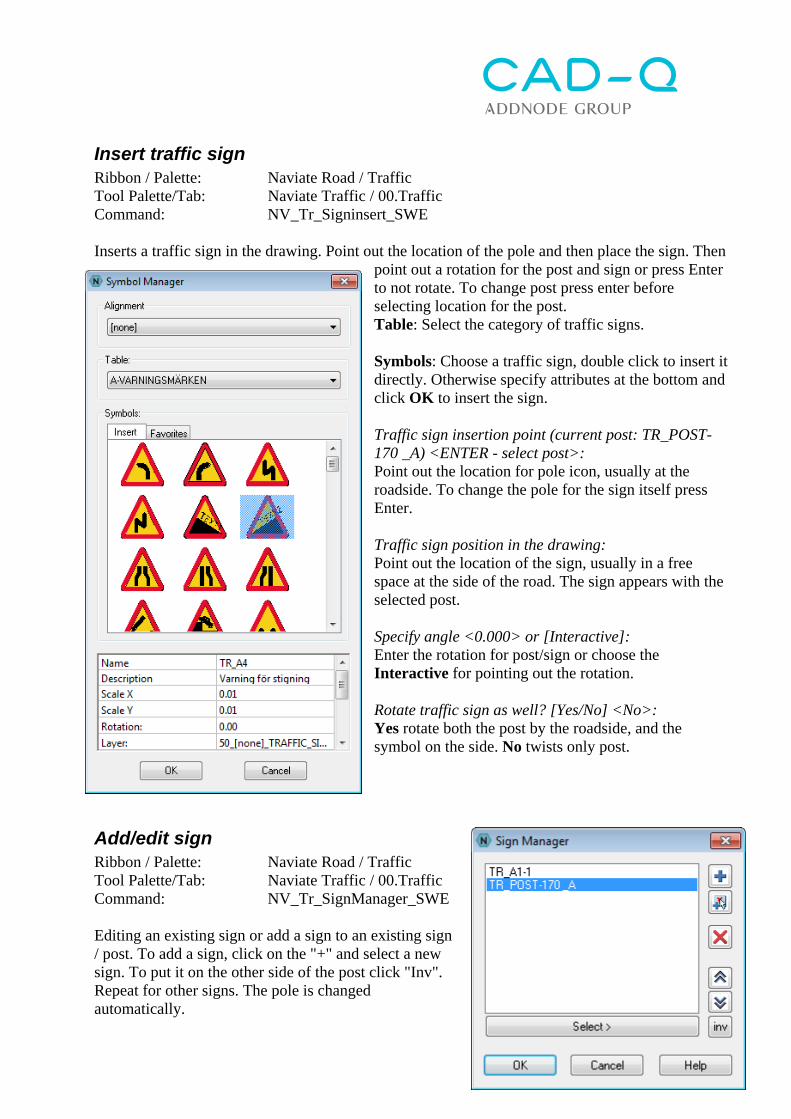
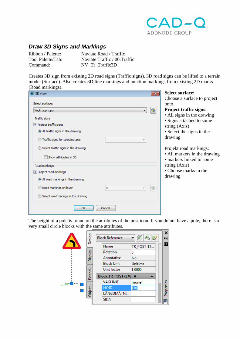
Transcript
Naviate Civil 3D 2016.1 - Read me (4.1)=New/modified in 2014, (4.2)=New/modified in 2014.2 (5.1)=New/modified in 2014.3/2015.1, (5.2)=New/modified in 2015.2 (6.1) = New/modified in 2015.3/2016.1 General ............................................................................................................................................... 4 New in template file 2015.3/2016.1 ................................................................................................... 5 Naviate tool palettes ........................................................................................................................... 7 Naviate Common Tool Paletts/ Common Commands ....................................................................... 9
General Naviate Infrastructure uses the basic functionality of AutoCAD Civil 3D and simplifies the usage of the program. Naviate Infrastructure consists of the following parts: Tool Palettes with methodology. Contains both translated Civil 3D commands as well as
Naviate functions. Ribbon tabs with Naviate functions. Some Civil 3D features are also included on these Ribbon
tabs. Expanded drawing template: _AutoCAD Civil 3D 2015 Naviate SWE.dwt External files for managing catalogs, reports, material handling, etc. Special developed subassemblies for road, rail and water and wastewater engineering
New in template file 2015.3/2016.1 With the command “Import styles and settings for Naviate” you can easily check the differences with a previous DWG or template file.
Naviate Ribbons (5.1) Naviate Infrastructure contains four different ribbon tabs:
Naviate o General features for the Help, About/License, Naviate Properties and
Import / Export functions o Commands to activate Ribbon tabs for Naviate W&S, Naviate Road and Naviate
Landscape o Functions for Coordinate Symbols, Zoom and Layer management
Naviate W&S
Naviate Road
Naviate Landscape
A license for each module are activated only when a command is started, not when you load the Ribbon tab. On the far right is a button to close the Ribbon tab. If Civil 3D is exited without closing a modules ribbon, it will be automatically loaded the next time the Civil 3D starts. NOTE: The license for the module is not released when the Ribbon is closed!
Naviate tool palettes To toggle between different palettes right click on the edge of the tool palette. If the tool palette is docked, the edge is at the top. If the tool palette is undocked, the edge is either to the right or the left. Docked: Undocked:
Naviate contains the following palettes:
Naviate W&S Water and sewage design in plan, profile and section
Naviate Road Road design in plan, profile and section
Naviate subassemblies Subassemblies to build sections for Road, Railroad and W&S.
Naviate Infrastructures tool palettes organize commands in Civil 3D into a suggested workflow. The functions have also been given a more complete explanatory text that you find when you hoover the cursor over the function. The explanation text also has the name of the command in parentheses as it is found in Civil 3Ds menus or ribbons. See example below.
When opening the program the first time, the icons on the tool palettes are very large. This can be adjusted by right-clicking on a blank area on the tool palette and choose View Options.
Change Image size to the desired size. To change all palettes at the same time, set Apply to to All Palettes and click OK.
Naviate Common Tool Paletts/ Common Commands Several of Naviate Infrastructure tool palettes have tabs in common. These are:
Project Functions to handle object links (Data Shortcuts) Ground Data General functions for managing original data Surface Features for Surface modelling Plan Production Drawing Management (Plan Production Tools) Visualization Visualization functions
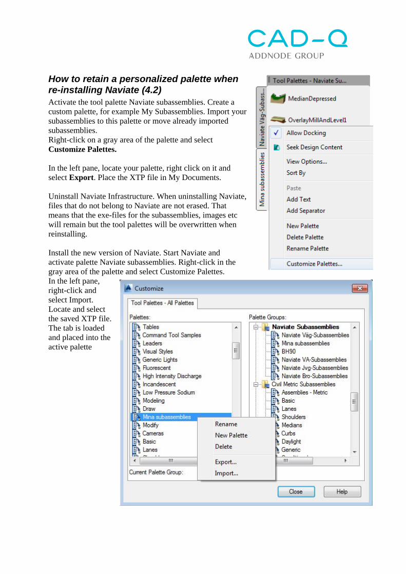
How to retain a personalized palette when re-installing Naviate (4.2) Activate the tool palette Naviate subassemblies. Create a custom palette, for example My Subassemblies. Import your subassemblies to this palette or move already imported subassemblies. Right-click on a gray area of the palette and select Customize Palettes. In the left pane, locate your palette, right click on it and select Export. Place the XTP file in My Documents. Uninstall Naviate Infrastructure. When uninstalling Naviate, files that do not belong to Naviate are not erased. That means that the exe-files for the subassemblies, images etc will remain but the tool palettes will be overwritten when reinstalling. Install the new version of Naviate. Start Naviate and activate palette Naviate subassemblies. Right-click in the gray area of the palette and select Customize Palettes. In the left pane, right-click and select Import. Locate and select the saved XTP file. The tab is loaded and placed into the active palette
Import PXY file (6.1) Ribbon / Palette: Naviate / General Tool Palette/Tab: Naviate / 10.Ground Data Command: NVPXYIn Create points and lines from a PXY file. The points are automatically added to point groups and lines can either be 2D polylines, 3D polylines or Feature Lines. Tab: Ground data Command: NVPXYin
Lines: Choose if lines should be created based on line information in the PXY file and if these lines will be created as 2D polylines, 3D polylines or Feature Lines. When selecting the Feature Lines option, a Site can be chosen. Points: Choose if Civil 3D points (COGO points) will be created. For each point code contained in the PXY file, a point group will be created, which controls the appearance of the points. Selected Point and Label Style are set as a default in each created Point Group. Point markings and Labels can be rotated to match the direction of the previous or the following points marking and label. Settings for points of non-even stations: Choose if points that are outside the set interval should be sorted into a point group.
Import GEO file Ribbon / Palette: Naviate / General Tool Palette/Tab: Naviate / 10.Ground Data Command: NVGEOIn Creates points, lines, arcs and circles based on a GEO file. Points will be AutoCAD points and the lines will be 2D Polylines. Tab: Ground Data Command: NVGEOin
Import TIT file Ribbon / Palette: Naviate / General Tool Palette/Tab: Command: NVTITIn Creates an alignment based on a TIT file. Tab: Ground Data Command: NVTITin
Import NYL file Ribbon / Palette: Naviate / General Tool Palette/Tab: Command: NVNYLIn Creates a profile based on a NYL file. Tab: Ground Data Command: NVNYLin
Export PXY file Ribbon / Palette: Naviate / General Tool Palette/Tab: Naviate / 10.Ground Data Command: NVPXYOut Creates a coordinate file from selected points or point groups
Point number/name format: Choose whether points should be numbered with integer numbers or decimal division per line. The Start Value sets the starting value for the first point. Set Feature line point code from: Selects if the name of the point code for selected lines are retrieved from the layer, the line type name, the Feature line style, the Feature line name or an optional code. Points: Click the button and select the Civil 3D points to be exported. If points were selected when the function started, they will be automatically selected. Lines: Click the button and select the lines to be exported. If the lines were selected when the function started, they will be automatically selected. Point groups: Select the point groups to be exported. Open the file in Notepad after export: If this is checked, the file will open automatically in Notepad after export. OK: Click OK to type in the name of the exported file.
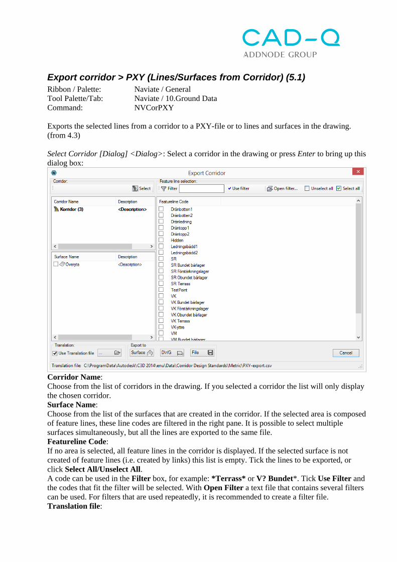
Export corridor > PXY (Lines/Surfaces from Corridor) (5.1) Ribbon / Palette: Naviate / General Tool Palette/Tab: Naviate / 10.Ground Data Command: NVCorPXY Exports the selected lines from a corridor to a PXY-file or to lines and surfaces in the drawing. (from 4.3) Select Corridor [Dialog] <Dialog>: Select a corridor in the drawing or press Enter to bring up this dialog box:
Corridor Name: Choose from the list of corridors in the drawing. If you selected a corridor the list will only display the chosen corridor. Surface Name: Choose from the list of the surfaces that are created in the corridor. If the selected area is composed of feature lines, these line codes are filtered in the right pane. It is possible to select multiple surfaces simultaneously, but all the lines are exported to the same file. Featureline Code: If no area is selected, all feature lines in the corridor is displayed. If the selected surface is not created of feature lines (i.e. created by links) this list is empty. Tick the lines to be exported, or click Select All/Unselect All. A code can be used in the Filter box, for example: *Terrass* or V? Bundet*. Tick Use Filter and the codes that fit the filter will be selected. With Open Filter a text file that contains several filters can be used. For filters that are used repeatedly, it is recommended to create a filter file. Translation file:
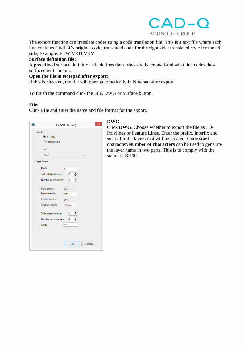
The export function can translate codes using a code translation file. This is a text file where each line contains Civil 3Ds original code; translated code for the right side; translated code for the left side, Example: ETW;VKH;VKV Surface definition file: A predefined surface definition file defines the surfaces to be created and what line codes these surfaces will contain. Open the file in Notepad after export: If this is checked, the file will open automatically in Notepad after export. To finish the command click the File, DWG or Surface button. File: Click File and enter the name and file format for the export.
DWG: Click DWG. Choose whether to export the file as 3D-Polylines or Feature Lines. Enter the prefix, interfix and suffix for the layers that will be created. Code start character/Number of characters can be used to generate the layer name in two parts. This is to comply with the standard BH90.
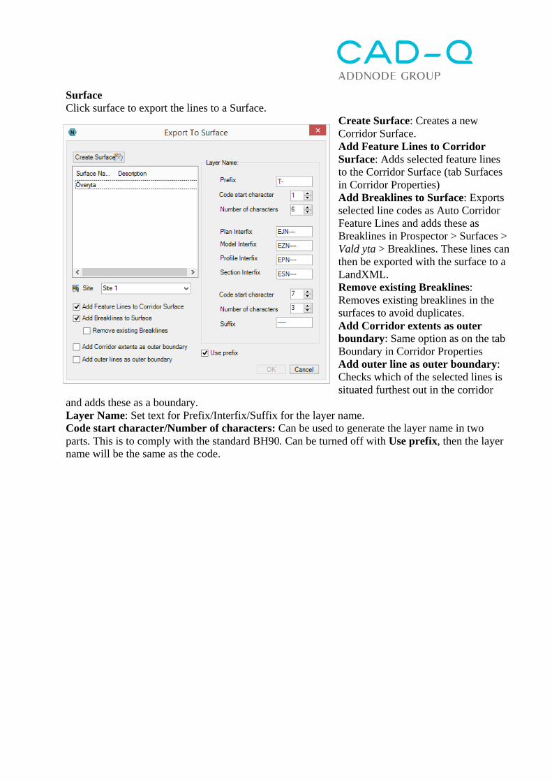
Surface Click surface to export the lines to a Surface.
Create Surface: Creates a new Corridor Surface. Add Feature Lines to Corridor Surface: Adds selected feature lines to the Corridor Surface (tab Surfaces in Corridor Properties) Add Breaklines to Surface: Exports selected line codes as Auto Corridor Feature Lines and adds these as Breaklines in Prospector > Surfaces > Vald yta > Breaklines. These lines can then be exported with the surface to a LandXML. Remove existing Breaklines: Removes existing breaklines in the surfaces to avoid duplicates. Add Corridor extents as outer boundary: Same option as on the tab Boundary in Corridor Properties Add outer line as outer boundary: Checks which of the selected lines is situated furthest out in the corridor
and adds these as a boundary. Layer Name: Set text for Prefix/Interfix/Suffix for the layer name. Code start character/Number of characters: Can be used to generate the layer name in two parts. This is to comply with the standard BH90. Can be turned off with Use prefix, then the layer name will be the same as the code.
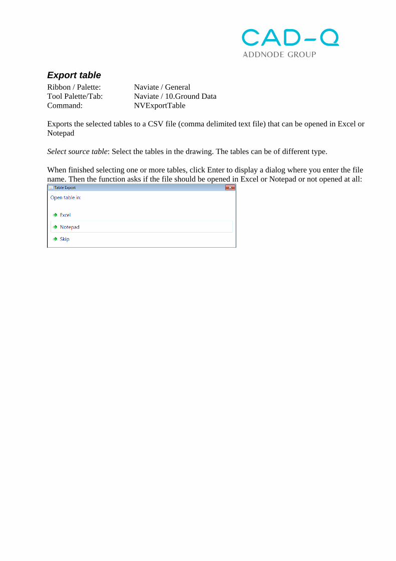
Export table Ribbon / Palette: Naviate / General Tool Palette/Tab: Naviate / 10.Ground Data Command: NVExportTable Exports the selected tables to a CSV file (comma delimited text file) that can be opened in Excel or Notepad Select source table: Select the tables in the drawing. The tables can be of different type. When finished selecting one or more tables, click Enter to display a dialog where you enter the file name. Then the function asks if the file should be opened in Excel or Notepad or not opened at all:
Create coordinate marker Ribbon / Palette: Naviate / Drawing Tool Palette/Tab: Naviate / 70.Plan Production Command: NVGridLabel Creates a grid of coordinate markers with coordinate values. With the function "Settings coordinate marker / values" you can set the desired coordinate marker style and the coordinate Label Style. Click "Add". 10mm markers no values 10mm marker, XY-label 100mm markers=grid!
With the function "Create coordinate marker" a grid is created with the settings as above. This function automatically snaps at 100mm in relation to the selected drawing scale. With the function "Change the marker/values" you can add X/Y coordinates to existing coordinate crosses. Select one or more coordinate cross in the drawing (Hint: You can select with a window in the drawing and then use the filter at the top of the Properties window to only see the "General Note Labels"). Then change the "General Note Label Style" in the Properties window:
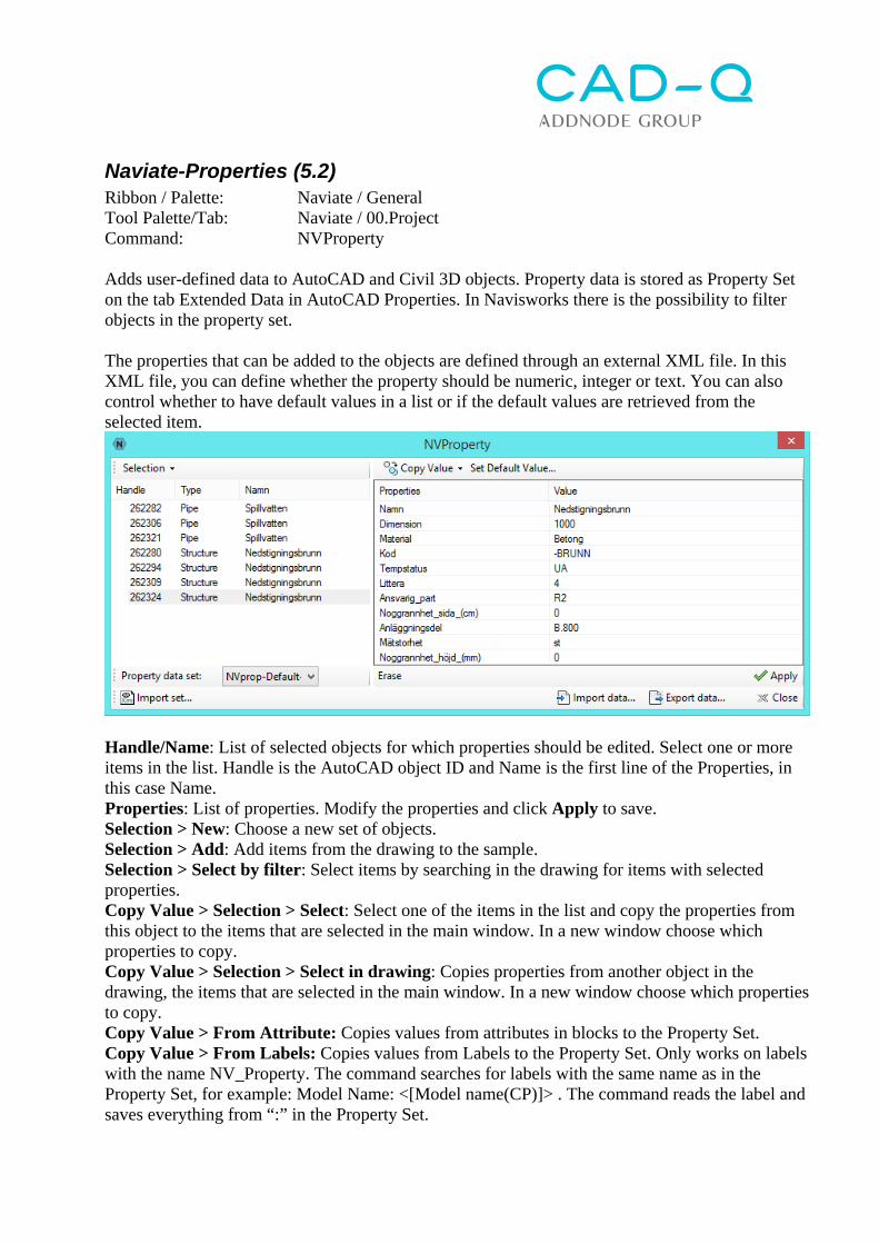
Naviate-Properties (5.2) Ribbon / Palette: Naviate / General Tool Palette/Tab: Naviate / 00.Project Command: NVProperty Adds user-defined data to AutoCAD and Civil 3D objects. Property data is stored as Property Set on the tab Extended Data in AutoCAD Properties. In Navisworks there is the possibility to filter objects in the property set. The properties that can be added to the objects are defined through an external XML file. In this XML file, you can define whether the property should be numeric, integer or text. You can also control whether to have default values in a list or if the default values are retrieved from the selected item.
Handle/Name: List of selected objects for which properties should be edited. Select one or more items in the list. Handle is the AutoCAD object ID and Name is the first line of the Properties, in this case Name. Properties: List of properties. Modify the properties and click Apply to save. Selection > New: Choose a new set of objects. Selection > Add: Add items from the drawing to the sample. Selection > Select by filter: Select items by searching in the drawing for items with selected properties. Copy Value > Selection > Select: Select one of the items in the list and copy the properties from this object to the items that are selected in the main window. In a new window choose which properties to copy. Copy Value > Selection > Select in drawing: Copies properties from another object in the drawing, the items that are selected in the main window. In a new window choose which properties to copy. Copy Value > From Attribute: Copies values from attributes in blocks to the Property Set. Copy Value > From Labels: Copies values from Labels to the Property Set. Only works on labels with the name NV_Property. The command searches for labels with the same name as in the Property Set, for example: Model Name: <[Model name(CP)]> . The command reads the label and saves everything from “:” in the Property Set.
Copy Value > Default: Loads default values that are defined in the selected XML file. The properties may be fixed values or values that are read from the object, eg Pipe.InnerDiameterOrWidth or Structure.StyleName or Polyline.Length. The values that can be used on different object types are listed with the command NVPropList. In a new window choose which properties to copy. Apply: Saves the properties of the selected items. Property File: Open: Select the XML file that defines the properties to be added to items. Export: Exporting the properties of selected objects to a CSV file that can be opened and edited in MS Excel or Notepad / Notepad. One column is the object's identity (Handle) which makes it possible to import the edited data back into objects. Import: Importing property data from a CSV file. The properties in the Properties-window:
NV-Properties on 3DFace (5.2) Ribbon / Palette: Naviate / General Tool Palette/Tab: Naviate / 00.Project Command: NVPropertyOn3DFace Adds Naviate Properties to 3D Faces. First use Extract Objects to extract 3DFaces from a surface or corridor. Select objects: Choose 3DFaces Select Alignment [No Alignment]: Choose an alignment to get station and offset values from Select Corridor [No Corridor]: Choose a corridor. Only for identification purposes. Enter Code: Add a code Enter Full Code <0>: Add a full code, current layer is suggested.
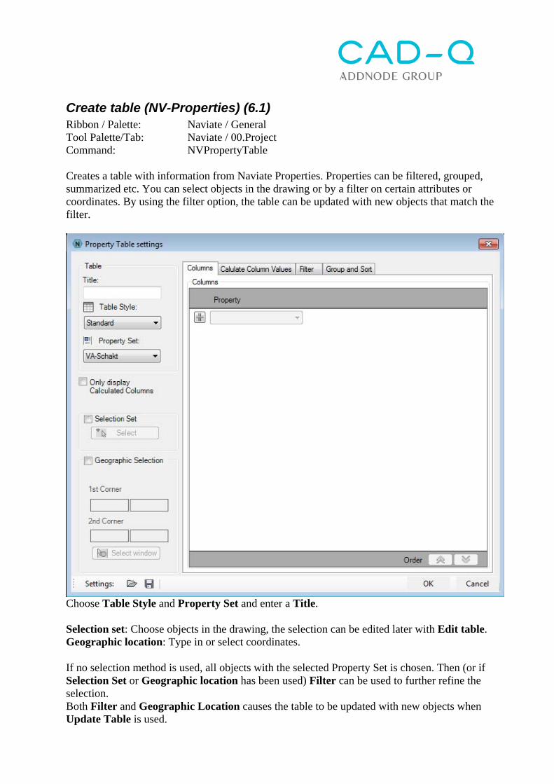
Create table (NV-Properties) (6.1) Ribbon / Palette: Naviate / General Tool Palette/Tab: Naviate / 00.Project Command: NVPropertyTable Creates a table with information from Naviate Properties. Properties can be filtered, grouped, summarized etc. You can select objects in the drawing or by a filter on certain attributes or coordinates. By using the filter option, the table can be updated with new objects that match the filter.
Choose Table Style and Property Set and enter a Title. Selection set: Choose objects in the drawing, the selection can be edited later with Edit table. Geographic location: Type in or select coordinates. If no selection method is used, all objects with the selected Property Set is chosen. Then (or if Selection Set or Geographic location has been used) Filter can be used to further refine the selection. Both Filter and Geographic Location causes the table to be updated with new objects when Update Table is used.
Columns: Sets columns for the table. Click the plus button to add a row. Calculate column Values: Set what columns to summarize. Filter: Set a search filter (click the plus button to add a row) Sort order: Set what column the rows should be sorted after.
Edit Table (NV-Properties) (5.2) Ribbon / Palette: Naviate / General Tool Palette/Tab: Naviate / 00.Project Command: NVPropertyTableEdit Edits the settings for an existing table with information from Naviate Properties.
Update Table (NV-Properties) (5.2) Ribbon / Palette: Naviate / General Tool Palette/Tab: Naviate / 00.Project Command: NVPropertyTableUpdate Updates the contents in an existing table with information from Naviate Properties.
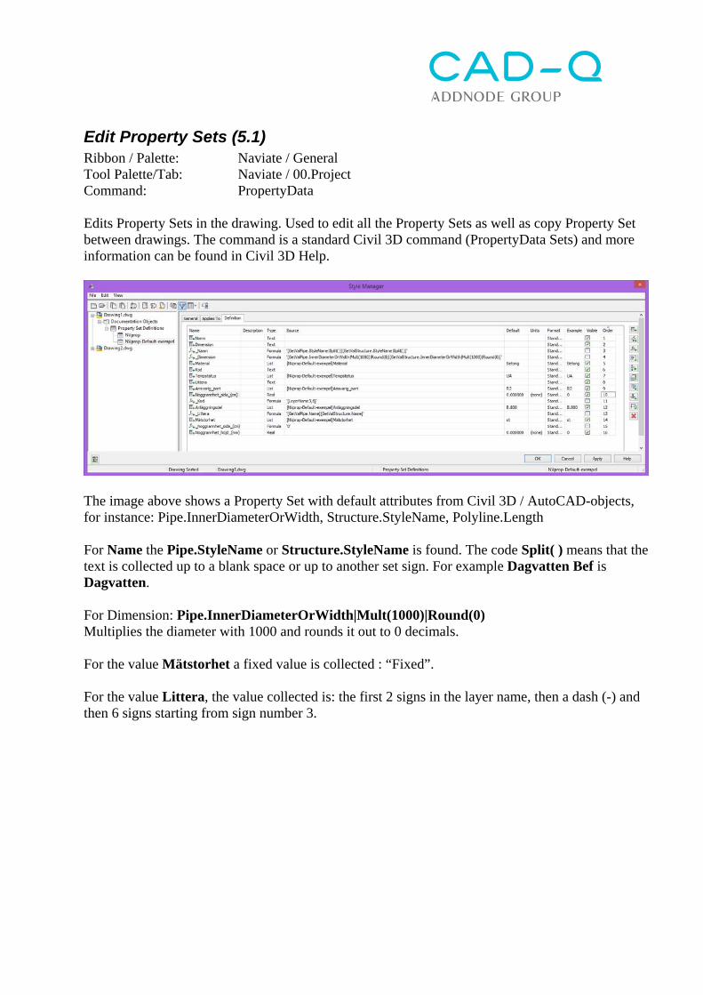
Edit Property Sets (5.1) Ribbon / Palette: Naviate / General Tool Palette/Tab: Naviate / 00.Project Command: PropertyData Edits Property Sets in the drawing. Used to edit all the Property Sets as well as copy Property Set between drawings. The command is a standard Civil 3D command (PropertyData Sets) and more information can be found in Civil 3D Help.
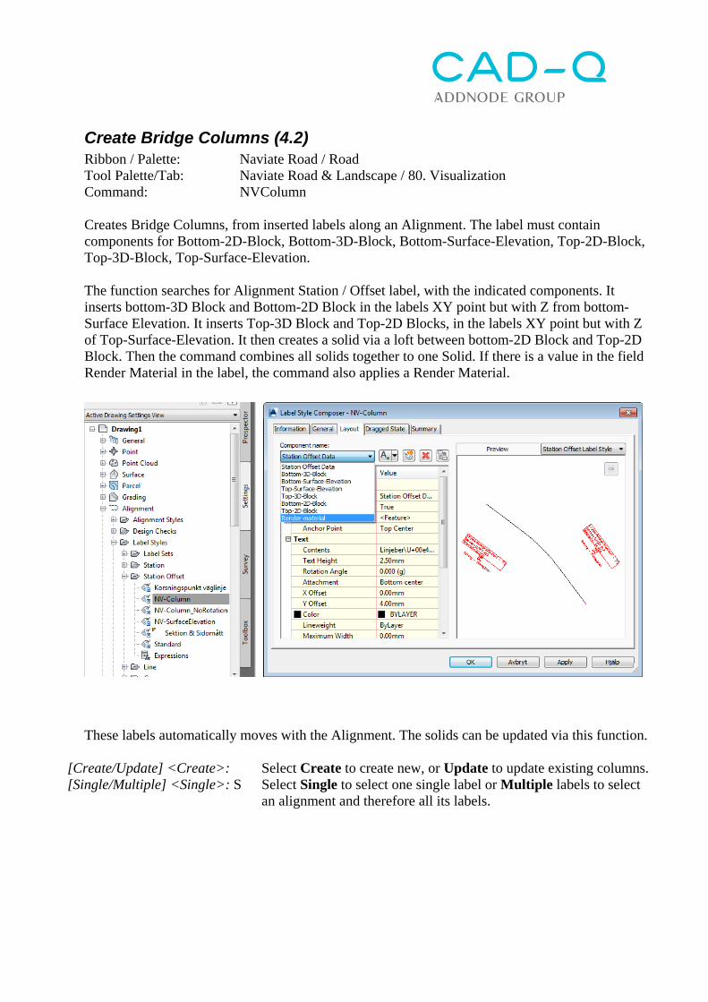
The image above shows a Property Set with default attributes from Civil 3D / AutoCAD-objects, for instance: Pipe.InnerDiameterOrWidth, Structure.StyleName, Polyline.Length For Name the Pipe.StyleName or Structure.StyleName is found. The code Split( ) means that the text is collected up to a blank space or up to another set sign. For example Dagvatten Bef is Dagvatten. For Dimension: Pipe.InnerDiameterOrWidth|Mult(1000)|Round(0) Multiplies the diameter with 1000 and rounds it out to 0 decimals. For the value Mätstorhet a fixed value is collected : “Fixed”. For the value Littera, the value collected is: the first 2 signs in the layer name, then a dash (-) and then 6 signs starting from sign number 3.
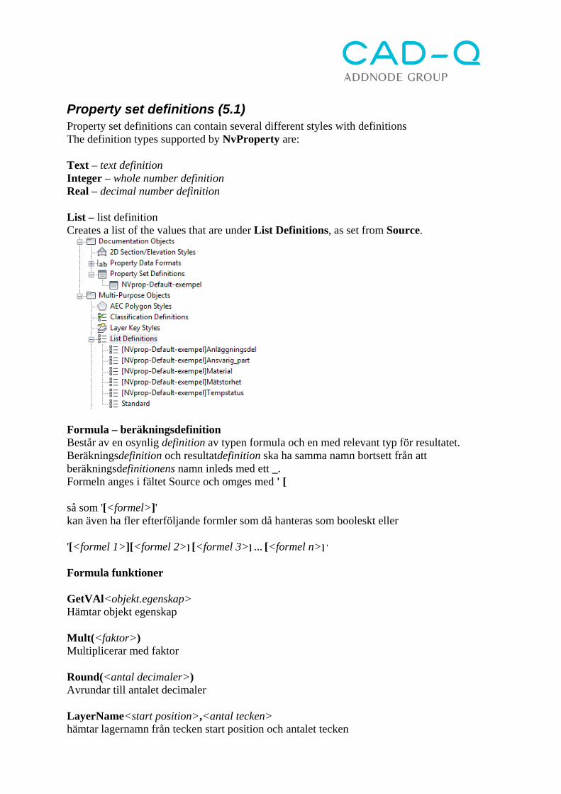
Property set definitions (5.1) Property set definitions can contain several different styles with definitions The definition types supported by NvProperty are: Text – text definition Integer – whole number definition Real – decimal number definition List – list definition Creates a list of the values that are under List Definitions, as set from Source.
Formula – beräkningsdefinition Består av en osynlig definition av typen formula och en med relevant typ för resultatet. Beräkningsdefinition och resultatdefinition ska ha samma namn bortsett från att beräkningsdefinitionens namn inleds med ett _. Formeln anges i fältet Source och omges med ' [ så som '[<formel>]' kan även ha fler efterföljande formler som då hanteras som booleskt eller '[<formel 1>][<formel 2>] [<formel 3>] … [<formel n>] '
Formula funktioner GetVAl<objekt.egenskap> Hämtar objekt egenskap Mult(<faktor>) Multiplicerar med faktor Round(<antal decimaler>) Avrundar till antalet decimaler LayerName<start position>,<antal tecken> hämtar lagernamn från tecken start position och antalet tecken
Split(<bryt tecken>) Kapar av förgående värde vid först funna tecken Ex. '[GetValPipe.InnerDiameterOrWidth|Mult(1000)|Round(0)][GetValStructure.InnerDiameterOrWidth|Mult(1000)|Round(0)]' Har värdet av innerdiameter multiplicerat med 1000 utan decimaler för objektet Pipe eller värdet innerdiameter multiplicerat med 1000 utan decimaler för objektet för objektet Structure.
NVPropList Ribbon / Palette: Naviate / General Tool Palette/Tab: Naviate / 00.Project Command: NVPropList The command lists the values that can be used as default values for different types of objects in the XML file for property data e.g.. Pipe.InnerDiameterOrWidth Structure.StyleName Polyline.Length
Import layer Ribbon / Palette: Naviate / Drawing Tool Palette/Tab: Command: NVLayerImportDesc Importing layer, description text, etc. from a text file The text file should comma-separated with columns containing, in this order (additional columns can be added after): Name;Color;Linetype;Lineweight;Description First select the file to import from. Then the function writes out the first two lines in the file: Name;Color;Linetype;Lineweight;Description_SWE;Description_Eng W-51CB--TP-------------;240;Continuous;0.25;STORM SEWER - TEXT (PROFILE) SWEDISH;SEWAGE - TEXT (PROFILE) SWEDISH List delimiter <;>: Enter what character is column seperator Enter Description column <5>: Specify which column is the description Skip first row? [Yes/No] <Yes>: Enter if the first line should be skipped (for headlines) If the layer does not exist, it will be created according to your settings. If the layer exists, the Description is added and the color etc. is changed. The text file can easily be created by highlighting and copying all the layers in the Layer Manager and paste into Excel. From there it can be edited and saved as a CSV-file.
Rename layer Ribbon / Palette: Naviate / Drawing Tool Palette/Tab: Command: NVLayerDescToName Renames the layer with the description text "Description” and places the layers name as the Description.
Layer from object-style (4.2) Ribbon / Palette: Naviate / Drawing Tool Palette/Tab: Command: NVObjectLayerFromStyle Changes the layer of Civil-objects by reading the layer from the objects style. Which style component that controls the layer is controlled through an editable XML-file. Default file location for the XML-file is C:\ProgramData\Autodesk\C3D 2015\enu\Data\Naviate-SWE\ nvObjLayerStyle.xml
Naviate Landscape (4.2) Naviate Landscapes tool palette contains the tabs:
Elevation Management – commands to modify Feature lines o Create and Modify Feature Lines o Elevation controls o Adding breakpoint or elevation point o Labels o Adjust individual elevations
Profile/Section – Functions to create:
o Section line (alignment) o Profile drawing (Profile View) o Section drawing (Section View)
Slopes - Functions to create and modify gradings Layer - Functions to turn on / off layers and
change the color of layers
Naviate Landscape Ribbon contains the following functions:
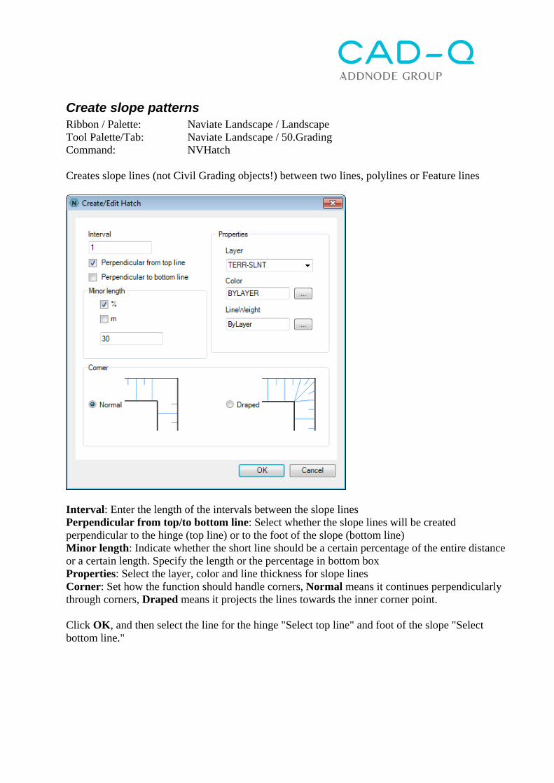
Interval: Enter the length of the intervals between the slope lines Perpendicular from top/to bottom line: Select whether the slope lines will be created perpendicular to the hinge (top line) or to the foot of the slope (bottom line) Minor length: Indicate whether the short line should be a certain percentage of the entire distance or a certain length. Specify the length or the percentage in bottom box Properties: Select the layer, color and line thickness for slope lines Corner: Set how the function should handle corners, Normal means it continues perpendicularly through corners, Draped means it projects the lines towards the inner corner point. Click OK, and then select the line for the hinge "Select top line" and foot of the slope "Select bottom line."
Edit slope patterns Ribbon / Palette: Naviate Landscape / Landscape Tool Palette/Tab: Naviate Landscape / 50.Grading Command: NVHEdit Changes the setting for slope lines created between the two lines. Can also be used to update the slope lines when you changed the top / bottom line Select hatch: Select the slope pattern to change, that opens the dialog above. If you just want to get the slope lines updated, just click OK.
Create Dynamic Feature Line (4.1) Ribbon / Palette: Naviate Landscape / Landscape Tool Palette/Tab: Naviate Landscape / 30. Elevation Command: NVOffsetFeature Creates a dynamic parallel Feature Line (F-Line) along the selected Feature Line. The parallel-copied line can be updated after the original line changed. The parallel-copied line must be in the same Site. Note that the lines in the Site cannot lie directly above each other, they must have a small (1mm) offset. Select object [Release/Update]: Select a Feature Line in the drawing or select Release to disconnect the dynamic coupling of a feature line or Update to update a dynamically linked feature line. Pick side to offset: Click on the side that the line is to be created Distance <10.0000>: Enter lateral dimension Specify elevation or [Slope/Grade] <1.0000>: Enter height difference or click Slope to specify the slope of 1: X or click Grade to enter the grade in %.
Update Dynamic Feature Line (4.1) Ribbon / Palette: Naviate Landscape / Landscape Tool Palette/Tab: Naviate Landscape / 30. Elevation Command: NVOffsetFeature U Update the dynamic parallel Feature Line (F-Line) after changes in the original line. Select object [Release / Update]: Select Update to update a dynamically linked feature line. Specify update [One level / Nested] <One level>: Ability to select whether the update should only go one level down in the hierarchy (One level) or if it should search for nested (Nested) levels of parallel copied lines, ie if one parallel copied a line from a parallel copied line. The function erases the selected line and recreates it as a parallel copy of the original line. Any changes to the line are cleared.
Create Surface Feature Line (4.1) Ribbon / Palette: Naviate Landscape / Landscape Tool Palette/Tab: Naviate Landscape / 30. Elevation Command: NVSurfaceFeature Projects a Feature line on the selected surface with a specified height adjustment. Select Feature Line [Update]: Select a Feature line in the drawing, or select Update to update a line that is already projected by Naviate on to a terrain model. Select surface in drawing or in dialogue [Dialog] <dialog>: Select a terrain model in the drawing or press enter to select in a dialog box. Enter Elevation Offset <0.1000>: Enter a height value that the line is to be lifted above the terrain model.
Update Surface Feature Line (4.1) Ribbon / Palette: Naviate Landscape / Landscape Tool Palette/Tab: Naviate Landscape / 30. Elevation Command: NVSurfaceFeature U Updates a Feature line coupled to a terrain model. If a parallel copy is created by the current line, the command can also update the copy. Select Feature Line to Update [All]: Select a Feature line in the drawing, or select All to update all the lines that are projected by Naviate on to a surface. Update referenced Feature Lines [Yes / No]: Y Answer Yes to also update parallel copied lines.
Create dynamic line-set (4.2) Ribbon / Palette: Naviate Landscape / Landscape Tool Palette/Tab: Naviate Landscape / 30. Elevation Command: NV_AK_Grading Creates a dynamic set of lines by parallel copying an existing polyline in elevation/side. The parallel lines copied are automatically updated if the original line changes. Select polyline or ENTER to finish: Select side: Select the starting point or ENTER to apply to entire length... Select Polyline, click on a side for parallel copying, and press Enter to get a copy along the whole line or point out the start and endpoint. In the dialog box, you can then create your own "Set" by copying steps, with the top plus button. Some features may project toward the surface in the "Target surface". "Grading Name" is a term for the line set (grading) created along the selected line. In the bottom list, create several steps that parallel copy lines, one after the other.
Edit dynamic line-set (4.2) Ribbon / Palette: Naviate Landscape / Landscape Tool Palette/Tab: Naviate Landscape / 30. Elevation Command: NV_AK_Grading_Edit Edits an existing line set. Opens the dialog box above to make adjustments.
Extrude along path Ribbon / Palette: Naviate Landscape / Landscape Naviate Road / Road Tool Palette/Tab: Naviate Landscape & Road / 80.Visualization Command: NVExtrude Extrudes a "polyline-profile" along the line which creates a solid. The profile can also be a block. Can be used to create for instance curbs or retaining walls. The profile is drawn as a polyline. If you use a block the command uses the first polyline that is found in the block. The settings for how the solid is extruded is stored on the solid so that it can be updated after changes to the profile or the line. Select Profile [Block/Update/Flip]: Select a polyline in the drawing. The option Block allows the selection of a block instead. The option Update provides the ability to update an existing solid created by the command. The option Flip allows you to flip (reverse) side of an existing solid created by the command. Select Basepoint: Select the point to follow the line Rotation <0>: Enter rotary or touch two points Select Path: Select the line profile to be extruded along Flip object [Yes/No] <No>: Set the profile to be flipped = creates a mirror image
Update solid Ribbon / Palette: Naviate Landscape / Landscape Naviate Road / Road Tool Palette/Tab: Naviate Landscape & Road / 80.Visualization Command: NVExtrude U Updating an extruded solid after the line or profile changed.
Flip solid (4.1) Ribbon / Palette: Naviate Landscape / Landscape Naviate Road / Road Tool Palette/Tab: Naviate Landscape & Road / 80.Visualization Command: NVExtrude F Flip (turn) side of an extruded solid.
Slope Arrow (F-line) (6.1) Ribbon / Palette: Naviate Landscape / Landscape Tool Palette/Tab: Naviate Landscape / 30. Elevation Command: NVCreateFeatureline Draws a Feature line that automatically gets a slope label. This command works the same way as Civil 3D's default function "Create Feature Line" but after the command ends, a label is automatically added and command starts again. The label that is inserted is defined in the template as follows:
The function starts with the dialogue to create a Feature Line, where Site, Name, Style can be chosen. Click OK to create a Feature Line in the usual manner. See Civil 3D Help for detailed instructions. When the command is complete, you get options to add the slope arrow to a surface
Yes Add the created line to the selected surface (You get the same option after next line is created) Yes to all Add the created line to the selected surface, and do the same with all the lines till the command is canceled. No Do not add the created line to a surface (You get the same option after the next line is created) No to all Do not add the created line to surface, and do the same with all the lines till the command is canceled. Cancel Cancels the command without adding the line to a surface. The command then starts again and more slope arrows can be created.
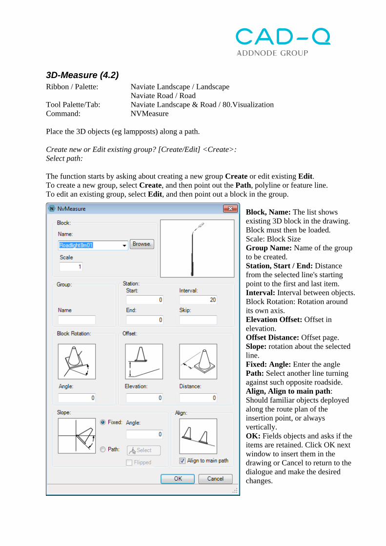
3D-Measure (4.2) Ribbon / Palette: Naviate Landscape / Landscape Naviate Road / Road Tool Palette/Tab: Naviate Landscape & Road / 80.Visualization Command: NVMeasure Place the 3D objects (eg lampposts) along a path. Create new or Edit existing group? [Create/Edit] <Create>: Select path: The function starts by asking about creating a new group Create or edit existing Edit. To create a new group, select Create, and then point out the Path, polyline or feature line. To edit an existing group, select Edit, and then point out a block in the group.
Block, Name: The list shows existing 3D block in the drawing. Block must then be loaded. Scale: Block Size Group Name: Name of the group to be created. Station, Start / End: Distance from the selected line's starting point to the first and last item. Interval: Interval between objects. Block Rotation: Rotation around its own axis. Elevation Offset: Offset in elevation. Offset Distance: Offset page. Slope: rotation about the selected line. Fixed: Angle: Enter the angle Path: Select another line turning against such opposite roadside. Align, Align to main path: Should familiar objects deployed along the route plan of the insertion point, or always vertically. OK: Fields objects and asks if the items are retained. Click OK next window to insert them in the drawing or Cancel to return to the dialogue and make the desired changes.
Max/Min for surfaces (6.1) Ribbon / Palette: Naviate Landscape / Landscape Naviate Road / Road Tool Palette/Tab: Naviate / 20. Surface Command: NVElevationFromSurface Creates or changes points and point groups for highest, lowest or mean value of two surfaces.
Choose if the command should edit an existing point group, create points and a point groups or export the resulting points to a NEZ-file. Surface 1 o Surface 2 Choose what two surfaces will be used Get Points From Choose what points to create Surface 1 Points will be created in all nodes of Surface 1 Surface 2 Points will be created in all nodes of Surface 2 Surface 1&2 Points will be created in all nodes of Surface 1 och 2
Within Surface 1&2 Points will be created in all nodes that fall within both Surface 1 och 2.
Elevation method Choose if the points should get their elevations from the highest, the lowest of the mean value of Surface 1 and 2
Create Houses Ribbon / Palette: Naviate Landscape / Landscape Tool Palette/Tab: Naviate Landscape & Road / 80.Visualization Command: NVCreateHouse Creates house by extruding 3D polylines representing the roof towards a surface The function looks for polylines on selected layers (or selected objects) and extrude them either against a surface or to a specified depth. The Polyline is assumed to represent the roof of the house. The facade of the house is created by the extrusion and depending on whether it is a 3D or 2D polyline becomes a Surface Extrusion or 3DSOLID. The command also builds a Mesh by connecting the roof breakpoints. In a rendered view it can look like the picture below
Select by Layer / Select Objects: Choose either to select objects via layer (click [Layers]) or by selecting the drawing (click [Select] button). House Layer: Write a new layer or select a layer in the list, for the facade. Roof Layer: Write a new layer or select a layer in the list, for the roof. Ground Surface [Select]: Select the terrain / surface in the drawing. House depth: Enter the depth of the facade. If a terrain model also selected as preferred facade down in the terrain model, with specified depth. [Clean up] Run a "Drawing cleanup" and connects all the lines on the selected layer to polylines
[Create House] Creates houses.
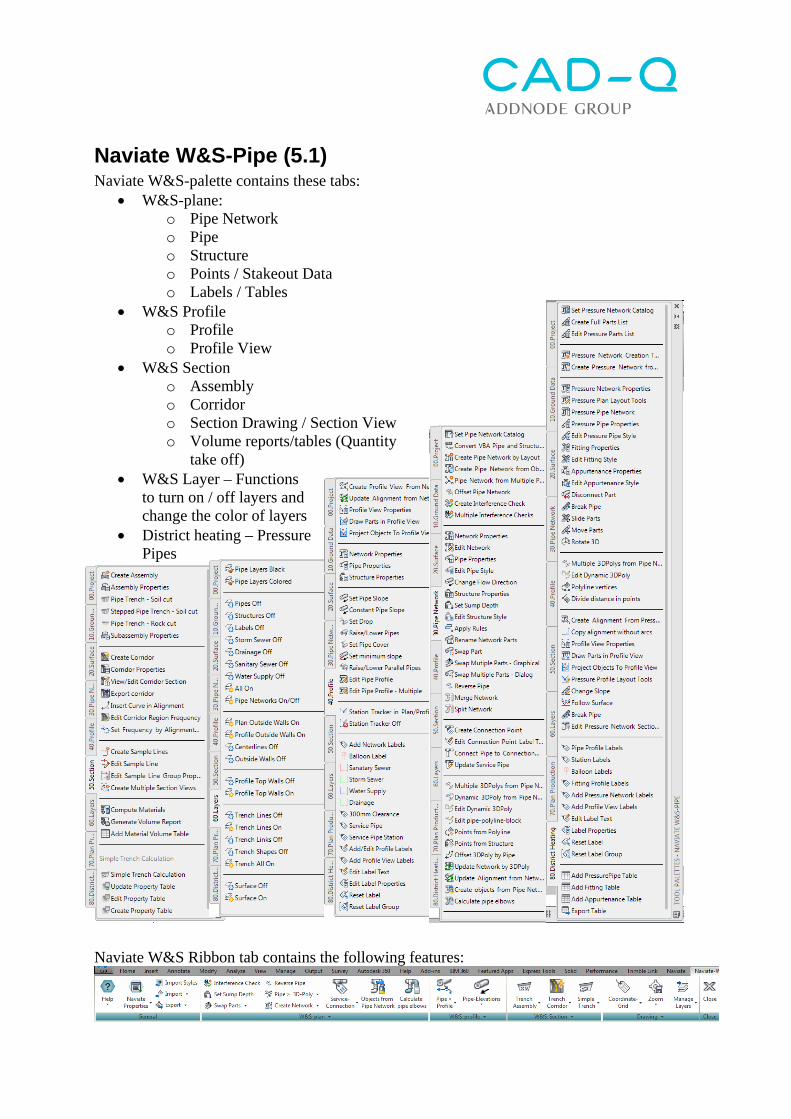
Naviate W&S-Pipe (5.1) Naviate W&S-palette contains these tabs:
W&S-plane: o Pipe Network o Pipe o Structure o Points / Stakeout Data o Labels / Tables
W&S Profile o Profile o Profile View
W&S Section o Assembly o Corridor o Section Drawing / Section View o Volume reports/tables (Quantity
take off) W&S Layer – Functions
to turn on / off layers and change the color of layers
District heating – Pressure Pipes
Naviate W&S Ribbon tab contains the following features:
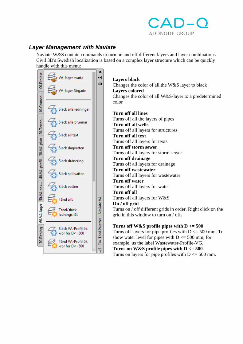
Layer Management with Naviate Naviate W&S contain commands to turn on and off different layers and layer combinations. Civil 3D's Swedish localization is based on a complex layer structure which can be quickly handle with this menu:
Layers black Changes the color of all the W&S layer to black Layers colored Changes the color of all W&S-layer to a predetermined color Turn off all lines Turns off all the layers of pipes Turn off all wells Turns off all layers for structures Turn off all text Turns off all layers for texts Turn off storm sewer Turns off all layers for storm sewer Turn off drainage Turns off all layers for drainage Turn off wastewater Turns off all layers for wastewater Turn off water Turns off all layers for water Turn off all Turns off all layers for W&S On / off grid Turns on / off different grids in order. Right click on the grid in this window to turn on / off. Turns off W&S profile pipes with D <= 500 Turns off layers for pipe profiles with D <= 500 mm. To show water level for pipes with D <= 500 mm, for example, us the label Wastewater-Profile-VG. Turns on W&S profile pipes with D <= 500 Turns on layers for pipe profiles with D <= 500 mm.
Create multiple interference checks Ribbon / Palette: Naviate W&S / W&S-plan Tool Palette/Tab: Naviate W&S / 30.Pipe Network Command: NVCreateInterferenceCheck Identifies the network elements that collide with others or is within a specified distance. This function creates Interference checks between all selected pipe networks. The function uses the settings that are pre-defined for the command Create Interference Check (Tool Space> Settings> Pipe Networks> Commands> Create Interference Check, right click> Edit Command Settings)
Tick the networks to be checked, and click Check Selected or click Check All to check all networks with each other. The function concludes by reporting the number of collision checks created and how many collisions that existed:
The collision checks can then be found in the Tool Space / Prospector:
Set Sump Depth Ribbon / Palette: Naviate W&S / W&S-plan Tool Palette/Tab: Naviate W&S / 30.Pipe Network Command: NVSetSumpDepth Changes the Sump Depth for selected structures in a pipe network. Some features of Civil 3D creates 2m Sump Depth on all structures, this can be corrected with this function. Command: NVSetSumpDepth Enter sump depth: 2 Enter the Sump Depth Sump depth for the entire Network/single Structure [Network/Single] <Single>: N
Select whether the change will be implemented for an entire network (Network) or single structures (Single).
Select pipe/structure: Select one or more structures
Flip Pipe (5.2) Ribbon / Palette: Naviate W&S / W&S-plan Tool Palette/Tab: Naviate W&S / 30.Pipe Network Command: NvReversePipeSingle Changes direction on a pipe Select pipe object or Undo: Click on the pipe that will be flipped. An arrow is created temporarily that shows the new direction, click on the pipe again to undo. Select pipe object or Undo: Click on the next pipe that shall be flipped, or click Enter to end the command.
Swap Multiple Parts – Graphic Ribbon / Palette: Naviate W&S / W&S-plan Tool Palette/Tab: Naviate W&S / 30.Pipe Network Command: NVSwapPart Swaps multiple parts (pipe or structure) by selecting a “copy from” part and the “copy to” parts. Use standard command Swap Part, to first swap the “copy from” part Command: NVSwapPart Select source Pipe or Structure: Select the object to be copied from. Select [Network/Singel] <Singel>: Select Network to apply the change to all management objects in a grid, then select a line item in the drawing. Select Single to select individual line item, then select the desired line item in the drawing.
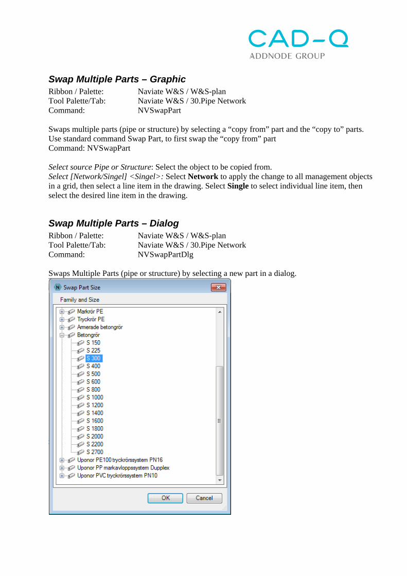
Swap Multiple Parts – Dialog Ribbon / Palette: Naviate W&S / W&S-plan Tool Palette/Tab: Naviate W&S / 30.Pipe Network Command: NVSwapPartDlg Swaps Multiple Parts (pipe or structure) by selecting a new part in a dialog.
Set Pipe Slope Ribbon / Palette: Naviate W&S / W&S-profile Tool Palette/Tab: Naviate W&S / 40.Profile Command: NVPipeSlopeDrop Changes starting elevation, slope and drop for one or more interconnected pipes Pick up slope pipe or structure: Select the first pipe, upstream Pick down slope pipe or structure: Select the last pipe, downstream Start from first or last pipe [First/Last] <First>: F (First= start from the first pipe and move forward, Last= start from the last pipe and go backwards) Set drop for Invert or Crown [Invert/Crown] <Invert>: I (calculate the drop from Invert or Crown of the pipes. Affects the drop only if the pipes have different dimension) Enter value to raise/lower first pipe start elevation <0.0>: 0 Enter pipe run slope in % <-0.5000>: -0.2 (Pipe slope, negative is downstream) Enter pipe drop in m <0.0200>: 0.02 (Drop in structure, positive value is downward) Minimum cover:1.57 for pipe :Pipe (1) (Lowest cover reported) Maximum cover:2.02 for pipe :Pipe (3) (Highest cover reported) Enter value to raise/lower first pipe start elevation <-0.0750>: (Now it is possible to do the calculation again and adjust any of the parameters. Press ESC to end)
Constant Pipe Slope Ribbon / Palette: Naviate W&S / W&S-profile Tool Palette/Tab: Naviate W&S / 40.Profile Command: NVPipeConstantSlope Set a constant slope for a series of connected pipe network parts. First pipe start elevation and last pipe end elevation is kept and the elevation difference minus pipe drop values is converted to a constant slope for selected pipes. (Naviate) Select Start Pipe/Structure: Select the first pipe Select Last Pipe/Structure: Select the last pipe Specify drop <0.0000>: Enter drop in the structure, positive value is downwards Slope: 0.2% Minimum cover: 1 for pipe: Pipe (4) Maximum cover: 1.404 for pipe: Pipe (6) The function concludes by reporting what slope was applied to the pipes and the Min and Max cover depth.
Set Drop Ribbon / Palette: Naviate W&S / W&S-profile Tool Palette/Tab: Naviate W&S / 40.Profile Command: NVPipeDrop Changes the elevation and drop for one or more connected pipes. Pick Starting pipe or structure: Select the first pipe Pick Ending pipe or structure: Select the last pipe Start from first or last pipe [First/Last] <First>: F (First= start from the first pipe and move forward, Last= start from the last pipe and go backwards) Enter value to raise/lower first pipe start elevation <0.0>: 0 Enter pipe drop in m <0.0200>: 0.02 (Drop in structure, positive value dowstream) Minimum cover:1.57 for pipe :Pipe (1) (Lowest cover is presented) Maximum cover:2.02 for pipe :Pipe (3) (Largest cover is presented) Enter value to raise/lower first pipe start elevation <-0.0750>: (now it is possible to do the calculation again and adjust any of the parameters. Press ESC to end)
Set minimum slope Ribbon / Palette: Naviate W&S / W&S-profile Tool Palette/Tab: Naviate W&S / 40.Profile Command: NVPipeSetMinSlope Checks all selected pipes and modifies slope for those who have less slope than entered minimum value. The slope is modified by changing the end elevation for that pipe and the following pipe start elevation is also modified to match the previous pipe, including drop. You must select whether the slope is going upslope or downslope. (Naviate) Select starting pipe: Select the first pipe Select ending pipe: Select the last pipe Enter minimum slope %: 1 Enter the minimum slope for pipe Specifies whether the slope of the pipe network is upstream or downstream [Upslope/Downslope] <Downslope>: D Enter D for slope downslope and U for upslope
Raise/lower pipes Ribbon / Palette: Naviate W&S / W&S-profile Tool Palette/Tab: Naviate W&S / 40.Profile Command: NVPipeChElev Raise/lower one or more connected pipes. Select first pipe/structure to raise/lower: Select the first pipe Select [Next pipe or structure/Entire network] <Next pipe or structure>: E (Select either the next pipe or press E to select all pipes in the grid) Enter value to add to all elevations <0.3000>: -0.2 (Enter the desired elevation) Minimum cover:1.77 for pipe :Pipe (1) (Lowest cover is presented ) Maximum cover:2.22 for pipe :Pipe (3) (Largest cover in presented) Enter value to add to all elevations <-0.2000>: (now it is possible to do the calculation again and adjust any of the parameters. Press ESC to end)
Set Pipe Cover Ribbon / Palette: Naviate W&S / W&S-profile Tool Palette/Tab: Naviate W&S / 40.Profile Command: NVPipeChCover Modifies elevation for a series of connected pipes or a whole network, by setting cover for start and end pipe elevation. Note that Minimum Cover therefore can differ from entered cover value. Select first pipe/structure to raise/lower: Select the first pipe Select [Next pipe or structure/Entire network] <Next pipe or structure>: E (Select either the next pipe or press E to select all pipes in the pipe network) Enter value for start/end-cover <1.000>: 1.0 (Enter the desired cover) Minimum cover:1.77 for pipe :Ledning (1) (Lowest cover is presented) Maximum cover:2.22 for pipe :Ledning (3) (Largest cover is presented) Enter value for start/end-cover <-1.000>: (now is it possible to do the calculation again and adjust any of the parameters. Press ESC to end)
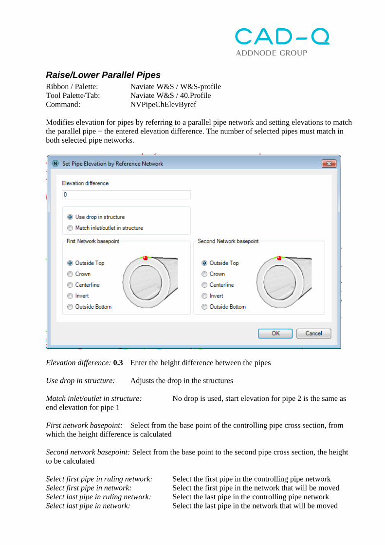
Raise/Lower Parallel Pipes Ribbon / Palette: Naviate W&S / W&S-profile Tool Palette/Tab: Naviate W&S / 40.Profile Command: NVPipeChElevByref Modifies elevation for pipes by referring to a parallel pipe network and setting elevations to match the parallel pipe + the entered elevation difference. The number of selected pipes must match in both selected pipe networks.
Elevation difference: 0.3 Enter the height difference between the pipes Use drop in structure: Adjusts the drop in the structures Match inlet/outlet in structure: No drop is used, start elevation for pipe 2 is the same as end elevation for pipe 1 First network basepoint: Select from the base point of the controlling pipe cross section, from which the height difference is calculated Second network basepoint: Select from the base point to the second pipe cross section, the height to be calculated Select first pipe in ruling network: Select the first pipe in the controlling pipe network Select first pipe in network: Select the first pipe in the network that will be moved Select last pipe in ruling network: Select the last pipe in the controlling pipe network Select last pipe in network: Select the last pipe in the network that will be moved
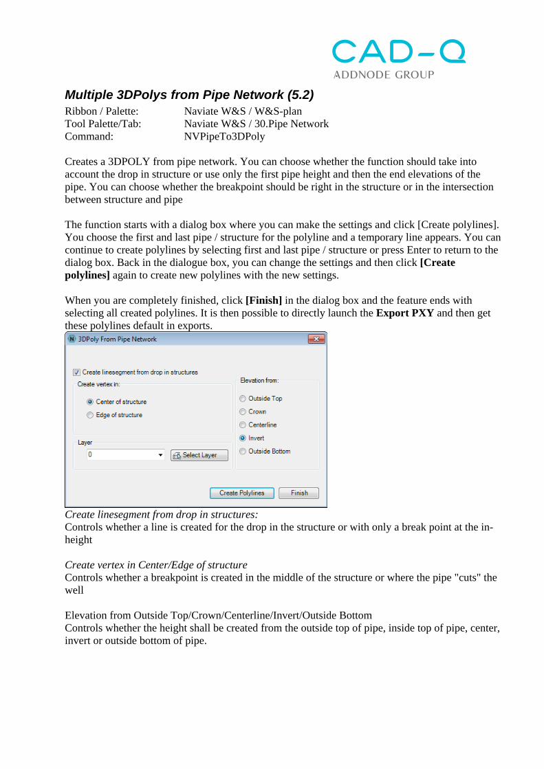
Multiple 3DPolys from Pipe Network (5.2) Ribbon / Palette: Naviate W&S / W&S-plan Tool Palette/Tab: Naviate W&S / 30.Pipe Network Command: NVPipeTo3DPoly Creates a 3DPOLY from pipe network. You can choose whether the function should take into account the drop in structure or use only the first pipe height and then the end elevations of the pipe. You can choose whether the breakpoint should be right in the structure or in the intersection between structure and pipe The function starts with a dialog box where you can make the settings and click [Create polylines]. You choose the first and last pipe / structure for the polyline and a temporary line appears. You can continue to create polylines by selecting first and last pipe / structure or press Enter to return to the dialog box. Back in the dialogue box, you can change the settings and then click [Create polylines] again to create new polylines with the new settings. When you are completely finished, click [Finish] in the dialog box and the feature ends with selecting all created polylines. It is then possible to directly launch the Export PXY and then get these polylines default in exports.
Create linesegment from drop in structures: Controls whether a line is created for the drop in the structure or with only a break point at the in-height Create vertex in Center/Edge of structure Controls whether a breakpoint is created in the middle of the structure or where the pipe "cuts" the well Elevation from Outside Top/Crown/Centerline/Invert/Outside Bottom Controls whether the height shall be created from the outside top of pipe, inside top of pipe, center, invert or outside bottom of pipe.
Dynamic 3DPoly from Network (5.2) Ribbon / Palette: Naviate W&S / W&S-plan Tool Palette/Tab: Naviate W&S / 30.Pipe Network Command: NVPlineFromNetworkParts This command creates a dynamic 3D Poly from pipes or a whole pipe network with a defined distance from the pipe in height and side. Select Entity: Choose the first and last pipe that you want to create a 3DPoly from, click Enter to continue Horizontal mode: Set if the horizontal offset distance should be calculated from the right side, left side or the center of the pipe. Vertical mode: Set if the vertical offset should be calculated from the outside top of the pipe, the crown, center, invert or outside bottom of the pipe. Horizontal offset / Vertical Offset: Set the offset values Consider drops: Set if the line should draw a vertical segment for the drop in the structure. Draw 2D polyline: Tick if the line should be drawn as a 2D Polyline, in that case you can choose a Polyline Layer Insert blocks at vertices Tick if blocks should be inserted at each node of the line. Choose what block to insert (Name), what scale (Scale) the block should have and if it should be aligned to the Polyline (Align blocks to polyline) Preview Click to see a preview OK Click to accept and end the command
Edit Dynamic 3D Poly(5.2) Ribbon / Palette: Naviate W&S / W&S-plan Tool Palette/Tab: Naviate W&S / 30.Pipe Network Command: NVPlineFromNetworkPartsEdit Use this command to edit an already created dynamic 3D Poly, it will open the same dialog box as Create Dynamic 3DPoly from Network
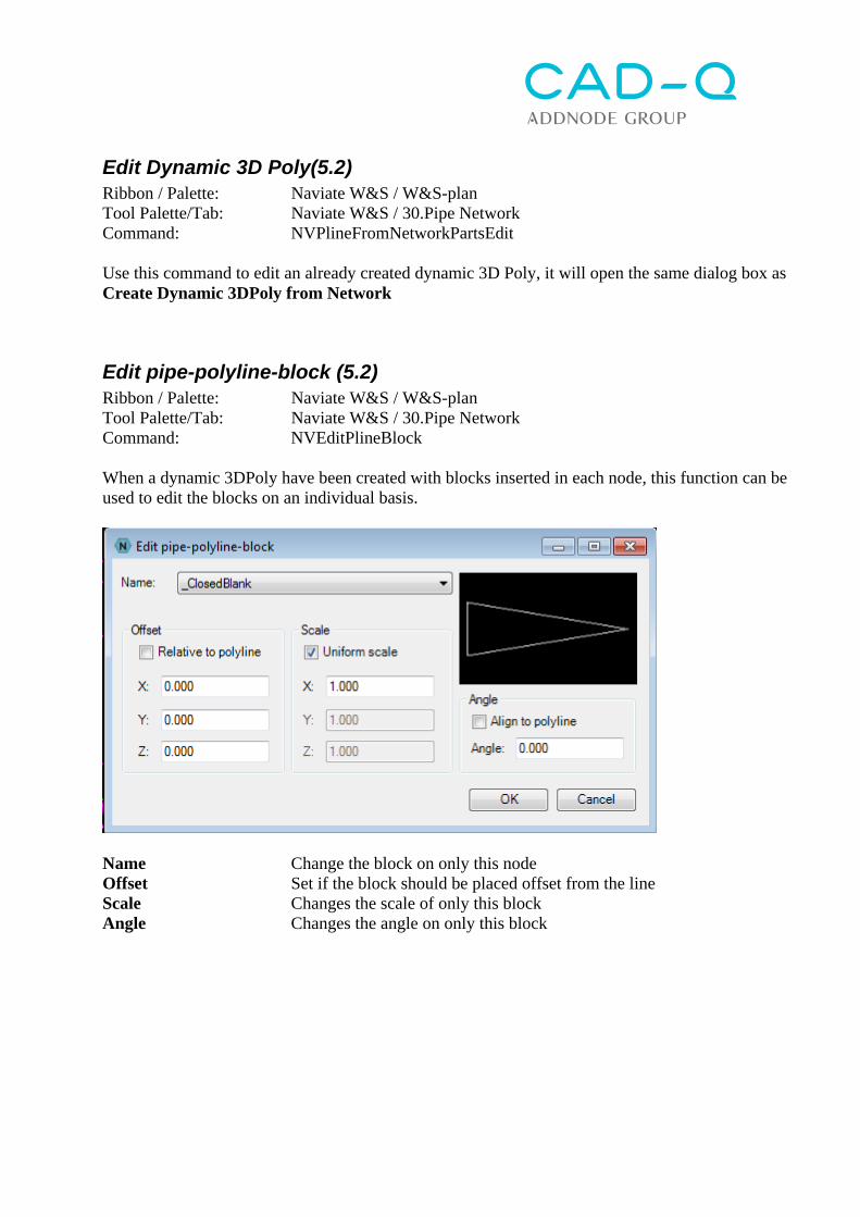
Edit pipe-polyline-block (5.2) Ribbon / Palette: Naviate W&S / W&S-plan Tool Palette/Tab: Naviate W&S / 30.Pipe Network Command: NVEditPlineBlock When a dynamic 3DPoly have been created with blocks inserted in each node, this function can be used to edit the blocks on an individual basis.
Name Change the block on only this node Offset Set if the block should be placed offset from the line Scale Changes the scale of only this block Angle Changes the angle on only this block
Create points from 3DPoly Ribbon / Palette: Naviate W&S / W&S-plan Tool Palette/Tab: Naviate W&S / 30.Pipe Network Command: CreatePtPlylnCtrvertAuto This command creates Civil 3D points, eg along the above-created 3D poly. For the command to work automatically should the Create Points dialog have the following settings:
Create points from structure Ribbon / Palette: Naviate W&S / W&S-plan Tool Palette/Tab: Naviate W&S / 30.Pipe Network Command: NVPointsFromStructure This command creates Civil 3D points from structures. The points may be created in the top, inner and outer bottom.
Tick which modes in the Structure as points to be created. For Structure top you can choose Center Frame / Structure for Frame or Structure. Point Name Suffix: Name for the item is added to the well's Name + Suffix. Create Point Group: Select a point group to be created for points as well as the name of the point group to be the same as the specified point code (Use Point Code as Name) or whether to enter the name manually (Enter Name). Point style: Select Point Style for point group. Label style: Select Label Style for point group. Filter points by Code: Select whether the point group to filter points by point code. Filter points by Number: Select whether the point group to filter points by point number. Point Code: Set point code for created points. Point LayerEnter layer that points will be created at. [Select Pipe Network]: Select pipe network where all structures to be created points off. [Select Structures]: Select the structures one by one. The function concludes by selecting all created points in the drawing. It is then possible to directly launch the Export PXY and then get those points preselected in exports.
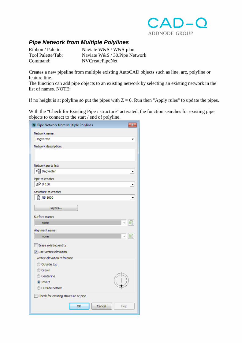
Pipe Network from Multiple Polylines Ribbon / Palette: Naviate W&S / W&S-plan Tool Palette/Tab: Naviate W&S / 30.Pipe Network Command: NVCreatePipeNet Creates a new pipeline from multiple existing AutoCAD objects such as line, arc, polyline or feature line. The function can add pipe objects to an existing network by selecting an existing network in the list of names. NOTE: If no height is at polyline so put the pipes with Z = 0. Run then "Apply rules" to update the pipes. With the "Check for Existing Pipe / structure" activated, the function searches for existing pipe objects to connect to the start / end of polyline.
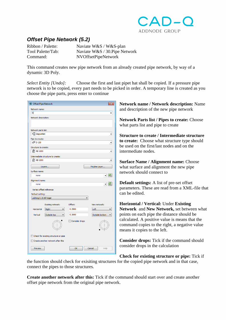
Offset Pipe Network (5.2) Ribbon / Palette: Naviate W&S / W&S-plan Tool Palette/Tab: Naviate W&S / 30.Pipe Network Command: NVOffsetPipeNetwork This command creates new pipe network from an already created pipe network, by way of a dynamic 3D Poly. Select Entity [Undo]: Choose the first and last pipet hat shall be copied. If a pressure pipe network is to be copied, every part needs to be picked in order. A temporary line is created as you choose the pipe parts, press enter to continue
Network name / Network description: Name and description of the new pipe network Network Parts list / Pipes to create: Choose what parts list and pipe to create Structure to create / Intermediate structure to create: Choose what structure type should be used on the first/last nodes and on the intermediate nodes. Surface Name / Alignment name: Choose what surface and alignment the new pipe network should connect to Default settings: A list of pre-set offset parameters. These are read from a XML-file that can be edited. Horizontal / Vertical: Under Existing Network and New Network, set between what points on each pipe the distance should be calculated. A positive value is means that the command copies to the right, a negative value means it copies to the left. Consider drops: Tick if the command should consider drops in the calculation Check for existing structure or pipe: Tick if
the function should check for exisiting structures for the copied pipe network and in that case, connect the pipes to those structures. Create another network after this: Tick if the command should start over and create another offset pipe network from the original pipe network.
Offset 3DPoly by Pipe Ribbon / Palette: Naviate W&S / W&S-plan Tool Palette/Tab: Naviate W&S / 30.Pipe Network Command: NVPipe3DPolyOffset Offsets a 3DPoly or a Feature Line by offset and elevation, adding the pipe dimensions to the offset/elevation value. The pipe dimensions can be specified manually or by selecting existing pipes. This means that the specified offset and elevation value is the horizontal/vertical distance between the pipes. With this command and function to create polylines from the pipe network, you can create new network as an "offset" of another by ultimately creating a new network using: Pipe Network From Objects Enter offset distance <0.35>: Enter offset in plan Enter offset elevation <0.3>: Enter offset in elevation Add source pipe diameter to offset [Select Source pipe] <Select Source pipe>: Enter Outer diameter for source pipe or press enter to select a pipe in the drawing Add destination pipe diameter to offset [Select Destination pipe] <Select Destination pipe>: Enter Outer diameter for destination pipe or press enter to select a pipe in the drawing Actual Offset-distance= 1.15 Actual offset distance is printed Actual Offset-elevation= 0.5 Actual elevation difference is printer Select Polyline: Choose polyline to offest Select side: Choose side to offset
Update Network by 3DPoly (5.1) Ribbon / Palette: Naviate W&S / W&S-plan Tool Palette/Tab: Naviate W&S / 30.Pipe Network Command: NVPipeUpdateFromPline Updates an existing Pipe Network by using a 3DPoly or Feature Line. Structures are move to the vertexes and the pipe elevations are adjusted by the vertex elevations. Should be used on a 3DPoly created by Naviate command: Offset 3DPoly by Pipe.
Select starting pipe: Select the first pipe
Select ending Pipe: Select the last pipe
Select Polyline or Featureline: Select a polyline in the drawing
Update Position/Elevation or Both [Position/Elevation/Both] <Both>: Position: Moves only the structure laterally and updates the pipe Elevation: Moves only pipes in height Both: Moves pipes vertically and structures laterally
Copy Alignment without arcs (5.1) Ribbon / Palette: Naviate W&S / W&S-profile Tool Palette/Tab: Naviate W&S / 80.District Heating Command: NVCopyAlignmentNoArcs Copies an alignment from a pipe network and removes all arcs. The created alignment is updated automatically if the original alignment is updated. This is used to create an Alignment from a pressure pipe network, where the alignment is created with arcs which gives the wrong length measurement for the pipe network. First create an alignment from the pipe network with Create Alignment from Pressure Network, but finish the command without clicking Create Profile and Profile View. Then use this command to create a copy, this command ends by starting the command Create Surface Profile and Create Profile View.
Update Alignment from Network Parts Ribbon / Palette: Naviate W&S / W&S-profile Tool Palette/Tab: Naviate W&S / 30.Pipe Network Command: NVPipeUpdateAligment Updates an Alignment from Network Parts, when the parts have been modified after the creation of the alignment. Must be done to update the profile view to match the network parts. The function also adds or removes breakpoints in the alignment if the number of pipes and structures have been changed. (Naviate)
Select starting pipe: Select the first pipe
Select ending Pipe: Select the last pipe
Select Alignment: Select alignment
Add missing breakpoints to alignment [Yes/No] <Yes>: If selected alignment include more vertices than the selected alignment so these are added to the selected alignment if you answer Yes.
Remove additional breakpoints from alignment [Yes/No] <Yes>: If selected alignment includes fewer breakpoints than the selected alignment will delete those away from the selected alignment if you answer Yes.
All existing curves in alignment will be removed, enter new curve radius <0.0010>: If the selected alignment contains arcs the function must delete them during the operation. Enter the new radius which then is inserted between each straight line or enter 0 (zero) to not incorporate no radius.
Create Connection Point Ribbon / Palette: Naviate W&S / W&S-plan Tool Palette/Tab: Naviate W&S / 30.Pipe Network Command: (NVAddNetworkPartPlanLabel "Servispunkt-NV" "Visa inte - etiketter") Creates a connection point on the main pipe. The connections point is a Pipe Label which is inserted in the pipe middle but can be dragged to the desired position. To connect a service pipe to the connection point use Naviate function Connect Pipe to Service Point. (Naviate)
Edit Connection Point Label Text Ribbon / Palette: Naviate W&S / W&S-plan Tool Palette/Tab: Naviate W&S / 30.Pipe Network Command: EditLabelText Edits the text for a selected connection point label. (Edit Label Text)
Connect Pipe to Connection Point Ribbon / Palette: Naviate W&S / W&S-plan Tool Palette/Tab: Naviate W&S / 30.Pipe Network Command: NVPipeConnect Connects an existing service pipe to a connection point. The pipe can be connected to any pipe label but NV-ServicePoint is recommended. Select the pipe nearest point to be connected to the service point because the feature checks which point (start or end of pipe) that is closest to the selected point.
When adjusting/connecting the service pipe to the main pipe, you can choose to retain either the service pipe slope (the opposite endpoint elevation changes) or to retain the opposite endpoint elevation (the slope changes). This choice is stored on the service pipe so that when updating the pipe using Update service pipe, you can choose "Default" setting.
Select Pipe: Select the service pipe near the end point to be connected to the main pipe
Select Label: Select Connection Point label.
Enter elevation justification [Crown/centerLine/Invert/Top-offset] <centerLine>: Crown: Crown (pipe inside top) is connected to crown of the main pipe centerLine: Center is connected to center of the main pipe Invert: Invert (pipe inside bottom) is connected to invert of the main pipe Top-offset: Outer pipe bottom is connected to the outer top of main pipe plus a specified height difference (Top-offset)
Hold Slope or Endpoint Elevation [Slope/Elevation] <Slope>: Slope: Holds service pipe slope, opposite endpoint elevation changes at update Elevation: Holds the opposite endpoint elevation, slope changes at update
Finally, the function prints the implemented settings:
Connection: Servis 1-2 Connection Point: 72827.4853,97095.4063,142.3498 Elevation justification: Crown Slope justification: Hold Slope Connected to: Ledning (8)
Update Service Pipe Ribbon / Palette: Naviate W&S / W&S-plan Tool Palette/Tab: Naviate W&S / 30.Pipe Network Command: NVPipeConnectUpdate Updates existing Service Pipes after the connection point or the main pipe has been modified. The function can perform the update of Single service pipes, all service pipes in a network or service pipes in the entire drawing (All). You can select how to update the service pipes by holding the slope, elevation or the default value set at creation of the service pipes.
Object from Pipe Network (6.1) Ribbon / Palette: Naviate W&S / W&S-plan Tool Palette/Tab: Naviate W&S / 30.Pipe Network Command: NVPipeNetworkToDWG Creates 2D (Lines and blocks) or 3d-objects (solids) från pipes and structures and copies any Naviate Properties onto the created objects. Naviate Properties can be viewed under Extended Data on the Properties Palette.
Select Pipe Network Objects: Choose what pipe objects should be exported.
Export selected networks or selected objects Choose if only the selected objects or if the whole network should be exported
Export 2D or 3D mode Choose if 2D (lines and blocks) or 3D (solids) shoul be exported
Export objects to new dwg Choose if the objects should be exported to a new DWG
Erase objects after export Choose if the created objects should be deleted after the export
Finally choose where the new DWG should be saved.
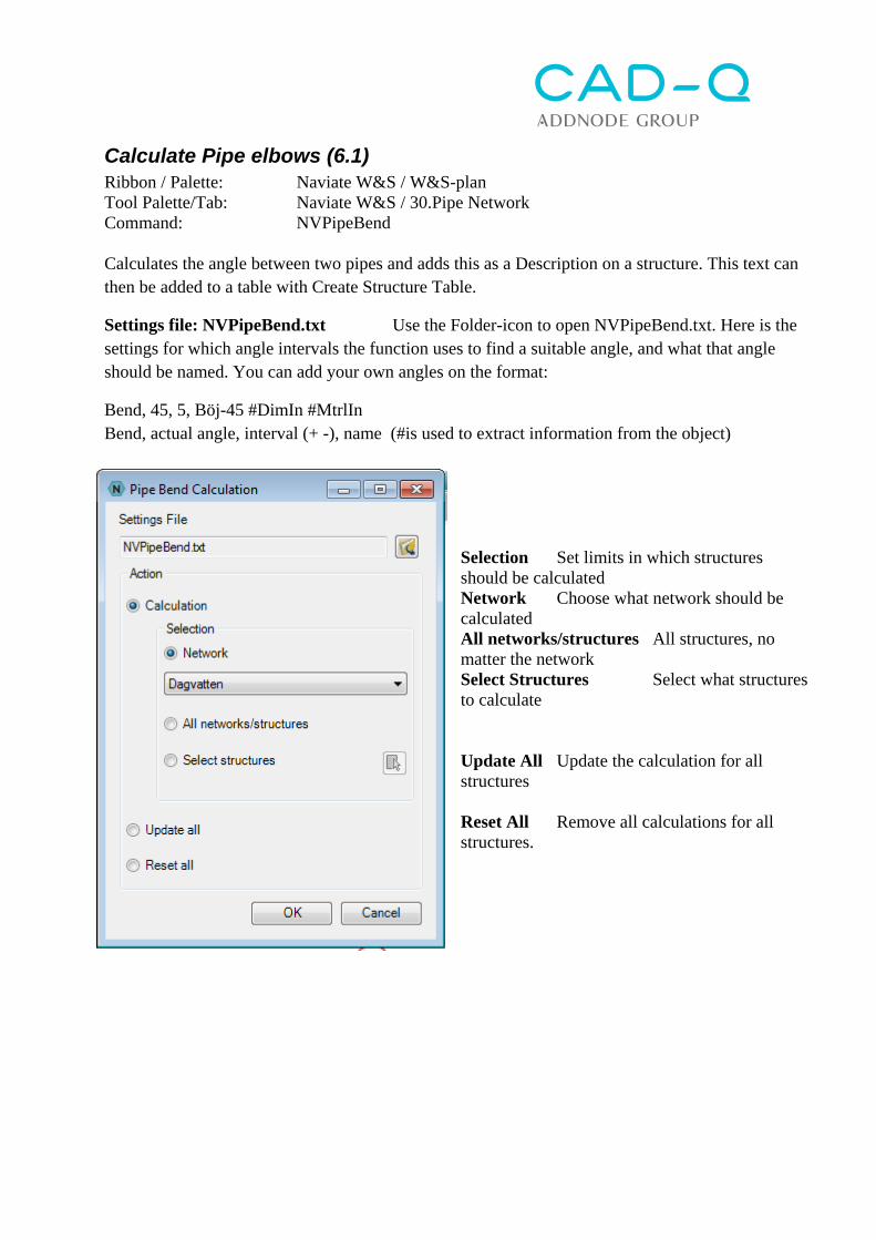
Calculate Pipe elbows (6.1) Ribbon / Palette: Naviate W&S / W&S-plan Tool Palette/Tab: Naviate W&S / 30.Pipe Network Command: NVPipeBend Calculates the angle between two pipes and adds this as a Description on a structure. This text can then be added to a table with Create Structure Table.
Settings file: NVPipeBend.txt Use the Folder-icon to open NVPipeBend.txt. Here is the settings for which angle intervals the function uses to find a suitable angle, and what that angle should be named. You can add your own angles on the format:
Bend, 45, 5, Böj-45 #DimIn #MtrlIn Bend, actual angle, interval (+ -), name (#is used to extract information from the object)
Selection Set limits in which structures should be calculated Network Choose what network should be calculated All networks/structures All structures, no matter the network Select Structures Select what structures to calculate Update All Update the calculation for all structures Reset All Remove all calculations for all structures.
Subassembly: Pipe Trench - Soil cut (6.1) Ribbon / Palette: Naviate W&S / W&S-section Tool Palette/Tab: Naviate W&S / 50.Section Command: Insert > NV-VA-Schakt-SWE.dwg Places an assembly with a Trench-subassembly. This subassembly handles only soil excavation. At insertion the AutoCAD Properties window opens. At the bottom of this window you can make settings for the subassembly.
* This shape is created for pipes with diameter> MinPipeDiameter. The volume calculation reports volumes separately and the fill volume is not adjusted for this volume. The user must manually subtract the volume of pipes from the fill volume. Points in the assembly become feature lines in the trench corridor. Links become surfaces. Shapes become volumes.
Side, right or left does not matter Actual bottom width (can be used by other subass.) Area for backfill (used by Simple Trench Calc.) Area for bedding (used by Simple Trench Calc.) Area for insulation (used by Simple Trench Calc.) Code of intersection between trench+ground (point) Slope of left trench side (2=slope 2:1 Slope of right trench side (2=slope 2:1) Code for the remaining backfill (shape + top-link) Code for Insulation (link and shape) Thickness of insulation above the backfill Code for Geotextile (link) Overlap of the geotextile (additional length) Code of backfill (link and shape) Transition slope of backfill Default width of trench floor (used by Simp.Trench) Default height of trench (used by Simple Trench Ca.) Minimum backfill above pipes Minimum backfill to trench side Calc. MinCoverSide from pipe bottom Y/N Code for pipe (shape)* Default pipe diameter (used by Simple Trench Calc.) Minimum pipe diameter for pipe shape creation * Code for bedding (link and shape) Bedding depth 15 cm Minimum bottom width of the upper bedding edge Extra widening on left side Extra widening on right side Code of bottom outer points Code of the trench sides and bottom (link) Correct with additional section width breakpoints
Then click on the assembly-pipe to place the excavation there. Finish with Esc.
Place the cursor over one of shapes (the colored areas) to see description of it.
Select the subassembly in the drawing and in the Properties-window (right-click) change various settings and note the changes in the subassembly. Please zoom in pipes in the floor plan. To create a pipe moat: I Naviate W&S > W&S-Sektion select Create corridor Select an Alignment: Press Enter and select alignmenten for the profile drawing. Select a Profile: Press Enter and select soil profile (does not really matter what) Select an assembly: Press Enter and select W&S-Schakt SurfaceTarget select e.g.. Existing lground. This indicates that the W&S trench edges should go up to the parking area, not to existing land. Width or Offset Targets - PipeNetwork1 Select e.g.. Storm sewer. Width or Offset Targets - PipeNetwork2 Select e.g.. Sanitary sewer. Width or Offset Targets - PipeNetwork3 Select e.g.. water What order to choose the pipe network does not matter. Width or Offset Targets - TrenchBeddingOffsetLeft select e.g.. a polyline or feature line to control the left edge of the pipe bed / shafts, such as width change around a structure. Note that there are functions to export the polylines from the corridor, Create Feature Lines From Corridor or Create polylines From Corridor.Width or Offset Targets - TrenchBeddingOffsetRight select e.g.. a polyline or feature line to control the right edge of the pipe bed/trench. Slope or Elevation Targets - TrenchBeddingElevation select e.g.. a polyline, feature line or profile to guide the lower edge of the pipe bed / trench Click OK.
The shafts will now have a default density of the sections, for example 5m. To change this, use the Naviate W&S > W&S-Section > Change interval for corridor
Here you can change the density. Note that the option "At horizontal geometry points" control sections to be created in each breakpoint = structure. Click OK.
Insert curve in alignment Ribbon / Palette: Naviate W&S / W&S-Section Tool Palette/Tab: Naviate W&S / 50.Section Command: NVAlignFillet If the assembly frequency is too small, the sections will cross each other in the inside corners of the corridor.
To get a better curve, first use Insert curve in alignment, the command is preset with a radie of 0.001, that is enough to get a better curve.
Edit corridor region frequency Ribbon / Palette: Naviate W&S / W&S-section Tool Palette/Tab: Naviate W&S / 50.Section Command: Edit CorrregionFreq To fix the crossed sections, use Edit corridor region frequency. Set all values to 100 and to No, then click the plus-button to add your own sections. To place the sections at suitable locations in the corridor, use the function Set frequency by Alignment breakpoints byt typing ’NVSTA on the commandline Select Alignment: Chose the alignment Enter interval: 2 (2 meters between each section) Min distance to vertex: 2 (no sections closer than 2 meters to each node) Click Enter
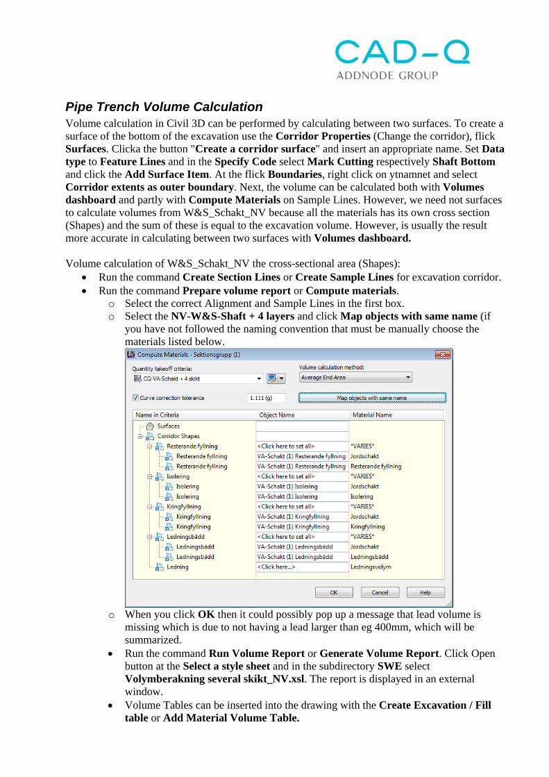
Pipe Trench Volume Calculation Volume calculation in Civil 3D can be performed by calculating between two surfaces. To create a surface of the bottom of the excavation use the Corridor Properties (Change the corridor), flick Surfaces. Clicka the button "Create a corridor surface" and insert an appropriate name. Set Data type to Feature Lines and in the Specify Code select Mark Cutting respectively Shaft Bottom and click the Add Surface Item. At the flick Boundaries, right click on ytnamnet and select Corridor extents as outer boundary. Next, the volume can be calculated both with Volumes dashboard and partly with Compute Materials on Sample Lines. However, we need not surfaces to calculate volumes from W&S_Schakt_NV because all the materials has its own cross section (Shapes) and the sum of these is equal to the excavation volume. However, is usually the result more accurate in calculating between two surfaces with Volumes dashboard. Volume calculation of W&S_Schakt_NV the cross-sectional area (Shapes):
Run the command Create Section Lines or Create Sample Lines for excavation corridor. Run the command Prepare volume report or Compute materials.
o Select the correct Alignment and Sample Lines in the first box. o Select the NV-W&S-Shaft + 4 layers and click Map objects with same name (if
you have not followed the naming convention that must be manually choose the materials listed below.
o When you click OK then it could possibly pop up a message that lead volume is
missing which is due to not having a lead larger than eg 400mm, which will be summarized.
Run the command Run Volume Report or Generate Volume Report. Click Open button at the Select a style sheet and in the subdirectory SWE select Volymberakning several skikt_NV.xsl. The report is displayed in an external window.
Volume Tables can be inserted into the drawing with the Create Excavation / Fill table or Add Material Volume Table.
Subassembly: Pipe Trench - Rock cut Ribbon / Palette: Naviate W&S / W&S-section Tool Palette/Tab: Naviate W&S / 50.Section Command: Insert > NV-W&S-Schakt-Berg-SWE.dwg Places an assembly with a Trench-subassembly, this assembly handles both soil and rock excavation. Click on the section element W&S Schakt_Berg to open the AutoCAD Properties-window. At the bottom of this window you can make settings for the section.
*This shape is created for pipes with diameter> MinPipeDiameter. The volume calculation is reported managements volume separately and on the fill volume is not adjusted for volume management. The user must then manually subtract volume for leads from around the fill volume.
Then click on the assembly line to place the excavation there. finish with Esc. Subassemblyn looks weird that's because it shows both state and non-excavated rock.
Side , right or left does not really matter Current bottom width (can be used by other subass . ) Code of intersection between land / pit ( point) Code of the intersection of the upper surface of the soil (link) Code of earth undercut cross section (shape ) Slope of jordschaktens sides : 4:1 Code for the remaining filling (shape and even top -link ) Code of the intersection of rock's top surface (link) Code for rock cut's cross section (shape ) Width of exposing the rock shelf Slope of bergschaktens sides : 5:1 Code for Insulation (link and shape ) Thickness of insulation above the backfill Code for Geotextile (link) Code of backfill (link and shape ) Gradient stair none in surrounding backfill above the edge Minimum backfill conduction Minimum backfill at the side of management My ledningsdim to conductor size / shape calculated * Code of the line ( shape ) * Code for a bedding (link and shape ) Ledningsbäddens depth 15 cm Minimum bottom width of the upper edge ledningsbäddens Code for strengthened management bed in the middle (link and shape ) Enhanced ledningsbädds depth of 10 cm
Target Mapping i Corridor Properties:
ExistingSurfaceTarget select e.g.. Befintlig markThe terrain model as the W&S trench edges to go up to. RockSurfaceTarget select e.g.. Bergyta. The terrain model W&S-shafts to check for rock cutting. If the bedding is under the rock surface so goes hillsides first up to the rock surface with a slope RockCutSideSlope, followed by the rock surface out with distance RockBenchWidth. Then it goes up to the surface with the slope ExistingGroundSideSlope. Width or Offset Targets - PipeNetwork1 select e.g.. Storm sewer. Width or Offset Targets - PipeNetwork2 seclet e.g.. Sanitary sewer. Width or Offset Targets - PipeNetwork3 select e.g.. sewer What order to choose the grids does not matter. Width or Offset Targets - TrenchBeddingOffsetLeft select e.g.. a polyline or feature line to control the left edge of the pipe bed / trench, such width change around a well. Note that there are functions to export the polylines from the corridor, Create Feature Lines From Corridor or Create polylines From Corridor. Width or Offset Targets - TrenchBeddingOffsetRight select e.g.. a polyline or feature line to control the right edge of the pipe bed / trench. Slope or Elevation Targets - TrenchBeddingElevation select e.g.. a polyline, feature line or profile to guide the lower edge of the pipe bed / trench.
VA Schakt_Trappa (subassembly) (6.1) Ribbon / Palette: Naviate VA / VA-Sektion Tool Palette/Tab: Naviate VA / 50. VA-sektion Command: Insert > NV-VA-SchaktTrappa-SWE.dwg Placerar en assembly med ett VA-schakt/sektionselement (subassembly). Denna VA-schakt anpassar sig efter trappade ledningar. Klicka på sektionselementet VA-Schakt_Trappad så öppnas AutoCADs Properties-fönster. Nederst i detta fönster kan man göra inställningar för sektionen.
Sida, höger eller vänster spelar egentligen ingen roll Aktuell bottenbredd (kan användas av andra subass.) Area för kringfyllning (anv. av Enkel Schakt) Area för ledningsbädd (anv. av Enkel Schakt) Arear för isolering (anv. av Enkel Schakt) Kod för skärningspunkt mellan mark/schakt (point) Lutning på vänster schaktsida: (2= lutning 2:1) Lutning för höger schaktsida (2=lutning 2:1) Kod för resterande fyllning (shape och även topp-link) Kod för Isolering (link och shape) Välj isoleringsmetod ** Tjocklek för isolering ovanför kringfyllningen Bredd för isolering (om metod 1 är vald) Minsta täckning för om isolering ska skapas Kod för Geotextil (link) Överlapp för geotextil (omvikslängd) Kod för kringfyllning (link och shape) Lutning för trappningen i kringfyllningens ovankant Standard täckning över ledningar Standard bredd (anv. av Enkel Schakt) Standard höjd (anv. av Enkel Schakt) Minsta kringfyllning över ledning Minsta kringfyllning vid sida om ledning Beräkna MinCoverSide från UK ledning Kod för ledning (shape)* Standard ledningsdim (anv. av Enkel Schakt) Min ledningsdim för att ledningsarea/shape beräknas* Kod för ledningsbädd (link och shape) Ledningsbädd Minsta bottenbredd för ledningsbäddens ovankant Extra breddning av botten på vänster sida Extra breddning av botten på höger sida Kod för bottens yttre punkter (point) Använd trappad bottenyta Kod för schaktens sidor och botten (link) Korrigera med extra sektionsbredd i brytpunkter
* Denna shape skapas för ledningar med diameter > MinPipeDiameter. I volymberäkningen redovisas ledningarnas volym separat och kringfyllningens volym är inte justerad för ledningsvolymen. Användaren måste alltså manuellt subtrahera volym för ledningar från kringfyllningens volym. ** Isoleringsmetoder 1 Individuell isolering 2 Rak isolering över alla ledningar 3 Isolering över alla ledningar, följer kringfyllningens övre linje
Simple Trench (6.1) Ribbon / Palette: Naviate W&S / W&S-section Tool Palette/Tab: Naviate W&S / 50.Section Command: NVTrench A simple trench calculations based on Naviate W&S subassembly that is stored in Naviate Properties on the pipes. By making changes in the Property Set you can decide what to to calculate. First place a Naviate W&S subassembly and change the settings in Properties. Start the command Simple Trench. Select Pipe: Select a pipe Select next pipe part or [all pipes in Network] Select more pipes, or choose the whole network Select Subassembly: Select the subassembly Select Property set [[1]VA-schakt] Select the Property Set to use (VA-schakt is preset) Do you wish to view Property Data? When the calculation is done you can choose to view the result in the Naviate Properties.
Create Table (6.1) Ribbon / Palette: Naviate W&S / W&S-section Tool Palette/Tab: Naviate W&S / 50. Section Command: NVPropertyTable Use the Create Table command to produce a table of the trench. See Create Table in Naviate Palettes.
District heating (4.2) Functions for managing district heating (Pressure Pipes) Pressure pipe contain the following object types:
Pressure Pipes: Pipes type straight pipe, curved pipes and Zebra pipes
Fittings: Elbows, T-pieces, reduction pipes, connection bend etc.
Appurtenance: valves, venting/draining, etc. Pressure Network Catalog
A catalog file of available Pipes, Fittings and Appurtenance. In Naviate is a catalog file (Powerpipe_enkelror_serie2.sqlite) with a large selection from Power Pipe Single pipe League second
Pressure Network parts list A list with a selection of available Pipes, Fittings and Appurtenance in selected catalog file (Pressure network catalog). Eg all bends Power Pipe Series 2nd
Most functions in the palette are translated standard features in Civil 3D. Start with Select pipe catalog and select correct pipe network catalog. To create a new pipe networkis used e.g. Drawing grids (Pressure Network Creation Tools) or Create grids from lines (Create Pressure Network from Object). These commands, and many more, are contained in Civil 3D's Home-ribbon. When a pipe network is drawn in plan create a profile drawing, and soil profiles, with Create profile drawing from the grid. In Bands tab in the dialog box Create Profile View, select Band set for FJV-Profile Divided - NV for conduction band for district heating in the profile drawing. Unfortunately does not support Civil 3D's Profile Bands, Pressure Pipe Networks but only "ordinary Pipe Networks. Therefore, choose grids Tom for not getting something completed in the bands. After the profile drawing created , you can insert definitions :
Management Designation in profile Mark a line so translated materials , dim , tilt and height out of all the lines. Select all the labels , right click and select Label Properties and in the Properties pane ways Dimensional Anchor Value to -62 . Highlight a label , grab the square grip , pull lablen down to the diamond-shaped grip that will produce text right . The change of Dimensional Anchor Value of -62 means that the diamond-shaped grip ports 62mm in drawing the bottom so that you can more easily draw the text right .
Length measurement Designation in profile Mark a line so is the length measurement in all lines. Highlight a label , grab the square grip and pull lablen down to the diamond-shaped grip that will produce text right .
Balloon marks for bend in the profile
Highlight a bend or device so placed balloons with the object name submitted. Type name for the bend in the profile
Highlight a bend or device so placed the object's type designation under the balloon.
Create 3DPOLY from pipe network (4.2) Creates a 3DPOLY from pipe network . First choose if polylinen be drawn for Invert (water walking ) , Center, Top or Bottom . Point out the direction for pipe and bends, T-pieces in chronological order. The created polylinen can parallel copied using the Parallel Copy polyline via pipe to then create eg a parallel returnät with Creating pipe network from the lines. Polylinen can also be used for restocking with Export to PXY . The polyline can also be used to "snap on" if you need to draw the pipe network with a new dimension. Unfortunately lacks the Civil 3D function to change dimension of created pipes .
Points from Polyline (4.2) Ribbon / Palette: Tool Palette/Tab: Naviate W&S / 80.District Heating Command: NVEchoPointsFromPline Reads an existing polyline and sends the coordinates to the function is active. The operation is transparent then run it inside another command , such as Create a pipe network .
Divide the distance in points (4.2) Ribbon / Palette: Tool Palette/Tab: Naviate W&S / 80.District Heating Command: NVEchoDividedPoints Divides the distance between the two points to several sub-items in any interval and sends the coordinates to the function is active. The operation is transparent then run it inside another command , such as Create grids . It can then e.g. divide a distance of 100m at intervals of 12 meters pipe .
Naviate Road (5.1) Naviate Road contains the following tabs:
Alignment - Management Features: Alignment o Superelevation o Intersection o Tables
Profile - Management Features and sectional (Profile View) o Profile o Profile View
Section - Management Features:Assembly o Corridor o Section View o Quantity take off
Layer - Ability to turn on / off layers and change the color of layers Swept Path - Blocks for vehicle tracking for standard vehicle
Naviate Road Ribbon includes the following features:
Line codes, Link codes and Shape codes for corridor (4.2) Ribbon / Palette: Naviate Road / Road Tool Palette/Tab: Naviate Road / 50. Section Command: se nedan Three features that work the same way but with different object types. Line Codes for corridor Creates line styles in the Code Set Style for a corridor by creating line styles from point codes in a subassembly. Command: NVCODESETSTYLEADDPOINTCODE Link Codes for corridor Creates link codes and styles in the Code Set Style for a corridor by creating Link styles and Surface styles from link tags in a subassembly. Command: NVCODESETSTYLEADDLINKCODE Shape Codes for corridor Creates shape codes and types in the Code Set Style for a corridor by creating Shape styles from shape codes in a subassembly. Command: NVCODESETSTYLEADDSHAPECODE Since Naviate subassemblies are able to have their own point codes, this feature creates settings in a Code set style, to use those codes. This function creates styles for Points in the selected code set style and also creates a Feature line style with the same name as the point code. When creating Feature line style, you have the choice to add prefix, suffix and interfix to the layer name.
Code Set Style: Select the Code Set Style in which the codes should be created. Prefix: Enter the characters that each layer name should begin with. Code starting character: Specify from which character in the point code the text should be retrieved. Number of character: Specify the number of characters in the point code to be retrieved. Can be 0! Interfix: Characters that are added in the middle of the layer name. Code starting character: Specify from which character in point code the text should be retrieved. Number of character: Specify the number of characters in the point code to be retrieved. Can be 0! Suffix: Characters added to the end of the layer name. [Import]: Click Import and then select the subassemblies in the drawing.
Now you get a list with all the point codes that will be added. Here you can make changes to each point code, as well as right click to remove a code. At the bottom, you can check the Add Pay Item ID 's which means that pay Item ID 's will be added to each code. Pay Item Id prefix is used to put a prefix on the pay item code in the file and a recommendation is to use M1- for point codes and M2- for link codes. If a Pay Item Code is missing in the current Pay Item File, the following display appears with the question if these codes should be added to the Pay Item file (the original file is backed up). If you click OK then the next window states that you have to "force" Civil 3D to load the new codes by in the QTO Manager click Open Pay Item File and then directly OK (so it reads the same file again), after that the QTO Manager opens automatically. After having read in the Pay Item file again, you have to run the command to connect the Pay Items to codes.
There is a problem if you use old files created in earlier versions of Civil 3D, which then points to an old Pay Item File, which the command notifies via an info window. The only way to redirect this is to go into the QTO-manager and select Open Pay Item File. This takes Civil 3D automatically to the latest version and you HAVE TO click OK for this to be stored, otherwise it still points to the old file!
Import Corridor Codes from File (5.2) Ribbon / Palette: Naviate Road / Road Tool Palette/Tab: Naviate Road / 50. Section Command: NVCodeSetStyleAddCodes Imports settings for line-, link-, and shape-codes to one or more Code Set Styles, from a text file with settings for each code. The function also creates styles for Featurelines, Links and Shapes for each code. The text file can contain the following columns: Code Set Style;Type;Code;Prefix;Start character;No characters;Plan Interfix;Model Interfix;Profile Interfix;Section Interfix;Start character;No characters;Suffix;Description;Color;Linetype;Lineweight;Description OBS! For a Code Set Style, multiple styles can be set with a ”,” between. ”*” means that the code should be added to all Code Set Styles in the drawing. All columns from Color are for the layer and are optional. See below for an example
Check Subassembly codes (5.2) Ribbon / Palette: Naviate Road / Road Tool Palette/Tab: Naviate Road / 50. Section Command: NVCodeSetStyleCheckCode Checks that all codes for Point, Link and Shape in selected subasembly are listed in selected Code Set Style. Faulty codes are displayed in a list and can be changed or added to selected Code Set style. Workflow: Choose Code Set Style, click on Select subassembly and choose one or more subassemblies in the drawing. Then click Show after all Subassemblies checked. In the second box a list of all codes that are in use but is not in the code set style is now displayed. The same code can show up on multiple rows if the code has been used in multiple places. Right click in the list to do the following:
Select subassembly: Selects the subassembly in the drawing, for instance to view the subassembly in Properties
Zoom to subassembly: Zooms to the subassembly in the drawing Edit Code in subassembly: Edits the codes in the subassembly Add Code to Code Set Style: Adds the code to the Code Set Style
At the bottom you find the current codes in the Code Set style, these can be copied by right-clicking on them and then pasted on the subassembly with Edit Code in subassembly.
The three remaining buttons at the top lets you run the function on one subassembly at a time. Break at first subassembly with wrong code: Stops the function at the first subassembly with a faulty code Continue with next subassembly: Move on to the next subassembly Rerun last subassembly: Run the command on the last subassembly, to check changes just made.
Find and Replace Corridor Codes (6.1) Ribbon / Palette: Naviate Road / Road Tool Palette/Tab: Naviate Road / 50. Section Command: NVSubassTextReplace Searches for codes in selected subassemblies and replaces them with a new code. Select objects to list: choose one or more subassemblies
Parameter name Choose what type of code the function should search for, choose All to search in all codes Search Text Set what text should be searched for Replace Text Set what text should replace the old Match case Tick if the function have to match case Match whole word Tick if the function only can replace whole words Click Replace to run the command. You get a list in the box of the changes made. Click Close to exit the command.
Solids from corridor (5.1) Ribbon / Palette: Naviate Road / Road Tool Palette/Tab: Naviate Road / 50. Section Command: NVCorShapeToSolid Creates solids from a corridor cross section (shapes). Solids can either be created on a layer that has the same name as the shape but you can also specify the prefix and suffix for the layer name (PrefixShapecodeSuffix). If the layer does not exist, the command creates the layer with a color that is the same as the shape. The solids can also be created on the same layer as the Model layer of the shapes style. This style/layer can be generated with Naviates function Shape Codes for corridor. Select Corridor: Choose corridor in the drawing Shape Code <4.1>: Enter the shape code or press Enter to use all codes Segment Intervall <0>: Enter the interval for solid generation. 0 (zero) means that the solid is created from the corridor start to finish. 1 means that every solid is built by one segment between two sections of the corridor. 2 means that the solid is built by two segments, etc.. Layer name by Shape Code or Shape Layer name [Shapecode/Layername] <Shapecode>: S Layer prefix < >: Enter the start character for the layer name for the solid. The text is added before the name of shape in the corridor. Valid only if Shapecode is used. Layer suffix <>: Enter the ending character of the layer name for the solid. The text is added after the name of the shape in the corridor. Valid only if Shapecode is used. The command ends with all the created solids being selected, so that you can directly start another command, such as Object Viewer or WBlock. The command also adds Naviate Properties (Code, layer, station, volume, area etc) on each solid. The Property set is created automatically but can be edited afterwards, and for instance add more information.
Lines / Surfaces from Corridor (5.1) Ribbon / Palette: Naviate Road / Road Tool Palette/Tab: Naviate Road / 50. Section Command: NVCorPXY Export selected lines/surfaces from a corridor to a PXY-file (or to lines in the DWG). Se more at Export corridor > PXY
Solid from surface(5.2) Ribbon / Palette: Naviate Road / Road Tool Palette/Tab: Naviate Road / 50. Section Command: NVSolidFromTinSurface Creates solids from 3DFaces in a surface to an set reference height. The selected surface has to have a surface style that displays the triangles. The command returns the surface max and min elevation and at Extrude value you enter a value that has to be lower than the min elevation or higher than max elevation.
Cut/Fill-solids from Surfaces (5.2) Ribbon / Palette: Naviate Road / Road Tool Palette/Tab: Naviate Road / 50. Section Command: NVCutfillSolidFromSurfaces Creates solids for cut and fill between two surfaces and divides them along an alignment at a set interval. The command also adds Naviate Properties, such as volume, station value, area etc. on the solids. The solids can be connected to an Alignment and/or a corridor. Hint! The command can take a long time if you have a large surface and it is therefor recommended that you limit the surface to the corridor. You can use Extract Objects to extract the boundary of the corridors terras surface. Convert this line to a 2DPolyline (Convert3dPolys) and offset it a suitable distance away from the corridor. Then add the line to the surface as a Boundary. Select Base Surface: Select the new road surface Select Ground Surface: Select the existing ground surface Select Alignment [No Alignment]: Choose an Alignment to retrieve station value, offset value etc. from Select Corridor [No Corridor]: Choose a corridor to connect the solids to. Start Station <0.0000>: Set start station value End Station <300.0000>: Set end station value Interval[0 = no split] <20.0000>: Set an interval for the division of the solids Cut Layer <_Cut>: Set the layer for the Cut solids Fill Layer <_Fill>: Set the layer for the Fill solids
Select objects from corridor (5.2) Ribbon / Palette: Naviate Road / Road Tool Palette/Tab: Naviate Road / 50. Section Command: NVSelectObjectFromCorridor Selects all solids, lines and 3D Faces that have been extracted from one or more corridors. This command is to easily find these objects to export, delete och change the properties of the objects. You can choose if you want to select solids, lines and/or 3D Faces. In AutoCAD Properties palette there is an option for solids to change Surface Normals to for instance Smooth to get smoother solids.
Compute All Materials Ribbon / Palette: Naviate Road / Road Tool Palette/Tab: Naviate Road / 50. Section Command: NVComputeMaterial Creates a Quantity Takeoff Criteria for all used shape codes in a corridor. The created criteria can then be applied on Sample Lines to perform a volume calculation. Since Naviate subassemblies are able to set their own codes for shapes / cross sections, so creating this feature settings in a volume calculation criterion, Quantity TakeOff Criteria, for the use of the codes. This function searches the selected corridor by using the Shape Codes and post these in a volume calculation criterion, Quantity TakeOff Criteria. One must first address the possibility to specify the name of the criterion. You can also choose if you want to start from an existing criterion. You get info about the man himself must choose this criterion if you already put on a criterion of selected Sample Lines
Then click on Map objects with same name.
After that, drive mode Run volume report / Generate Volume Report NOTE! Internet Explorer 9 is not capable of running reports with AAO in the report name. Therefore you have to rename the Swedish report template!
Add Feature Line Labels Ribbon / Palette: Naviate Road / Road Tool Palette/Tab: Naviate Road / 50. Section Command: AddSegmentLabels Creates description texts / labels for the height of each vertex on an F-line (feature line). The style of the label is the default or last used. More opportunities, see "Creating description text." (Add Segment Labels)
Edit Label Frequency Ribbon / Palette: Naviate Road / Road Tool Palette/Tab: Naviate Road / 50. Section Command: NVremoveSegmentLabels Edits label frequency by removing labels that do not match entered interval. The labels must first be inserted using “Add Feature Line Labels”. Command: NVREMOVESEGMENTLABELS Select [Corridor/Feature Line] <Corridor>: Enter C for all created feature lines from a corridor or F to select feature lines one by one. Select Corridor / Select Feature Line: Choose corridor feature lines in the drawing Select Alignment: Select the alignment of the drawing Set C/C Interval <20.0000>: Enter the range of labels/labels that are retained Set Tolerance <0.0010>: Enter tolerance in mm for how much text may deviate from the exact length measurement to be interpreted correctly.
Elevation labels along an Alignment (4.2) Ribbon / Palette: Naviate Road / Road Tool Palette/Tab: Naviate Road / 50. Section Command: AddAlignOffLbl Adds Surface Elevation labels along an Alignment at entered stations. (Naviate)
Interval and offset for labels (4.2) Ribbon / Palette: Naviate Road / Road Tool Palette/Tab: Naviate Road / 50. Section Command: NVEchoStationOffset This transparent command sends an interval of station and offsets to the active label command (e.g. “Add Elevation labels along an Alignment”). If the label contains a Surface Elevation component, the first label must be inserted so the reference Surface can be selected, before this command is selected. (Naviate)
Create bus stop (6.1) Ribbon / Palette: Naviate Road / Road Tool Palette/Tab: Naviate Road / 30. Alignment Command: NVWidening Creates a widening after a pre-set template. The templates can be found in NVWidening.xml. The widening is created in an exisiting offset alignment First select the aligment. In the dialog box, you find the different templates for widening. Click on Add Widening to set where the widening should start.
Edit bus stop (6.1) Ribbon / Palette: Naviate Road / Road Tool Palette/Tab: Naviate Road / 50. Section Command: OffsetParameters Opens the Civil 3D Offset Alignment Parameters dialog box. Choose the alignment and the widening and make changes direct in the dialog box.
Create Curb Return (5.1) Ribbon / Palette: Naviate Road / Road Tool Palette/Tab: Naviate Road / 30. Alignment Command: NV_TR_Tractrix Creates an intersection curve (Alignment or Polyline) between two road boarders. The curve is dynamic and automatically updated if you change the border lines (Polyline or Alignment). The function may create intersection curve with one, two or three radius. Enter radius and lengths
according to the figure. Click Select entry / exit road edge to select border line for incoming and outgoing road. Draw as: Select whether the intersection curve is created as an Alignment or Polyline. Layer: Select the layer for the lines For Alignment, Site, name, style and label set can be selected. At Alignment is a button to select an existing alignment in the drawing. This prints line data into this and replaces the existing line data in the selected alignment. This is useful for existing Curb return Alignments created by Civil 3D's Intersection tool. However, one must erase the Intersection object to make these alignments editable. Draw hatch: Draws a grid at the intersection. Draw extension: Draws straight lines at the beginning and end along selected border lines.
Create Bridge Columns (4.2) Ribbon / Palette: Naviate Road / Road Tool Palette/Tab: Naviate Road & Landscape / 80. Visualization Command: NVColumn Creates Bridge Columns, from inserted labels along an Alignment. The label must contain components for Bottom-2D-Block, Bottom-3D-Block, Bottom-Surface-Elevation, Top-2D-Block, Top-3D-Block, Top-Surface-Elevation. The function searches for Alignment Station / Offset label, with the indicated components. It inserts bottom-3D Block and Bottom-2D Block in the labels XY point but with Z from bottom-Surface Elevation. It inserts Top-3D Block and Top-2D Blocks, in the labels XY point but with Z of Top-Surface-Elevation. It then creates a solid via a loft between bottom-2D Block and Top-2D Block. Then the command combines all solids together to one Solid. If there is a value in the field Render Material in the label, the command also applies a Render Material.
These labels automatically moves with the Alignment. The solids can be updated via this function.
[Create/Update] <Create>: Select Create to create new, or Update to update existing columns. [Single/Multiple] <Single>: S Select Single to select one single label or Multiple labels to select
an alignment and therefore all its labels.
Insert Bridge Column Label (4.2) Ribbon / Palette: Naviate Road / Road Tool Palette/Tab: Naviate Road & Landscape / 80. Visualization Command: AddAlignOffLbl Inserts Naviate standard-label for Bridge Columns, at entered station/offset values along an Alignment.
3D-Measure (4.2) Ribbon / Palette: Naviate Road / Road Tool Palette/Tab: Naviate Road & Landscape / 80. Visualization Command: NVMeasure Places 3D objects (eg lampposts) along a line. See the same command in Naviate Landscape.
Naviate Traffic/Autopath (5.1) The palette contains functions for:
Road signs Intersection Markings such as crosswalk, bicycle crossing, yield/stop, speed bumps, etc. Longitudinal marker as barrier lines, roadway lines, double lines, etc. Barring Area Turn on/off filled areas Palette with Dynamic Blocks for Location Signs. Size, text and other block types can be
selected / changed after inserting these blocks.
Ribbon tabs for Naviate Traffic and Naviate Autopath are located on Naviate Road Ribbon:
Insert traffic sign Ribbon / Palette: Naviate Road / Traffic Tool Palette/Tab: Naviate Traffic / 00.Traffic Command: NV_Tr_Signinsert_SWE Inserts a traffic sign in the drawing. Point out the location of the pole and then place the sign. Then
point out a rotation for the post and sign or press Enter to not rotate. To change post press enter before selecting location for the post. Table: Select the category of traffic signs. Symbols: Choose a traffic sign, double click to insert it directly. Otherwise specify attributes at the bottom and click OK to insert the sign. Traffic sign insertion point (current post: TR_POST-170 _A) <ENTER - select post>: Point out the location for pole icon, usually at the roadside. To change the pole for the sign itself press Enter. Traffic sign position in the drawing: Point out the location of the sign, usually in a free space at the side of the road. The sign appears with the selected post. Specify angle <0.000> or [Interactive]: Enter the rotation for post/sign or choose the Interactive for pointing out the rotation. Rotate traffic sign as well? [Yes/No] <No>: Yes rotate both the post by the roadside, and the symbol on the side. No twists only post.
Add/edit sign Ribbon / Palette: Naviate Road / Traffic Tool Palette/Tab: Naviate Traffic / 00.Traffic Command: NV_Tr_SignManager_SWE Editing an existing sign or add a sign to an existing sign / post. To add a sign, click on the "+" and select a new sign. To put it on the other side of the post click "Inv". Repeat for other signs. The pole is changed automatically.
Move sign Ribbon / Palette: Naviate Road / Traffic Tool Palette/Tab: Naviate Traffic / 00.Traffic Command: NV_Tr_SignMove_SWE Moves an existing sign to new location and rotation.
Copy sign Ribbon / Palette: Naviate Road / Traffic Tool Palette/Tab: Naviate Traffic / 00.Traffic Command: NV_Tr_SignCopy_SWE Copies an existing sign to new location and rotation.
Skapa Portal (6.1) Ribbon / Palette: Naviate Road / Traffic Tool Palette/Tab: Naviate Traffic / 00.Traffic Command: NVPortalInsert To create a traffic portal with a road sign, first you have to create a road sign and save it as a image file. Use the commands on the Traffic panel to create this.
Zoom, Object Zoom in on the road sign to export only the road sign. Measure, Distance Measure the longest side of the sign, this will be used as size when the sign is re-imported. Export Image Export the whole sign as a JPG Image, New Clip Boundary Clip the image to remove potential black borders. Image, Frame To turn off the display if imageframes, set IMAGEFRAME to 0 Start the command Traffic Portal to insert a traffic portal. Set size in the boxes and click OK when done.
Specify gantry position Set where the portal should be placed along the corridor Specify schema position Set where the side-view of the portal should be placed Select elements for new guide sign Select your road sign Specify base point Click where the basepoint on the road sign is Specify guide sign position on the gantry Click where the basepoint should be placed on the portal Is guide sign facing alignment direction [Yes/No] Set if the sign is pointing in the right direction Select elements for new guide sign Add more signs to the portal Press enter to finish the command.
Draw cross markings Ribbon / Palette: Naviate Road / Traffic Tool Palette/Tab: Naviate Traffic / 00.Traffic Command: NV_Tr_Crosslabels_SWE Creates intersection markings such as Stop line, Give Way Line. Bicycle Overpass, Crosswalk.
Draw longitudinal markings Ribbon / Palette: Naviate Road / Traffic Tool Palette/Tab: Naviate Traffic / 00.Traffic Command: NV_Tr_Longlabels_SWE Creates longitudinal line marking on alignments, polylines, or Feature lines
Other road markings Ribbon / Palette: Naviate Road / Traffic Tool Palette/Tab: Naviate Traffic / 00.Traffic Command: Inserts other road markings, eg lane arrows
Draw 3D Signs and Markings Ribbon / Palette: Naviate Road / Traffic Tool Palette/Tab: Naviate Traffic / 00.Traffic Command: NV_Tr_Traffic3D Creates 3D sign from existing 2D road signs (Traffic signs). 3D road signs can be lifted to a terrain model (Surface). Also creates 3D line markings and junction markings from existing 2D marks (Road markings).
Select surface: Choose a surface to project onto. Project traffic signs: • All signs in the drawing • Signs attached to some string (Axis) • Select the signs in the drawing Projekt road markings: • All markers in the drawing • markers linked to some string (Axis) • Choose marks in the drawing
The height of a pole is found on the attributes of the post icon. If you do not have a pole, there is a very small circle blocks with the same attributes.
Update 3D Signs and Markings Ribbon / Palette: Naviate Road / Traffic Tool Palette/Tab: Naviate Traffic / 00.Traffic Command: NV_Tr_Traffic3D_Update Updates existing 3D Signs and Markings after the corresponding 2D objects have been changed
Delete 3D Signs and Markings Ribbon / Palette: Naviate Road / Traffic Tool Palette/Tab: Naviate Traffic / 00.Traffic Command: NV_Tr_Traffic3D_Delete Deletes existing 3D Signs and Markings
Hatch properties Angle Line width Spacing: spacing between lines Offset: Gap to the front line. Boundary Select object with Select objects, t.ex. a closed polyline or select Pick points for pointing out an enclosed area. Direction Select object with Select objects, e.g.. a line or choose 2 points for pointing out the direction of the latch area.
EasyDrive EasyDrive is an interactive method of defining the vehicle route. It’s very easy to define the vehicle route with this method. Besides an easy input this method includes very realistic simulation because it considers the parameters such as vehicle speed, wheel turning speed and the superelevation of the road. After the start of the command the starting point of the vehicle is selected (middle point of the front axle) and then the vehicle direction is given. Then the points on the vehicle route are being added to create the appropriate route. There is a dialog box on the screen while giving route details where the next parameters can be changed:
Description of the dialog box »EasyDrive«
Control to define the vehicle route. It can be selected:
Driving straightforward: The vehicle follows the pointer straightforward
Curved driving: The vehicle follows the bent pointer Speed Field, where the vehicle speed is defined.
The list, where the vehicle type is selected that will be used for EasyDrive control. The vehicle can be selected only at step 1. The vehicle can’t be changed later.
Display of the parameters of the selected vehicle.
Settings of EasyDrive control. See description of the next dialog box.
Undo the last step.
Friction Friction can be given in percent. The parameter Minimum radius directly depends on the friction.
Superelevation
Superelevation of the road is given. The parameter minimum radius directly depends on the superelevation. The sign is also important. The positive sign means that the elevation is in the direction of the vehicle turning and it will reduce the minimum radius. The negative elevation means that the road is inclined away from the turning direction and it will increase the minimum radius.
Minimum radius The minimum possible radius that can be driven with the vehicle at
the selected speed, friction and superelevation of the road.
Current radius Current radius in the vehicle axle.
Articulation angle Articulation angle is an angle between vehicle and the trailer. If vehicle has more than one trailer attached, the only the first articulation angle is displayed.
Description of the dialog box »Autopath settings«
Horizontal Command is intended to calculate horizontal swept path analysis . Program offers two possibilities for vehicle guidance. First one is guiding vehicle with polygon line. Second option is manual vehicle guidance. Using first option polygon line (AutoCAD Polyline element) represents a vehicle movement axis in a drawing. When selecting this curve (or vehicle movement axis), you have two options. It can represent a front wheel axis meaning that it will follow a selected vehicle movement curve. Or, it can represent a rear wheel axis meaning that it will follow the selected vehicle movement curve.
Program takes into account six different curves (polygon lines):
Simple curves having straight sections,
Curves having intermediate arcs (pline with »arc« elements),
Civil 3D alignments.
In everyday practice first two curve types are used. If you use vehicles with several trailers, simple curves with straight sections or those having intermediate arcs are recommended. This way, turning curve calculation errors will be the smallest possible.
You can draw a polygon line representing a vehicle movement axis in different ways. You can use the AutoCAD PLINE command and simply draw it. For a vehicle movement trajectory you can select any Civil 3D alignment. Then you can select a parallel curve to the given road edge. This way you can check transportability providing the rear wheels strictly follow the selected road edge. This parallel curve that you can draw using the AutoCAD OFFSET command has a distance from the road edge equal to the half of a vehicle width.
When dealing with selected vehicle movement curves, it is important to know that intersection number on such curve essentially affects the calculation speed and accuracy. Greater the intersection number, longer the calculation time and lesser mistakes.
How to use the program
When you select a polyline defining a vehicle route in the drawing, the “Horizontal vehicle drive” dialog box opens:
The “Horizontal vehicle drive” dialog box explanation:
Moves the vehicle to the start of the route.
Moves the vehicle one step back.
Starts the animation.
Stops the vehicle.
Moves the vehicle one step forward.
Moves the vehicle to the end of the route.
Manual vehicle guidance. You guide the vehicle on selected polyline with your mouse. The vehicle follows the cursor.
Draws vehicle in the current step.
Erase all vehicle outlines.
Draws vehicle in any step and this way you get the vehicle trace.
Swept path settings. Opens a new dialog box where you can define turning curve parameters.
Slide control, which shows the position of the vehicle. By moving it you can move the vehicle on the polyline.
Pull-down menu where you select the type of vehicle you wish to use in the analysis.
Opens vehicle library with current vehicle settings.
Inserts vehicle schema to the selected location in the drawing.
Pull-down menu where you can define vehicle speed.
Current turning radius.
Current tire angle.
By clicking a dialog box for setting the swept path analysis parameters opens. The box contains three tabs: »General«, »Horizontal reports« and »Advanced«. The General tab explanation:
Step Set a step for a swept path calculation along polygon line.
Swept path calculation accuracy and speed depend on this step length. Step length values ranging from 0.1 to 3 m are recommended.
Offset This option enables swept path analisys on axes parallel to the selected movement axis. Set an offset from the selected axis and a parallel curve side – positive values stand for the right side offset and negative values for the left one.
Layer suffix Several vehicle types and selected vehicle axis combinations are usually tested in same picture. In order to achieve a fuss-free result browsing, you can add your own suffix to the automatically generated layers.
Track axis Define whether a selected polyline represents a rear or front vehicle axis.
Reverse route This option changes a selected movement axis orientation.
Tab »Horizontal Reports«:
Vehicle outer edge The Vehicle outer edge command draws curves defined by the vehicle outer edges when moving along selected curve. You can select the type and color of the curves. When you confirm your selection the curves appear in the drawing. If you wish to delete the curves from the drawing, just remove the check in front of the command.
Wheel trails The Wheel trails command draws curves defined by vehicle wheels when moving along the selected curve. You can select the type and color of the curves. When you confirm your selection the curves appear in the drawing. If you wish to delete the curves from the drawing, just remove the check in front of the command.
Wheel axis The Wheel axes command draws curves defined by selected vehicle wheel axes when moving along the selected curve. You can select the type and color of the curves. When you confirm your selection the curves appear in the drawing. If you wish to delete the curves from the drawing, just remove the check in front of the command.
Vehicle outer edge area The Vehicle outer edge area command colors an area that is covered by selected vehicle when moving along selected curve. You can select the type and color of the hatch. When you confirm your selection the colored surface appears in the drawing. If you wish to delete it from the drawing, just remove the check in front of the command.
Draw report The Draw report command draws a graph of a wheel turning angle to a drawing. Input data consist of a vehicle type and a polyline/alignment representing a vehicle trajectory. After invoking the command, select a graph insertion point. See picture below showing a wheel turning angle graph.
A wheel turning angle in right direction is shown below abscissa while the graph positive values show a turning angle in left direction. If allowed turning angle is exceeded, graph is red coloured.
Tab »Advanced«
Drawing units Current drawing unit. Drawing units can be set in the "Autopath Settings" command.
Speed units Current speed unit. Speed units can be set in the "Autopath Settings" command.
Speed interval Set a speed interval when changing speed for horizontal/vertical swept path analysis and for manual drive.
Manual drive Apart from guiding vehicle with polygon line program also offers a possibility of manual vehicle guidance. Manual guidance is useful when there are difficulties connected with vehicle route description made in advance. After clicking Manual drive, first select a start point of vehicle route and vehicle movement start direction. Console for manual vehicle guidance appears on the screen.
Steering with mouse The vehicle starts moving when you set desired speed and follows the cursor. If you wish to stop the vehicle, right-click the mouse and select option »Swept Path« and »Stop« from the menu. In the same menu you will also find command »Drive forward«, which puts the vehicle back in forward motion. With » Drive Reverse « you are able to drive vehicle backwards. This way you can check swept path for various parking maneuvering. Steering with keyboard When steering with keyboard the following keys can be used: LEFT turns wheels to the left RIGHT turns wheels to the right UP increase vehicle speed DOWN decrease vehicle speed SPACE stops the vehicle Vehicle can move forward or reverse. To drive reverse, vehicle speed has to be decreased below 0. Keyboard steering allows you to easily check swept path for various parking maneuvering. When you finish the manual guidance and leave the dialog box, the program asks whether it should draw the path. If you choose to draw route, the program will draw a polyline, representing the vehicle path. The »Horizontal vehicle drive« dialog box opens and you can analyze the path the same way you would analyze a path, represented by a polygon line (draw axes, trace, outer edge or outer edge area). Swept path settings by manual guidance
You can also customize settings in the »Manual vehicle drive« dialog box by clicking on the button. A »Swept path settings« dialog box with three tabs opens: »General«, »Dynamic Reports« and »Advanced«. Tab »General«
Vertical/Profile Using this command based on the selected vehicle and longitudinal road section, you can check a vertical vehicle movement. This function can be useful for checking transportability of gates, garage and garage house entrances and similar. See picture below showing a low garage entrance study.
Before invoking the command, you need to have a previously drawn polyline by which you define a longitudinal road section. How to use the program When you select a polyline defining a vehicle route in the drawing, the “Vertical Swept Path Analysis” dialog box opens:
By clicking a dialog box for setting the swept path analysis parameters opens. The box contains three tabs: »General«, »Vertical Reports« and »Advanced«. The General tab explanation:
Step Set a step for a swept path calculation along polygon line.
Swept path calculation accuracy and speed depend on this step length. Step length values ranging from 0.1 to 3 m are recommended.
Offset This option enables swept path analysis on axes parallel to the selected movement axis. Set an offset from the selected axis and a parallel curve side – positive values stand for the right side offset and negative values for the left one.
Layer suffix Several vehicle types and selected vehicle axis combinations are usually tested in same picture. In order to achieve a fuss-free result browsing, you can add your own suffix to the automatically generated layers.
Reverse route This option changes a selected movement axis orientation. Tab »Vertical Reports«:
Vehicle outer edge The Vehicle outer edge command draws curves defined by the vehicle outer edges when moving along selected curve. You can select the line type and color of the curves. When you confirm your selection the curves appear in the drawing. If you wish to delete the curves from the drawing, just remove the check in front of the command.
Vehicle outer edge area The Vehicle outer edge area command colors an area that is covered by selected vehicle when moving along selected curve. You can select the type and color of the hatch. When you confirm your selection the colored surface appears in the drawing. If you wish to delete it from the drawing, just remove the check in front of the command.
Tab »Advanced«
You can set two parameters:
Drawing units Current drawing unit. Drawing units can be set in the "Autopath Settings" command.
Speed units Current speed unit. Speed units can be set in the "Autopath Settings" command.
Speed interval Interval of increasing/decreasing driving speed.
Vertical swept path analysis also offers the possibility to easily adjust vehicle movement curve. If you move or change the base polyline, by which you have defined a longitudinal road section, all the reports will dynamically refresh.
Vehicle Libraries Using this command define new vehicles and edit the existing ones to be used in the Swept path analysis command. After invoking the command, the following dialog box appears:
The Vehicle dialog box explanation: In the upper line of the dialog box you can choose a vehicle from the preset menu. You can browse the menu by using a pull-down menu or by using the three buttons in the upper left corner of the dialog box:
Moves one step back on the list of vehicles.
Moves one step forward on the list of vehicles.
Sets the chosen vehicle as a default selection. Selected vehicle will appear as default vehicle in all swept path analysis.
If you wish to add a new vehicle to the list, use the three buttons on the upper right side of the dialog box. Next to them there is also an option to display vehicle trailers.
Add new vehicle to the vehicle list.
Edit selected vehicle data. You can only edit data of the vehicles you have added to the list by yourself.
Erase vehicle from the vehicle list. You can only erase vehicles you have added to the list by yourself.
Export vehicle to file. Only custom vehicles can be exported.
Import vehicle from XML file to the vehicle library.
Show trailers Show/hide trailers from the vehicle list
Add/Edit a vehicle If you have decided to add a new vehicle to the list, a new dialog box opens in which you have to first name your vehicle and then select a base vehicle from the list:
When clicking »OK« a dialog box »Edit Vehicle« opens:
You can add and remove additional trailers to/from your selected base vehicle by clicking two buttons in the »Edit Vehicle« dialog box:
Add trailer.
Remove selected trailer.
If you choose to add a new trailer, a new dialog box opens and enables you to select a certain type of trailer, which you will be able to edit in the »Edit Vehicle« dialog box.
When you select a base trailer, you return to the »Edit vehicle« dialog box. In the »Trailers« field you can then select part of the vehicle you would like to edit. The chosen part gets colored blue. The right side of the dialog contains several vehicle parameters data. By clicking on the certain parameter the chosen element appears on the picture.
By double-clicking on parameters you can change their value. It is possible to adjust these parameters: Vehicle name Selected vehicle name. A Axis distance Distance between front and back axis. B Front Distance between front part of the vehicle and front axis. C Back Distance between back part of the vehicle and back axis. D Front connection
The length of drawbar by which the trailer is attached to the vehicle in front.
G Back connection
The length of drawbar in the back part of the vehicle by which the trailer is attached to the vehicle in front.
Connection point Connection points between the vehicle and trailer. Width Vehicle width. Steering calculation
Two different options to define vehicle steering can be selected: Use steering angle or Use turning circle.
Turning circle (kerb to kerb)
Minimum circle that vehicle can describe with outer wheel (at maximum wheel angle).
Average steering angle
Maximum steering angle in the middle of the front vehicle axis.
Front track Distance between the outer edges of the front right and the front left wheel.
Back track Distance between the outer edges of the back right and the back left wheel.
Front tire width Width of the front tire. Back tire width Width of the back tire. Turn time Lock to lock time in seconds. Horizontal contour
If horizontal vehicle contour is not of rectangular shape you can define your own vehicle shape by pressing “…”. Please the description in following text.
Vertical contour The definition of vertical section of the vehicle. This shape is used in vertical analysis.
Front wheel radius
Radius of the front tire.
Back wheel radius
Radius of the back tire.
Vehicle picture Vehicle picture can be selected. You can also define a vehicle contour by drawing it yourself. When clicking into the »Contour horizontal« field you choose an additional button with three dots which appears in the right corner of the field. A dialog box »Define new vehicle contour« opens and you have to select a drawing where the program will draw a template consisting of wheels and axis.
Picture: Template for drawing horizontal contour. The number of template wheels and axis depends on the type of your preselected template vehicle. In the next step you draw the contour using one closed polyline.
Picture: Draw a closed polyline around the template.
When you close the polyline click and show a polyline defining a vehicle contour in the drawing. The program returns to the “Edit Vehicle” dialog box and the parameters of the contour appear in the “Contour horizontal” field. You can also edit trailer parameters in the same way you edit vehicle parameters by clicking the trailer you wish to edit in the »Trailer« field. Part of the vehicle you are currently editing gets colored blue.
Import/Export vehicle Custom vehicles created in the Autopath vehicle library can be exchanged between different Autopath users. XML files are used as exchange format. Vehicles are exported/imported from current vehicle library. You can also use export/import commands to copy custom vehicle to another vehicle library on the same computer.
By clicking "Export vehicle to file" dialog opens:
In the "Select vehicles to export" drop-down list all custom vehicles from the current vehicle
library are listed. By clicking , selected vehicle from is added to the export list. One or many
custom vehicles can be exported. Clicking , selected vehicle is removed from the export list. By clicking "Ok" selected vehicles are saved to the XML file.
By clicking "Import vehicle from file" you are asked to select XML file where custom vehicles are stored. All vehicles from selected XML file are imported to the current vehicle library.
Swept path Swept path
Settings Drawing and speed units can be defined under Advanced tab:
Single drawing can contain multiple swept path simulations. Every simulation can use different units. When creating a new vehicle or editing existing, vehicle dimensions should be entered in the same unit as defined in the Autopath Setting command.