NAVIGATION FOR IMAGE-GUIDED ABLATION: EXPLORING ITS UNIQUE APPLICATION AND ASSOCIATED CHALLENGES *Medtronic †Univ. of North Carolina at Chapel Hill/InnerOptic Technology ‡Subvoxel Sharif Razzaque PhD *† , Ryan Goss * , Andrei State † , Darren Girotto * , Kevin Frank *‡
Transcript
NAVIGATION FOR IMAGE-GUIDED ABLATION: EXPLORING ITS UNIQUE APPLICATION AND ASSOCIATED CHALLENGES
*Medtronic †Univ. of North Carolina at Chapel Hill/InnerOptic Technology ‡Subvoxel
Sharif Razzaque PhD*†, Ryan Goss*, Andrei State†, Darren Girotto*, Kevin Frank*‡
NAVIGATION FOR IMAGE-GUIDED ABLATION: EXPLORING ITS UNIQUE APPLICATION AND ASSOCIATED CHALLENGESSharif Razzaque PhD*†, Ryan Goss*, Andrei State†, Darren Girotto*, Kevin Frank*‡
1. IntroductionRobust levels of evidence support the use of microwave tumor ablation, including the BCLC1 criteria, the CLOCC trial results2 and CIRSE3 guidelines for kidney ablation. Despite this, only 10-20 percent of patients who are indicated for tumor ablation receive it as a therapy.4 Why is ablation so underutilized?
One reason for this, we believe, is that ablation can be a challenging procedure with a steep learning curve,5,6 making it difficult to adopt. This paper describes our ongoing research efforts to use navigation technology to reduce the procedural complexity and increase the accuracy of soft tissue ablation. We describe our insights resulting from 15 years of exploration, and how it led to Emprint™ SX, the first microwave ablation platform with built-in navigation. Our team includes researchers and developers from Univ. of North Carolina at Chapel Hill, InnerOptic Technology, and Medtronic.
“Of all the procedures I perform, laparoscopic ablation is by far the most technically challenging” – Noaman Ali, MD,
Board Certified HPB Surgeon
*Medtronic †Univ. of North Carolina at Chapel Hill/InnerOptic Technology ‡Subvoxel
3
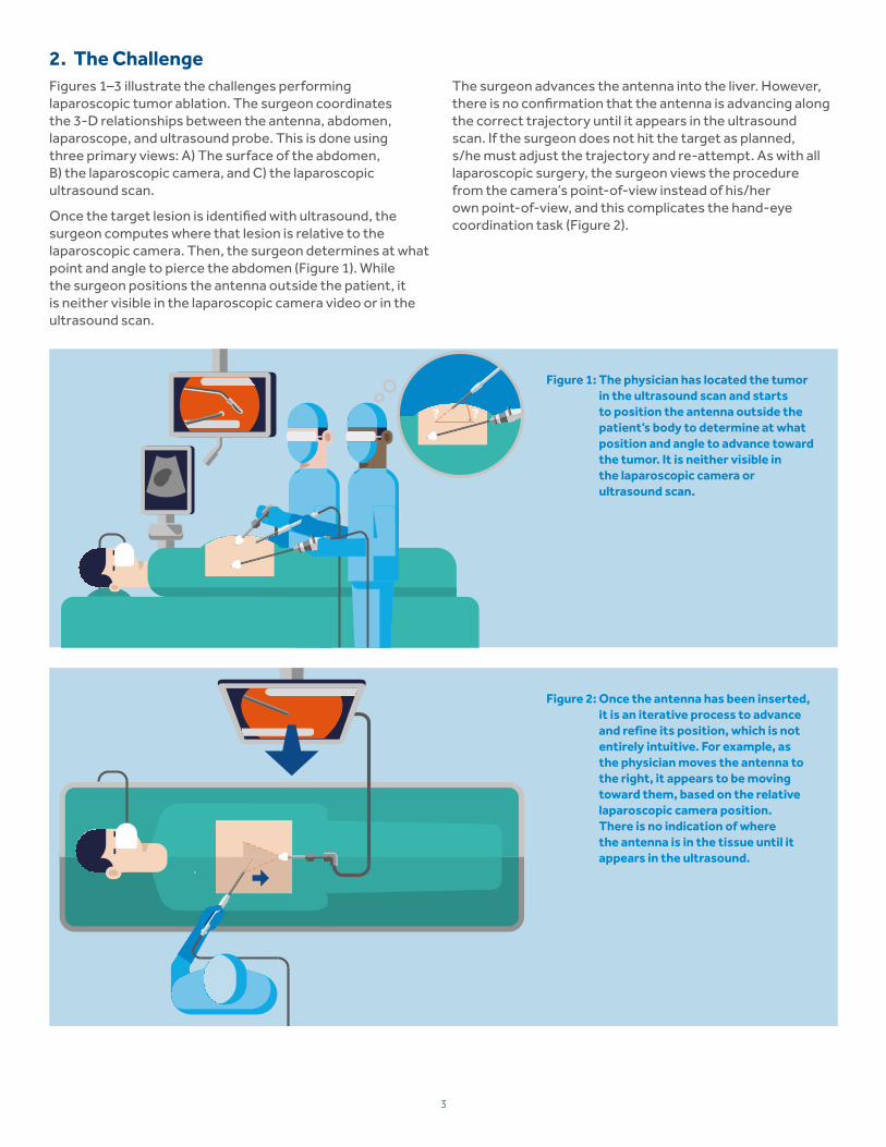
2. The ChallengeFigures 1–3 illustrate the challenges performing laparoscopic tumor ablation. The surgeon coordinates the 3-D relationships between the antenna, abdomen, laparoscope, and ultrasound probe. This is done using three primary views: A) The surface of the abdomen, B) the laparoscopic camera, and C) the laparoscopic ultrasound scan.
Once the target lesion is identified with ultrasound, the surgeon computes where that lesion is relative to the laparoscopic camera. Then, the surgeon determines at what point and angle to pierce the abdomen (Figure 1). While the surgeon positions the antenna outside the patient, it is neither visible in the laparoscopic camera video or in the ultrasound scan.
The surgeon advances the antenna into the liver. However, there is no confirmation that the antenna is advancing along the correct trajectory until it appears in the ultrasound scan. If the surgeon does not hit the target as planned, s/he must adjust the trajectory and re-attempt. As with all laparoscopic surgery, the surgeon views the procedure from the camera’s point-of-view instead of his/her own point-of-view, and this complicates the hand-eye coordination task (Figure 2).
Figure 1: The physician has located the tumor in the ultrasound scan and starts to position the antenna outside the patient’s body to determine at what position and angle to advance toward the tumor. It is neither visible in the laparoscopic camera or ultrasound scan.
Figure 2: Once the antenna has been inserted, it is an iterative process to advance and refine its position, which is not entirely intuitive. For example, as the physician moves the antenna to the right, it appears to be moving toward them, based on the relative laparoscopic camera position. There is no indication of where the antenna is in the tissue until it appears in the ultrasound.
??
4
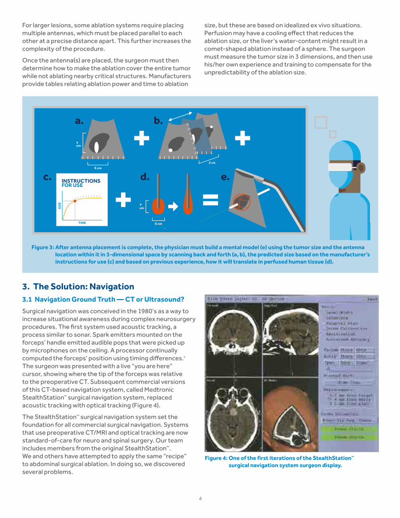
Figure 3: After antenna placement is complete, the physician must build a mental model (e) using the tumor size and the antenna location within it in 3-dimensional space by scanning back and forth (a, b), the predicted size based on the manufacturer’s instructions for use (c) and based on previous experience, how it will translate in perfused human tissue (d).
For larger lesions, some ablation systems require placing multiple antennas, which must be placed parallel to each other at a precise distance apart. This further increases the complexity of the procedure.
Once the antenna(s) are placed, the surgeon must then determine how to make the ablation cover the entire tumor while not ablating nearby critical structures. Manufacturers provide tables relating ablation power and time to ablation
size, but these are based on idealized ex vivo situations. Perfusion may have a cooling effect that reduces the ablation size, or the liver’s water-content might result in a comet-shaped ablation instead of a sphere. The surgeon must measure the tumor size in 3 dimensions, and then use his/her own experience and training to compensate for the unpredictability of the ablation size.
3. The Solution: Navigation3.1 Navigation Ground Truth — CT or Ultrasound?
Surgical navigation was conceived in the 1980’s as a way to increase situational awareness during complex neurosurgery procedures. The first system used acoustic tracking, a process similar to sonar. Spark emitters mounted on the forceps’ handle emitted audible pops that were picked up by microphones on the ceiling. A processor continually computed the forceps’ position using timing differences.7 The surgeon was presented with a live “you are here” cursor, showing where the tip of the forceps was relative to the preoperative CT. Subsequent commercial versions of this CT-based navigation system, called Medtronic StealthStation™ surgical navigation system, replaced acoustic tracking with optical tracking (Figure 4).
The StealthStation™ surgical navigation system set the foundation for all commercial surgical navigation. Systems that use preoperative CT/MRI and optical tracking are now standard-of-care for neuro and spinal surgery. Our team includes members from the original StealthStation™. We and others have attempted to apply the same “recipe” to abdominal surgical ablation. In doing so, we discovered several problems.
Figure 4: One of the first iterations of the StealthStation™ surgical navigation system surgeon display.
X cm
Y cm+ =SI
ZE
TIME
Z cm
+ +X cm
Y cm
a.
c. d. e.
b.
5
3.1.1 Translating for Use in Soft Tissue
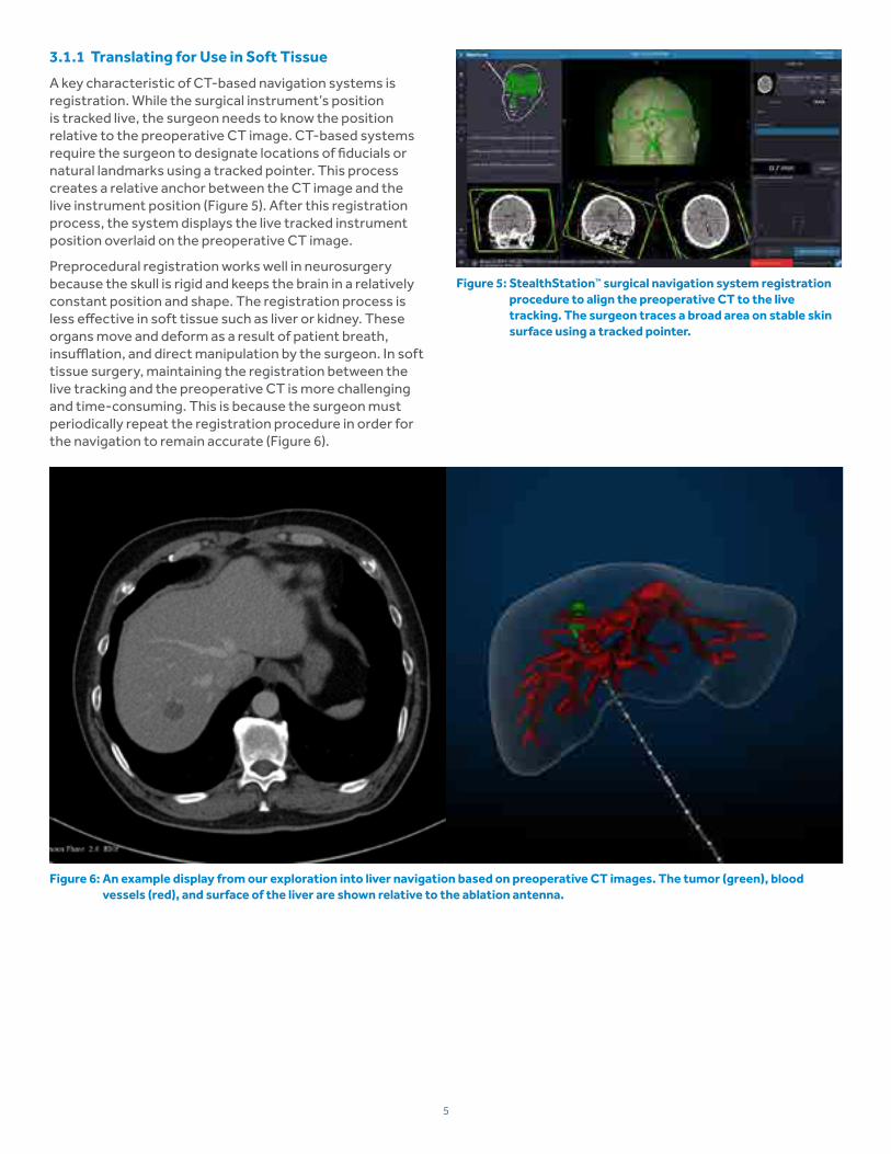
A key characteristic of CT-based navigation systems is registration. While the surgical instrument’s position is tracked live, the surgeon needs to know the position relative to the preoperative CT image. CT-based systems require the surgeon to designate locations of fiducials or natural landmarks using a tracked pointer. This process creates a relative anchor between the CT image and the live instrument position (Figure 5). After this registration process, the system displays the live tracked instrument position overlaid on the preoperative CT image.
Preprocedural registration works well in neurosurgery because the skull is rigid and keeps the brain in a relatively constant position and shape. The registration process is less effective in soft tissue such as liver or kidney. These organs move and deform as a result of patient breath, insufflation, and direct manipulation by the surgeon. In soft tissue surgery, maintaining the registration between the live tracking and the preoperative CT is more challenging and time-consuming. This is because the surgeon must periodically repeat the registration procedure in order for the navigation to remain accurate (Figure 6).
Figure 5: StealthStation™ surgical navigation system registration procedure to align the preoperative CT to the live tracking. The surgeon traces a broad area on stable skin surface using a tracked pointer.
Figure 6: An example display from our exploration into liver navigation based on preoperative CT images. The tumor (green), blood vessels (red), and surface of the liver are shown relative to the ablation antenna.
6
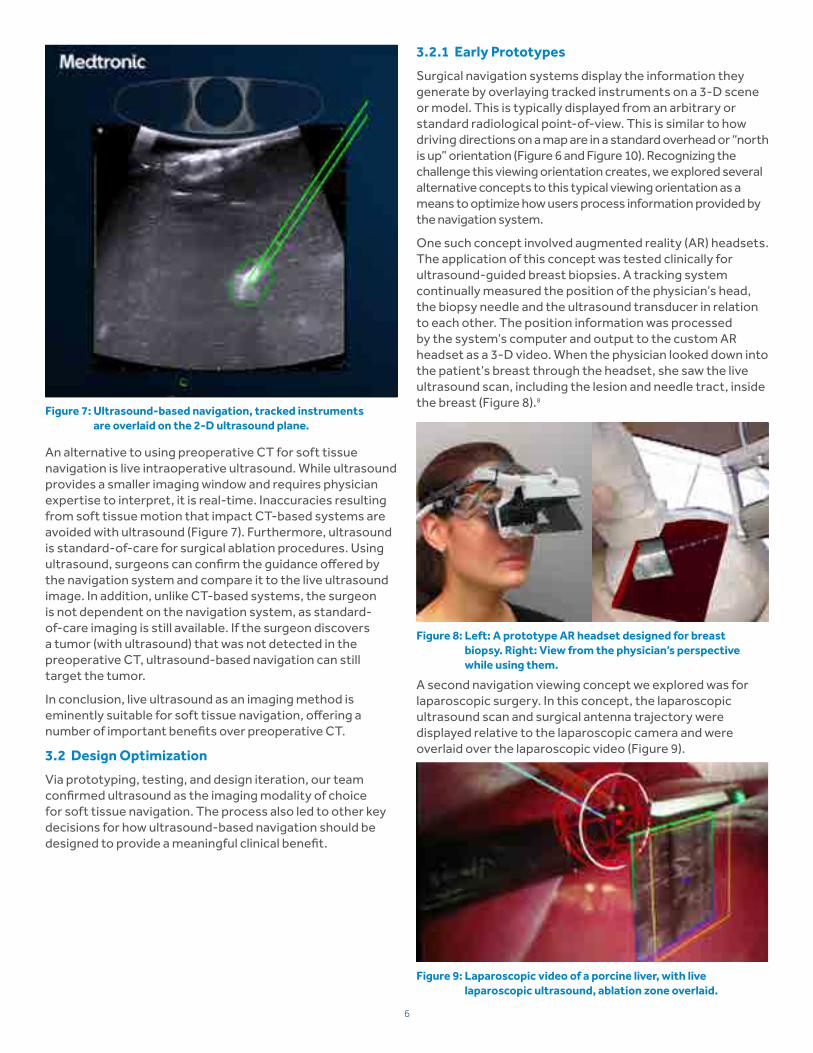
An alternative to using preoperative CT for soft tissue navigation is live intraoperative ultrasound. While ultrasound provides a smaller imaging window and requires physician expertise to interpret, it is real-time. Inaccuracies resulting from soft tissue motion that impact CT-based systems are avoided with ultrasound (Figure 7). Furthermore, ultrasound is standard-of-care for surgical ablation procedures. Using ultrasound, surgeons can confirm the guidance offered by the navigation system and compare it to the live ultrasound image. In addition, unlike CT-based systems, the surgeon is not dependent on the navigation system, as standard-of-care imaging is still available. If the surgeon discovers a tumor (with ultrasound) that was not detected in the preoperative CT, ultrasound-based navigation can still target the tumor.
In conclusion, live ultrasound as an imaging method is eminently suitable for soft tissue navigation, offering a number of important benefits over preoperative CT.
3.2 Design Optimization
Via prototyping, testing, and design iteration, our team confirmed ultrasound as the imaging modality of choice for soft tissue navigation. The process also led to other key decisions for how ultrasound-based navigation should be designed to provide a meaningful clinical benefit.
3.2.1 Early Prototypes
Surgical navigation systems display the information they generate by overlaying tracked instruments on a 3-D scene or model. This is typically displayed from an arbitrary or standard radiological point-of-view. This is similar to how driving directions on a map are in a standard overhead or “north is up” orientation (Figure 6 and Figure 10). Recognizing the challenge this viewing orientation creates, we explored several alternative concepts to this typical viewing orientation as a means to optimize how users process information provided by the navigation system.
One such concept involved augmented reality (AR) headsets. The application of this concept was tested clinically for ultrasound-guided breast biopsies. A tracking system continually measured the position of the physician’s head, the biopsy needle and the ultrasound transducer in relation to each other. The position information was processed by the system’s computer and output to the custom AR headset as a 3-D video. When the physician looked down into the patient’s breast through the headset, she saw the live ultrasound scan, including the lesion and needle tract, inside the breast (Figure 8).8
Figure 7: Ultrasound-based navigation, tracked instruments are overlaid on the 2-D ultrasound plane.
Figure 8: Left: A prototype AR headset designed for breast biopsy. Right: View from the physician’s perspective while using them.
Figure 9: Laparoscopic video of a porcine liver, with live laparoscopic ultrasound, ablation zone overlaid.
A second navigation viewing concept we explored was for laparoscopic surgery. In this concept, the laparoscopic ultrasound scan and surgical antenna trajectory were displayed relative to the laparoscopic camera and were overlaid over the laparoscopic video (Figure 9).
7
3.2.2 Key Attributes
Preclinical and clinical experiences from these early prototypes identified key features that would make an ultrasound-based navigation system intuitive, effective, and easy to use.
For example, we learned that the system must react very quickly to user motion. Some of the early concept prototypes exhibited lag between user motion and navigation system output. This lag created some discomfort and uncertainty for users. By redesigning the system to minimize latency, the system output became fluid.9
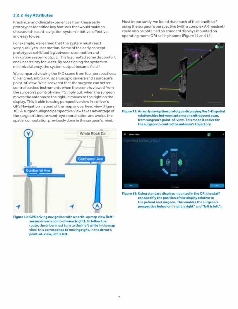
We compared viewing the 3-D scene from four perspectives: CT-aligned, arbitrary, laparoscopic camera and a surgeon’s point-of-view. We discovered that the surgeon can better control tracked instruments when the scene is viewed from the surgeon’s point-of-view.10 Simply put, when the surgeon moves the antenna to the right, it moves to the right on the display. This is akin to using perspective view in a driver’s GPS Navigation instead of the map or overhead view (Figure 10). A surgeon-aligned perspective view takes advantage of the surgeon’s innate hand-eye coordination and avoids the spatial computation previously done in the surgeon’s mind.
Most importantly, we found that much of the benefits of using the surgeon’s perspective (with a complex AR headset) could also be obtained on standard displays mounted on operating room (OR) ceiling booms (Figure 11 and 12).
Figure 10: GPS driving navigation with a north-up map view (left) versus driver’s point-of-view (right). To follow the route, the driver must turn to their left while in the map view, this corresponds to moving right. In the driver’s point-of-view, left is left.
Figure 12: Using standard displays mounted in the OR, the staff can specifiy the position of the display relative to the patient and surgeon. This enables the surgeon’s perspective behavior (“right is right” and “left is left”).
Figure 11: An early navigation prototype displaying the 3-D spatial relationships between antenna and ultrasound scan, from surgeon’s point-of-view. This made it easier for the surgeon to control the antenna’s trajectory.
8
3.3 Optical Versus Electromagnetic (EM) Tracking
All navigation systems include tracking: continuously measuring the positions of instruments as the surgeon moves them. During our development process, we evaluated two types of tracking – optical and electromagnetic.
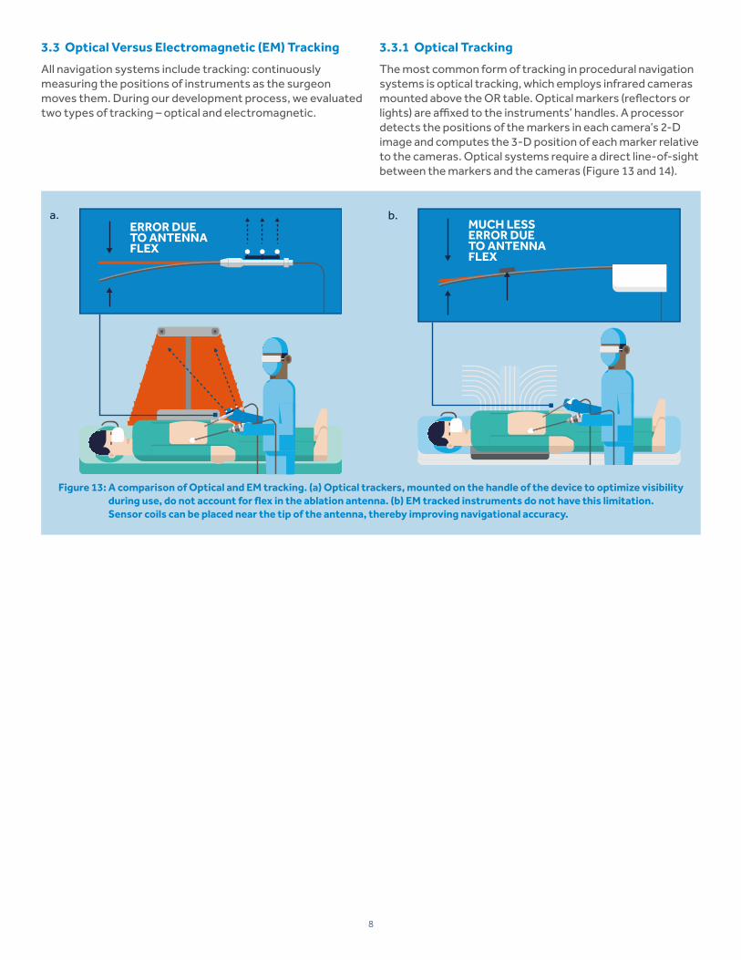
Figure 13: A comparison of Optical and EM tracking. (a) Optical trackers, mounted on the handle of the device to optimize visibility during use, do not account for flex in the ablation antenna. (b) EM tracked instruments do not have this limitation. Sensor coils can be placed near the tip of the antenna, thereby improving navigational accuracy.
3.3.1 Optical Tracking
The most common form of tracking in procedural navigation systems is optical tracking, which employs infrared cameras mounted above the OR table. Optical markers (reflectors or lights) are affixed to the instruments’ handles. A processor detects the positions of the markers in each camera’s 2-D image and computes the 3-D position of each marker relative to the cameras. Optical systems require a direct line-of-sight between the markers and the cameras (Figure 13 and 14).
a. b.MUCH LESSERROR DUE TO ANTENNA FLEX
ERROR DUE TO ANTENNA FLEX
9
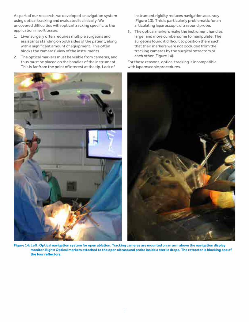
Figure 14: Left: Optical navigation system for open ablation. Tracking cameras are mounted on an arm above the navigation display monitor. Right: Optical markers attached to the open ultrasound probe inside a sterile drape. The retractor is blocking one of the four reflectors.
As part of our research, we developed a navigation system using optical tracking and evaluated it clinically. We uncovered difficulties with optical tracking specific to the application in soft tissue:
1. Liver surgery often requires multiple surgeons and assistants standing on both sides of the patient, along with a significant amount of equipment. This often blocks the cameras’ view of the instruments.
2. The optical markers must be visible from cameras, and thus must be placed on the handles of the instrument. This is far from the point of interest at the tip. Lack of
instrument rigidity reduces navigation accuracy (Figure 13). This is particularly problematic for an articulating laparoscopic ultrasound probe.
3. The optical markers make the instrument handles larger and more cumbersome to manipulate. The surgeons found it difficult to position them such that their markers were not occluded from the tracking cameras by the surgical retractors or each other (Figure 14).
For these reasons, optical tracking is incompatible with laparoscopic procedures.
10
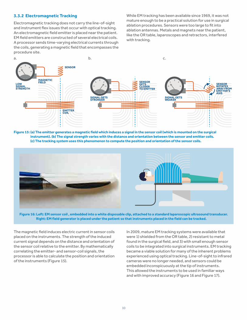
Figure 16: Left: EM sensor coil , embedded into a white disposable clip, attached to a standard laparoscopic ultrasound transducer. Right: EM field generator is placed under the patient so that instruments placed in the field can be tracked.
The magnetic field induces electric current in sensor coils placed on the instruments. The strength of the induced current signal depends on the distance and orientation of the sensor coil relative to the emitter. By mathematically correlating the emitter- and sensor-coil signals, the processor is able to calculate the position and orientation of the instruments (Figure 15).
In 2009, mature EM tracking systems were available that were 1) shielded from the OR table, 2) resistant to metal found in the surgical field, and 3) with small enough sensor coils to be integrated into surgical instruments. EM tracking became a viable solution for many of the inherent problems experienced using optical tracking. Line-of-sight to infrared cameras were no longer needed, and sensors could be embedded inconspicuously at the tip of instruments. This allowed the instruments to be used in familiar ways and with improved accuracy (Figure 16 and Figure 17).
Figure 15: (a) The emitter generates a magnetic field which induces a signal in the sensor coil (which is mounted on the surgical instrument). (b) The signal strength varies with the distance and orientation between the sensor and emitter coils. (c) The tracking system uses this phenomenon to compute the position and orientation of the sensor coils.
3.3.2 Electromagnetic Tracking
Electromagnetic tracking does not carry the line-of-sight and instrument flex issues that occur with optical tracking. An electromagnetic field emitter is placed near the patient. EM field emitters are constructed of several electrical coils. A processor sends time-varying electrical currents through the coils, generating a magnetic field that encompasses the procedure site.
While EM tracking has been available since 1969, it was not mature enough to be a practical solution for use in surgical ablation procedures. Sensors were too large to fit into ablation antennas. Metals and magnets near the patient, like the OR table, laparoscopes and retractors, interfered with tracking.
a. b. c.
LOWSIGNALSTRENGTH
SENSOR
EMITTERCOIL
MAGNETICFIELD
SIGNAL GETSSTRONGER
SENSORGETS CLOSER TO EMITTER
SIGNAL GETS WEAKER
SENSORROTATESAWAY FROMEMITTER’S AXIS
11
3.4 Simple and Integrated
In conjunction with these discrete design choices, we employed contextual observation to refine the optimal procedural flow and create a truly “plug and play” system.
Bringing new technology into any procedural environment comes with trade-offs, including additional staff training and set-up time. With a focus on creating soft tissue navigation that is simple and integrated, we designed the ablation generator and navigation into a single system. This eliminated the need to set up, configure, and calibrate two separate systems.
One breakthrough was the realization that the surgeon and OR staff work together to operate the system but have different needs. For example, a surgeon’s focus is controlling
the antenna, whereas the OR staff are responsible for connecting and configuring all the equipment. Because of this, the user interface was separated into two. One is on a boom-mounted OR display for the surgeon, and the other is on a touchscreen as part of the Emprint™ SX ablation platform (Figure 18). The OR staff’s burden was further reduced by step-by-step instructions for connecting each piece of equipment and providing context-sensitive troubleshooting. This innovative design strategy was validated by over 15 novice teams (one surgeon and one nurse each), working together on simulated ablation procedures. Teams completed tasks related to the system including OR setup, targeting, ablating, and troubleshooting.11
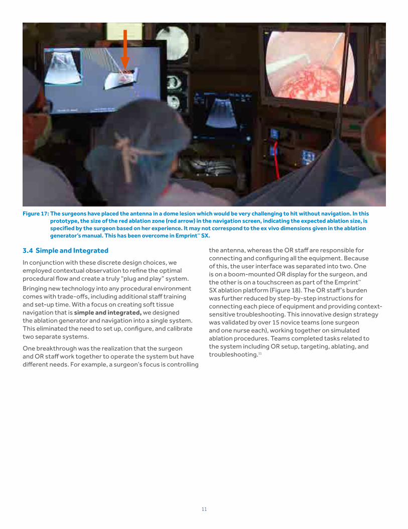
Figure 17: The surgeons have placed the antenna in a dome lesion which would be very challenging to hit without navigation. In this prototype, the size of the red ablation zone (red arrow) in the navigation screen, indicating the expected ablation size, is specified by the surgeon based on her experience. It may not correspond to the ex vivo dimensions given in the ablation generator’s manual. This has been overcome in Emprint™ SX.
12
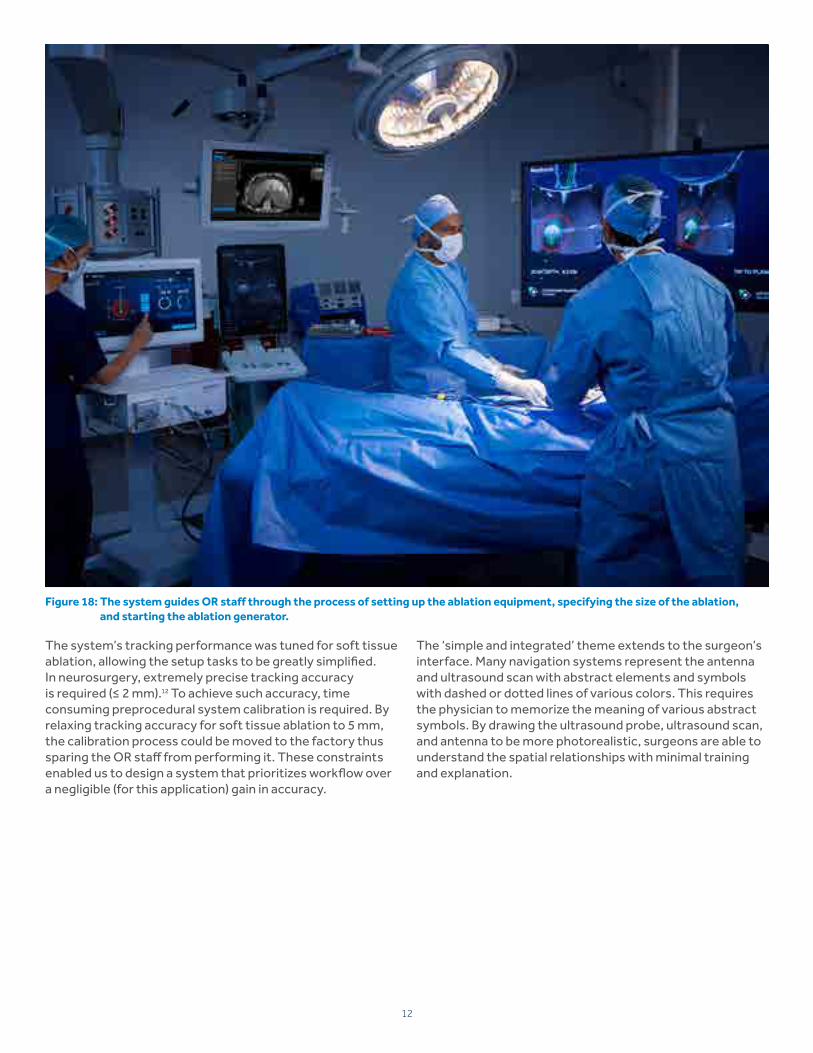
Figure 18: The system guides OR staff through the process of setting up the ablation equipment, specifying the size of the ablation, and starting the ablation generator.
The system’s tracking performance was tuned for soft tissue ablation, allowing the setup tasks to be greatly simplified. In neurosurgery, extremely precise tracking accuracy is required (≤ 2 mm).12 To achieve such accuracy, time consuming preprocedural system calibration is required. By relaxing tracking accuracy for soft tissue ablation to 5 mm, the calibration process could be moved to the factory thus sparing the OR staff from performing it. These constraints enabled us to design a system that prioritizes workflow over a negligible (for this application) gain in accuracy.
The ‘simple and integrated’ theme extends to the surgeon’s interface. Many navigation systems represent the antenna and ultrasound scan with abstract elements and symbols with dashed or dotted lines of various colors. This requires the physician to memorize the meaning of various abstract symbols. By drawing the ultrasound probe, ultrasound scan, and antenna to be more photorealistic, surgeons are able to understand the spatial relationships with minimal training and explanation.
13
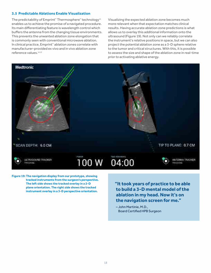
“It took years of practice to be able to build a 3-D mental model of the ablation in my head. Now it’s on the navigation screen for me.” – John Martinie, M.D.,
Board Certified HPB Surgeon
3.5 Predictable Ablations Enable Visualization
The predictability of Emprint™ Thermosphere™ technology13 enables us to achieve the promise of a navigated procedure. Its main differentiating feature is wavelength control which buffers the antenna from the changing tissue environments. This prevents the unwanted ablation zone elongation that is commonly seen with conventional microwave ablation. In clinical practice, Emprint™ ablation zones correlate with manufacturer-provided ex vivo and in vivo ablation zone reference values.14,15
Visualizing the expected ablation zone becomes much more relevant when that expectation matches clinical results. Having accurate ablation zone predictions is what allows us to overlay this additional information onto the ultrasound (Figure 19). Not only can we reliably correlate the instrument’s relative positions in space, but we can also project the potential ablation zone as a 3-D sphere relative to the tumor and critical structures. With this, it is possible to assess the size and shape of the ablation zone in real-time prior to activating ablative energy.
Figure 19: The navigation display from our prototype, showing tracked instruments from the surgeon’s perspective. The left side shows the tracked overlay in a 2-D plane orientation. The right side shows the tracked instrument overlay in a 3-D perspective orientation.
14
4. The Intended ImpactAcross multiple specialties and disciplines, navigation has become a natural extension of the surgical armamentarium. Medtronic StealthStation™ surgical navigation system helped 3-D navigation make its first inroads in neurosurgery where there was a clear need to reduce procedural complexity and safety risks. Clinical studies confirmed the value of navigation, demonstrating improved patient outcomes, lower cost, and an ability to perform more difficult and less invasive procedures.16,17
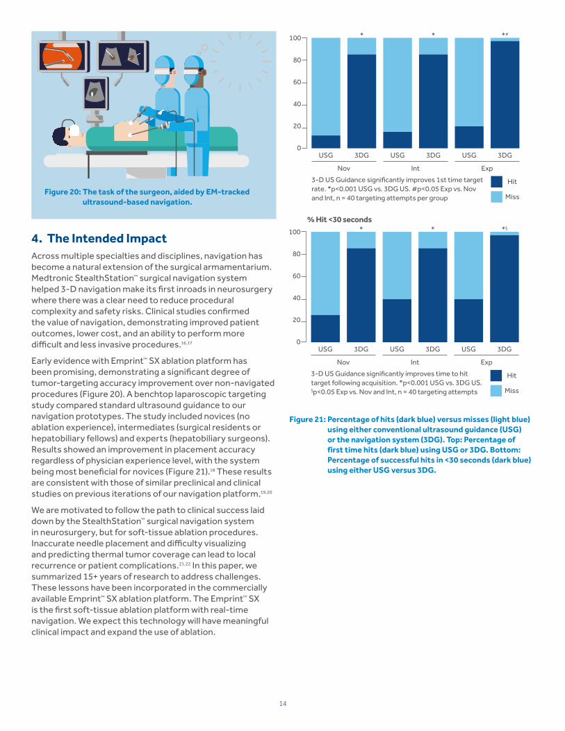
Early evidence with Emprint™ SX ablation platform has been promising, demonstrating a significant degree of tumor-targeting accuracy improvement over non-navigated procedures (Figure 20). A benchtop laparoscopic targeting study compared standard ultrasound guidance to our navigation prototypes. The study included novices (no ablation experience), intermediates (surgical residents or hepatobiliary fellows) and experts (hepatobiliary surgeons). Results showed an improvement in placement accuracy regardless of physician experience level, with the system being most beneficial for novices (Figure 21).18 These results are consistent with those of similar preclinical and clinical studies on previous iterations of our navigation platform.19,20
We are motivated to follow the path to clinical success laid down by the StealthStation™ surgical navigation system in neurosurgery, but for soft-tissue ablation procedures. Inaccurate needle placement and difficulty visualizing and predicting thermal tumor coverage can lead to local recurrence or patient complications.21,22 In this paper, we summarized 15+ years of research to address challenges. These lessons have been incorporated in the commercially available Emprint™ SX ablation platform. The Emprint™ SX is the first soft-tissue ablation platform with real-time navigation. We expect this technology will have meaningful clinical impact and expand the use of ablation.
Figure 20: The task of the surgeon, aided by EM-tracked ultrasound-based navigation.
Figure 21: Percentage of hits (dark blue) versus misses (light blue) using either conventional ultrasound guidance (USG) or the navigation system (3DG). Top: Percentage of first time hits (dark blue) using USG or 3DG. Bottom: Percentage of successful hits in <30 seconds (dark blue) using either USG versus 3DG.
% First time hit* * *#
USG 3DG
Nov Int Exp
USG 3DG USG 3DG
Hit
Miss
3-D US Guidance significantly improves 1st time target rate. *p<0.001 USG vs. 3DG US. #p<0.05 Exp vs. Nov and Int, n = 40 targeting attempts per group
100
80
60
40
20
0
% Hit <30 seconds* * *§
100
80
60
40
20
0USG 3DG
Nov Int Exp
USG 3DG USG 3DG
3-D US Guidance significantly improves time to hit target following acquisition. *p<0.001 USG vs. 3DG US. §p<0.05 Exp vs. Nov and Int, n = 40 targeting attempts per group
Hit
Miss
15
References
1. Bruix J, Reig M, Sherman M. Evidence-based diagnosis, staging, and treatment of patients with hepatocellular carcinoma. Gastroenterology 2016;150:835–853.2. Ruers T, Van Coevorden F, Punt CJ, et al. Local treatment of unresectable colorectal liver metastases: Results of a randomized phase II trial. J Natl Cancer Inst
2017;109(9): djx015.3. Krokidis ME, Orsi F, Katsanos K, Helmberger T, Adam A. CIRSE guidelines on percutaneous ablation of small renal cell carcinoma. Cardiovasc Intervent Radiol.
Published Dec. 16, 2016.4. Medtronic. Advanced Ablation Solutions Market Analysis. 2015.5. Poon RT, Ng KK, Lam CM, et al. Learning curve for radiofrequency ablation of liver tumors: prospective analysis of initial 100 patients in a tertiary institution.
Ann Surg. 2004;239(4):441–9.6. Hildebrand P, Leibecke T, Kleemann M, et al. Influence of operator experience in radiofrequency ablation of malignant liver tumours on treatment outcome.
Eur J Surg Oncol. 2006;32(4):430–4.7. Editors: Lozano, Andres M, Gildenberg, Phillip L, Tasker, Ronald R. Textbook of Stereotactic and Functional Neurosurgery, Vol 1. Springer Science & Business Media,
Jun 22, 2009:548.8. State A, Livingston MA, Garrett WF, et al. Technologies for augmented-reality systems: Realizing ultrasound-guided needle biopsies. Proc. SIGGRAPH 96 (New
Orleans, LA, August 4-9, 1996). In Computer Graphics Proceedings, Annual Conference Series, 1996, ACM SIGGRAPH, 439–446. 9. Meehan M, Razzaque S, Whitton MC, Brooks FP. Effect of latency on presence in stressful virtual environments. IEEE Virtual Reality Proceedings. 2003.10. Fuchs H (PhD), State A, Yang H, et al. Optimizing a head-tracked stereo display system to guide hepatic tumor ablation. Proc. Medicine Meets Virtual
Reality(MMVR) 2008 (Newport Beach, CA, January 29-February 1, 2008). In Stud Health Technol Inform. 2008;132:126–31. 11. Sohlden R, Girotto D, Goss R, et al. Team personas in product development. Human Factors and Ergonomics in Health Care. March 5–8 2017.12. U.S. Food and Drug Administration, Center for Devices and Radiological Heatlh. StealthStation™ surgical navigation system S8 510(k) K162309 clearance letter,
August 16, 2016. Retrieved August 4, 2017, 13. Joe Brannan. Thermal ablation: Understanding the breakthrough to predictability spherical ablations with ThermosphereTM technology. Medtronic.
Ref#1090259. 2015.14. De Cobelli F, Marra P, Ratti F, et al. Microwave ablation of liver malignancies: comparison of effects and early outcomes of percutaneous and intraoperative
approaches with different liver conditions. Med Oncol. 2017: 34(49).15. Zaidi N, Okoh A, Yigitbas H, Yazici P, Ali N, Berber E. Laproscopic microwave ThermosphereTM ablation of malignant liver tumors: An analysis of 53 cases.
J Surg Onc. 2016(113):130-134.16. Mezger U, Jendrewski C, Bartels M. Navigation in surgery. Langenbecks Arch Surg. 2013(398):501–514.17. Roessler K, Sommer B, Grummich P, et al. Improved resection in lesional temporal lobe epilepsy surgery using neuronavigation and intraoperative MR imaging:
Favourable long term surgical and seizure outcome in 88 consecutive cases. Seizure. 2014(23):201–207.18. Iannitti D, Sastry A, Swet J, et al. A novel 3-dimensional electromagnetic guidance system increases microwave antenna placement accuracy. AHPBA. 2017.19. Based on internal study #RE00085432. An acute GLP study to evaluate the performance and safety of the Emprint™ SX — Ablation platform in a porcine
model. 2017.20. Sindram D, Simo KA, Swan RZ, et al. Laparoscopic microwave ablation of human liver tumours using a novel three-dimensional magnetic guidance system.
HPB 2015; 17: 87–93.21. Muiller et al. Local recurrence after hepatic radiofrequency coagulation. Annals of Surgery. 2005: 242:2. 22. Poon RT, Ng KK, Lam CM, et al. Learning curve for radiofrequency ablation of liver tumors: Prospective analysis of initial 100 patients in a tertiary institution.
Ann Surg. 2004;239(4):441-9.
Indications for Use: The Emprint™ SX ablation platform with Thermosphere™ technology is intended for use in percutaneous, laparoscopic, and intraoperative coagulation (ablation) of soft tissue, including partial or complete ablation of non-resectable liver tumors. The system’s optional 3-D guidance feature assists in the placement of the Emprint™ SX navigation antenna with Thermosphere™ technology using real-time image guidance during intraoperative and laparoscopic ablation procedures. The navigation feature enhances the output of a compatible medical ultrasound imagining system and displays an image of the antenna and its predicted trajectory on a computer monitor. The size and shape of the predicted zone relative to the position of the antenna is displayed on the enhanced ultrasound image.
Risk Statement: See product labeling for the complete list of indications, warnings, precautions, and other important medical information.