Page 1
Navigation instrument - ILS Version 2.1 31 May 2017 Page 1
© IVAO HQ training department Training Documentation Manager Erwan L’hotellier
This manual is dedicated only for IVAOTM Network activities. This document must not be used in real aviation or in other networks
NAVIGATION INSTRUMENTATION – ILS
1. Introduction
The instrument landing system (ILS) is the ICAO standard, non-visual aid to final approach and landing.
The ILS is defined as a precision runway approach aid which provides pilots with both vertical and
horizontal guidance during an approach to land.
Ground equipment consists of 2 directional transmitting systems and sometimes paired with 2 or 3 marker
beacons along the approach. The directional transmitters are known as the localizer and the glide slope.
The instrument landing system (ILS) provides the pilot with:
Guidance information regarding the approach path derived from the localizer and the glide slope
Range information at significant points along the approach path by marker beacons or continuous
range information from distance measuring equipment (DME)
Visual information in the last phase of flight from approach lights, touchdown and centre line lights,
runway lights
The identification of an ILS is transmitted in International Morse Code and consists of a 2 or 3 letter
identifier.
Page 2
Navigation instrument - ILS Version 2.1 31 May 2017 Page 2
© IVAO HQ training department Training Documentation Manager Erwan L’hotellier
This manual is dedicated only for IVAOTM Network activities. This document must not be used in real aviation or in other networks
2. Ground equipment: ILS
2.1. Localizer
The localizer transmitter operates on one of 40 ILS channels within the very-high frequency (VHF) band
from 108 MHz to 112 MHz
Each localizer’s frequency first decimal shall be odd like the following examples: 108.1, 108.15, 108.3, and
108.35.
The localizer system consists of a network system from 13 to 41 VHF antennas.
Localizer network using log periodic antennas
Localizer network using quad antennas
Page 3
Navigation instrument - ILS Version 2.1 31 May 2017 Page 3
© IVAO HQ training department Training Documentation Manager Erwan L’hotellier
This manual is dedicated only for IVAOTM Network activities. This document must not be used in real aviation or in other networks
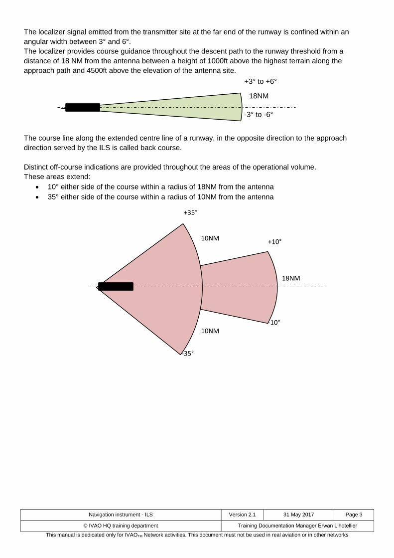
The localizer signal emitted from the transmitter site at the far end of the runway is confined within an
angular width between 3° and 6°.
The localizer provides course guidance throughout the descent path to the runway threshold from a
distance of 18 NM from the antenna between a height of 1000ft above the highest terrain along the
approach path and 4500ft above the elevation of the antenna site.
The course line along the extended centre line of a runway, in the opposite direction to the approach
direction served by the ILS is called back course.
Distinct off-course indications are provided throughout the areas of the operational volume.
These areas extend:
10° either side of the course within a radius of 18NM from the antenna
35° either side of the course within a radius of 10NM from the antenna
10NM
18NM
+10°
-10°
-35°
+35°
10NM
18NM
+3° to +6°
-3° to -6°
Page 4
Navigation instrument - ILS Version 2.1 31 May 2017 Page 4
© IVAO HQ training department Training Documentation Manager Erwan L’hotellier
This manual is dedicated only for IVAOTM Network activities. This document must not be used in real aviation or in other networks
2.2. Glide Path
The glide slope transmitter operates on one of 40 ILS channels within the ultra-high frequency (UHF) band
from 329.15 MHz to 335MHz. The glide path radiates its signal only in the direction of the localizer front
course.
The glide slope frequency is usually paired with the localizer frequency as the pilot enters only the localizer
frequency in the aircraft instruments.
The glide scope transmitter is located between 230m/750ft and 380m/1250ft from the approach end of the
runway and offset between 75m/250ft and 198m/650ft from the runway centre line.
It transmits a glide path with a beam width of 1.4°. The glide path projection angle is normally adjusted to 3°
above the horizontal plane so that it passes through the middle marker at about 60m/200ft and the outer
marker at about 426m/1400ft.
The glide slope is normally usable to a distance of 10NM (it can be extended when requested). The glide
path provided by the glide slope transmitter is arranged so that it flares from 5 to 8m (18 to 27ft) above the
runway.
It should not be expected that the glide path will provide guidance to the touchdown point on the runway.
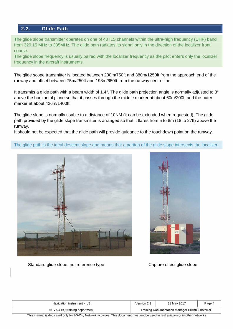
The glide path is the ideal descent slope and means that a portion of the glide slope intersects the localizer.
Standard glide slope: nul reference type Capture effect glide slope
Page 5
Navigation instrument - ILS Version 2.1 31 May 2017 Page 5
© IVAO HQ training department Training Documentation Manager Erwan L’hotellier
This manual is dedicated only for IVAOTM Network activities. This document must not be used in real aviation or in other networks
There are 5 glide slope systems:
Null-reference,
Sideband-reference
Capture-effect
Endfire
Waveguide
The null-reference, sideband-reference and capture-effect glide slope are image effect systems. They use
ground reflexion in order to generate a radio electromagnetic field. The stability of this field is dependent on
the weather condition (wet ground, snowy ground).
The sideband-reference system is normally used when the runway is descending towards the end
threshold.
The capture-reference system is normally used when the runway is climbing towards the end threshold.
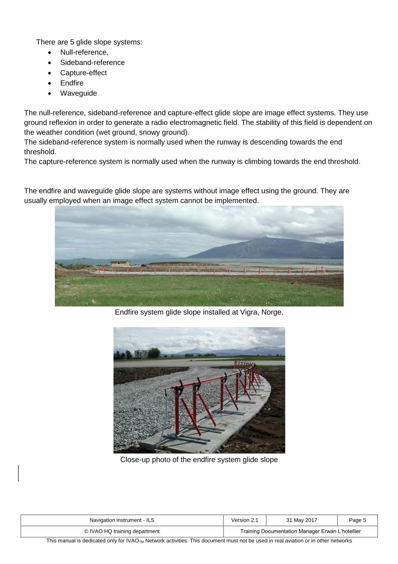
The endfire and waveguide glide slope are systems without image effect using the ground. They are
usually employed when an image effect system cannot be implemented.
Endfire system glide slope installed at Vigra, Norge.
Close-up photo of the endfire system glide slope
Page 6
Navigation instrument - ILS Version 2.1 31 May 2017 Page 6
© IVAO HQ training department Training Documentation Manager Erwan L’hotellier
This manual is dedicated only for IVAOTM Network activities. This document must not be used in real aviation or in other networks
2.3. ILS performance limitations
Glide slope and localizer signals are adversely affected by reflecting objects such as hangars, etc.
At some locations, snow and tidal reflections also affect the glide path angle to a noticeable degree.
In addition, the limited number of channels available for use by ILS may cause interference problems in
areas where, due to the proximity of aerodromes, a large number of ILS are required.
Page 7
Navigation instrument - ILS Version 2.1 31 May 2017 Page 7
© IVAO HQ training department Training Documentation Manager Erwan L’hotellier
This manual is dedicated only for IVAOTM Network activities. This document must not be used in real aviation or in other networks
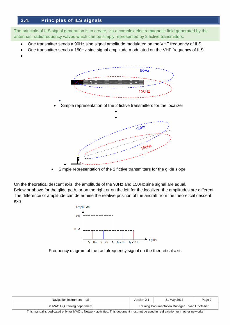
2.4. Principles of ILS signals
The principle of ILS signal generation is to create, via a complex electromagnetic field generated by the
antennas, radiofrequency waves which can be simply represented by 2 fictive transmitters:
One transmitter sends a 90Hz sine signal amplitude modulated on the VHF frequency of ILS.
One transmitter sends a 150Hz sine signal amplitude modulated on the VHF frequency of ILS.
Simple representation of the 2 fictive transmitters for the localizer
Simple representation of the 2 fictive transmitters for the glide slope
On the theoretical descent axis, the amplitude of the 90Hz and 150Hz sine signal are equal.
Below or above for the glide path, or on the right or on the left for the localizer, the amplitudes are different.
The difference of amplitude can determine the relative position of the aircraft from the theoretical descent
axis.
Frequency diagram of the radiofrequency signal on the theoretical axis
Page 8
Navigation instrument - ILS Version 2.1 31 May 2017 Page 8
© IVAO HQ training department Training Documentation Manager Erwan L’hotellier
This manual is dedicated only for IVAOTM Network activities. This document must not be used in real aviation or in other networks
2.5. Operational application and ILS categories
An approach may not normally be continued unless the runway visual range (RVR) is above the specified
minimum.
The pilot should follow the ILS guidance until the decision height (DH) is reached. DH shall be published on
instrument approach charts (IAC) of the concerned airfield. At the DH, the approach may only be continued
if the specified visual reference is available; otherwise, a go-around must be flown.
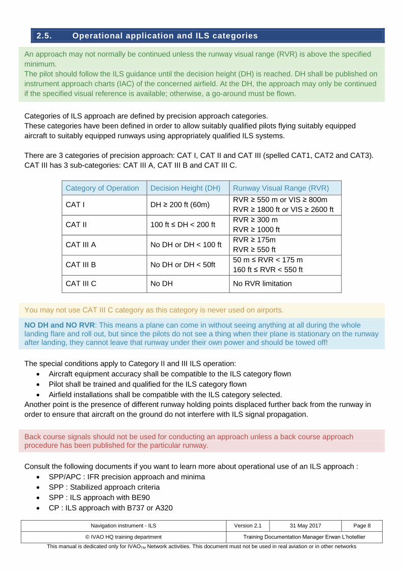
Categories of ILS approach are defined by precision approach categories.
These categories have been defined in order to allow suitably qualified pilots flying suitably equipped
aircraft to suitably equipped runways using appropriately qualified ILS systems.
There are 3 categories of precision approach: CAT I, CAT II and CAT III (spelled CAT1, CAT2 and CAT3).
CAT III has 3 sub-categories: CAT III A, CAT III B and CAT III C.
Category of Operation Decision Height (DH) Runway Visual Range (RVR)
CAT I DH ≥ 200 ft (60m) RVR ≥ 550 m or VIS ≥ 800m
RVR ≥ 1800 ft or VIS ≥ 2600 ft
CAT II 100 ft ≤ DH < 200 ft RVR ≥ 300 m
RVR ≥ 1000 ft
CAT III A No DH or DH < 100 ft RVR ≥ 175m
RVR ≥ 550 ft
CAT III B No DH or DH < 50ft 50 m ≤ RVR < 175 m
160 ft ≤ RVR < 550 ft
CAT III C No DH No RVR limitation
You may not use CAT III C category as this category is never used on airports.
NO DH and NO RVR: This means a plane can come in without seeing anything at all during the whole landing flare and roll out, but since the pilots do not see a thing when their plane is stationary on the runway after landing, they cannot leave that runway under their own power and should be towed off!
The special conditions apply to Category II and III ILS operation:
Aircraft equipment accuracy shall be compatible to the ILS category flown
Pilot shall be trained and qualified for the ILS category flown
Airfield installations shall be compatible with the ILS category selected.
Another point is the presence of different runway holding points displaced further back from the runway in
order to ensure that aircraft on the ground do not interfere with ILS signal propagation.
Back course signals should not be used for conducting an approach unless a back course approach procedure has been published for the particular runway.
Consult the following documents if you want to learn more about operational use of an ILS approach :
SPP/APC : IFR precision approach and minima
SPP : Stabilized approach criteria
SPP : ILS approach with BE90
CP : ILS approach with B737 or A320
Page 9
Navigation instrument - ILS Version 2.1 31 May 2017 Page 9
© IVAO HQ training department Training Documentation Manager Erwan L’hotellier
This manual is dedicated only for IVAOTM Network activities. This document must not be used in real aviation or in other networks
3. ILS on charts
The symbol of the ILS on charts can be one of these symbols.
But many charts have no specific symbol for ILS (ILS is written in the procedure name).
front track ILS back course ILS Offset ILS
On the chart above, you can see front track ILS sign.
On the chart above, the ILS is represented with just a simple straight line.
4. On-board equipment: ILS
Page 10
Navigation instrument - ILS Version 2.1 31 May 2017 Page 10
© IVAO HQ training department Training Documentation Manager Erwan L’hotellier
This manual is dedicated only for IVAOTM Network activities. This document must not be used in real aviation or in other networks
The on-board equipment controls demodulating the VHF ILS signal in order to get the amplitude of the
90Hz and 150z modulation.
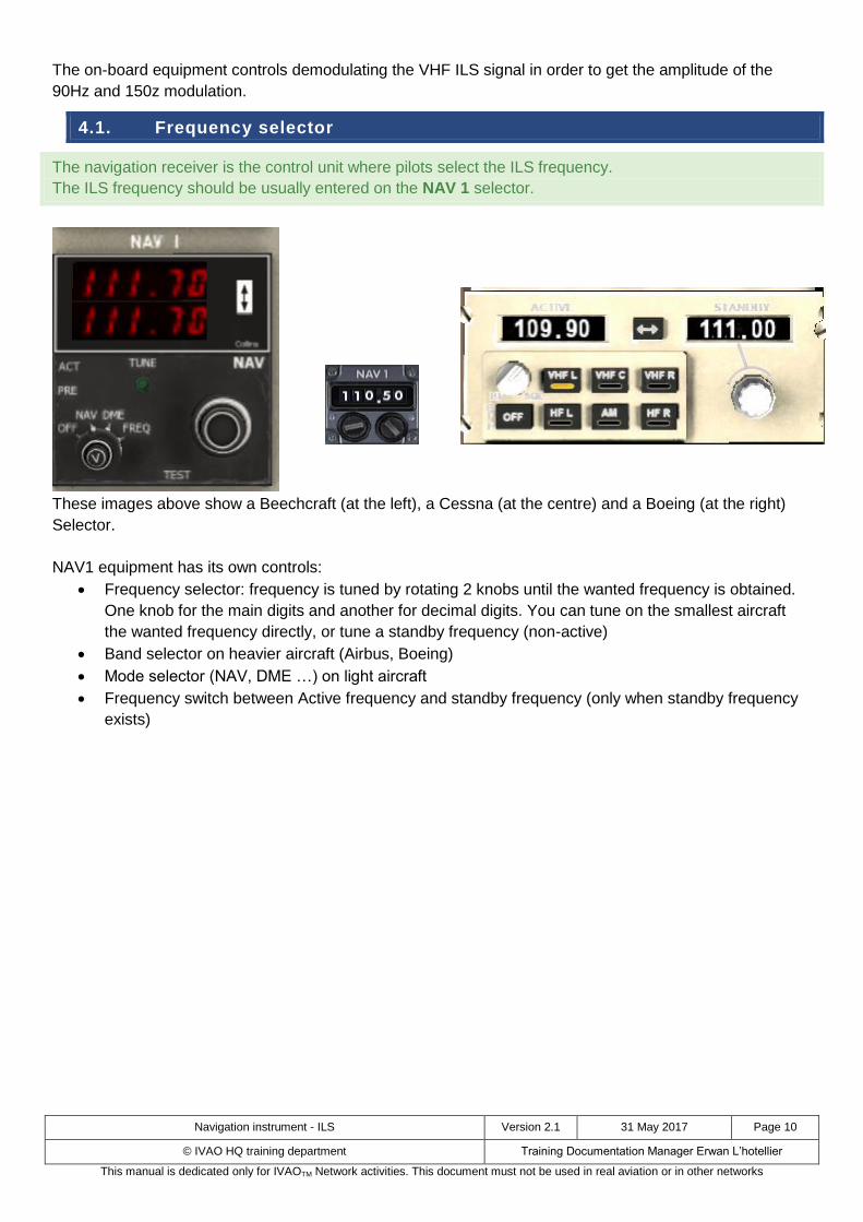
4.1. Frequency selector
The navigation receiver is the control unit where pilots select the ILS frequency.
The ILS frequency should be usually entered on the NAV 1 selector.
These images above show a Beechcraft (at the left), a Cessna (at the centre) and a Boeing (at the right)
Selector.
NAV1 equipment has its own controls:
Frequency selector: frequency is tuned by rotating 2 knobs until the wanted frequency is obtained.
One knob for the main digits and another for decimal digits. You can tune on the smallest aircraft
the wanted frequency directly, or tune a standby frequency (non-active)
Band selector on heavier aircraft (Airbus, Boeing)
Mode selector (NAV, DME …) on light aircraft
Frequency switch between Active frequency and standby frequency (only when standby frequency
exists)
Page 11
Navigation instrument - ILS Version 2.1 31 May 2017 Page 11
© IVAO HQ training department Training Documentation Manager Erwan L’hotellier
This manual is dedicated only for IVAOTM Network activities. This document must not be used in real aviation or in other networks
4.2. Indicator instruments
The ILS signal is analyzed by a receiver and displayed by:
A Course Deviation Indicator (CDI).
A Horizontal Situation Indicator (HSI)
An Electronic Horizontal Situation Indicator (EHSI) named Navigation Display (ND)
CDI (Cessna) HSI (Beechcraft) EHSI(Beechcraft) EHSI/ND(Boeing)
The localizer indicator is represented by a vertical indicator, using a vertical line, a vertical bar or a vertical
rectangle, which can move from left to right inside the instrument around the middle of the instrument
(centered position).
The glide path indicator is represented by
A horizontal indicator, using a horizontal line or a horizontal bar which can move from top to bottom
position inside the instrument around the middle of the instrument (centered position).
A small triangle or square next to a graduation bar on the right or left edge of the instrument
Page 12
Navigation instrument - ILS Version 2.1 31 May 2017 Page 12
© IVAO HQ training department Training Documentation Manager Erwan L’hotellier
This manual is dedicated only for IVAOTM Network activities. This document must not be used in real aviation or in other networks
5. Position of aircraft and display in the cockpit
5.1. Aircraft on localizer optimal path
The aircraft is exactly on the optimal path direct to the runway. No lateral shift is noticed.
The localizer vertical indicator on the navigation instrument is at the centre position.
5.2. Aircraft at the left of localizer optimal path
The aircraft is at the left of the optimal path direct to the runway. Lateral shift is noticed.
The localizer vertical indicator on the navigation instrument is on the right.
The centre of the instrument shall be taken as the aircraft direction and the localizer indicator represents
the optimal path.
In order to join the optimal path, the pilot shall turn to the right towards the indicator.
Page 13
Navigation instrument - ILS Version 2.1 31 May 2017 Page 13
© IVAO HQ training department Training Documentation Manager Erwan L’hotellier
This manual is dedicated only for IVAOTM Network activities. This document must not be used in real aviation or in other networks
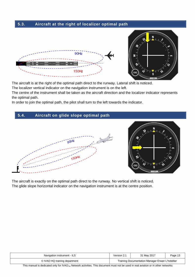
5.3. Aircraft at the right of localizer optimal path
The aircraft is at the right of the optimal path direct to the runway. Lateral shift is noticed.
The localizer vertical indicator on the navigation instrument is on the left.
The centre of the instrument shall be taken as the aircraft direction and the localizer indicator represents
the optimal path.
In order to join the optimal path, the pilot shall turn to the left towards the indicator.
5.4. Aircraft on glide slope optimal path
The aircraft is exactly on the optimal path direct to the runway. No vertical shift is noticed.
The glide slope horizontal indicator on the navigation instrument is at the centre position.
Page 14
Navigation instrument - ILS Version 2.1 31 May 2017 Page 14
© IVAO HQ training department Training Documentation Manager Erwan L’hotellier
This manual is dedicated only for IVAOTM Network activities. This document must not be used in real aviation or in other networks
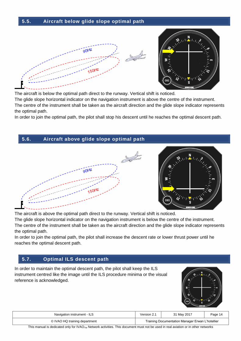
5.5. Aircraft below glide slope optimal path
The aircraft is below the optimal path direct to the runway. Vertical shift is noticed.
The glide slope horizontal indicator on the navigation instrument is above the centre of the instrument.
The centre of the instrument shall be taken as the aircraft direction and the glide slope indicator represents
the optimal path.
In order to join the optimal path, the pilot shall stop his descent until he reaches the optimal descent path.
5.6. Aircraft above glide slope optimal path
The aircraft is above the optimal path direct to the runway. Vertical shift is noticed.
The glide slope horizontal indicator on the navigation instrument is below the centre of the instrument.
The centre of the instrument shall be taken as the aircraft direction and the glide slope indicator represents
the optimal path.
In order to join the optimal path, the pilot shall increase the descent rate or lower thrust power until he
reaches the optimal descent path.
5.7. Optimal ILS descent path
In order to maintain the optimal descent path, the pilot shall keep the ILS
instrument centred like the image until the ILS procedure minima or the visual
reference is acknowledged.