44
NAVIO Surgical System Surgical Technique for Unicondylar Knee Replacement and Patellofemoral Arthroplasty
NAVIO Surgical SystemSurgical Technique forUnicondylar Knee Replacement andPatellofemoral Arthroplasty
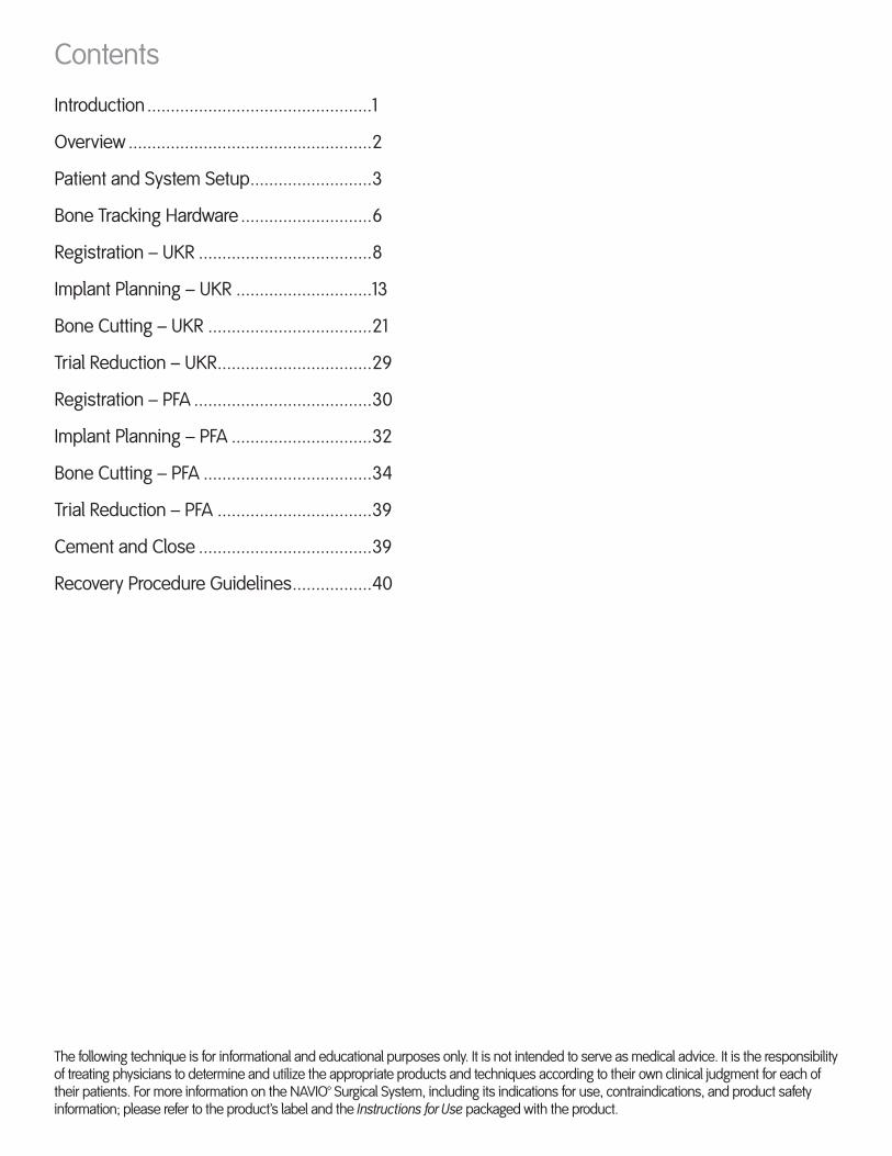
Contents
Introduction ................................................1
Overview ....................................................2
Patient and System Setup ..........................3
Bone Tracking Hardware ............................6
Registration – UKR .....................................8
Implant Planning – UKR .............................13
Bone Cutting – UKR ...................................21
Trial Reduction – UKR .................................29
Registration – PFA ......................................30
Implant Planning – PFA ..............................32
Bone Cutting – PFA ....................................34
Trial Reduction – PFA .................................39
Cement and Close .....................................39
Recovery Procedure Guidelines .................40
The following technique is for informational and educational purposes only. It is not intended to serve as medical advice. It is the responsibility of treating physicians to determine and utilize the appropriate products and techniques according to their own clinical judgment for each of their patients. For more information on the NAVIO™ Surgical System, including its indications for use, contraindications, and product safety information; please refer to the product’s label and the Instructions for Use packaged with the product.
1
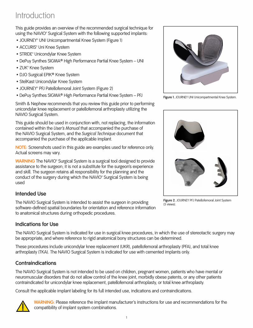
IntroductionThis guide provides an overview of the recommended surgical technique for using the NAVIO™ Surgical System with the following supported implants:• JOURNEY™ UNI Unicompartmental Knee System (Figure 1)• ACCURIS™ Uni Knee System• STRIDE™ Unicondylar Knee System• DePuy Synthes SIGMA® High Performance Partial Knee System – UNI• ZUK™ Knee System• DJO Surgical EPIK® Knee System• StelKast Unicondylar Knee System• JOURNEY™ PFJ Patellofemoral Joint System (Figure 2)• DePuy Synthes SIGMA® High Performance Partial Knee System – PFJ
Smith & Nephew recommends that you review this guide prior to performing unicondylar knee replacement or patellofemoral arthroplasty utilizing the NAVIO Surgical System.
This guide should be used in conjunction with, not replacing, the information contained within the User’s Manual that accompanied the purchase of the NAVIO Surgical System, and the Surgical Technique document that accompanied the purchase of the applicable implant.
NOTE: Screenshots used in this guide are examples used for reference only. Actual screens may vary.
WARNING The NAVIO™ Surgical System is a surgical tool designed to provide assistance to the surgeon; it is not a substitute for the surgeon’s experience and skill. The surgeon retains all responsibility for the planning and the conduct of the surgery during which the NAVIO™ Surgical System is being used
Intended Use
The NAVIO Surgical System is intended to assist the surgeon in providing software-defined spatial boundaries for orientation and reference information to anatomical structures during orthopedic procedures.
Indications for Use
The NAVIO Surgical System is indicated for use in surgical knee procedures, in which the use of stereotactic surgery may be appropriate, and where reference to rigid anatomical bony structures can be determined.
These procedures include unicondylar knee replacement (UKR), patellofemoral arthroplasty (PFA), and total knee arthroplasty (TKA). The NAVIO Surgical System is indicated for use with cemented implants only.
Contraindications
The NAVIO Surgical System is not intended to be used on children, pregnant women, patients who have mental or neuromuscular disorders that do not allow control of the knee joint, morbidly obese patents, or any other patients contraindicated for unicondylar knee replacement, patellofemoral arthroplasty, or total knee arthroplasty.
Consult the applicable implant labeling for its full intended use, indications and contraindications.
WARNING: Please reference the implant manufacturer’s instructions for use and recommendations for the compatibility of implant system combinations.
Figure 1. JOURNEY UNI Unicompartmental Knee System.
Figure 2. JOURNEY PFJ Patellofemoral Joint System (3 views).

2
OverviewNAVIO™ Surgical System
The NAVIO Surgical System is a surgical planning, navigation and intraoperative visualization system combined with a handheld smart instrument for bone sculpting.
The camera cart communicates the relative position of the handpiece, the femur, and the tibia (via rigid tracker arrays) to the computer cart (Figure 3).
The patient’s bone is prepared according to an intraoperative plan that combines soft-tissue balancing and collected anatomic information with controlled bone removal and predictable long-leg alignment.
The NAVIO Surgical System’s UKR and PFA applications can be separated into the following stages:
1. Patient and System Setup
2. Bone Tracking Hardware
3. Registration (UKR/PFA)
4. Implant Planning (UKR/PFA)
5. Bone Cutting (UKR/PFA)
6. Trial Reduction (UKR/PFA)
7. Cement and Close
This surgical technique guide is separated into the same stages for clarity.
NAVIO Instrument Kit
The NAVIO instrument kit (Figure 4) consists of a two-level tray that contains all of the required instrumentation for surgery using the NAVIO Surgical System.
NOTE: If the equipment breaks or fails during surgery, a sterile backup kit is on-site and can be unwrapped to replace a broken or dropped instrument.
Figure 3. Computer cart nested with camera cart (left); Handpiece (right).
Figure 4. Instrument kit.
Small PartsSterilization Case
Point Probe
T-HandleWrench
Handpiece Tracker Array
Tracker ArrayClamps (2)
Z KneeRetractor Anspach® eMAX® 2 Plus
Handpiece
Bone ScrewDriver
TibiaTracker Array
Fomon Rasp
FemurTracker Array
Tissue Protector
Guards
Handpiece
Long Attachment
3
Patient and System SetupPatient Setup
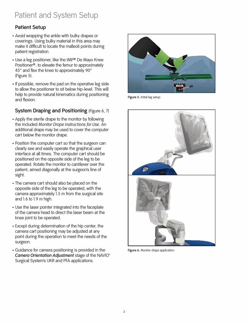
• Avoid wrapping the ankle with bulky drapes or coverings. Using bulky material in this area may make it difficult to locate the malleoli points during patient registration.
• Use a leg positioner, like the IMP® De Mayo Knee Positioner®, to elevate the femur to approximately 45° and flex the knee to approximately 90° (Figure 5).
• If possible, remove the pad on the operative leg side to allow the positioner to sit below hip-level. This will help to provide natural kinematics during positioning and flexion.
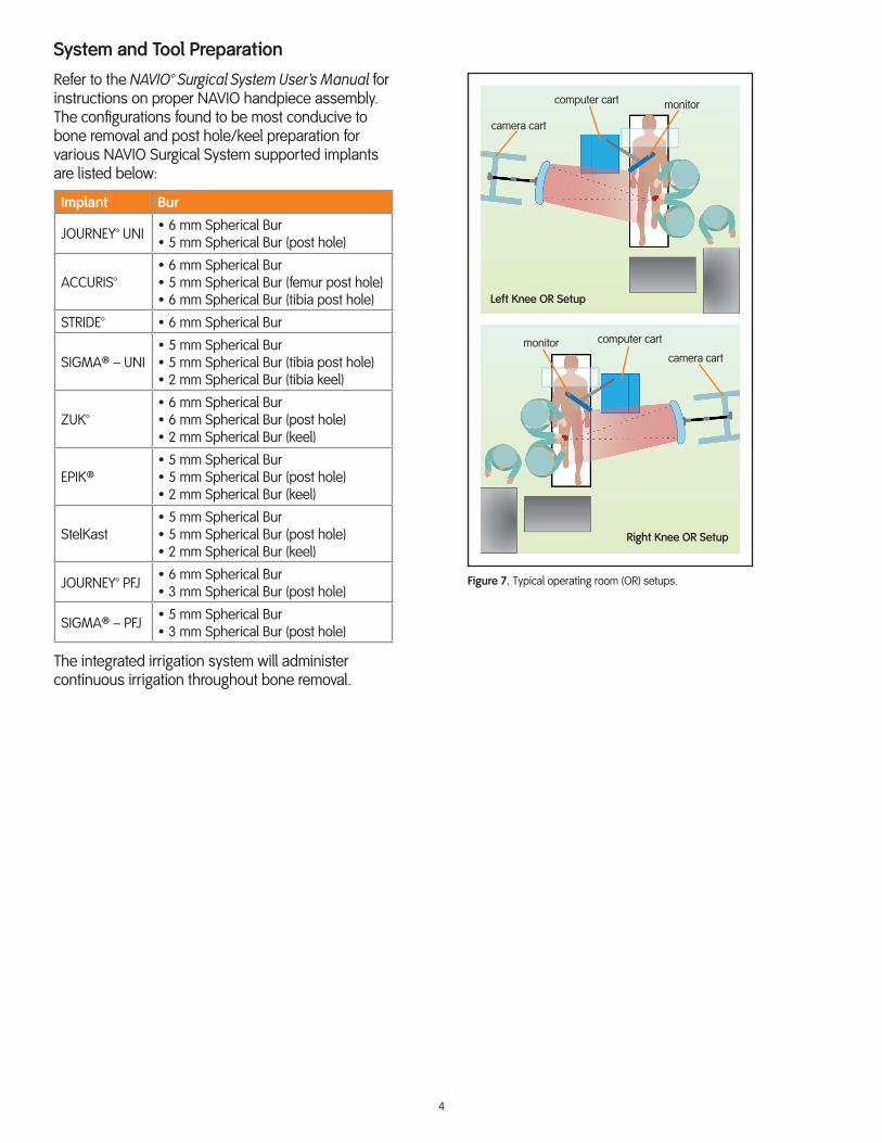
System Draping and Positioning (Figure 6, 7)
• Apply the sterile drape to the monitor by following the included Monitor Drape Instructions for Use. An additional drape may be used to cover the computer cart below the monitor drape.
• Position the computer cart so that the surgeon can clearly see and easily operate the graphical user interface at all times. The computer cart should be positioned on the opposite side of the leg to be operated. Rotate the monitor to cantilever over the patient, aimed diagonally at the surgeon’s line of sight.
• The camera cart should also be placed on the opposite side of the leg to be operated, with the camera approximately 1.5 m from the surgical site and 1.6 to 1.9 m high.
• Use the laser pointer integrated into the faceplate of the camera head to direct the laser beam at the knee joint to be operated.
• Except during determination of the hip center, the camera cart positioning may be adjusted at any point during the operation to meet the needs of the surgeon.
• Guidance for camera positioning is provided in the Camera Orientation Adjustment stage of the NAVIO™ Surgical System’s UKR and PFA applications.
Figure 5. Initial leg setup.
Figure 6. Monitor drape application.
4
System and Tool Preparation
Refer to the NAVIO™ Surgical System User’s Manual for instructions on proper NAVIO handpiece assembly. The configurations found to be most conducive to bone removal and post hole/keel preparation for various NAVIO Surgical System supported implants are listed below:
Implant Bur
JOURNEY™ UNI • 6 mm Spherical Bur• 5 mm Spherical Bur (post hole)
ACCURIS™• 6 mm Spherical Bur• 5 mm Spherical Bur (femur post hole)• 6 mm Spherical Bur (tibia post hole)
STRIDE™ • 6 mm Spherical Bur
SIGMA® – UNI• 5 mm Spherical Bur• 5 mm Spherical Bur (tibia post hole)• 2 mm Spherical Bur (tibia keel)
ZUK™• 6 mm Spherical Bur• 6 mm Spherical Bur (post hole)• 2 mm Spherical Bur (keel)
EPIK®• 5 mm Spherical Bur• 5 mm Spherical Bur (post hole)• 2 mm Spherical Bur (keel)
StelKast• 5 mm Spherical Bur• 5 mm Spherical Bur (post hole)• 2 mm Spherical Bur (keel)
JOURNEY™ PFJ • 6 mm Spherical Bur• 3 mm Spherical Bur (post hole)
SIGMA® – PFJ • 5 mm Spherical Bur• 3 mm Spherical Bur (post hole)
The integrated irrigation system will administer continuous irrigation throughout bone removal.
Figure 7. Typical operating room (OR) setups.
camera cart
computer cart
Left Knee OR Setup
Right Knee OR Setup
camera cart
computer cart
monitor
monitor

5
Exposure • For exposure recommendations specified by the implant system manufacturer, please consult their instructions for use and product documentation.
• Upon making the incision, carefully debride and inspect the joint. If any prominent spurs or osteophytes are present, especially in the area of the superior posterior femoral condyle, remove them with an osteotome or rongeur, as they could inhibit the leg motion.
• With medial compartment disease, osteophytes are typically found on the lateral aspect of the medial tibial eminence and anterior to the origin of the anterior cruciate ligament (ACL).
• Remove the intracondylar osteophytes to avoid impingement with the tibial spine or cruciate ligament; also remove the peripheral osteophytes that interfere with the collateral ligaments and capsule. In order to reliably assess mediolateral (ML) alignment and joint stability, it is crucial that all osteophytes are removed from the entire medial edges of the femur and tibia.
• Resect the deep meniscotibial layer of the medial capsule to provide access to any tibial osteophytes. Exposure also can be improved with excision of patellar osteophytes.
• Avoid release of the collateral ligament.
• With the patient in the supine position, ensure the knee is able to achieve 120° of flexion. A larger incision may be necessary to create sufficient exposure.
• While cutting the bone near the collateral ligament, insert a retractor between the tibia and the collateral ligament to protect the ligament from damage.
• Final debridement will be performed before component implantation.

6
Figure 9. Bone tracking arrays: Femur (top) and tibia (bottom). Keep the smaller end of the array toward the operative site.
Bone Tracking HardwarePlacing Tracking Hardware
The NAVIO™ Surgical System utilizes a two-pin bicortical fixation system, comprised of the tools pictured in Figure 8. These tools allow for the tracking arrays (Figure 9) to be fixed to the bone and for the tracking markers to be oriented towards the optical tracking camera. With the operative leg in 90° of flexion, utilize the following procedure.
WARNING: For bicompartmental surgery: If you intend to place both a patellofemoral prosthesis and a unicondylar prosthesis, ensure that the placement of the femoral bone hardware is far enough proximally on the femur, so as not to interfere with the camera’s visibility of the handpiece during either procedure.
Femur Tracker Array Placement
1. Percutaneously place the first bone pin one hand’s breadth (four fingers) superior to the patella in the center of the femur (Figure 10), leaving room for the handpiece tracker to be fully visible to the camera during preparation of the femur.
2. Slowly drill the bone pin into the femur, perpendicular to the bony surface, taking care to engage the opposing cortex and stop.
3. Utilize the tissue protector to mark the position of the second bone pin inferior to the initial placement. Engage the second pin with the bone through the tissue protector to ensure the pins are placed parallel to each other.
4. Slide the tracker array clamp (with the clamp hardware oriented towards the camera) over the two bone pins until the bottom of the clamp is within 1 cm of the patient’s skin. Take care not to place the clamp touching the skin.
5. Clamp the tracker array into the tracker array clamp along the length of the bar on the array. Place the smaller side of the tracker array closest to the operative site. Orient the markers towards the camera and slide the array away from the incision site.
6. Use the T-handle wrench to tighten the screw on the top of the tracker array clamp to secure the assembly. Be sure to confirm the array visibility on the Camera Orientation Adjustment screen before tightening the assembly.
Figure 8. Hardware (from left: bone pins, tissue protector, tracker array clamp).
Figure 10. Femur and tibia tracking array positions.
7
Tibia Tracker Array Placement (not applicable for PFA)
1. Percutaneously place the first bone pin one hand’s breadth (four fingers) inferior to the tibial tubercle on the medial side of the tibial crest (Figure 10).
2. Slowly drill the bone pin into the tibia, perpendicular to the bony surface, taking care to engage the opposing cortex and stop.
3. Refer to steps 3 through 6 of the Femur Tracker Array Placement section in this guide.
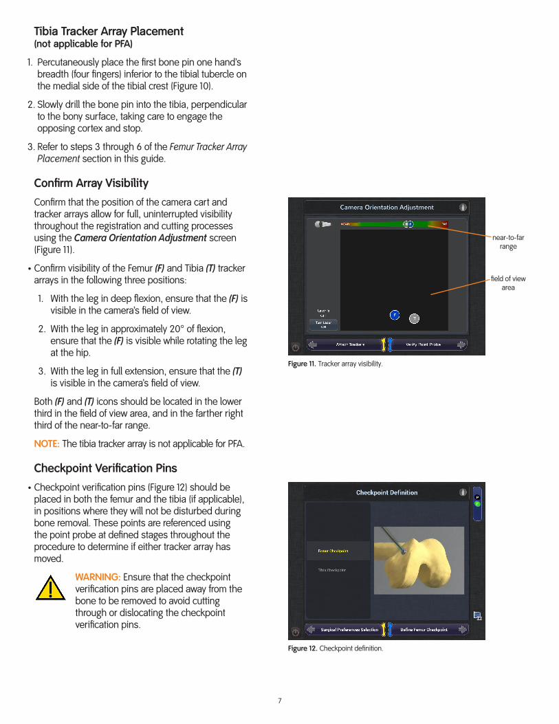
Confirm Array Visibility
Confirm that the position of the camera cart and tracker arrays allow for full, uninterrupted visibility throughout the registration and cutting processes using the Camera Orientation Adjustment screen (Figure 11).
• Confirm visibility of the Femur (F) and Tibia (T) tracker arrays in the following three positions:
1. With the leg in deep flexion, ensure that the (F) is visible in the camera’s field of view.
2. With the leg in approximately 20° of flexion, ensure that the (F) is visible while rotating the leg at the hip.
3. With the leg in full extension, ensure that the (T) is visible in the camera’s field of view.
Both (F) and (T) icons should be located in the lower third in the field of view area, and in the farther right third of the near-to-far range.
NOTE: The tibia tracker array is not applicable for PFA.
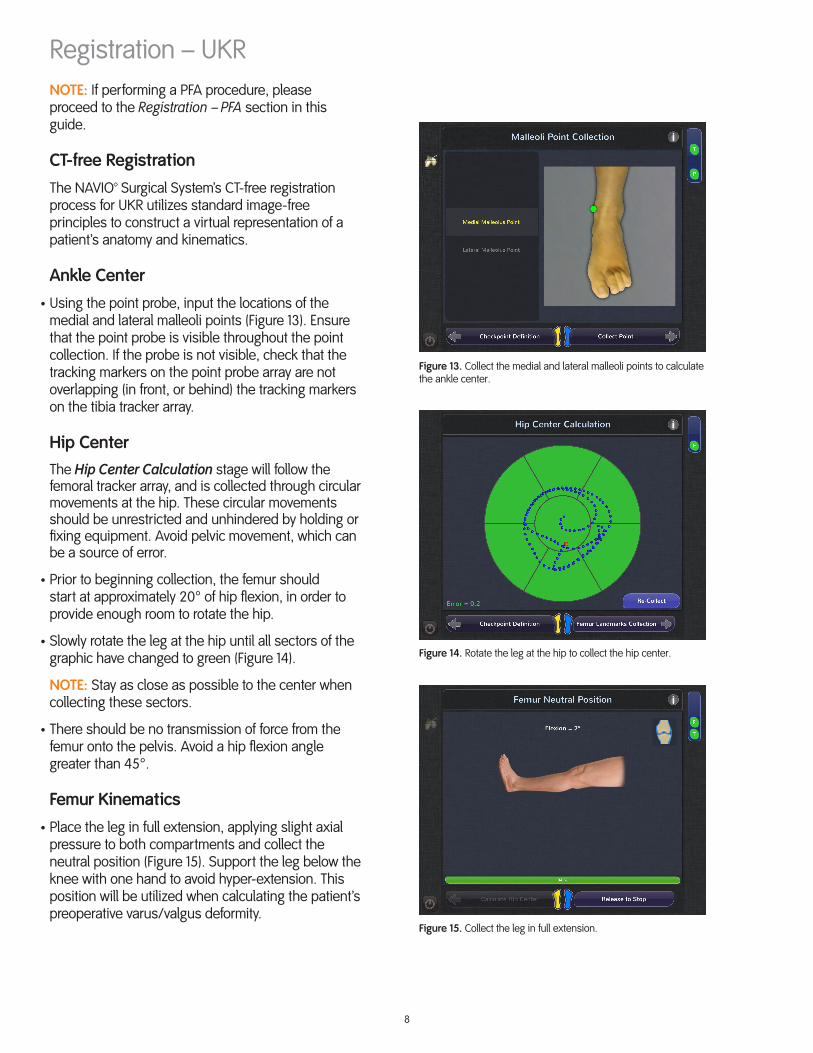
Checkpoint Verification Pins
• Checkpoint verification pins (Figure 12) should be placed in both the femur and the tibia (if applicable), in positions where they will not be disturbed during bone removal. These points are referenced using the point probe at defined stages throughout the procedure to determine if either tracker array has moved.
WARNING: Ensure that the checkpoint verification pins are placed away from the bone to be removed to avoid cutting through or dislocating the checkpoint verification pins.
Figure 11. Tracker array visibility.
Figure 12. Checkpoint definition.
near-to-farrange
field of viewarea
8
Registration – UKRNOTE: If performing a PFA procedure, please proceed to the Registration – PFA section in this guide.
CT-free Registration
The NAVIO™ Surgical System’s CT-free registration process for UKR utilizes standard image-free principles to construct a virtual representation of a patient’s anatomy and kinematics.
Ankle Center
• Using the point probe, input the locations of the medial and lateral malleoli points (Figure 13). Ensure that the point probe is visible throughout the point collection. If the probe is not visible, check that the tracking markers on the point probe array are not overlapping (in front, or behind) the tracking markers on the tibia tracker array.
Hip CenterThe Hip Center Calculation stage will follow the femoral tracker array, and is collected through circular movements at the hip. These circular movements should be unrestricted and unhindered by holding or fixing equipment. Avoid pelvic movement, which can be a source of error.
• Prior to beginning collection, the femur should start at approximately 20° of hip flexion, in order to provide enough room to rotate the hip.
• Slowly rotate the leg at the hip until all sectors of the graphic have changed to green (Figure 14).
NOTE: Stay as close as possible to the center when collecting these sectors.
• There should be no transmission of force from the femur onto the pelvis. Avoid a hip flexion angle greater than 45°.
Femur Kinematics
• Place the leg in full extension, applying slight axial pressure to both compartments and collect the neutral position (Figure 15). Support the leg below the knee with one hand to avoid hyper-extension. This position will be utilized when calculating the patient’s preoperative varus/valgus deformity.
Figure 13. Collect the medial and lateral malleoli points to calculate the ankle center.
Figure 14. Rotate the leg at the hip to collect the hip center.
Figure 15. Collect the leg in full extension.

9
• The next step will record normal flexion motion and calculate the femoral kinematic rotational axis. Slowly move the leg through a normal (unstressed) range-of-motion to maximum flexion (Figure 16). Flex and extend the leg until all of the green bars read fully green (100%).
Ligament Tension
• Apply constant stress to the operative ligament (e.g. valgus stress to the medial collateral ligament, MCL, when performing a medial UKR procedure) and collect the data throughout flexion. Input can either be continuous (Figure 17) which requires constant application of stress throughout flexion, or in discrete poses (Figure 18) which some users find easier to stabilize a flexion position and record the ligament stress.
This data is collected for use during the Gap Planning stage. You want to identify how much room the ligaments have. This will inform how much gap (laxity) will be built into the joint balance.
NOTE: Do not over-tension ligaments and force alignment into the unresurfaced compartment of the knee. Varus knees should be kept in slight varus, and valgus knees in slight valgus. Avoid correcting beyond neutral.
Figure 16. Input the femoral kinematic axis.
Figure 18. Stressed ROM Collection screen with discrete position input.
Figure 17. Stressed ROM (range of motion) Collection screen with continuous input.

10
Figure 19. Femur landmark point collection for UKR.
Femur Landmarks – UKR
There are four femoral landmark points to collect for UKR (Figure 19). These points are to be used as visual references during Implant Planning.
Using the point probe, collect the following:
• Tidemark PointThe Tidemark point is the expected anterior termination of the femoral implant component. This point can be identified with the leg in full extension, referencing where the anterior tibia meets the femoral condyle.
• Knee CenterCollect the center of the knee, which will be referenced as part of the HKA (hip-knee-ankle) weight bearing axis. This point is typically found in the trochlear groove, anterior to the posterior cruciate ligament attachment.
• Most Distal PointPlace the probe on the most distal part of the femoral condyle, centered mediolaterally. During Implant Planning, the software will use the most distal point to center the initial implant placement.
• Most Posterior PointHyper-flex the leg to access the most posterior point on the femoral condyle, marking the inflection point as the condyle curves posterior. The software will use the Tidemark and most posterior points to present an initial implant component size.
Femoral Surface Mapping
The Femur Free Collection stage (Figure 20) offers a visualization of the previously collected femoral mechanical axis and rotational axis (blue lines), as well as the discrete femur landmark points (yellow dots).
• Digitize the femoral condyle by moving the point probe over the entire surface, while holding down the footpedal. Use both hands to ensure constant contact of the point probe with the bone surface. Start by outlining the surface you want to digitize, then fill in the entire surface.
• You must input enough information into the system to appropriately localize the implant during planning.
• Hyperflex the leg to map the posterior portion. Manipulate the touchscreen to view the collected virtual bone surface in 3D (three dimensions).
Figure 20. The software presents a virtual representation of the bone surface, generated from the collected free points. Manipulate the visualization to view in 3D.
11
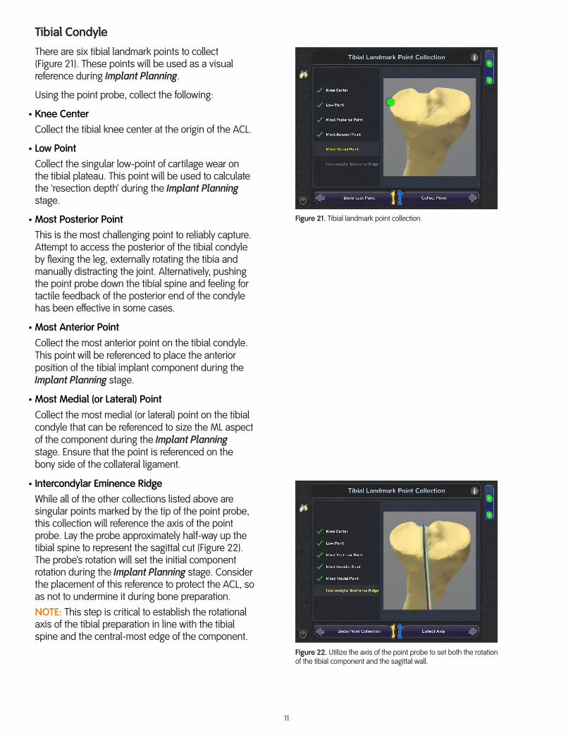
Tibial Condyle
There are six tibial landmark points to collect (Figure 21). These points will be used as a visual reference during Implant Planning.
Using the point probe, collect the following:
• Knee CenterCollect the tibial knee center at the origin of the ACL.
• Low PointCollect the singular low-point of cartilage wear on the tibial plateau. This point will be used to calculate the ‘resection depth’ during the Implant Planning stage.
• Most Posterior PointThis is the most challenging point to reliably capture. Attempt to access the posterior of the tibial condyle by flexing the leg, externally rotating the tibia and manually distracting the joint. Alternatively, pushing the point probe down the tibial spine and feeling for tactile feedback of the posterior end of the condyle has been effective in some cases.
• Most Anterior PointCollect the most anterior point on the tibial condyle. This point will be referenced to place the anterior position of the tibial implant component during the Implant Planning stage.
• Most Medial (or Lateral) PointCollect the most medial (or lateral) point on the tibial condyle that can be referenced to size the ML aspect of the component during the Implant Planning stage. Ensure that the point is referenced on the bony side of the collateral ligament.
• Intercondylar Eminence RidgeWhile all of the other collections listed above are singular points marked by the tip of the point probe, this collection will reference the axis of the point probe. Lay the probe approximately half-way up the tibial spine to represent the sagittal cut (Figure 22). The probe’s rotation will set the initial component rotation during the Implant Planning stage. Consider the placement of this reference to protect the ACL, so as not to undermine it during bone preparation.NOTE: This step is critical to establish the rotational axis of the tibial preparation in line with the tibial spine and the central-most edge of the component.
Figure 21. Tibial landmark point collection.
Figure 22. Utilize the axis of the point probe to set both the rotation of the tibial component and the sagittal wall.

12
Tibial Condyle Surface Mapping
The Tibia Free Collection stage (Figure 23) offers a visualization of the tibial mechanical axis and rotational axis previously collected (blue lines) as well as these discrete tibial landmark points (yellow dots).
• Digitize the tibial condyle similarly to the Femur Free Collection stage.
• Define anterior and medial edges of the condyle as far posterior as is accessible. Map the intercondylar eminence along the axis of the point probe. Fill in the surface, moving anterior to posterior as space allows.
• Externally rotate the tibia, apply valgus stress, or hyperflex to access additional portions of the articulating condylar anatomy. Collect points approximately 8 to 10 mm down the anterior and medial side of the condyle, so that overhang can be identified during the Implant Planning stage. It is important to work the probe around the medial side of the bone, past the medial point, in order to digitize the anatomic shape for component sizing during the Implant Planning stage.
Figure 23. Digitize the tibial condyle for utilization during the Implant Planning stage; you can always return to this stage to define more points if needed.

13
Implant Planning – UKRThe Implant Planning stage for UKR presents you with a virtual representation of the patient’s femoral and tibial anatomy. It visualizes soft-tissue ligament tension to aid in joint balance and demonstrates component-on-component contact points for load transfer and wear patterns.
There are two view modes for prosthesis placement: Solid Surface view (Figure 24), and Cross Section view (Figure 25).
The Solid Surface view allows you to manipulate these views in 3D space and they will always snap back to their original plane of view.
The Cross Section view allows you to drag a finger vertically over the active window to view cross sectional slices of the bone in either the sagittal, coronal or transverse planes, and visualize the position of the implant in that particular slice within the plane.
The goal of the Implant Planning stage is to allow you to localize the components and balance key metrics along the way. You should be able to visualize the postoperative X-Ray before any cuts are made.
There are three steps in the Implant Planning stage for UKR:
• Prosthesis Sizing and Placement• Gap Planning• Component M-L Position Adjustment
Figure 24. Femoral prosthesis placement in Solid Surface view.
Figure 25. Femoral prosthesis placement in Cross Section view.
14
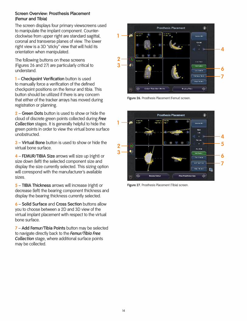
Screen Overview: Prosthesis Placement (Femur and Tibia)The screen displays four primary viewscreens used to manipulate the implant component. Counter-clockwise from upper right are standard sagittal, coronal and transverse planes of view. The lower right view is a 3D “sticky” view that will hold its orientation when manipulated.
The following buttons on these screens (Figures 26 and 27) are particularly critical to understand.
1 – Checkpoint Verification button is used to manually force a verification of the defined checkpoint positions on the femur and tibia. This button should be utilized if there is any concern that either of the tracker arrays has moved during registration or planning.
2 – Green Dots button is used to show or hide the cloud of discrete green points collected during Free Collection stages. It is generally helpful to hide the green points in order to view the virtual bone surface unobstructed.
3 – Virtual Bone button is used to show or hide the virtual bone surface.
4 – FEMUR/TIBIA Size arrows will size up (right) or size down (left) the selected component size and display the size currently selected. This sizing option will correspond with the manufacturer’s available sizes.
5 – TIBIA Thickness arrows will increase (right) or decrease (left) the bearing component thickness and display the bearing thickness currently selected.
6 – Solid Surface and Cross Section buttons allow you to choose between a 2D and 3D view of the virtual implant placement with respect to the virtual bone surface.
7 – Add Femur/Tibia Points button may be selected to navigate directly back to the Femur/Tibia Free Collection stage, where additional surface points may be collected.
Figure 26. Prosthesis Placement (Femur) screen.
Figure 27. Prosthesis Placement (Tibia) screen.
1
23
4
67
1
23
54
67

15
Step 1. Prosthesis Sizing and Placement
Femoral ComponentThe NAVIO™ Surgical System software will provide a starting size and initial placement of the femoral component, utilizing the landmark points that were collected during the Registration stage. The default coronal alignment of the femoral component is 0° relative to the mechanical axis of the femur, and can be adjusted to accommodate your preference. From the initial placement, you have the ability to adjust the size and placement of the component.
When localizing the femoral component on the digitized surface, the following are key metrics to review:
• In the sagittal plane of view, confirm that the size provides full coverage from the Tidemark point to the posterior point.
• For a medial surgery, the posterior surface of the femoral implant should be approximately 1.5 mm anterior of the native posterior cartilage in order to achieve the target flexion gap in Gap Planning. This helps to avoid an excessively tight gap in flexion. For a lateral surgery, position the component flush with the posterior cartilage which is generally well preserved.
• Adjust component flexion (use the Rotation arrows in the viewscreen) to achieve desired anterior transition within the virtual condylar surface (Figure 28). The supported implants are designed to be implanted at the following degrees of flexion:
Implant ° Flexion Definition
JOURNEY™ UNI 45°Angle between the posterior femoral implant post and the femur mechanical axis.
ACCURIS™ 0° Distal cut is perpendicular to the femur mechanical axis.
STRIDE™ 25° Angle of the post holes to the femur mechanical axis.
ZUK™ 25°Angle between the posterior femoral implant post and the femur mechanical axis.
EPIK® 10° Angle of the post holes to the femur mechanical axis.
StelKast 0° Angle of the post holes to the femur mechanical axis.
SIGMA® 0°
Angle between the axis perpendicular to the distal portion of the femoral implant and the femur mechanical axis.
Figure 28. Confirm proper anterior transition to minimize risk of patella impingement (upper right, sagittal plane of view).

16
NOTE (For SIGMA): The anterior tip of the SIGMA High Performance Partial Knee femoral component should be inset approximately 3 mm beneath the native femur cartilage surface. For reference, it is important to note that the SIGMA High Performance Partial Knee mechanical instruments are designed to make the distal femoral resection perpendicular to the intramedullary (IM) axis of the femur through constrained flexing of the knee, and resecting with the guidance of the tibial preparation.
NOTE (For ZUK): To plan the ZUK implant in a manner similar to the manual instrumentation, plan the posterior femoral component flush with the native cartilage and then move the component anteriorly 2 mm. Four clicks is approximately equivalent to 2 mm on the planning screens. At this stage, confirm that the anterior portion of the femoral component is in the desired position in relation to the Tidemark point.
• If the virtual bone surface is behind the implant (on the cement side, as opposed to the articulating side) this is indicative of a shallow bone-resection, or little-to-no bone/cartilage resection, and you should consider burying the component deeper.
• Utilize the transverse plane of view (lower left) to ensure that the component is localized properly on the condyle (Figure 29). The software will provide the starting position for the implant component centered on the distal landmark point that was collected on the femur during the Registration stage. For condyles that are wider than the implant, the prosthesis should be biased laterally (or medially) to optimize tracking on the tibial component.
• Confirm that the component is not overhanging medially or laterally, which will be evident if the dark gray of the virtual implant is breaking through the virtual bone surface. If required, you can apply external rotation to the component using the Rotation arrows in the active viewscreen. The software will indicate how much rotation you are applying.NOTE: The default rotational value is 0°. Refer to the applicable implant Surgical Technique for recommended implant component rotational constraints.NOTE (For SIGMA):The allowance for angular orientation variation between the femur and the tibia with the SIGMA High Performance Partial Knee components is ± 10°.
Figure 29. Confirm proper positioning (lower left, transverse plane of view). Distal landmark point is circled.
17
• You may also evaluate implant placement using the Cross Section view. Switch to this view by selecting Cross Section on the right side of the screen. Activate the desired plane of view and slide a finger vertically on the viewscreen to navigate through cross sectional views.
NOTE: If at any point during Implant Planning you feel as if the current virtualization of the femoral condyle is not sufficient, press the Add Femur Points button in the lower right portion of the screen. Collect additional points in Femur Free Collection in the deficient areas. Continuing forward from this screen will bring you right back to the Implant Planning stage.
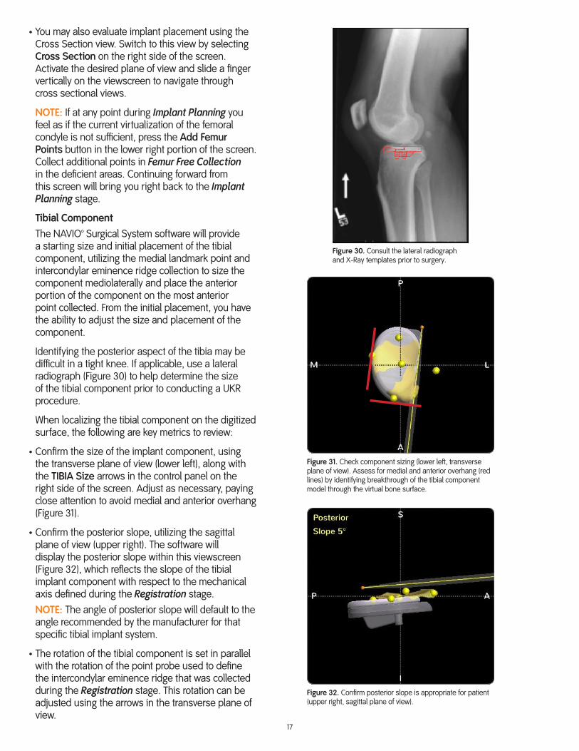
Tibial ComponentThe NAVIO™ Surgical System software will provide a starting size and initial placement of the tibial component, utilizing the medial landmark point and intercondylar eminence ridge collection to size the component mediolaterally and place the anterior portion of the component on the most anterior point collected. From the initial placement, you have the ability to adjust the size and placement of the component.
Identifying the posterior aspect of the tibia may be difficult in a tight knee. If applicable, use a lateral radiograph (Figure 30) to help determine the size of the tibial component prior to conducting a UKR procedure.
When localizing the tibial component on the digitized surface, the following are key metrics to review:
• Confirm the size of the implant component, using the transverse plane of view (lower left), along with the TIBIA Size arrows in the control panel on the right side of the screen. Adjust as necessary, paying close attention to avoid medial and anterior overhang (Figure 31).
• Confirm the posterior slope, utilizing the sagittal plane of view (upper right). The software will display the posterior slope within this viewscreen (Figure 32), which reflects the slope of the tibial implant component with respect to the mechanical axis defined during the Registration stage.NOTE: The angle of posterior slope will default to the angle recommended by the manufacturer for that specific tibial implant system.
• The rotation of the tibial component is set in parallel with the rotation of the point probe used to define the intercondylar eminence ridge that was collected during the Registration stage. This rotation can be adjusted using the arrows in the transverse plane of view.
Figure 32. Confirm posterior slope is appropriate for patient (upper right, sagittal plane of view).
Figure 31. Check component sizing (lower left, transverse plane of view). Assess for medial and anterior overhang (red lines) by identifying breakthrough of the tibial component model through the virtual bone surface.
Figure 30. Consult the lateral radiograph and X-Ray templates prior to surgery.

18
• Confirm that the tibial component is flush with the bone anteriorly, utilizing the sagittal plane of view (upper right).
• The tibial component will default to the thinnest bearing. This thickness can be adjusted by changing the component using the TIBIA Thickness arrows in the control panel on the right side of the screen. The component position will default to place the top of the bearing 3 mm above the previously defined low point collected on the tibia during the Registration stage. Using the arrows in that viewscreen, you may move the component superior, decreasing resection depth.NOTE (For Inlay Style Uni Implants): Refer to the applicable implant Surgical Technique for recommended resection depth.
• You may also evaluate implant placement using the Cross Section view. Switch to this view by selecting Cross Section on the right side of the screen. Activate the desired plane of view and slide a finger vertically on the viewscreen to navigate through cross sectional views.
NOTE: If at any point during Implant Planning you feel as if the current virtualization of the tibial condyle is not sufficient, press the Add Tibia Points button in the lower right portion of the screen. Collect additional points in Tibia Free Collection in deficient areas. Continuing forward from this screen will bring you right back to the Implant Planning stage.
Step 2. Gap Planning This stage provides you with the ability to balance soft-tissue laxity (gap) throughout the patient’s range of motion. The soft-tissue gap planning is predicated on the stressed range of motion input from the Registration stage. During the Stressed ROM (range of motion) stage, you applied valgus stress (for a medial condyle) to the operative-side collateral ligament in order to plot how much ligament laxity the compartment has.
• The Gap Planning screen (Figure 33) has four interactive viewscreens for translating and rotating the components with respect to the patient’s virtualized joint. Beneath those viewscreens is a graph from 0 through 120° of flexion. The x-axis represents the flexion (degrees). The y-axis represents millimeters of either the relative gap/laxity (+) or the overlap/tightness (-).
• The orange graph line represents discrete points of flexion input from the Stressed ROM screen. If an orange point is above the zero line, this represents “Gap” in the joint. If an orange point is below the zero line, this represents “Overlap” of the theoretical joint. You want to avoid overlap, which may over-stuff the joint and load the contralateral compartment.
Figure 33. Run a finger over the flexion gap graph at bottom of screen to visualize the theoretical articulation of the femur and tibia implant components throughout the ROM in the viewscreens.
Ligamentbutton

19
• Pressing the Ligament button to the left of the flexion gap graph will switch the focus of the graph from the orange line to the blue line. The blue line represents the unstressed ROM collected during the Registration stage. By displaying both of these lines on top of one another on the graph, you can visually identify how much laxity was mapped into the joint through the Stressed ROM Collection. If the orange line meets the blue line, then this indicates you were unable to apply ligament stress to the knee at this section of flexion.
NOTE: It is important to balance the graph with the orange Stressed ROM collection line, not the blue Unstressed ROM collection line.
• Additionally, you can activate a virtualization of the femur and tibia components articulating against each other in the viewscreens by dragging a finger across the flexion gap graph.
• The goal is to balance the soft tissue gap throughout flexion, ideally aiming for a relatively flat line and 1 to 2 mm of gap/laxity (Figure 34).
• Manipulate the position and orientation of the implant components so that the resulting flexion gap graph is generally flat and positioned 1 to 2 mm above the zero line in early to mid-flexion. In deeper flexion (> 90°), the resulting gap should be slightly increased. This indicates an even gap throughout flexion (Figures 35 and 36).
• Confirm that the implant resection is appropriate, rotating the femoral component to view the backside. Any visible virtual bone surface on the underside of the implant indicates a shallow resection. Adjustments to femoral flexion should be carefully considered against prior considerations regarding anterior fit and alignment to the IM axis.
Ligament Balancing Manipulations
Scenario Manipulation
Balance is tight throughout flexion. Move tibial component inferior and/or reduce thickness.
Balance is loose throughout flexion. Move tibial component superior and/or increase thickness.
Balance is tight in extension and loose in flexion. Move the femoral component posterior,orreduce femoral component flexion.
Balance is tight in flexion and loose in extension. Move femoral component anterior,orincrease femoral component flexion,orincrease posterior slope of tibial component (ideally no more than 7°) and move tibial component inferior.
Balance is tight in mid-flexion and loose in extension and deep flexion.
Move femoral component anterior and superior.
Figure 35. Adjusting the tibial depth resection will increase or decrease the gap from extension to flexion.
Figure 34. The final flexion gap graph should reflect an appropriate level of laxity in the joint throughout flexion. There may be a characteristic mid-flexion tightness.
Figure 36. Adjusting the femoral component in the anteroposterior (AP) direction will adjust flexion gap.
20
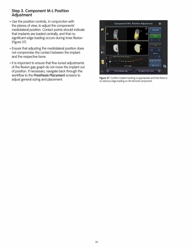
Step 3. Component M-L Position Adjustment
• Use the position controls, in conjunction with the planes of view, to adjust the components’ mediolateral position. Contact points should indicate that implants are loaded centrally, and that no significant edge loading occurs during knee flexion (Figure 37).
• Ensure that adjusting the mediolateral position does not compromise the contact between the implant and the respective bone.
• It is important to ensure that fine-tuned adjustments of the flexion gap graph do not move the implant out of position. If necessary, navigate back through the workflow to the Prosthesis Placement screens to adjust general sizing and placement. Figure 37. Confirm implant tracking is appropriate and that there is
no obvious edge loading on the femoral component.
21
Bone Cutting – UKRBone Preparation
During bone preparation, you will execute the surgical plan as generated from the Implant Planning stage.
To make adjustments to the plan at any time during the cutting process, select the Back to Planning button. After making the adjustments, you may move forward again to the Bone Removal stage to continue bone preparation.
Setup
The following are tips for using the NAVIO™ Surgical System to prepare the bone:
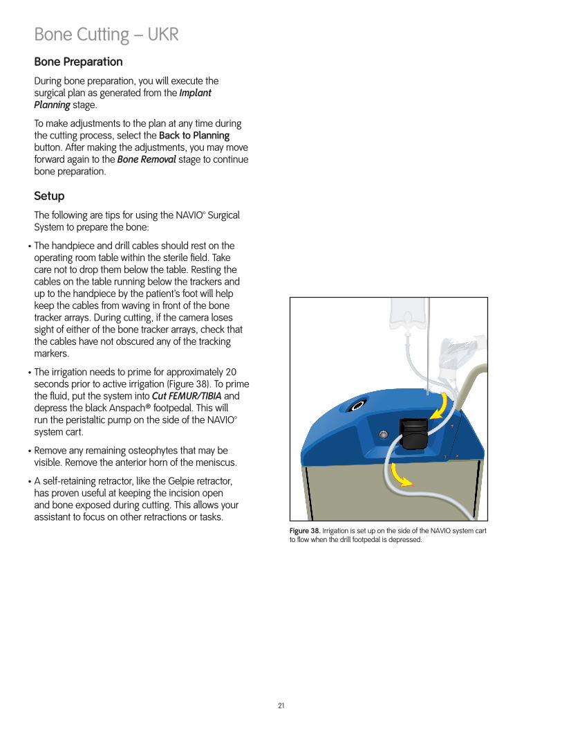
• The handpiece and drill cables should rest on the operating room table within the sterile field. Take care not to drop them below the table. Resting the cables on the table running below the trackers and up to the handpiece by the patient’s foot will help keep the cables from waving in front of the bone tracker arrays. During cutting, if the camera loses sight of either of the bone tracker arrays, check that the cables have not obscured any of the tracking markers.
• The irrigation needs to prime for approximately 20 seconds prior to active irrigation (Figure 38). To prime the fluid, put the system into Cut FEMUR/TIBIA and depress the black Anspach® footpedal. This will run the peristaltic pump on the side of the NAVIO™ system cart.
• Remove any remaining osteophytes that may be visible. Remove the anterior horn of the meniscus.
• A self-retaining retractor, like the Gelpie retractor, has proven useful at keeping the incision open and bone exposed during cutting. This allows your assistant to focus on other retractions or tasks.
Figure 38. Irrigation is set up on the side of the NAVIO system cart to flow when the drill footpedal is depressed.
22
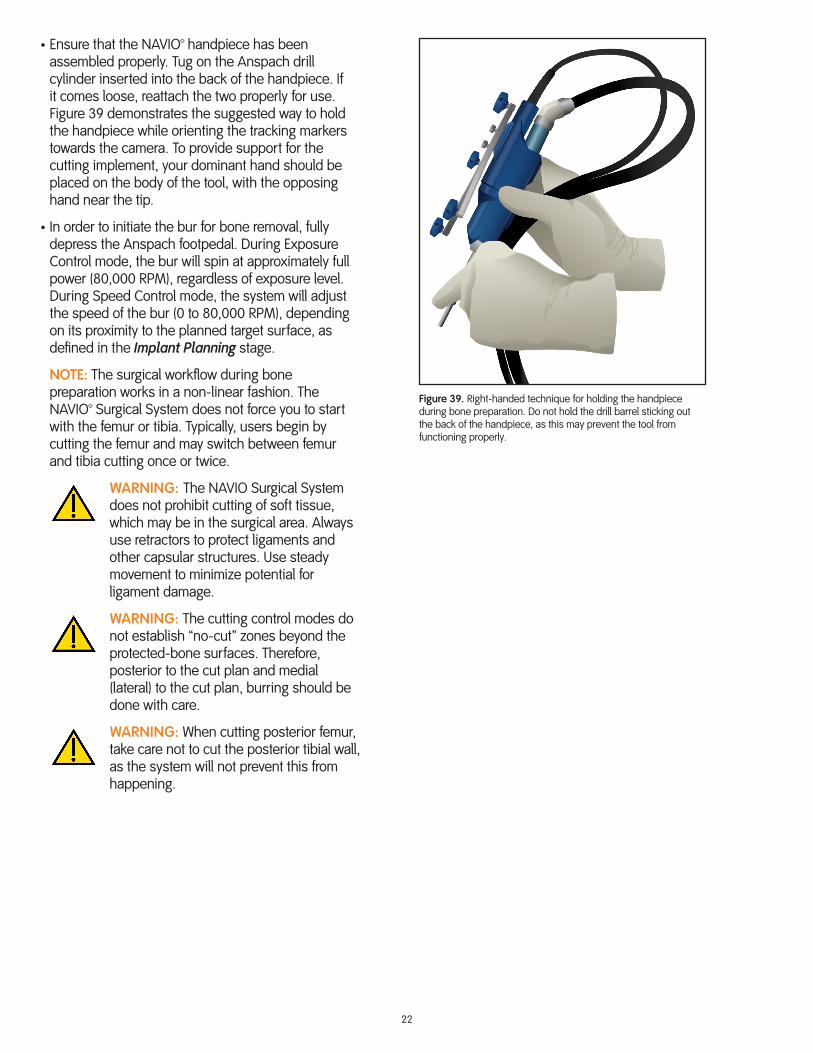
• Ensure that the NAVIO™ handpiece has been assembled properly. Tug on the Anspach drill cylinder inserted into the back of the handpiece. If it comes loose, reattach the two properly for use. Figure 39 demonstrates the suggested way to hold the handpiece while orienting the tracking markers towards the camera. To provide support for the cutting implement, your dominant hand should be placed on the body of the tool, with the opposing hand near the tip.
• In order to initiate the bur for bone removal, fully depress the Anspach footpedal. During Exposure Control mode, the bur will spin at approximately full power (80,000 RPM), regardless of exposure level. During Speed Control mode, the system will adjust the speed of the bur (0 to 80,000 RPM), depending on its proximity to the planned target surface, as defined in the Implant Planning stage.
NOTE: The surgical workflow during bone preparation works in a non-linear fashion. The NAVIO™ Surgical System does not force you to start with the femur or tibia. Typically, users begin by cutting the femur and may switch between femur and tibia cutting once or twice.
WARNING: The NAVIO Surgical System does not prohibit cutting of soft tissue, which may be in the surgical area. Always use retractors to protect ligaments and other capsular structures. Use steady movement to minimize potential for ligament damage.
WARNING: The cutting control modes do not establish “no-cut” zones beyond the protected-bone surfaces. Therefore, posterior to the cut plan and medial (lateral) to the cut plan, burring should be done with care.
WARNING: When cutting posterior femur, take care not to cut the posterior tibial wall, as the system will not prevent this from happening.
Figure 39. Right-handed technique for holding the handpiece during bone preparation. Do not hold the drill barrel sticking out the back of the handpiece, as this may prevent the tool from functioning properly.

23
Screen Overview
Figure 40 shows a typical Bone Removal screen for UKR with the following icons/buttons identified:
1 – Checkpoint Verification button is used to manually force a verification of the defined checkpoint positions on the femur and tibia.
2 – Change Bur button is used to update the system about a change you made to the selected bur size.
3 – Back to Planning button returns you to the Gap Planning screen to make adjustments to the prosthesis placement plan.
4 – Tool’s Eye View displays “what the tool sees,” similar to a scope view, and it is continuously active.
5 – Isometric Cut Model can be manipulated based on user view preference.
6 – Control Mode Indicator displays which control mode (exposure or speed) you are currently using. Pressing the button will allow you to change the selected control mode.
7 – Tracker Array Status will show if a tracker array is visible to the camera (green) or obstructed (black). Check this status indicator if the system is not cutting, as it will prevent bone cutting when an array important to the action is obstructed from view. You may also press this icon to present a Field of View screen to confirm tracker array visibility within the camera’s field of view.
8 – Tool’s Eye View button is used to toggle between bird’s-eye view (default view) and tool’s eye view.
9 – Color Depth Legend button may be toggled on or off. Activate the legend to view colors corresponding to depth (mm) to target surface.
10 – Crosshair View button may be toggled on or off. Activate this view when preparing fixation features, like post-holes.
11 – Virtual Trial Implant button may be used to activate a virtual implant that will be shown on the main viewscreen. This is useful to confirm progress to the cut plan, and to check for overhang of implant on bone.
12 – Screenshot button can be used at any time to capture a screenshot of whatever is currently on the monitor. The screenshot will be saved for access when archiving the patient.
13 – Cutting Mode (Refine FEMUR, Cut FEMUR, Refine TIBIA, Cut TIBIA) highlights the current mode that you are using, and can be used to navigate to other modes.
Figure 40. Typical Bone Removal screen.
2
10
3
11
1
12
7
4
5 6
13
98
24
Refine Femur
Prior to Bone Removal, you are encouraged to enter the Refine FEMUR mode.
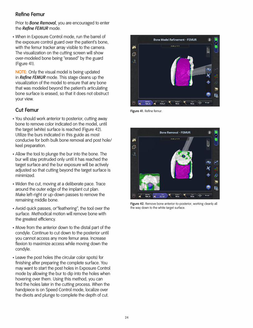
• When in Exposure Control mode, run the barrel of the exposure control guard over the patient’s bone, with the femur tracker array visible to the camera. The visualization on the cutting screen will show over-modeled bone being “erased” by the guard (Figure 41).
NOTE: Only the visual model is being updated in Refine FEMUR mode. This stage cleans up the visualization of the model to ensure that any bone that was modeled beyond the patient’s articulating bone surface is erased, so that it does not obstruct your view.
Cut Femur
• You should work anterior to posterior, cutting away bone to remove color indicated on the model, until the target (white) surface is reached (Figure 42). Utilize the burs indicated in this guide as most conducive for both bulk bone removal and post hole/keel preparation.
• Allow the tool to plunge the bur into the bone. The bur will stay protruded only until it has reached the target surface and the bur exposure will be actively adjusted so that cutting beyond the target surface is minimized.
• Widen the cut, moving at a deliberate pace. Trace around the outer edge of the implant cut plan. Make left-right or up-down passes to remove the remaining middle bone.
• Avoid quick passes, or“feathering”, the tool over the surface. Methodical motion will remove bone with the greatest efficiency.
• Move from the anterior down to the distal part of the condyle. Continue to cut down to the posterior until you cannot access any more femur area. Increase flexion to maximize access while moving down the condyle.
• Leave the post holes (the circular color spots) for finishing after preparing the complete surface. You may want to start the post holes in Exposure Control mode by allowing the bur to dip into the holes when hovering over them. Using this method, you can find the holes later in the cutting process. When the handpiece is on Speed Control mode, localize over the divots and plunge to complete the depth of cut.
Figure 42. Remove bone anterior-to-posterior, working cleanly all the way down to the white target surface.
Figure 41. Refine femur.
25
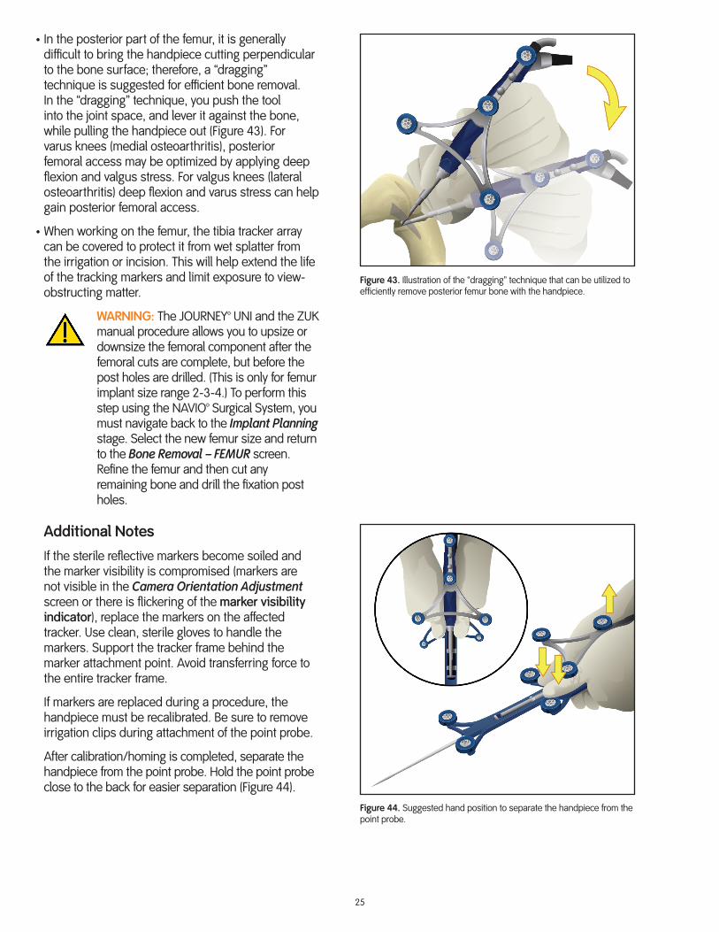
• In the posterior part of the femur, it is generally difficult to bring the handpiece cutting perpendicular to the bone surface; therefore, a “dragging” technique is suggested for efficient bone removal. In the “dragging” technique, you push the tool into the joint space, and lever it against the bone, while pulling the handpiece out (Figure 43). For varus knees (medial osteoarthritis), posterior femoral access may be optimized by applying deep flexion and valgus stress. For valgus knees (lateral osteoarthritis) deep flexion and varus stress can help gain posterior femoral access.
• When working on the femur, the tibia tracker array can be covered to protect it from wet splatter from the irrigation or incision. This will help extend the life of the tracking markers and limit exposure to view-obstructing matter.
WARNING: The JOURNEY™ UNI and the ZUK manual procedure allows you to upsize or downsize the femoral component after the femoral cuts are complete, but before the post holes are drilled. (This is only for femur implant size range 2-3-4.) To perform this step using the NAVIO™ Surgical System, you must navigate back to the Implant Planning stage. Select the new femur size and return to the Bone Removal – FEMUR screen. Refine the femur and then cut any remaining bone and drill the fixation post holes.
Additional Notes
If the sterile reflective markers become soiled and the marker visibility is compromised (markers are not visible in the Camera Orientation Adjustment screen or there is flickering of the marker visibility indicator), replace the markers on the affected tracker. Use clean, sterile gloves to handle the markers. Support the tracker frame behind the marker attachment point. Avoid transferring force to the entire tracker frame.
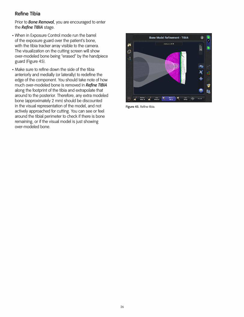
If markers are replaced during a procedure, the handpiece must be recalibrated. Be sure to remove irrigation clips during attachment of the point probe.
After calibration/homing is completed, separate the handpiece from the point probe. Hold the point probe close to the back for easier separation (Figure 44).
Figure 44. Suggested hand position to separate the handpiece from the point probe.
Figure 43. Illustration of the “dragging” technique that can be utilized to efficiently remove posterior femur bone with the handpiece.
26
Refine Tibia
Prior to Bone Removal, you are encouraged to enter the Refine TIBIA stage.
• When in Exposure Control mode run the barrel of the exposure guard over the patient’s bone, with the tibia tracker array visible to the camera. The visualization on the cutting screen will show over-modeled bone being “erased” by the handpiece guard (Figure 45).
• Make sure to refine down the side of the tibia anteriorly and medially (or laterally) to redefine the edge of the component. You should take note of how much over-modeled bone is removed in Refine TIBIA along the footprint of the tibia and extrapolate that around to the posterior. Therefore, any extra modeled bone (approximately 2 mm) should be discounted in the visual representation of the model, and not actively approached for cutting. You can see or feel around the tibial perimeter to check if there is bone remaining, or if the visual model is just showing over-modeled bone.
Figure 45. Refine tibia.

27
Cut Tibia
When burring bone near and around the collateral capsular structure (medial collateral ligament, MCL, or lateral collateral ligament, LCL) ensure that a retractor is used to prevent the bur from cutting the ligament (Figure 46). A Z knee retractor is included in the NAVIO™ instrument kit and provides a low-profile option, which minimizes obstruction of tracker arrays.
You should prepare the bone in the same anterior-to-posterior approach as is used on the femur. This approach creates space for the guard as the cutting moves into the posterior portion of the joint. It is strongly recommended that you remove the color down to the white target surface as cutting moves posterior (Figure 47).
• Make sure to uncover the tibia tracker array if it was covered for protection while burring the femur.
• Ensure that your assistant has various ligament protecting retractors readily available for use.
• Start at the anterior and bur with the handpiece held vertically to maximize exposure of the bur. Cut through the color indicated on the model down to white as the cutting moves posterior.
• Be sure to remove all of the green color up the side of the tibial eminence.
• Externally rotate the knee to aid in accessing a tight posterior tibial resection. Utilize a similar “dragging” technique, as is suggested for the posterior femur. To clean up remaining pieces of color on the floor of the tibia, start posterior and drag anterior.
• If the access becomes limited, switch to Speed Control mode. Use the icon in the upper-right corner of the touchscreen to switch control mode and finish the tibial cut.
Finish Cuts
If any cutting remains on the femur or tibia, simply press the Cut FEMUR or Cut TIBIA buttons to finalize the cuts. The system will prompt you to verify the checkpoints after 20 minutes of continual cutting and also upon a switch between femur and tibia bone removal. This ensures roughly one reverification of the checkpoints during cutting to ensure tracker arrays have not moved.
NOTE: If manual instrumentation (e.g. saws, rasps) is used for bone preparation at any time, make sure to switch to Refine FEMUR/TIBIA mode and update the affected bone model.
Figure 46. Use the Z knee retractor to spare the MCL (or LCL) from damage by the bur.
Figure 47. Start anterior and move posterior ensuring the color is removed to white as cutting moves posterior.
28
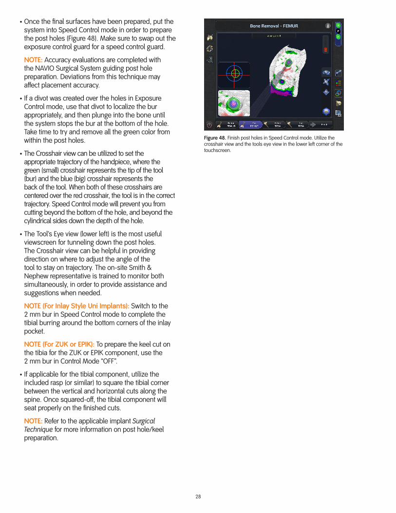
• Once the final surfaces have been prepared, put the system into Speed Control mode in order to prepare the post holes (Figure 48). Make sure to swap out the exposure control guard for a speed control guard.
NOTE: Accuracy evaluations are completed with the NAVIO Surgical System guiding post hole preparation. Deviations from this technique may affect placement accuracy.
• If a divot was created over the holes in Exposure Control mode, use that divot to localize the bur appropriately, and then plunge into the bone until the system stops the bur at the bottom of the hole. Take time to try and remove all the green color from within the post holes.
• The Crosshair view can be utilized to set the appropriate trajectory of the handpiece, where the green (small) crosshair represents the tip of the tool (bur) and the blue (big) crosshair represents the back of the tool. When both of these crosshairs are centered over the red crosshair, the tool is in the correct trajectory. Speed Control mode will prevent you from cutting beyond the bottom of the hole, and beyond the cylindrical sides down the depth of the hole.
• The Tool’s Eye view (lower left) is the most useful viewscreen for tunneling down the post holes. The Crosshair view can be helpful in providing direction on where to adjust the angle of the tool to stay on trajectory. The on-site Smith & Nephew representative is trained to monitor both simultaneously, in order to provide assistance and suggestions when needed.
NOTE (For Inlay Style Uni Implants): Switch to the 2 mm bur in Speed Control mode to complete the tibial burring around the bottom corners of the inlay pocket.
NOTE (For ZUK or EPIK): To prepare the keel cut on the tibia for the ZUK or EPIK component, use the 2 mm bur in Control Mode “OFF”.
• If applicable for the tibial component, utilize the included rasp (or similar) to square the tibial corner between the vertical and horizontal cuts along the spine. Once squared-off, the tibial component will seat properly on the finished cuts.
NOTE: Refer to the applicable implant Surgical Technique for more information on post hole/keel preparation.
Figure 48. Finish post holes in Speed Control mode. Utilize the crosshair view and the tools eye view in the lower left corner of the touchscreen.

29
Trial Reduction – UKRConfirm Sizing
• After completing all of the bone cuts and adjustments to the final surfaces, the incision should be cleaned and dried thoroughly. Because the bone has been burred away instead of sawed away, the debris tends to be of a finer quality, underscoring how important it is to properly clean the bony area in order to achieve good cement penetration, as well as to clear the joint space of free-floating bony debris.
• Once bone surface preparation is complete, perform a trial reduction (Figure 49) with the appropriate size femoral and tibial trial components, as described in the applicable implant Surgical Technique. If the joint is too tight, size the bearing component down to a thinner component, or resect more tibial bone.
WARNING: Some press fit may be necessary to ensure an optimal fit of the components, but be careful to avoid impinging or damaging cartilage at the transition area during impaction.
WARNING: Do not rock the trial components back and forth during removal, as this could compromise the bone preparation, post hole preparation, surrounding cartilage, and the implant’s fit.
Dynamic Test • The Collect Postop Baseline screen (Figure 50) will record normal flexion motion. Press and hold the right footpedal. Slowly move the leg through a normal (unstressed) range-of-motion to maximum flexion. Collect as many green bar sectors as possible.
• The Postop Stressed Gap Assessment screen (Figure 51) lets you assess the post-op gap throughout flexion in the medial or lateral compartments. The current line plot on the graph displays the planned stressed ROM from the Gap Planning stage. Apply constant varus and/or valgus stress to the collateral ligaments and collect the data throughout flexion. As you collect the data, the new line plot will be filled solid and display along with the previous line plot. You can collect these points either continuously or discretely.
• The trial tibial component must remain perfectly stable during ROM assessment.
• There should be no tilt effects in flexion; otherwise, the tibial slope must be readjusted.
• There should be no anteroposterior translation, as this indicates that the ligaments are too tight or the trial tibial bearing is too thick.
NOTE: If performing a UKR procedure, please proceed to the Cement and Close section in this guide.
Figure 49. Insert femoral and tibial trial components using the appropriate impactor set and select the appropriate bearing component if applicable.
Figure 50. Collect non-stressed range of motion.
Figure 51. Collect stressed range of motion.
30
Registration – PFACT-free Registration
The NAVIO™ Surgical System’s CT-free registration process for PFA utilizes standard image-free principles to construct a virtual representation of a patient’s anatomy and kinematics.
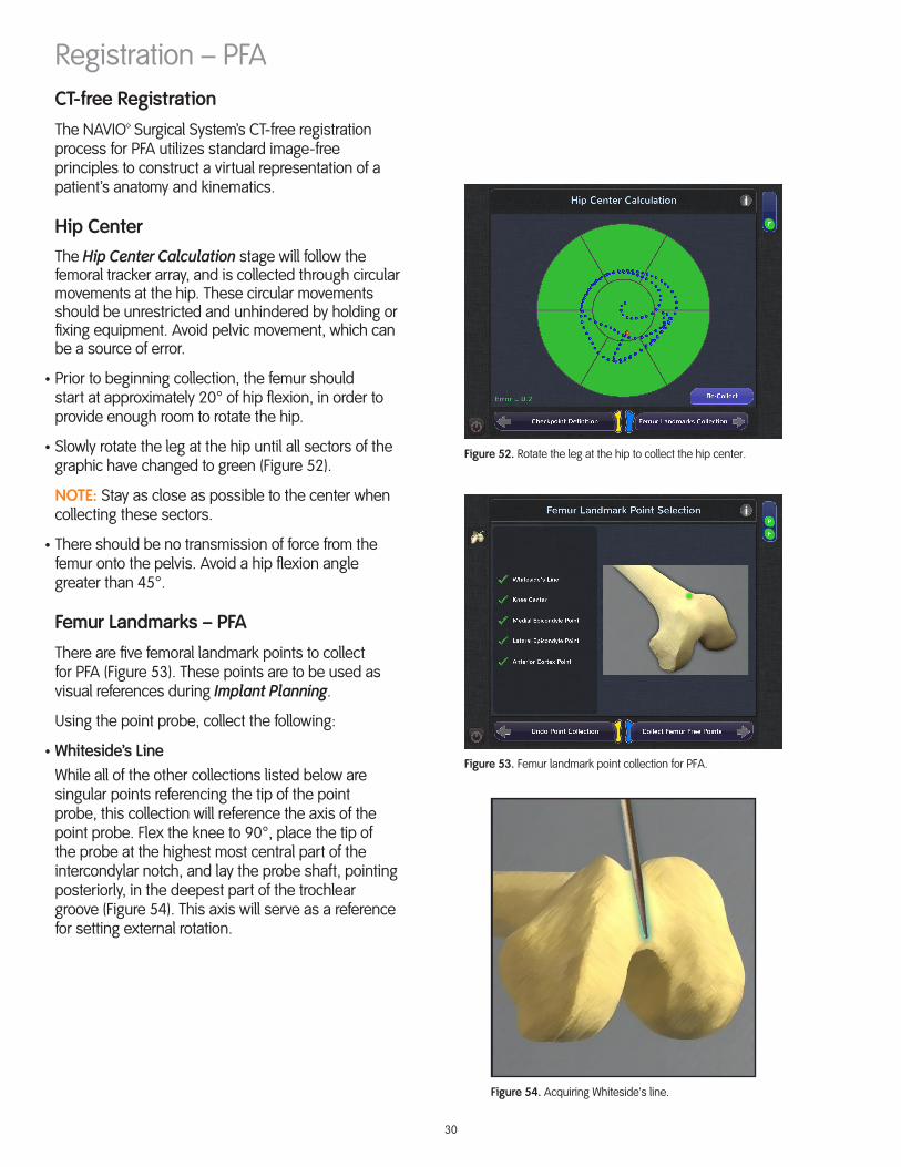
Hip CenterThe Hip Center Calculation stage will follow the femoral tracker array, and is collected through circular movements at the hip. These circular movements should be unrestricted and unhindered by holding or fixing equipment. Avoid pelvic movement, which can be a source of error.
• Prior to beginning collection, the femur should start at approximately 20° of hip flexion, in order to provide enough room to rotate the hip.
• Slowly rotate the leg at the hip until all sectors of the graphic have changed to green (Figure 52).
NOTE: Stay as close as possible to the center when collecting these sectors.
• There should be no transmission of force from the femur onto the pelvis. Avoid a hip flexion angle greater than 45°.
Femur Landmarks – PFA
There are five femoral landmark points to collect for PFA (Figure 53). These points are to be used as visual references during Implant Planning.
Using the point probe, collect the following:
• Whiteside’s LineWhile all of the other collections listed below are singular points referencing the tip of the point probe, this collection will reference the axis of the point probe. Flex the knee to 90°, place the tip of the probe at the highest most central part of the intercondylar notch, and lay the probe shaft, pointing posteriorly, in the deepest part of the trochlear groove (Figure 54). This axis will serve as a reference for setting external rotation.
Figure 52. Rotate the leg at the hip to collect the hip center.
Figure 53. Femur landmark point collection for PFA.
Figure 54. Acquiring Whiteside's line.
31
• Knee CenterCollect the center of the knee, which will be referenced as part of the femur weight bearing axis.
• Medial Epicondyle PointPlace the probe at the origin of the medial collateral ligament, which is found at the bottom of a sulcus in the medial epicondyle.
• Lateral Epicondyle PointPlace the probe on the most prominent point of the lateral epicondyle.NOTE: The epicondyle points collected are not used for any rotational references or critical calculations. They only serve to approximate the initial bone model size for the femur free collection stage.
• Anterior Cortex PointPlace the probe on the expected anterior termination of the femoral implant component.
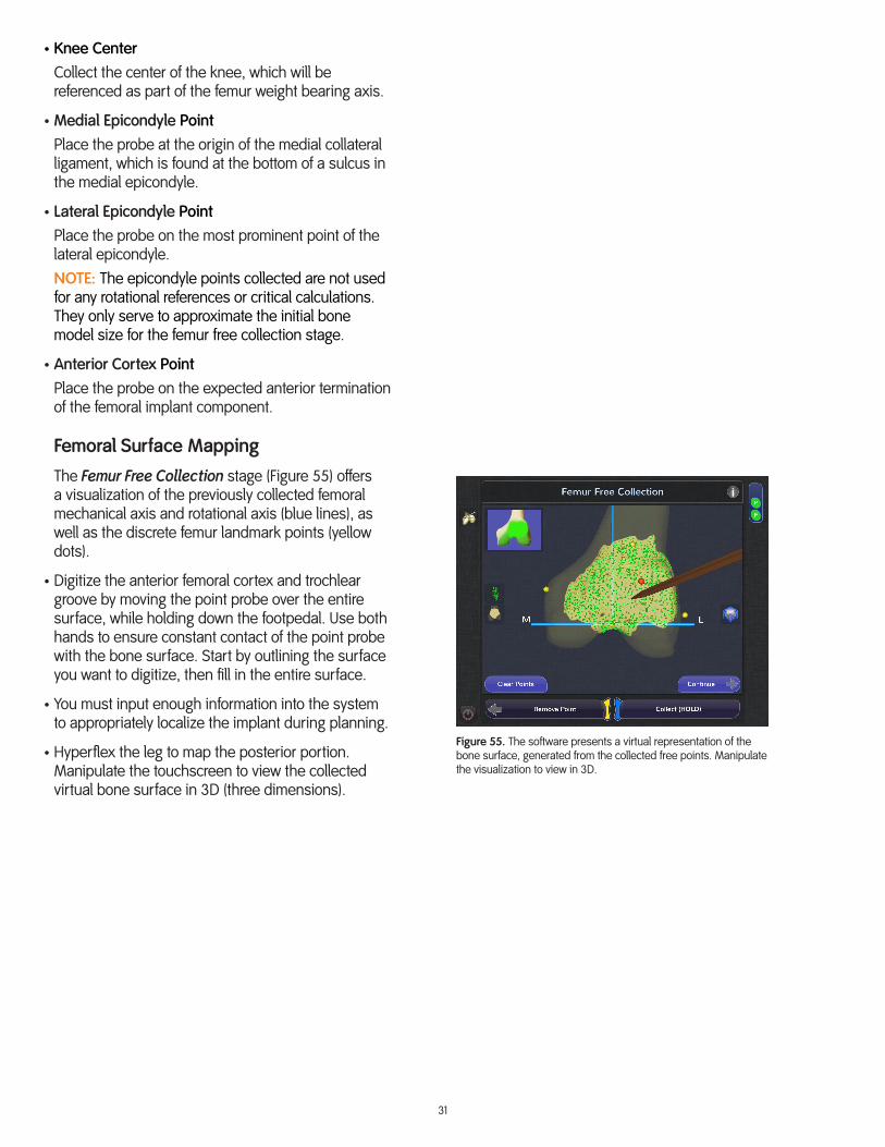
Femoral Surface Mapping
The Femur Free Collection stage (Figure 55) offers a visualization of the previously collected femoral mechanical axis and rotational axis (blue lines), as well as the discrete femur landmark points (yellow dots).
• Digitize the anterior femoral cortex and trochlear groove by moving the point probe over the entire surface, while holding down the footpedal. Use both hands to ensure constant contact of the point probe with the bone surface. Start by outlining the surface you want to digitize, then fill in the entire surface.
• You must input enough information into the system to appropriately localize the implant during planning.
• Hyperflex the leg to map the posterior portion. Manipulate the touchscreen to view the collected virtual bone surface in 3D (three dimensions).
Figure 55. The software presents a virtual representation of the bone surface, generated from the collected free points. Manipulate the visualization to view in 3D.
32
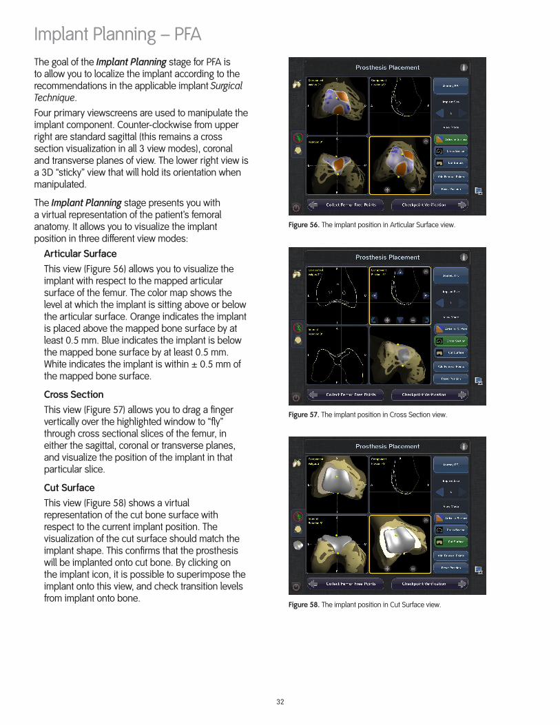
Implant Planning – PFAThe goal of the Implant Planning stage for PFA is to allow you to localize the implant according to the recommendations in the applicable implant Surgical Technique.Four primary viewscreens are used to manipulate the implant component. Counter-clockwise from upper right are standard sagittal (this remains a cross section visualization in all 3 view modes), coronal and transverse planes of view. The lower right view is a 3D “sticky” view that will hold its orientation when manipulated.
The Implant Planning stage presents you with a virtual representation of the patient’s femoral anatomy. It allows you to visualize the implant position in three different view modes:
Articular SurfaceThis view (Figure 56) allows you to visualize the implant with respect to the mapped articular surface of the femur. The color map shows the level at which the implant is sitting above or below the articular surface. Orange indicates the implant is placed above the mapped bone surface by at least 0.5 mm. Blue indicates the implant is below the mapped bone surface by at least 0.5 mm. White indicates the implant is within ± 0.5 mm of the mapped bone surface.
Cross SectionThis view (Figure 57) allows you to drag a finger vertically over the highlighted window to “fly” through cross sectional slices of the femur, in either the sagittal, coronal or transverse planes, and visualize the position of the implant in that particular slice.
Cut SurfaceThis view (Figure 58) shows a virtual representation of the cut bone surface with respect to the current implant position. The visualization of the cut surface should match the implant shape. This confirms that the prosthesis will be implanted onto cut bone. By clicking on the implant icon, it is possible to superimpose the implant onto this view, and check transition levels from implant onto bone.
Figure 56. The implant position in Articular Surface view.
Figure 57. The implant position in Cross Section view.
Figure 58. The implant position in Cut Surface view.

33
The NAVIO™ Surgical System software will provide an initial placement of the femoral component, utilizing the anterior cortex and knee center landmark points that were collected during the Registration section, and default to the smallest available implant size. From the initial placement, you have the ability to adjust the size and placement of the component.
NOTE (For SIGMA): Select the proper implant size of the SIGMA High Performance Partial Knee – PFJ so that the distal tip sits 2 to 3 mm above the apex of the intracondylar notch roof and the width does not exceed local anatomy. The superior border of the implant will lie just above the superior articular surface of the trochlea.
When localizing the component on the digitized surface, the following steps are key metrics to review and confirm:
• Confirm the rotation of the femoral component matches native anatomy, where possible.
• The distal triangle (distal tip) of the implant is suitably flush with the bone and the trochlea of the implant should reflect the anatomic trochlea.
• Confirm that the implant fixation post (top of intercondylar notch) is suitably below the bone surface (Figure 59). The trochlea of the implant should reflect the anatomic trochlea (i.e., the axis of Whiteside’s line).
• Confirm that the transitions between the distal/inferior implant walls and the femoral condyles are as level as possible (i.e., that there is no downward or upward transition step). This enables the patella to run smoothly over this part of the joint (Figure 60).NOTE: It is better to err towards having the implant slightly recessed, rather than protrude into the transition zone.
• Confirm that the anterior implant cut is tangential to the anterior cortex, in order to prevent notching or over-stuffing of the anterior joint.
The Reset Position function serves to approximate a “best fit” for the implant on the femur, subject to the collected bone references and determined transition areas. It uses the implant geometry along with the transition zone on the bone mesh from anterior cortex onto condyles and intercondylar notch, to position the implant, so that it falls within the guidelines listed above. It is important to note that if you press the Reset Position button after changing the component size, the NAVIO Surgical System will move the component back to a best fit estimate. Use the implant position functions in the touchscreen windows to fine-tune the implant placement.
Figure 59. The implant fixation post is suitably below the bone surface.
Figure 60. View of the critical transition between implant and bone on the distal femur.

34
Bone Cutting – PFABone Preparation
During bone preparation, you will execute the surgical plan as generated from the Implant Planning stage.
To make adjustments to the plan at any time during the cutting process, select the Back to Planning button. After making the adjustments, you may move forward again to the Bone Removal stage to continue bone preparation.
Setup
The following are tips for using the NAVIO™ Surgical System to prepare the bone:
• The handpiece and drill cables should rest on the operating room table within the sterile field. Take care not to drop them below the table. Resting the cables on the table running below the trackers and up to the handpiece by the patient’s foot will help keep the cables from waving in front of the bone tracker arrays. During cutting, if the camera loses sight of either of the bone tracker arrays, check that the cables have not obscured any of the tracking markers.
• The irrigation needs to prime for approximately 20 seconds prior to active irrigation (Figure 61). To prime the fluid, put the system into Cut FEMUR and depress the black Anspach® footpedal. This will run the peristaltic pump on the side of the NAVIO™ system cart.
• Remove any remaining osteophytes that may be visible. Remove the anterior horn of the meniscus.
• A self-retaining retractor, like the Gelpie retractor, has proven useful at keeping the incision open and bone exposed during cutting. This allows your assistant to focus on other retractions or tasks.
Figure 61. Irrigation is set up on the side of the NAVIO system cart to flow when the drill footpedal is depressed.
35
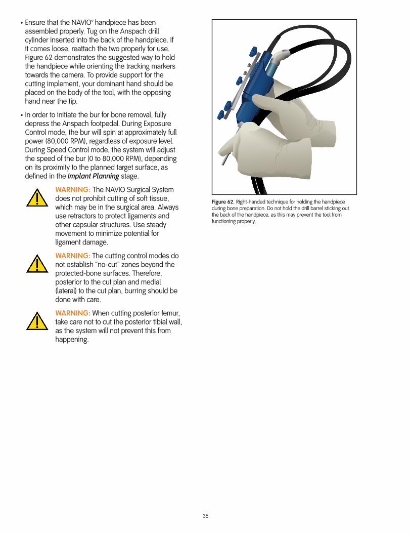
• Ensure that the NAVIO™ handpiece has been assembled properly. Tug on the Anspach drill cylinder inserted into the back of the handpiece. If it comes loose, reattach the two properly for use. Figure 62 demonstrates the suggested way to hold the handpiece while orienting the tracking markers towards the camera. To provide support for the cutting implement, your dominant hand should be placed on the body of the tool, with the opposing hand near the tip.
• In order to initiate the bur for bone removal, fully depress the Anspach footpedal. During Exposure Control mode, the bur will spin at approximately full power (80,000 RPM), regardless of exposure level. During Speed Control mode, the system will adjust the speed of the bur (0 to 80,000 RPM), depending on its proximity to the planned target surface, as defined in the Implant Planning stage.
WARNING: The NAVIO Surgical System does not prohibit cutting of soft tissue, which may be in the surgical area. Always use retractors to protect ligaments and other capsular structures. Use steady movement to minimize potential for ligament damage.
WARNING: The cutting control modes do not establish “no-cut” zones beyond the protected-bone surfaces. Therefore, posterior to the cut plan and medial (lateral) to the cut plan, burring should be done with care.
WARNING: When cutting posterior femur, take care not to cut the posterior tibial wall, as the system will not prevent this from happening.
Figure 62. Right-handed technique for holding the handpiece during bone preparation. Do not hold the drill barrel sticking out the back of the handpiece, as this may prevent the tool from functioning properly.

36
Screen Overview
Figure 63 shows a typical Bone Removal screen for PFA with the following icons/buttons identified:
1 – Checkpoint Verification button is used to manually force a verification of the defined checkpoint positions on the femur and tibia.
2 – Change Bur button is used to update the system about a change you made to the selected bur size.
3 – Back to Planning button returns you to the Gap Planning screen to make adjustments to the prosthesis placement plan.
4 – Tool’s Eye View displays “what the tool sees,” similar to a scope view, and it is continuously active.
5 – Isometric Cut Model can be manipulated based on user view preference.
6 – Control Mode Indicator displays which control mode (exposure or speed) you are currently using. Pressing the button will allow you to change the selected control mode.
7 – Tracker Array Status will show if a tracker array is visible to the camera (green) or obstructed (black). Check this status indicator if the system is not cutting, as it will prevent bone cutting when an array important to the action is obstructed from view. You may also press this icon to present a Field of View screen to confirm tracker array visibility within the camera’s field of view.
8 – Tool’s Eye View button is used to toggle between bird’s-eye view (default view) and tool’s eye view.
9 – Color Depth Legend button may be toggled on or off. Activate the legend to view colors corresponding to depth (mm) to target surface.
10 – Crosshair View button may be toggled on or off. Activate this view when preparing fixation features, like post-holes.
11 – Virtual Trial Implant button may be used to activate a virtual implant that will be shown on the main viewscreen. This is useful to confirm progress to the cut plan, and to check for overhang of implant on bone.
12 – Screenshot button can be used at any time to capture a screenshot of whatever is currently on the monitor. The screenshot will be saved for access when archiving the patient.
13 – Cutting Mode (Refine FEMUR, Cut FEMUR) highlights the current mode that you are using, and can be used to navigate to other modes.
Figure 63. Typical Bone Removal screen.
2
10
3
11
1
12
7
4
5 6
13
98
37
Refine Femur
Prior to Bone Removal, you are encouraged to enter the Refine FEMUR mode.
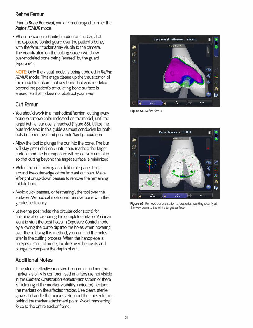
• When in Exposure Control mode, run the barrel of the exposure control guard over the patient’s bone, with the femur tracker array visible to the camera. The visualization on the cutting screen will show over-modeled bone being “erased” by the guard (Figure 64).
NOTE: Only the visual model is being updated in Refine FEMUR mode. This stage cleans up the visualization of the model to ensure that any bone that was modeled beyond the patient’s articulating bone surface is erased, so that it does not obstruct your view.
Cut Femur
• You should work in a methodical fashion, cutting away bone to remove color indicated on the model, until the target (white) surface is reached (Figure 65). Utilize the burs indicated in this guide as most conducive for both bulk bone removal and post hole/keel preparation.
• Allow the tool to plunge the bur into the bone. The bur will stay protruded only until it has reached the target surface and the bur exposure will be actively adjusted so that cutting beyond the target surface is minimized.
• Widen the cut, moving at a deliberate pace. Trace around the outer edge of the implant cut plan. Make left-right or up-down passes to remove the remaining middle bone.
• Avoid quick passes, or“feathering”, the tool over the surface. Methodical motion will remove bone with the greatest efficiency.
• Leave the post holes (the circular color spots) for finishing after preparing the complete surface. You may want to start the post holes in Exposure Control mode by allowing the bur to dip into the holes when hovering over them. Using this method, you can find the holes later in the cutting process. When the handpiece is on Speed Control mode, localize over the divots and plunge to complete the depth of cut.
Additional Notes
If the sterile reflective markers become soiled and the marker visibility is compromised (markers are not visible in the Camera Orientation Adjustment screen or there is flickering of the marker visibility indicator), replace the markers on the affected tracker. Use clean, sterile gloves to handle the markers. Support the tracker frame behind the marker attachment point. Avoid transferring force to the entire tracker frame.
Figure 65. Remove bone anterior-to-posterior, working cleanly all the way down to the white target surface.
Figure 64. Refine femur.
38
If markers are replaced during a procedure, the handpiece must be recalibrated. Be sure to remove irrigation clips during attachment of the point probe.
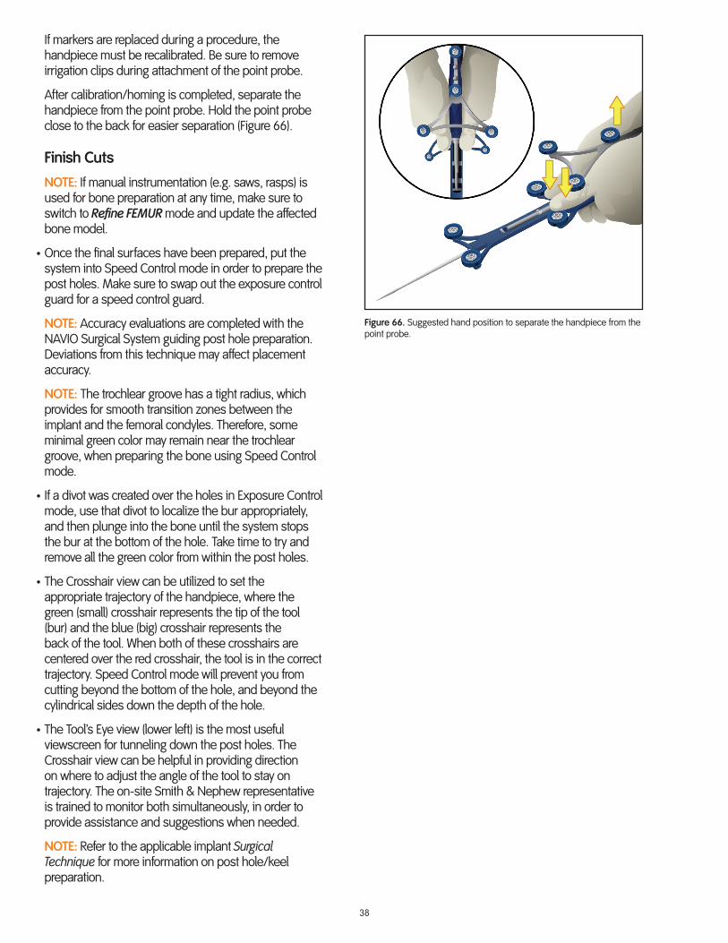
After calibration/homing is completed, separate the handpiece from the point probe. Hold the point probe close to the back for easier separation (Figure 66).
Finish Cuts
NOTE: If manual instrumentation (e.g. saws, rasps) is used for bone preparation at any time, make sure to switch to Refine FEMUR mode and update the affected bone model.
• Once the final surfaces have been prepared, put the system into Speed Control mode in order to prepare the post holes. Make sure to swap out the exposure control guard for a speed control guard.
NOTE: Accuracy evaluations are completed with the NAVIO Surgical System guiding post hole preparation. Deviations from this technique may affect placement accuracy.
NOTE: The trochlear groove has a tight radius, which provides for smooth transition zones between the implant and the femoral condyles. Therefore, some minimal green color may remain near the trochlear groove, when preparing the bone using Speed Control mode.
• If a divot was created over the holes in Exposure Control mode, use that divot to localize the bur appropriately, and then plunge into the bone until the system stops the bur at the bottom of the hole. Take time to try and remove all the green color from within the post holes.
• The Crosshair view can be utilized to set the appropriate trajectory of the handpiece, where the green (small) crosshair represents the tip of the tool (bur) and the blue (big) crosshair represents the back of the tool. When both of these crosshairs are centered over the red crosshair, the tool is in the correct trajectory. Speed Control mode will prevent you from cutting beyond the bottom of the hole, and beyond the cylindrical sides down the depth of the hole.
• The Tool’s Eye view (lower left) is the most useful viewscreen for tunneling down the post holes. The Crosshair view can be helpful in providing direction on where to adjust the angle of the tool to stay on trajectory. The on-site Smith & Nephew representative is trained to monitor both simultaneously, in order to provide assistance and suggestions when needed.
NOTE: Refer to the applicable implant Surgical Technique for more information on post hole/keel preparation.
Figure 66. Suggested hand position to separate the handpiece from the point probe.

39
Trial Reduction – PFAConfirm Sizing
• After completing all of the bone cuts and adjustments to the final surfaces, the incision should be cleaned and dried thoroughly. Because the bone has been burred away instead of sawed away, the debris tends to be of a finer quality, underscoring how important it is to properly clean the bony area in order to achieve good cement penetration, as well as to clear the joint space of free-floating bony debris.
• Once bone surface preparation is complete, perform a trial reduction (Figure 67) with the appropriate size trial component, as described in the applicable implant Surgical Technique.
WARNING: Some press fit may be necessary to ensure an optimal fit of the components, but be careful to avoid impinging or damaging cartilage at the transition area during impaction.
• Evaluate patellofemoral tracking throughout a range of motion.
WARNING: Do not rock the trial components back and forth during removal, as this could compromise the bone preparation, post hole preparation, surrounding cartilage, and the implant’s fit.
Cement and CloseRemove Checkpoint Verification Pins
WARNING: Prior to closing the patient’s incision, be sure to remove both the femoral and tibial (if applicable) bone checkpoint verification pins.
Final Components
• Finish the implantation of the final components, as recommended in the applicable implant Surgical Technique, using appropriate instruments and tools.
Figure 67. Insert trial component using the appropriate impactor set.
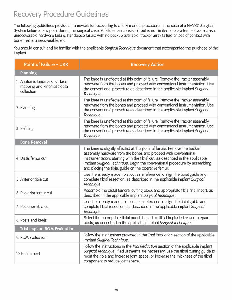
40
Recovery Procedure GuidelinesThe following guidelines provide a framework for recovering to a fully manual procedure in the case of a NAVIO™ Surgical System failure at any point during the surgical case. A failure can consist of, but is not limited to, a system software crash, unrecoverable hardware failure, handpiece failure with no backup available, tracker array failure or loss of contact with bone that is unrecoverable, etc.
You should consult and be familiar with the applicable Surgical Technique document that accompanied the purchase of the implant.
Point of Failure – UKR Recovery Action
Planning
1. Anatomic landmark, surface mapping and kinematic data collection
The knee is unaffected at this point of failure. Remove the tracker assembly hardware from the bones and proceed with conventional instrumentation. Use the conventional procedure as described in the applicable implant Surgical Technique.
2. Planning
The knee is unaffected at this point of failure. Remove the tracker assembly hardware from the bones and proceed with conventional instrumentation. Use the conventional procedure as described in the applicable implant Surgical Technique.
3. Refining
The knee is unaffected at this point of failure. Remove the tracker assembly hardware from the bones and proceed with conventional instrumentation. Use the conventional procedure as described in the applicable implant Surgical Technique.
Bone Removal
4. Distal femur cut
The knee is slightly affected at this point of failure. Remove the tracker assembly hardware from the bones and proceed with conventional instrumentation, starting with the tibial cut, as described in the applicable implant Surgical Technique. Begin the conventional procedure by assembling and placing the tibial guide on the operative femur.
5. Anterior tibia cutUse the already made tibial cut as a reference to align the tibial guide and complete tibial resection, as described in the applicable implant Surgical Technique.
6. Posterior femur cut Assemble the distal femoral cutting block and appropriate tibial trial insert, as described in the applicable implant Surgical Technique.
7. Posterior tibia cutUse the already made tibial cut as a reference to align the tibial guide and complete tibial resection, as described in the applicable implant Surgical Technique.
8. Posts and keels Select the appropriate tibial punch based on tibial implant size and prepare posts, as described in the applicable implant Surgical Technique.
Trial Implant ROM Evaluation
9. ROM Evaluation Follow the instructions provided in the Trial Reduction section of the applicable implant Surgical Technique.
10. Refinement
Follow the instructions in the Trial Reduction section of the applicable implant Surgical Technique. If adjustments are necessary, use the tibial cutting guide to recut the tibia and increase joint space, or increase the thickness of the tibial component to reduce joint space.
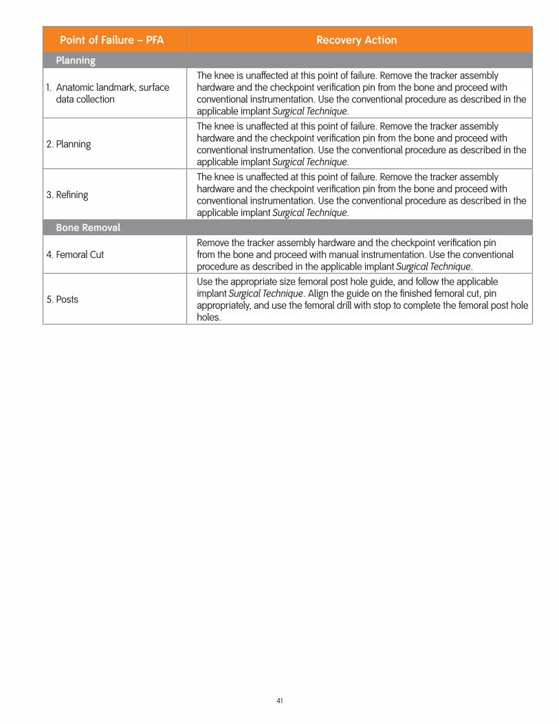
41
Point of Failure – PFA Recovery Action
Planning
1. Anatomic landmark, surface data collection
The knee is unaffected at this point of failure. Remove the tracker assembly hardware and the checkpoint verification pin from the bone and proceed with conventional instrumentation. Use the conventional procedure as described in the applicable implant Surgical Technique.
2. Planning
The knee is unaffected at this point of failure. Remove the tracker assembly hardware and the checkpoint verification pin from the bone and proceed with conventional instrumentation. Use the conventional procedure as described in the applicable implant Surgical Technique.
3. Refining
The knee is unaffected at this point of failure. Remove the tracker assembly hardware and the checkpoint verification pin from the bone and proceed with conventional instrumentation. Use the conventional procedure as described in the applicable implant Surgical Technique.
Bone Removal
4. Femoral CutRemove the tracker assembly hardware and the checkpoint verification pin from the bone and proceed with manual instrumentation. Use the conventional procedure as described in the applicable implant Surgical Technique.
5. Posts
Use the appropriate size femoral post hole guide, and follow the applicable implant Surgical Technique. Align the guide on the finished femoral cut, pin appropriately, and use the femoral drill with stop to complete the femoral post hole holes.

Manufacturer:
Blue Belt Technologies, Inc. www.smith-nephew.com2905 Northwest Blvd., Suite 40Plymouth, MN 55441 USA
Customer Support:
tel: 763-452-4910fax: 763-452-4980email: [email protected]
Smith & Nephew Orthopaedics GmbHAlemannenstrasse 14, 78532Tuttlingen, Germany
™ Trademark of Smith & Nephew. All Trademarks acknowledged.
This product may be covered by one or more US Patents.See www.smith-nephew.com/patents for details.
14528 V1 500098 REVD 09/18
0123
© Smith & Nephew 2018
Issue Date: 09-2018


