NCHRP Project 12-38 RECOMMENDED SPECIFICATIONS FOR STEEL CURVED-GIRDER BRIDGES Prepared for National Cooperative Highway Research Program Transportation Research Board National Research Council TRANSPORTATION RESEARCH BOARD NAS-NRC PRIVILEGED DOCUMENT This report, not released for publication, is furnished only for review to members of or participants in the work of the National Cooperative Highway Research Program. It is to be regarded as fully privileged, and dissemination of the information included herein must be approved by the NCHRP. Dann H. Hall Bridge Software Development International, Ltd. Coopersburg, Pennsylvania and Chai H. Yoo Highway Research Center Auburn University Auburn University, Alabama July 1998 COPY No. 24
Transcript
NCHRP Project 12-38
RECOMMENDED SPECIFICATIONS
FOR STEEL CURVED-GIRDER BRIDGES
Prepared for National Cooperative Highway Research Program
Transportation Research Board National Research Council
TRANSPORTATION RESEARCH BOARD
NAS-NRC PRIVILEGED DOCUMENT
This report, not released for publication, is furnished only for review to members of or participants in the work of the National Cooperative Highway Research Program. It is to be regarded as fully privileged, and dissemination of the information included herein must be approved by the NCHRP.
Dann H. Hall Bridge Software Development International, Ltd.
Coopersburg, Pennsylvania
and
Chai H. Yoo Highway Research Center
Auburn University Auburn University, Alabama
July 1998
COPY No. 24
Recommended Specifications Printed on July 10, 1998
Acknowledgment
This work was sponsored by the American Association of State Highway and Transportation Officials, in cooperation with the Federal Highway Administration, and was conducted in the National Cooperative Highway Research Program which is administered by the Transportation Research Board of the National Research Council.
Disclaimer
This copy is an uncorrected draft as submitted by the research agencies. A decision concerning acceptance by the Transportation Research Board and publication in the regular NCHRP series will not be made until a complete technical review has been made and discussed with the researchers. The opinions and conclusions expressed or implied in the report are those of the research agencies. They are not necessarily those of the Transportation Research Board, the National Research Council, or the Federal Highway Administration, American Association of State Highway and Transportation Officials, or of the individual states participating in the National Cooperative Highway Research Program.
Aubum University I Hall iii
Recommended Specifications Printed on July 10, 1998
PREFACE
AASHTO first published Guide Specifications for Horizontally Curved Highway Bridges in 1980. These guide specifications included Allowable Stress Design (ASD) provisions developed by the Consortium of University Research Teams (CURT) and approved by ballot of the AASHTO Highway Subcommittee on Bridges and Structures in November 1976. CURT consisted of Carnegie-Mellon University, the University of Pennsylvania, the University of Rhode island and Syracuse University. The 1980 guide specifications also included Load Factor Design (L r.D) provisions developed in American Iron and Steel Institute (AISI) Project 190 and approved by ballot of the AASHTO Highway Subcommittee on Bridges and Structures in October 1979. The guide specifications covered both I and box girders.
Changes to the 1980 guide specifications were included in the AASHTO Interim Specifications - Bridges for the years 1981, 1982, 1984, 1985, 1986, and 1990. A new version of the Guide Specifications for Horizontally Curved Highway Bridges was published in 1993. It included these interim changes, and additional changes, but did not reflect the extensive research on curved-girder bridges that has been conducted since 1980 or many important changes in related provisions of the straight-girder specifications.
The present draft specifications and commentary were developed to correct these deficiencies. They reflect the current state-of-the-art and are consistent with present straight-girder specifications except as noted. They were developed in National Cooperative Highway Research Program (NCHRP) Project 12-38 and are fully documented in NCHRP Interim Reports, I GIRDER CURVATURE STUDY and CURVED GIRDER DESIGN AND CONSTRUCTION, CURRENT PRACTICE.
The following terms are used to identify particular specifications:
-ANSI/AASHTO/AWS refers to the 1996 edition of 01.5-96 Bridge Welding Code, American Welding Society,
- "previous curved-girder specifications" or Guide Spec refer to the 1993 AASHTO Guide Specifications for Horizontally Curved Highway Bridges,
- LFDI ASD refers to the 1996 AASHTO Standard Specifications for Highway Bridges, 16th edition and Interim Specifications - 1997 and
-LRFD refers to the 1996 AASHTO LRFD Bridge Design Specifications.
It is expected that curved-girder draft specifications based on the present AASHTO LFD specifications will be incorporated into the AASHTO Load and Resistance Factor Design (LRFD) specifications in the future. An extensive theoretical and experimental research program is being conducted on curved-girder bridges under sponsorship of the Federal Highway Administration (FHWA). This program should permit further improvements in the proposed curved-girder specifications.
Aubum University I Hall iv
Recommended Specifications Printed on July 10, 1998
TABLE OF CONTENTS DIVISION I - DESIGN
PREFACE ................................................................ iv
Definition . ............................................................... xi
4.5.1 General .................................................. 26 4.5.2 Stresses in Composite Sections ......................... ...... 26 4.5.3 Prestressed Concrete ................................. ...... 27
4.6 Construction Stages ......... ................ ................ ...... 28
5 Flanges with One Web .................................................... 29 5.1 General ......................................................... 29 5.2 Partially Braced Compression Flanges ................................. 30
Index . ................... . ............................................ 101
Auburn University I Hall ix
Recommended Specifications Printed on July 10, 1998
Definition
For a consistent application of the specifications, it is necessary that terms be defined where they have particular meanings in the specifications. The definition given in the following are for use in application of these specifications only and do not always correspond to ordinary usage:
Abutment: An end support for a bridge superstructure, which usually resists horizontal forces as well as vertical reactions. An abutment is usually flanked by wing walls.
Action: A generalized force in a structural member or component including moment, shear, axial force and externally applied load. Deflections and rotations are also considered as actions.
Arc Span: Distance between centers of adjacent bearings, or other points of support, measured horizontally along the centerline of a horizontally curved member.
Aspect Ratio: Ratio computed by dividing the length by the width of a rectangular panel.
Beam: A structural member whose primary function is to transmit loads to the supports through flexure.
Box Flange: A flange that is connected to two webs. The flange may be a flat unstiffened plate, a stiffened plate or a flat plate with reinforced concrete attached to the plate with shear connectors.
Bracing Member: A member intended to brace a girder against lateral movement or distortion.
Closed Box Girder: A bending member having a cross section composed of two webs which has at least a completely enclosed cell. A closed section girder is effective in resisting applied torsion by developing non-vanishing shear flow in the web(s) and flanges.
Compact Flange: A partially or fully braced flange that can sustain sufficient strains so that the entire flange can be assumed to be at the yield stress.
Component: A constituent part of a structure.
Composite Girder: A steel I-shaped or box-shaped bending member connected to a concrete slab so that the steel element and the slab, or the longitudinal reinforcement within the slab, respond to bending loads as a unit.
Connection: A weld, or arrangement of bolts, that transfers normal and/or shear stresses from one element to another.
Contractor: An organization that agrees to build the bridge for the Owner according to the terms of a ,contract executed by the Owner and the Contractor.
Cracked Section: A composite section in which the concrete is assumed to carry no stress.
Auburn University / Hall xi
Recommended Specifications Printed on July 10, 1998
Cross Section Distortion: Distortion of the cross section of a box or tub girder due to torsional loading.
Curved Girder: An I, closed box or tub girder that is curved in a horizontal plane.
Deck: The roadway composed of concrete and reinforcement.
Design: Proportioning and detailing the components and connections of a bridge to satisfy these specifications.
Diaphragm: A vertically oriented solid transverse member connecting adjacent longitudinal girders or inside a closed box or tub girder.
Distortion-Induced Fatigue: Fatigue caused by secondary stresses that are not normally evaluated in the typical design and analysis of a bridge.
Engineer: A licensed structural engineer responsible for design of the bridge or review of the bridge construction.
Factored Loading: The nominal loads multiplied by the appropriate load factors specified for the load group under consideration.
Fatigue: The initiation/or propagation of cracks in steel members due to repeated variation of strain.
Fatigue Resistance: The maximum stress range that can be sustained for a specified number of cycles without failure.
Finite Element Method: A method of analysis in which the structure is divided into elements connected at nodes. The shape of the element displacement field is assumed, partial or complete compatibility is maintained among the element interfaces, and nodal displacements are determined by using energy prinCiples or equilibrium methods.
First-Order Analysis: An analysis based on small-deflection theory under linearly elastic constitutive equations.
Flange Concrete: Reinforced concrete acting with a box flange design to resist vertical bending and torsion.
Girder Radius: The radius of the circumferential centerline of a segment of a curved girder.
Grid Method: A method of analysis in which all or part of the superstructure is discretized ini components in a two-dimensional plane that represent the characteristics of the structure.
Auburn University / Hall xii
Recommended Specifications Printed on July 10,1998
Hooke's Law: Stress in a material is proportional to strain.
Inelastic Behavior: A condition in which deformation is not fully recovered upon removal of the load. Strain exceeds the proportional limit.
I Girder: A bending member that has an I-shaped cross section.
Lane: The area of deck receiving one vehicle or one uniform load line.
Lateral Bending Stress: Bending stress caused by lateral flange bending.
Lateral Bracing: A truss placed in a horizontal plane between two I girders or two flanges of a tub girder.
Lateral Flange Bending: Flexural action of a flange in the plane of the flange with respect to the vertical axis through the flange. Lateral flange bending may be due to lateral loads applied to the flange and/or nonuniform torsion in the member. In these provisions lateral flange bending moments refer to those at brace points.
Load Effect: Moment, shear, axial force, or torque induced in a member by loads applied to the structure.
Load and Resistance Factor Design (LRFD): A reliability-based design method in which factored design forces caused by factored service loads are not permitted to exceed the nominal strengths of the members.
Main Member: A primary member designed to carry the internal forces determined from an analysis.
Model: A mathematical idealization of a structure or component used for analysis.
MIR Method: An approximate method for the analysis of curved box girders in which the curved girder is treated as an equivalent straight girder to calculate bending effects and as a corresponding straight conjugate beam to calculate the concomitant St. Venant torsional moments due to curvature.
Muller-Breslau Principle: The influence surface for an action at a preselected point of a linear elastic structure is to the same scale as the deflected shape of the structure when the structure is given a unit deformation at the preselected point corresponding to the action.
Navier's Hypothesis: In any bent beam, sections which were plane before bending remain plane after bending. Also known as the Bernoulli-Euler assumption.
Negative Moment: Moment producing tension at the top of a bending element.
Auburn University / Hall xiii
Recommended Specifications Printed on July 10, 1998
Non-compact Flange: A compression flange that can sustain a peak normal strain at the flange tip equal to the yield strain.
Nonuniform Torsion: An internal resisting torsion in thin-walled sections producing shear stresses and normal stresses, and under which cross sections do not remain plane. Nonuniform torsion is also known as warping torsion. Members developing nonuniform torsion resist the externally applied torsion by warping torsion and St. Venant torsion. Each of these components of internal resisting torsion varies along the member length although the externally applied concentrated torsion may remain uniform along the member between two adjacent points of torsional restraint. Warping torsion is dominant over St. Venant torsion in members having open cross sections whereas St. Venant torsion is dominant over warping torsion in members having closed cross sections.
Open Section: A bending member cross section which has no enclosed cell. An open section member resists torsion primarily by nonuniform torsion, which causes normal stresses at the flange tips.
Owner: A person or an organization who pays for the construction of the structure and assumes the responsibility of its operation and maintenance.
Pier: A column or connected group of columns or other configuration designed to be an interior support for a bridge superstructure.
Pitch: The distance between adjacent bolts or shear connectors in the direction of the force.
Positive Moment: Moment producing tension at the bottom of a bending element.
Second-Order Analysis: An analysis that accounts for geometric and/or material nonlinearity.
Secondary Member: A member in which stress is not normally evaluated in the analysis.
Shear Flow: Shear force acting on the cross section of a plate element divided by the thickness or width of the element; shear flow has the units of force per unit width of the plate.
Shear Lag: Nonlinear distribution of normal stress across an element due to shear distortions.
Shear Strength: Shear capacity of a component as computed using these provisions.
Smail-Deflection Theory: Any method of structural analysis in which the influence of deformation on force effects is neglected.
Slab: Deck composed of concrete and reinforcement.
Span Length: See Arc Span.
Auburn University / Hall xiv
Recommended Specifications Printed on July 10, 1998
Splice: A group of bolted connections, or a welded connection, sufficient to transfer the moment, shear, axial force, or torque between two girder components.
St. Venant Torsion: Internal resisting torsion producing pure shear stresses on a cross section. Torsion in members such as pipes or solid round bars where only st. Venant torsion resist the externally applied torsion is referred to either as pure torsion or uniform torsion.
Stress Range: The algebraic difference between the extreme values in a stress cycle in a fatigue check.
Stringer: A longitudinal bending member of open section such as an I girder. This term is frequently used interchangeably with I girder.
Strong-Axis: The centroidal axis about which the moment of inertia is a maximum.
Superposition: The stresses of a member due to one system of loading can be added to the stresses in it due to another system of loading if the load-stress relationship is linearly elastic and the sum is still within the elastic range.
Through-Thickness Stress: Bending stresses in the web or box flange induced by distortion of the cross section.
Torsional Shear Stress: Shear stress induced by St. Venant torsion.
Tub Girder: An open-topped steel girder which is composed of a bottom flange plate, two web plates and an independent top flange attached to the top of each web. The top flanges are connected with lateral bracing members.
Unbraced Length: The arc distance between brace points resisting the mode of buckling, lateral bending or distortion under consideration.
Uncracked Section: A composite section in which the concrete is assumed to be fully effective in tension.
Uniform Live Load: Loading consisting of a uniform load intensity and specified concentrated loads placed in critical positions longitudinally and transversely. These loads are referred to in AASHTO as lane loads.
Vertical Bending Moment: Bending moment about the horizontal axis, usually the strong-axis.
V-Load Method: An approximate method for the analysis of curved I girder bridges in which the curved girders are represented by equivalent straight girders and the effects of curvature are represented by vertical and lateral forces applied at cross frame locations. Lateral flange bending at brace points due to curvature is estimated.
Aubum University I Hall xv
Recommended Specifications Printed on July 10,1998
Von Mises Yield Criterion: A theory which states that inelastic action begins at a pOint subjected to biaxial or triaxial stresses when the strain energy of distortion per unit volume absorbed at that point is equal to the strain energy of distortion per unit volume absorbed at any point on a bar loaded to its yield strength under uniaxial tensile stress. This theory is also called the maximum strain-energy-of-distortion theory.
Warping Normal Stress: Normal stress induced by nonuniform torsion is referred to as warping stress.
Web Slenderness: The distance along a web between flanges divided by the web thickness.
Wheel Load Distribution Factor: The fraction of half of a truck or lane load assumed to be carried by an individual girder.
Yield Stress: The specified minimum yield stress for the steel.
Aubum University / Hall xvi
Recommended Specifications Printed on July 10, 1998
NOTATION
a = A bot = AO = As = b = bd = b, = bs = bs = C -' . C = D = D =
Dc = d = do = ds = E = F = Fbs =
FeR = Fcr =
Fcrt =
FCf2 =
F,at =
Fp =
Fr =
Fv = Fy =
fb = f' = c f, = fm = fv =
aspect ratio of transverse stiffeners (6.5) (6.6) area of bottom flange (in2) (7.2.2) enclosed area of box (in2) (C10.4.2.2) area of steel girder (in2) (7.2.1) minimum flange width (in) (Division II, 3) effective deck width (in) (4.5.2) (7.2.1) flange width (in) (5.1) (5.2.1) (5.2.2) (C9.3.2) (10.4.2.4.1) (10.4.2.4.2) (10.4.3.5) stiffener width (in) (6.5) (6.6) distance between longitudinal stiffeners (in) (10.4.2.4.2) -ratio of the elastic shear-buckling strength to the shear-yield strength (6.2.2) equivalent moment factor (6.7) dead load (3.5.1) (3.5.4) distance along the web between flanges (in) (C4.2.1) (6.2) (6.2.1) (6.2.2) (6.3) (6.3.1) (6.3.2) (6.4) (6.4.1) (6.5) (6.6) depth of web in compression (in) (C6.1) (6.2.1) (6.3.1) required distance between transverse stiffeners (in) (6.3.2) (6.4) (6.5) actual distance between transverse stiffeners (in) (6.3) (6.3.2) (6.5) distance between longitudinal stiffener and compression flange (in) (6.4.1) Young's modulus of steel (ksi) (5.2.1) (5.2.2) (6.2.1) (6.2.2) (6.3.1) (6.4.1) (6.5) uniform radial force (klft) (C13.8) critical average normal stress in the compression flange of straight girder (ksi) (5.2.1 ) net range of cross frame axial force at the top flange (kip) (7.2.2) critical vertical bending stress (ksi) (5.1) (5.2.1) (5.2.2) (5.4) (6.2.1) (6.3.1) (6.4.1) (10.4.2.3) (10.4.2.4.1) (10.5) critical vertical bending stress calculated from reduction factors (ksi) (5.2.1) (5.2.2) (5.3) critical vertical bending stress determined from partial yielding (ksi) (5.2.1) (5.2.2) (5.3) radial fatigue shear range/unit length (klin) (7.2.2) (7.3.3) (10.5.2)
radial force in the concrete slab at point of maximum positive live load moment (kip)
(7.2.1 )
radial force in the concrete slab at point of greatest negative live load moment (kip) (7.2.1 ) critical torsional shear stress in box flange (ksi) (10.4.2.2) specified minimum yield stress of steel (ksi) (5.1) (5.2.1) (5.2.2) (5.3) (5.4) (6.2.1) (6.2.2) (6.3.1) (6.4.1) (6.5) (6.7) (7.2) (9.5) (10.4.2.2) (10.4.2.3) (10.4.2.4.1) (10.5) (12.2) calculated vertical bending stress (ksi) (5.1) (C9.3.2) specified 28-day compressive stress of concrete (ksi) (7.2.1) (10.4.3.3) calculated total lateral flange bending stress (ksi) (5.1) (5.2.1) (5.2.2) (5.3) lateral flange bending stress due to effects other than curvature (ksi) (5.2.1) (5.2.2) factored torsional shear stress in a box flange (ksi) (10.4.2.3) (10.4.2.4.1)
Auburn University / Hall xvii
Recommended Specifications Printed on July 10, 1998
fw
/ lIS Is
/1 5
'ts
J K k
k
ks
kw LL
Las
Lc
Ln
Lp
f
M Mlat N n n P P
Pn
Pp
Pr
P1n
P2n
P1P
P2P
R
= = = =
=
=
= = = = = = = = = =
=
=
= = = = = = =
= = =
=
=
=
=
=
factored warping stress due to nonuniform torsion (ksi) (5.2.1) (C9.3.2) impact allowance (3.5.1) (3.5.4) required moment of inertia of longitudinal web stiffener (in4) (6.6) actual moment of inertia of one longitudinal flange stiffener about an axis at the base of the stiffener (in4) (10.4.2.4.2) required moment of inertia of a longitudinal flange stiffener about an axis at the base of the stiffener (in4) (10.4.2.4.2) moment of inertia of transverse stiffener with respect to the mid-plane of the web (in4) (6.5) the required ratio of rigidity o~ one transverse stiffener to that of the web plate (6.5) effective length factor (6.7) (9.3.1) coefficient of web bend-buckling (6.2.1) (6.3.1) (6.4.1) plate-buckling coefficient under normal stress (10.4.2.4.1) (10.4.2.4.2) plate-buckling coefficient under shear stress (10.4.2.4.1) (10.4.2.4.2) shear-buckling coefficient (6.2.2) (6.3.2) live load (3.5.1) (3.5.4) arc span (ft) (4.2.1) (4.2.2) (12.2) maximum cantilever length of girder during shipping (in) (Division 11,3) arc length between a point of maximum positive live load moment and an adjacent point of greatest negative moment (ft) (7.2.1) arc length between a pOint of zero moment and an adjacent point of maximum positive live load moment (ft) (7.2.1) arc length of the unsupported flange between cross frames or diaphragms (ft) (C4.2.1) (5.1) (5.2.1) (5.2.2) (7.2.2) (C9.3.2) (C13.8) vertical bending moment (k-ft) (C4.2.1) lateral flange bending moment (k-ft) (C4.2.1) (C13.8) required number of shear connectors for strength (7.2.1) modular ratio (4.6) number of equally spaced uniform longitudinal box flange stiffeners (10.4.2.4.2) concentrated lateral force (kip) (C13.8) force in deck (kip) C7 .2.1) (7.3.2)
smaller of P1n or P2n (kip) (7.2.1)
longitudinal compressive force in the deck or flange concrete at point of maximum positive live load moment or maximum negative moment (kip) (7.2.1) longitudinal force in the deck or flange concrete at point of greatest negative moment or maximum positive live load moment (kip) (7.2.1) longitudinal force in the girder at point of greatest negative live load moment or maximum positive moment (kip) (7.2.1) longitudinal force in the deck at point of greatest negative live load moment or maximum positive moment (kip) (7.2.1) longitudinal force in the girder at point of maximum positive live load moment or maximum negative moment (kip) (7.2.1) longitudinal force in the deck at pOint of maximum positive live load moment or maximum negative moment (kip) (7.2.1) girder radius (ft) (C4.2) (5.1) (5.2.1) (5.2.2) (6.2) (6.5) (7.2.1) (7.2.2) (C9.3.2)
Aubum University I Hall xviii
Recommended Specifications Printed on July 10, 1998
RI,R2
'0 SF Su T td tf ts tw Vcr V'SI Vp Vsr
W
X Z P Ll A PtPw Pwl Pw2
PbPw
O'ig ¢ ¢sc
= = = = = = = = = = = = =
= = = = = = = = =
= = = =
reduction factors for stresses of unstiffened box flange (10.4.2.4.1) (10.4.3.5) desired bending stress ratio (C9.3.2) shear flow (k1in) (C10.4.2.2) ultimate strength of one shear connector (kip) (7.2.1) torque (k-in) (C10.4.2.2) average concrete deck thickness (in) (7.2.1) flange thickness (in) (5.2.2) (10.4.2.4.1) (10.4.2.4.2) stiffener thickness (in) (6.5) (6.6) web thickness (in) (6.2) (6.2.1) (6.2.2) (6.3) (6.3.1) (6.4) (6.4.1) (6.5) (6.6) (6.7) elastic shear-buckling or shear-yield strength of a web (kip) (6.2.2) (6.3.2) (6.4.2) longitudinal fatigue shear range/unit length (k1in) (7.2.2) (7.3.3) plastic shear capacity of a web (kip) (6.2.2) horizontal shear range between deck and steel for fatigue design of shear connectors (k1in) (7.2.2) effective length of deck (in) (7.2.2) (9.3.3) modification factor to J (6.5) curvature parameter (6.5) (6.6) position parameter of longitudinal stiffener (6.6) reduction factor for the maximum stress of box flange (10.4.2.3) (10.4.2.4.1) slenderness parameter (5.2.1) curvature factors for non-compact flange strength (5.2.2) curvature factor for non-compact flange strength (5.2.2) curvature factor for non-compact flange strength (5.2.2)
curvature factors for compact flange strength (5.2.1) range of fatigue stress in bottom flange (ksi) (7.2.2) coefficient for I: (10.4.2.4.2) reduction factor ( = 0.85) (7.2.1)
Aubum University / Hall xix
Division I - Design Specifications
1 General
1.1 Scope
These provisions are to be used in conjunction with the Standard Specifications for Highway Bridges (AASHTO) and AASHTO LRFD Bridge Design Specifications (AASHTO LRFD). Articles referenced from those specifications are in bold type. These provisions shall not invalidate any provisions of other AASHTO specifications. However, when there is a conflict between the provisions of this specification and AASHTO and AASHTO LRFD fatigue provisions in the design of horizontally curved steel girders, the provisions herein shall govern.
These provisions apply to the design and construction of highway superstructures with horizontally curved steel I-shaped or single-cell box-shaped longitudinal girders with spans up to 300 feet and with radii greater than 100 feet. There shall be at least two I girders or one box-shaped girder in each bridge cross section. Any bridge superstructure containing a curved girder segment shall be designed according to these provisions. The structural steel shall have a specified minimum yield stress not greater than 100 ksi.
Both closed box and tub girders are permitted. When tub girders are used, the top flanges shall be connected together with adequate diagonal shear bracing to form a pseudo-box.
Girders may be constant or variable depth. All components of each girder cross section shall be homogeneous with respect to steel grade, but the steel grade may vary along the length of a girder.
The following framing arrangements are permitted under these provisions: simple and continuous spans; constant and variable girder spacing; normal and skewed support lines; bifurcated alignments; different girder
Auburn University / Hall 1
C1 General
C1.1 Scope
Printed on July 10, 1998 Commentary
Although the current AASHTO (1996) is applicable to spans up to 500 feet and the AASHTO LRFD provisions have no span limit, these provisions are limited to 300-foot spans because of the history of construction problems associated with curved bridges with spans greater than 300 feet. Large girder self-weight may cause critical stresses and deflections during erection when the steel work is incomplete. Large lateral deflections and girder rotations associated with longer spans tend to make it difficult to fit up cross frames. Large curved bridges have been built successfully; however, these bridges deserve special considerations such as the possible need of more than one temporary support in large spans.
Approximations made in several of the formulas defining I girder strength and impact have not been studied for radii smaller than 100 feet, Christiano (1967), Hall and Yoo (1996a), McManus (1971).
A minimum of (vIIO I girders is required in a cross section to provide static equilibrium without unusual torsional restraints. Single box girders are permitted because torsional equilibrium can be established with two bearings at some supports.
The provisions do not apply to multicell box girders because there has been little published research in the United States regarding these members. Analysis of this bridge type involves consideration of shear flow in each cell. However, the provisions do not prohibit multi-cell box girders.
Bridges beyond these limitations can be designed by following principles given in Article 1.2.
The top flanges of tub girders need to be braced so that the girder acts as a pseudo-box for non-composite loads before
Division I - Design Specifications
stiffnesses within a bridge cross section; discontinuous girders; girders having nonconcentric radii in a cross section; girders having kinked alignments; integral pier cap beams; and integral abutments.
The superstructure shall have either a composite or a non-composite cast-in-place or precast concrete deck. Precast deck panels may be prestressed. The deck cross section may have a constant thickness or it may be vaulted (variable thickness). Longitudinal and/or transverse prestressing of the deck is permitted. These provisions do not apply to superstructures with steel orthotropic decks.
1.2 Principles
Classical structural principles have been applied in the development of this
Aubum University / Hall 2
Printed on July 10, 1998 Commentary
the deck hardens. Top flange bracing working with internal cross bracing retains the box shape and resists lateral force induced by inclined webs and torsion.
These provisions do not provide for hybrid girders. The Guide Specifications for Horizontallv Curved Highwav Bridges (Guide Spec) (1993) provided for hybrid I girders but not for hybrid box girders. Design of hybrid girders is based on the assumption that a portion of the web yields. There have been only incidental tests of curved hybrid girders; and there has been no study of these test results with regard to hybrid action.
Although a mix of box and I girders within a cross section are not treated, there may be cases where this arrangement is desirable and such an arrangement is not prohibited.
Kinked girders exhibit the same actions as curved girders except that the effect of the non-collinearity of the flanges is concentrated at the kinks.
Curvature of a single curved girder in a cross section affects all girders in the cross section, whether the others are straight or curved because the forces required for equilibrium of the curved girder(s) are resisted by the adjacent girders. Skewed supports can cause girder torsion. Removal of highly stressed cross frames, particularly near obtuse corners, releases the girders torsionally and is often beneficial as long as girder rotation is not excessive.
Girder-stringer-floor beam framing is not forbidden, although it is usually not desirable for use on curved girder bridges because floor beams must be designed both to support the stringers and to stabilize the curved girders.
C1.2 PrinCiples
Although structural prinCiples are implicit in structural design specifications,
Division I - Design Specifications
specification. These principles may be applied to the design of complex bridges beyond those covered by these provisions. When inconsistencies between these provisions and the engineering principles, described herein, are discovered, the principles shall predominate.
1.2.1 Statics
The structure shall satisfy static equilibrium. Any section taken through the bridge shall be in equilibrium under each load group.
1.2.2 Stability
Stability of the structure during construction as well as when completed shall be ascertained for each critical load condition.
Global stability of girders having curvature and section parameters within defined limits shall be ensured by limiting the stresses due to factored loads computed from small-deflection theory to critical stresses defined herein.
Global stability of bracing members, connection plates and bearing stiffeners shall
Aubum University I Hall 3
Printed on July 10, 1998 Commentary
these provisions differ from most in that they are intended to be used for widely diverse framing that cannot be categorized or predefined. Indiscriminate application of rules to unusual framing may violate the basic principles. The practice of good engineering is ensured by requiring structural prinCiples to be predominant over the provisions rather than simply following rules.
Each component must be designed for the actions to which it will be subjected. If the superstructure is to perform as intended, all components of the superstructure including the deck, shear connectors, bracing and bearings need to be analyzed and designed to the same level of refinement as the girders and connections.
The Engineer may use these principles to determine whether an analysis is rational for a particular structure.
C1.2.1 Statics
Statics is fundamental to bridge analysis. Any free body taken within the structure must satisfy six equations of statics for all load conditions. Free body checks should be used to confirm results from any analysis. If the analysis results do not satisfy statics, the analysis may need further refinement.
C1.2.2 Stability
A pair of curved I girders only braced by cross frames may not be stable without lateral flange bracing. It may be advisable to use bottom flange bracing in at least one location in such situations to ensure stability when erecting pairs of I girders.
Small-deflection theory is appropriate when the translation of the forces or loads due to the change in the shape of the structure is insignificant. Small-deflection theory is appropriate for analysis of
Division I - Design Specifications
be ensured by limiting the computed stresses due to factored loads to the critical stress for compression members defined herein.
Local stability of all components shall be ensured by limiting the computed stresses due to factored loads to the critical stress corresponding to the width-to-thickness ratio of the element.
1.2.3 Strength of Materials
Hooke's law shall apply to structural analyses. Young's modulus of steel and concrete shall be determined from AASHTO. Poisson's ratio of steel may be taken as 0.3 and Poisson's ratio of concrete may be taken as 0.16. Navier's hypothesis shall apply to vertical bending and lateral flange bending.
Distortion of the cross section need not be considered in the structural analysis.
Aubum University / Hall 4
Printed on July 10, 1998 Commentary
completed bridges. However, during erection, when all bracing may not be present, deflections may be large enough that small-deflection theory is not applicable and stability can be ascertained only with the application of large-deflection theory. Thus, the Engineer should consider the magnitude of deflections when performing analysis of the construction conditions when all bracing may not be effective.
Critical lateral-torsional buckling does not occur in curved I girders because out-ofplane deflections are incipient with vertical loading. Lateral deflections increase under vertical load until the lateral bending strength of the section can no longer satiSfy the externally applied lateral moment.
Local buckling of flanges is controlled in the provisions by limiting the compression flange width-to-thickness ratio. Research indicates that curvature may contribute to local buckling of I girder flanges, Culver and Nasir (1969), Nakai and Yoo (1988), Yoo (1996). However, the flange width-tothickness ratio used are appropriate for steels with yield stresses up to 50 ksi. There has been no research on steels with greater yield stresses.
Bracing of curved members is more critical than for straight members. The prOVisions require that forces in bracing members be computed and considered in design of these members.
C1.2.3 Strength of Materials
The normal assumptions associated with strength of materials methods are assumed appropriate in these provisions. Navier's hypothesis applies to both vertical and lateral bending.
Although it is appropriate to assume in the analysis that the girder cross section does not distort, it has been shown that cross section distortion has an important effect on
Division I - Design Specifications
may be made assuming no.
1.2.4 Small-Deflection Elastic Behavior
Analyses may be made using smalldeflection elastic theory unless deemed inappropriate by the Engineer.
The principle of superposition may be employed for analyses of the completed structure. The MOlier-Breslau principle may be employed for the completed structure. Superposition shall not be applied for analyses of construction processes that include changes in the structure stiffness.
1.2.5 Large-Deflection Inelastic Behavior
Steel is considered to be elasticperfectly-plastic.
Concrete creep may be considered by using a reduced Young's modulus for concrete subjected to long-term stress.
Aubum University I Hall 5
Printed on July 10,1998 Commentary
the strength of curved I beams and was considered in the development of the strength equations, McManus (1971). Cross section deformation of steel box beams may have a significant effect on torsional behavior, but this effect is limited by the provision of sufficient internal cross bracing.
Classical methods of analysis usually are based on strength of materials assumptions that do not recognize cross section deformation. Finite element analyses that model the actual cross section shape of the I or box girders can recognize cross section distortion and its effect on structural behavior.
C1.2.4 Small-Deflection Elastic Behavior
-Small-deflection elastic behavior permits the use of the prinCiple of superposition and efficient analytical solutions. These assumptions are typically used in bridge analysis for this reason. The behavior of the members assumed in these provisions is generally consistent with this type of analysis.
Moments from non-composite and composite analyses may not be added for the purpose of computing stresses. The addition of stresses and deflections due to noncomposite and composite actions computed from separate analyses is appropriate.
C1.2.5 Large-Deflection Inelastic Behavior
The provisions do not require inelastic analyses; however, such analyses are likely to give better results for curved girders with extremely large lateral deflections than analyses based on small-deflection theory. Second-order analysis may be used to predict girder behavior including stability during construction when braCing spacing is greater than that permitted by the prOVisions.
Since no redistribution of loads is
Division I - Design Specifications
Auburn University / Hall 6
Printed on July 10, 1998 Commentary
permitted in these provisions, there is no need for the designer to consider material inelastic behavior in the analysis.
Division I - Design Specifications
2 Limit States
2.1 General
Designs shall satisfy each limit state specified herein for the appropriate factored load groups.
2.2 Strength
Strength of the completed bridge shall be determined on an element-by-element basis. The superstructure shall be considered to have adequate strength if the stresses and actions in each element for the appropriate load combination meet requirements specified herein.
Load combinations for the strength limit state are defined in Article 3.1.
2.3 Fatigue
Base metal and details subjected to a net computed tensile stress under two times the fatigue live load defined in Article 3.5.7.1 shall be investigated for fatigue.
The design fatigue life of the structure shall be specified by the Owner.
The provisions of AASHTO LRFD Article 6.6.1 shall be applied as modified in Articles 3.5.7,9.6 and 10.6. The load factor for fatigue shall be 1.0.
Auburn University / Hall 7
C2 Limit States
C2.1 General
Printed on July 10, 1998 Commentary
Limit states are the conditions for which the bridge is designed to satisfy minimum acceptable levels of performance and strength. The limit states specified here are intended to provide for a buildable, serviceable bridge, capable of safely carrying design loads for a specified life time.
C2.2 Strength
The strength limit state considers stability, or yielding, of each structural element; or plastiCization of compact I girders. If the strength of any element, including splices and connections, is exceeded, it is assumed that the bridge capacity has been exceeded. In fact, there is significant elastic reserve capacity in all mUltistringer bridges beyond such a load level. The live load cannot be positioned to apply the design live load to all stringers simultaneously. Thus, the bending capacity of the bridge cross section, defined as the sum of the capacity of each girder, exceeds the capacity required for the total live load that can be applied in the number of lanes available.
C2.3 Fatigue
The fatigue limit state is based on the assumption that the fatigue life of each component and detail is a function of the number of stress cycles due to the passage of a single vehicle. Each truck traversing the bridge is assumed to travel in the same critical location for a particular component or detail.
When proper detailing practices are not followed, fatigue cracking also has been found to occur due to strains not normally
Division I - Design Specifications
2.4 Serviceability
2.4.1 General
Serviceability limit states provide for the proper performance of the bridge over its expected life.
2.4.2 Deflection
Elastic vertical, lateral and rotational deflections due to applicable load groups shall be considered to ensure satisfactory service performance of bearings, joints, integral abutments and piers.
Permanent deflection under overload defined in Article 3.5.4 shall be controlled by limiting the factored average flange stress due to vertical bending to the limiting stress specified in Article 9.5 or 10.5 as applicable.
Vertical live load deflections preferably shall be limited according to Article 12.4.
Auburn University / Hall 8
Printed on July 10, 1998 Commentary
computed in the design process. This type of fatigue cracking is called "distortion-induced fatigue. " Distortion-induced fatigue often occurs in the web near a flange at a welded connection plate for a cross frame. These provisions require computation of forces in cross frames and other bracing members that are often considered to be "secondary members" in straight bridges. The computed forces in cross frames must be transferred to the girder flanges. Bracing members and their connections are designed for computed stress ranges according to these provisions, whereas they may be detailed with no stress computations according to AASHTO since they are not considered to be primary load carrying members in straight bridges.
To be consistent with the intent of the AASHTO LRFD provisions, a heavy loading is used to determine if a net tensile stress occurs requiring fatigue to be considered.
C2.4 Serviceability
C2.4.1 General
Safety margins are not directly applicable to serviceability. Instead, limits are, to a large extent, based on experience.
C2.4.2 Deflection
Curved bridges are subjected to torsion resulting in larger lateral deflections and twisting than normal tangent bridges with less than 20 degrees skew from radial. Therefore, rotations due to dead load and thermal forces tend to have a larger effect on the performance of bearings and expansion joints of curved bridges.
Excessive permanent set in the bridge generally does not indicate structural failure but is not desirable. The overload condition is investigated to ensure that localized yielding of the stringers and cross frames is
Division I - Design Specifications
2.4.3 Concrete Crack Control
Longitudinal reinforcement shall be placed in the concrete deck when the longitudinal tensile stress in the deck due to factored construction loads or due to overload exceeds the modulus of rupture as defined in AASHTO Article 8.15.2.1 with 4> = 0.7. Reinforcement shall be No. 6 bars, or smaller, spaced at not more than 12 inches. Reinforcement shall be placed in top and bottom layers of the deck with concrete cover as specified by the Owner. The area of longitudinal reinforcement shall be preferably not less than one percent of the total cross sectional area of the deck. The provisions of AASHTO Article 10.38.4.3 shall be applied on placement of longitudinal reinforcement.
2.5 Constructibility
2.5.1 General
The constructibility limit state
Auburn University / Hall 9
Printed on July 10, 1998 Commentary
controlled to provide good riding quality. Vertical acceleration of the bridge is
thought to be the principal cause of discomfort. Acceleration can be controlled by limiting the live load deflection according to Walker and Veletos (1966). Vertical deflection is checked for the largest expected live load in one lane.
C2.4.3 Concrete Crack Control
Concrete crack control is important to protract the service life of the deck. Although cracks will occur in concrete decks, properly placed reinforcing steel controls the size of the cracks.
Recognition of the tensile strength of the concrete is appropriate although the AASHTO LFD provisions assume that concrete in tension has no strength. The AASHTO ASD provisions assume a resistance factor of 0.21 against the modulus of rupture. These provisions provide an effective factor of safety of 1.4/0.7 = 2.0 against the modulus of rupture for the constructibility limit state. The same requirement is used for overload where the live load factor is 2.0. By controlling crack size, the deck can be considered effective in tension at overload. Thermal stresses and shrinkage stresses are not considered.
Placement of the deck in stages produces negative moments in typically positive moment regions of adjacent continuous spans. Critical placement of live load on the completed bridge can produce negative moments throughout continuous span bridges. The point of dead load contra flexure is not significant.
C2.S Constructibility
C2.S.1 General
During construction, curved I girder
Division I - Design Specifications
considers deflection, strength of steel and concrete and stability during critical stages of construction.
One scheme to construct the bridge within the constraints of the site shall be shown on the Design Plans. The scheme shall include a sequence of girder and deck placement and the location of any necessary temporary supports as specified in Article 13.6. Stresses and deflections for each critical stage of construction shall be investigated to ensure that the design meets the limits specified in Article 13.
The Construction Plan shown in the Design Plan does not supplant, or imply any supplantation of, the Contractor's responsibility for the fabrication, erection, or construction of any part of the bridge.
2.5.2 Stresses
Steel stresses due to factored construction loads defined in Article 3.3 shall not exceed the specified minimum yield stress of any steel component, nor shall they exceed the elastic buckling stress, guring any stage of construction.
Bolts in load-resisting connections shall be checked against the slip-critical capacity for the factored loads during critical stages of construction.
Strength of hardened portions of the concrete deck due to factored loads shall be checked against the provisions of AASHTO Article 8.16.
2.5.3 Deflections
Computed girder rotations at bearings and vertical girder deflections shall be accumulated over the construction sequence. Computed rotations at bearings shall not exceed the specified capacity of the bearings for the accumulated factored loads corresponding to the stage investigated.
Auburn University / Hall 10
Printed on July 10,1998 Commentary
bridges are often at the greatest risk because curved I girder bridges are dependent on adjacent girders to provide equilibrium through shear forces in the connecting cross frames. The constructibility limit state is to be met at design time and refined by the Contractor prior to actual construction.
One construction scheme must be shown on the DeSign Plans to ensure that at least one method of construction within site limitations has been considered during the design process. Division /I provides for the Contractor to consider other construction schemes. The Contractor is always responsible for the final Construction Plan as determined in Division /I and for execution of construction according to that Plan.
C2.S.2 Stresses
The factored steel stresses are limited to the specified minimum yield stress during each critical stage of erection to ensure permanent set or deformation is controlled. Factored forces in bolted joints of load carrying members are limited to the slipcritical capacity to ensure no damage to the connections and that the correct geometry of the structure is maintained.
C2.S.3 Deflections
Computation of girder vertical and lateral deflections for each stage of erection is needed to ensure proper fit-up of subsequent steel sections. Deflections and bearing rotations during construction may exceed the dead load deflections and rotations computed for the completed bridge.
Division I - Design Specifications
Computed accumulated deflections due to each deck cast shall result in the desired final grade of the deck.
Auburn University / Hall 11
Printed on July 10,1998 Commentary
Identification of this temporary situation may be critical to ensure the bridge can be built without damaging the bearings or expansion devices.
Division I - Design Specifications
3 Loads
3.1 General
For the strength limit state, the effect of each load shall be factored and combined according to the groups defined in AASHTO Table 3.22.1 A, except as modified herein.
Loads and load factors for other limit states are defined herein.
3.2 Dead Loads
Dead loads include the weight of components that form the permanent structure. The sequence of application of dead load shall be considered in the analyses. Material densities shall be taken as specified in AASHTO Article 3.3.6.
Lighter live loads may be uniformly distributed according to AASHTO Article 3.23.2.3.1.2. Parapets, sidewalks, barriers and other heavy line loads, preferably shall be assumed applied at their actual location on the bridge. Wearing surface and other distributed loads may be assumed uniformly distributed to each girder in the cross section.
Aubum University I Hall 12
C3 Loads
C3.1 General
Printed on July 10, 1998 Commentary
AASHTO Table 3.22.1 A provides factored loads that must be considered in the design of each component.
The loads defined in these provisions differ from AASHTO Table 3.22.1A by the addition of construction and uplift loads. Actions determined for the constructibility limit state need not be added to the strength load groups.
C3.2 Dead Loads
The self-weight of structural steel is usually assumed to be applied to the completed non-composite structure, which implies that the steel has been erected without the impediment of gravity. Since curved girder behavior causes load to be transferred between adjacent girders, the amount of load transferred during erection varies with different stages of completion. If the final position of the steel is not as predicted by analysis, the computed selfweight stresses are incorrect.
For ve/y large structures, it may be desirable to consider the state of the structure when subsequent girder sections are erected. In such cases, the stiffness of the structure changes as does the magnitude of load transferred between girders for each stage of the erection. For example, an interior girder may act temporarily as an exterior girder, resulting in a greater load on that girder than will exist after the actual exterior girder is properly erected.
The concrete deck is usually placed on continuous span bridges in multiple casts. The first deck cast is often cured before subsequent casts are made, causing the structure stiffness to change. The first cast often causes significantly higher positive
Division I - Design Specifications
3.3 Construction Loads
Construction loads shall include design dead loads such as self-weight of steel, deck forms, deck, haunches, parapets and construction equipment. A load factor of 1 .4 shall be applied to loads when computing actions for the constructibility limit state. A load factor of 1.0 shall be applied to construction loads when computing deflections.
The bridge shall be investigated for uplift under each critical construction stage. Dead loads and construction loads that resist uplift shall be factored by 0.9, and loads that tend to cause uplift shall be factored by 1.2.
3.4 Wind Loads
The intensity of wind load may be
Aubum University I Hall 13
Printed on July 10, 1998 Commentary
moments and deflections under the cast than if the entire deck were placed at one time. Non-composite stresses due to the first cast are locked into the girder. Weight placed in adjacent spans causes negative moment in the first span, resulting in tension in the deck. Construction stresses and deflections in the steel and deck can be computed for each subsequent cast.
If different amounts of concrete are placed on each side of a girder due to different girder spacing or deck overhang, the net load will not pass through the girder's shear center. This eccentric loading creates additional torque.
C3.3 Construction Loads
Construction loads are dead loads and temporary loads that act on the structure during construction. Construction loads include the weight of equipment such as deck finishing machines or loads applied to the structure through false work or other temporary supports. Often the construction loads are not accurately known at design time; however, the magnitude and location of these loads considered in the design should be noted on the Plans.
The load factor of 1.4 is an average of 1.25 and 1.5 that are specified in AASHTO LRFD Article 3.4.2.
The load factor for loads causing uplift is less than the normal load factor for constructibility because the occurance of a slight uplift is not critical to most structures and the cost to overcome uplift may be large. However, when uplift would cause instability or excessively different deflections the Engineer may wish to use a larger load factor for uplift.
C3.4 Wind Loads
Instead of defining wind as either
Division I - Design Specifications
taken from AASHTO Article 3.15 or specified by the Owner. Wind load shall be applied unidirectionally to the projected area of the bridge including barriers and sound walls. The direction(s) of wind that causes critical load effects in girders, cross frames and bearings shall be determined by the Engineer. Horizontal wind load shall be applied to the top and bottom of the girders.
A load path through which wind loads are assumed to be transmitted to the substructure shall be identified. Members and connections along this path shall be designed for the combined effects of wind load and the appropriate loads according to Article 3.1.
Uplift wind loads shall be as defined in AASHTO Article 3.15.3.
The load factor for wind during construction shall be 1.4.
3.5 Live Loads
3.5.1 General
The design vehicular live load for checking the strength limit state shall be an AASHTO HS loading specified by the Owner. Design lane widths and number of traffic lanes shall be taken as specified in AASHTO Articles 3.7 through 3.12.
Potential of uplift shall be investigated for the loading: D + 2.0(LL + I). The potential absence of any future wearing surface shall be considered when checking for uplift.
Aubum University I Hall 14
Printed on July 10, 1998 Commentary
perpendicular or longitudinal with respect to the structure as done in AASHTO, wind is defined unidirectional/y. The critical direction(s) is determined for different members. Wind force is determined as the wind pressure times the projected bridge area.
Wind load is mainly resisted by horizontal deck shear. Wind load applied to the bottom of the girder causes force in vertical/y inclined cross bracing which transfers the force to the deck. Cross frame bottom chords attached to the next girder experience nominal wind force because the bottom flange of the adjacent girder is less rigid in the lateral direction than is the deck. The wind load is transferred from the deck down through end-cross frames or diaphragms and through the bearings to the substructure.
In-plane bottom flange bracing receives little horizontal wind load because the deck is much more rigid.
The superstructure should be treated as an integral unit with the proper horizontal and vertical bearing restraints. The horizontal shear stiffness of the deck should be recognized.
Uplift due to wind is general/y critical only during construction.
C3.S Live loads
C3.S.1 General
Live load is placed in positions to create critical responses in each element. Influence surfaces which cover the deck area, where traffic is permitted, can be used to position vehicular loads to determine critical live load responses.
Uplift is checked using the entire live load not just the overload.
Division I - Design Specifications
3.5.2 Centrifugal Force
Centrifugal force shall be determined in accordance with AASHTO Article 3.10. A load path to carry the radial force to the substructure shall be provided.
The overturning effect of centrifugal force on vertical wheel loads shall be considered.
3.5.3 Permit Loads
Permit loads and load factors used to check the strength limit state shall be as specified by the Owner.
Permit loads may be placed in the critical lane with or without factored design vehicular live loading in the remaining lanes, as directed by the Owner. Alternatively, permit loads may be placed in all traffic lanes.
3.5.4 Overload
The factored loading group shall be: as specified in AASHTO Article 10.57. Impact shall be taken as defined in Article 3.5.6. The uncracked transformed section shall be used to compute bending stresses in composite structures at overload.
3.5.5 Sidewalk Load
Sidewalk live load shall be taken from AASHTO Article 3.14 or specified by the Owner. Sidewalk live load shall be considered to act in combination with
Auburn University I Hall 15
Printed on July 10, 1998 Commentary
C3.S.2 Centrifugal Force
Centrifugal force creates a radial load which is transmitted from the deck through the end cross frames or diaphragms and the bearings to the substructure.
Centrifugal force also causes an overtuming effect because the radial force is applied 6 feet above the top of the deck. Thus, centrifugal force tends to cause an increase in the vertical wheel-line on the outside girders of the bridge and an unloading of the wheel-line on the inside girders of the bridge.
C3.S.3 Permit Loads
A single lane of permit load with the remaining lanes filled with normal design traffic is possible when a refined analysis is used, and may be considered as an additional design live load to be used with the strength limit state.
Permit load(s) may be limited to the "striped lanes", or permitted to "roam" transversely on the roadway. Restraint to the striped lanes usually provides a greater computed bridge capacity for the permit loads.
C3.S.4 Overload
Overload is defined as the dead load plus the largest live load the bridge is likely to experience a number of times. Overload is invoked to ensure that permanent set does not occur after a number of heavy vehicles traverses the bridge.
C3.S.S Sidewalk Load
When a rational analYSis is used, the transverse position of loads can be recognized. If the assumption is made that vehicular live load can mount the sidewalk,
Division I - Design Specifications
vehicular live load. When vehicular live load is permitted on the sidewalk, sidewalk live load shall not be considered concurrently. An impact allowance need not be applied to sidewalk live load.
The same load factors shall be used for sidewalk live load as for vehicular live load.
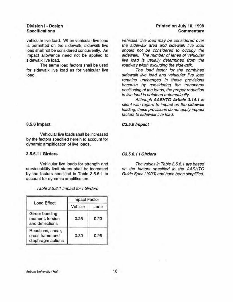
3.5.6 Impact
Vehicular live loads shall be increased by the factors specified herein to account for dynamic amplification of live loads.
3.5.6.1 I Girders
Vehicular live loads for strength and serviceability limit states shall be increased by the factors specified in Table 3.5.6.1 to account for dynamic amplification.
Table 3.5.6.1 Impact for I Girders
Load Effect Impact Factor
Vehicle Lane
Girder bending moment, torsion 0.25 0.20 and deflections
Reactions, shear, cross frame and 0.30 0.25 diaphragm actions
Auburn University / Hall 16
Printed on July 10, 1998 Commentary
vehicular live load may be considered over the sidewalk area and sidewalk live load should not be considered to occupy the sidewalk. The number of lanes of vehicular live load is usually determined from the roadway width excluding the sidewalk.
The load factor for the combined sidewalk live load and vehicular live load remains unchanged in these provisions because by considering the transverse positioning of the loads, the proper reduction in live load is obtained automatically.
Although AASHTO Article 3.14.1 is silent with regard to impact on the sidewalk loading, these provisions do not apply impact factors to sidewalk live load.
C3.S.6 Impact
C3.S.6.1 I Girders
The values in Table 3.5.6.1 are based on the factors specified in the AASHTO Guide Spec (1993) and have been simplified.
Division I - Design Specifications
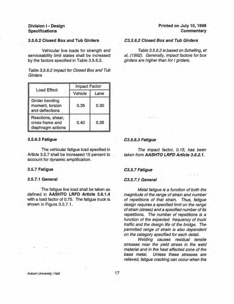
3.5.6.2 Closed Box and Tub Girders
Vehicular live loads for strength and serviceability limit states shall be increased by the factors specified in Table 3.5.6.2.
Table 3.5.6.2 Impact for Closed Box and Tub Girders
Load Effect Impact Factor
Vehicle Lane
Girder bending moment, torsion 0.35 0.30 and deflections
Reactions, shear, cross frame and 0.40 0.35 diaphragm actions
3.5.6.3 Fatigue
The vehicular fatigue load specified in Article 3.5.7 shall be increased 15 percent to account for dynamic amplification.
3.5.7 Fatigue
3.5.7.1 General
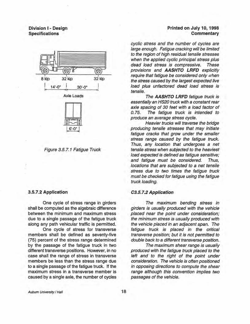
The fatigue live load shall be taken as defined in AASHTO LRFD Article 3.6.1.4 with a load factor of 0.75. The fatigue truck is shown in Figure 3.5.7.1.
Auburn University I Hall 17
Printed on July 10, 1998 Commentary
C3.S.6.2 Closed Box and Tub Girders
Table 3.5.6.2 is based on Schelling, et ai, (1992). Generally, impact factors for box girders are higher than for I girders.
C3.S.6.3 Fatigue
The impact factor, O. 15, has been taken from AASHTO LRFD Article 3.6.2.1.
C3.S.7 Fatigue
C3.S. 7. 1 General
Metal fatigue is a function of both the magnitude of the range of strain and number of repetitions of that strain. Thus, fatigue design requires a specified limit on the range of strain (stress) and a specified number of its repetitions. The number of repetitions is a function of the expected frequency of truck traffic and the design life of the bridge. The permitted range of strain is also dependent on the category specified for each detail.
Welding causes residual tensile stresses near the yield stress in the weld material and in the heat affected zone of the base metal. Unless these stresses are relieved, fatigue cracking can occur when the
Division I - Design Specifications
8 kip
I ,. 14'-0·
32 kip
I 30'-0·
Axle Loads
W 1. 6'-0 •• 1
32 kip
I ".
Figure 3.5.7. 1 Fatigue Truck
3.5.7.2 Application
One cycle of stress range in girders shall be computed as the algebraic difference between the minimum and maximum stress due to a single passage of the fatigue truck along any path vehicular traffic is permitted.
One cycle of stress for transverse members shall be defined as seventy-five (75) percent of the stress range determined by the passage of the fatigue truck in two different transverse positions. However, in no case shall the range of stress in transverse members be less than the stress range due to a single passage of the fatigue truck. If the maximum stress in a transverse member is caused by a single axle, the number of cycles
Auburn University / Hall 18
Printed on July 10,1998 Commentary
cyclic stress and the number of cycles are large enough. Fatigue cracking will be limited to the region of high residual tensile stresses when the applied cyclic principal stress plus dead load stress is compressive. These provisions and AASHTO LRFD explicitly require that fatigue be considered only when the stress caused by the largest expected live load plus unfactored dead load stress is tensile.
The AASHTO LRFD fatigue truck is essentially an HS20 truck with a constant rear axle spacing of 30 feet with a load factor of 0.75. The fatigue truck is intended to produce an average stress cycle.
Heavier trucks will traverse the bridge producing tensile stresses that may initiate fatigue cracks that grow under the smaller stress range caused by the fatigue truck. Thus, any location that undergoes a net tensile stress when subjected to the heaviest load expected is defined as fatigue sensitive; and fatigue must be considered. Thus, locations that are subjected to a net tensile stress due to two times the fatigue truck must be checked for fatigue using the fatigue truck loading.
C3.S.7.2 Application
The maximum bending stress in girders is usually produced with the vehicle placed near the pOint under consideration; the minimum stress is usually produced with the vehicle placed in an adjacent span. The fatigue truck is placed in the critical transverse position; but it is not permitted to double back to a different transverse position.
The maximum shear range is usually produced with the fatigue truck placed to the left and to the right of the point under consideration. The vehicle is often positioned in opposing directions to compute the shear range although this convention implies two passages of the vehicle.
Division I - Design Specifications
of stress range shall be equal to two times the number of truck passages.
3.6 Thermal Loads
Load effects in the superstructure shall be determined for uniform temperature changes as specified in AASHTO Article 3.16.
A uniform temperature difference of 25 degrees Fahrenheit between the deck and the girders shall be considered when the width of the deck is less than one-fifth of the longest span. The load effects due to the temperature differential shall be added to the effects due to the temperature changes specified in AASHTO Article 3.16.
Aubum University / Hall 19
Printed on July 10, 1998 Commentary
Cross frames and diaphragms connecting adjacent girders are stressed when one girder deflects with respect to the adjacent girder connected by the cross frame or diaphragm. The sense of stress is reversed when the vehicle is placed over the adjacent girder. These two transverse positions of the vehicle usually create the largest stress range in radially oriented members. To simulate such a stress cycle, two vehicles traverse the bridge in adjacent lanes. The provisions account for such a cycle by computing the stress range assuming two transverse positions and applying a factor of 0.75 to account for the probability of two vehicles in the critical relative position. There is no allowance for the fact that two trucks are required. When the design fatigue life is less than the fatigue limit, the Engineer may wish to consider a reduction in the number of cycles.
C3.6 Thermal Loads
Although temperature changes in a bridge do not occur uniformly, bridges generally are designed for an assumed uniform temperature change. The orientation of bearing guides and the freedom of bearing movement is important to thermal forces. Sharp curvature and sharply skewed supports can cause excessive lateral thermal forces at supports if only tangential movement is permitted. Wide bridges are particularly prone to large lateral thermal forces because the bridge expands radially as well as longitudinally.
Orienting bearing guides toward a "fixed point" and allowing the bridge to move freely along rays emanating from the fixed point causes thermal forces to be zero if the structure changes temperature uniformly. However, there are other load conditions that may affect decisions regarding bearing orientation.
Division I - Design Specifications
Aubum University / Hall 20
Printed on July 10,1998 Commentary
The requirement to consider a 25 degree Fahrenheit temperature difference between deck and steel addresses the relative time lag that occurs with regard to temperature changes. Since the steel is less massive than the concrete, it changes temperature faster (Krauss and Rogalla, 1996). This temperature differential is particularly important in narrow bridges where a significant difference in vertical reactions may occur.
There is evidence that this temperature differential may contribute to early deck transverse cracking (Krauss and Rogalla, 1996). The engineer may wish to include the deck stress from this loading when checking the need for reinforcement according to Article 2.4.3.
Division I - Design Specifications
4 Structural Analysis
4.1 General
The moments, shears and other load effects required to proportion the superstructure components shall be based on a rational analysis of the entire superstructure.
The entire superstructure, including bearings, shall be considered as an integral structural unit. Analyses may be based on elastic small-deflection theory, unless more rigorous approaches are deemed necessary by the Engineer.
Analyses shall consider bearing orientation and restraint of bearings afforded by the substructure. These load effects shall be considered in designing bearings, cross frames, diaphragms, bracing and deck.
4.2 Neglect of Curvature Effects
4.2.1 I Girders
The effects of curvature may be ignored in the determination of vertical bending moment in I girder bridges when the following three conditions are met:
• Girders are concentric • Bearings are not skewed more
Auburn University / Hall 21
Printed on July 10,1998 Commentary
C4 Structural Analysis
C4.1 General
Since equilibrium of curved I girders is developed by the transfer of load between girders, the analysis must recognize the integrated behavior of all structural components. Equilibrium of curved box girders may be less dependent on the interaction between girders. BraCing elements are considered primary members in curved bridges since they transmit forces necessary to provide equilibrium.
The deck acts in bending, vertical shear and horizontal shear. Torsion increases the horizontal deck shear, particularly in box girders. The lateral restraint of the bearings may also cause horizontal shear in the deck.
Small-deflection theory is adequate for the analysis of most curved girder bridges. However, curved I girders are prone to deflect laterally when the girders are insufficiently braced during erection. This behavior may not be well recognized by small-deflection theory.
C4.2 Neglect of Curvature Effects
This article applies only to vertical bending moment. It does not apply to lateral flange bending, torsion or shear which should always be examined with respect to curvature.
C4.2.1 I Girders
If a line girder analysis is appropriate, the wheel load distribution factor of S/S.S is to be used because the new methods in AASHTO (1994) and AASHTO LRFD (1994) may underestimate live load moments in the girder on the outside of the curve, Hall and Yoo (1996b). Non-composite dead load
Division I - Design Specifications
than 10 degrees from radial • The arc span divided by the girder
radius is less than 0.06 radians where the arc span, Las' shall be taken as follows:
For simple spans: Las = average arc length of all girders in
the cross section,
For continuous end-spans: Las = 0.9 times the arc length of all
girders in the cross section,
For continuous interior spans: Las = 0.8 times average arc length of all
girders in the cross section.
An I girder in a bridge satisfying these criteria may be analyzed as an individual straight girder with span length equal to the arc length. Live load shall be applied to each I girder assuming a wheel-load distribution factor of S/S.S for computing vertical moment, shear and vertical deflection. Non-composite dead loads preferably shall be applied to each girder by assuming a simple-span distribution of load between girders.
The effect of curvature on strength and stability shall be considered for all curved I girders.
Cross frame members shall be designed in accordance with Articles 9.3 and 11.1 for forces computed by the V-load method or other rational means.
Cross frame shall be set to limit lateral flange bending in the girders.
If a line girder analysis is appropriate, Equation (4-1) may be appropriate for determining the lateral bending moment in I girder flanges due to curvature.
6M 12 M,at =--
5RD
Auburn University I Hall
(4-1 )
22
Printed on July 10, 1998 Commentary
preferably is to be distributed to the girders using a simple span assumption since the deck is not effective. Certain dead loads applied to the composite bridge may be distributed uniformly to the girders as provided in AASHTO Article 3.23.2.3. However, heavier concentrated line loads such as parapets, sidewalks, barriers or sound walls should not be distributed equally to the girders. Engineering judgment must be used in determining the distribution of these loads. Often the largest portion of the load on an overhang is assigned to the extenor girder. The exterior girder on the outside of the curve is often critical in curved girder bridges.
The effect of curvature on the torsional behavior of a girder must be considered regardless of the amount of curvature since stability and strength of curved girders is different from that of straight girders, Hall and Yoo (1996b). If a line girder analysis is appropriate and the cross frame spacing is nearly uniform, Equation (4-1) may be appropriate for determining the lateral flange moment in I girder flanges due only to curvature. The resulting lateral flange bending stresses due to curvature can then be subtracted from the total lateral flange stresses from the analysis to compute f m
used to calculate the Pw factors in Articles 5.2.1 and 5.2.2.
Other conditions that produce torsion, such as skew, should be dealt with by other analytical means which generally involve a refined analysis.
Bridges with even slight curvature may develop large radial forces at the abutment bearings. Therefore, thermal analYSis of all curved bridges is recommended.
Division I - Design Specifications
where:
M,at = lateral flange bending moment (k-ft) M = vertical bending moment (k-ft) f = unbraced length (ft) R = girder radius (ft) o = girder depth (in)
Webs shall be designed according to the provisions of Article 6.
4.2.2 Closed Box and Tub Girders
The effect of curvature may be ignored in the determination of vertical bending moment in box girder bridges when the following three conditions are met:
• Girders are concentric, • Bearings are not skewed, and • The arc span divided by the girder
radius is less than 0.3 radians and the average girder height is less than the width of the box where the arc span, Las' shall be taken as defined in Article 4.2.1.
4.3 Methods
4.3.1 Approximate Methods
Approximate analysis methods may be used for analysis of curved girder bridges. The Engineer shall ascertain that the approximate analysis method used is appropriate by confirming that results from the analysis are consistent with the principles defined in Article 1.2.
Auburn University / Hall 23
Printed on July 10, 1998 Commentary
C4.2.2 Closed Box and Tub Girders
Although box-shaped girders have not been examined as carefully as I girders with regard to approximate methods, bending moments in closed girders are less affected by curvature than are I girders, Tung and Fountain (1970). However, torsion is much greater so web shear are affected by torsion due to curvature, skew or loads applied away from the shear center of the box. Double bearings resist significant torque compared to a box-centered single bearing.
C4.3 Methods
C4.3.1 Approximate Methods
The V-load method (1984) has been a widely used approximate method for analyzing horizontally curved I girder bridges. The method assumes that the internal torsional load on the bridge--resulting solely from the curvature--is resisted by selfequilibrating sets of shears between adjacent girders. The V-load method does not directly account for sources of torque other than curvature and the method does not account for the horizontal shear stiffness of the concrete deck. The method is only valid for loads such as normal highway loadings. For exceptional loadings, a more refined analysis
Division I • Design Specifications
4.3.2 Refined Methods
Refined methods of analysis shall be used unless the Engineer determines approximate methods referred to in Article 4.3.1 are acceptable. Refined methods of analysis shall include any structural analysis that considers the entire superstructure as an integral unit and provides the required deflections and actions.
Loads may be applied directly to the structural model, or applied to influence lines, or influence surfaces.
If stresses, rather than girder actions such as moments and shears are determined
Auburn University I Hall 24
Printed on July 10, 1998 Commentary
is required. The method assumes a linear distribution of girder shears across the bridge section: thus, the girders at a given cross section should have approximately the same vertical stiffnesses. The V-load method is also not directly applicable to structures with reverse curvature or to a closed-framed system with horizontal lateral bracing near, or in the plane of one or both flanges. The Vload method does not directly account for girder twist; thus, lateral deflections, which become important on bridges with large spans and/or sharp skews and vertical deflections may be significantly underestimated. The method is best suited for preliminary design, but may also be suitable for final design of structures with radial supports or supports skewed less than approximately 10 degrees.
The M/R method provides a means to account for the effect of curvature in curved box girder bridges. The method and suggested limitations on its use are discussed by Tung and Fountain (1970).
Strict rules and limitations on the applicability of both of these approximate methods do not exist. The Engineer must determine when approximate method: of analysis are appropriate.
C4.3.2 Refined Methods
Refined analysis methods are generally computer based. The finite strip and finite element methods have been the most common. The finite strip method is less rigorous than the finite element method and has fallen into disuse with the advent of more powerful computers. Finite element programs may provide grid analyses using a series of beam elements connected in a plane. Refinements of the grid model may include offset elements. Frequently, the torsional warping degree of freedom is not available in beam elements. The finite
Division I - Design Specifications
from an analysis, the stresses may be compared directly to permitted service stresses or permitted fatigue stress ranges.
4.4 Uplift
If lift-off is indicated, the analysis shall recognize the vertical freedom of the girder at that bearing.
Aubum University / Hall 25
Printed on July 10, 1998 Commentary
element method may be applied to a threedimensional model of the superstructure. A variety of elements may be used in this type of model. The three-dimensional model may be made capable of recognizing warping torsion by modeling each girder cross section with a series of elements.
The stiffness of supports, including lateral restraint such as integral abutments or integral piers, should be recognized in the analysis. Since bearing restraint is offset from the neutral axis of the girders, large lateral forces at the bearings often occur and may create significant bending in the girders.
The Engineer should ascertain that dead loads are applied as accurately as possible and consistent with the requirements of Article 3.2. Only when small-deflection elastic solutions are used, are influence surfaces or influence lines appropriate.
The resulting stresses from 3D finite element methods may be compared directly to the critical stresses determined according to the provisions.
The restraint of girders at supports may lead to lower girder moments than would be computed if the restraints are not present. The Engineer should ascertain that any such benefit recognized in the design will be present throughout the useful life of the bridge.
C4.4 Uplift
When lift-off is indicated, the analysis must be modified to recognize the absence of vertical restraint at the particular support. Otherwise, deflections, reactions and other actions are incorrect. Lift-off is most likely to occur during sequential placement of the deck. Unless lift-off occurs for all loads, liftoff is considered a non-linearity and superposition does not apply.
Division I - Design Specifications
4.5 Concrete
4.5.1 General
Concrete shall be assumed effective in compression, tension, flexural shear and in-plane shear for determining the global stiffness used to generate moments, shears, reactions and torsion.
The entire cross sectional area of concrete associated with a girder preferably shall be considered effective in the analysis. Shear lag shall be considered.
4.5.2 Stresses In Composite Sections
The uncracked section shall be assumed for positive live load moment applied to a composite section when checking all limit states.
The cracked section shall be assumed for negative live load moment applied to a composite section when checking the strength limit state. If superimposed dead load has produced compression in the deck in this case, the superimposed dead load may be applied to the uncracked section.
The uncracked section shall be assumed for positive and negative moments for checking fatigue, serviceability and constructibility limit states.
The deck may be assumed to be placed at one time on the non-composite structure when computing stresses at the
Auburn University / Hall 26
C4.S Concrete
C4.S.1 General
Printed on July 10, 1998 Commentary
Field measurements confirm that deck concrete on stringer bridges is effective in tension for typical magnitudes of live load, Yen, et aI, (1995). This behavior is consistent with analysis of reinforced concrete structures where stiffness is often computed with the assumption that concrete is effective in tension. The effect of this assumption is to cause an increase in negative moments and a slight reduction in the positive moment" in continuous girders compared to the mort ~;
from analyses which ignore concrei • .; m tension.
Shear lag should be considered when the girder spacing is extremely large such as found with girder floor-beam bridges. In these cases the AASHTO (1989) Guide Spec for Design of Concrete Segmental Bridges can be used to determine the effective width of concrete.
C4.S.2 Stresses in Composite Sections
Both positive and negative live load moments are applied to nearly all points in a continuous girder bridge. Thus, points of contraflexure have little meaning. The provisions call for positive live load moments to be applied to the uncracked composite section. This requirement is consistent with AASHTO Article 10.38.4 that composite girders are to be designed as composite along their entire length.
Negative live load moments are applied to the cracked composite section for the strength limit state regardless of the deck stress due to superimposed dead load applied to the composite section. However, if the magnitude of the dead load deck compressive stress is greater than the live load tensile stress, the section should remain
Division I - Design Specifications
strength limit state. Girder stresses due to vertical
bending and lateral flange bending acting on the non-composite and composite sections shall be accumulated for checking all limit states.
When computing section properties of composite sections, the effective width of concrete deck may be the girder spacing for interior I girders and may be one-half of the girder spacing plus the overhang width for exterior I girders. For box girders, the entire deck width between webs of the box also shall be included.
Lateral bending stresses need not be considered in the concrete deck. When a cast-in-place deck is used, lateral bending stresses in the top flange of the girders need not be considered after the deck has hardened.
When torsion is applied to a composite box girder, the concrete shall be assumed effective with the top flange bracing in resisting torsional shear for all limit states, whether the girder is in positive or negative bending.
Printed on July 10, 1998 Commentary
uncracked for the negative live load moment. The uncracked section is used for the
limit states other than strength because field data substantiates that the stresses in the steel are best predicted with an uncracked section assumption, Yen, et aI, (1995).
The deck may be assumed to be placed at once when checking strength limit state because that has been the traditional practice. Creep of concrete leads to this condition over time.
Stresses developed in the noncomposite girder are assumed to remain and stresses developed in the composite girder are assumed to remain. Total stresses may not be determined by applying the sum of the non-composite and composite moments to the composite section.
The entire deck width is used to compute section properties based on analytical findings and field measurements such as those by Yen, et ai, (1995) who report that the entire 9.5-inch thick deck was effective in positive and negative moment regions on a bridge with 15-foot girder spacing.
Top flanges are usually continuously restrained by the hardened concrete. The locked-in lateral flange stresses due to the non-composite loads are ignored after the concrete has hardened. When precast deck panels are used, the Engineer may choose not to ignore the non-composite lateral flange stresses in the top flange, particularly if the flange is not continuously supported by the deck.
Shear connectors are required along the entire girder length according to Article 7.1, because the composite section can be assumed capable of resisting torsion at any point.
Friction forces caused by transverse The most common applications of
Aubum University / Hall 27
Division I • Design Specifications
prestressing of the deck in girders, cross frames, diaphragms and bearings shall be considered.
Longitudinal prestressing of the deck preferably shall be in conjunction with a precast deck and performed prior to making the deck sections composite with the girders. The friction between the precast deck sections and the steel girders shall be considered.
When longitudinal post-tensioning is performed after the deck becomes composite with the girders, additional forces induced in the steel girders and shear connectors shall be considered.
The effect of differential creep and shrinkage of the concrete shall be considered. The Poisson effect shall be considered.
4.6 Construction Stages
The structure shall be analyzed for each critical stage of construction to ensure its stability and to ensure it has adequate strength.
When checking deck stresses, the uncracked section shall be used with the modular ratio, n, ignoring creep.
Aubum University I Hall 28
Printed on July 10, 1998 Commentary
prestressed concrete in curved steel girder bridges is transverse post-tensioning of the deck and integral pier caps having the tendons penetrate the girder webs. When a composite deck is prestressed longitudinally, the shear connectors transfer force to the steel. The long-term effect of creep around the shear connectors should be evaluatl~rJ to ensure that the composite girder is abit?i to recognize the prestressing over the life of the bridge.
The Po~son effect recogn~es the bulging of concrete when subjected to prestressing. When used in pier caps, posttensioning causes a transverse Poisson tensile stress resulting in the longitudinal stress in the steel stringer.
C4.6 Construction Stages
Analyses of the stages of erection can be used to ascertain that the field sections can be properly fit up without introducing significant stresses that were not considered in the design.
Division I - Design Specifications
5 Flanges With One Web
5.1 General
The provisions of this article apply to a single horizontally curved rectangular flange having a single vertical or inclined web attached at mid-width of the flange. The flange may be either compact or noncompact and either continuously or partially braced.
Flanges shall be proportioned at the strength limit state to satisfy the critical average stress, Fer' specified in Articles 5.2, 5.3 or 5.4, as applicable.
The flange size within a panel preferably shall be constant with changes in flange size preferably made near panel brace points. The smallest flange width, b f , and the smallest flange radius, R, within a panel shall be used to compute Fer for partially braced flanges.
fb shall be defined as the largest computed factored average flange stress in kips per square inch at either brace point. f, shall be defined as the total factored lateral flange bending stress due to curvature and due to effects other than curvature at the critical brace point. The sign of fb is positive when the stress is tensile. The sign of f, is positive when f, at the flange tip away from the center of curvature is tensile and negative when f, at the flange tip away from the center of curvature is compressive.
The unbraced length, f, is the distance between brace points at cross frames or diaphragms. f shall not be greater than 2Sbf • Partially braced flanges shall be braced at intervals such that R If shall be not less than 10.
The absolute value of the bending stress ratio, Ifqlfbl, at brace points shall not exceed 0.5 when fb is greater than or equal to O.SFer. Where fb is less than O.SF r in tension or compression, the ratio, I fq IfJ is
Auburn University / Hall 29
Printed on July 10,1998 Commentary
CS Flanges With One Web
CS.1 General
The research from which Equations (S-1) and (S-S) were derived was based on doubly-symmetric prismatic compact and non-compact, partially braced curved I sections subjected to nearly uniform moment, McManus (1971). Second-order effects including amplification of lateral flange bending, cross section deformation and arching were considered in the development of the p factors. The work has been extended successfully to singly symmetrical I sections and to top flanges of tub girders in the AASHTO (1993) Curved Girder Guide Spec.
Flanges with webs located at other than mid-width of the flange should not be used on I girders without special investigation of lateral flange bending effects.
The strength equations were not developed for the case of a change of flange size within a panel. As a practical matter, changes of flange size that are not near brace pOints can be assumed to be constant over the panel, using the smaller flange. The sign convention used for the lateral bending stress and vertical bending stress is that of Dabrowski (1968); if torsion is due to only curvature, the ratio of lateral flange bending stress to average flange stress is positive at brace point. McManus (1971) used the opposite sign convention.
The limits imposed on the nondimensional parameters are those used in development of the equations, McManus (1971). Other parameters limited in the research but not specified include: web-toflange areas between 1.0 and 1.3; web-toflange thickness between 1.0 and 3.0: and yield stress between 36 and SO ksi. Compact sections with web slenderness up to 1S0 and non-compact sections with web slenderness
Division I - Design Specifications
unlimited. In no case shall fp exceed 0.5Fy' where F{ equals the specified minimum yield stress 0 the flange.
5.2 Partially Braced Compression Flanges
Flanges not braced continuously by hardened concrete shall be considered partially braced. A brace point shall be defined as any point when adequate resistance against lateral deflection and rotation of the flange is provided.
5.2.1 Compact Flanges
The flange is compact when the specified minimum yield stress does not exceed 50 ksi, and the width-to-thickness ratio of the flange does not exceed 18.
The critical average flange stress, Fer' shall be taken as the smaller of Fer1 or Fef2 ,
(5-1 )
where:
1 Pb
1 + 12"( 1 + 2") (!... -0.01) 2 b, b, R
Auburn University I Hall 30
Printed on July 10,1998 Commentary
Up to 165 were studied, Brogan (1972), Culver, et aI, (1972). Extreme deviation from any of these parameters is not advisable.
The ratio, I ~ Ifb I, is limited only when the computed average flange stress is greater than 0.5 Fer because the applicability of flange strength equations are limited. There is no need to limit the ratio when fb is small.
CS.2 Partially Braced Compression Flanges
Rotational restraint of the flange at the brace points is implicit in the McManus (1971) study because equal panel lengths were assumed. Typical flange bracing provided by cross frames or diaphragms designed and detailed according to Article 9.3 should be adequate to restrain the flange.
CS.2.1 Compact Flanges
The original research acknowledged plastic moment for compact sections. The shape factor of 1. 13 for doubly symmetrical I girder is the reason that the critical stress mal... exceed Fy • However, the product, Pb Pw' may not exceed 1.0, which limits Fer to Fbs '
The web and tension flange are not considered when determining the compactness of a flange in this article.
Since the McManus (1971) '<
considered lateral flange bending stress iJS
an integral part of the P factors, lateral flange bending stress due to curvature should not be included when computing P factors, Hall and Yoo (1996a). Lateral flange bending due to sources other than curvature must be considered.
Compact flanges are limited to steels having a specific minimum yield stress not greater than 50 ksi as required in AASHTO LRFD (1996).
Research by Davidson, et ai, (1996)
Division I - Design Specifications
where:
f = distance between along girder arc (ft)
brace
R = minimum radius in panel (ft)
points
fm = factored lateral flange bending stress at critical brace point due to effects other than cUlvature (ksi)
fb = factored average axial flange stress at either brace pOint (ksi)
The critical average flange stress of an equivalent straight girder flange, Fbs (ksi), shall be taken as:
(5-2)
where:
Fy = specified minimum yield stress (ksi)
E = Young's modulus (ksi)
Flange width, b" shall be taken as O.9b, when determining II if the cross section is not doubly symmetric.
(5-3)
where:
f, = fw + fm fw = factored warping stress due to
curvature at critical brace point (ksi)
Aubum University / Hall 31
Printed on July 10,1998 Commentary
indicates local buckling of curved girder flanges may be more critical than for straight flanges. Tests of curved girders also indicate that local buckling is critical when b,ft, is greater than 23, Culver and Nasir (1969) and Mozer and Culver (1975). The flange widthto-thickness limit has been liberalized to 18 for compact flange which is the value used in AASHTO LRFD Article 6.10.5.2.1 for Fy= 50 ksi. The curved girder research indicates that a maximum value of 18 is prudent.
Warping stress due to curvature is not included in f m because that assumption was made in the derivation, McManus (1971) and Hall and Yoo (1996a). Thus, if the torsion is only due to curvature, f m equals zero. McManus studied curved I girder framing that had concentric girders with radial supports and bracing at equal increments. Uniform moment was also assumed. These are the conditions that are assumed in the V-load methodology. When a refined analysis yields lateral bending moments significantly different from those computed according to Equation (4-1), the difference is due to effects other than curvature.
Possible causes of f m include any torsion resulting from such sources as the skewed supports and eccentricity of the deck weight on the overhang brackets, deck forms, screed rail, sound barrier, utilities, and sign posts.
The Culver and McManus (1971) work applies empirical p factors to the lateral torsional buckling equation, Equation (5-2), for straight girder flanges that was specified by AASHO at that time. Thus, the same lateral torsional buckling equation must be retained.
The flange width is multiplied by 0.9 when the section is singly symmetric as prescribed in those AASHO provisions. Equation (5-2) is applicable only when FbS is greater than 0.5 Fy , which is the typical case. The Euler hyperbola might be used to obtain
Division I - Design Specifications
5.2.2 Non-compact Flanges
The width-to-thickness ratio of the flange shall satisfy Equation (5-4).
(5-4)
where:
t, = flange thickness (in)
The critical average flange stress, Fer' shall be taken as the smaller of Fer1 or Fer2 .
where:
Pw1=
1
1 +.!... 121 R b,
1
Aubum University / Hall
(5-5)
32
Printed on July 10, 1998 Commentary
critical stresses less than O.5Fy .
Compact flanges are assumed to yield due to a combination of vertical bending stress and lateral bending stress. The limit on the combined stress given by Equation (5-3) is derived from the plastic capacity of the combined lateral flange bending and vertical bending, Hall and Yoo (1996a) and Schilling (1996). A small portion of the web is permitted to yield. Yielding of the web can be prevented if one-half of the lateral flange bending stress is used instead of one-third in Equation (5-3), Schilling (1996).
C5.2.2 Non-compact Flanges
Non-compact flanges are defined as those that are permitted to reach the peak yield stress in the flange tip without local buckling.
The width-to-thickness ratio of the flange shall satisfy Equation (5-4).
The critical average flange stress shall be taken as the smaller of Ferl or Fef2 ,
where:
Pb , Pw are defined in Article 5.2.1
1 Fef2 = Fy --I f,l
3
5.4 Continuously Braced Flanges
(5-7)
(5-8)
The width-to-thickness ratio of the flange shall satisfy Equation (5-4)for conditions that exist when the flange is partially braced. The critical average flange stress in tension or compression, Fer' for the continuously braced flange equals the specified minimum yield stress, Fy • Lateral flange bending stresses need not be considered after the
Auburn University / Hall 33
Compactness has no meaning for a tension flange. An arbitrary flange slendemess has been set equal to the noncompact criterion to ensure that flanges will not distort excessively when welded to the web.
Since the research was performed on doubly-symmetric sections, tension flanges were not specifically considered. These provisions rather arbitrarily determine the critical tensile stress by applying the compact P factors to Fy , which is conservative since the tension flange tends to straighten rather than increase its curvature. Like the compact compression flange, the sum of the normal stress plus one-third of the lateral flange stress may not exceed Fy •
CS.4 Continuously Braced Flanges
Continuously braced flanges usually occur when a flange is encased in concrete. The average longitudinal flange stress is limited to Fy without consideration of lateral bending.
Additional lateral bending stresses do not develop once the concrete has hardened. Lateral bending stress in the flange prior to
Division I - Design Specifications
flange is continuously braced.
Auburn University I Hall 34
Printed on July 10, 1998 Commentary
the deck hardening may remain. Neglecting these stresses may be unconservative. The deck capacity is more than adequate to compensate for any lateral force that may be shed from a flange tip that yields prematurely.
Flanges need to be checked for the construction conditions defined in Articles 13.2 and 13.7 prior to the deck hardening.
Flange slenderness is limited to meet non-compact slenderness provisions prior to the deck hardening, the flange is designed as a non-compact flange to ensure it does not undergo yielding during construction.
Division I - Design Specifications
6 Webs
6.1 General
Webs shall be designed for longitudinal stress and the total shear in the girder. Longitudinal stress in the web shall equal the sum of stresses due to the appropriate factored loads acting on the respective cross sections. The maximum tensile longitudinal stress in the web due to the factored load groups shall not exceed Fy •
Webs may be curved about a vertical axis. Webs may be inclined, or vertical. The shear in an inclined web shall be determined by adjusting for the inclination.
6.2 Unstiffened Webs
Web slenderness, D Itw ' shall not exceed 100 for girders with minimum radius in the panel not greater than 700 feet. Slenderness of webs with minimum radius in the panel greater than 700 feet shall satisfy:
D - s 100 + 0.038(R - 700) s 150 (6-1) tw
where:
D = distance along the web between flanges (in)
tw = web thickness (in) R = minimum radius in the panel (ft)
Auburn University I Hall 35
C6Webs
C6.1 General
Printed on July 10, 1998 Commentary
Tests of curved girders indicate that analytical models for the elastic buckling of flat webs can be used safely for the design of curved webs within the limitations of this specification. Web strengths based on elastic shear and bend-buckling used in the Guide Spec have been retained in these provisions.
A web plate should be developable which means it can be formed as part of either a cylinder or a cone. The web should not be curved about a longitudinal axis.
When the web is inclined the web shear is determined from the vertical shear by dividing by the cosine of the angle the web makes with the vertical plane. The distance along the web is used on inclined webs rather than the vertical distance.
C6.2 Unstiffened Webs
The maximum web slenderness is limited only by D Itw and the radius of the web panel.
There are no tests of unstiffened curved girders with web slenderness greater than about 70. Therefore, web slenderness of this type of girder web has been reduced from that used for straight girders. Web slenderness of girders with radius less than 700 feet is limited to 100, which is approximately the slenderness limit for compact webs having a yield stress of up to 50 ksi according to AASHTO LRFD. Permitted web slenderness increases linearly with respect to reduced curvature up to a maximum of 150 at a radius of 2,000 feet.
There is evidence suggesting that transverse stiffeners help retain the cross section shape of curved girders, Yoo (1996). Although, elastic bend-buckling of flat plates is not related to transverse stiffener spacing
Division I - Design Specifications
6.2.1 Bending Stresses
The critical compressive longitudinal stress in the web. Fer. shall be taken as:
where:
k = bend-buckling coefficient := 7.2(DIDe)2 ~ 7.2
(6-2)
Dc = depth of web in compression (in)
Auburn University / Hall 36
Printed on July 10, 1998 Commentary
of flat plates, there is some evidence that transverse stiffeners improve the bending capacity of curved webs, Nakai, et ai, (1984), Yoo (1996).
C6.2.1 Bending Stresses
Elastic bend-buckling is investigated for each limit state including constructibility. Flexural and axial stresses in the top and bottom of the web for the non-composite and composite conditions are accumulated which allows the effective neutral axis to be located for each limit state based on the accumulated stresses. Thus, the distance on the web be·tween the compression flange and the et ; .tive neutral axis, Dc' is determined from the sum of the stresses due to the factored loads. In regions of negative bending, the steel section alone may be conservatively used to determine Dc for the section conSisting of the steel girder plus the longitudinal reinforcement.
The bend-buckling coefficient, k, for a flat plate V~':JI top and bottom clamped edges subjected to a symmetrical bending stress pattern is approximately 40, Timoshenko and Gere (1961). The hardened deck approximates a clamped condition. Otherwise, the degree of web clamping is a function of the compression flange rigidity. These provisions set k equal to 28.8 for the symmetrical condition.
Coincident shear and bending is not considered in these provisions. Shear and bending are large simultaneously near interior supports. To provide some conservatism in regions of high shear and bending, the constant has been reduced to 7.2 in Equation (6-2) rather than 9.0 which is used in AASHTO Article 10.61.1, Equation (10-173) for straight girders.
Equation (6-2) is inappropriately conservative when both edges of the web are in compression such that the neutral axis lies
Division I - Design Specifications
6.2.2 Shear Strength
The critical shear strength of the web, Vcr' shall be taken as:
(6-3)
where:
Vp = 0.58F ptw C = ratio of the elastic-shear-buckling
strength to the shear-yield strength
The ratio, C, shall be taken as follows:
c = 1.0 for D < 1.10 ~ Ek. (6-4) tw Fy
(6-5)
for D > 1.38~ Ek. (6-6) tw Fy
Aubum University / Hall 37
Printed on July 10, 1998 Commentary
outside the web which can occur near points of dead load contraflexure when stresses due to moments of opposite sign in noncomposite and composite sections are accumulated. Therefore, the provisions limit the minimum bend-buckling coefficient to 7.2, Timoshenko and Gere (1961). This value is approximately the elastic buckling coefficient for a flat web with clamped flanges and loaded entirely under uniform compression with no shear.
C6.2.2 Shear Strength
Shear strength is divided into three regimes of web slenderness. The most stocky webs are assumed to reach the plastic capacity of the web, Vp. C equals 1.0 in this slenderness range. Shear strength of webs of intermediate slenderness are defined using Equation (6-5) where C is inversely proportional to slenderness and the square root of yield stress.
Shear strength of webs within the elastic range in the most slender web regime is a hyperbolic function of slenderness.
The shear-buckling coefficient, kw, is set equal to 5 for an unstiffened panel, which has an assumed infinite length.
Since the bend-buckling strength has been adjusted for coincident shear, there is no need to adjust the shear strength for coincident bending.
Division I - Design Specifications
where:
kw = shear-buckling coefficient = 5
6.3 Transversely Stiffened Webs
Web slenderness, D Itw ' shall not exceed 150. The actual transverse stiffener spacing, do' shall not exceed O.
At simple supports, the actual stiffener spacing, do' shall not exceed 0.50.
6.3.1 Bending Stresses
The critical compressive longitudinal stress in the web, Fer' shall be taken as:
F" = r~r $ F,
where:
k = bend-buckling coefficient = 9(010e)2;? 7.2
6.3.2 Shear Strength
(6-7)
The critical shear strength, Vcr' shall be taken as defined in Article 6.2.2 except the shear-buckling constant, kw, shall be taken as:
k = 5 w 5
+ --
(~r (6-8)
Aubum University I Hall 38
Printed on July 10, 1998 Commentary
C6.3 Transversely Stiffened Webs
The maximum transverse stiffener spacing, do' is limited to 0, which is consistent with the limit in the Guide Spec (1993) and in Hanshin (1988). There has been no research that indicates a greater spacing of transverse stiffeners is appropriate on curved girder webs.
The maximum spacing of transverse stiffeners at simple supports is conservatively limited to one-half the web depth to provide an anchor panel against buckling.
C6.3.1 Bending Stresses
The bend-buckling constant has been increased to 9.0 from 7.2 for the unstiffened case because transverse stiffeners tend to strengthen curved girder webs, Yoo (1996), and because of the unrecognized postbuckling bending and shear strength of transversely stiffened webs.
A minimum limit of the bend-buckling coefficient equal to 7.2 is provided for Equation (6-7). This value is based on the elastic buckling strength of a plate subjected to uniform compression.
C6.3.2 Shear Strength
The required stiffener spacing, d, is used in Equation (6-8) since it is the value to be determined from Article 6.2.2. The actual stiffener spacing, do' may be less than d because transverse stiffeners are normally uniformly spaced between cross frame connection plates which act as transverse stiffeners.
Division I - Design Specifications
where:
d = required spacing of transverse stiffener (in)
The actual transverse stiffener spacing, do' shall not exceed d, the required spacing.
6.4 Longitudinally and Transversely Stiffened Webs
One or two longitudinal web stiffeners may be used in conjunction with transverse stiffeners when the web slenderness, 0 /tw ' exceeds 150. The web slenderness shall not exceed 300 for a longitudinally stiffened web. Transverse stiffeners shall be spaced according to the provisions of Article 6.3. The panel depth, 0, shall be taken as the distance along the web between flanges.
6.4.1 Bending Stresses
The critical compressive longitudinal stress in the web, Fer' shall be taken as:
F" s r~y s Fy
where:
(6-9)
(6-10)
(6-11 )
Aubum University / Hall 39
Printed on July 10, 1998 Commentary
C6.4 Longitudinally and Transversely Stiffened Webs
I
There has been no research performed on curved girders with longitudinal web stiffeners in the U. S. For this reason, web slenderness is limited to 300 (less than the slenderness permitted for straight girders in AASHTO). There have been several longitudinally stiffened curved girder specimens tested in Japan; and longitudinally stiffened webs are permitted in the Hanshin (1988) Curved Girder Guide Provisions. The maximum web slenderness permitted by Hanshin is approximately 250 for webs with a single longitudinal stiffener. Slendernesses of approximately 300 are permitted with two longitudinal web stiffeners, Hanshin (1988).
C6.4.1 Bending Stresses
The purpose of the longitudinal web stiffener is to restrain the web from elastic bend-buckling in the first mode. By forcing the second mode, the buckling stress is increased. These provisions permit the buckling stress to be computed for a web with a longitudinal stiffener in any vertical location. Thus, non-composite and composite load conditions can be investigated.
Alternately, it is possible to place the stiffener on the web so that the bend-buckling stress is satisfactory with either edge of the web in compression. Since the web must be adequate for several different stress states, and the longitudinal stiffener may be placed
Division I - Design Specifications
where:
ds = distance along web between longitudinal stiffener and compression flange (in)
The bend-buckling coefficient, k, shall not be less than that computed according to the provisions of Article 6.3.1.
6.4.2 Shear .Strength
The critical shear strength, Vcr' shall be taken as that defined by Article 6.3.2.
6.5 Transverse Web Stiffeners
Transverse web stiffeners shall be made of the same material grade as the web to which they are attached. Transverse web stiffeners may be designed singly or in pairs on opposite sides of the web. When single transverse stiffeners are used, they preferably shall be attached to both flanges. When pairs of transverse stiffeners are used, they shall be fitted tightly to both flanges. Stiffeners used as connection plates shall be attached to the flanges by welding or bolting with adequate strength to transfer horizontal force in the cross members to the flanges. The distance between the terminus of the web-to-stiffener weld and the near edge of the web-ta-flange weld shall not be less than 4 tw or more than 6tw•
The width-to-thickness ratio of the outstanding element of transverse web stiffeners shall satisfy:
at inefficient locations that result in very low bend-buckling coefficient from Equations (6-10) and (6-11), the web bend-buckling capacity is not permitted to be less than that of a web with only transverse stiffeners.
C6.4.2 Shear Strength
C6.S Transverse Web Stiffeners
According to these provIsions, transverse stiffeners are designed to force a nodal point to form at each stiffener when the web buckles due to shear loading.
When single transverse stiffeners are used, they are preferably attached to both flanges to prevent torsional buckling of the flanges and to help retain the cross sectional configuration of the girder when subjected to nonuniform torsion. The fitting of pairs of transverse stiffeners firmly against the flanges is required for the same reason.
The minimum width-to-thickness ratio of transverse stiffeners is taken from AASHTO LRFD Article 6.10.8.1.2. The minimum width finds its origin in Ketchum (1920).
The rigidity required by Equation (6-13) against in-plane buckling has an added requirement to account for the radial force that occurs in curved girder webs. This radial force is manifest by the tendency of a curved web to bow away from its center of curvature and is accounted for by the curvature parameter, Z, Hanshin (1988).
Since the required stiffener spacing, d, is used in Equation (6-8) to compute the web shear strength, it is also used to
Division I - Design Specifications
Fy = specified minimum yield stress of stiffener (ksi)
The width of a transverse web stiffener shall be not less than 2 inches plus 0130, nor one-fourth the width of the narrower flange.
The moment of inertia of a single transverse stiffener about the face of the web, or a pair of stiffeners with respect to the mid-plane of the web, 'ts' shall satisfy:
where:
J = [( 1.:8)'_+ L 0.5
where:
a = aspect ratio = diD
(6-13)
(6-14)
x = 1.0 for a s 0.78 (6-15)
X = 1 +( a-0.78)Z4 for 0.78 < as1.0 (6-16) 1,775
where:
Z = 0.079d/ ::; 10 R tw
6.6 Longitudinal Web Stiffeners
(6-17)
Longitudinal web stiffeners shall be made of the same material grade as the web to which they are attached. The vertical location of the stiffener(s) shall be such that the longitudinal stress in the web shall not exceed the critical compressive longitudinal stress determined according to the provisions of Article 6.4.1 for each limit state.
Two longitudinal stiffeners may be used on a web section where stress reversal occurs.
Aubum University / Hall 41
Printed on July 10, 1998 Commentary
compute the required moment of inertia of the transverse stiffener.
The actual stiffener spacing, do, is used to compute Z in Equation (6-17) since this curvature parameter is dependent on the restraint actually provided by the transverse stiffeners.
C6.6 Longitudinal Web Stiffeners
The rigidity required of longitudinal web stiffeners on curved webs is greater than that required for similar stiffeners on straight webs because of the tendency of curved webs to bow. In Equation (6-18), P is a simplification of the requirement in the Hanshin (1988) provisions for longitudinal stiffeners used on curved girders. The required rigidity provided by Equation (6-18) was derived based on the assumption that longitudinal stiffeners are continuous across
Division I - Design Specifications
Longitudinal stiffeners preferably shall be made of a single bar, plate or angle attached on one side of the web. Transverse stiffeners preferably shall be placed on the other side of the web.
Longitudinal stiffeners shall be continuous at transverse stiffeners, connection plates and bearing stiffeners located at the same side of the web. Transverse web elements interrupted by longitudinal stiffeners shall be attached to the longitudinal stiffener with adequate strength to develop the bending and axial strength of the transverse web element across the longitudinal stiffener.
When the longitudinal stiffener is interrupted at transverse web elements, the longitudinal stiffener shall be attached to the transverse web elements to develop the bending and axial strength of the longitudinal stiffener.
The moment of inertia of' the longitudinal stiffener, 'IS' about its neutral axis, including a portion of the web equal to 18tw , shall satisfy:
(6-18)
where:
f3 = z + 1 when the longitudinal stiffener 6 is on side of the web away
from the center of curvature f3 = ..?.. + 1 when the longitudinal stiffener
12 is on side of the web toward the center of curvature
a and Z are defined in Article 6.5
The width-to-thickness ratio of the outstanding element of the longitudinal stiffener shall satisfy Equation (6-12).
Printed on July 10, 1998 Commentary
transverse stiffeners. Thus, transverse stiffeners are best placed on the opposite side of the web from the longitudinal web stiffener to minimize intersections of the stiffeners. At bearing stiffeners and at connection plates where the longitudinal and vertical stiffeners must intersect, the designer may discontinue either the transverse element or the longitudinal stiffener. In either case, the discontinued element must be fitted and attached to both sides of the continuous element with a connection capable of developing the bending and axial strength of the discontinued element. Copes should be provided to avoid intersecting welds. Should the longitudinal stiffener be interrupted, the interruptions must be carefully designed with respect to fatigue.
If the web undergoes stress reversal, it may be desirable, or necessary, to use two longitudinal stiffeners on the web.
6.7 Bearing Stiffeners C6.7 Bearing Stiffeners
Bearing stiffeners shall be placed in These provisions address centrally
Aubum University I Hall 42
Division I - Design Specifications
pairs on the girder web or diaphragm which receive reactions or other concentrated loads. Bearing stiffeners preferably shall be attached to diaphragms rather than inclined webs. Bearing stiffeners may not be required if the web or diaphragm is restrained by concrete. If the web is restrained by concrete, adequate shear connection according to the provisions of Article 7 shall be provided to transfer the reaction or concentrated load between the concrete and the steel elements.
Bearing stiffeners preferably shall consist of pairs of angles bolted to the web or diaphragm, or pairs of bars or plates welded to the web or diaphragm. Bearing stiffeners shall be made of the same or less material grade as the member to which they are attached. The width-to-thickness ratio of the outstanding element shall satisfy Equation (6-12).
The outstanding elements of the bearing stiffener shall extend as near as practical to the edge of the bearing sole plate. Bearing stiffeners shall be milled to fit tightly against either the flange through which they receive the concentrated load, or attached to that flange by a weld of adequate size to transfer the reactions. The stiffener-to-flange weld shall be capable of transmitting the concentrated load according to the provisions of AASHTO Article 10.34.6.1. When the stiffeners are milled to bear, the bearing stress shall not be greater than 1.35Fy •
A centrally located portion of the web or diaphragm equal to 18tw may be considered effective between each pair of bearing stiffeners.
If the concentrated load is applied concentrically with respect to the centroidal axes of the bearing stiffener, the bearing stiffener assembly may be designed as a centrally loaded compression member according to the provisions of AASHTO Article 10.54.1. The effective length factor,
Auburn University / Hall 43
Printed on July 10, 1998 Commentary
loaded and eccentrically loaded bearing stiffeners. The stiffeners may be attached to vertical webs or diaphragms.
When box girders with inclined webs are used, bearing stiffeners should be attached to either an integral or external diaphragm rather than to the webs so that the bearing stiffeners are perpendicular to the sole plate. Bearing stiffeners should be designed for eccentricity due to thermal movements. EccentriCity is usually most critical when bearing stiffeners are attached to diaphragms.
Bearing of the stiffener plates on the bottom flange can be ensured by welding the stiffeners to the bottom flange. The size of weld is to be adequate to transfer the reaction in shear. Full-penetration welds may be used, but are not required when stiffeners are milled.
When concrete diaphragms are used, they are connected with shear connectors to the webs or to a steel diaphragm. The shear connectors should be adequate to transfer the reaction plus any other action considered in the design. However, the reaction should not be carried through the shear connectors without another load path through the steel element since the concrete is likely to creep around the shear connectors.
Any rotation of the girder due to dead load about either axis at the bearing may cause the bearing stiffeners to be unevenly loaded. The girders can be cambered for rotation about the transverse axis and about the longitudinal axis to ensure uniform bearing.
Division I - Design Specifications
K, shall be taken as 0.75. Eccentricity of the concentrated load
with respect to the centroidal axes of the bearing stiffener shall preferably be considered by designing the bearing stiffener assembly as a beam-column according to the provisions of AASHTO Article 10.54.2. The effective length factor, K, shall be taken as 0.75. The equivalent moment factor, C, shall be taken as 1.0.
The final 'attitude at the bearing stiffeners shall be vertical.
Aubum University / Hall 44
Printed on July 10, 1998 Commentary
Division I - Design Specifications
7 Shear Connectors
7.1 General
The ultimate strength of shear connectors shall be determined according to the provisions of Articles 7.2.1 and 7.3.2. Shear connectors shall also satisfy the provisions of AASHTO Article 10.38.2. Shear connectors shall be designed for fatigue according to AASHTO LRFD Articles 6.10.7.4.1b and 6.10.7.4.2, except as modified in Articles 7.2.2 and 7.3.3. Shear connectors shall be provided in negative moment regions. Shear connector pitch preferably shall be uniform between each point of maximum positive live load moment and an adjacent end of the girder and between each point of maximum positive live load moment and the adjacent point of greatest negative moment in continuous spans.
7.2 I Girders
7.2.1 Strength
The minimum number of shear connectors, N, between a point of maximum positive live load moment and an adjacent end of girder shall be computed as:
(7-1 )
where:
¢sc = 0.85 S u = strength of one shear connector
Auburn University / Hall 45
Printed on July 10,1998 Commentary
C7 Shear Connectors
C7.1 General
These strength provisions are based on AASHTO and the fatigue provisions are based on AASHTO LRFD. However, there are additional radial shear forces on the shear connectors in curved bridges that are considered.
Shear connectors are to be provided in negative moment regions because torsional shear exists in the negative moment regions as well as in the positive moment regions and because the deck is assumed to be uncracked in negative moment regions for serviceability, fatigue and constructibility limit states. Shear connectors also help control cracking when the deck is subjected to tensile stress and has longitudinal reinforcement.
There is no known occurrence in the field of a fatigue failure in a tension flange at shear connector welds when shear connectors have been provided over the entire girder. There have been fatigue failures of shear connectors on tension flanges when shear connectors were terminated at the point of dead load can tra flexure .
C7.2 I Girders
C7.2.1 Strength
The number of shear connectors between a simple support and the adjacent point of maximum positive live load moment is based on AASHTO Article 10.38.5 and the modifications given herein. The point of maximum positive live load moment is specified because it applies to the composite section and is easier to locate than a maximum of the sum of the moments acting on the composite section.
The radial effect of curvature is
Division I - Design S! " 'clfications
according to AASHTO Article 10.38.5.1.2 (kip)
P = force in slab at point of maximum positive live load moment by Equation (7-2) (kip)
where:
p= p
F= p
where:
P = (f5"/ + F/ (7-2)
longitudinal force in the slab computed as the smaller of P1p. or P
2P from Equations (7-3) and (7-4)
(kip) radial force in the slab computed from Equation (7-5) (kip)
(7-3)
As = area of steel girder (iri)
(7-4)
where:
f~ = specified 28-day compressive stress of concrete (ksi)
b d = effective concrete width as specified in Article 4.5.2 (in)
td = average concrete thickness (in)
where:
L = p
- - L Fp = P ....E. (7-5)
p R
arc length between an end of the girder and an adjacent point of maximum positive live load moment (ft)
R = smallest girder radius over length, Lp (ft)
The minimum number of shear
Auburn University I Hall 46
Printed on July 10, 1998 Commentary
included in Equation (7-2), whereas an approximate method has been used to account for the radial effect in the Guide Spec. The radial force is required to bring into equilibrium the smallest of the longitudinal forces in either the deck or the girder. The longitudinal force is conservatively assumed to be constant over the entire length, Lp, when computing the radial component.
The number of shear connectors between points of maximum positive live /;.: ad and of greatest negative live load moment in continuous spans is computed from the sum of the critical forces at the maximum positive and negative moment locations. Since there is no point where moment always changes from positive to negative, many shear connectors resist reversing action in the concrete slab depending on the live load position. However, the number of shear connectors is determined from the sum of the two critical forces at the maximum moments. Thus, adequate shear capacity for any live load pOSition is provided.
The tension force in the deck is defined as 45 percent of the specified 28-day strength of concrete. This is a conservative approximation which accounts for the longitudinal reinforcing steel plus the modulus of rupture of the concrete. More precise numbers might be substituted.
Division I - Design Specifications
connectors, N, between a point of maximum positive live load moment and an adjacent point of greatest negative live load moment shall be computed by Equation (7-1) where the force in the slab, P, is computed as:
(7-6)
where:
P T = longitudinal force in the concrete slab computed from Equation (7-7) at point of greatest negative live load moment (kip)
F T = radial force in the concrete slab computed from Equation (7-10) at point of greatest negative live load moment (kip)
(7-7)
where:
Pn = the smaller of P1n or P2n (kip)
where:
L = n
(7-8)
(7-9)
(7-10)
arc length between a point of maximum positive live load moment and an adjacent point of greatest negative live load moment (tt)
R = smallest girder radius over length, Ln (tt)
7.2.2 Fatigue
Shear connector pitch shall be checked for fatigue at changes of girder
Auburn University / Hall 47
C7.2.2 Fatigue
Printed on July 10, 1998 Commentary
Shear connectors are designed in fatigue for the range of live load shear
Division I - Design Specifications
section, at supports and at cross frames. The range of horizontal shear for fatigue design of shear connectors at a section shall be computed using the fatigue truck specified in Article 3.5.7.1. The shear connector pitch for fatigue shall be determined according to the provisions of AASHTO LRFD Article 6.10.7.4.1b. The horizontal shear range, Vsr '
to be used in AASHTO LRFD Equation (6.10.7.4.1b-1) shall be computed as follows:
The effective width of deck shall be as specified in Article 4.5.2. The value of F'at' used in Equation (7-11), shall be the larger of the values computed from Equations (7-12) and (7-13).
F :: _A---::...;bo:..c..t_q=lg_1' fat W R (7-12)
where:
AbO': area of bottom flange (irr) o,'g = range of fatigue stress in bottom
flange (ksi) f = distance between brace points (ft) R = girder radius (ft) w = effective length of deck (in)
or
(7-13)
where:
FeR = net range of cross frame force at the top flange (kip)
Auburn University / Hall 48
Printed on July 10, 1998 Commentary
between the deck and the top flange of the girder. The shear range normally is due to only vertical bending in straight girders if torsion is ignored. Curvature, skew and other conditions may cause torsion which introduces a radial component. These provisions provide for consideration of both of these components of the shear to be added vectorially according to Equation (7-11). An uncracked section is to be used along the entire span with AASHTO LRFD Equation (6.10.7.4.1b-1) when determining the shear connector pitch for fatigue.
The longitudinal shear range, V'at' equals shear due to vertical bending due to the fatigue truck placed to the right and to the left of the point under consideration. The radial shear range typically is computed for the fatigue truck positioned to produce maximum positive and negative gilder moments. Therefore, vectorial addition of the two values is conservative because the longitudinal and radial shears are not produced by concurrent loads.
Equation (7-12) may be used to determine the radial force, Ffat , created by curvature between brace points. The radial force is distributed over an effective length of girder flange, w. Equation (7-12) gives the same units as Vfat • At simple supports w is halved.
Ffat also may be determined by Equation (7-13). This equation should be used when torsion is due to causes other than curvature, such as skew. The two equations yield approximately the same value if the girder is curved and there is no other source of torsion.
Division I - Design Specifications
The effective length of deck, w, may be taken as 48 inches except at simple supports where w may be taken as 24 inches.
7.3 Closed Box and Tub Girders
7.3.1 General
Shear connectors are to be designed for strength and fatigue with the I girder provision of Article 7.2 except as modified herein.
Shear connector force range shall be determined by computing portion of the shear resisted by the concrete acting with the steel flange. The shear connectors shall be designed for torsional shear in addition to vertical bending shear.
7.3.2 Strength
The cross sectional area of the steel box girder and the effective area of the concrete associated with the box shall be used in determining Pby Equations (7-3), (7-4), (7-8) and (7-9).
7.3.3 Fatigue
The shear range, V'at' for one flange of a tub girder shall be computed for the web which is subjected to additive flexural and torsional shears. The radial shear range, F'at' due to curvature may be ignored in the design of box girders.
The shear connector pitch for the top flange attached to the non-critical web of tub girders shall be the same as for the web on the critical side of the box. Shear connectors
Auburn University I Hall 49
Printed on July 10, 1998 Commentary
C7.3 Closed Box and Tub Girders
C7.3.1 General
The interaction between torsion and shear due to moving loads is too complex to treat practically. Instead, the provisions provide for the design of shear connectors based on the assumption that torsion and bending shear are additive. A further conservative assumption is that shear is the same on both sides of the box. If live load flexural and torsional actions are determined separately, addition of the shears may be quite conservative.
Shear due to bending and torsion is additive on one web and is used to determine the critical pitch. The top flange over the other web should contain an equal number of shear connectors.
C7.3.2 Strength
C7.3.3 Fatigue
The necessary shear connectors for the critical side of the box are determined and the same numbers are used on the other side.
Division I - Design Specifications
shall be distributed across the width of composite box flanges according to the provisions of Article 10.4.3.5.
Aubum University I Hall 50
Printed on July 10, 1998 Commentary
Division I - Design Specifications
8 Bearings
8.1 General
The superstructure may be supported by bearing devices or through direct attachment to the substructure.
The effects of curvature, skew, rotations and support restraint shall be recognized in the analysis. Friction within bearing devices shall be considered with regard to horizontal forces transmitted to the substructure.
Bearing devices shall be designed according to the appropriate AASHTO provisions.
8.2 Forces
8.2.1 Vertical Forces
Supports shall be designed to resist vertical forces due to factored construction loads and the factored design loads specified in AASHTO Table 3.22.1 A.
8.2.2 Horizontal Forces
Supports shall be designed to resist longitudinal and transverse forces due to factored construction loads and the factored design loads specified in AASHTO Table 3.22.1A.
8.2.3 Shear Forces
Adequate shear connection shall be
Auburn University / Hall 51
CB Bearings
CB.1 General
Printed on July 10, 1998 Commentary
When integral piers or abutments are used, the substructure and superstructure are connected such that additional restraints against superstructure rotation are introduced.
Internal friction of sliding bearings and shear resistance of rubber bearings should be considered. If the substructure is flexible, significant movement may occur due to the frictional resistance at a 'free II bearing.
CB.2 Forces
CB.2.1 Vertical Forces
If two bearings are used at a support of a box girder, the vertical reactions should be computed with consideration of torque resisted by the pair of bearings.
CB.2.2 Horizontal Forces
Bridges tend to move transversely, as well as longitudinally. Relatively wide curved and skewed bridges often undergo significant diagonal thermal movement which introduces large transverse movements or large transverse forces if the bridge is res.trained against such movements.
Horizontal forces are often created by the lateral and tangential restraint of the structure. The location of bearings off the neutral axes of the girders can create horizontal forces due to elastic shortening of the girders when subjected to vertical loads.
CB.2.3 Shear Forces
Integral substructures tend to restrain
Division I - Design Specifications
provided between the girders and the substructure to transmit shear forces from the girder to integral piers or abutments.
8.2.4 Prestressing Forces
The forces resulting from transverse or longitudinal prestressing of the concrete deck or steel girders shall be considered in the design of the bearings.
8.3 Movements
Bearings shall be designed to accommodate forces due to factored loads as specified herein.
Bearings shall be designed to permit translations due to the temperature changes in the superstructure specified in Article 3.6.
Bearings shall be designed to accommodate computed rotations about the tangential axis and about the radial axis of the girder. Rotations that occur during construction shall be considered in determining the design-rotation capacity of the bearing.
Auburn University / Hall 52
Printed on July 10,1998 Commentary
girder rotation through shear at the interface between the girders and the substructure.
CB.2.4 Prestressing Forces
Prestressing of the deck causes changes in the vertical reactions due to the eccentricity of the forces, which creates restoring forces. Effects of creep and shrinkage also should be considered.
CB.3 Movements
Thermal stresses are minimized when bearings are oriented such that they permit free translation along rays from a single point. With bearings arranged to permit such movement along these rays there will be no thermal forces generated when the superstructure temperature changes uniformly. Any other orientation of the bearings will induce thermal forces into the superstructure and substructure. However, other considerations often make impractical the orientation along rays from a single point.
Girder rotation occurs about all girder axes. Unless the bridge is skewed, rotation about the tangential axis of the girders is usually minimal. Analysis often shows that rotation capacity of the bearing about the girder tangential axis need not be provided. Unanticipated eccentric loading of bearings or girder rotations may lead to premature failure of the bearings.
A variety of bearings are appropriate for use on curved girder bridges. When the required translations, rotations and reactions that bearings must accommodate are known, bearings can be selected to provide the necessary freedom and restraint in an economical manner.
Division I - Design Specifications
8.4 Bearing Replacement
Provision should be made for jacking the superstructure to accommodate replacement of bearings, as directed by the Owner.
Aubum University / Hall 53
Printed on July 10,1998 Commentary
CB.4 Bearing Replacement
Stability of the structure, while supporled on the temporary jacks, should be investigated. Thermal, wind, dead and live loads should be considered.
Division I - Design Specifications
91 Girders
9.1 General
I girders may be either welded or rolled shapes. The web shall be attached at mid-width of the flanges. Flanges may be either compact or non-compact. The web may be unstiffened, transversely stiffened only, or longitudinally and transversely stiffened. The compression flange width preferably shall be not less than 0.2 times the girder depth, but in no case shall it be less than 0.15 times the girder depth. Flange thickness preferably shall be not less than 1.5 times the web thickness.
9.2 Variable Depth Girders
Variable depth I girders may be used. The stress in the bottom flange shall include the vertical force component. However, the web shear shall not be reduced by that component.
Design of the web and the web-toflange weld shall recognize the force induced in the web due to changes in the inclination of the bottom flange.
Auburn University I Hall 54
C9 I Girders
C9.1 General
Printed on July 10, 1998 Commentary
The minimum size of the flanges is provided as a function of the web depth and width to ensure that the web is adequately restrained against buckling, Zureick and Shih (1995). Although their study was limited to doubly-symmetric sections, the recommended minimum flange dimensions are adequate for reasonably proportioned singly-symmetric I girders. If the compression flange of the girder is smaller than the tension flange, the minimum flange width may be based on a depth of 2Dc rather than the girder depth, D. The minimum specified flange width also provides a more stable girder that is easier to handle.
C9.2 Variable Depth Girders
Although variable depth girders were not considered in the development of curved girder strength equations, many variable depth curved girders have been designed and built successfully. Vertical bending and lateral bending stresses need to be checked at both brace points of the flange. Dabrowski (1968) discusses the torsional behavior of variable depth girders.
Web shear is reduced by the vertical component of the flange force. If only the flexural stiffness is considered in the analysis, the shear component of the flange force is not computed and the actual stress in the inclined flange is underestimated while the web shear is overestimated. If the inclined flange becomes horizontal, the shear component in the flange is transferred back into the web. The transfer of the vertical force component from the bottom flange into the web may require additional local stiffening and may cause an increased stress in the flange-to-web welds, Blodgett (1982).
Division I - Design Specifications
9.3. Cross Frames and Diaphragms
9.3.1 General
Cross frames and diaphragms shall be considered primary members. Cross frames shall contain top and bottom chords.
Cross frames and diaphragms preferably shall be as close as practical to full-depth of the girders. Eccentricity between the cross frame members or diaphragm flanges and the girder flanges shall be recognized in the analysis and in the design of connection plates and their connection to the web and flange. Provision shall be made to transfer the net horizontal force in cross frames or diaphragms directly to the flanges through the connection plates.
Compression members shall be designed according to AASHTO Article 10.54. The effective length factor, K, for single angles, shall be taken as 1.0. K shall preferably be taken as 0.9 for any other compression member.
The effective net area of bolted tension elements, shall be defined according to the provisions of AASHTO Article 10.16.14. Bracing members in tension shall meet the requirements of AASHTO Article 10.18.4.
Diaphragms with span-to-depth ratios greater than 4 may be designed as beams. Shear deformation shall be considered in the design of diaphragms having a span-to-depth ratio of 4 or less.
9.3.2 Arrangement
Cross frames or diaphragms shall be provided at the ends of the bridge to support the deck and expansion device.
Cross frames or diaphragms need not be used along skewed interior supports. A means of transferring radial force from the superstructure to the bearing shall be
Auburn University / Hall 55
Printed on July 10, 1998 Commentary
e9.3 Cross Frames and Diaphragms
C9.3.1 General
Since cross frames and diaphragms resist forces that are critical to the proper functioning of curved girder bridges, so they are considered primary members.
If the cross frame chords and diaphragm flanges are not attached to the girder flanges, forces from these elements are transferred through the connection plates.
Single angles are loaded through one leg and are subject to eccentricity and twist which often is not recognized. K is set equal to 1.0 to more closely match the strength provided in Guide for Design of Steel Transmission Towers, ASCE Manual No. 52 (1971). Other bracing members that have more predictable behavior may be designed with K equal to 0.9.
Relative movement of adjacent girders may cause the ends of the bracing members to translate with respect to each other. In these cases, K may be increased.
When diaphragms are too stocky to be considered properly by elementary beam theory, more refined analysis methods which consider shear deformations are required.
C9.3.2 Arrangement
Intermediate cross frames should be spaced as nearly uniform as practical to ensure that the flange strength equations are appropriate.
Equation (C9-1) may be used as a guide for preliminary framing.
Division I - Design Specifications
provided at bearings that furnish lateral restraint in accordance with the provisions of AASHTO Article 10.20.1.
Intermediate cross frames or diaphragms shall be used to control lateral flange bending stresses and provide stability to the girders.
Cross frame spacing shall not exceed 25 feet if the bridge is analyzed under the provisions of Article 4.2, but in no case shall the spacing exceed 30 feet.
Intermediate cross frames or diaphragms in bridges with radial supports preferably shall be placed in contiguous radial lines. Intermediate cross frames or diaphragms may be placed in contiguous skewed lines parallel to skewed supports when supports are skewed not more than 20 degrees from radial. Where supports are skewed more than 20 degrees from radial, cross frames or diaphragms may be placed in staggered patterns.
9.3.3 Load Effects
Cross frames or diaphragms shall be
Auburn University / Hall 56
where:
· 1 = ra = R = b f =
Printed on July 10, 1998 Commentary
(C9-1)
cross frame spacing (ft) f i desired bending stress ratio,
girder radius (ft) fb flange width (in)
A maximum value of 0.3 may be used for the bending stress ratio, ra. Equation (C9-1) was derived from the V-load concept, Curved Girder Workshop Lecture Notes (1976). It has been shown that Equation (C9-1) yields fairly good correlation compared with three-dimensional finite element analysis results, Davidson, et ai, (1996).
Allowance of skewed cross frames up to 20 degrees from radial is consistent with the provisions of AASHTO Article 10.20.1.
If the bridge is skewed more than 20 degrees from radial, it may be necessary to stagger the cross frame spacing in such a manner that the transverse stiffness is reduced. Staggered cross frames have the effect of decreasing the cross frame forces and increasing lateral flange bending. The actual lateral flange stresses with staggered cross frames may differ from those estimated by the V-load method so a special investigation of cross frame forces and lateral flange moments is advisable.
The connection plates should be oriented in the plane of the cross frame for skewed cross frames. The connection plate must be able to transfer force between the girder and the cross frame without undue distortion. Welding of skewed connection plates to the girder may be problematic where the plate forms an acute angle with the girder.
CS.3.3 Load Effects
When the deck hardens, it works
Division I - Design Specifications
designed for load effects as determined from the analysis for the appropriate factored loads. An effective length of the hardened deck concrete, w, as defined in Article 7.2.2, may be considered to act compositely with cross frames or diaphragms for loads applied after the deck hardens.
9.4 Flange Lateral Bracing
When flange lateral bracing is present, it shall be considered in the analysis and the members shall be designed as primary members according to the provisions of Article 9.3.1.
Lateral bracing preferably shall be placed in the plane of the girder flanges.
9.5 Permanent Deflection
The average flange stress in continuously braced flanges at overload shall not exceed O.95Fy in composite girders nor O.80Fy in non-composite girders. The uncracked section shall be used to compute bending stresses in composite sections.
The average flange stress at overload in partially braced compression flanges shall not exceed the critical stress defined in Article 5.2.2, Equation (5-5).
Stress in other primary steel members
Auburn University / Hall 57
Printed on July 10,1998 Commentary
compositely with the cross frames which induces transverse shear between the deck and the steel via the shear connectors. The transverse deck reinforcing and shear connectors should be checked for the additional force.
When the girders have been analyzed neglecting curvature as provided in Article 4.2, the cross frames may be analyzed by the V-load method or other rational means.
C9.4 Flange Lateral Bracing
Bottom lateral flange bracing creates a pseudo closed section formed by the I girders connected with the bracing and the hardened deck. The cross frame forces increase with the addition of bottom flange bracing because the cross frames act to retain the shape of the pseudo-box section. Moments in the braced girders become less different. These effects need to be recognized by a refined analysis.
When curvature is sharp and temporary supports are not practical, it may be desirable to use top and bottom lateral bracing to ensure box action while the bridge is under construction. Top and bottom lateral bracing provides stability to a pair of curved I girders. Such bracing need not be used over the whole girder length.
C9.S Permanent Deflection
Permanent deflection, or set is controlled by limiting the factored stress in primary members. The average flange stress in partially braced flanges due to overload is limited by the non-compact criteria in order to ensure that the secondary effects of curvature are considered. The average flange stress in continuously braced flanges is limited to O.95Fy or O.80Fy for composite and non-composite girders, respectively, as required by AASHTO Article 10.57. The
Division I - Design Specifications
shall not exceed the specified minimum yield stress of the member at overload.
The maximum compressive stress in the web at overload shall not exceed the bend-buckling stress according to the provisions of Article 6.
9.6 Fatigue
9.6.1 General
The uncracked section shall be used to compute bending stresses due to fatigue loading.
9.6.2 Flanges
The fatigue stress range due to vertical bending plus lateral bending at base metal adjacent to welded attachments shall be checked for the appropriate fatigue category.
Fatigue stress range due to vertical bending and lateral bending at the tip of flange butt welds shall be checked for Category B.
Auburn University I Hall 58
Printed on July 10, 1998 Commentary
coefficients, 0.80 and 0.95, were derived from the AASHO Road Test Report 4 Bridge Research (1962) where permanent set was observed after a large number of passages of over-weight trucks.
Lateral flange bending stresses at brace points are not checked at overload because these stresses occur over only a small portion of the flange so they should not cause permanent deflection. However, potential buckling of a partially braced compression flange at overload is checked by Equation (5-5).
The web is checked against buckling using the uncracked section for positive and negative bending. In negative bending at the strength limit state, the neutral axis is usually close to the center of the girder depth in the cracked section. Assuming an uncracked section at overload causes the neutral axis to be much closer to the tension flange, which causes a greater portion of the web to be in compression.
CS.6 Fatigue
CS.6.1 General
CS.6.2 Flanges
The heat-affected zone near flangeto-web welds is checked for the stress range due to vertical bending since the weld is at the center of the flange.
The butt welds on partially braced flanges are checked at the flange tip. Likewise, attachments welded to flanges such as transverse stiffeners must be checked for the average flange stress range plus the lateral flange stress range at the critical transverse location on the flange.
Division I - Design Specifications
9.6.3 Webs and Stiffeners
The fatigue stress range in base metal adjacent to the terminus of fillet welds connecting transverse stiffeners, connection plates or other elements to the web shall be checked for the proper fatigue category.
9.6.4 Cross Frames, Diaphragms and Flange Bracing
The stress range in cross frames and diaphragms due to axial stress plus bending stresses induced by eccentricity of connections shall be checked for the appropriate fatigue category.
Fatigue loading shall be applied in accordance with the provisions of Article 3.5.7.2 for transverse members.
Aubum University / Hall 59
Printed on July 10, 1998 Commentary
Welded gusset plates which receive lateral bracing also are attached to the ·flanges where the lateral flange stress range is significant.
CS.6.3 Webs and Stiffeners
If a longitudinal stiffener is welded to the web, its point of termination is likely to be a Category E or E' according to AASHTO Table 10.3.18. Special termination details may be used to obtain a less critical category. Through-thickness bending in the web at the terminus of connection plates, called "distortion-induced fatigue 11 is not a problem because the horizontal force from the cross frame elements is transferred to the flanges by either welding or bolting of the connection plate to the flanges. These connections forbid cross section distortion between the flange and the web.
CS.6.4 Cross Frames, Diaphragms and Flange Bracing
Division I - Design Specifications
10 Closed Box and Tub Girders
10.1 General
The inclination of web plates to a plane normal to the bottom flange shall not exceed 1 to 4. Webs shall be designed according to the provisions of Article 6. Web shear shall be the sum of flexural and torsional shears at all limit states.
Top flanges of tub girders shall be braced with lateral bracing capable of resisting torsional shear flow . Top flanges of tub girders shall be designed according to Article 5 for factored dead loads and construction loads prior to hardening of the deck. Panel length of top flanges of tub girders preferably shall be defined as the distance between interior cross frames or diaphragms.
Auburn University I Hall 60
Printed on July 10, 1998 Commentary
C10 Closed Box and Tub Girders
C10.1 Genersl
The girders are capable of resisting torsion with limited distortion of the cross section. Since distortion is limited, torsion is resisted mainly by St Venant shear flow. Thus, warping shear and longitudinal stresses are quite small but not zero.
Transverse bending stresses in the box flanges and webs due to distortion of the box cross section occur due to changes of the shear flow vector. The transverse bending stiffness of the webs and flanges alone is not sufficient to retain the box shape so internal cross bracing is required. Tests have shown that the cross section of steel box girders distorts when subjected to large torsion, Culver and Mozer (1971). As a result, classical strength of materials theory may overestimate the torsional stiffness of steel box girders. When torsion is large, it is recommended that a strength of materials analysis be augmented to consider the reduction in torsional stiffness due to distortion of the cross section.
Usually the box webs are detailed with equal height webs. If the deck is superelevated, the box may be rotated to match the deck slope. The result is that the inclination of one web is increased with respect to gravity over what it would have been if the box were not rotated. The computed shear in that web should be adjusted for vertically applied loads.
When the box webs are inclined, a transverse force is induced into the flar- ,as equal to the shear in the web times the ;: 119
of the angle the web makes with an axis perpendicular to the flange. The change in this transverse force plus the change in the St. Venant torsional shear per unit length along the girder acts as a uniformly distributed transverse load on the girder
Division I - Design Specifications
10.2 Framing
10.2.1 Bearings
Single or double bearings may be used at supports. Double bearings may be located between box webs or outside of the webs.
10.2.2 Internal Bracing and Diaphragms
10.2.2.1 General
Cross frame members and diaphragms shall be designed according to the provisions of Articles 9.3 and 9.4 except as modified herein. A minimum of two bolts shall be used in each connection of a bracing member.
10.2.2.2 Internal Diaphragms at Supports
A diaphragm shall be provided inside boxes at each support. Diaphragms may be of steel or concrete. Connection of the diaphragm to the box shall be adequate to transmit the computed bending and torsional shears between the box and the diaphragm.
Aubum University / Hall 61
flanges.
Printed on July 10, 1998 Commentary
Since a rational analysis of the entire superstructure is required by these provisions and the use of live-load distribution factors is therefore not required, there is no limitation on the number of box girders as is specified in AASHTO Article 10.51. Also, the crosssectional limitations given in AASHTO Article 10.S1 do not apply.
C10.2 Framing
C10.2.1 Bearings
Bearing arrangement dictates how the torsion is resisted at supports. Torque may be removed from the box via diaphragms between boxes when a single bearing arrangement is used. Double bearings resist torque by acting as a couple. Bearings may be located outboard of the box to reduce uplift. Integral cap beams of steel or concrete are often used with box girders instead of bearings.
C10.2.2Internal Bracing and Diaphragms
C10.2.2.1 General
C10.2.2.2 Internal Diaphragms at Supports
Thermal movements of the bridge may cause the diaphragm to be eccentric with respect to the bearing(s). This eccentricity should be recognized in the design of the diaphragm and bearing stiffeners.
Division I - Design Specifications
The effect of access holes in the diaphragm shall be considered. Diaphragms shall bear against the bottom flange. However, if a composite box flange is used in the bottom of the box, diaphragms at interior supports preferably shall be designed to permit the concrete to be contiguous through the diaphragm over not less than half of the bottom flange width.
At expansion bearings, bearing stiffeners and diaphragms shall preferably be designed for eccentricity due to thermal movement.
The principal stresses in the diaphragm shall be determined and they shall not exceed the critical stress given by Equation (10-2).
10.2.2.3 Intermediate Internal Bracing
Intermediate internal bracing may be composed of cross braCing or diaphragms. Spacing of internal bracing shall be such that the longitudinal warping stress in the box does not exceed 1 0 percent of the longitudinal stress due to vertical bending at the strength limit state. Spacing of intermediate internal bracing shall not exceed 30 feet. Transverse bending stress shall not exceed 20 ksi at the strength limit state.
Transverse bracing members shall be attached to box flange unless longitudinal flange stiffeners are used, in which case the transverse member shall be attached to the longitudinal stiffener(s) by bolting. The cross sectional area and stiffness of the top and bottom transverse bracing members shall be not smaller than the area and stiffness of the diagonal members.
Transverse bracing preferably shall be detailed such that the working lines of the members are as close as practical to web-toflange junctures except when longitudinal flange stiffening or composite concrete causes the bracing to be offset from the
Aubum University / Hall 62
Printed on July 10, 1998 Commentary
Refined finite element analysis of internal diaphragms at supports is usuali desirable because of the number of 10aL, points and complex details such as stiffening around access holes.
C10.2.2.3 Intermediate Internal Bracing
Internal braCing is necessary to retain the shape of the box or tub. By limiting warping stresses to 10 percent of the longitudinal stress, warping need not be considered in the design of the flanges for strength limit state. The torsional stiffness of the box or tub is adequate to permit classical strength of materials assumptions to be used to compute the distribution of loads. Warping is best controlled by reducing the spacing of internal cross braCing.
The limit on transverse bending stress of 20 ksi is taken from the Guide Spec (Article 1.27 (B)).
Transverse bracing members across the bottom and top of the box or tub are required as part of the interior bracing to ensure that the cross section shape is retained. Transverse bracing members are attached to the box flanges or to the longitudinal flange stiffeners to control transverse distortion of the box flange.
Division I - Design Specifications
flange. When the bottom flange is composite, the transverse bracing member shall be located above the concrete.
10.2.3 External Bracing
External cross frames or diaphragms shall be used between boxes at end supports. External cross frames or diaphragms may be used between boxes at interior supports and at intermediate locations between supports. There shall be corresponding bracing inside the boxes to receive the forces from the external bracing.
If the aspect ratio of the diaphragm is less than 4.0, the principal stresses shall not exceed the critical stress given by Equation (10-2).
10.2.4 Bracing of Tub Flanges
Top flange bracing of tub girders preferably shall be connected to top flanges. Otherwise, top flange bracing frames shall be located as close as practical to the plane of the top flanges, and provision shall be made to transfer top flange bracing forces to the top flanges.
Top flange bracing shall have adequate capacity to resist shear flow in the non-composite section at the constructibility limit state. Bracing members shall be designed according to the provisions of Article 9.4.
10.2.5 Access Holes
Access holes in box sections preferably shall be located in the bottom flange in areas of low stress. The flange at access holes preferably shall be reinforced as necessary.
Aubum University / Hall 63
Printed on July 10, 1998 Commentary
C10.2.3 External Bracing
External bracing at other than supports points is usually not necessary. If analysis shows that the boxes will rotate excessively when the deck is placed, temporary external bracing may be desirable. However, the effect of removal of any temporary bracing needs to be considered. The removal of bracing tends to cause increased deck stresses.
C10.2.4 Bracing of Tub Flanges
Torsional analysis of the noncomposite tub should recognize the true location of top flange bracing when computing the enclosed box area.
Once the deck has hardened, it acts as the top flange and is capable of transferring the shear. Since the deck is usually stiffer than the bracing, the bracing is less effective. A comparison can be made of the shear stiffness of the deck to the bracing to determine the shear that would be resisted by the bracing once the deck hardens.
Top flange bracing should be continuous across field splice locations.
C10.2.S Access Holes
Outside access holes should be large enough to provide easy access for inspection. Covers or screens should be provided over outside access holes to keep out unauthorized persons, birds and vermin.
Division I - Design Specifications
10.3 Stress Determinations
10.3.1 General
The average longitudinal stress in the box flange shall be considered at the strength, serviceability and constructibility lin-lit states. Shear lag shall be considered for box flanges wider than one-fifth of the distance between pOints of contraflexure or between a simple support and a point of contraflexure.
Longitudinal warping stresses shall be considered for fatigue. Shear due to vertical bending and torsion shall be considered for all limit states.
Transverse bending stresses shall be computed using a rational methe-d, Transverse stiffeners attached to the weI- )r box flange should be considered effective; In
reSisting transverse bending.
10.3.2 Variable Depth Girders
Variable depth box and tub girders may be used. The vertical component of force in the bottom flange shall be considered when computing the longitudinal stress used to design the bottom flange according to Article 10.4.
Force induced into the web and the flange-to-web welds due to changes in the inclination of the flange shall be considered.
The inclination of the webs preferably shall remain constant. Width of the bottom flange may be varied.
Auburn University I Hall 64
Printed on July 10, 1998 Commentary
C10.3 Stress Determinations
C10.3.1 General
Longitudinal stress may be assumed to be uniform across box flanges because warping stress is limited to 10 percent of the longitudinal stress. However, warping stress is to be considered for fatigue.
Transverse bending, or throughthickness stress, associated with box distortion is controlled by the internal cross bracing. Transverse bending stress may be computed by the beam-on-elastic-foundation (BEF) method presented by Wright and Abdel-Samad (1968). The "Design Guide to Box Girder Bridges, II Bethlehem Steel Corporation (1981) demonstrates sample calculations based on BEF method.
Torsion acting on the composite bridge introduces horizontal shear in the deck that should be considered when designing the reinforcing steel.
The total shear in one web is greater than in the other at the same section since torsional shear is of opposite sign in the two webs. As a matter of practicality, both webs can be designed for the critical shear.
C10.3.2 Variable Depth Girders
The distance between webs at the top of the box should be kept constant to simplify fabrication and simplify analysis of the top flanges.
Division I - Design Specifications
10.4 Strength of Box Flanges
10.4.1 General
The computed average longitudinal flange stress due to the appropriate factored loads shall not exceed the critical stresses defined herein. If shear lag is considered, the longitudinal stress at the webs shall not exceed the critical stress defined herein.
10.4.2 Non-composite Box Flanges
10.4.2.1 General
The weight of fresh concrete and other temporary or permanent loads placed on the box flange may be considered by assuming the box flange acts as a simple beam spanning between webs. The maximum vertical deflection of the box flange due to self-weight and applied permanent loads shall not exceed 1 /360 times the transverse span between the webs. The through-thickness bending stress shall not exceed 20 ksi at the constructibility limit state. Transverse and/or longitudinal stiffening of the box flange may be required to control box flange deflection and stresses due to selfweight and the concrete before it hardens.
The box flange may be considered effective with the diaphragm at supports. A flange width equal to 18 times its thickness may be considered effective with the diaphragm. The principal stress in the flange due to vertical bending in the box girder and diaphragm plus torsional shear shall not exceed the critical stress given by Equation (10-2).
10.4.2.2 Shear
The critical shear stress, Fv' shall be taken as:
Auburn University / Hall 65
Printed on July 10,1998 Commentary
C10.4 Strength of Box Flanges
C10.4.1 General
C10.4.2 Non-composite Box Flanges
C10.4.2.1 General
Non-composite box flanges on top of the box receive the deck concrete. Noncomposite box flanges in the bottom of the box may receive concrete to act as stiffening and to act compositely with the flange to resist bending. Transverse andlor longitudinal stiffening of the box flange may be required to control box flange deflection and stresses.
The bottom flange plate at interior supports is subjected to biaxial stresses due to vertical bending in the girder and vertical bending in the diaphragm over the bearing sole plate. Torsional shear is also present and its effect must be considered.
C10.4.2.2 Shear
Torsional shear in the box flange constitutes a major difference between these strength provisions and the flange provisions
Division I - Design Specifications
10.4.2.3 Tension Flanges
(10-1 )
The critical tensile stress, Fer' shall be taken as:
(10-2)
where:
(10-3)
where:
fv = factored torsional shear stress in flange (ksi)
10.4.2.4 Compression Flanges
10.4.2.4.1 Unstiffened Flanges
The critical compressive stress, Fer' shall be taken as:
~ bf for yFy - S R 1 tf
Aubum University / Hall
(10-4)
66
Printed on July 10, 1998 Commentary
for straight box girders in AASHTO Article 10.51. Shear flow can be calculated from torque using the following equation:
where:
T SF=-2Ao
SF = shear flow (k/in) T = computed torque (k-in) Ao = enclosed area of box (in 2 )
(C10-1)
The critical shear stress is taken as 0.75FyA/3 rather than F/{3 as done in the Guide Spec because stresses above 0.75 F/{3 cause a significant reduction in bending capacity by limiting the compressive stress of the flange.
C10.4.2.3 Tension Flanges
The critical tensile stress is determined according to the von Mises yield criterion which recognizes the deleterious effect of shear.
C10.4.2.4 Compression Flanges
C10.4.2.4.1 Unstiffened Flanges
In the slenderness range less than R'1 the critical stress is defined according to the von Mises yield criterion. The strength of more slender flanges is based on elastic buckling of an infinitely long plate with clamped edges subjected to a uniform
compressive in-plane and shear stress, Timoshenko and Gere (1961).
Division I - Design Specifications
b, ~ for - VFy > R2
t,
10.4.2.4.2 Longitudinally Stiffened Flanges
The number of equally spaced longitudinal flange stiffeners preferably shall not exceed two.
Transverse stiffening of the flange shall be provided at the point of maximum compressive flexural stress in the flange as specified in Article 10.2.2.3.
The strength of longitudinally stiffened flanges shall be determined according to Article 10.4.2.4.1 by substituting the spacing between longitudinal stiffeners, bs ' for the flange width, b" and by substituting the buckling coefficients, k and ks' defined by Equations (10-9) and (10-10).
The shear-buckling coefficient, ks' shall be taken as:
5.34 + 2.84 _ s_ I )1/3
bstl ks = ---- ....... ....;;....~- s 5.34 (10-9)
(n+1j2
where:
n = number of equally spaced longitudinal flange stiffeners
Is = actual moment of inertia of one longitudinal flange stiffener about an axis parallel to the flange at base of stiffener (in 4 )
tf = thickness of flange plate (in) bs = distance between longitudinal flange
stiffeners (in)
The required moment of inertia of a longitudinal flange stiffener about an axis parallel to the flange at the base of the
Auburn University I Hall 68
Printed on July 10, 1998 Commentary
C10.4.2.4.2 Longitudinally Stiffened Flanges
When an unstiffened compression flange is so slender that the critical stress decreases to impractical levels, longitudinal stiffeners can be used. Longitudinal stiffeners must have the same yield stress as the flange. The provisions preferably limit the number of longitudinal stiffeners to two, where up to five are permitted in AASHTO Article 10.51.5.4. Transverse stiffening with one or two longitudinal stiffeners used only meet the requirements of Article 10.2.2.3.
If the box flange is exceptionally wide, more than two longitudinal flange stiffeners may be desired. The assumption that the stiffeners are infinitely long is used in the derivation of Equation (10-10). This leads to vel}' large longitudinal stiffeners when more than two longitudinal stiffeners are used. By introducing transverse flange stiffeners, the use of three or more longitudinal stiffeners becomes more practical. Provisions to design flanges of straight composite box girders with both longitudinal and transverse stiffeners are available in AASHTO Article 10.39.4.4. These provisions do not recognize the effect of torsional shear in the flange. They are presented in working stress design format.
A transverse flange stiffener is required at the point of maximum compressive stress to ensure that the longitudinal stiffeners remain true.
If the longitudinal stiffener is vel}' rigid, i.e., k = 4, nodes are formed at the longitudinal stiffeners. A less rigid stiffener, i.e., k < 4, yields a correspondingly lower flange buckling stress and smaller longitudinal stiffeners. Longitudinal flange
Division I - Design Specifications
stiffener, I;, shall be taken as:
where:
¢ = O.125k3 for n = 1 ¢ = 1. 120k3 for n = 2
(10-10)
k = plate bend-buckling coefficient 2 s k s4.
10.4.3 Composite Box Flanges
10.4.3.1 General
A composite box flange is defined as a box flange composed of steel with concrete attached to it with shear connectors. For load applied prior to hardening of the concrete, composite box flanges shall be designed as non-composite box flanges according to the provisions of Article 10.4.2. Torsion and torsional shear stresses shall be computed using the uncracked section for all limit states. Concrete flexural and shear stresses without creep shall be checked for dead and live loads.
10.4.3.2 Tension Flanges
Tensile stress shall be computed by considering the transformed section of the effective concrete for fatigue, serviceability and constructibility limit states. Tensile stress in the steel shall be computed by considering only the longitudinal reinforcement in the effective area of the concrete to be effective at the strength limit state.
Computed tensile stress shall not exceed the critical stress computed according to Equation (10-2).
Printed on July 10, 1998 Commentary
stiffeners should be included in the section properties of the box or tub.
Longitudinal flange stiffeners are best discontinued at field splice locations at the free edge of the flange where the flange stress is zero. Otherwise a potential fatigue problem is created and the base metal at the termination of the stiffener-to-flange weld must be checked for fatigue according to the terminus detail.
C10.4.3 Composite Box Flanges
C10.4.3.1 General
Top flange box girders are rare in the United States because the cost of working inside closed boxes is prohibitive due to safety requirements. However, concrete has been used on the bottom flange of box girders where it contributes to the section properties of the box and acts to stiffen the compression flange.
Compressive stresses in the steel Compression flanges are designed
Auburn University / Hall 69
Division I - Design Specifications
shall not exceed the critical stress given by Equation (10-4) at the strength limit state. Concrete creep shall be considered when checking the compressive steel stress.
The compressive concrete stress without creep shall not exceed 0.85f: at the strength and constructibility limit states.
10.4.3.4 Shear
The steel box flange shall be designed to carry the torsional shear at the strength limit state. The shear stress in the box flange shall not exceed the critical stress as specified in Article 10.4.2.2.
Adequate orthogonal reinforcement shall be provided to resist the computed shear in the concrete and to meet the requirements of Article 2.4.3 at the serviceability, constructibility and strength limit states.
10.4.3.5 Shear Connectors
Shear connectors shall be designed according to the provisions of Article 7 except as provided herein.
Shear connectors shall be distributed uniformly across the width of the box flange. The maximum transverse spacing between shear connectors shall be determined such that the steel flange plate slendemess limit of R 1
in Equation (10-4) shall be satisfied, where b, is defined as the distance between shear connectors.
The number of shear connectors on the composite flange between the point of maximum negative moment and the terminus of the concrete used in the bottom flange shall be sufficient to develop the box flange concrete or steel section as required by Article 7ignoring the radial force due to curvature. The number of shear connectors at the terminus of the concrete should be increased to meet the requirements of
Aubum University I Hall 70
Printed on July 10, 1998 Commentary
using Equation (10-4) since the local and overall bend and shear buckling of the flange is prevented by the hardened concrete.
C10.4.3.4 Shear
Shear stress in the composite box flange can be computed assuming that the concrete acts compositely with the steel. However, the concrete must be designed with adequate shear steel. Generally, transverse reinforcement is necessary.
C10.4.3.5 Shear Connectors
Shear connectors are best distributed uniformly across the box flange width to ensure adequate composite action of the entire flange with the concrete. The shear connectors are to be spaced such that local buckling of the flange is prevented by the shear connectors.
Shear connectors are designed for both bending and torsional shear to be compatible with the actions assumed to design both the plate and the concrete. Article 7 should be used to consider shear force on the connectors due to vertical bending. The ultimate strength and fatigue strength of the shear connectors are also determined from Article 7. Radial shear due to curvature is ignored.
Division I - Design Specifications
AASHTO Article 10.38.5.1.3. The torsional shear force in the concrete shall be vectorially added to the longitudinal shear connector force when checking the number of shear connectors required at the strength limit state.
The fatigue shear range shall be determined according to Equation (7-11 ) where Ffat is determined as the shear force in the box flange concrete according to the provisions of Article 1 0.4.3.4.
10.5 Permanent Deflection
Flexural stresses in the box shall be checked for overload as defined in Article 3.5.4. The uncracked section shall be used to compute flexural stresses. Longitudinal bending stress in box girders shall not exceed 0.95 Fy for composite girders; and it shall not exceed 0.80 Fy for non-composite girders. The compressive bending stress in non-composite box flanges shall not exceed Fer as defined by Equations (10-4), (10-6) or (10-8).
Stresses in other primary members, including bracing members, shall not exceed Fy of the member. The lateral bending stress in the top flanges of tub girders need not be checked.
Web bending stress computed with the uncracked section shall be checked according to the provisions of Article 6.
10.6 Fatigue
10.6.1 Flanges and Webs
The longitudinal stress range shall be computed as the sum of the stress ranges due to vertical bending and warping.
Through-thickness bending stress range at flange-to-web fillet welds due to cross section distortion shall be checked for fatigue. The stress in the web and flange at the termination of fillet welds connecting
Aubum University / Hall 71
Printed on July 10, 1998 Commentary
C10.5 Permanent Deflection
A permanent deflection check is made to ensure that permanent set does not occur due to heaviest expected live load. Allowable girder bending stresses for this limit state are the same as for I girders except that the buckling check of box flanges uses different equations.
Like I girders, webs of composite girders are checked against buckling using the uncracked section in positive or negative bending.
C10.6 Fatigue
C10.6.1 Flanges and Webs
Longitudinal warping stresses are considered for fatigue because they are highest at the comer of the box where critical welding details are located. Warping stresses can be reduced by reducing the internal bracing spacing. Warping stresses are due to distortion of the box. These warping stresses must be computed from a
Division I - Design Specifications
transverse elements shall be checked for Category E or E'.
10.6.2 Bracing and Diaphragms
The stress range due to fatigue loading in cross bracing and diaphragms and their connections shall be checked for the appropriate fatigue category.
Fatigue loading shall be applied in accordance with the provisions of Article 3.5.7.2 for radial members.
Auburn University I Hall 72
Printed on July 10, 1998 Commentary
rational method such as the beam-on-elasticfoundation (BEF) analogy presented by Wright and Abdel-Samad (1968).
Through-thickness bending in webs and flanges also can be determined using the BEF analogy, as discussed in the Commentary to Article 10.3.1. Sample computation examples are demonstrated in flDesign Guide to Box Girder Bridges, II Bethlehem Steel Corporation (1981). The use of finite· element analysis is quite problematic for detennining through-thickness bending stresses.
Connection plates and transverse web stiffeners should be attached to the top and bottom flanges to reduce the sharp throughthickness bending that would otherwise occur due to the torsional distortion of the box cross section. Box flange transverse stiffeners may be bolted to the connection plates to further resist cross section distortion. Welding of these members may be problematic with respect to fatigue.
C10.6.2 Bracing and Diaphragms
Top flange bracing usually does not need to be checked for fatigue since the deck is much stiffer than the bracing, which resists relatively little live load.
Division I - Design Specifications
11 Splices and Connections
11.1 General
Splices and connections shall be designed according to AASHTO Articles 10.18,10.19 and 10.56, as modified herein.
Girder splices shall be designed for vertical bending, lateral bending, torsion and axial force. Warping shall be considered when checking for slip of bolted connections in box splices. Warping shall be considered in the design of box flange splices for the fatigue limit state.
Navier's hypothesis shall be assumed in determining the forces in bolts and welds used in girder splices at all limit states. Forces in connectors and welds used in splices of composite girders shall be computed according to the provisions of Article 4.5.2.
Connections of bracing members and diaphragms that are considered to be primary members shall be designed to resist the computed factored actions. The provisions of AASHTO Article 10.19.1.1 need not be applied to these members.
Aubum University / Hall 73
Printed on July 10, 1998 Commentary
C11 Splices and Connections
C11.1. General
Splices of curved I girders are designed for lateral bending and torsion as well as in-plane bending. However, stresses due to both vertical and lateral bending may be determined using Navier's hypothesis.
Longitudinal flange and web stresses due to the loads applied to the non-composite and composite section are accumulated according to Article 4.5.2.
Warping stress in box girder splices is to be considered when the connections are checked for slip and for fatigue. Warping need not be considered when checking tub flange splices for strength when the flanges are encased in concrete. Box flange splices may be deSigned for torsional shear in a manner similar to the web splices.
The suggested procedure for the design of girder splices is to apply the provisions separately to flange and web elements. For example, the flange force is dealt with in either compression or tension rather than as part of a moment capacity. Web splices are deSigned for a combination of bending and shear actions. The required web shear capacity may be defined as the shear computed for the strength limit state. Shear is best applied to the centerline of the web splice with consideration of the moment introduced by the eccentricity of the web connection. Moment resisted by the web can be defined as a moment about the centerline of the web plus an horizontal force required to produce equilibrium.
According to AASHTO Article 10.18.1.1, the strength of girder splices must equal 75 percent of the strength of the smaller section but not less than the average of the strength of the section and the action due to the factored loads for strength. This requirement is present to ensure that the
Division I - Design Specifications
11.2 Bolted Connections
Bolts shall be check as slip-critical for overload and constructibility according to the provisions of AASHTO Article 10.57.3. Highstrength bolts in tension shall be designed for fatigue according to AASHTO LRFD Article 6.13.2.10.3.
Standard size bolt holes shall be used in girder splices. Standard size bolt holes shall preferably be used in connections of primary members. Oversize or slotted bolt holes may be used for connections of bracing members if the Engineer ascertains that the correct geometry of the erected steel can be obtained with the non-standard size bolt holes.
Auburn University I Hall 74
Printed on July 10, 1998 Commentary
stiffness of the girder splice is adequate to eliminate the possibility of a weak link in the girder leading to an incorrect analysis.
Adjustment of the web shear for the 75 percent rule and the average rule may be ignored because shear stiffness (deflection) contributes little to the behavior of beams. In addition, the above approach is extremely conservative since the design shear is combined with the design moment. In fact, the loading conditions for the live load moment and live load shear are entirely different.
AASHTO Article 10.19.3.1 provides that connections of cross frames and diaphragms in straight bridges need be designed only for the factored actions; the 75 percent capacity and the average of the strength and design force requirements are not applied to these connections. The curved girder provisions apply the same logic to these connections in curved bridges.
C11.2 Bolted Connections
The force assigned to a single bolt may be computed as the force in the steel associated with the bolt. The force can be computed using the average of the stress in the extreme fiber of the steel associated with the connector. For example, the force assigned to a flange splice bolt located at the outside of the splice would be computed based on the average of the stress in the top and bottom of the flange at the flange tip and at a point mid-way to the next flange splice bolt.
Riveted joints do not slip significantly since rivets fill the holes and go into bearing if the gripping friction is overcome. Highstrength bolts in standard size holes may slip up to one-eighth inch prior to encountering the shear resistance. This amount of movement is not significant in most analyses. Therefore, the shear strength of the bolts is
Division I - Design Specifications
11.3 Welded Connections
Fillet welds shall be designed for fatigue using Category E for weld material according to AASHTO LRFD Article 6.6.1.2.3.
Aubum University / Hall 75
Printed on July 10, 1998 Commentary
permitted to be used for these provisions. Standard size bolt holes in primary
elements are required to ensure that the steel fits together in the field. Oversize holes should be limited to connections of bracing members that are not required to maintain the geometry during erection of the steel.
Base metal at the gross section of slip-critical connections made with properly tightened high-strength bolts is designed for fatigue Category B. There is no specific fatigue requirement for high-strength bolts in shear.
AASHTO Table 10.57A provides slipcritical stresses for three classes of surfaces. Class B is appropriate for blasted surfaces if no paint is applied. If paint is used, the Engineer must determine which Class surface is appropriate.
C11.3 Welded Connections
Division I - Design Specifications
12 Deflections
12.1 General
Deflections shall be computed using unfactored loads, unless otherwise specified.
12.2 Span-to-depth Ratio
The span-to-depth ratio of each girder, La/D, preferably shall not exceed 25 when the specified minimum yield stress of the girder is 50 ksi or less. D equals the depth of steel girder and Las equals an arc girder length defined as follows:
Las = arc span for simple spans, Las = 0.9 times the arc span for
continuous end-spans, Las = 0.8 times the arc span for
continuous interior spans.
The maximum preferable span-todepth ratio for girders having a specified minimum yield stress greater than 50 ksi shall be determined as follows:
(12-1 )
12.3 Dead Load Deflections
Deflection due to steel weight and concrete weight shall be reported separately. Deflections due to future wearing surfaces or other loads not applied at the time of construction shall be reported separately.
Vertical camber shall be specified to account for the computed dead load deflection. Lateral camber may be specified to account for girder rotations to ensure proper bearing loading and/or proper lateral bridge geometry.
Aubum University / Hall 76
C12 Deflections
C12.1 General
Printed on July 10, 1998 Commentary
C12.2 Span-to-depth Ratio
These requirements are presented as preferred. A shallower girder might be used if the Engineer evaluates effects such as cross frame forces and bridge deformations, including girder rotations, and finds the bridge forces and geometric changes within acceptable ranges. Girders having mixed steel grades which may have a minimum specified yield stress greater than 50 ksi can be evaluated in a similar manner.
An increase in the preferred girder depth for girders of specified minimum yield stresses greater than 50 ksi is recommended because less steel causes increased deflections without an increase in depth. History of bridges with the depth limits in AASHTO are essentially those of steels having Fy of 50 ksi or less.
Cross frame forces are related to girder deflections. The earliest deflection limits in AASHTO were developed for 33 ksi yield steel used in non-composite design.
C12.3 Dead Load Deflections
Lateral camber should be provided to ensure proper seating of bearings. In extreme cases, the lateral deflection of girders can cause the bridge to be significantly translated such that it must be adjusted to line up with the approach roadway.
Division I - Design Specifications
12.4 Live Load Deflections
The maximum computed live load deflection in any girder preferably shall not exceed U800. The maximum computed live load deflection in girders under a sidewalk shall preferably not exceed U1,OOO. L shall be taken as the arc girder length between bearings.
Live load deflection shall be computed assuming that the full width of the concrete deck is effective and that the deck concrete is effective in tension. Live load shall be placed so as to produce the maximum deflection in each girder individually in the span under consideration. When multiple lanes are loaded, the multiple presence factors given in AASHTO Article 3.12.1 shall be used.
Aubum University / Hall 77
Printed on July 10,1998 Commentary
C12.4 Live load Deflections
An ASCE Committee Report (1958) shows that bridges with computed vertical deflection less than span/1,OOO have been acceptable to pedestrian usage.
The deflection limit is applied to each individual girder because the curvature causes each girder to deflect differently than the adjacent girder so that an average deflection has little meaning.
As in AASHTO, the live load to be used is not specified so the Owner may specify a loading different from the design live load.
Pedestrian loading would typically not be included when computing live load deflections. Live load would be placed only where vehicular traffic is to be permitted.
Division I - Design Specifications
13 Constructibility
13.1 General
A Construction Plan shall be provided on the Design Plans. The Construction Plan shall provide the information specified in Article 2.5. Loads specified in Articles 3.3 and 3.4 shall be considered for each critical stage of construction. Assumed construction loads in addition to dead loads shall be shown on the Construction Plan.
Computed deflections shown on the Construction Plan shall be determined for a load factor equal to 1.0.
13.2 Steel
The stresses in primary members due to factored construction loads shall not exceed the specified minimum yield stress in any element nor the buckling stress of any steel element subjected to compression during construction. Critical stress in girder webs shall be determined according to the provisions of Article 6. Critical stress in flanges having a single web shall be determined according to the provisions of Articles 5.2.2, 5.3 and 5.4, as applicable. Critical stress in box flanges shall be determined according to the provisions of Article 10.4.1.
Bolted joints shall be designed to be slip-critical for factored loads under each critical construction stage.
13.3 Concrete
The compressive stress in concrete due to factored construction loads during any stage of construction shall not exceed O.85 f;. The tensile stress in concrete shall not exceed 0.7 times modulus of rupture, as defined in AASHTO Article 8.15.2.1, unless
Auburn University / Hall 78
Printed on July 10, 1998 Commentary
C13 Constructlblllty
C13.1 General
A critical stage of construction is defined as any condition encountered during the construction of the bridge that may cause instability or yielding.
C13.2Steel
C13.3 Concrete
The most critical requirement in this article relates to the situation when the concrete deck is cast in a span adjacent to a span where the concrete has already hardened. The hardened concrete may be over stressed in tension. When cracking is
Division I - Design Specifications
reinforcement as specified in Article 2.4.3 is provided. The compressive strength of the concrete, f;, shall be defined for the expected age of the concrete at the time the construction loads are to be applied. Stresses in composite sections shall be computed by assuming an uncracked section based on the modular ratio of n.
13.4 Deflection
Vertical and lateral deflections shall be evaluated through the construction sequence to ensure that the final position of the steel will correspond as closely as possible to the deflections computed in the design.
Rotations of the girders about the longitudinal and transverse axes at bearings shall be determined for each critical construction sequence to ensure that rotational capacities of the bearings are not exceeded for the load at that stage.
13.5 Shipping
Girder sections should be limited in weight, height and width so that they can be delivered to the site practically.
13.6 Steel Erection
The erection scheme shall provide a sequence of erection, which will ensure that computed stresses do not exceed critical stresses during erection and that final steel deflections are as close as possible to those determined from the analysis. Critical stresses shall be determined from the provisions of Articles 5, 6, 8, 9, 10 and 11, as applicable.
Provision shall be made to receive
Aubum University / Hall 79
Printed on July 10, 1998 Commentary
predicted, reinforcement as specified in Article 2.4.3 is called for to control the cracking.
C13.4 Deflection
The final shape of the bridge is important for rideabi/ity and drainage.
C13.5 Shipping
Frequently, the absolute legal limit of shipping size and weight is not readily available. However, most states have rules regarding normal load size and weight permitted on the highway system and when escorts or special permits are required. Railroads generally limit geometry only.
C13.6 Steel Erection
Temporary supports are used more frequently with curved girders than with straight girders of the same span. It is important that the contractor be informed where they can be located and the load they must support. The final elevation of the steel at the supports is required so that when the temporary supports are removed, the correct elevation will be obtained. The amount of deflection is needed so that proper stroke is
Division I • Design Specifications
any necessary temporary reactions acting on the girders.
The location of the temporary supports and the magnitude of the reactions at the temporary supports shall be provided. The final elevation of the steel at temporary supports as well as the deflection of the steel upon removal of the temporary supports shall be provided.
Addition of bracing deemed necessary in the erection process shall be sized and a means of its connection shall be provided. Addition and removal of temporary bracing shall be specified with respect to the ere.ction sequence.
13.7 Deck Placement
A deck placement sequence, time between casts and the assumed concrete strength at the time of subsequent casts shall be specified in the Construction Plan. Factored steel stresses due to the sequential placement of the concrete shall not exceed the critical stresses specified in Article 13.2.
Lift-off of girders at bearings during deck placement shall not be permitted.
If there are plans to redeck the bridge under traffic at a future time, changes in girder and deck stresses and cross frame forces associated with temporary barriers should be checked with regard to removal of portions of the deck with live load on the remaining deck.
13.8 Deck Overhangs
Deck overhang brackets preferably shall extend to the bottom flange of exterior girders. Alternatively, the brackets may bear on the girder webs if means are provided to ensure that the web is not damaged.
Reactions from the brackets shall be considered in the design of girders and cross frames. The lateral flange moments due to
Auburn University / Hall 80
Printed on July 10, 1998 Commentary
provided to permit removal of the jacks. It is difficult to ascertain the stability of
curved I girders with excessive distance between brace points. It is often necessary that cranes be used to support a girder until it is braced to adjacent girders. If spans are small, girders are sometimes erected in pairs. Top and bottom bracing causes the girders to act as "pseudo-box" girders, improving stability of pairs of girders.
C13.7 Deck Placement
If uplift during any stage of deck placement is indicated, temporary load may be placed to prevent it. The magnitude and position of any required temporary load should be given.
C13.8 Deck Overhangs
The eccentricity of the deck weight on the overhang brackets creates a torque on exterior girders.
Equations (C13-1) and (C13-2) may be used to compute lateral flange moments due to eccentric loading.
(C13-1)
Division I - Design Specifications
the bracket loads shall be computed. Rotation and vertical deflection of the
exterior girder due to wet concrete and construction equipment on the forms supported by the overhang brackets shall be checked to ensure that the proper deck thickness is obtained.
Aubum University / Hall 81
where:
Printed on July 10, 1998 Commentary
M,at= lateral bending moment in top flange due to uniform bracket force (k-ft)
F = factored uniform lateral force (klft) f = unbraced length (ft)
Mtat = O.125Pf (C13-2)
where:
M,at = lateral bending moment in top flange due to bracket force (k-ft)
P = concentrated lateral force at midpanel (kip)
Deck overhang brackets produce lateral flange moments causing tension at brace points in the top flange on the side of the flange opposite from the bracket. Lateral flange bending stresses due to overhang bracket forces shall be added algebraically to the lateral bending stress, fm• defined in Article 5.2. 1. The weight of the deck finishing machine is usually not known at design. The Engineer may wish to provide the assumed weight used in the calculations.
Equations (C13-1) and (C13-2) are based on the assumption of equal panel lengths and the assumption that the brackets exert a uniform lateral load on the flange. The resulting lateral moments should be used to compute lateral bending stresses in the flange design Equations (5-5) and (5-7). Careful attention should be given to the signs of the lateral bending stresses.
Division I - Design Printed on July 10, 1998
References
AASHTO (1996). "Standard Specifications for Highway Bridges," 16th ed., Interim Specifications-1997, American Association of State Highway and Transportation Officials, Inc., Washington, DC
AASHTO (1993). "Guide Specification for Horizontally Curved Highway Bridges," American Association of State Highway and Transportation Officials, Inc., Washington, DC, pp. 1-111
AASHTO (1994). "Guide Specifications for Distribution of Loads for Highway Bridges," American Association of State Highway and Transportation Officials, Inc., Washington, DC, pp. 1-56
AASHTO (1989). "Guide Specifications for Design and Construction of Segmental Concrete Bridges," American Association of State Highway and Transportation Officials, Inc., Washington, D.C., pp.1-126
"AASHTO LRFD Bridge Design Specifications" (1994). Interim Specifications-1996, American Association of State Highway and Transportation Officials, Inc., Washington, DC, pp. 1-1116
"AASHO Road Test Report 4 Bridge Research" (1962). Highway Research Board Special Report 610, Pub. 953, National Academy of Sciences, Nation Research Council, pp. 1-217
ASCE (1958). Committee on Deflection Limitations of Bridges."Deflection Limitations of Bridges," Journal of the Structural Division, Proceedings of the American Society of Civil Engineers, Vol. 84, ST3, May, pp. 1633-1/20
ASCE (1971). "Guide for Design of Steel Transmission Towers," American Society of Civil Engineers, Manuals and Reports on Engineering Practice, No. 52, pp. 1-47
Blodgett, O.W.(1982). "Design of Welded Structures," The James F. Lincoln Arc Welding Foundation, Cleveland, OH
Brogan, O.K. (1972). "Bending Behavior of Cylindrical Web Panels," thesis presented to CarnegieMellon University in partial fulfillment of the requirements for the degree of Master of Science, Pittsburgh, PA, pp. 1-34
Christiano, P.P.(1967). "The Dynamic Response of Horizontally Curved Bridges," dissertation presented to Carnegie-Mellon University in partial fulfillment of the requirements for the degree of Doctor of Philosophy, Pittsburgh, PA, pp. 1-136
Culver, C.G., Dym, C.L., and Brogan, O.K. (1972). "Bending Behavior of Cylindrical Web Panels," Journal of the Structural Div., ASCE, Vol. 98, No. ST10, pp. 2291-2308
Culver, C.G., and McManus, P.F. (1971). "Instability of Horizontally Curved Members," CarnegieMellon University Report submitted to PennDOT, PDH Research Project 68-32, September 1971, pp.1-189
Auburn University I Hall 82
Division I - Design Printed on July 10, 1998
Culver, C.G., and Mozer, J. (1971). Horizontally Curved Highway Bridges, Stability of Box Girders," Carnegie-Mellon University, Department of Civil Engineering, Report No. 82 submitted to FHWA, Contract No. FH-11-7389, July 1971, pp. 1-93
Culver, C.G., and Nasir, G. A. (1969). "Instability of Horizontally Curved Members-Flange Buckling Studies," Carnegie-Mellon University Report submitted to PennDOH, November 1969
Dabrowski, R. (1968). Curved Thin-Walled Girders, Theory and Analysis (translated from German, No. 144), Cement and Concrete Association, London, England, pp.1-158
Davidson, J.S., Keller, M.A., and Yoo, C.H. (1996). "Cross-Frame Spacing and Parametric Effects in Horizontally Curved I-Girder Bridges," Journal of Structural Engineering, ASCE, Vol. 122, No. 9, September 1996, pp. 1089-1096
"Designer's Guide to Steel Box Girder Bridges" (1981). Bethlehem Steel Corporation, Booklet No. 3500, Bethlehem, PA
Hall, D.H., and Yoo, C.H. (1996a). "Curved Girder DeSign and Construction, Current Practice (Second Draft)," Interim Report, NCHRP Project 12-38 submitted to NCHRP, TRB, March 1996, pp.1-139
Hall, D.H., and Yoo, C.H. (1996b). "I Girder Curvature Study," Interim Report, NCHRP Project 12-38 submitted to NCHRP, TRB, June 1996, pp.1-72
Hanshin Expressway Public Corporation, and Steel Structure Study Committee (1988). "Guidelines for the DeSign of Horizontally Curved Girder Bridges (Draft)," Hanshin Expressway Public Corporation, October 1988, pp. 1-178
Ketchum, M.S. (1920). The Design of Highway Bridges of Steel, Timber and Concrete, McGraw-Hili Book Company, New York, NY, pp. 1-548
Krauss, P .D., and Rogalla, E.A. (1996). "Transverse Cracking in Newly Constructed Bridge Decks," National Cooperative Highway Research Program, Report No. 380, Transportation Research Board, Washington, D.C.
McManus, P.F. (1971). "Lateral Buckling of Curved Plate Girders," dissertation presented to Carnegie-Mellon University in partial fulfillment of the reqUirements for the degree of Doctor of Philosophy, Pittsburgh, PA, pp. 1-186
Mozer, J. and Culver, C.G. (1975). "Horizontally Curved Highway Bridges, Stability of Curved Plate Girders," Report No. P1, u.S. Department of Transportation, Federal Highway Administration, August 1975,pp. 1-95
Nakai, H., Kitada, T., Ohminami, R. and Fukumoto, K. (1984). "Experimental Study on Shear Strength of Horizontally Curved Plate Girders," Proceedings of Japan Society of Civil Engineers, No. 350/1-2, pp. 281-290
Auburn University / Hall 83
Division I - Design Printed on July 10, 1998
Nakai, H. and Yoo, C.H. (1988). Analysis and Design of Curved Steel Bridges, McGraw-Hili Book Company, New York, NY, pp. 1-673
Nasir, G.A. (1970). "Buckling of Stiffened and Unstiffened Curved Plate Elements," dissertation presented to Carnegie-Mellon University in partial fulfillment of the requirements for the degree of Doctor of Philosophy, Pittsburgh, PA, pp. 1-243
Richardson, Gordon and Associates (presently HDR Pittsburgh Office) (1976). "Curved Girder Workshop Lecture Notes," prepared under Contract No. DOT-FH-11-8815, Federal Highway Administration, the four-day workshop was presented in Albany, Denver and Portland during September-October 1976
Schelling, D.R., Galdos, N.H. and Sahin, A. (1992). "Evaluation of Impact Factors for Horizontally Curved Steel Box Bridges," Journal of Structural Engineering, ASCE, Vo1.118, No. 11, November 1992, pp.3203-3221
Schilling, C.G. (1996). "Yield -Interaction Relationships for Curved I-Girders," Journal of Bridge Engineering, ASCE, Vol. 1, No.1, pp. 26-33, February 1996
Timoshenko, S.P. and Gere, J.M. (1961). The theory of Elastic Stability, 2nd edition, McGraw-Hili Book Company, New York, pp. 1-541
Tung, D.H.H. and Fountain, R.S. (1970). "Approximate Torsional Analysis of Curved Box Girders by the M/R-Method," Engineering Journal, AISC, Vol. 7, No.3, July 1970, pp. 65-74
"V-Load Analysis" (1984). U.S. Steel Corporation, ADUSS 88-8535-01, available from AISC Marketing, Inc., Chicago, IL., pp. 1-56
Walker, W.H. and Veletos, A.S. (1966). "Dynamic Response of Simple Span Highway Bridges to Moving Vehicles," Engineering Experiment Station Bulletin No. 486, University of Illinois, Urbana, IL, pp. 1-69
Wilson, P.J., Duncan, ilL, R.R. and Fisher, J.W. (1988). "Repair of Fatigue Cracks in Steel Box Girder Bridges on 1-110," Proceedings of the 5th Annual International Bridge Conference, Paper IBC-88-44, Pittsburgh, PA, pp. 234-241
Wright, R.N. and Abdel-Samad, S.R. (1968). "BEF Analogy for Analysis of Box Girders," Journal of the Structural Div., ASCE, Vol. 94, No. ST7, pp. 1719-1743
Yen, B.T., Huang, T., and VanHom, D.V. (1995). "Field Testing of a Steel Bridge and a Prestressed Concrete Bridge," Research Project No. 86-05, Final Report, Vol. II, Penn DOT Office of Research and Special Studies, Fritz Engineering Laboratory Report No. 519.2, Lehigh University, May 1995
Yoo, C.H. (1996). "Progress Report on FHWA-CSBRP-Task D," FHWA Contract No. DTFH61-92-C-00136, Auburn University, Department of Civil Engineering Interim Report submitted to HDR Engineering, Inc., Pittsburgh Office, Pittsburgh, PA, August 1996
Aubum University I Hall 84
Division I - Design Printed on July 10, 1998
Zureick, A. and Shih, B. (1995). "Local Buckling of Fiber-Reinforced Polymeric Structural Members Under Linearly-Varying Edge Loading," Report No. FHWA-RD- May 1995, pp. 1-113
Aubum University / Hall 85
Division II - Construction Specification
1 General
These requirements apply to horizontally curved girders and shall be considered in addition to provisions of AASHTO Division II - Construction. However, when there is a conflict between these requirements and those in AASHTO Division II, these provisions shall prevail. The Construction Plan shown in the Design Plans does not supplant, or imply any supplantation of, the Contractor's responsibility for the fabrication, erection, or construction of any part of the bridge.
These provisions shall be used by the Contractor to create a Construction Plan.
1.1 Scope
These provIsions apply to the superstructure including fabrication, shipping, erection of the girders, cross frames and other structural steel elements and placement of the concrete deck.
1.2 Construction Plan
The Contractor shall provide a Construction Plan which details fabrication, erection and deck placement. This Plan may be based on the plan shown on the Design Plans, or developed entirely by the Contractor. The Contractor's Construction Plan shall be stamped by a Professional Engineer and receive approval by the Owner's Engineer. Where the Contractor's Construction Plan causes a difference in camber of the girders for dead load from that presented on the Design Plans, approval by the Owner's Engineer shall be obtained prior
Aubum University / Hall 87
Cl General
Printed on July 10, 1998 Commentary
These provIsions are worked with AASHTO (1996) Division 11- Construction. In some instances, these requirements are more restrictive than those of AASHTO Division II.
The Construction Plan provided in the Design Plans shows the construction plan considered in design of the bridge and is only one possible means of construction of the bridge. However, the Contractor/ Fabricator/ Erector is not required to build the bridge according to this plan.
The Construction Plan on the Design Plans indicates what considerations were made in the design. In most instances, the actual plan of construction of the bridge would not be expected to differ significantly enough from the Design Plan that a redesign of the bridge would be required.
Cl.l Scope
Cl.2 Construction Plan
Although the Construction Plan is provided in the Design Plans, the Contractor is responsible for the Contractor's Construction Plan even if there are no modifications of the Construction Plan provided in the Design Plans. The Contractor's Plan will be considerably more detailed than the Construction Plan required on the Design Plans.
Because of the complexity of these bridges, alternate schemes must be stamped and Signed by a Professional Engineer.
Division II - Construction Specification
to commencement of fabrication. Construction Plan shall include:
The
• Fabrication procedures, including method of curving girders,
• Shipping weights, lengths, widths and heights and means of shipping, and
• Erection plan, including sequence of erection, crane capacities and positions, temporary supports location, capacity and elevation.
Computations which show a check of factored construction stresses compared to the critical stresses according to the provisions of Articles 5.2.2, 5.3, 5.4, 6 or 10.4.1 , as applicable shall be provided.
Aubum University / Hall 88
Printed on July 10, 1998 Commentary
Division II - Construction Specification
2 Fabrication
2.1 General
The fabricator shall ensure that the steel can be fit up in the no-load condition unless specified otherwise in the Construction Plan.
2.2 Handling
Rolled shapes and plates composing the flanges and webs shall be handled in such a manner as to prevent visible deformations or other incidental damage.
2.3 Girders
2.3.1 Rolled I Beams
Horizontal curvature may be obtained by the following methods:
• By heat-curving when the specified minimum yield stress does not exceed 50 ksi, or
• By cold-bending when the specified minimum yield stress does not exceed 50 ksi.
Heat-curving of girders shall be performed in accordance with the provisions of AASHTO Article 10.15.2 in Division I and AASHTO Article 11.4.12.2 in Division II. The Owner shall determine the necessity of providing the additional camber specified in AASHTO Article 10.15.3.
Cold-bending may be performed using either a press or a three-roll bender. Coldworking shall be controlled such that neither the flanges nor web are buckled or twisted out-of-plane. Strains due to cold-working shall be limited such that the metallurgy of the steel is not affected.
Aubum University / Hall 89
C2 Fabrication
C2.1 General
C2.2 Handling
C2.3 Girders
Printed on July 10, 1998 Commentary
C2.3.1 Rol/ed I Beams
Girders made of steel that has not been quenched and tempered may be heatcurved, Alexander (1984), Wilson, et ai, (1988) Further background information on heat-curving may be found in research by Brockenbrough (1970a, 1970b, 1970c, 1972, 1973). Research has indicated that heatcurving has no deleterious effect on the fatigue strength of curved girders, Daniels and Bacheler (1979).
Cold-bending has not been discussed in AASHTO heretofore. These provisions specifically permit its use. However, it is up to the Owner to specify limits of strain.
Experience has shown that additional camber may not be needed to compensate for camber loss after heat-curving (Hilton 1984).
Division II - Construction Specification
2.3.2 Welded I Girders
In addition to heat-curving and coldbending provided in Article 2.3.1, welded girders may be fabricated from cut-curved flanges.
Vertical camber shall be obtained by cutting the web plate to the necessary contour.
2.3.3 Welded Box and Tub Girders
Box flanges shall be cut-curved. Top flanges of tub girders may be
curved according to the provisions of Article 2.3.2.
2.4 Web Attachments
2.4.1 Transverse Stiffeners
Transverse stiffeners shall be welded to the web with continuous fillet welds on both sides of the stiffener. These welds may be terminated between 4tw and 6tw from a flange or from a longitudinal web stiffener, where tw is the thickness of the web. If transverse stiffeners are interrupted by a longitudinal stiffener, the transverse stiffeners shall be attached to the longitudinal stiffener to develop the strength and stiffness of the transverse stiffener. If single-sided transverse stiffeners are used, the end of the stiffener shall be welded to the compression flange with fillet welds on both sides of the stiffener.
When double-sided transverse stiffeners are used, they shall be fitted against the compression flange.
2.4.2 Connection Plates
Connection plates shall be attached to both flanges by either welding or bolting. If a bolted connection is shown on the Design
Auburn University / Hall 90
Printed on July 10, 1998 Commentary
3.2 Welded I Girders
C2.3.3 Welded Box and Tub Girders
Top flanges of tub girders are treated as I girder flanges and may be heat-curved after they are welded to the webs.
C2.4 Web Attachments
C2.4.1 Transverse Stiffeners
Transverse stiffeners are attached to longitudinal stiffeners because the web panel is designed for shear as full-depth between flanges and transverse stiffeners are designed to stiffen the web over that depth. Bearing stiffeners also are designed as a single element over the web depth.
Single intermediate transverse stiffeners are welded to any flange that can be in compression to prevent torsional buckling of the flange. In regions of reverse bending, the stiffeners may have to be attached to both flanges. A bolted detail may be substituted for the end welds on tension flanges.
C2.4.2 Connection Plates
Connection plates are connected to the flanges to prevent flange rotation or raking relative to the web and to transfer
Division II - Construction Specification
Plans, a welded connection may not be substituted without permission from the designer-of-record.
2.4.3 Longitudinal Stiffeners
Longitudinal stiffeners preferably shall extend uninterrupted over their specified length. Longitudinal stiffeners shall be welded to the web with continuous fillet welds on both sides of the stiffener.
2.4.4 Cross Frames and Diaphragms
Cross frames and diaphragms shall be fit under the no-load condition unless otherwise specified.
2.5 Bolt Holes
Bolt holes in girder splices and primary load-carrying members shall be standard size, unless otherwise approved by the Owner's Engineer.
2.6 Tolerances
2.6.1 Welded Web Flatness
Webs shall meet dimensional tolerances specified in AWS Articles 3.5 and 9.19. Flatness shall be measured with respect to a straight-edge oriented perpendicular to the flanges.
Aubum University / Hall 91
Printed on July 10, 1998 Commentary
lateral forces from the cross frames or diaphragms directly to the flanges. By direct connection to the flanges, through-thickness bending stresses in the web are minimized.
C2.4.3 Longitudinal Stiffeners
Longitudinal web stiffeners are designed as continuous members. They are preferably not discontinued at transverse stiffeners or connection plates. However, it is permissible to butt longitudinal stiffeners against transverse elements if they are connected to the transverse element with a connection capable of developing the stiffness and strength of the longitudinal stiffener.
C2.4.4 Cross Frames and Diaphragms
C2.S Bolt Holes
Standard size bolt holes are required in primary members including cross frames and diaphragms to control the geometry during erection, unless otherwise approved by the Owner's Engineer.
C2.6 Tolerances
C2.6.1 Welded Web Flatness
Web flatness can be measured from a straight-edge oriented along the shortest line between flange-to-web welds. The maximum deviation from the straight-edge is specified in the AWS (1996) provisions. The maximum spacing of intermediate transverse stiffeners on curved girder webs equals the web depth, so the tolerance for stiffened webs is determined using the spacing of
Division II - Construction Specification
2.6.2 Camber
Cambers provided on the Design Plans shall be adhered to unless steel erection or deck placement is to be performed in a manner that will lead to deflections different from those used to determine the camber specified.
Camber shall allow for dead load vertical deflection, rotation of the girders about the axis radial to the girder and rotation of the girder about the axis tangential to the girder.
2.6.3 Sweep
Sweep tolerance shall meet AWS Article 3.5.1.4. Sweep shall be measured radially from the theoretical curve of the girder.
2.6.4 Girder Lengths
Girder lengths shall be determined based on an ambient temperature of 68 degrees Fahrenheit. Girder length shall be measured along the arc.
Auburn University / Hall 92
Printed on July 10, 1998 Commentary
intermediate transverse stiffeners as the greatest dimension of the panel. The tolerance for unstiffened webs is determined using the vertical distance along the web between flanges.
C2.6.2 Camber
Since torsion can twist the girders, it may be necessary that the girders be cambered to account for the rotation.' Most curved girders without skew will not require rotational camber for twist.
Camber is difficult to measure on curved girders. The vertical camber of I girders may be measured by lying the girder units on their sides if twist camber is not provided.
C2.6.3 Sweep
The theoretical curve may be a constant radius, a compound radius, or a spiral. The theoretical offsets from a chord can be computed so that deviations from the theoretical offsets can be compared to the A WS permissible values for sweep of a straight girder. These measurements should be made with the girder vertical and in the noload condition.
C2.6.4 Girder Lengths
Girder length is important with respect to location of anchor bolts. If a laser instrument, which is free from temperature effect, is used to survey either the anchor bolt locations and/or the girder length, it is important that compensation be made for temperature of the girder.
Division II - Construction Specification
2.7 Fit-up
2.7.1 General
Fit-up of girder sections shall meet the provisions of AASHTO Division II - Article 11.5.3. Unless otherwise specified in the Construction Plan, fit-up shall be assumed to be performed under the no-load condition.
When numerically controlled drilling is employed, trial fit-up of cross frames or diaphragms between properly positioned girder sections shall be performed as prescribed in AASHTO Division 11- Article 11.5.3.3.
Shop fit-up of bolted connections in load-carrying connections of cross frames and diaphragms to the girders may be required for structures with complex geometry or stiff elements.
2.7.2 Girder Section Field Splices
Field splices may be fit up in either the vertical or horizontal position. Girder splices may be fit up prior to heat-curving.
Aubum University / Hall 93
C2.7Fit-up
C2.7.1 General
Printed on July 10, 1998 Commentary
AASHTO Division /I - Article 11.5.3.1 requires that girder sections be fit up to ensure proper fit in the field. This requirement generally is applied only to girder splices on multi-stringer bridges. If numerically controlled drilling is used, only trial fit-up is usually required of cross frames or diaphragms unless the Construction Plan specifies that full fit-up is required. In special instances, three sections of the bridge may need to be fitted at one time. This requirement would normally be applied to structures with particularly rigid or complex framing, or if numerically controlled drilling is not used.
C2.7.2 Girder Section Field Splices
Fit-up of girder splices can be performed in the same manner as for straight girders in most cases if the girder is to be heat-curved. The web can have either a vertical or a horizontal orientation. If the flanges are cut-curved, fit-up of I girder splices is usually performed with the flanges horizontal either before or after welding of the flanges to the web.
The design vertical camber must be in the girder when girder splices are fit.
Division II - Construction Specification
3 Transportation Plan
A Transportation Plan may be required by the Owner for complex or large structures. Type of girder supports required and their locations shall be identified.
Types, size and locations of tie-downs shall be shown. A sufficient number of tiedowns shall be specified to provide adequate redundancy.
Girder stresses due to self-weight while being shipped shall be computed with an impact allowance of 100 percent.
The computed girder stresses shall not exceed the critical stresses specified in Division I - Design for non-compact flanges on a single web or for box flanges.
Fatigue stresses shall not exceed two times the nominal fatigue resistance for the appropriate categories in AASHTO LRFD Article 6.6.1.
Girder sections preferably shall be shipped in the same orientation as in the completed structure. Girders shall be supported in such a manner that their cross section shape is maintained and throughthickness stresses are minimized.
Supports shall be such to ensure that dynamic lateral bending stresses are controlled. Single unbraced I girders shall be preferably cantilevered not more than length, Lc ' computed as follows:
L = 43b o.25 c (3-1 )
where:
b = minimum flange width (in)
Temporary stiffening trusses or beams required to meet the requirements of this section shall be specified in the Transportation Plan.
Auburn University / Hall 94
Printed on July 10, 1998 Commentary
C3 Transportation
A Transportation Plan may be required if the girder sections are heavier, wider, deeper or longer than normally permitted by the selected transportation mode.
During transportation, the girders should not be subjected to stresses that could damage them by either overstressing or by fatigue. Fatigue can be caused by longitudinal stresses in the girders or by through-thickness stresses due to raking of the section. A 100 percent impact allowance is provided to account for dropping the girders on rigid supports.
The limit of the width of a single unbraced cantilever flange is provided to ensure that the first mode of vibration is greater than 5 hz. Critical lengths for other frequencies can be determined by multiplying 43 times the desired frequency divided by 5.
Division II - Construction Specification
4 Steel Erection
4.1 General
Erection shall be performed in accordance with the Construction Plan as approved by the Owner's Engineer.
Factored stresses due to self-weight of the steel and wind at each stage of erection shall not exceed those computed according to the provisions of Division I Article 2.5.2 and AASHTO Division II -Article 11.6.4.2.
Reaming of bolt holes during erection shall be permitted only with the approval of the Owner's Engineer.
The bolted girder splices shall be field assembled according to the provisions of AASHTO Division II - Article 11.6.5.
4.2 Falsework
Falsework shall be designed to carry vertical and lateral loads that are specified in the Construction Plan. The elevation of falsework shall be such as to support the girders at the cambered, no-load elevation. Jacks used in conjunction with the falsework shall have a stroke adequate to permit full unloading. Unloading of temporary supports preferably shall be performed such that all temporary supports at each cross section are unloaded uniformly.
Where appropriate, cranes may be substituted for falsework.
4.3 Bearings
Computed bearing rotation during
Auburn University / Hall 95
Printed on July 10, 1998 Commentary
C4 Steel Erection
C4.1 General
AASHTO Division /I-Article 11.2.2 requires that the Contractor supply erection drawings showing how the bridge will be erected, including falsework. Calculations are required to show that allowable stresses in the steel are not exceeded during erection. The design stress level during construction is defined according to Division I Article 2.5.2. I girder flanges are checked against the noncompact criteria. Steel that does not fit in the field implies that stresses in the steel are inconsistent with those computed in design. Excessive stresses may be relieved by temporary supports. If reaming is necessary, it should be done only after the resulting stress state and the deflections have been investigated.
The use of an adequate number of pins and bolts in girder splices during fit-up as provided for in AASHTO Division /I - Article 11.6.5 is important.
C4.2 Falsework
Temporary supports are more often employed for curved girders than for straight girders of similar span because of the need to provide stability to the curved girders.
The elevation of the temporary supports must allow for deflection of the erected steel after the temporary support(s) are removed. Preferably, all jacks at a location are released at once through a manifold arrangement to minimize twisting of the steel.
C4.3 Bearings
During erection, the girder may be
Division II - Construction Specification
construction shall not exceed the design limit. Bearings shall be installed such that, ~fter dead load has been applied, sufficient rotation capacity shall be available to accommodate rotations due to environmental loads and live load. Expansion bearings shall be installed so that they will be in the center of the permitted travel at the ambient temperature of 68 degrees Fahrenheit unless otherwise specified by the Owner.
4.4 I Girders
Care shall be taken to ensure that girders are stable throughout the erection process. The stage of completeness of the bolted connections shall be considered when evaluating the strength and stability of the steel during erection.
4.5 Closed Box and Tub Girders
Care shall be taken to ensure that the cross section shape of each box is maintained during erection.
Auburn University / Hall 96
Printed on July 10,1998 Commentary
rotated beyond the design limit of the bearing if the load at the time is within permitted limits. Skewed structures are particularly susceptible to twisting about the longitudinal axis of the girders.
C4.4 I Girders
Torsional restraint of curved I girders is required at all times. Instability is manifest in greater lateral movement and rotation about the longitudinal axis of the girder that cannot be maintained by internal bracing.
Stability of curved I girders with large unbraced length is not well predicted with present theories. Stability can be determined simply by test lifting of the girder. Where practical, it is best to keep the unbraced length of curved I girders within the limits recommended in Articles 5 and 9.3.2.
C4.S Closed Box and Tub Girders
Erection of box girders is complicated by their large torsional stiffness. Shop fit-up of external diaphragms and cross frames is important because the torsional stiffness of the box makes field adjustment difficult.
Division II - Construction Specification
5 Deck
5.1 Forms
5.1.1 General
Plywood, permanent metal forms or concrete panels may be used as deck forms as approved by the Owner. Proprietary forms shall be placed according to the manufacturer's specifications which has been approved by the Owner's Engineer. Form work shall be supported by the superstructure.
5.1.2 Overhangs
Overhang forms shall be removed after the deck has cured. Overhang brackets shall preferably bear near the bottom flange and be attached to the top flange. If overhang brackets bear against the web, the Contractor's Engineer shall ensure that precautions have been taken to prevent permanent deformation of the web. The lateral force on the top flange due to overhang brackets shall be investigated to ensure that the flange is adequate as provided in Division I Article 5.
Loads applied on the overhang brackets shall be considered in determining lateral flange bending stresses and throughthickness stresses in the web, cross frame stresses and associated deformations in accordance with Article 13.8. If loads are to be different than those provided for on the Design Plans, an additional analysis shall be made by the Contractor and approved by the Owner's Engineer.
5.1.3 Tub Girders
Deck forms used between the flanges of a tub girder preferably shall be left in place. Deck forms shall not be supported at
Aubum University / Hall 97
CSDeck
CS.1 Forms
CS. 1. 1 General
Printed on July 10, 1998 Commentary
Deck forms should be attached firmly to the top flange. The forms should not be considered to have adequate stiffness to act as bracing for curved flanges.
CS.1.2 Overhangs
Overhang forms are usually removed when the concrete has hardened.
Concrete and other loads on the overhangs cause eccentric loading on the girder. The result is additional torsional forces on the exterior girder.
CS.1.3 Tub Girders
Since it is extremely difficult to remove deck forms from inside tub girders, permanent deck forms are desirable.
Division II - Construction Specification
locations other than girder flanges unless specifically considered in the design.
5.2 Placement of Concrete
Concrete casts shall be made in the sequence specified in the approved Construction Plan. The time between casts shall be such that the concrete in prior casts has reached the strength specified in the Construction Plan. Any accelerating or retarding agents to be used in the concrete mix shall be specified.
The duration of each cast shall be specified in the Construction Plan. Casts that include both negative and positive dead load moment regions preferably shall be cast such that the positive moment region is cast first.
Aubum University / Hall 98
Printed on July 10, 1998 Commentary
Debris should not be allowed to remain in the box because it obstructs subsequent inspection.
CS.2 Placement of Concrete
When concrete is cast in a span adjacent to a span that already has a hardened deck, negative moment in the adjacent span causes tensile stresses and torsional shear stress in the cured concrete.
If long casts are made such that the negative moment region is cast first, it is possible that this region will harden and be stressed in tension during the remainder of the cast. This may cause early cracking of the deck.
Division II - Construction Specification
6 Reports
Any modifications in the field from the original scheme shall be documented with appropriate approvals noted.
Aubum University / Hall
6 Reports
99
Printed on July 10, 1998 Commentary
Division II - Construction Printed on July 10, 1998
References
AASHTO (1996). "Standard Specifications for Highway Bridges," 16th ed., Interim Specifications-1997, American Association of State Highway and Transportation Officials, Inc., Washington, DC
Alexander, W.G. (1981). "New York State Steel Construction Manual," Metals Engineering Unit of the Construction Services Section, Department of Transportation, Office of Engineering Structures Design and Construction Division, November 1, 1981 with Addendum 1, April 1, 1994
AWS (1996). "Bridge Welding Code," ANSI/AASHTO/AWS D1.5-96, An American National Standard, A Joint Publication of American Association of State Highway and Transportation Officials and American Welding Society
Brockenbrough, RL. (1970a). "Criteria for Heat-Curving Steel Beams and Girders," Journal of Structural Div., ASCE, Vol. 96, No. ST10, pp. 2209-2226
Brockenbrough, RL. (1970b). "Theoretical Stresses and Strains from Heat-Curving," Journal of Structural Div., ASCE, Vol. 96, No. ST7, pp. 1421-1444
Brockenbrough, RL., and Ives, K.D. (1970c). "Experimental Stresses and Strains from HeatCurving," Journal of Structural Div., ASCE, Vol. 96, No. ST7, pp. 1305-1331
Brockenbrough, RL. (1972). "Fabrication Aids for Continuously Heat-Curved Girders," ADUSS 88-5538-01, U.S. Steel Corp., available from AISC Marketing, Inc., Chicago, IL
Brockenbrough, RL. (1973). "Fabrication Aids for Girders Curved with V-Heats," ADUSS 88-5539-02, U.S. Steel Corp., available from AISC Marketing, Inc., Chicago, IL
Daniels, J.H. and Bacheler, RP. (1979). "Fatigue of Curved Steel Bridge Elements - Effect of Heat Curving on the Fatigue Strength of Plate Girders," Federal Highway Administration, Report No. FHWA-RD-79-136, Washington, D.C., August 1979
Hilton, M.H. (1984). "Deflections and Camber Loss in Heat-Curved Girders," Transportation Research Record, Vol. 2, No. 950
Wilson, P.J., Duncan, 111., RR and Fisher, J.W. (1988). "Repair of Fatigue Cracks in Steel Box Girder Bridges on 1-110," Proceedings of the 5th Annual International Bridge Conference, Paper IBC-88-44, Pittsburgh, PA, pp. 234-241