NCHRP Report 350 Test 4-12 of the Modified Thrie Beam Guardrail PUBLICATION NO. FHWA-RD-99-065 DECEMBER 1999 Research, Development, and Technology Turner-Fairbank Highway Research Center 6300 Georgetown Pike McLean, VA 22101-2296
Transcript
NCHRP Report 350 Test 4-12 of theModified Thrie Beam GuardrailPUBLICATION NO. FHWA-RD-99-065 DECEMBER 1999
Research, Development, and TechnologyTurner-Fairbank Highway Research Center6300 Georgetown PikeMcLean, VA 22101-2296
Technical Report Documentation Page
1. Report No.
FHWA-RD-99-065 2. Government Accession No. 3. Recipient's Catalog No.
4. Title and Subtitle
NCHRP REPORT 350 TEST 4-12 OF THE MODIFIED THRIE BEAMGUARDRAIL
5. Report Date
6. Performing Organization Code
7. Author(s)
C. Eugene Buth and Wanda L. Menges 8. Performing Organization Report No.
404211-5 9. Performing Organization Name and Address
Texas Transportation InstituteThe Texas A&M University SystemCollege Station, Texas 77843-3135
10. Work Unit No. (TRAIS)
11. Contract or Grant No.
DTFH61-97-C-0003912. Sponsoring Agency Name and Address
Office of Safety and TrafficOperations Research and DevelopmentFederal Highway Administration6300 Georgetown PikeMcLean, VA 22101-2296
13. Type of Report and Period Covered
Test ReportJuly 1997 - July 1998
14. Sponsoring Agency Code
15. Supplementary Notes
Project conducted in cooperation with the Federal Highway Administration.Research Study Title: Assessment of Existing Roadside Safety Hardware - IIContracting Officer’s Technical Representative (COTR): Charles F. McDevitt - HSR-20
16. Abstract
The modified thrie beam guardrail has been successfully tested at Test Level 3 (TL-3) ofNCHRP Report 350.(3) FHWA decided that the guardrail should be tested to TL-4, which involvesa crash test with the 8000S (single-unit truck) traveling at a nominal speed and angle of 80 km/h and15 degrees, impacting the critical impact point. This test is intended to evaluate the strength of thesection in containing and redirecting the heavy vehicle.
This report presents the details and results of NCHRP Report 350 test designation 4-12 forevaluation of the modified thrie beam to TL-4. The modified thrie beam guardrail met allrequirements for NCHRP Report 350 test designation 4-12.
17. Key Words
Guardrail, heavy vehicles, single-unit truck, crashtesting, roadside safety.
18. Distribution Statement
No restrictions. This document is available to the publicthrough the National Technical Information Service,5285 Port Royal Road, Springfield, Virginia 22161.
19. Security Classif. (of this report)
Unclassified20. Security Classif. (of this page)
Unclassified21. No. of Pages
3922. Price
Form DOT F 1700.7 (8-72) Reproduction of completed page authorized
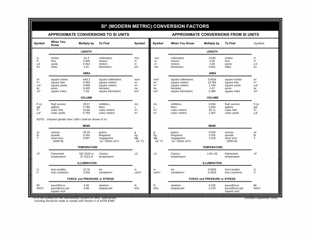
SI* (MODERN METRIC) CONVERSION FACTORS
APPROXIMATE CONVERSIONS TO SI UNITS APPROXIMATE CONVERSIONS FROM SI UNITS
Symbol When YouKnow
Multiply by To Find Symbol Symbol When You Know Multiply by To Find Symbol
LENGTH LENGTH
in f t y d mi
inchesfeetyardsmiles
25.40.3050.9141.61
millimetersmetersmeterskilometers
mmmmkm
mm m m km
millimetersmetersmeterskilometers
0.0393.281.090.621
inchesfeetyardsmiles
inf ty dmi
AREA AREA
in2
f t2
y d2
ac mi2
square inchessquare feetsquare yardsacressquare miles
square inchessquare feetsquare yardsacressquare miles
in2
f t2
y d2
acmi2
VOLUME VOLUME
fl oz gal f t3
y d3
fluid ouncesgallonscubic feetcubic yards
29.573.7850.0280.765
millilitersliterscubic meterscubic meters
mLLm3
m3
mL L m3
m3
millilitersliterscubic meterscubic meters
0.0340.26435.711.307
fluid ouncesgallonscubic feetcubic yards
fl ozgalf t3
y d3
NOTE: Volumes greater than 1000 l shall be shown in m3.
MASS MASS
oz lb T
ouncespoundsshort tons (2000 lb)
28.350.4540.907
gramskilogramsmegagrams (or “metric ton”)
gkgMg (or “t”)
g kg Mg (or “t”)
gramskilogramsmegagrams (or “metric ton”)
0.0352.2021.103
ouncespoundsshort tons (2000 lb)
ozlbT
TEMPERATURE TEMPERATURE
EF Fahrenheittemperature
5(F-32)/9 or(F-32)/1.8
Celciustemperature
EC EC Celciustemperature
1.8C+32 Fahrenheittemperature
EF
ILLUMINATION ILLUMINATION
f c f l
foot-candlesfoot-Lamberts
10.763.426
luxcandela/m2
lxcd/m2
lx cd/m2
luxcandela/m2
0.09290.2919
foot-candlesfoot-Lamberts
f cf l
FORCE and PRESSURE or STRESS FORCE and PRESSURE or STRESS
lbf lbf/in2
poundforcepoundforce persquare inch
4.456.89
newtonskilopascals
NkPa
N kPa
newtonskilopascals
0.2250.145
poundforcepoundforce persquare inch
lbflbf/in2
*SI is the symbol for the International System of Units. Appropriate (Revised September 1993) rounding should be made to comply with Section 4 of ASTM E380.
(accelerometer located at center of gravity) . . . . . . . . . . . . . . . . . . . . . . . . . . . . . . . . . . 2416 Vehicle lateral accelerometer traces for test 404211-5a
(accelerometer located at center of gravity) . . . . . . . . . . . . . . . . . . . . . . . . . . . . . . . . . . 2517 Vehicle vertical accelerometer trace for test 404211-5a
(accelerometer located at center of gravity) . . . . . . . . . . . . . . . . . . . . . . . . . . . . . . . . . . 2618 Vehicle longitudinal accelerometer trace for test 404211-5a
(accelerometer located in front section of the cab of the vehicle) . . . . . . . . . . . . . . . . . . 2719 Vehicle lateral accelerometer traces for test 404211-5a
(accelerometer located in front section of the cab of the vehicle) . . . . . . . . . . . . . . . . . . 2820 Vehicle longitudinal accelerometer trace for test 404211-5a
The Federal Highway Administration (FHWA) has recently adopted the new performanceevaluation guidelines for roadside safety features set forth in National Cooperative Highway ResearchProgram (NCHRP) Report 350.(1) In addition, FHWA has required that all new roadside safetyfeatures to be installed on the National Highway System (NHS) after September 1998 meet theNCHRP Report 350 performance evaluation guidelines. Most of the existing roadside safety featureswere tested according to the previous guidelines contained in NCHRP Report 230.(2) Testing existingroadside safety features to evaluate how they would perform under the new guidelines is, therefore,necessary.
The modified thrie beam guardrail has been successfully tested at Test Level 3 (TL-3) ofNCHRP Report 350.(3) FHWA decided that the guardrail should be tested to TL-4, which involves acrash test with the 8000S (single-unit truck) traveling at a nominal speed and angle of 80 km/h and 15degrees, impacting the critical impact point. This test is intended to evaluate the strength of the section incontaining and redirecting the heavy vehicle.
This report presents the details and results of NCHRP Report 350 test designation 4-12 forevaluation of the modified thrie beam to TL-4. The modified thrie beam guardrail met all requirementsfor NCHRP Report 350 test designation 4-12.
II. STUDY APPROACH
TEST ARTICLE
The modified thrie beam guardrail system consisted of 2.1-m-long W150x14 steel postsspaced 1.9 m apart with W360x33 blockouts. A cross-section of the modified thrie beam guardrailsystem is shown in figure 1. The blockouts were 432 mm long, 457 mm deep, and 152 mm wide at theflanges. The web of the blockout had a cutout measuring 152 mm at the bottom and angled upward at40 degrees to the flange upon which the thrie beam was attached. The blockout was attached to thepost with four 16-mm-diameter bolts and the thrie beam rail element was attached to the blockout witha single 16-mm-diameter button head bolt without a washer. The mounting height of the thrie beam railwas 610 mm to the center and 864 mm to the top of the thrie beam rail element.
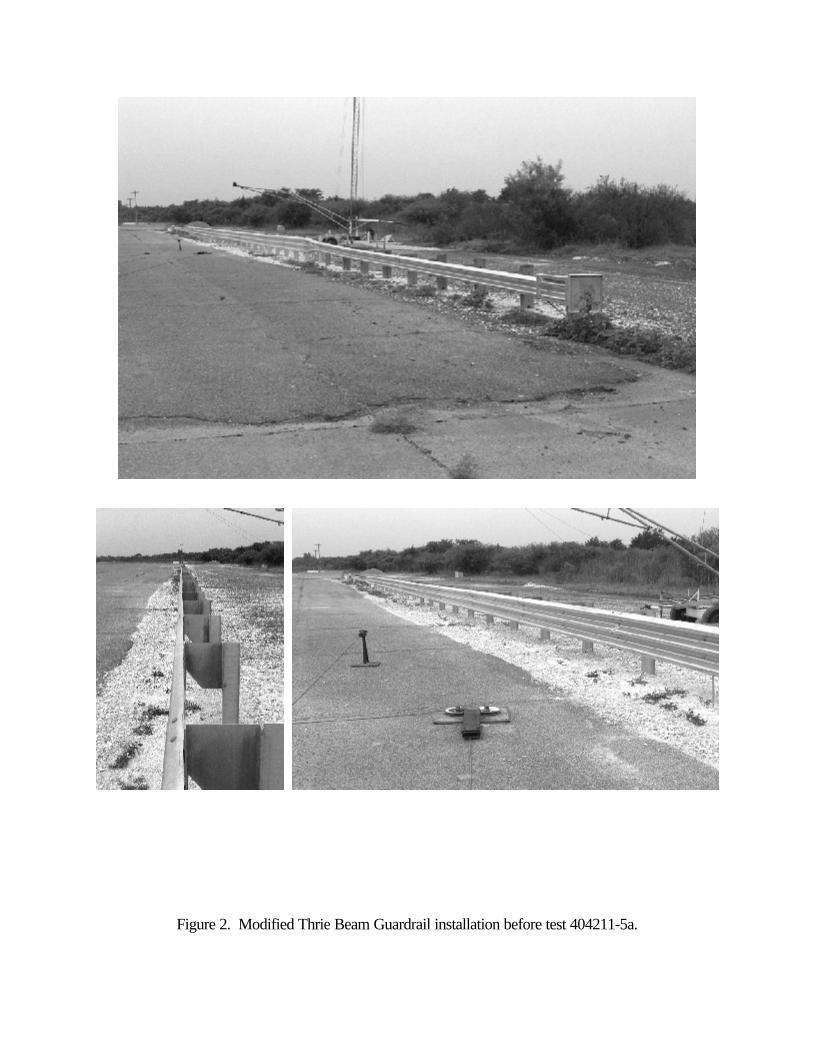
The test installation consisted of a 45.7-m-long length-of-need section of modified thrie-beamguardrail with a 1.9-m-long transition section from the thrie beam to the W-beam rail element, and a15.2-m-long ET-2000 at each end, for a total installation length of 80.0 m. The details and layout ofthe test installation are shown in figure 1. Photographs of the completed test installation are shown infigure 2.
CRASH TEST CONDITIONS
According to NCHRP Report 350, three crash tests are required for evaluation of longitudinalbarriers to Test Level four (TL-4):
NCHRP Report 350 test designation 4-10: An 820-kg passenger car impacting the criticalimpact point (CIP) in the length of need (LON) of the longitudinal barrier at a nominal speedand angle of 100 km/h and 20 degrees. The purpose of this test is to evaluate the overallperformance of the LON section in general, and occupant risks in particular.
NCHRP Report 350 test designation 4-11: A 2000-kg pickup truck impacting the CIP inthe LON of the longitudinal barrier at a nominal speed and angle of 100 km/h and 25 degrees.The test is intended to evaluate the strength of the section in containing and redirecting thepickup truck.
NCHRP Report 350 test designation 4-12: An 8000-kg single-unit truck impacting the CIPin the LON of the longitudinal barrier at a nominal speed and angle of 80 km/h and 15 degrees.The test is intended to evaluate the strength of the section in containing and redirecting theheavy truck.
Figure 1. Details of the Modified Thrie Beam Guardrail installation.
Figure 2. Modified Thrie Beam Guardrail installation before test 404211-5a.
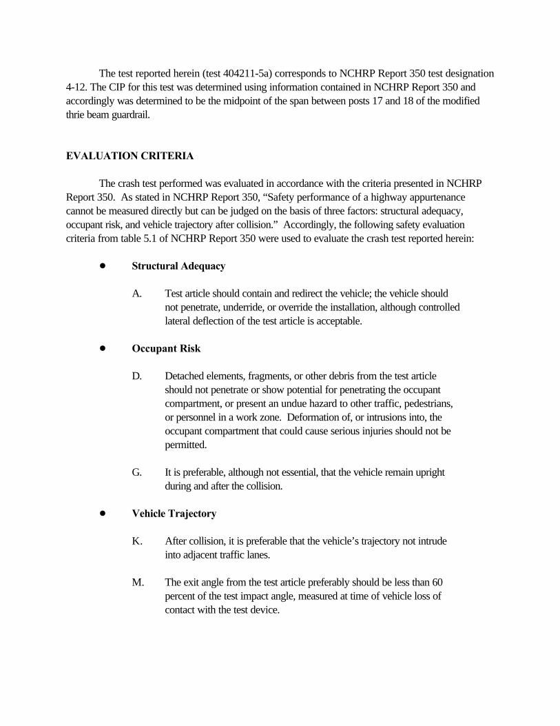
The test reported herein (test 404211-5a) corresponds to NCHRP Report 350 test designation4-12. The CIP for this test was determined using information contained in NCHRP Report 350 andaccordingly was determined to be the midpoint of the span between posts 17 and 18 of the modifiedthrie beam guardrail.
EVALUATION CRITERIA
The crash test performed was evaluated in accordance with the criteria presented in NCHRPReport 350. As stated in NCHRP Report 350, “Safety performance of a highway appurtenancecannot be measured directly but can be judged on the basis of three factors: structural adequacy,occupant risk, and vehicle trajectory after collision.” Accordingly, the following safety evaluationcriteria from table 5.1 of NCHRP Report 350 were used to evaluate the crash test reported herein:
! Structural Adequacy
A. Test article should contain and redirect the vehicle; the vehicle shouldnot penetrate, underride, or override the installation, although controlledlateral deflection of the test article is acceptable.
! Occupant Risk
D. Detached elements, fragments, or other debris from the test articleshould not penetrate or show potential for penetrating the occupantcompartment, or present an undue hazard to other traffic, pedestrians,or personnel in a work zone. Deformation of, or intrusions into, theoccupant compartment that could cause serious injuries should not bepermitted.
G. It is preferable, although not essential, that the vehicle remain uprightduring and after the collision.
! Vehicle Trajectory
K. After collision, it is preferable that the vehicle’s trajectory not intrudeinto adjacent traffic lanes.
M. The exit angle from the test article preferably should be less than 60percent of the test impact angle, measured at time of vehicle loss ofcontact with the test device.
CRASH TEST AND DATA ANALYSIS PROCEDURES
The crash test and data analysis procedures were in accordance with guidelines presented inNCHRP Report 350. Brief descriptions of these procedures are presented as follows.
Electronic Instrumentation and Data Processing
The test vehicle was instrumented with three solid-state angular rate transducers to measureroll, pitch, and yaw rates; a triaxial accelerometer near the vehicle center of gravity to measurelongitudinal, lateral, and vertical acceleration levels; a back-up biaxial accelerometer in the rear of thevehicle to measure longitudinal and lateral acceleration levels; and another back-up biaxialaccelerometer in the front of the cab of the vehicle to measure longitudinal and lateral accelerationlevels. The accelerometers were strain-gauge type with a linear millivolt output proportional toacceleration.
The electronic signals from the accelerometers and transducers were transmitted to a basestation by means of constant bandwidth FM/FM telemetry link for recording on magnetic tape and fordisplay on a real-time strip chart. Calibration signals were recorded before and after the test, and anaccurate time reference signal was simultaneously recorded with the data. Pressure-sensitive switcheson the bumper of the impacting vehicle were actuated just prior to impact by wooden dowels toindicate the elapsed time over a known distance to provide a measurement of impact velocity. Theinitial contact also produced an "event" mark on the data record to establish the exact instant of contactwith the installation.
The multiplex of data channels, transmitted on one radio frequency, was received at the dataacquisition station and demultiplexed into separate tracks of Inter-Range Instrumentation Group(I.R.I.G.) tape recorders. After the test, the data were played back from the tape machines, filteredwith an SAE J211 filter, and digitized using a microcomputer for analysis and evaluation of impactperformance.
The digitized data were then processed using two computer programs: DIGITIZE andPLOTANGLE. Brief descriptions of the functions of these two computer programs are provided asfollows:
The DIGITIZE program uses digitized data from vehicle-mounted linear accelerometers tocompute occupant/compartment impact velocities, time of occupant/compartment impact after vehicleimpact, and the highest 10-ms average ridedown acceleration. The DIGITIZE program also calculatesa vehicle impact velocity and the change in vehicle velocity at the end of a given impulse period. Inaddition, maximum average accelerations over 50-ms intervals in each of the three directions arecomputed. For reporting purposes, the data from the vehicle-mounted accelerometers were thenfiltered with a 60-Hz digital filter and acceleration versus time curves for the longitudinal, lateral, andvertical directions were plotted using a commercially available software package (Excel 97).
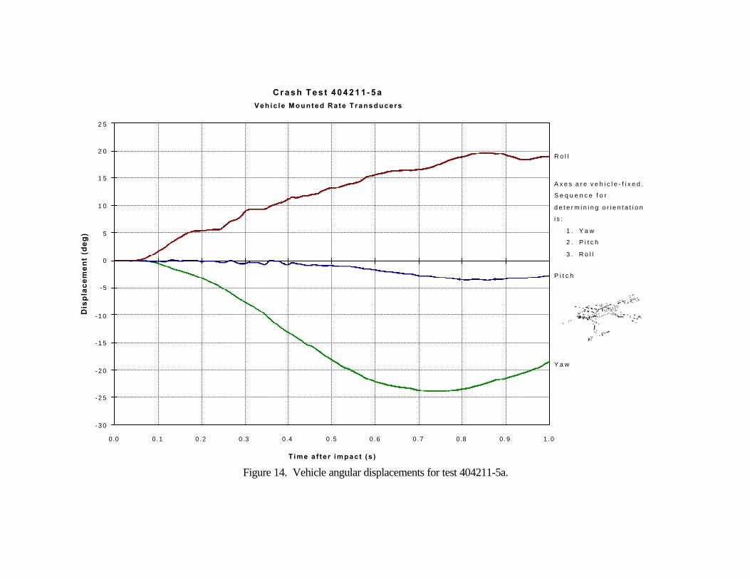
The PLOTANGLE program used the digitized data from the yaw, pitch, and roll ratetransducers to compute angular displacement in degrees at 0.00067-s intervals and then instructs aplotter to draw a reproducible plot: yaw, pitch, and roll versus time. These displacements are inreference to the vehicle-fixed coordinate system with the initial position and orientation of the vehicle-fixed coordinate system being that which existed at initial impact.
Anthropomorphic Dummy Instrumentation
Use of a dummy in the 8000S vehicle is optional according to NCHRP Report 350 and therewas no dummy used in the test with the 8000S vehicle.
Photographic Instrumentation and Data Processing
Photographic coverage of the test included three high-speed cameras: one overhead with a fieldof view perpendicular to the ground and directly over the impact point; one placed behind theinstallation at an angle; and a third placed to have a field of view parallel to and aligned with theinstallation at the downstream end. A flash bulb activated by pressure-sensitive tape switches waspositioned on the impacting vehicle to indicate the instant of contact with the installation and was visiblefrom each camera. The films from these high-speed cameras were analyzed on a computer-linkedMotion Analyzer to observe phenomena occurring during the collision and to obtain time-event,displacement, and angular data. A Betacam, a VHS-format video camera and recorder, and stillcameras were used to record and document the condition of the test vehicle and installation before andafter the test.
Test Vehicle Propulsion and Guidance
The test vehicle was towed into the test installation using a steel cable guidance and reverse towsystem. A steel cable for guiding the test vehicle was tensioned along the path, anchored at each end,and threaded through an attachment to the front wheel of the test vehicle. An additional steel cable wasconnected to the test vehicle, passed around a pulley near the impact point, through a pulley on the towvehicle, and then anchored to the ground such that the tow vehicle moved away from the test site. A 2-to-1 speed ratio between the test and tow vehicle existed with this system. Just prior to impact with theinstallation, the test vehicle was released to be free-wheeling and unrestrained. The vehicle remainedfree-wheeling, i.e., no steering or braking inputs, until the vehicle cleared the immediate area of the testsite, at which time brakes on the vehicle were activated to bring it to a safe and controlled stop.
III. CRASH TEST RESULTS
TEST 404211-5a (NCHRP Report 350 Test No. 4-12)
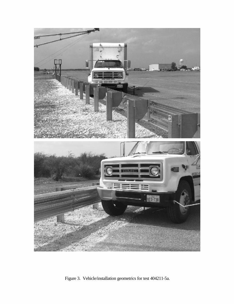
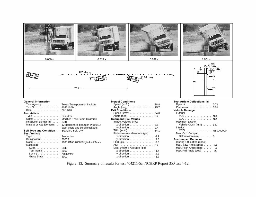
A 1988 GMC 7000 single-unit truck, shown in figures 3 and 4, was used for the crash test. Test inertia weight of the vehicle was 8000 kg, and its gross static weight was 8000 kg. The height tothe lower edge of the vehicle bumper was 520 mm and it was 815 mm to the upper edge of thebumper. Additional dimensions and information on the vehicle are given in figure 5. The vehicle wasdirected into the installation using the cable reverse tow and guidance system, and was released to befree-wheeling and unrestrained just prior to impact.
The test was performed the morning of June 12, 1998. Norain had occurred for the 10 days prior to the test. Moisture content atposts 18, 20, and 22 was 6.7%, 4.0%, and 5.1%, respectively.Weather conditions during the time of the test were as follows: WindSpeed: 16 km/h; Wind Direction: 345 degrees with respect to thevehicle (vehicle was traveling in a southwesterly direction); Temperature: 34EC; Relative Humidity: 51 percent.
Test Description
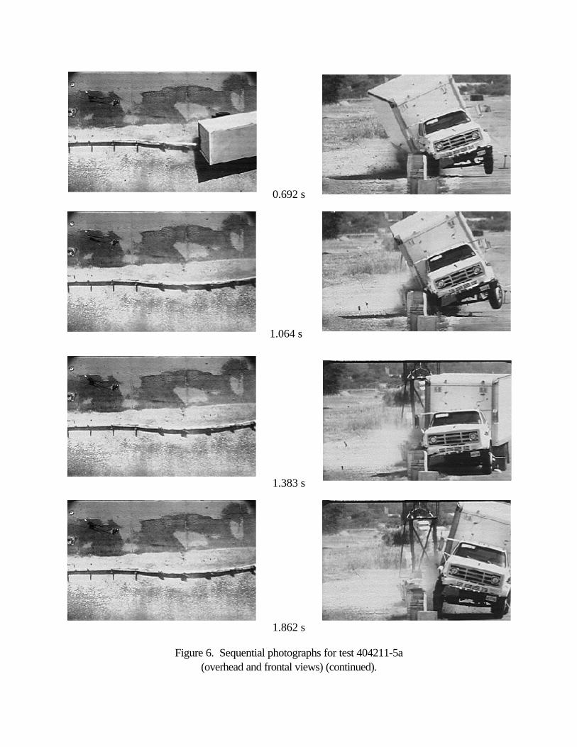
The vehicle, traveling at 78.8 km/h, impacted the modified thrie beam guardrail 750 mm beforepost 18 at an impact angle of 15.7 degrees. Shortly after impact, post 18 and then post 17 moved. By0.036 s after impact, the vehicle contacted post 18 and at 0.039 s, post 19 moved. The vehicle beganto redirect at 0.061 s and post 20 moved at 0.098 s. At 0.130 s, the vehicle contacted post 19 and at0.137 s, post 21 moved. Post 22 moved at 0.225 s and the vehicle contacted post 21 at 0.301 s. Post23 moved at 0.322 s, the right rear tire contacted the guardrail at 0.361 s, and the front of the vehiclecontacted post 22 at 0.397 s. The vehicle was traveling parallel with the guardrail at 0.416 s at a speedof 64.6 km/h. At 0.505 s, the front wheels turned to the right and the front of the vehicle lost contactwith the rail at 0.521 s. The rear of the vehicle lost contact with the guardrail near post 26 at 0.612 sand was traveling at 64.0 km/h and an exit angle of 8.2 degrees. The vehicle rotated clockwise at0.851 s and contacted the guardrail between posts 27 and 28 at 1.138 s. At 1.160 s, the front wheelsturned to the left and at 1.673 s, the vehicle lost contact with the guardrail just past post 30. The vehiclecontinued forward and then contacted the ET-2000 between posts 37 and 38 at 3.551 s. As thevehicle continued forward, the vehicle pulled the ET-2000 head off the end. The vehicle rode off theend of the terminal and brakes on the vehicle were applied at 4.9 s. The vehicle subsequently came torest 70.7 m down from impact and in line with the installation. Sequential photographs of the test periodare shown in figures 6 and 7.
Figure 3. Vehicle/installation geometrics for test 404211-5a.
Figure 4. Vehicle before test 404211-5a.
Figure 5. Vehicle properties for test 404211-5a.
0.000 s
0.319 s
0.479 s
Figure 6. Sequential photographs for test 404211-5a(overhead and frontal views).
0.106 s
0.692 s
1.383 s
1.862 s
Figure 6. Sequential photographs for test 404211-5a(overhead and frontal views) (continued).
1.064 s
0.000 s
0.319 s
0.479 s
Figure 7. Sequential photographs for test 404211-5a(rear view).
1.064 s
1.383 s
1.862 s
0.106 s
0.692 s
Damage to Test Installation
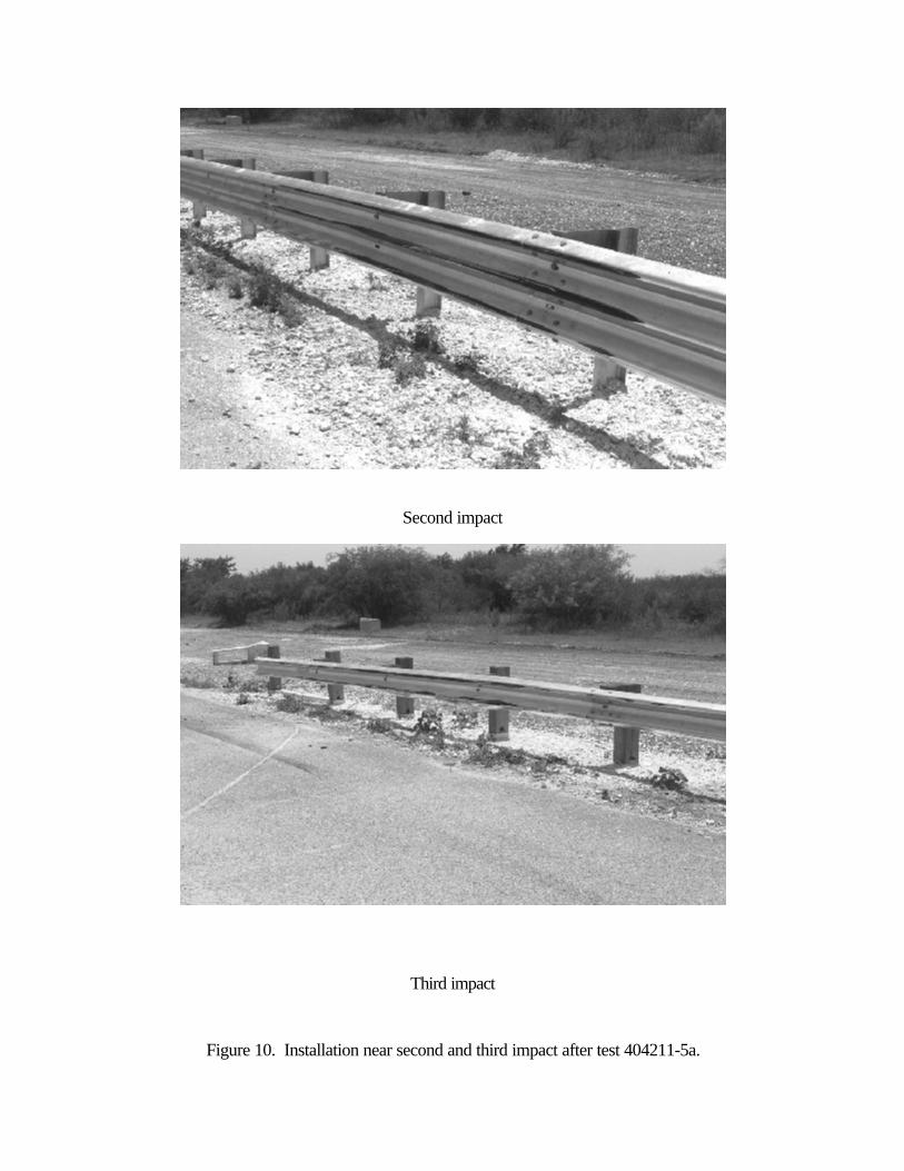
Damage to the modified thrie beam guardrail is shown in figures 8 and 9. Posts 19 through 26were deformed and the blockouts on those posts were significantly deformed. The blockouts on posts17, 18, and 27 were slightly deformed. The guardrail bolts pulled through the thrie beam at posts 20,23, 24, and 25. Tire marks were on the face of posts 20 and 21. Length of contact during the initialcollision was 16.0 m of which the truck rode on top of the thrie beam for 2.8 m. The second contactoccurred between posts 27 and 28 and continued to just past post 30. The third contact occurredbetween posts 37 and 38 and the vehicle rode off the end, taking the ET-2000 head off the end.Maximum dynamic deflection during the test was 0.71 m and maximum permanent deformation was0.51 m, both occurring near post 21.
Vehicle Damage
Minimal damage was sustained by the vehicle as shown in figure 10. Structural damage wasreceived by the front axle and right front wheel. The lower right front corner of the cargo box receiveda dent as well as the right side fuel tank. The bumper and supports, hood, right front quarter panel, grill,and right door step were damaged. The right door was jammed and the right outside tire receivedgouges. Maximum exterior vehicle crush was 140 mm at the right front corner of the bumper. Theinterior of the vehicle is shown in figure 11.
Occupant Risk Values
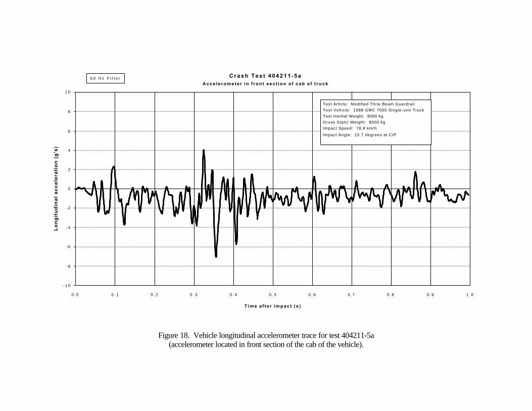
Occupant risk values are not required for this test, but were computed and are reported forinformation only. Data from the accelerometer located at the vehicle center of gravity were digitized andvalues are as follows: In the longitudinal direction, the occupant impact velocity was 3.5 m/s at 0.405 s,the highest 0.010-s occupant ridedown acceleration was -2.9 g’s from 0.394 to 0.404 s, and themaximum 0.050-s average acceleration was -1.4 g’s between 0.215 and 0.265 s. In the lateraldirection, the occupant impact velocity was -2.4 m/s at 0.301 s, the highest 0.010-s occupant ridedownacceleration was 3.8 g’s from 0.531 to 0.541 s, and the maximum 0.050-s average was 2.3 g’sbetween 0.699 and 0.749 s. These data and other pertinent information from the test are summarizedin figure 12. Vehicle angular displacements are displayed in figure 13. Vehicular accelerations versustime traces are presented in figures 14 through 20.
Figure 8. After-impact trajectory for test 404211-5a.
Figure 9. Installation near initial impactafter test 404211-5a.
Second impact
Third impact
Figure 10. Installation near second and third impact after test 404211-5a.
Figure 11. Vehicle after test 404211-5a.
Before test
After test
Figure 12. Interior of vehicle for test 404211-5a.
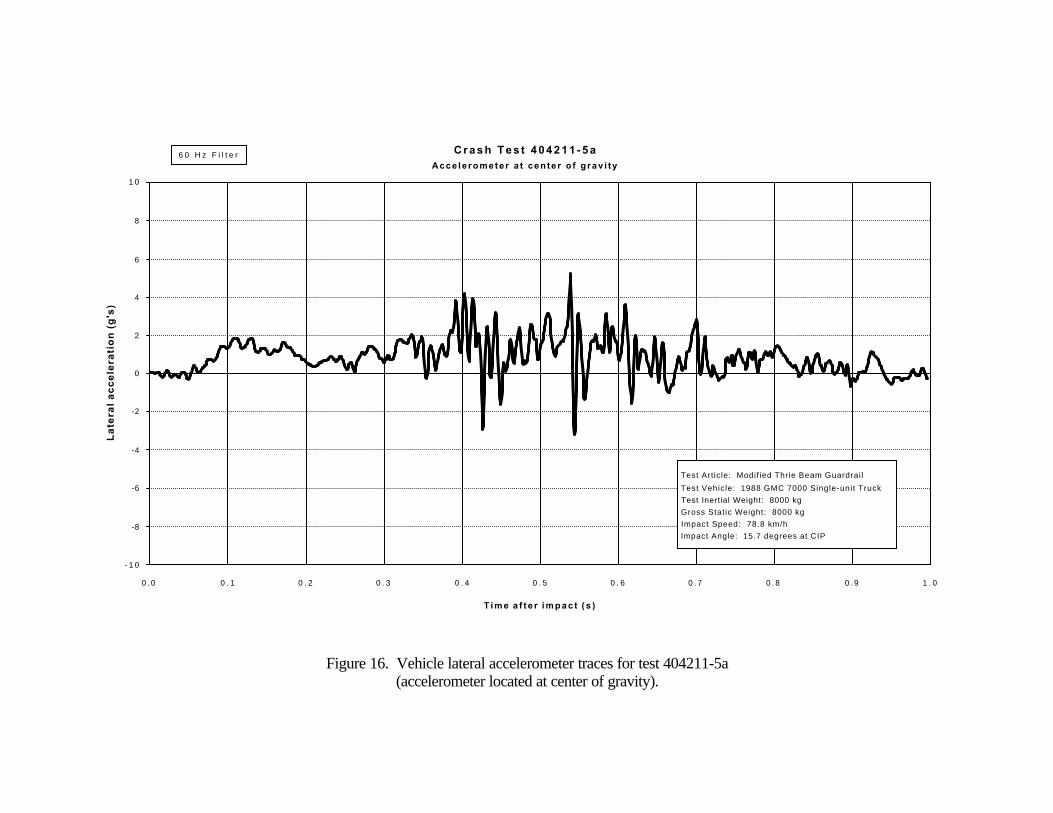
Test Article: Modified Thrie Beam Guardrail Test Vehicle: 1988 GMC 7000 Single-unit Truck Test Inertial Weight: 8000 kg Gross Static Weight: 8000 kg Impact Speed: 78.8 km/h Impact Angle: 15.7 degrees at CIP
Figure 16. Vehicle lateral accelerometer traces for test 404211-5a(accelerometer located at center of gravity).
C r a s h T e s t 4 0 4 2 1 1 - 5 aAcce le rometer a t cen te r o f g rav i ty
Test Article: Modif ied Thrie Beam Guardrail Test Vehicle: 1988 GMC 7000 Single-unit Truck Test Inertial Weight: 8000 kg Gross Static Weight: 8000 kg Impact Speed: 78.8 km/h Impact Angle: 15.7 degrees at CIP
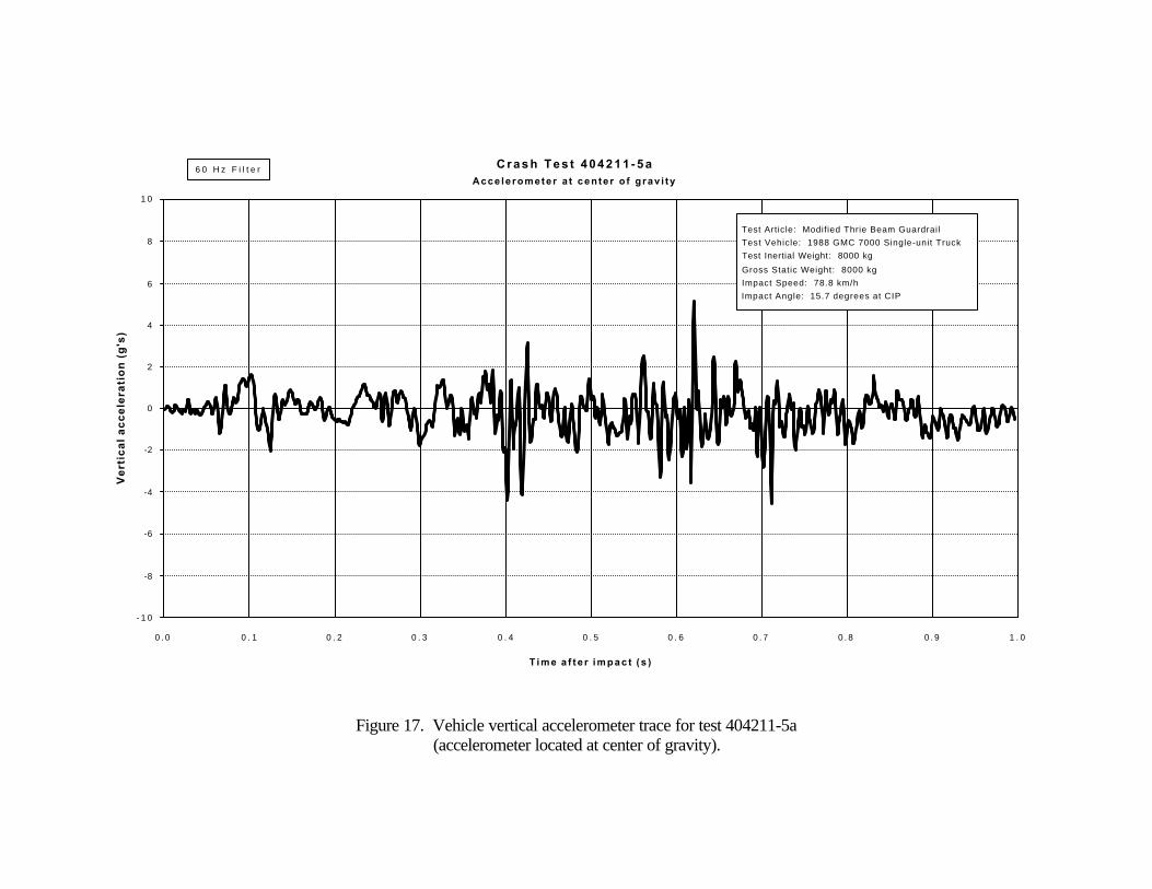
Figure 17. Vehicle vertical accelerometer trace for test 404211-5a(accelerometer located at center of gravity).
C r a s h T e s t 4 0 4 2 1 1 - 5 aAcce le rometer a t cen te r o f g rav i ty
Test Article: Modified Thrie Beam Guardrail Test Vehicle: 1988 GMC 7000 Single-unit Truck Test Inertial Weight: 8000 kg Gross Static Weight: 8000 kg Impact Speed: 78.8 km/h Impact Angle: 15.7 degrees at CIP
Figure 18. Vehicle longitudinal accelerometer trace for test 404211-5a(accelerometer located in front section of the cab of the vehicle).
C r a s h T e s t 4 0 4 2 1 1 - 5 aA c c e l e r o m e t e r i n f r o n t s e c t i o n o f c a b o f t r u c k
Test Article: Modified Thrie Beam Guardrail Test Vehicle: 1988 GMC 7000 Single-unit Truck Test Inertial Weight: 8000 kg Gross Static Weight: 8000 kg Impact Speed: 78.8 km/h Impact Angle: 15.7 degrees at CIP
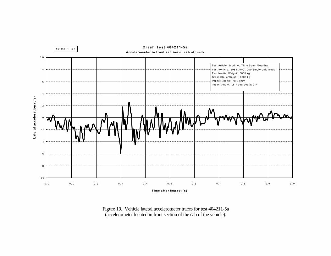
Figure 19. Vehicle lateral accelerometer traces for test 404211-5a(accelerometer located in front section of the cab of the vehicle).
C r a s h T e s t 4 0 4 2 1 1 - 5 aA c c e l e r o m e t e r i n f r o n t s e c t i o n o f c a b o f t r u c k
Test Article: Modif ied Thrie Beam Guardrail Test Vehicle: 1988 GMC 7000 Single-unit Truck Test Inertial Weight: 8000 kg Gross Static Weight: 8000 kg Impact Speed: 78.8 km/h Impact Angle: 15.7 degrees at CIP
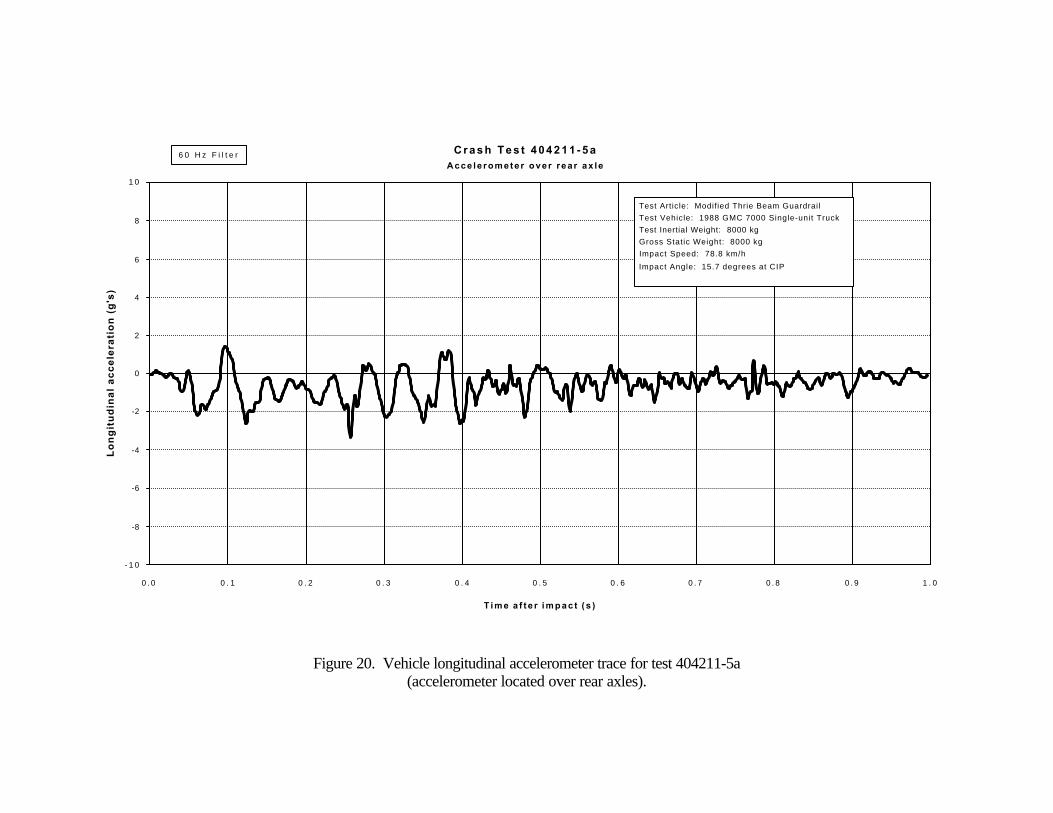
Figure 20. Vehicle longitudinal accelerometer trace for test 404211-5a(accelerometer located over rear axles).
C r a s h T e s t 4 0 4 2 1 1 - 5 aAcce le romete r over rea r ax le
Test Article: Modified Thrie Beam Guardrail Test Vehicle: 1988 GMC 7000 Single-unit Truck Test Inertial Weight: 8000 kg Gross Static Weight: 8000 kg Impact Speed: 78.8 km/h Impact Angle: 15.7 degrees at CIP
Figure 21. Vehicle lateral accelerometer traces for test 404211-5a(accelerometer located over rear axles).
C r a s h T e s t 4 0 4 2 1 1 - 5 aAcce le romete r over rea r ax le
Test Article: Modif ied Thrie Beam Guardrail Test Vehicle: 1988 GMC 7000 Single-unit Truck Test Inertial Weight: 8000 kg Gross Static Weight: 8000 kg Impact Speed: 78.8 km/h Impact Angle: 15.7 degrees at CIP
IV. SUMMARY OF FINDINGS AND CONCLUSIONS
SUMMARY OF FINDINGS
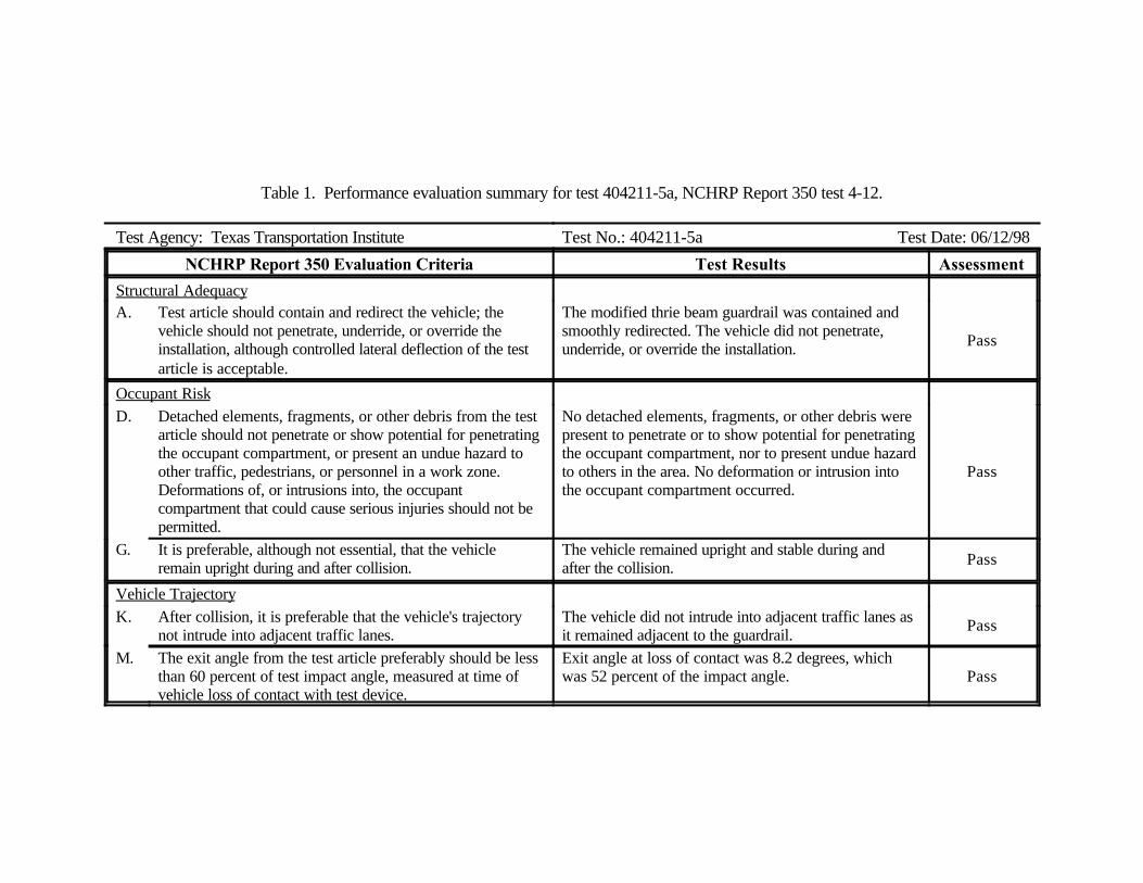
The modified thrie beam guardrail was contained and smoothly redirected. The vehicle did notpenetrate, underride, or override the installation. No detached elements, fragments, or other debriswere present to penetrate or to show potential for penetrating the occupant compartment, nor topresent undue hazard to others in the area. No deformation or intrusion into the occupant compartmentoccurred. The vehicle remained upright and stable during and after the collision. The vehicle did notintrude into adjacent traffic lanes as it remained adjacent to the guardrail. Exit angle at loss of contactwas 8.2 degrees, which was 52 percent of the impact angle.
CONCLUSIONS
As can be seen in table 4, the modified thrie beam guardrail met all requirements for NCHRPReport 350 test designation 4-12.
Table 1. Performance evaluation summary for test 404211-5a, NCHRP Report 350 test 4-12.
Test Agency: Texas Transportation Institute Test No.: 404211-5a Test Date: 06/12/98
NCHRP Report 350 Evaluation Criteria Test Results Assessment
Structural AdequacyA. Test article should contain and redirect the vehicle; the
vehicle should not penetrate, underride, or override theinstallation, although controlled lateral deflection of the testarticle is acceptable.
The modified thrie beam guardrail was contained andsmoothly redirected. The vehicle did not penetrate,underride, or override the installation. Pass
Occupant Risk
D. Detached elements, fragments, or other debris from the testarticle should not penetrate or show potential for penetratingthe occupant compartment, or present an undue hazard toother traffic, pedestrians, or personnel in a work zone. Deformations of, or intrusions into, the occupantcompartment that could cause serious injuries should not bepermitted.
No detached elements, fragments, or other debris werepresent to penetrate or to show potential for penetratingthe occupant compartment, nor to present undue hazardto others in the area. No deformation or intrusion intothe occupant compartment occurred.
Pass
G. It is preferable, although not essential, that the vehicleremain upright during and after collision.
The vehicle remained upright and stable during andafter the collision. Pass
Vehicle Trajectory
K. After collision, it is preferable that the vehicle's trajectorynot intrude into adjacent traffic lanes.
The vehicle did not intrude into adjacent traffic lanes asit remained adjacent to the guardrail.
Pass
M. The exit angle from the test article preferably should be lessthan 60 percent of test impact angle, measured at time ofvehicle loss of contact with test device.
Exit angle at loss of contact was 8.2 degrees, whichwas 52 percent of the impact angle. Pass
REFERENCES
1. H. E. Ross, Jr., D. L. Sicking, R. A. Zimmer, and J. D. Michie, Recommended Proceduresfor the Safety Performance Evaluation of Highway Features, NCHRP Report 350,Transportation Research Board, Washington, D.C., 1993.
2. J. D. Michie, Recommended Procedures for the Safety Performance Evaluation ofHighway Appurtenances, NCHRP Report 230, Transportation Research Board, Washington,D.C., 1980.
3. King K. Mak, Roger P. Bligh, and Wanda L. Menges, Testing of State Roadside SafetySystems, Volume I: Technical Report, Report FHWA-RD-98-036, prepared by TexasTransportation Institute, The Texas A&M University, College Station, Texas, for FederalHighway Administration, Washington, D.C., February 1998.