47
TRANSPORTATION RESEARCH BOARD Recommended Specifications for Large-Span Culverts NATIONAL COOPERATIVE HIGHWAY RESEARCH PROGRAM NCHRP REPORT 473 NATIONAL RESEARCH COUNCIL
| Date post: | 08-Apr-2018 |
| Category: |
Documents |
| Upload: | phungtuong |
| View: | 232 times |
| Download: | 9 times |

TRANSPORTATION RESEARCH BOARD
Recommended Specifications for
Large-Span Culverts
NATIONALCOOPERATIVE HIGHWAYRESEARCH PROGRAMNCHRP
REPORT 473
NATIONAL RESEARCH COUNCIL

TRANSPORTATION RESEARCH BOARD EXECUTIVE COMMITTEE 2002 (Membership as of January 2002)
OFFICERSChair: E. Dean Carlson, Secretary of Transportation, Kansas DOTVice Chair: Genevieve Giuliano, Professor, School of Policy, Planning, and Development, University of Southern California, Los AngelesExecutive Director: Robert E. Skinner, Jr., Transportation Research Board
MEMBERSWILLIAM D. ANKNER, Director, Rhode Island DOTTHOMAS F. BARRY, JR., Secretary of Transportation, Florida DOTMICHAEL W. BEHRENS, Executive Director, Texas DOTJACK E. BUFFINGTON, Associate Director and Research Professor, Mack-Blackwell National Rural Transportation Study Center,
University of ArkansasSARAH C. CAMPBELL, President, TransManagement, Inc., Washington, DCJOANNE F. CASEY, President, Intermodal Association of North AmericaJAMES C. CODELL III, Secretary, Kentucky Transportation CabinetJOHN L. CRAIG, Director, Nebraska Department of RoadsROBERT A. FROSCH, Senior Research Fellow, John F. Kennedy School of Government, Harvard UniversitySUSAN HANSON, Landry University Professor of Geography, Graduate School of Geography, Clark UniversityLESTER A. HOEL, L. A. Lacy Distinguished Professor, Department of Civil Engineering, University of VirginiaRONALD F. KIRBY, Director of Transportation Planning, Metropolitan Washington Council of GovernmentsH. THOMAS KORNEGAY, Executive Director, Port of Houston AuthorityBRADLEY L. MALLORY, Secretary of Transportation, Pennsylvania DOTMICHAEL D. MEYER, Professor, School of Civil and Environmental Engineering, Georgia Institute of TechnologyJEFF P. MORALES, Director of Transportation, California DOTDAVID PLAVIN, President, Airports Council International, Washington, DCJOHN REBENSDORF, Vice President, Network and Service Planning, Union Pacific Railroad Co., Omaha, NECATHERINE L. ROSS, Executive Director, Georgia Regional Transportation AgencyJOHN M. SAMUELS, Senior Vice President-Operations Planning & Support, Norfolk Southern Corporation, Norfolk, VAPAUL P. SKOUTELAS, CEO, Port Authority of Allegheny County, Pittsburgh, PAMICHAEL S. TOWNES, Executive Director, Transportation District Commission of Hampton Roads, Hampton, VAMARTIN WACHS, Director, Institute of Transportation Studies, University of California at BerkeleyMICHAEL W. WICKHAM, Chairman and CEO, Roadway Express, Inc., Akron, OHM. GORDON WOLMAN, Professor of Geography and Environmental Engineering, The Johns Hopkins University
MIKE ACOTT, President, National Asphalt Pavement Association (ex officio)JOSEPH M. CLAPP, Federal Motor Carrier Safety Administrator, U.S.DOT (ex officio)SUSAN M. COUGHLIN, Director and COO, The American Trucking Associations Foundation, Inc. (ex officio)JENNIFER L. DORN, Federal Transit Administrator, U.S.DOT (ex officio)ELLEN G. ENGLEMAN, Research and Special Programs Administrator, U.S.DOT (ex officio)ROBERT B. FLOWERS (Lt. Gen., U.S. Army), Chief of Engineers and Commander, U.S. Army Corps of Engineers (ex officio)HAROLD K. FORSEN, Foreign Secretary, National Academy of Engineering (ex officio)JANE F. GARVEY, Federal Aviation Administrator, U.S.DOT (ex officio)THOMAS J. GROSS, Deputy Assistant Secretary, Office of Transportation Technologies, U.S. Department of Energy (ex officio)EDWARD R. HAMBERGER, President and CEO, Association of American Railroads (ex officio)JOHN C. HORSLEY, Executive Director, American Association of State Highway and Transportation Officials (ex officio)MICHAEL P. JACKSON, Deputy Secretary of Transportation, U.S.DOT (ex officio)JAMES M. LOY (Adm., U.S. Coast Guard), Commandant, U.S. Coast Guard (ex officio)WILLIAM W. MILLAR, President, American Public Transportation Association (ex officio) MARGO T. OGE, Director, Office of Transportation and Air Quality, U.S. Environmental Protection Agency (ex officio)MARY E. PETERS, Federal Highway Administrator, U.S.DOT (ex officio)VALENTIN J. RIVA, President and CEO, American Concrete Pavement Association (ex officio)JEFFREY W. RUNGE, National Highway Traffic Safety Administrator, U.S.DOT (ex officio)JON A. RUTTER, Federal Railroad Administrator, U.S.DOT (ex officio)WILLIAM G. SCHUBERT, Maritime Administrator, U.S.DOT (ex officio)ASHISH K. SEN, Director, Bureau of Transportation Statistics, U.S.DOT (ex officio)ROBERT A. VENEZIA, Earth Sciences Applications Specialist, National Aeronautics and Space Administration (ex officio)
NATIONAL COOPERATIVE HIGHWAY RESEARCH PROGRAM
Transportation Research Board Executive Committee Subcommittee for NCHRPE. DEAN CARLSON, Kansas DOT (Chair)GENEVIEVE GIULIANO, University of Southern California,
Los AngelesLESTER A. HOEL, University of VirginiaJOHN C. HORSLEY, American Association of State Highway and
Transportation Officials
MARY E. PETERS, Federal Highway Administration
JOHN M. SAMUELS, Norfolk Southern Corporation, Norfolk, VA ROBERT E. SKINNER, JR., Transportation Research Board
T R A N S P O R T A T I O N R E S E A R C H B O A R D — N A T I O N A L R E S E A R C H C O U N C I L
NATIONAL ACADEMY PRESSWASHINGTON, D.C. — 2002
NATIONAL COOPERATIVE HIGHWAY RESEARCH PROGRAM
NCHRP REPORT 473
Research Sponsored by the American Association of State Highway and Transportation Officials in Cooperation with the Federal Highway Administration
SUBJECT AREAS
Bridges, Other Structures, and Hydraulics and Hydrology
Recommended Specifications for
Large-Span Culverts
T. J. MCGRATH
Simpson Gumpertz & Heger, Inc.
Arlington, MA
I. D. MOORE
Queens University
Kingston, Ontario, Canada
E. T. SELIG
Ernest T. Selig, Inc.
Hadley, MA
M. C. WEBB
Soil Structure Interaction Specialists
Pretoria, South Africa
B. TALEB
Acres International
Niagara Falls, Ontario, Canada
Published reports of the
NATIONAL COOPERATIVE HIGHWAY RESEARCH PROGRAM
are available from:
Transportation Research BoardNational Research Council2101 Constitution Avenue, N.W.Washington, D.C. 20418
and can be ordered through the Internet at:
http://www.trb.org/trb/bookstore
Printed in the United States of America
NATIONAL COOPERATIVE HIGHWAY RESEARCH PROGRAM
Systematic, well-designed research provides the most effectiveapproach to the solution of many problems facing highwayadministrators and engineers. Often, highway problems are of localinterest and can best be studied by highway departmentsindividually or in cooperation with their state universities andothers. However, the accelerating growth of highway transportationdevelops increasingly complex problems of wide interest tohighway authorities. These problems are best studied through acoordinated program of cooperative research.
In recognition of these needs, the highway administrators of theAmerican Association of State Highway and TransportationOfficials initiated in 1962 an objective national highway researchprogram employing modern scientific techniques. This program issupported on a continuing basis by funds from participatingmember states of the Association and it receives the full cooperationand support of the Federal Highway Administration, United StatesDepartment of Transportation.
The Transportation Research Board of the National ResearchCouncil was requested by the Association to administer the researchprogram because of the Board’s recognized objectivity andunderstanding of modern research practices. The Board is uniquelysuited for this purpose as it maintains an extensive committeestructure from which authorities on any highway transportationsubject may be drawn; it possesses avenues of communications andcooperation with federal, state and local governmental agencies,universities, and industry; its relationship to the National ResearchCouncil is an insurance of objectivity; it maintains a full-timeresearch correlation staff of specialists in highway transportationmatters to bring the findings of research directly to those who are ina position to use them.
The program is developed on the basis of research needsidentified by chief administrators of the highway and transportationdepartments and by committees of AASHTO. Each year, specificareas of research needs to be included in the program are proposedto the National Research Council and the Board by the AmericanAssociation of State Highway and Transportation Officials.Research projects to fulfill these needs are defined by the Board, andqualified research agencies are selected from those that havesubmitted proposals. Administration and surveillance of researchcontracts are the responsibilities of the National Research Counciland the Transportation Research Board.
The needs for highway research are many, and the NationalCooperative Highway Research Program can make significantcontributions to the solution of highway transportation problems ofmutual concern to many responsible groups. The program,however, is intended to complement rather than to substitute for orduplicate other highway research programs.
Note: The Transportation Research Board, the National Research Council,the Federal Highway Administration, the American Association of StateHighway and Transportation Officials, and the individual states participating inthe National Cooperative Highway Research Program do not endorse productsor manufacturers. Trade or manufacturers’ names appear herein solelybecause they are considered essential to the object of this report.
NCHRP REPORT 473
Project C12-45 FY’96
ISSN 0077-5614
ISBN 0-309-06757-X
Library of Congress Control Number 2002106859
© 2002 Transportation Research Board
Price $21.00
NOTICE
The project that is the subject of this report was a part of the National Cooperative
Highway Research Program conducted by the Transportation Research Board with the
approval of the Governing Board of the National Research Council. Such approval
reflects the Governing Board’s judgment that the program concerned is of national
importance and appropriate with respect to both the purposes and resources of the
National Research Council.
The members of the technical committee selected to monitor this project and to review
this report were chosen for recognized scholarly competence and with due
consideration for the balance of disciplines appropriate to the project. The opinions and
conclusions expressed or implied are those of the research agency that performed the
research, and, while they have been accepted as appropriate by the technical committee,
they are not necessarily those of the Transportation Research Board, the National
Research Council, the American Association of State Highway and Transportation
Officials, or the Federal Highway Administration, U.S. Department of Transportation.
Each report is reviewed and accepted for publication by the technical committee
according to procedures established and monitored by the Transportation Research
Board Executive Committee and the Governing Board of the National Research
Council.
FOREWORDBy David B. Beal
Staff OfficerTransportation Research
Board
This report contains the findings of a study to develop recommended design and con-struction specifications for metal and concrete large-span culverts. The report describesthe research effort leading to the recommended specifications and includes informationon field-testing and computer modeling. The methodology used to develop simplifieddesign equations is also included. The material in this report will be of immediate inter-est to specification writers and to engineers concerned with the design and constructionof large-span culverts.
Flexible and rigid large-span culverts, typically ranging from 3 to 9 m (10 to 30 ft),are often a practical structure for crossings, especially on local road systems. The useof these structures is growing, and the available design and construction specificationsrelated to them are in need of improvement. Large-span culverts are complex structureswhose design and performance are related to the interaction of the structure and the sur-rounding soil. Properties of the backfill envelope as well as in situ material have a majoreffect on the performance of these structures, and additional knowledge about theseeffects is needed.
Under NCHRP Project 12-45, Simpson Gumpertz & Heger, Inc., in cooperationwith the University of Massachusetts and the University of Western Ontario, monitoredthe performance of full-scale metal and concrete culverts during backfilling and undervehicle loads. The results of the experimental program were modeled and extended withfinite element analysis to create the data necessary to develop the simplified designexpressions. The analysis and compilation of prior experience with long-span culvertsprovided the basis for the recommended design and construction specifications for large-span culverts. These specifications are consistent in philosophy and format with theAASHTO LRFD Bridge Design Specifications and are accompanied by a commentary.

CONTENTS 1 SUMMARY
4 CHAPTER 1 INTRODUCTION AND RESEARCH APPROACH
5 CHAPTER 2 FINDINGSAssessment of Current Practice, 5
Soil Properties and Soil Behavior, 5Analysis, 7Design, 7Design Model for Metal Culverts, 8Design Model for Concrete Culverts, 10Construction of Large-Span Culverts, 10
Field Tests, 10Objectives, 10Test Plan, 10Results, 11
Analytical Modeling, 14Field Tests, 15Parametric Study of Metal Culvert Behavior, 20Parametric Study of Concrete Culvert Behavior, 24
Minimum Stiffness, 26Circumferential Stiffeners, 26Longitudinal Stiffeners, 26
Buckling, 27
28 CHAPTER 3 INTERPRETATION, APPRAISAL, AND APPLICATIONSimplified Design Methods, 28
Metal, 28Concrete, 31
Comprehensive Design Methods, 32Construction Specifications, 35
36 CHAPTER 4 CONCLUSIONS
38 REFERENCES
A-1 APPENDIX A Unpublished Material
B-1 APPENDIX B Full-Scale Field Tests
C-1 APPENDIX C Computer Modeling of Field Tests
D-1 APPENDIX D Development of Simplified Design Equations
E-1 APPENDIX E Comprehensive Design Method Guidelines
COOPERATIVE RESEARCH PROGRAMS STAFF FOR NCHRP REPORT 473
ROBERT J. REILLY, Director, Cooperative Research ProgramsCRAWFORD JENCKS, NCHRP ManagerDAVID B. BEAL, Senior Program OfficerEILEEN P. DELANEY, Managing EditorHILARY FREER, Associate Editor IIANDREA BRIERE, Associate Editor
NCHRP PROJECT 12-45 PANELField of Design—Area of Bridges
SUDHAKAR R. KULKARNI, Michigan DOT (Chair)NANCY McMULLIN BOBB, Federal Highway AdministrationRICHARD S. FOUNTAIN, Sandford, NCMICHAEL G. KATONA, Washington State UniversitySAMUEL C. MUSSER, Utah DOTGARY D. PETERSON, Minnesota DOTTHOMAS C. SANDFORD, University of MaineJOHN O’FALLON, FHWA Liaison RepresentativeDANIEL W. DEARASAUGH, JR., (Retired), TRB Liaison Representative
AUTHOR ACKNOWLEDGMENTSThis report was a collaborative effort of three research agencies:
Simpson Gumpertz & Heger, Inc.; the University of Massachusetts;and the University of Western Ontario. Successful completion of theproject required input and assistance from many more people otherthan the authors.
BEBO of America Inc. and Contech Construction Products Inc.donated the test structures and delivered them to the test site with-out cost to the project. Delta Materials Corp. provided a site for conducting the tests, also without cost to the project.
Prof. James LaFave, Jeanne Sussmann, Raymond Frenkel, DanielLovett, Troy Thiele, Brian Rowley, and Jun Wang made significantcontributions to the field tests.
Khaled El Sawy completed much of the pretest computer mod-eling.
Stephen DelloRusso and Daniel Valentine worked on instrumen-tation issues and evaluation of the simplified design methods.
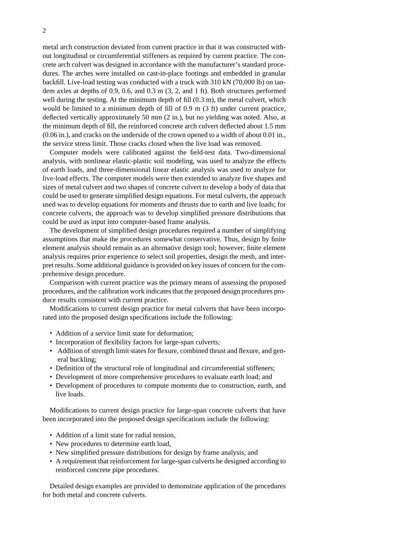
This project has completed a thorough review and evaluation of the state of the artin design and construction of large-span reinforced concrete and metal culverts, inves-tigated culvert behavior through full-scale field tests and extensive computer model-ing, and developed recommended specifications for design and construction.
This review indicates that current practice produces safe, reliable structures; however,much of the success is believed to result from experience, as current design proceduresare not specific and leave many important structural details unspecified. In particular,current procedures for metal culverts are largely empirical and do not address severalkey aspects of design, such as the role of stiffeners or the evaluation of moments thatdevelop during construction or in shallow-buried structures subject to live load. Currentpractice for concrete culverts is more defined than for metal culverts, but some key areasare still not addressed, such as the vertical load to be used in design. The review alsodemonstrated the importance of following correct construction procedures, as a numberof failures of large-span culverts have been attributed to poor control during construc-tion. There is a definite need for AASHTO to implement improved specifications.
The key focus of the project was to develop new design models for large-span cul-verts: (1) a simplified procedure that would accurately model most culvert installationsand be suitable for incorporation into AASHTO specifications, and (2) a comprehen-sive procedure that could be used for unusual installation or design conditions. Themethod used to develop these procedures was as follows:
• Full-scale field tests to develop data on culvert behavior during construction andunder shallow fills subject to live loads,
• Calibration of computer models with the field data,• Parametric studies of culvert behavior with calibrated computer models,• Development of simplified design equations based on parametric study results, and• Calibration and adjustment of the simplified design method through application of
the simplified design procedures for a range of culvert types and sizes.
The full-scale field tests evaluated the performance of a 9.5-m (31.2-ft) span metalarch culvert and a 9.1-m (30-ft) span precast, reinforced concrete arch culvert. The
SUMMARY
RECOMMENDED SPECIFICATIONS FOR LARGE-SPAN CULVERTS
metal arch construction deviated from current practice in that it was constructed with-out longitudinal or circumferential stiffeners as required by current practice. The con-crete arch culvert was designed in accordance with the manufacturer’s standard proce-dures. The arches were installed on cast-in-place footings and embedded in granularbackfill. Live-load testing was conducted with a truck with 310 kN (70,000 lb) on tan-dem axles at depths of 0.9, 0.6, and 0.3 m (3, 2, and 1 ft). Both structures performedwell during the testing. At the minimum depth of fill (0.3 m), the metal culvert, whichwould be limited to a minimum depth of fill of 0.9 m (3 ft) under current practice,deflected vertically approximately 50 mm (2 in.), but no yielding was noted. Also, atthe minimum depth of fill, the reinforced concrete arch culvert deflected about 1.5 mm(0.06 in.), and cracks on the underside of the crown opened to a width of about 0.01 in.,the service stress limit. Those cracks closed when the live load was removed.
Computer models were calibrated against the field-test data. Two-dimensionalanalysis, with nonlinear elastic-plastic soil modeling, was used to analyze the effectsof earth loads, and three-dimensional linear elastic analysis was used to analyze forlive-load effects. The computer models were then extended to analyze five shapes andsizes of metal culvert and two shapes of concrete culvert to develop a body of data thatcould be used to generate simplified design equations. For metal culverts, the approachused was to develop equations for moments and thrusts due to earth and live loads; forconcrete culverts, the approach was to develop simplified pressure distributions thatcould be used as input into computer-based frame analysis.
The development of simplified design procedures required a number of simplifyingassumptions that make the procedures somewhat conservative. Thus, design by finiteelement analysis should remain as an alternative design tool; however, finite elementanalysis requires prior experience to select soil properties, design the mesh, and inter-pret results. Some additional guidance is provided on key issues of concern for the com-prehensive design procedure.
Comparison with current practice was the primary means of assessing the proposedprocedures, and the calibration work indicates that the proposed design procedures pro-duce results consistent with current practice.
Modifications to current design practice for metal culverts that have been incorpo-rated into the proposed design specifications include the following:
• Addition of a service limit state for deformation;• Incorporation of flexibility factors for large-span culverts;• Addition of strength limit states for flexure, combined thrust and flexure, and gen-
eral buckling;• Definition of the structural role of longitudinal and circumferential stiffeners;• Development of more comprehensive procedures to evaluate earth load; and• Development of procedures to compute moments due to construction, earth, and
live loads.
Modifications to current design practice for large-span concrete culverts that havebeen incorporated into the proposed design specifications include the following:
• Addition of a limit state for radial tension,• New procedures to determine earth load,• New simplified pressure distributions for design by frame analysis, and• A requirement that reinforcement for large-span culverts be designed according to
reinforced concrete pipe procedures.
Detailed design examples are provided to demonstrate application of the proceduresfor both metal and concrete culverts.
2
The development of simplified procedures is not meant to prevent the use of moresophisticated methods of analysis, such as finite element analysis. The power of com-puter analysis by the finite element method is an important design tool; however, finiteelement analysis requires experience. Guidelines are provided for designers who wishto undertake culvert design by finite element analysis.
Construction specifications have also been developed. These specifications provideconsiderably more detail about the construction process than was previously availableto field personnel. New aspects of the construction specifications include the following:
• Limiting the use of backfills that consist of uniform fine sands;• Incorporating controlled, low-strength material as backfill;• Having detailed procedures for important steps in excavating and backfilling large-
span culverts;• Improving consistency across different types of culverts;• Improving terminology and definitions; and• Requiring post-construction inspection.
Overall, completion of this project represents a significant step forward for thedesign of large-span culverts. Designers and constructors will have greatly improvedtools available for designing and building these structures.
3
4
CHAPTER 1
INTRODUCTION AND RESEARCH APPROACH
Flexible and rigid large-span culverts, ranging in span from3 m (10 ft) to occasionally more than 15 m (50 ft), are oftena practical structure for short to intermediate span crossings,especially on local road systems. The use of these structures isgrowing; however, the available design and construction spec-ifications have not been updated for many years, and modifi-cations are needed to reflect current design theory and currentconstruction practices as well as to take advantage of increasedcomputational power for analysis.
Current design of metal culverts is largely experience based,and, with the exception of thrust, design forces are not com-puted. Also, stiffeners, called “special features,” are required,but no structural role is assigned to them. Overall, currentlarge-span metal culvert design lacks a suitable design model.Development of such a model is a particular need at this time,with AASHTO’s desire to incorporate load and resistance fac-tor design (LRFD) principles into the design of all bridgestructures. LRFD requires a suitable design model to properlyassess safety.
Current design of large-span concrete culverts is less empir-ical than that of metal culverts. However, several key param-
eters are still not defined, and the result is that designs mayvary because of reasonable interpretations of the code. Inparticular, the total vertical earth load is not specified, eventhough concrete culverts are known to carry more soil loadthan just the weight of earth above them.
Current construction specifications for metal and concreteculverts also do not reflect current knowledge. Because large-span culverts depend on soil support for proper performance,it is imperative that the construction procedures be carefullyspecified and implemented.
This project addresses these issues through a review of cur-rent practice, full-scale field tests to address key issues, andcomputer modeling to extend the results of the field tests.Based on the results of these tasks, recommended specifica-tions for design and construction of large-span metal and con-crete culverts have been developed. The design methods inthese specifications are simplified; they are suitable for incor-poration into AASHTO specifications. A protocol for com-prehensive analysis and design of large-span culverts by finiteelement analysis is also developed and presented.
5
ASSESSMENT OF CURRENT PRACTICE
Current practice for the design of large-span culverts issummarized in Appendix A of the research team’s finalreport. Key findings related to current practice and potentialimprovements are summarized in this chapter. A key conclu-sion of the review and evaluation is that there are a number ofdeficiencies in current practice; however, that should not beconstrued to mean that current practice is producing unsafedesigns. Instead, it means that current designs are basedlargely on experience, particularly in the case of large-spanmetal culverts. The empirical approach does not allow properconsideration of reliability, nor does it allow extension intolarger culvert spans or new culvert shapes. Thus, there is aneed to develop generalized design models.
Soil Properties and Soil Behavior
Large-span culverts are buried structures. Interactions ofculverts with the soil in which they are embedded affect theloads, moments, thrusts, and shear forces that the culvertmust carry to provide good service performance. Thus, properconsideration of the embedment is an important designconsideration.
A significant general concern with current AASHTO spec-ifications is that backfill is not considered part of the structuralsystem. Lateral pressures on culverts are considered part of theload, but in fact these pressures form part of the resistance thathelps culverts carry vertical earth loads. Also, it is difficult todetermine whether the bedding reaction under a closed culvert(e.g., circle, ellipse, or pear shape) is a load or a resistance.Although the bedding reaction is a function of the applied ver-tical loads, its magnitude and distribution are determined bydesign decisions. See, for example, the standard installation,direct design (SIDD) design method used for concrete pipe(AASHTO 1998), in which the designer selects the pressuredistribution, and this decision dictates both the loads and muchof the structural response. For buried culverts, it is probablybest to think of the soil-culvert combination as forming thestructural system. Designers must make decisions about typeand density of backfill as well as culvert parameters to com-plete designs. Thus, it is important to have soil and backfillinformation in the design specifications.
Once it is accepted that the soil embedment is a part of thestructural system, the designer must be aware of other deci-
sions that affect culvert performance. The width and stiffnessof the structural embedment at the side of the culvert is a keyparameter, yet current AASHTO specifications provide noguidance on the width of structural backfill. If the structuralbackfill is narrow, the stiffness of the soil beyond the structuralembedment will also affect structural performance. AmericanWater Works Association (AWWA) Manual M45 FiberglassPipe Design (AWWA 1995) provides a simple method fordetermining an effective composite soil modulus based on thestiffness of both the structural backfill and the surroundingembankment material as well as the width of the structuralbackfill. This project has also addressed the issue, as it affectsvertical loads on culverts. See below and Appendix C for fur-ther evaluation.
Soil Properties
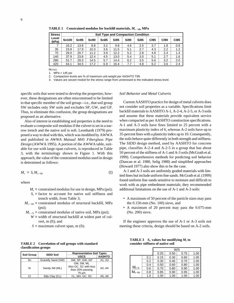
Since the start of this project, AASHTO has adopted pro-visions to improve design methods for thermoplastic cul-verts, including a new set of soil moduli to characterize soilstiffness for design. The values of the soil modulus weredeveloped by McGrath et al. (1999; see also McGrath 1998)based on hyperbolic soil parameters developed by Selig(1988) during development of the AASHTO SIDD designmethod for concrete pipe. The design parameter proposedby McGrath is the constrained (one-dimensional) modulus,which McGrath suggests can be treated as equal to the tra-ditional, but empirical, modulus of soil reaction E′. The con-strained modulus values (Table 1) display an increase in soilstiffness with increasing depth of fill, a well-documentedbehavior of soil in confined conditions. The design valuesfor Sn and Si soils in Table 1 are considered appropriate forthe design of large-span culverts. Properties for Cl soils areincluded in the table for reference purposes only, as Cl soilsare not considered acceptable backfill for large-span cul-verts. The table uses a two-letter, two-digit system to groupsoils. The letter designations are described and correlatedwith AASHTO and Unified Soil Classification System(USCS) soil classifications in Table 2. The two-number des-ignation indicates the soil unit weight as a percent of maxi-mum per the standard Proctor test (AASHTO T99).
Table 2 lists the SIDD soil group names as well as the sug-gested group names from Table 1. The SIDD groups arenamed for the USCS (ASTM D2487) classification of the
CHAPTER 2
FINDINGS
Soil Type and Compaction Condition Stress Level (kPa) Sn100 Sn95 Sn90 Sn85 Si95 Si90 Si85 Cl95 Cl90 Cl85
7 16.2 13.8 8.8 3.2 9.8 4.6 2.5 3.7 1.8 0.935 23.8 17.9 10.3 3.6 11.5 5.1 2.7 4.3 2.2 1.270 29.0 20.7 11.2 3.9 12.2 5.2 2.8 4.8 2.4 1.4
140 37.9 23.8 12.4 4.5 13.0 5.4 3.0 5.1 2.7 1.6280 51.7 29.3 14.5 5.7 14.4 6.2 3.5 5.6 3.2 2.0420 64.1 34.5 17.2 6.9 16.4 7.7 4.8 6.2 3.6 2.4
NOTES: 1. MPa = 145 psi 2. Compaction levels are % of maximum unit weight per AASHTO T99.3. Values are secant moduli for the stress range from unstressed to the indicated stress level.
W/S 0.25 0.50 0.75 1.00
0.1 0.15 0.30 0.60 1.000.2 0.30 0.45 0.70 1.000.4 0.50 0.60 0.80 1.000.6 0.70 0.80 0.90 1.000.8 0.85 0.90 0.95 1.00M
MSBs
Ns
−
−
1.0 1.00 1.00 1.00 1.00
Representative Soil Types Soil Group SIDD Soil USCS
Sn Gravelly Sand (SW) SW, SP, GW, GP A1, A3
Si Sandy Silt (ML)
GM, SM, ML Also GC, SC with less
than 20% passing 75 µm
A2, A4
Cl Silty Clay (CL) CL, MH, GC, SC A5, A6
AASHTO
6
specific soils that were tested to develop the properties; how-ever, these designations are often misconstrued to be limitedto that specific member of the soil group—i.e., that soil groupSW includes only SW soils and excludes SP, GW, and GP.Thus, to eliminate this confusion, the group designations areproposed as an alternative.
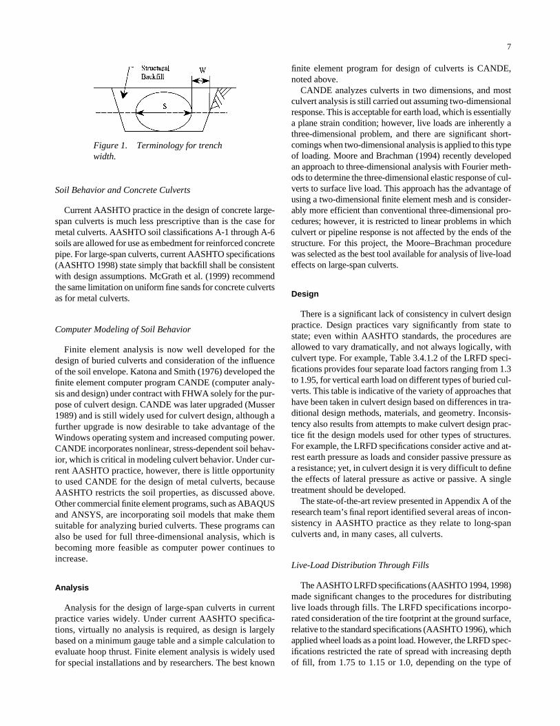
Also of interest in establishing soil properties is the need toevaluate a composite soil modulus if the culvert is set in a nar-row trench and the native soil is soft. Leonhardt (1979) pro-posed a way to deal with this, which was modified by AWWAand published in AWWA Manual M45 Fiberglass PipeDesign (AWWA 1995). A portion of the AWWA table, suit-able for use with large-span culverts, is reproduced in Table3, with the terminology shown in Figure 1. With thisapproach, the value of the constrained modulus used in designis determined as follows:
where
Ms = constrained modulus for use in design, MPa (psi);Sc = factor to account for native soil stiffness and
trench width, from Table 3;Ms − SB = constrained modulus of structural backfill, MPa
(psi);Ms − N = constrained modulus of native soil, MPa (psi);
W = width of structural backfill at widest part of cul-vert, m (ft); and
S = maximum culvert span, m (ft).
M S Ms c s SB= ( )− 1
Soil Behavior and Metal Culverts
Current AASHTO practice for design of metal culverts doesnot consider soil properties as a variable. Specifications limitbackfill materials to AASHTO A-1, A-2-4, A-2-5, or A-3 soilsand assume that these materials provide equivalent servicewhen compacted as per AASHTO construction specifications.A-1 and A-3 soils have fines limited to 25 percent with amaximum plasticity index of 6, whereas A-2 soils have up to35-percent fines with a plasticity index up to 10. Consequently,the soils behave quite differently in both strength and stiffness.The SIDD design method, used by AASHTO for concretepipe, classifies A-2-4 and A-2-5 in a group that has about50 percent of the stiffness of A-1 and A-3 soils (McGrath et al.1999). Comprehensive methods for predicting soil behavior(Duncan et al. 1980, Selig 1988) and simplified approaches(Howard 1977) also show this to be the case.
A-1 and A-3 soils are uniformly graded materials with lim-ited fines but include uniform fine sands. McGrath et al. (1999)found uniform fine sands sensitive to moisture and difficult towork with as pipe embedment materials; they recommendedadditional limitations on the use of A-1 and A-3 soils:
• A maximum of 50 percent of the particle sizes may passthe 0.150-mm (No. 100) sieve, and
• A maximum of 20 percent may pass the 0.075-mm (No. 200) sieve.
If the engineer approves the use of A-1 or A-3 soils notmeeting these criteria, design should be based on A-2 soils.
TABLE 1 Constrained modulus for backfill materials, Ms − SB, MPa
TABLE 2 Correlation of soil groups with standardclassification groups
TABLE 3 SC values for modifying Ms toconsider stiffness of native soil
7
finite element program for design of culverts is CANDE,noted above.
CANDE analyzes culverts in two dimensions, and mostculvert analysis is still carried out assuming two-dimensionalresponse. This is acceptable for earth load, which is essentiallya plane strain condition; however, live loads are inherently athree-dimensional problem, and there are significant short-comings when two-dimensional analysis is applied to this typeof loading. Moore and Brachman (1994) recently developedan approach to three-dimensional analysis with Fourier meth-ods to determine the three-dimensional elastic response of cul-verts to surface live load. This approach has the advantage ofusing a two-dimensional finite element mesh and is consider-ably more efficient than conventional three-dimensional pro-cedures; however, it is restricted to linear problems in whichculvert or pipeline response is not affected by the ends of thestructure. For this project, the Moore–Brachman procedurewas selected as the best tool available for analysis of live-loadeffects on large-span culverts.
Design
There is a significant lack of consistency in culvert designpractice. Design practices vary significantly from state tostate; even within AASHTO standards, the procedures areallowed to vary dramatically, and not always logically, withculvert type. For example, Table 3.4.1.2 of the LRFD speci-fications provides four separate load factors ranging from 1.3to 1.95, for vertical earth load on different types of buried cul-verts. This table is indicative of the variety of approaches thathave been taken in culvert design based on differences in tra-ditional design methods, materials, and geometry. Inconsis-tency also results from attempts to make culvert design prac-tice fit the design models used for other types of structures.For example, the LRFD specifications consider active and at-rest earth pressure as loads and consider passive pressure asa resistance; yet, in culvert design it is very difficult to definethe effects of lateral pressure as active or passive. A singletreatment should be developed.
The state-of-the-art review presented in Appendix A of theresearch team’s final report identified several areas of incon-sistency in AASHTO practice as they relate to long-spanculverts and, in many cases, all culverts.
Live-Load Distribution Through Fills
The AASHTO LRFD specifications (AASHTO 1994, 1998)made significant changes to the procedures for distributinglive loads through fills. The LRFD specifications incorpo-rated consideration of the tire footprint at the ground surface,relative to the standard specifications (AASHTO 1996), whichapplied wheel loads as a point load. However, the LRFD spec-ifications restricted the rate of spread with increasing depthof fill, from 1.75 to 1.15 or 1.0, depending on the type of
Soil Behavior and Concrete Culverts
Current AASHTO practice in the design of concrete large-span culverts is much less prescriptive than is the case formetal culverts. AASHTO soil classifications A-1 through A-6soils are allowed for use as embedment for reinforced concretepipe. For large-span culverts, current AASHTO specifications(AASHTO 1998) state simply that backfill shall be consistentwith design assumptions. McGrath et al. (1999) recommendthe same limitation on uniform fine sands for concrete culvertsas for metal culverts.
Computer Modeling of Soil Behavior
Finite element analysis is now well developed for thedesign of buried culverts and consideration of the influenceof the soil envelope. Katona and Smith (1976) developed thefinite element computer program CANDE (computer analy-sis and design) under contract with FHWA solely for the pur-pose of culvert design. CANDE was later upgraded (Musser1989) and is still widely used for culvert design, although afurther upgrade is now desirable to take advantage of theWindows operating system and increased computing power.CANDE incorporates nonlinear, stress-dependent soil behav-ior, which is critical in modeling culvert behavior. Under cur-rent AASHTO practice, however, there is little opportunityto used CANDE for the design of metal culverts, becauseAASHTO restricts the soil properties, as discussed above.Other commercial finite element programs, such as ABAQUSand ANSYS, are incorporating soil models that make themsuitable for analyzing buried culverts. These programs canalso be used for full three-dimensional analysis, which isbecoming more feasible as computer power continues toincrease.
Analysis
Analysis for the design of large-span culverts in currentpractice varies widely. Under current AASHTO specifica-tions, virtually no analysis is required, as design is largelybased on a minimum gauge table and a simple calculation toevaluate hoop thrust. Finite element analysis is widely usedfor special installations and by researchers. The best known
Figure 1. Terminology for trenchwidth.
backfill. The LRFD specifications considered the distribu-tion of loads through fills without considering the effect ofthe structure. Test results produced as part of this project aswell as prior research indicate that live loads spread over amuch greater area of structure than allowed by the LRFDspecification.
The reason for this difference varies with metal and con-crete culverts. Metal culverts deform under live load. Thisdeformation causes the development of shear stresses in thesoil that cause the live-load effect to spread out through the soiland over a larger area and mobilize a greater length of culvertto resist the loads. In concrete culverts, which are rigid, thereaction is somewhat different. The concrete culvert does notdeform significantly under load; however, concrete culvertsare so stiff that they internally spread the load over a greaterlength of structure than indicated by the LRFD specifications.
Earth Loads in General
Treatment of earth loads on large-span culverts is also vari-able in current AASHTO specifications. A trend in recentAASHTO specifications has been to specify loads in terms ofthe vertical arching factor, which relates the load on the pipein terms of the soil prism load. The soil prism load is theweight of soil directly over the culvert:
where
Wsp = soil prism load, kN/m [kips/in. (k/in.)];H = depth of fill over top of culvert, m (in.);γs = unit weight of soil, kN/m3 (k/in.3);
KVAF = factor to account for span/rise ratio;= 0.21 for circular culverts;= 0.172 + 0.019 (S/Ru) for other shapes;
S = culvert span, m (in.); andRu = upper rise, distance from widest point of culvert to
top of culvert, m (in.).
The load on the culvert is then determined as
where
WE = earth load on culvert, which is defined as totalspringline thrust (sum of thrust at both springlines),kN/m (k/in.); and
VAF = vertical arching factor to account for soil–culvertinteraction effects.
AASHTO has already adopted Equation 3 for concrete(VAF ∼ 1.4) and thermoplastic pipe (VAF varies from about0.25 to 1.0). The same approach is recommended for large-span culverts.
W WE spVAF= ( )3
W H K R Ssp s VAF u= +( ) ( )γ 2
8
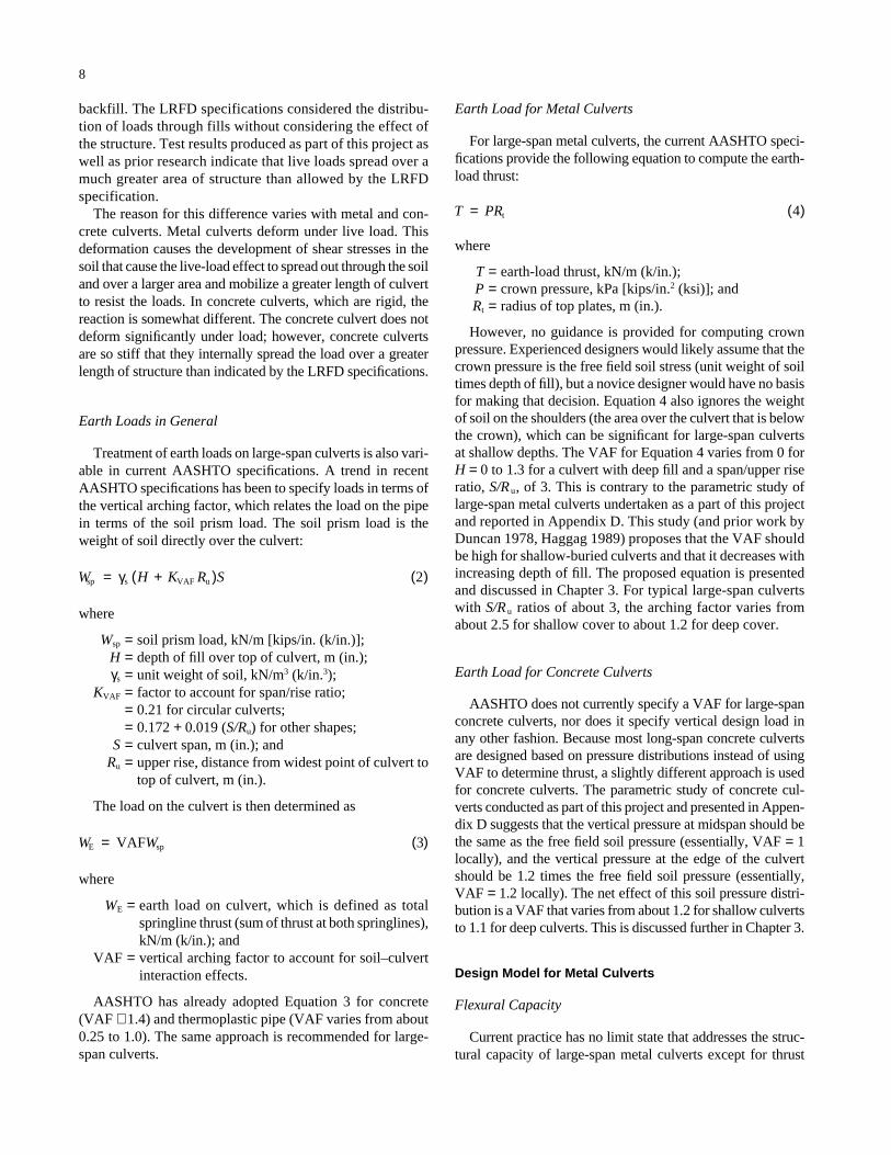
Earth Load for Metal Culverts
For large-span metal culverts, the current AASHTO speci-fications provide the following equation to compute the earth-load thrust:
where
T = earth-load thrust, kN/m (k/in.);P = crown pressure, kPa [kips/in.2 (ksi)]; andRt = radius of top plates, m (in.).
However, no guidance is provided for computing crownpressure. Experienced designers would likely assume that thecrown pressure is the free field soil stress (unit weight of soiltimes depth of fill), but a novice designer would have no basisfor making that decision. Equation 4 also ignores the weightof soil on the shoulders (the area over the culvert that is belowthe crown), which can be significant for large-span culverts at shallow depths. The VAF for Equation 4 varies from 0 forH = 0 to 1.3 for a culvert with deep fill and a span/upper riseratio, S/R u, of 3. This is contrary to the parametric study oflarge-span metal culverts undertaken as a part of this projectand reported in Appendix D. This study (and prior work byDuncan 1978, Haggag 1989) proposes that the VAF shouldbe high for shallow-buried culverts and that it decreases withincreasing depth of fill. The proposed equation is presentedand discussed in Chapter 3. For typical large-span culvertswith S/R u ratios of about 3, the arching factor varies fromabout 2.5 for shallow cover to about 1.2 for deep cover.
Earth Load for Concrete Culverts
AASHTO does not currently specify a VAF for large-spanconcrete culverts, nor does it specify vertical design load inany other fashion. Because most long-span concrete culvertsare designed based on pressure distributions instead of usingVAF to determine thrust, a slightly different approach is usedfor concrete culverts. The parametric study of concrete cul-verts conducted as part of this project and presented in Appen-dix D suggests that the vertical pressure at midspan should bethe same as the free field soil pressure (essentially, VAF = 1locally), and the vertical pressure at the edge of the culvertshould be 1.2 times the free field soil pressure (essentially,VAF = 1.2 locally). The net effect of this soil pressure distri-bution is a VAF that varies from about 1.2 for shallow culvertsto 1.1 for deep culverts. This is discussed further in Chapter 3.
Design Model for Metal Culverts
Flexural Capacity
Current practice has no limit state that addresses the struc-tural capacity of large-span metal culverts except for thrust
T PR= ( )t 4
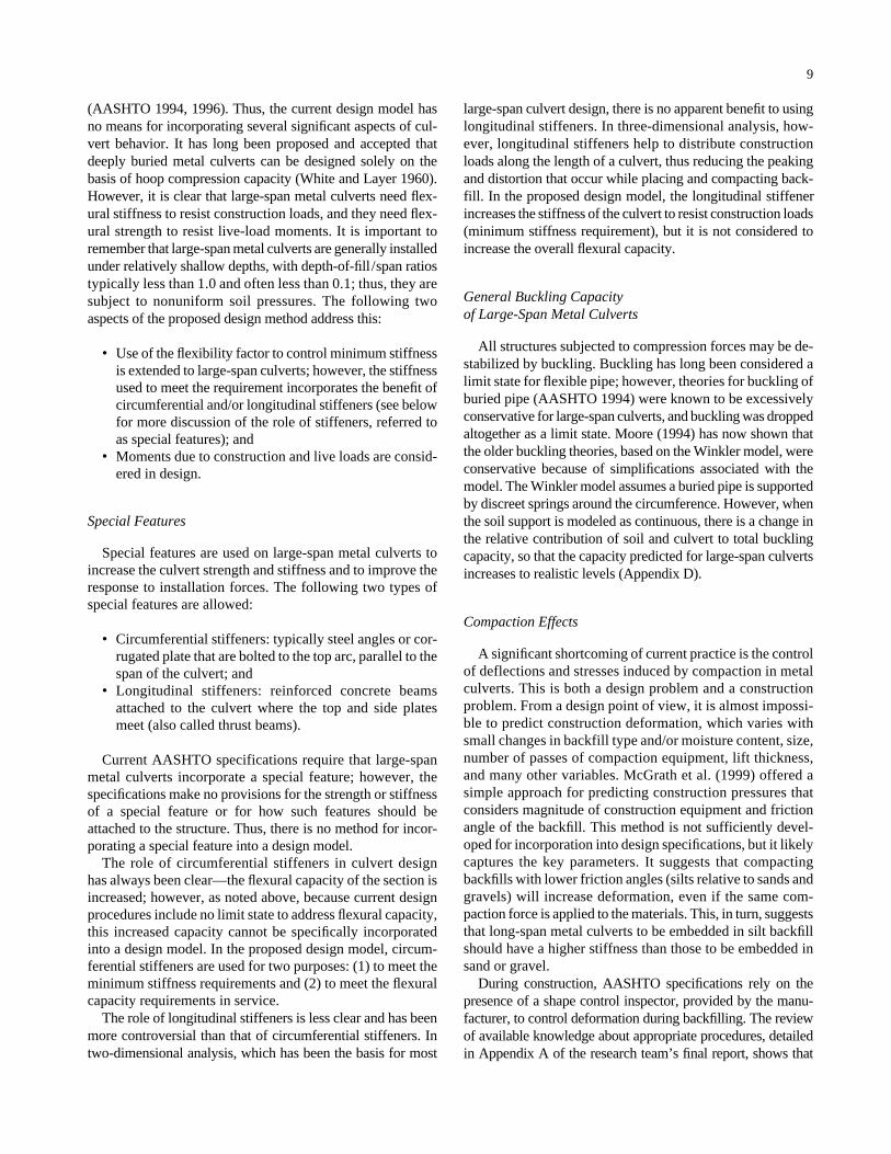
(AASHTO 1994, 1996). Thus, the current design model hasno means for incorporating several significant aspects of cul-vert behavior. It has long been proposed and accepted thatdeeply buried metal culverts can be designed solely on thebasis of hoop compression capacity (White and Layer 1960).However, it is clear that large-span metal culverts need flex-ural stiffness to resist construction loads, and they need flex-ural strength to resist live-load moments. It is important toremember that large-span metal culverts are generally installedunder relatively shallow depths, with depth-of-fill/span ratiostypically less than 1.0 and often less than 0.1; thus, they aresubject to nonuniform soil pressures. The following twoaspects of the proposed design method address this:
• Use of the flexibility factor to control minimum stiffnessis extended to large-span culverts; however, the stiffnessused to meet the requirement incorporates the benefit ofcircumferential and/or longitudinal stiffeners (see belowfor more discussion of the role of stiffeners, referred toas special features); and
• Moments due to construction and live loads are consid-ered in design.
Special Features
Special features are used on large-span metal culverts toincrease the culvert strength and stiffness and to improve theresponse to installation forces. The following two types ofspecial features are allowed:
• Circumferential stiffeners: typically steel angles or cor-rugated plate that are bolted to the top arc, parallel to thespan of the culvert; and
• Longitudinal stiffeners: reinforced concrete beamsattached to the culvert where the top and side platesmeet (also called thrust beams).
Current AASHTO specifications require that large-spanmetal culverts incorporate a special feature; however, thespecifications make no provisions for the strength or stiffnessof a special feature or for how such features should beattached to the structure. Thus, there is no method for incor-porating a special feature into a design model.
The role of circumferential stiffeners in culvert designhas always been clear—the flexural capacity of the section isincreased; however, as noted above, because current designprocedures include no limit state to address flexural capacity,this increased capacity cannot be specifically incorporatedinto a design model. In the proposed design model, circum-ferential stiffeners are used for two purposes: (1) to meet theminimum stiffness requirements and (2) to meet the flexuralcapacity requirements in service.
The role of longitudinal stiffeners is less clear and has beenmore controversial than that of circumferential stiffeners. Intwo-dimensional analysis, which has been the basis for most
9
large-span culvert design, there is no apparent benefit to usinglongitudinal stiffeners. In three-dimensional analysis, how-ever, longitudinal stiffeners help to distribute constructionloads along the length of a culvert, thus reducing the peakingand distortion that occur while placing and compacting back-fill. In the proposed design model, the longitudinal stiffenerincreases the stiffness of the culvert to resist construction loads(minimum stiffness requirement), but it is not considered toincrease the overall flexural capacity.
General Buckling Capacity of Large-Span Metal Culverts
All structures subjected to compression forces may be de-stabilized by buckling. Buckling has long been considered alimit state for flexible pipe; however, theories for buckling ofburied pipe (AASHTO 1994) were known to be excessivelyconservative for large-span culverts, and buckling was droppedaltogether as a limit state. Moore (1994) has now shown thatthe older buckling theories, based on the Winkler model, wereconservative because of simplifications associated with themodel. The Winkler model assumes a buried pipe is supportedby discreet springs around the circumference. However, whenthe soil support is modeled as continuous, there is a change inthe relative contribution of soil and culvert to total bucklingcapacity, so that the capacity predicted for large-span culvertsincreases to realistic levels (Appendix D).
Compaction Effects
A significant shortcoming of current practice is the controlof deflections and stresses induced by compaction in metalculverts. This is both a design problem and a constructionproblem. From a design point of view, it is almost impossi-ble to predict construction deformation, which varies withsmall changes in backfill type and/or moisture content, size,number of passes of compaction equipment, lift thickness,and many other variables. McGrath et al. (1999) offered asimple approach for predicting construction pressures thatconsiders magnitude of construction equipment and frictionangle of the backfill. This method is not sufficiently devel-oped for incorporation into design specifications, but it likelycaptures the key parameters. It suggests that compactingbackfills with lower friction angles (silts relative to sands andgravels) will increase deformation, even if the same com-paction force is applied to the materials. This, in turn, suggeststhat long-span metal culverts to be embedded in silt backfillshould have a higher stiffness than those to be embedded insand or gravel.
During construction, AASHTO specifications rely on thepresence of a shape control inspector, provided by the manu-facturer, to control deformation during backfilling. The reviewof available knowledge about appropriate procedures, detailedin Appendix A of the research team’s final report, shows that
AASHTO construction specifications could be more detailed,thereby providing a better opportunity for Department of Trans-portation employees to understand the key issues in the process.
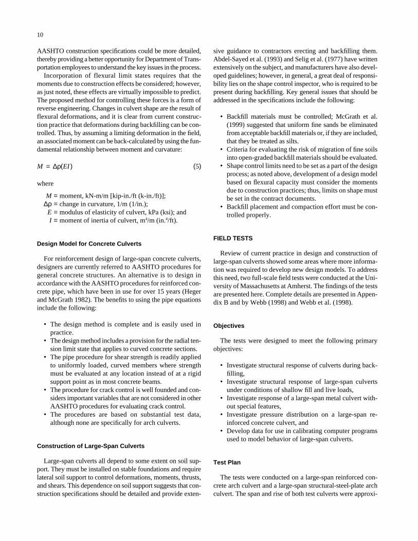
Incorporation of flexural limit states requires that themoments due to construction effects be considered; however,as just noted, these effects are virtually impossible to predict.The proposed method for controlling these forces is a form ofreverse engineering. Changes in culvert shape are the result offlexural deformations, and it is clear from current construc-tion practice that deformations during backfilling can be con-trolled. Thus, by assuming a limiting deformation in the field,an associated moment can be back-calculated by using the fun-damental relationship between moment and curvature:
where
M = moment, kN-m/m [kip-in./ft (k-in./ft)];∆ρ = change in curvature, 1/m (1/in.);
E = modulus of elasticity of culvert, kPa (ksi); andI = moment of inertia of culvert, m4/m (in.4/ft).
Design Model for Concrete Culverts
For reinforcement design of large-span concrete culverts,designers are currently referred to AASHTO procedures forgeneral concrete structures. An alternative is to design inaccordance with the AASHTO procedures for reinforced con-crete pipe, which have been in use for over 15 years (Hegerand McGrath 1982). The benefits to using the pipe equationsinclude the following:
• The design method is complete and is easily used inpractice.
• The design method includes a provision for the radial ten-sion limit state that applies to curved concrete sections.
• The pipe procedure for shear strength is readily appliedto uniformly loaded, curved members where strengthmust be evaluated at any location instead of at a rigidsupport point as in most concrete beams.
• The procedure for crack control is well founded and con-siders important variables that are not considered in otherAASHTO procedures for evaluating crack control.
• The procedures are based on substantial test data,although none are specifically for arch culverts.
Construction of Large-Span Culverts
Large-span culverts all depend to some extent on soil sup-port. They must be installed on stable foundations and requirelateral soil support to control deformations, moments, thrusts,and shears. This dependence on soil support suggests that con-struction specifications should be detailed and provide exten-
M EI= ( ) ( )∆ρ 5
10
sive guidance to contractors erecting and backfilling them.Abdel-Sayed et al. (1993) and Selig et al. (1977) have writtenextensively on the subject, and manufacturers have also devel-oped guidelines; however, in general, a great deal of responsi-bility lies on the shape control inspector, who is required to bepresent during backfilling. Key general issues that should beaddressed in the specifications include the following:
• Backfill materials must be controlled; McGrath et al.(1999) suggested that uniform fine sands be eliminatedfrom acceptable backfill materials or, if they are included,that they be treated as silts.
• Criteria for evaluating the risk of migration of fine soilsinto open-graded backfill materials should be evaluated.
• Shape control limits need to be set as a part of the designprocess; as noted above, development of a design modelbased on flexural capacity must consider the momentsdue to construction practices; thus, limits on shape mustbe set in the contract documents.
• Backfill placement and compaction effort must be con-trolled properly.
FIELD TESTS
Review of current practice in design and construction oflarge-span culverts showed some areas where more informa-tion was required to develop new design models. To addressthis need, two full-scale field tests were conducted at the Uni-versity of Massachusetts at Amherst. The findings of the testsare presented here. Complete details are presented in Appen-dix B and by Webb (1998) and Webb et al. (1998).
Objectives
The tests were designed to meet the following primaryobjectives:
• Investigate structural response of culverts during back-filling,
• Investigate structural response of large-span culvertsunder conditions of shallow fill and live loads,
• Investigate response of a large-span metal culvert with-out special features,
• Investigate pressure distribution on a large-span re-inforced concrete culvert, and
• Develop data for use in calibrating computer programsused to model behavior of large-span culverts.
Test Plan
The tests were conducted on a large-span reinforced con-crete arch culvert and a large-span structural-steel-plate archculvert. The span and rise of both test culverts were approxi-
11
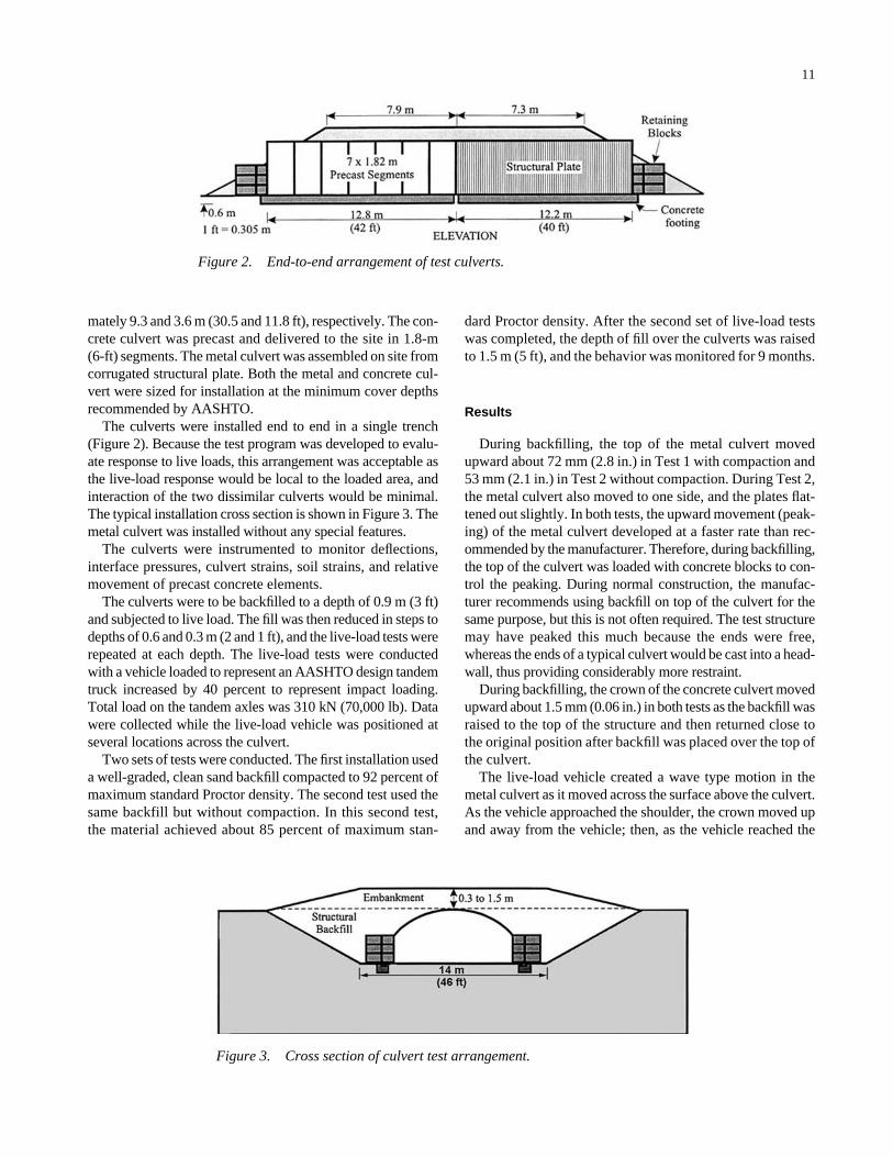
mately 9.3 and 3.6 m (30.5 and 11.8 ft), respectively. The con-crete culvert was precast and delivered to the site in 1.8-m(6-ft) segments. The metal culvert was assembled on site fromcorrugated structural plate. Both the metal and concrete cul-vert were sized for installation at the minimum cover depthsrecommended by AASHTO.
The culverts were installed end to end in a single trench(Figure 2). Because the test program was developed to evalu-ate response to live loads, this arrangement was acceptable asthe live-load response would be local to the loaded area, andinteraction of the two dissimilar culverts would be minimal.The typical installation cross section is shown in Figure 3. Themetal culvert was installed without any special features.
The culverts were instrumented to monitor deflections,interface pressures, culvert strains, soil strains, and relativemovement of precast concrete elements.
The culverts were to be backfilled to a depth of 0.9 m (3 ft)and subjected to live load. The fill was then reduced in steps todepths of 0.6 and 0.3 m (2 and 1 ft), and the live-load tests wererepeated at each depth. The live-load tests were conductedwith a vehicle loaded to represent an AASHTO design tandemtruck increased by 40 percent to represent impact loading.Total load on the tandem axles was 310 kN (70,000 lb). Datawere collected while the live-load vehicle was positioned atseveral locations across the culvert.
Two sets of tests were conducted. The first installation useda well-graded, clean sand backfill compacted to 92 percent ofmaximum standard Proctor density. The second test used thesame backfill but without compaction. In this second test,the material achieved about 85 percent of maximum stan-
dard Proctor density. After the second set of live-load testswas completed, the depth of fill over the culverts was raisedto 1.5 m (5 ft), and the behavior was monitored for 9 months.
Results
During backfilling, the top of the metal culvert movedupward about 72 mm (2.8 in.) in Test 1 with compaction and53 mm (2.1 in.) in Test 2 without compaction. During Test 2,the metal culvert also moved to one side, and the plates flat-tened out slightly. In both tests, the upward movement (peak-ing) of the metal culvert developed at a faster rate than rec-ommended by the manufacturer. Therefore, during backfilling,the top of the culvert was loaded with concrete blocks to con-trol the peaking. During normal construction, the manufac-turer recommends using backfill on top of the culvert for thesame purpose, but this is not often required. The test structuremay have peaked this much because the ends were free,whereas the ends of a typical culvert would be cast into a head-wall, thus providing considerably more restraint.
During backfilling, the crown of the concrete culvert movedupward about 1.5 mm (0.06 in.) in both tests as the backfill wasraised to the top of the structure and then returned close tothe original position after backfill was placed over the top ofthe culvert.
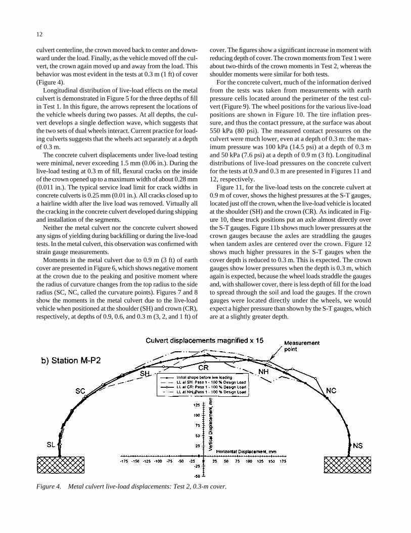
The live-load vehicle created a wave type motion in themetal culvert as it moved across the surface above the culvert.As the vehicle approached the shoulder, the crown moved upand away from the vehicle; then, as the vehicle reached the
Figure 2. End-to-end arrangement of test culverts.
Figure 3. Cross section of culvert test arrangement.
12
culvert centerline, the crown moved back to center and down-ward under the load. Finally, as the vehicle moved off the cul-vert, the crown again moved up and away from the load. Thisbehavior was most evident in the tests at 0.3 m (1 ft) of cover(Figure 4).
Longitudinal distribution of live-load effects on the metalculvert is demonstrated in Figure 5 for the three depths of fillin Test 1. In this figure, the arrows represent the locations ofthe vehicle wheels during two passes. At all depths, the cul-vert develops a single deflection wave, which suggests thatthe two sets of dual wheels interact. Current practice for load-ing culverts suggests that the wheels act separately at a depthof 0.3 m.
The concrete culvert displacements under live-load testingwere minimal, never exceeding 1.5 mm (0.06 in.). During thelive-load testing at 0.3 m of fill, flexural cracks on the insideof the crown opened up to a maximum width of about 0.28 mm(0.011 in.). The typical service load limit for crack widths inconcrete culverts is 0.25 mm (0.01 in.). All cracks closed up toa hairline width after the live load was removed. Virtually allthe cracking in the concrete culvert developed during shippingand installation of the segments.
Neither the metal culvert nor the concrete culvert showedany signs of yielding during backfilling or during the live-loadtests. In the metal culvert, this observation was confirmed withstrain gauge measurements.
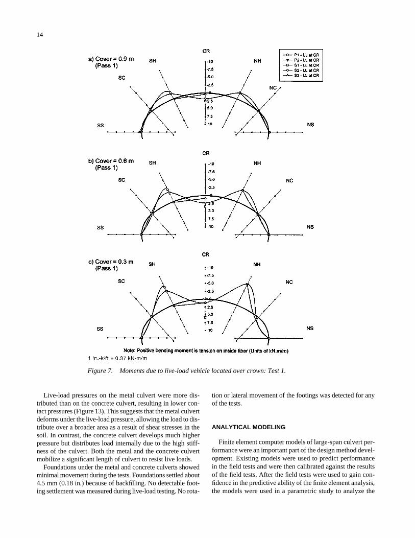
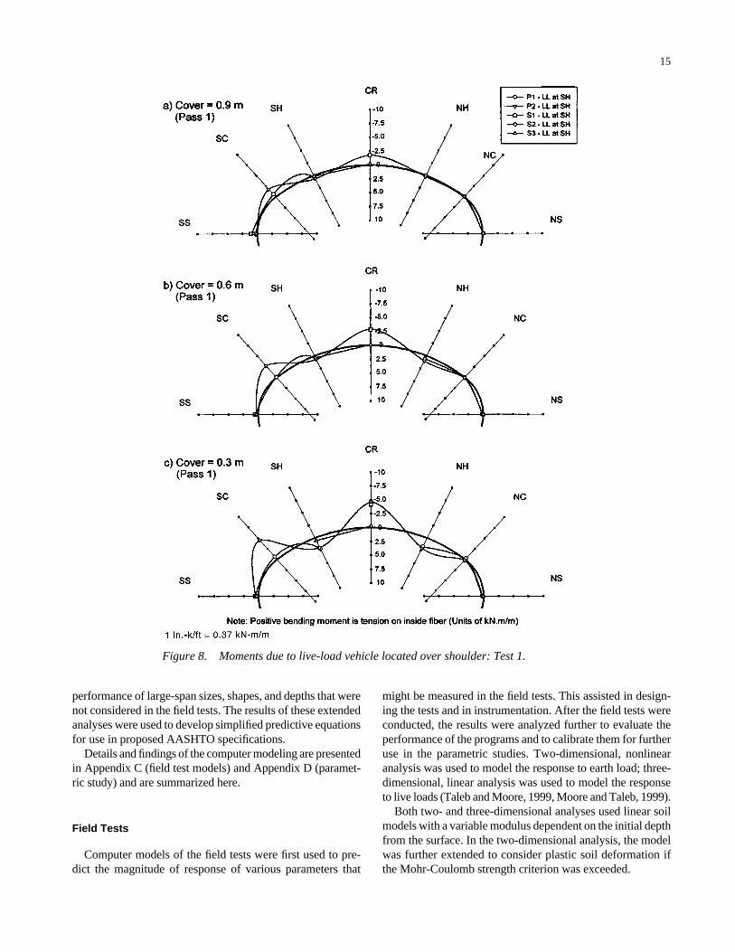
Moments in the metal culvert due to 0.9 m (3 ft) of earthcover are presented in Figure 6, which shows negative momentat the crown due to the peaking and positive moment wherethe radius of curvature changes from the top radius to the sideradius (SC, NC, called the curvature points). Figures 7 and 8show the moments in the metal culvert due to the live-loadvehicle when positioned at the shoulder (SH) and crown (CR),respectively, at depths of 0.9, 0.6, and 0.3 m (3, 2, and 1 ft) of
cover. The figures show a significant increase in moment withreducing depth of cover. The crown moments from Test 1 wereabout two-thirds of the crown moments in Test 2, whereas theshoulder moments were similar for both tests.
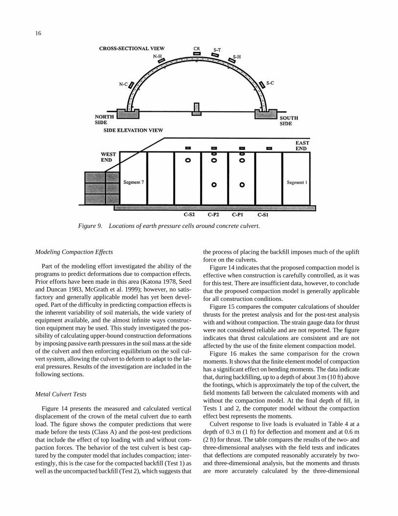
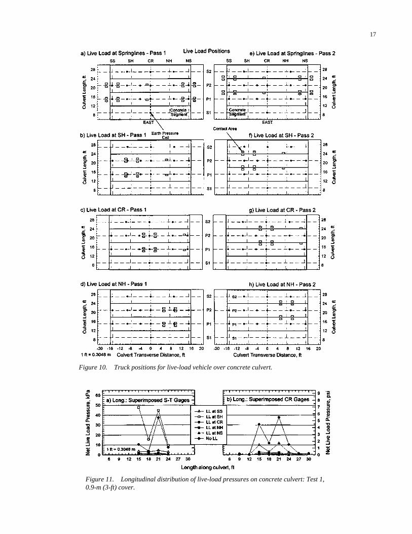
For the concrete culvert, much of the information derivedfrom the tests was taken from measurements with earthpressure cells located around the perimeter of the test cul-vert (Figure 9). The wheel positions for the various live-loadpositions are shown in Figure 10. The tire inflation pres-sure, and thus the contact pressure, at the surface was about550 kPa (80 psi). The measured contact pressures on theculvert were much lower, even at a depth of 0.3 m: the max-imum pressure was 100 kPa (14.5 psi) at a depth of 0.3 mand 50 kPa (7.6 psi) at a depth of 0.9 m (3 ft). Longitudinaldistributions of live-load pressures on the concrete culvertfor the tests at 0.9 and 0.3 m are presented in Figures 11 and12, respectively.
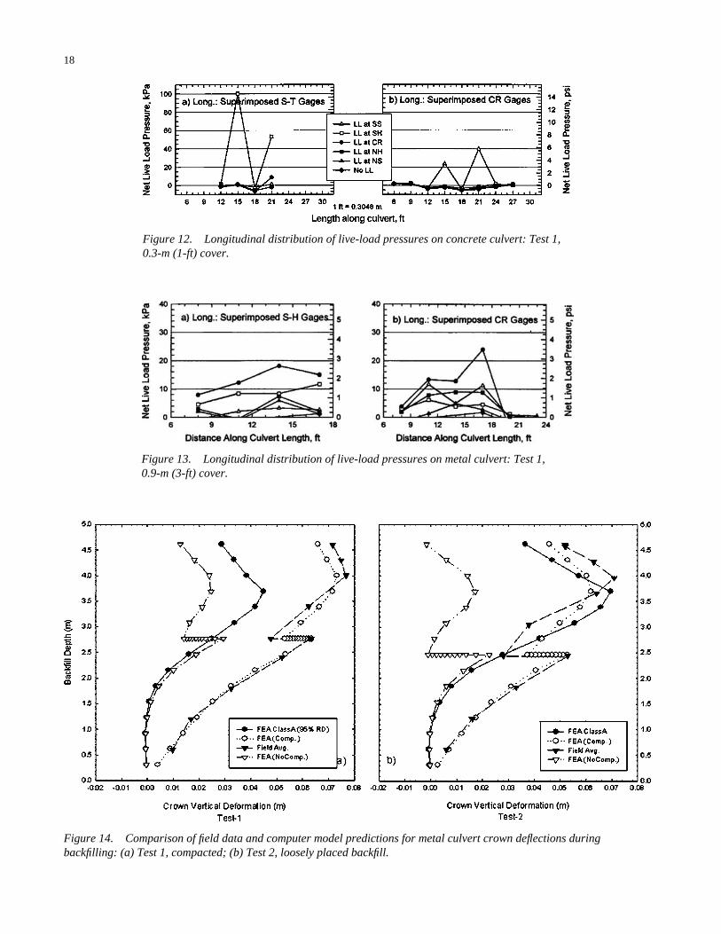
Figure 11, for the live-load tests on the concrete culvert at0.9 m of cover, shows the highest pressures at the S-T gauges,located just off the crown, when the live-load vehicle is locatedat the shoulder (SH) and the crown (CR). As indicated in Fig-ure 10, these truck positions put an axle almost directly overthe S-T gauges. Figure 11b shows much lower pressures at thecrown gauges because the axles are straddling the gaugeswhen tandem axles are centered over the crown. Figure 12shows much higher pressures in the S-T gauges when thecover depth is reduced to 0.3 m. This is expected. The crowngauges show lower pressures when the depth is 0.3 m, whichagain is expected, because the wheel loads straddle the gaugesand, with shallower cover, there is less depth of fill for the loadto spread through the soil and load the gauges. If the crowngauges were located directly under the wheels, we wouldexpect a higher pressure than shown by the S-T gauges, whichare at a slightly greater depth.
Figure 4. Metal culvert live-load displacements: Test 2, 0.3-m cover.
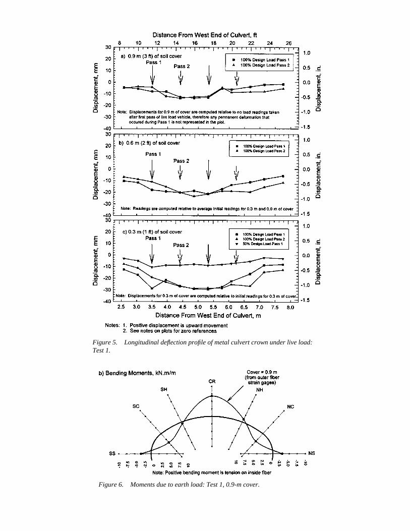
Figure 5. Longitudinal deflection profile of metal culvert crown under live load:Test 1.
Figure 6. Moments due to earth load: Test 1, 0.9-m cover.
14
Live-load pressures on the metal culvert were more dis-tributed than on the concrete culvert, resulting in lower con-tact pressures (Figure 13). This suggests that the metal culvertdeforms under the live-load pressure, allowing the load to dis-tribute over a broader area as a result of shear stresses in thesoil. In contrast, the concrete culvert develops much higherpressure but distributes load internally due to the high stiff-ness of the culvert. Both the metal and the concrete culvertmobilize a significant length of culvert to resist live loads.
Foundations under the metal and concrete culverts showedminimal movement during the tests. Foundations settled about4.5 mm (0.18 in.) because of backfilling. No detectable foot-ing settlement was measured during live-load testing. No rota-
tion or lateral movement of the footings was detected for anyof the tests.
ANALYTICAL MODELING
Finite element computer models of large-span culvert per-formance were an important part of the design method devel-opment. Existing models were used to predict performancein the field tests and were then calibrated against the resultsof the field tests. After the field tests were used to gain con-fidence in the predictive ability of the finite element analysis,the models were used in a parametric study to analyze the
Figure 7. Moments due to live-load vehicle located over crown: Test 1.
15
performance of large-span sizes, shapes, and depths that werenot considered in the field tests. The results of these extendedanalyses were used to develop simplified predictive equationsfor use in proposed AASHTO specifications.
Details and findings of the computer modeling are presentedin Appendix C (field test models) and Appendix D (paramet-ric study) and are summarized here.
Field Tests
Computer models of the field tests were first used to pre-dict the magnitude of response of various parameters that
might be measured in the field tests. This assisted in design-ing the tests and in instrumentation. After the field tests wereconducted, the results were analyzed further to evaluate theperformance of the programs and to calibrate them for furtheruse in the parametric studies. Two-dimensional, nonlinearanalysis was used to model the response to earth load; three-dimensional, linear analysis was used to model the responseto live loads (Taleb and Moore, 1999, Moore and Taleb, 1999).
Both two- and three-dimensional analyses used linear soilmodels with a variable modulus dependent on the initial depthfrom the surface. In the two-dimensional analysis, the modelwas further extended to consider plastic soil deformation ifthe Mohr-Coulomb strength criterion was exceeded.
Figure 8. Moments due to live-load vehicle located over shoulder: Test 1.
16
Modeling Compaction Effects
Part of the modeling effort investigated the ability of theprograms to predict deformations due to compaction effects.Prior efforts have been made in this area (Katona 1978, Seedand Duncan 1983, McGrath et al. 1999); however, no satis-factory and generally applicable model has yet been devel-oped. Part of the difficulty in predicting compaction effects isthe inherent variability of soil materials, the wide variety ofequipment available, and the almost infinite ways construc-tion equipment may be used. This study investigated the pos-sibility of calculating upper-bound construction deformationsby imposing passive earth pressures in the soil mass at the sideof the culvert and then enforcing equilibrium on the soil cul-vert system, allowing the culvert to deform to adapt to the lat-eral pressures. Results of the investigation are included in thefollowing sections.
Metal Culvert Tests
Figure 14 presents the measured and calculated verticaldisplacement of the crown of the metal culvert due to earthload. The figure shows the computer predictions that weremade before the tests (Class A) and the post-test predictionsthat include the effect of top loading with and without com-paction forces. The behavior of the test culvert is best cap-tured by the computer model that includes compaction; inter-estingly, this is the case for the compacted backfill (Test 1) aswell as the uncompacted backfill (Test 2), which suggests that
the process of placing the backfill imposes much of the upliftforce on the culverts.
Figure 14 indicates that the proposed compaction model iseffective when construction is carefully controlled, as it wasfor this test. There are insufficient data, however, to concludethat the proposed compaction model is generally applicablefor all construction conditions.
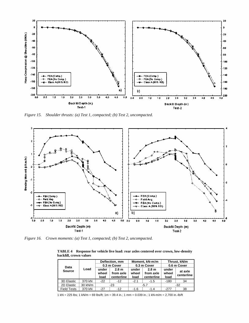
Figure 15 compares the computer calculations of shoulderthrusts for the pretest analysis and for the post-test analysiswith and without compaction. The strain gauge data for thrustwere not considered reliable and are not reported. The figureindicates that thrust calculations are consistent and are notaffected by the use of the finite element compaction model.
Figure 16 makes the same comparison for the crownmoments. It shows that the finite element model of compactionhas a significant effect on bending moments. The data indicatethat, during backfilling, up to a depth of about 3 m (10 ft) abovethe footings, which is approximately the top of the culvert, thefield moments fall between the calculated moments with andwithout the compaction model. At the final depth of fill, inTests 1 and 2, the computer model without the compactioneffect best represents the moments.
Culvert response to live loads is evaluated in Table 4 at adepth of 0.3 m (1 ft) for deflection and moment and at 0.6 m(2 ft) for thrust. The table compares the results of the two- andthree-dimensional analyses with the field tests and indicatesthat deflections are computed reasonably accurately by two-and three-dimensional analysis, but the moments and thrustsare more accurately calculated by the three-dimensional
Figure 9. Locations of earth pressure cells around concrete culvert.
17
Figure 10. Truck positions for live-load vehicle over concrete culvert.
Figure 11. Longitudinal distribution of live-load pressures on concrete culvert: Test 1,0.9-m (3-ft) cover.
18
Figure 12. Longitudinal distribution of live-load pressures on concrete culvert: Test 1,0.3-m (1-ft) cover.
Figure 14. Comparison of field data and computer model predictions for metal culvert crown deflections duringbackfilling: (a) Test 1, compacted; (b) Test 2, loosely placed backfill.
Figure 13. Longitudinal distribution of live-load pressures on metal culvert: Test 1, 0.9-m (3-ft) cover.
Deflection, mm Moment, kN-m/m Thrust, kN/m 0.3 m Cover 0.3 m Cover 0.6 m Cover Data
Source Load under wheel load
2.8 m from axle centerline
under wheel load
2.8 m from axle centerline
under wheel load
at axle centerline
3D Elastic 370 kN -22 -12 -2.1 -1.5 -180 34 2D Elastic 30 kN/m -23 -5.7 -32 Field Tests 370 kN -27 -12 -1.6 -1.4 -277 38
1 kN = 225 lbs; 1 kN/m = 69 lbs/ft; 1m = 39.4 in.; 1 mm = 0.039 in.; 1 kN-m/m = 2,700 in.-lb/ft
Figure 15. Shoulder thrusts: (a) Test 1, compacted; (b) Test 2, uncompacted.
Figure 16. Crown moments: (a) Test 1, compacted; (b) Test 2, uncompacted.
TABLE 4 Response for vehicle live load: rear axles centered over crown, low-densitybackfill, crown values
20
method. This is not surprising because response to live load isa three-dimensional behavior.
Concrete Culvert Tests
Analysis of the concrete field tests focused on the interfacepressures, as these pressures are commonly used as a basis forsimplified design. As for the metal culvert tests, the resultswere evaluated with two- and three-dimensional computermodels.
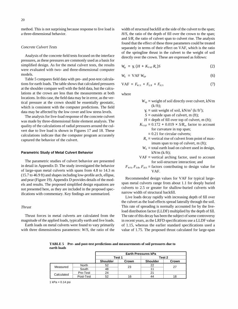
Table 5 compares field data with pre- and post-test calcula-tions for earth loads. The table shows that calculated pressuresat the shoulder compare well with the field data, but the calcu-lations at the crown are less than the measurements at bothlocations. In this case, the field data may be in error, as the ver-tical pressure at the crown should be essentially geostatic,which is consistent with the computer predictions. The fielddata may be affected by the low cover and low stress levels.
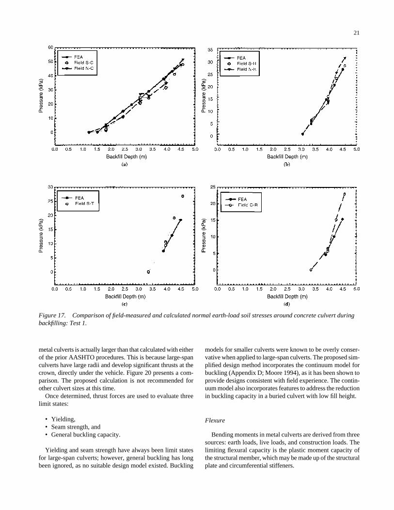
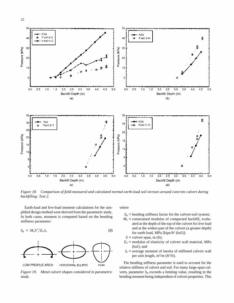
The analysis for live-load response of the concrete culvertwas made by three-dimensional finite element analysis. Thequality of the calculations of radial pressures around the cul-vert due to live load is shown in Figures 17 and 18. Thesecalculations indicate that the computer program accuratelycaptured the behavior of the culvert.
Parametric Study of Metal Culvert Behavior
The parametric studies of culvert behavior are presentedin detail in Appendix D. The study investigated the behaviorof large-span metal culverts with spans from 4.8 to 14.3 m(15.7 to 46.9 ft) and shapes including low-profile arch, ellipse,and pear (Figure 19). Appendix D provides details of the mod-els and results. The proposed simplified design equations arenot presented here, as they are included in the proposed spec-ifications with commentary. Key findings are summarized.
Thrust
Thrust forces in metal culverts are calculated from themagnitude of the applied loads, typically earth and live loads.
Earth loads on metal culverts were found to vary primarilywith three dimensionless parameters: W/S, the ratio of the
width of structural backfill at the side of the culvert to the span;H/S, the ratio of the depth of fill over the crown to the span;and S/R, the ratio of culvert span to culvert rise. The analysisfound that the effect of these three parameters could be treatedseparately in terms of their effect on VAF, which is the ratioof the springline thrust in the culvert to the weight of soildirectly over the crown. These are expressed as follows:
where
Wsp = weight of soil directly over culvert, kN/m(k/ft);
γs = unit weight of soil, kN/m3 (k/ft3);S = outside span of culvert, m (ft);H = depth of fill over top of culvert, m (ft);
KVAF = 0.172 + 0.019 × S/Ru, factor to accountfor curvature in top span;
= 0.21 for circular culverts;Ru = vertical rise of culvert from point of max-
imum span to top of culvert, m (ft);WE = total earth load on culvert used in design,
kN/m (k/ft);VAF = vertical arching factor, used to account
for soil-structure interaction; andFW/S, FS/R, FH/S = factors contributing to design value for
VAF.
Recommended design values for VAF for typical large-span metal culverts range from about 1.1 for deeply buriedculverts to 2.5 or greater for shallow-buried culverts withnarrow width of structural backfill.
Live loads decay rapidly with increasing depth of fill overthe culvert as the load effects spread laterally through the soil.This rate of spreading is normally accounted for by the live-load distribution factor (LLDF) multiplied by the depth of fill.The rate of this decay has been the subject of some controversyin recent years, as the LRFD specifications use a LLDF valueof 1.15, whereas the earlier standard specifications used avalue of 1.75. The proposed thrust calculated for large-span
VAF = + + ( )F F FW S S R H S 7
W WE SPVAF= ( )6
W H K R Ssp s VAF u= +( ) ( )γ 2
Earth Pressures kPa Test 1 Test 2
Shoulder ShoulderNorth 52 22Measured South 48
2311
27
Pre-Test 24 21Calculated Post-Test 52 16 44 18
1 kPa = 0.14 psi
Crown Crown
TABLE 5 Pre- and post-test predictions and measurements of soil pressures due to earth loads
21
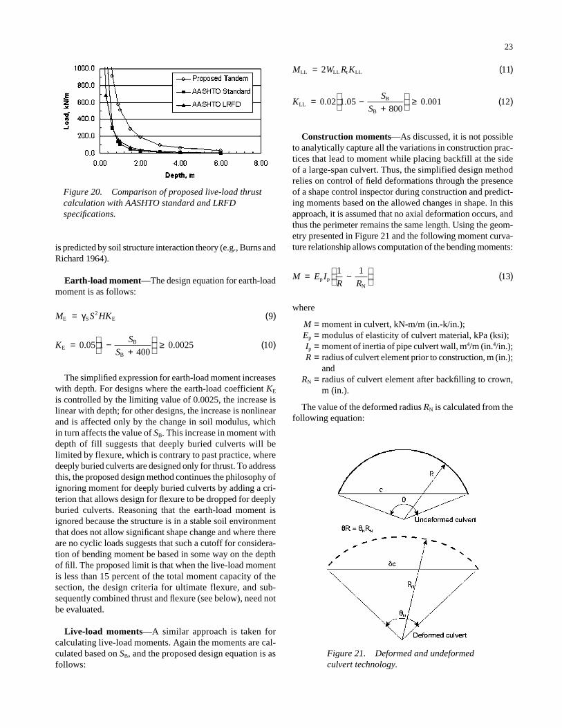
metal culverts is actually larger than that calculated with eitherof the prior AASHTO procedures. This is because large-spanculverts have large radii and develop significant thrusts at thecrown, directly under the vehicle. Figure 20 presents a com-parison. The proposed calculation is not recommended forother culvert sizes at this time.
Once determined, thrust forces are used to evaluate threelimit states:
• Yielding,• Seam strength, and• General buckling capacity.
Yielding and seam strength have always been limit statesfor large-span culverts; however, general buckling has longbeen ignored, as no suitable design model existed. Buckling
models for smaller culverts were known to be overly conser-vative when applied to large-span culverts. The proposed sim-plified design method incorporates the continuum model forbuckling (Appendix D; Moore 1994), as it has been shown toprovide designs consistent with field experience. The contin-uum model also incorporates features to address the reductionin buckling capacity in a buried culvert with low fill height.
Flexure
Bending moments in metal culverts are derived from threesources: earth loads, live loads, and construction loads. Thelimiting flexural capacity is the plastic moment capacity ofthe structural member, which may be made up of the structuralplate and circumferential stiffeners.
Figure 17. Comparison of field-measured and calculated normal earth-load soil stresses around concrete culvert duringbackfilling: Test 1.
22
Earth-load and live-load moment calculations for the sim-plified design method were derived from the parametric study.In both cases, moment is computed based on the bendingstiffness parameter:
S M S E IB S3
P P= ( )8
where
SB = bending stiffness factor for the culvert-soil system;MS = constrained modulus of compacted backfill, evalu-
ated at the depth of the top of the culvert for live loadand at the widest part of the culvert (a greater depth)for earth load, MPa [kips/ft2 (ksf)];
S = culvert span, m (ft);EP = modulus of elasticity of culvert wall material, MPa
(ksf); andIP = average moment of inertia of stiffened culvert wall
per unit length, m4/m (ft4/ft).
The bending stiffness parameter is used to account for therelative stiffness of culvert and soil. For many large-span cul-verts, parameter SB exceeds a limiting value, resulting in thebending moment being independent of culvert properties. This
Figure 18. Comparison of field-measured and calculated normal earth-load soil stresses around concrete culvert duringbackfilling: Test 2.
Figure 19. Metal culvert shapes considered in parametricstudy.
23
Construction moments—As discussed, it is not possibleto analytically capture all the variations in construction prac-tices that lead to moment while placing backfill at the sideof a large-span culvert. Thus, the simplified design methodrelies on control of field deformations through the presenceof a shape control inspector during construction and predict-ing moments based on the allowed changes in shape. In thisapproach, it is assumed that no axial deformation occurs, andthus the perimeter remains the same length. Using the geom-etry presented in Figure 21 and the following moment curva-ture relationship allows computation of the bending moments:
where
M = moment in culvert, kN-m/m (in.-k/in.);Ep = modulus of elasticity of culvert material, kPa (ksi);Ip = moment of inertia of pipe culvert wall, m4/m (in.4/in.);R = radius of culvert element prior to construction, m (in.);
andRN = radius of culvert element after backfilling to crown,
m (in.).
The value of the deformed radius RN is calculated from thefollowing equation:
M E IR R
= −
( )p pN
1 113
KS
SLL
B
B
= −+
≥ ( )0 02 1 05
8000 001 12. . .
M W R KLL LL t LL= ( )2 11
is predicted by soil structure interaction theory (e.g., Burns andRichard 1964).
Earth-load moment—The design equation for earth-loadmoment is as follows:
The simplified expression for earth-load moment increaseswith depth. For designs where the earth-load coefficient KE
is controlled by the limiting value of 0.0025, the increase islinear with depth; for other designs, the increase is nonlinearand is affected only by the change in soil modulus, whichin turn affects the value of SB. This increase in moment withdepth of fill suggests that deeply buried culverts will belimited by flexure, which is contrary to past practice, wheredeeply buried culverts are designed only for thrust. To addressthis, the proposed design method continues the philosophy ofignoring moment for deeply buried culverts by adding a cri-terion that allows design for flexure to be dropped for deeplyburied culverts. Reasoning that the earth-load moment isignored because the structure is in a stable soil environmentthat does not allow significant shape change and where thereare no cyclic loads suggests that such a cutoff for considera-tion of bending moment be based in some way on the depthof fill. The proposed limit is that when the live-load momentis less than 15 percent of the total moment capacity of thesection, the design criteria for ultimate flexure, and sub-sequently combined thrust and flexure (see below), need notbe evaluated.
Live-load moments—A similar approach is taken forcalculating live-load moments. Again the moments are cal-culated based on SB, and the proposed design equation is asfollows:
KS
SE
B
B
= −+
≥ ( )0 05 1
4000 0025 10. .
M S HKE S E= ( )γ 2 9
Figure 20. Comparison of proposed live-load thrustcalculation with AASHTO standard and LRFDspecifications.
Figure 21. Deformed and undeformedculvert technology.
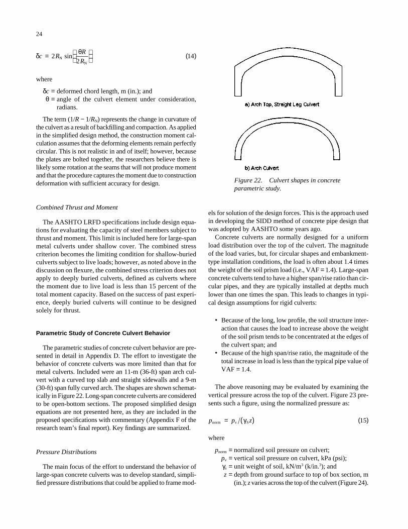
where
δc = deformed chord length, m (in.); andθ = angle of the culvert element under consideration,
radians.
The term (1/R − 1/RN) represents the change in curvature ofthe culvert as a result of backfilling and compaction. As appliedin the simplified design method, the construction moment cal-culation assumes that the deforming elements remain perfectlycircular. This is not realistic in and of itself; however, becausethe plates are bolted together, the researchers believe there islikely some rotation at the seams that will not produce momentand that the procedure captures the moment due to constructiondeformation with sufficient accuracy for design.
Combined Thrust and Moment
The AASHTO LRFD specifications include design equa-tions for evaluating the capacity of steel members subject tothrust and moment. This limit is included here for large-spanmetal culverts under shallow cover. The combined stresscriterion becomes the limiting condition for shallow-buriedculverts subject to live loads; however, as noted above in thediscussion on flexure, the combined stress criterion does notapply to deeply buried culverts, defined as culverts wherethe moment due to live load is less than 15 percent of thetotal moment capacity. Based on the success of past experi-ence, deeply buried culverts will continue to be designedsolely for thrust.
Parametric Study of Concrete Culvert Behavior
The parametric studies of concrete culvert behavior are pre-sented in detail in Appendix D. The effort to investigate thebehavior of concrete culverts was more limited than that formetal culverts. Included were an 11-m (36-ft) span arch cul-vert with a curved top slab and straight sidewalls and a 9-m(30-ft) span fully curved arch. The shapes are shown schemat-ically in Figure 22. Long-span concrete culverts are consideredto be open-bottom sections. The proposed simplified designequations are not presented here, as they are included in theproposed specifications with commentary (Appendix F of theresearch team’s final report). Key findings are summarized.
Pressure Distributions
The main focus of the effort to understand the behavior oflarge-span concrete culverts was to develop standard, simpli-fied pressure distributions that could be applied to frame mod-
δ θc R
R
R=
( )22
14NN
sin
24
els for solution of the design forces. This is the approach usedin developing the SIDD method of concrete pipe design thatwas adopted by AASHTO some years ago.
Concrete culverts are normally designed for a uniformload distribution over the top of the culvert. The magnitudeof the load varies, but, for circular shapes and embankment-type installation conditions, the load is often about 1.4 timesthe weight of the soil prism load (i.e., VAF = 1.4). Large-spanconcrete culverts tend to have a higher span/rise ratio than cir-cular pipes, and they are typically installed at depths muchlower than one times the span. This leads to changes in typi-cal design assumptions for rigid culverts:
• Because of the long, low profile, the soil structure inter-action that causes the load to increase above the weightof the soil prism tends to be concentrated at the edges ofthe culvert span; and
• Because of the high span/rise ratio, the magnitude of thetotal increase in load is less than the typical pipe value ofVAF = 1.4.
The above reasoning may be evaluated by examining thevertical pressure across the top of the culvert. Figure 23 pre-sents such a figure, using the normalized pressure as:
where
pnorm = normalized soil pressure on culvert;pv = vertical soil pressure on culvert, kPa (psi);γs = unit weight of soil, kN/m3 (k/in.3); andz = depth from ground surface to top of box section, m
(in.); z varies across the top of the culvert (Figure 24).
p p znorm v S= ( ) ( )γ 15
Figure 22. Culvert shapes in concreteparametric study.
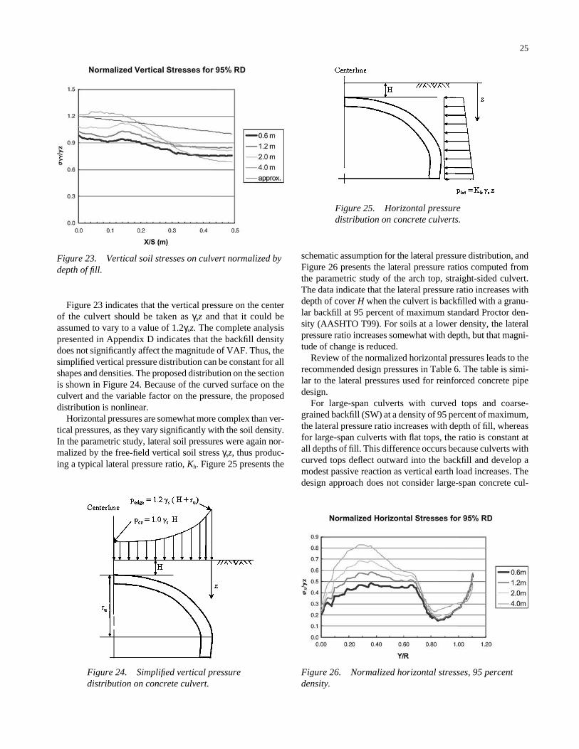
25
Figure 23. Vertical soil stresses on culvert normalized bydepth of fill.
Figure 24. Simplified vertical pressuredistribution on concrete culvert.
Figure 25. Horizontal pressuredistribution on concrete culverts.
Figure 26. Normalized horizontal stresses, 95 percentdensity.
Figure 23 indicates that the vertical pressure on the centerof the culvert should be taken as γsz and that it could beassumed to vary to a value of 1.2γsz. The complete analysispresented in Appendix D indicates that the backfill densitydoes not significantly affect the magnitude of VAF. Thus, thesimplified vertical pressure distribution can be constant for allshapes and densities. The proposed distribution on the sectionis shown in Figure 24. Because of the curved surface on theculvert and the variable factor on the pressure, the proposeddistribution is nonlinear.
Horizontal pressures are somewhat more complex than ver-tical pressures, as they vary significantly with the soil density.In the parametric study, lateral soil pressures were again nor-malized by the free-field vertical soil stress γsz, thus produc-ing a typical lateral pressure ratio, Kh. Figure 25 presents the
schematic assumption for the lateral pressure distribution, andFigure 26 presents the lateral pressure ratios computed fromthe parametric study of the arch top, straight-sided culvert.The data indicate that the lateral pressure ratio increases withdepth of cover H when the culvert is backfilled with a granu-lar backfill at 95 percent of maximum standard Proctor den-sity (AASHTO T99). For soils at a lower density, the lateralpressure ratio increases somewhat with depth, but that magni-tude of change is reduced.
Review of the normalized horizontal pressures leads to therecommended design pressures in Table 6. The table is simi-lar to the lateral pressures used for reinforced concrete pipedesign.
For large-span culverts with curved tops and coarse-grained backfill (SW) at a density of 95 percent of maximum,the lateral pressure ratio increases with depth of fill, whereasfor large-span culverts with flat tops, the ratio is constant atall depths of fill. This difference occurs because culverts withcurved tops deflect outward into the backfill and develop amodest passive reaction as vertical earth load increases. Thedesign approach does not consider large-span concrete cul-
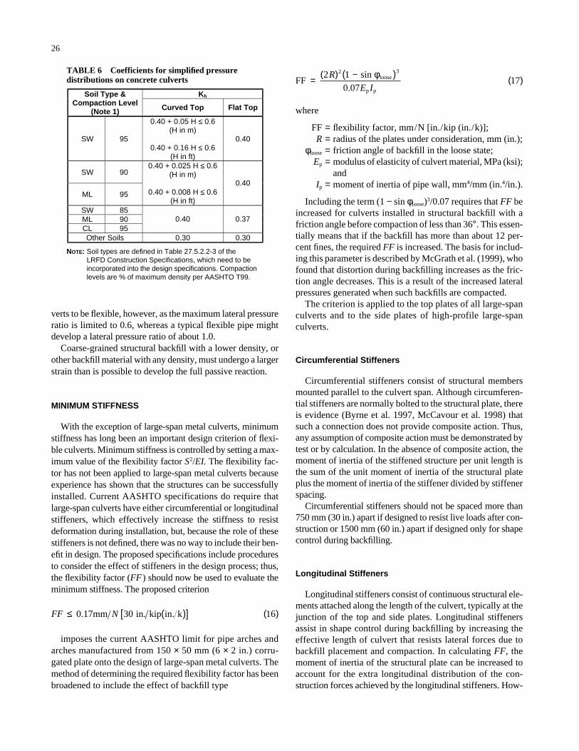
26
where
FF = flexibility factor, mm/N [in./kip (in./k)];R = radius of the plates under consideration, mm (in.);
φloose = friction angle of backfill in the loose state;Ep = modulus of elasticity of culvert material, MPa (ksi);
andIp = moment of inertia of pipe wall, mm4/mm (in.4/in.).
Including the term (1 − sin φloose)3/0.07 requires that FF beincreased for culverts installed in structural backfill with afriction angle before compaction of less than 36°. This essen-tially means that if the backfill has more than about 12 per-cent fines, the required FF is increased. The basis for includ-ing this parameter is described by McGrath et al. (1999), whofound that distortion during backfilling increases as the fric-tion angle decreases. This is a result of the increased lateralpressures generated when such backfills are compacted.
The criterion is applied to the top plates of all large-spanculverts and to the side plates of high-profile large-spanculverts.
Circumferential Stiffeners
Circumferential stiffeners consist of structural membersmounted parallel to the culvert span. Although circumferen-tial stiffeners are normally bolted to the structural plate, thereis evidence (Byrne et al. 1997, McCavour et al. 1998) thatsuch a connection does not provide composite action. Thus,any assumption of composite action must be demonstrated bytest or by calculation. In the absence of composite action, themoment of inertia of the stiffened structure per unit length isthe sum of the unit moment of inertia of the structural plateplus the moment of inertia of the stiffener divided by stiffenerspacing.
Circumferential stiffeners should not be spaced more than750 mm (30 in.) apart if designed to resist live loads after con-struction or 1500 mm (60 in.) apart if designed only for shapecontrol during backfilling.
Longitudinal Stiffeners
Longitudinal stiffeners consist of continuous structural ele-ments attached along the length of the culvert, typically at thejunction of the top and side plates. Longitudinal stiffenersassist in shape control during backfilling by increasing theeffective length of culvert that resists lateral forces due tobackfill placement and compaction. In calculating FF, themoment of inertia of the structural plate can be increased toaccount for the extra longitudinal distribution of the con-struction forces achieved by the longitudinal stiffeners. How-
FF2 loose
p p
=( ) −( ) ( )R
E I
2 31
0 0717
sin
.
φ
verts to be flexible, however, as the maximum lateral pressureratio is limited to 0.6, whereas a typical flexible pipe mightdevelop a lateral pressure ratio of about 1.0.
Coarse-grained structural backfill with a lower density, orother backfill material with any density, must undergo a largerstrain than is possible to develop the full passive reaction.
MINIMUM STIFFNESS
With the exception of large-span metal culverts, minimumstiffness has long been an important design criterion of flexi-ble culverts. Minimum stiffness is controlled by setting a max-imum value of the flexibility factor S2/EI. The flexibility fac-tor has not been applied to large-span metal culverts becauseexperience has shown that the structures can be successfullyinstalled. Current AASHTO specifications do require thatlarge-span culverts have either circumferential or longitudinalstiffeners, which effectively increase the stiffness to resistdeformation during installation, but, because the role of thesestiffeners is not defined, there was no way to include their ben-efit in design. The proposed specifications include proceduresto consider the effect of stiffeners in the design process; thus,the flexibility factor (FF) should now be used to evaluate theminimum stiffness. The proposed criterion
imposes the current AASHTO limit for pipe arches andarches manufactured from 150 × 50 mm (6 × 2 in.) corru-gated plate onto the design of large-span metal culverts. Themethod of determining the required flexibility factor has beenbroadened to include the effect of backfill type
FF N≤ ( )[ ] ( )0.17mm in. kip in. k30 16
Kh Soil Type &Compaction Level
(Note 1) Curved Top Flat Top
SW
0.40 + 0.05 H ≤ 0.6 (H in m)
0.40 + 0.16 H ≤ 0.6 (H in ft)
0.40
SW
ML
0.40 + 0.025 H ≤ 0.6 (H in m)
0.40 + 0.008 H ≤ 0.6 (H in ft)
0.40
SWMLCL
95
90
95
859095
0.40 0.37
Other Soils 0.30 0.30
NOTE: Soil types are defined in Table 27.5.2.2-3 of the LRFD Construction Specifications, which need to be incorporated into the design specifications. Compaction levels are % of maximum density per AASHTO T99.
TABLE 6 Coefficients for simplified pressuredistributions on concrete culverts
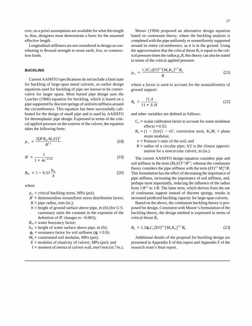
27
ever, no a priori assumptions are available for what this lengthis; thus, designers must demonstrate a basis for the assumedeffective length.
Longitudinal stiffeners are not considered in design as con-tributing to flexural strength to resist earth, live, or construc-tion loads.
BUCKLING
Current AASHTO specifications do not include a limit statefor buckling of large-span metal culverts, as earlier designequations used for buckling of pipe are known to be conser-vative for larger spans. Most buried pipe design uses theLuscher (1966) equation for buckling, which is based on apipe supported by discreet springs of uniform stiffness aroundthe circumference. This equation has been successfully cali-brated for the design of small pipe and is used by AASHTOfor thermoplastic pipe design. Expressed in terms of the criti-cal applied pressure on the exterior of the culvert, the equationtakes the following form:
where
pcr = critical buckling stress, MPa (psi);B′ = dimensionless nonuniform stress distribution factor;R = pipe radius, mm (in.);h = height of ground surface above pipe, m (ft) (for U.S.
customary units the constant in the exponent of thedefinition of B′ changes to −0.065);
RW = water buoyancy factor;hW = height of water surface above pipe, m (ft);φS = resistance factor for soil stiffness (φs = 0.9);MS = constrained soil modulus, MPa (psi);E = modulus of elasticity of culvert, MPa (psi); andI = moment of inertia of culvert wall, mm4/mm (in.4/in.).
Rh
hW
W= − ( )1 0 33 20.
′ =+
( )−Be h
1
1 4190 21.
pB R M EI
Rcr
W S= ′( ) ( )218
3
1 5.
Moore (1994) proposed an alternative design equationbased on continuum theory, where the buckling analysis iscompleted with the pipe uniformly or nonuniformly supportedaround its entire circumference, as it is in the ground. Usingthe approximation that the critical thrust Rb is equal to the crit-ical pressure times the radius pcrR, this theory can also be statedin terms of the critical applied pressure:
where a factor is used to account for the nonuniformity ofground support:
and other variables are defined as follows:
Cn = scalar calibration factor to account for some nonlineareffects = 0.55;
Kb = (1 − 2ν)/(1 − ν)2, conversion term, Kb Ms = planestrain modulus;
ν = Poisson’s ratio of the soil; andR = radius of a circular pipe; S/2 is the closest approxi-
mation for a noncircular culvert, m (in.).
The current AASHTO design equation considers pipe andsoil stiffness in the term (MSEI)0.5/R1.5, whereas the continuumtheory considers the pipe stiffness with the term (EI)1/3 MS
2/3/R.This formulation has the effect of decreasing the importance ofpipe stiffness, increasing the importance of soil stiffness, and,perhaps most importantly, reducing the influence of the radiusfrom 1/R1.5 to 1/R. The latter term, which derives from the useof continuous support instead of discreet springs, results inincreased predicted buckling capacity for large-span culverts.
Based on the above, the continuum buckling theory is pro-posed for design. Consistent with Moore’s formulation of thebuckling theory, the design method is expressed in terms ofcritical thrust Rb
Additional details of the proposal for buckling design arepresented in Appendix E of this report and Appendix F of theresearch team’s final report.
R C EI M K Rb b n S b h= ( ) ( ) ( )1 2 231 3 2 3. φ
RS H
h =+
( )11 4
1122
.
pC EI M K R
Rcr
n S b h=( ) ( ) ( )1 2
211 3 2 3.
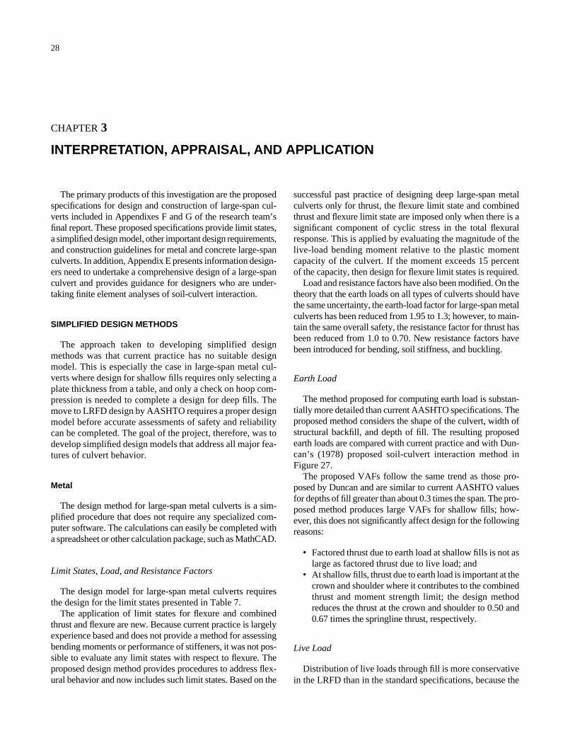
28
CHAPTER 3
INTERPRETATION, APPRAISAL, AND APPLICATION
The primary products of this investigation are the proposedspecifications for design and construction of large-span cul-verts included in Appendixes F and G of the research team’sfinal report. These proposed specifications provide limit states,a simplified design model, other important design requirements,and construction guidelines for metal and concrete large-spanculverts. In addition, Appendix E presents information design-ers need to undertake a comprehensive design of a large-spanculvert and provides guidance for designers who are under-taking finite element analyses of soil-culvert interaction.
SIMPLIFIED DESIGN METHODS
The approach taken to developing simplified designmethods was that current practice has no suitable designmodel. This is especially the case in large-span metal cul-verts where design for shallow fills requires only selecting aplate thickness from a table, and only a check on hoop com-pression is needed to complete a design for deep fills. Themove to LRFD design by AASHTO requires a proper designmodel before accurate assessments of safety and reliabilitycan be completed. The goal of the project, therefore, was todevelop simplified design models that address all major fea-tures of culvert behavior.
Metal
The design method for large-span metal culverts is a sim-plified procedure that does not require any specialized com-puter software. The calculations can easily be completed witha spreadsheet or other calculation package, such as MathCAD.
Limit States, Load, and Resistance Factors
The design model for large-span metal culverts requiresthe design for the limit states presented in Table 7.
The application of limit states for flexure and combinedthrust and flexure are new. Because current practice is largelyexperience based and does not provide a method for assessingbending moments or performance of stiffeners, it was not pos-sible to evaluate any limit states with respect to flexure. Theproposed design method provides procedures to address flex-ural behavior and now includes such limit states. Based on the
successful past practice of designing deep large-span metalculverts only for thrust, the flexure limit state and combinedthrust and flexure limit state are imposed only when there is asignificant component of cyclic stress in the total flexuralresponse. This is applied by evaluating the magnitude of thelive-load bending moment relative to the plastic momentcapacity of the culvert. If the moment exceeds 15 percent of the capacity, then design for flexure limit states is required.
Load and resistance factors have also been modified. On thetheory that the earth loads on all types of culverts should havethe same uncertainty, the earth-load factor for large-span metalculverts has been reduced from 1.95 to 1.3; however, to main-tain the same overall safety, the resistance factor for thrust hasbeen reduced from 1.0 to 0.70. New resistance factors havebeen introduced for bending, soil stiffness, and buckling.
Earth Load
The method proposed for computing earth load is substan-tially more detailed than current AASHTO specifications. Theproposed method considers the shape of the culvert, width ofstructural backfill, and depth of fill. The resulting proposedearth loads are compared with current practice and with Dun-can’s (1978) proposed soil-culvert interaction method inFigure 27.
The proposed VAFs follow the same trend as those pro-posed by Duncan and are similar to current AASHTO valuesfor depths of fill greater than about 0.3 times the span. The pro-posed method produces large VAFs for shallow fills; how-ever, this does not significantly affect design for the followingreasons:
• Factored thrust due to earth load at shallow fills is not aslarge as factored thrust due to live load; and
• At shallow fills, thrust due to earth load is important at thecrown and shoulder where it contributes to the combinedthrust and moment strength limit; the design methodreduces the thrust at the crown and shoulder to 0.50 and0.67 times the springline thrust, respectively.
Live Load
Distribution of live loads through fill is more conservativein the LRFD than in the standard specifications, because the
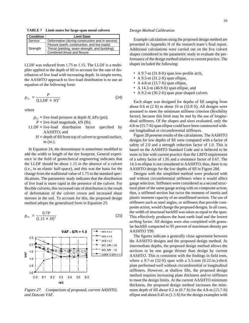
29
LLDF was reduced from 1.75 to 1.15. The LLDF is a multi-plier applied to the depth of fill to account for the rate of dis-tribution of live load with increasing depth. In simple terms,the AASHTO approach to live-load distribution is to use anequation of the following form:
where
pLL = live-load pressure at depth H, kPa (psi);P = live-load magnitude, kN (lb);
LLDF = live-load distribution factor specified byAASHTO; and
H = depth of fill from top of culvert to ground surface,m (in.).
In Equation 24, the denominator is sometimes modified toadd the width or length of the tire footprint. General experi-ence in the field of geotechnical engineering indicates thatthe LLDF should be about 1.15 in the absence of a culvert(i.e., in an elastic half-space), and this was the basis for thechange from the traditional value of 1.75 in the standard spec-ifications. The parametric study indicates that the distributionof live load is more rapid in the presence of the culvert. Forflexible culverts, this increased rate of distribution is the resultof deformation of the culvert crown and increased shearstresses in the soil. To account for this, the proposed designmethod adopts the generalized form in Equation 25:
pP
HLL
1=
×( )( )0 7
15252
.
.
pP
HLL
LLDF=
×( )( )
224
Design Method Calibration
Example calculations using the proposed design method arepresented in Appendix H of the research team’s final report.Additional calculations were carried out on the five culvertshapes considered in the parametric study to evaluate the per-formance of the design method relative to current practice. Theshapes included the following:
• A 9.7-m (31.8-ft) span low-profile arch,• A 9.5-m (31.2-ft) span ellipse,• A 4.8-m (15.7-ft) span ellipse,• A 14.3-m (46.9-ft) span ellipse, and• A 9.2-m (30.2-ft) span pear-shaped culvert.
Each shape was designed for depths of fill ranging fromabout 0.6 m (2 ft) to about 10 m (32.8 ft). All designs wereassumed to meet the minimum stiffness criterion (flexibilityfactor), because this limit may be met by the use of longitu-dinal stiffeners. Of the shapes and sizes evaluated, only the4.8-m (15.7-ft) span ellipse could have been constructed with-out longitudinal or circumferential stiffeners.
Figure 28 presents results of the calculations. The AASHTOdesigns for low depths of fill were computed with a factor ofsafety of 2.0 and a strength reduction factor of 1.0. This isbased on the AASHTO Standard Code and is believed to bemore in line with current practice than the LRFD requirementof a safety factor of 1.95 and a resistance factor of 0.67. The14.3-m ellipse is not considered in AASHTO; thus, there is noAASHTO design for the low depths of fill in Figure 28d.
Designs with the simplified method were produced withand without circumferential stiffeners when it would affectgauge selection. Stiffeners were considered as a second struc-tural plate of the same gauge acting with no composite action;thus, a stiffened section has twice the moment of inertia andplastic moment capacity of an unstiffened section. The use ofstiffeners such as steel angles, or stiffeners that provide com-posite action, would change the proposed designs. In all cases,the width of structural backfill was taken as equal to the span.This effectively produces the least earth load and the lowestarching factor. All designs were also completed with granu-lar backfill compacted to 95 percent of maximum density perAASHTO T99.
The figures indicate a generally close agreement betweenthe AASHTO designs and the proposed design method. Atintermediate depths, the proposed design method allows thesections to be one gauge thinner than design by currentAASHTO. This is consistent with the findings in field tests,where a 9.7-m (32-ft) span with a 5.5-mm (0.22-in.)-thickplate performed well without circumferential or longitudinalstiffeners. However, at shallow fills, the proposed designmethod requires increasing plate thickness and/or stiffenersto meet the design limits. At the current AASHTO minimumthickness, the proposed design method increases the mini-mum depth of fill about 0.2 m (0.7 ft) for the 4.8-m (15.7-ft)ellipse and about 0.45 m (1.5 ft) for the design examples with
Condition Limit StateService Deformation (during construction and in service)
Flexure (earth, construction, and live loads) Thrust (yielding, seam strength, and buckling) Strength Combined thrust and flexure
TABLE 7 Limit states for large-span metal culverts
Figure 27. Comparison of proposed, current AASHTO,and Duncan VAF.
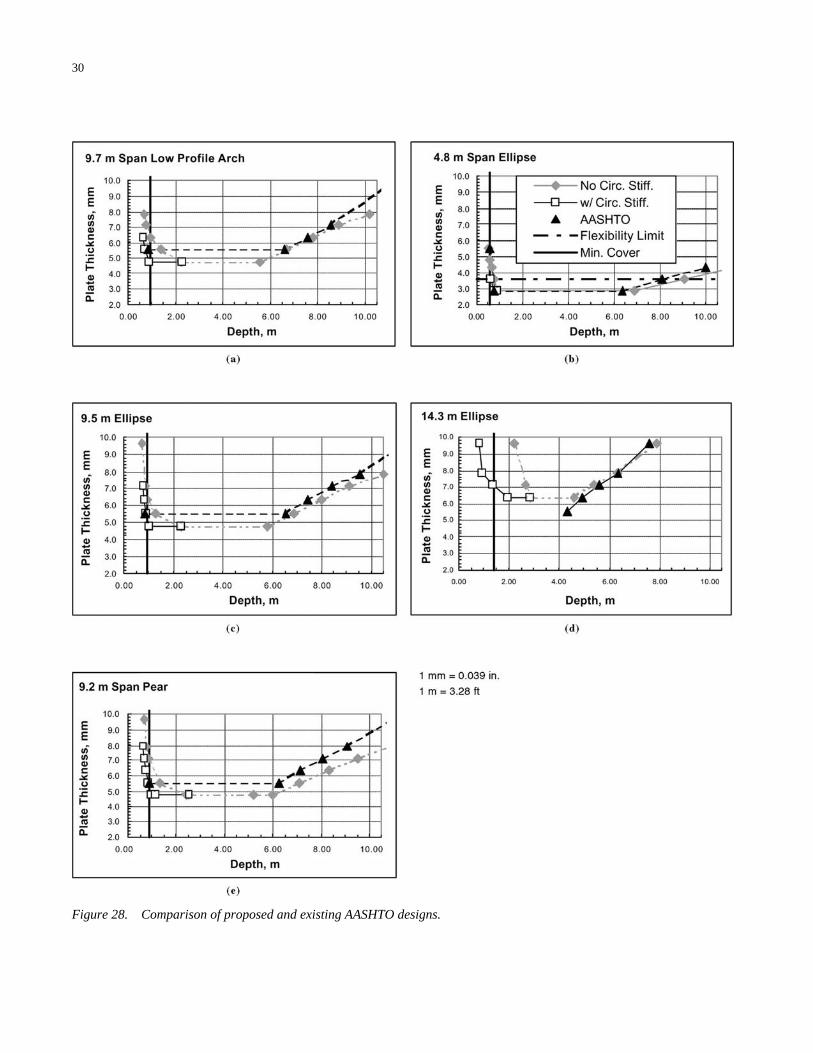
30
Figure 28. Comparison of proposed and existing AASHTO designs.
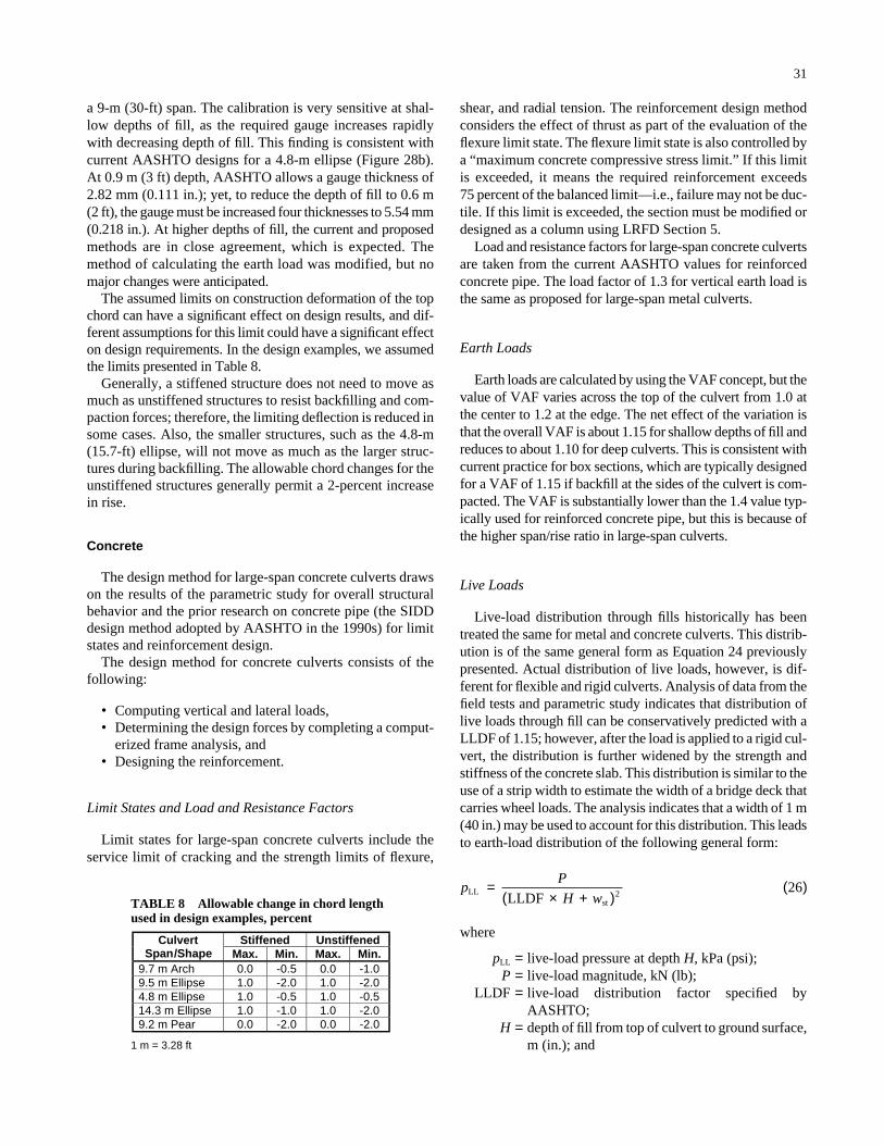
31
shear, and radial tension. The reinforcement design methodconsiders the effect of thrust as part of the evaluation of theflexure limit state. The flexure limit state is also controlled bya “maximum concrete compressive stress limit.” If this limitis exceeded, it means the required reinforcement exceeds 75 percent of the balanced limit—i.e., failure may not be duc-tile. If this limit is exceeded, the section must be modified ordesigned as a column using LRFD Section 5.
Load and resistance factors for large-span concrete culvertsare taken from the current AASHTO values for reinforcedconcrete pipe. The load factor of 1.3 for vertical earth load isthe same as proposed for large-span metal culverts.
Earth Loads
Earth loads are calculated by using the VAF concept, but thevalue of VAF varies across the top of the culvert from 1.0 atthe center to 1.2 at the edge. The net effect of the variation isthat the overall VAF is about 1.15 for shallow depths of fill andreduces to about 1.10 for deep culverts. This is consistent withcurrent practice for box sections, which are typically designedfor a VAF of 1.15 if backfill at the sides of the culvert is com-pacted. The VAF is substantially lower than the 1.4 value typ-ically used for reinforced concrete pipe, but this is because ofthe higher span/rise ratio in large-span culverts.
Live Loads
Live-load distribution through fills historically has beentreated the same for metal and concrete culverts. This distrib-ution is of the same general form as Equation 24 previouslypresented. Actual distribution of live loads, however, is dif-ferent for flexible and rigid culverts. Analysis of data from thefield tests and parametric study indicates that distribution oflive loads through fill can be conservatively predicted with aLLDF of 1.15; however, after the load is applied to a rigid cul-vert, the distribution is further widened by the strength andstiffness of the concrete slab. This distribution is similar to theuse of a strip width to estimate the width of a bridge deck thatcarries wheel loads. The analysis indicates that a width of 1 m(40 in.) may be used to account for this distribution. This leadsto earth-load distribution of the following general form:
where
pLL = live-load pressure at depth H, kPa (psi);P = live-load magnitude, kN (lb);
LLDF = live-load distribution factor specified byAASHTO;
H = depth of fill from top of culvert to ground surface,m (in.); and
pP
H wLL
stLLDF=
× +( )( )
2 26
a 9-m (30-ft) span. The calibration is very sensitive at shal-low depths of fill, as the required gauge increases rapidlywith decreasing depth of fill. This finding is consistent withcurrent AASHTO designs for a 4.8-m ellipse (Figure 28b).At 0.9 m (3 ft) depth, AASHTO allows a gauge thickness of2.82 mm (0.111 in.); yet, to reduce the depth of fill to 0.6 m(2 ft), the gauge must be increased four thicknesses to 5.54 mm(0.218 in.). At higher depths of fill, the current and proposedmethods are in close agreement, which is expected. Themethod of calculating the earth load was modified, but nomajor changes were anticipated.
The assumed limits on construction deformation of the topchord can have a significant effect on design results, and dif-ferent assumptions for this limit could have a significant effecton design requirements. In the design examples, we assumedthe limits presented in Table 8.
Generally, a stiffened structure does not need to move asmuch as unstiffened structures to resist backfilling and com-paction forces; therefore, the limiting deflection is reduced insome cases. Also, the smaller structures, such as the 4.8-m(15.7-ft) ellipse, will not move as much as the larger struc-tures during backfilling. The allowable chord changes for theunstiffened structures generally permit a 2-percent increasein rise.
Concrete
The design method for large-span concrete culverts drawson the results of the parametric study for overall structuralbehavior and the prior research on concrete pipe (the SIDDdesign method adopted by AASHTO in the 1990s) for limitstates and reinforcement design.
The design method for concrete culverts consists of thefollowing:
• Computing vertical and lateral loads,• Determining the design forces by completing a comput-
erized frame analysis, and• Designing the reinforcement.
Limit States and Load and Resistance Factors
Limit states for large-span concrete culverts include theservice limit of cracking and the strength limits of flexure,
Stiffened UnstiffenedCulvert Span/Shape Max. Min. Max. Min.
9.7 m Arch 0.0 -0.5 0.0 -1.09.5 m Ellipse 1.0 -2.0 1.0 -2.04.8 m Ellipse 1.0 -0.5 1.0 -0.514.3 m Ellipse 1.0 -1.0 1.0 -2.09.2 m Pear 0.0 -2.0 0.0 -2.0
1 m = 3.28 ft
TABLE 8 Allowable change in chord lengthused in design examples, percent
Condition BEBO ConSpan Span 9.1 m (30 ft) 11 m (36 ft) 5.4 m (16 ft) Rise 3.7 m (12 ft) 3.4 m (11 ft) 2.4 m (7.8 ft) Upper Rise 3.7 m (12 ft) 1.4 m (4.4 ft) 0.5 m (1.7 ft)
Thickness 250 mm (10 in.) Arch: 300 mm (12 in.)
Legs: 350 mm (14 in.)
Arch: 300 mm (10 in.)
Legs: 350 mm (10 in.)
Depth of Fill 0.6 m, 1.2 m, 2 m, 4 m
(2 ft, 4 ft, 6.5 ft, 13 ft)
0.6 m, 4 m
(2 ft, 13 ft) Backfill Type SW95 SW 90 Live Load Design Tandem
32
wst = distribution effect due to strength and stiffness ofconcrete slab = 1.0 m (40 in.).
In design, the denominator is also modified by the distrib-ution of the tire.
Calibration
Calibration to date has consisted of evaluation of threestructures: a 9.1-m (30-ft) span BEBO arch culvert, and 5.4-m(16-ft) and 11-m (36-ft) span ConSpan arch culverts. TheBEBO shape is the same as that tested at the University ofMassachusetts, and it is curved through its entire circumfer-ence. The ConSpan shape has a curved top slab with verticalsidewalls. Details of the culverts and analysis conditions aresummarized in Table 9.
Analyses were completed for the simplified method, whichconsisted of a frame analysis (using the computer programSTAAD) and the finite element program CANDE. Results arecompared with the University of Western Ontario (UWO)three-dimensional finite element method analyses whereappropriate. Sample calculations are included in Appendix Hof the research team’s final report.
Table 10 presents a comparison of the factored thrusts,moments, and required reinforcement for the three structuresby the simplified design method. Reinforcement design wascompleted by using the AASHTO design method for pipesections. This provides necessary strength design criteria forflexure, radial tension, diagonal tension, and service designcriteria for control of cracking.
Table 10 suggests that, for shallow depths at the crown, thereduction in live-load intensity compensates for the increasedearth load, resulting in a relatively constant factored momentfor depths up to about 2 m (6.5 ft). This is not the case for thenegative moments that increase steadily with depth.
Table 10 shows that the 11-m (36-ft) ConSpan culvertdevelops substantially higher bending moments than doesthe 9.1-m (30-ft) BEBO culvert. This trend is partly due tothe thicker section and partly due to the different shape. TheConSpan culvert has a larger radius in the top slab.
Flexure controls the reinforcement at all depths for theBEBO culvert and the 4.9-m (16-ft) ConSpan culvert. Flexure
controls the reinforcement at 0.6-m (2-ft) cover for the 11-m(36-ft) ConSpan culvert; however, at depths of 1.2, 2, and 4 m(4, 6.5, and 13 ft), the criteria for diagonal tension and crackcontrol require increases in the reinforcement area above thatrequired for flexure. At a depth of 4 m (13 ft), the analysis indi-cates that shear reinforcement is required in the leg and topslab of the ConSpan culvert. The analysis is likely somewhatconservative for these conditions. Finite element analysis isless likely to produce shear forces of this magnitude.
Table 11 compares the service forces for each load condi-tion for the BEBO and 11-m (36-ft) ConSpan arches at a depthof fill of 1.2 m (4 ft).
Tables 12–14 compare the forces from the simplifiedanalysis with the results of the UWO study and CANDE aswell as for the BEBO and 11-m ConSpan culverts. Table 12aand 12b indicates that the peak positive moments match veryclosely for all programs but that the error on the thrust issomewhat larger, although, because the thrust does not havea significant effect on the reinforcement design, this error isprobably acceptable. Table 12c and 12d indicates that thesimplified analysis predicts the negative moments and asso-ciated thrust very closely.
Table 13 indicates that the simplified analysis overpredictslive-load moments; however, this is consistent with the UWOstudy. At depths greater than 1.2 m (4 ft), the live-load con-tribution to total moment decreases rapidly.
Table 14 indicates a reasonable match between the simpli-fied analysis and CANDE for thrust and shear at the base ofthe culvert leg.
COMPREHENSIVE DESIGN METHODS
The proposed design methods for incorporation intoAASHTO specifications (Appendix F of the research team’sfinal report) are based on simplifications of culvert behavior.The goal of developing the simplified procedures was tomake simplifying assumptions that reduce the design processto a relatively straightforward procedure that does not requiresubstantial experience with culverts yet accurately predictsthe behavior of most common culvert sizes in commoninstallation conditions. Use of more sophisticated procedureswill generally result in more economical designs, and devel-
TABLE 9 Culvert and load conditions considered in calibration calculations

Crown (Peak Positive) Peak Negative (1) Moment Thrust Moment ThrustLoad Condition Manufacturer kN-m/m kN/m kN-m/m kN/m
BEBO 8.9 -12.2Self Weight ConSpan 18.9 -62.3BEBO 89 -56.0 182Vertical Earth ConSpan 65.6 -245.0 190BEBO
33.0
-22.2 44 32.6 1 Horizontal Earth ConSpan -12.2 28.5BEBO 33.0 -26.3Live Load ConSpan 44.9
1829
392632 -69.7
3548
154244
BEBO 9.6 4.1Footing Movement ConSpan 14.8
-3-4 8.9
-1-4
BEBO 62.3 -57.8Total Service Forces
ConSpan 132.0
115
174212 -340.0
260292
1. “Peak negative” is the location at which the peak negative moment occurs when all load cases are combined.
a. BEBO, 9.1 m Span
Moment and Thrust (1) Circumferential Reinforcement Requirements Peak Positive Peak Negative Asi AsoDepth M+ N+ M- N-
Thrust at Footing
Flexure Flexure Crack Diag. Tens. m kN-m/m kN/m kN-m/m kN/m kN/m mm2/m mm2/m mm2/m mm2/m
Stirrups Req’d
0.6 107 87 292 1,020 610 DNC DNC No 1.2 105 100 350 680 DNC DNC No 2.0 108
175218277 118 438
306379452
930890 800 DNC DNC No
4.0 139 452 176 686 701 1,040 1,250 DNC DNC No
b. ConSpan, 11 m Span (2)
Moment and Thrust (1) Circumferential Reinforcement Requirements Peak Positive Peak Negative Asi Aso Depth M+ N+ M- N-
Thrust at Footing
Flexure Flexure Crack Diag. Tens. m kN-m/m kN/m kN-m/m kN/m kN/m mm2/m mm2/m mm2/m mm2/m
Stirrups Req’d
0.6 185 219 321 1,500 1,650 DNC DNC No 1.2 197 277 409 1,540 2,050 DNC 2,941 No 2.0 219 350 511 1,690 2,620 2,900 5,080 No 4.0 311 583
393484608968
321394496803 803 2,710 4,510 6,180 – Yes
c. ConSpan, 4.9 m Span
Moment and Thrust (1) Circumferential Reinforcement Requirements Peak Positive Peak Negative Asi Aso Depth M+ N+ M- N-
Thrust at Footing
Flexure Flexure Crack Diag. Tens. m kN-m/m kN/m kN-m/m kN/m kN/m mm2/m mm2/m mm2/m mm2/m
Stirrups Req’d
0.0 92 73 88 133 165 991 711 DNC DNC No 4.0 130 179 180 305 363 1,340 972 DNC DNC No
DNC = Does Not Control. 1. For ConSpan structure, peak negative moment occurs in the corner, where the section is thick. Outside reinforcement is always controlled at a location lower down the leg, where the section is thinner. 2. Thrust is taken at the location associated with peak moment. 1 kN-m/m = 2.70 in.-k/ft; 1 kN/m = 5.7 k/ft
33
TABLE 11 Comparison of BEBO and ConSpan service forces, simplified analysis at1.2 m (4 ft) of cover
TABLE 10 Simplified design method: factored thrusts, moments, and reinforcing requirements
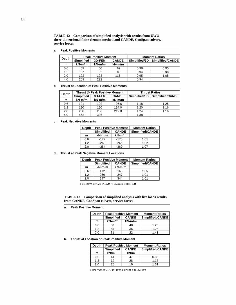
a. Peak Positive Moment
Depth Peak Positive Moment Moment Ratios Simplified CANDE Simplified/CANDE
m kN-m/m kN-m/m 0.6 48 1.25 1.2 36 1.26 2.0
604531 22 1.41
b. Thrust at Location of Peak Positive Moment
Depth Peak Positive Moment Moment Ratios Simplified CANDE Simplified/CANDE
m kN/m kN/m 0.6 47 0.88 1.2 28 1.16 2.0
413225 19 1.31
1 kN-m/m = 2.70 in.-k/ft; 1 kN/m = 0.069 k/ft
a. Peak Positive Moments
Peak Positive Moment Moment Ratios Depth Simplified 3D-FEM CANDE Simplified/3D Simplified/CANDE
m kN-m/m kN-m/m kN-m/m 0.6 60 62 0.98 0.95 1.2 92 89 0.94 0.98 2.0 128 116 0.95 1.05 4.0
5987
122209 222 0.94
b. Thrust at Location of Peak Positive Moments
Thrust @ Peak Positive Moment Thrust Ratios Depth Simplified 3D-FEM CANDE Simplified/3D Simplified/CANDE
m kN-m/m kN-m/m kN-m/m 0.6 102 95.6 1.18 1.25 1.2 150 154.0 1.20 1.16 2.0 206 219.0 1.24 1.16 4.0
121180256462 336 1.38
c. Peak Negative Moments
Depth Peak Positive Moment Moment Ratios Simplified CANDE Simplified/CANDE
m kN-m/m kN-m/m 0.6 -176 1.01 1.2 -265 1.02 2.0
-177-269-384 -360 1.07
d. Thrust at Peak Negative Moment Locations
Depth Peak Positive Moment Moment Ratios Simplified CANDE Simplified/CANDE
m kN-m/m kN-m/m 0.6 163 1.05 1.2 247 1.01 2.0
172250347 344 1.01
1 kN-m/m = 2.70 in.-k/ft; 1 kN/m = 0.069 k/ft
34
TABLE 12 Comparison of simplified analysis with results from UWO three-dimensional finite element method and CANDE, ConSpan culvert, service forces
TABLE 13 Comparison of simplified analysis with live loads resultsfrom CANDE, ConSpan culvert, service forces
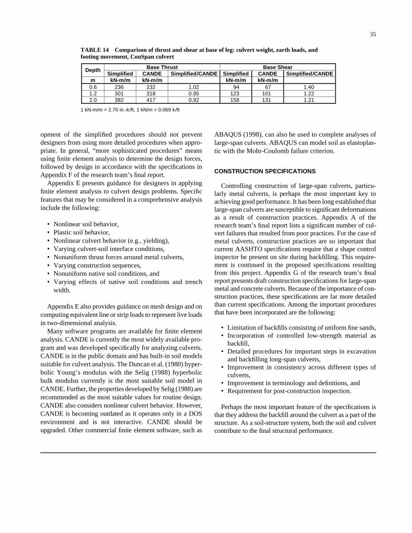
Base Thrust Base Shear Depth Simplified CANDE Simplified/CANDE Simplified CANDE Simplified/CANDE
m kN-m/m kN-m/m kN-m/m kN-m/m 0.6 236 232 94 671.2 301 318 123 1012.0 382 417
1.020.950.92 158 131
1.401.221.21
1 kN-m/m = 2.70 in.-k/ft; 1 kN/m = 0.069 k/ft
35
opment of the simplified procedures should not preventdesigners from using more detailed procedures when appro-priate. In general, “more sophisticated procedures” meansusing finite element analysis to determine the design forces,followed by design in accordance with the specifications inAppendix F of the research team’s final report.
Appendix E presents guidance for designers in applyingfinite element analysis to culvert design problems. Specificfeatures that may be considered in a comprehensive analysisinclude the following:
• Nonlinear soil behavior,• Plastic soil behavior,• Nonlinear culvert behavior (e.g., yielding),• Varying culvert-soil interface conditions,• Nonuniform thrust forces around metal culverts,• Varying construction sequences,• Nonuniform native soil conditions, and• Varying effects of native soil conditions and trench
width.
Appendix E also provides guidance on mesh design and oncomputing equivalent line or strip loads to represent live loadsin two-dimensional analysis.
Many software programs are available for finite elementanalysis. CANDE is currently the most widely available pro-gram and was developed specifically for analyzing culverts.CANDE is in the public domain and has built-in soil modelssuitable for culvert analysis. The Duncan et al. (1980) hyper-bolic Young’s modulus with the Selig (1988) hyperbolicbulk modulus currently is the most suitable soil model inCANDE. Further, the properties developed by Selig (1988) arerecommended as the most suitable values for routine design.CANDE also considers nonlinear culvert behavior. However,CANDE is becoming outdated as it operates only in a DOSenvironment and is not interactive. CANDE should beupgraded. Other commercial finite element software, such as
ABAQUS (1998), can also be used to complete analyses oflarge-span culverts. ABAQUS can model soil as elastoplas-tic with the Mohr-Coulomb failure criterion.
CONSTRUCTION SPECIFICATIONS
Controlling construction of large-span culverts, particu-larly metal culverts, is perhaps the most important key toachieving good performance. It has been long established thatlarge-span culverts are susceptible to significant deformationsas a result of construction practices. Appendix A of theresearch team’s final report lists a significant number of cul-vert failures that resulted from poor practices. For the case ofmetal culverts, construction practices are so important thatcurrent AASHTO specifications require that a shape controlinspector be present on site during backfilling. This require-ment is continued in the proposed specifications resultingfrom this project. Appendix G of the research team’s finalreport presents draft construction specifications for large-spanmetal and concrete culverts. Because of the importance of con-struction practices, these specifications are far more detailedthan current specifications. Among the important proceduresthat have been incorporated are the following:
• Limitation of backfills consisting of uniform fine sands,• Incorporation of controlled low-strength material as
backfill,• Detailed procedures for important steps in excavation
and backfilling long-span culverts,• Improvement in consistency across different types of
culverts,• Improvement in terminology and definitions, and• Requirement for post-construction inspection.
Perhaps the most important feature of the specifications isthat they address the backfill around the culvert as a part of thestructure. As a soil-structure system, both the soil and culvertcontribute to the final structural performance.
TABLE 14 Comparison of thrust and shear at base of leg: culvert weight, earth loads, andfooting movement, ConSpan culvert
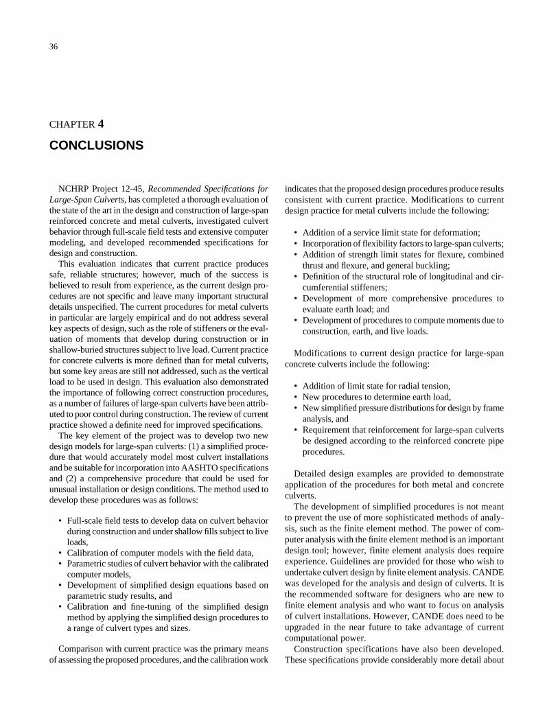
36
CHAPTER 4
CONCLUSIONS
NCHRP Project 12-45, Recommended Specifications forLarge-Span Culverts, has completed a thorough evaluation ofthe state of the art in the design and construction of large-spanreinforced concrete and metal culverts, investigated culvertbehavior through full-scale field tests and extensive computermodeling, and developed recommended specifications fordesign and construction.
This evaluation indicates that current practice producessafe, reliable structures; however, much of the success isbelieved to result from experience, as the current design pro-cedures are not specific and leave many important structuraldetails unspecified. The current procedures for metal culvertsin particular are largely empirical and do not address severalkey aspects of design, such as the role of stiffeners or the eval-uation of moments that develop during construction or inshallow-buried structures subject to live load. Current practicefor concrete culverts is more defined than for metal culverts,but some key areas are still not addressed, such as the verticalload to be used in design. This evaluation also demonstratedthe importance of following correct construction procedures,as a number of failures of large-span culverts have been attrib-uted to poor control during construction. The review of currentpractice showed a definite need for improved specifications.
The key element of the project was to develop two newdesign models for large-span culverts: (1) a simplified proce-dure that would accurately model most culvert installationsand be suitable for incorporation into AASHTO specificationsand (2) a comprehensive procedure that could be used forunusual installation or design conditions. The method used todevelop these procedures was as follows:
• Full-scale field tests to develop data on culvert behaviorduring construction and under shallow fills subject to liveloads,
• Calibration of computer models with the field data,• Parametric studies of culvert behavior with the calibrated
computer models,• Development of simplified design equations based on
parametric study results, and• Calibration and fine-tuning of the simplified design
method by applying the simplified design procedures toa range of culvert types and sizes.
Comparison with current practice was the primary meansof assessing the proposed procedures, and the calibration work
indicates that the proposed design procedures produce resultsconsistent with current practice. Modifications to currentdesign practice for metal culverts include the following:
• Addition of a service limit state for deformation;• Incorporation of flexibility factors to large-span culverts;• Addition of strength limit states for flexure, combined
thrust and flexure, and general buckling;• Definition of the structural role of longitudinal and cir-
cumferential stiffeners;• Development of more comprehensive procedures to
evaluate earth load; and• Development of procedures to compute moments due to
construction, earth, and live loads.
Modifications to current design practice for large-spanconcrete culverts include the following:
• Addition of limit state for radial tension,• New procedures to determine earth load,• New simplified pressure distributions for design by frame
analysis, and• Requirement that reinforcement for large-span culverts
be designed according to the reinforced concrete pipeprocedures.
Detailed design examples are provided to demonstrateapplication of the procedures for both metal and concreteculverts.
The development of simplified procedures is not meantto prevent the use of more sophisticated methods of analy-sis, such as the finite element method. The power of com-puter analysis with the finite element method is an importantdesign tool; however, finite element analysis does requireexperience. Guidelines are provided for those who wish toundertake culvert design by finite element analysis. CANDEwas developed for the analysis and design of culverts. It isthe recommended software for designers who are new tofinite element analysis and who want to focus on analysisof culvert installations. However, CANDE does need to beupgraded in the near future to take advantage of currentcomputational power.
Construction specifications have also been developed.These specifications provide considerably more detail about
37
the construction process than was previously available to fieldpersonnel. New aspects of the construction specificationsinclude the following:
• Limitation on use of backfills consisting of uniform finesands,
• Incorporation of controlled low-strength material asbackfill,
• Detailed procedures for important steps in excavationand backfilling long-span culverts,
• Improvement in consistency across different types ofculverts,
• Improvement in terminology and definitions, and• Requirement for post-construction inspection.
Overall, completion of this project represents a significantstep forward for the design of large-span culverts. Designersand constructors will have greatly improved tools availablefor designing and building these important components of ourhighway infrastructure.
38
REFERENCES
AASHTO, AASHTO LRFD Bridge Design Specifications, 1st ed.,Washington, DC (1994).
AASHTO, Standard Specifications for Highway Bridges, 16th ed.,Washington, DC (1996).
AASHTO, AASHTO LRFD Bridge Design Specifications, 2nd ed.,Washington, DC (1998).
ABAQUS, version 5.8. Finite Element Program, Providence, RI,Hibbitt, Karlsson, and Sorensen, Inc. (1998).
Abdel-Sayed, G., Bakht, B., and Jaeger, L. G., Soil-Steel Bridges:Design and Construction, New York, McGraw-Hill (1993) 359 pp.
Ansourian, P., “Structural Aspects of Steel Silos and Tanks.” Lecture5: Non-Axisymmetric Behaviour, Unbalanced Loading, Sydney,Australia, School of Civil and Mining Engineering, The Universityof Sydney (1981).
AWWA, AWWA Manual M45, Fiberglass Pipe Design Manual,Denver, CO (1995).
Bathe, K. J. and Bolourchi, S., “A Geometric and Material Non-Linear Plates and Shell Element.” Computers and Structures,Vol. 11 (1980) pp. 23–48.
Burns, J. Q. and Richard, R. M., “Attenuation of Stresses forBuried Cylinders.” Proceedings of Symposium on Soil-StructuredInteraction, ASTM, University of Arizona, Tucson, AZ (1964)pp. 379–392.
Byrne, P. M., Anderson, D. L., and Ahmadi, M. M., Failure of theDumont Culvert, Victoria, British Columbia, Canada, Preparedfor Ministry of Transportation and Highways, Vancouver IslandHighway and Project Management Team (1997).
Carter, J. P., PROGRAM AFENA: A General Finite Element Algo-rithm, Sydney, Australia, School of Civil and Mining Engineer-ing, The University of Sydney (1992).
Duncan, J. M., “Soil-Culvert Interaction Method for Design of MetalCulverts.” Transportation Research Record 678, Washington,DC, TRB, National Research Council (1978) pp. 53–58.
Duncan, J. M., “Behaviour and Design of Long-Span Metal Cul-verts.” Journal of Geotechnical Engineering, Vol. 105, No. GT3(1979) pp. 399–418.
Duncan, J. M., Byrne, P., Wong, K. S., and Mabry, P., Strength,Stress-Strain and Bulk Modulus Parameters for Finite ElementAnalysis of Stresses and Movements in Soil Masses, ReportUCB/GT/80-01, Berkeley, CA, Department of Civil Engineer-ing, University of California, (Aug. 1980).
El Sawy, K., Moore, I. D., and Taleb, B., “Analysis of Stability LimitStates for Long-Span Culverts.” 50th Canadian GeotechnicalConference, Ottawa, Canada, Canadian Geotechnical Society(1997) pp. 178–184.
Haggag, A. A., Structural Backfill Design for Corrugated-MetalBuried Structures, Ph.D. dissertation, Amherst, University ofMassachusetts (1989).
Heger, F. J., and McGrath, T. J., Design Method for ReinforcedConcrete Pipe and Box Sections, Vienna, VA, Prepared for theTechnical Committee of the American Concrete Pipe Associa-tion (1982).
Hoeg, K., “Stresses Against Underground Structural Cylinders.”Journal of the Soil Mechanics Division, Vol. 94, No. 4 (1968)pp. 833–858.
Howard, A. K., “Modulus of Soil Reaction Values for BuriedFlexible Pipe.” Journal of Geotechnical Engineering, Vol. 103,No. GT1 (1977) pp. 33–43.
Janbu, N., “Soil Compressibility As Determined By Oedometer andTriaxial Test.” Proceedings of the European Conference on SoilMechanics and Foundation Engineering (1963) pp. 19–25.
Katona, M. G., “Analysis of Long-Span Culverts by the Finite Ele-ment Method.” Transportation Research Record 678, Washington,DC, TRB, National Research Council (1978) pp. 59–66.
Katona, M. G. and Smith, J. M., CANDE User Manual, ReportFHWA-RD-77-6, Port Hueneme, CA, U.S. Naval Civil Engi-neering Laboratory (1976).
Kay, J. N. and Abel, J. F., “A Design Approach for Circular BuriedConduits.” International Conference on Finite Elements, Sydney,Australia (1976).
LaFave, J. M., “Large Span Precast Concrete Culvert Field Tests—Material Characterization, Crack Summary and Strain GageResults.” NCHRP Project 12-45: Limit States Design for LongSpan Culverts, Amherst, University of Massachusetts (1998).
Leonhardt, G., “Die Erdlasten be Uberschutteten Durchlassen.” DieBautechunik, Vol. 56, No. 11 (1979) pp. 361–368.
Luscher, U., “Buckling of Soil-Surrounded Tubes.” Journal ofSoil Mechanics Foundation Division, Proceedings of the Amer-ican Society of Civil Engineers, Vol. 92, No. SM6 (Nov. 1966)pp. 211–2218.
Marston, A. and Anderson, A. O., “The Theory of Loads on Pipesin Ditches and Tests on Cement and Clay Drain.” Tile and SewerPipe (1913) p. 31.
McCavour, T. C., Byrne, P. M., and Morrison, T. D., “Long-SpanReinforced Steel Box Culverts.” Transportation Research Record1624, Washington, DC, TRB, National Research Council (1998)pp. 184–195.
McGrath, T. J., “Replacing E′ with the Constrained Modulus inBuried Pipe Design.” Pipelines in the Constructed Environment,J. P. Castronovo and J. A. Clark, Eds., Reston, VA, AmericanSociety of Civil Engineers (1998).
McGrath, T. J., Selig, E. T., Webb, M. C., and Zoladz, G. V., “PipeInteraction with the Backfill Envelope.” Publication FHWA-RD-98-191, McLean, VA, U.S. Department of Transportation, FHWA(June 1999).
Moore, I. D., The Stability of Buried Tubes, PhD thesis, Sydney, Aus-tralia, School of Civil and Mining Engineering, The University ofSydney (1985).
Moore, I. D., “The elastic stability of shallow buried tubes.” Geo-technique, Vol. 37, No. 2 (1987) pp. 151–161.
Moore, I. D., “Static Response of Deeply Buried Elliptical Tubes.”Journal of Geotechnical Engineering, Vol. 114, No. 6 (1988) pp. 672–687.
Note: References cited in the body of the report and the appendixes are listed herein.
39
Moore, I. D., “Three Dimensional Response of a Shallow BuriedMetal Culvert.” 4th Int. Conf. on Short and Medium Span Bridges,Halifax, Nova Scotia, Canada (1994) pp. 95–105.
Moore, I. D., “Culverts and Buried Pipelines.” Geotechnical andGeoenvironmental Handbook, R. K. Rowe, Ed., Boston, MA,Kluwer Academic Publishers Group (2000) pp. 541–568.
Moore, I. D. and Brachman, R. W. I., “Three Dimensional Analy-sis of Flexible Circular Culverts.” Journal of Geotechnical Engi-neering, Vol. 120, No. GT10 (1994) pp. 1829–1844.
Moore, I. D. and Taleb, B., “Metal Culvert Response to Live Load-ing—Performance of Three-Dimensional Analysis.” Trans-portation Research Record 1656, Washington, DC, TRB,National Research Council (1999) pp. 37–44.
Moore, I. D., Haggag, A., and Selig, E. T., “Buckling Strength ofFlexible Cylinders with Nonuniform Elastic Support.” Interna-tional Journal of Solids and Structures, Vol. 31, No. 22 (1994)pp. 3041–3058.
Moore, I. D., Taleb, B, and El Sawy, K., “Class A Predictions forLong Span Test Culverts.” NCHRP Project 12-45, London,Canada, Geotechnical Research Centre, The University of West-ern Ontario (1997).
Musser, S. C., CANDE-89 User Manual, Report FHWA-RD-89-169, Washington, DC, FHWA (1989).
Ontario Highway Bridge Design Code, Ontario, Canada, Ministryof Transportation, Downsview, Ontario, Canada (1991).
Rotter, J. M. and Jumikis, P. T., “Non-Linear Strain DisplacementRelations for Axi-Symmetric Thin Shells.” Research ReportR563, Sydney, Australia, School of Civil and Mining Engineer-ing, The University of Sydney (1988).
Seed, R. B. and Duncan, J. M., “Soil-Structure Interaction Effectsof Compaction-Induced Stresses and Deflections.” UCB/GT/80-01, Geotechnical Engineering Report, Berkeley, CA, Universityof California (1983).
Selig, E. T., “Soil Parameters for Design of Buried Pipelines.”Pipeline Infrastructure—Proceedings of the Conference, NewYork, American Society of Civil Engineers (1988) pp. 99–116.
Selig, E. T., “Soil Properties for Plastic Pipe Installations.” G. S.Buczala and M. J. Cassidy, Eds., Buried Plastic Pipe Technol-ogy, Special Technical Publication 1093, ASTM, Philadelphia(1990) pp. 141–158.
Selig, E. T., Abel, J. F., Kulhawy, F. H., and Falby, W. E., Reviewof the Design and Construction of Long-Span Corrugated-Metal,Buried Conduits, Report No. FHWA-RD-77-131, Washington,DC, FHWA (1977).
Spangler, M. G., “Stresses in Pressure Pipelines and Protective Cas-ing Pipes.” Journal of Structural Engineering, Vol. 82, paper1054 (1956) 33 pp.
Sussmann, J., Webb, M. C., and Selig, E. T., “Soil Properties for theLarge-Span Culvert Study.” NCHRP Project 12-45, Amherst,MA, Department of Civil and Environmental Engineering, Uni-versity of Massachusetts (1998).
Taleb, B., Behaviour of Large-Span Culverts Under Earth and LiveLoadings, PhD thesis, London, Canada, Faculty of EngineeringScience, The University of Western Ontario (2000).
Taleb, B. and Moore, I. D., “Metal Culvert Response to Earth Load-ing—Performance of Two-Dimensional Analysis.” Transporta-tion Research Record 1656, Washington, DC, TRB, NationalResearch Council (1999) pp. 25–36.
Webb, M. C., Improved Design and Construction of Large-SpanCulverts, PhD dissertation, Amherst, University of Massachu-setts (1998).
Webb, M. C., Selig, E. T., and Sussmann, J., “Large Span CulvertField Test Results.” NCHRP Project 12-45, Amherst, Depart-ment of Civil and Environmental Engineering, University ofMassachusetts (1998).
Webb, M. C., Selig, E. T., and McGrath, T. J., “Instrumentation forMonitoring Large-Span Culverts.” G. N. Durham and W. A.Marr, Eds., Field Instrumentation for Soil and Rock, ASTM STP1358, American Society for Testing and Materials, West Con-shohocken, PA (1999).
White, H. L. and Layer, J. P., “The Corrugated Metal Conduit as aCompression Ring.” Proceedings of the Highway ResearchBoard, Vol. 39 (1960) pp. 389–397.
A-1
APPENDIX A
UNPUBLISHED MATERIAL
Appendixes A, F, G, and H as submitted by the researchagency in the final report are not published herein. For a lim-ited time, they are available for loan on request to theNCHRP. Their titles are as follows:
Appendix A: State-of-the-Art of Large-Span Culvert Designand Construction Practice
Appendix F: Proposed Design Specifications and Com-mentary for Large-Span Culverts
Appendix G: Proposed Construction Specifications andCommentary for Large-Span Culverts
Appendix H: Example Calculations with Simplified DesignProcedures


