35
SECTION II: RECOMMENDED CONSTRUCTION SPECIFICATIONS

SECTION II:
RECOMMENDED CONSTRUCTION SPECIFICATIONS

1 GENERALThese specifications are intended for use in
the construction of bonded repair and retrofit ofconcrete structures using fiber reinforced polymer(FRP) composites. These specifications do notinclude design aspects of FRP systems or the extentor limitations of the repair and retrofit of an existingconcrete structure.
1.1 ScopeThese specifications cover construction of
FRP systems used as externally bonded or nearsurface mounted reinforcement to enhance axial,shear, or flexural strength or ductility of a concretemember, such as column, beam, slab, or wall.
1.2 DefinitionsThe following terms used in these specifi-
cations are primarily taken from ACI 440.2R-02with some changes:
Batch—A quantity of material formed during thesame field installation in one continuous processand having identical characteristics throughout.
Bidirectional Laminate—Reinforced polymerlaminate with fibers oriented in two different direc-tions in its plane.
Binder—Resin constituent that holds together theother constituents of an FRP composite.
Bond-Critical Applications—Applications of FRPsystems for strengthening structures that rely onbond to the concrete substrate. Examples are flex-ural and shear strengthening of beams and slabs.
Catalyst—A substance that initiates a chemicalreaction and enables it to proceed under milderconditions than otherwise required and that doesnot, itself, alter or enter into the reaction. Seehardener.
II-1
C1 GENERALFRP systems may be used to increase live
load capacity of a structure, repair members thatare damaged by impact or corrosion, reduce stressesin the internal steel reinforcement, or increase duc-tility in seismic retrofit. For design issues, consultwith relevant guidelines such as ACI 440.2R-02.
C1.1 ScopeFRP systems may include externally bonded
sheets, strips, plates, and shells and near surfacemounted FRP bars and strips that are bonded insidea groove cut into the surface of concrete.
C1.2 DefinitionsThe definitions of the terms given herein
are for consistent application of these specifica-tions and may not always correspond to the ordi-nary usage of the term. For a glossary of the mostcommonly used terms related to concrete construc-tion and FRP systems, consult with ACI 116R-00,ACI 440R-96, and ACI 440.2R-02.
COMMENTARYSPECIFICATIONS
Composite—A combination of two or more mate-rials differing in form or composition on a macro-scale. The constituents retain their identities; they donot dissolve or merge completely into one another,although they act in concert. Normally, the compo-nents can be physically identified and exhibit aninterface between one another. See composite FRP.
Composite FRP—A polymer matrix, either ther-mosetting or thermoplastic, reinforced with a fiberor other material with a sufficient aspect ratio(length to thickness) to provide a discernible rein-forcing function in one or more directions. Seecomposite.
Contact-Critical Applications—Applications ofFRP systems that rely on intimate contact betweenconcrete substrate and the FRP system to functionas intended. An example is the confinement ofcolumns for seismic retrofit. In these specifica-tions, contact-critical applications are treated in thesame way as bond-critical applications. See bond-critical applications.
Creep Rupture—Failure of an FRP system result-ing from a gradual, time-dependent reduction ofcapacity due to sustained loading.
Cure—The process of causing irreversible changesin the properties of a thermosetting resin by chem-ical reaction. Cure is typically accomplished byaddition of curing agents or initiators, with or with-out heat and pressure. Full cure is the point at whicha resin reaches its specified properties. Resin isundercured if its specified properties have not beenreached.
Cure Time—The time necessary to cure a ther-mosetting resin system, thermoset-based compos-ite, or prepreg at a given temperature.
Curing Agent—A catalytic or reactive agent that,when added to resin, causes polymerization. Alsocalled hardener.
II-2
SPECIFICATIONS COMMENTARY

Debonding—A separation at the interface betweensubstrate and the reinforcing layer.
Delamination—Separation of the layers of the FRPlaminate from each other.
Development Length—The bonded distancerequired for transfer of stresses from concrete tothe FRP to develop tensile capacity of FRP.
Durability—The ability of a material to resistcracking, oxidation, chemical degradation, delam-ination, wear, or the effects of foreign object dam-age for a specified period of time, under the appro-priate load conditions and specified environmentalconditions.
Epoxy—A polymerizable thermosetting polymercontaining one or more epoxide groups, cured byreaction with phenols, anhydrides, polyfunctionalamines, carboxylic acids, or mercaptans. An impor-tant matrix resin in FRP; also used as structuraladhesive.
Fabric—Arrangement of fibers held together intwo or three dimensions. It may be woven, non-woven, knitted or stitched. Fabric architecture isthe specific description of the fibers, their direc-tions and construction.
Fiber—A general term used to refer to filamentarymaterials. The smallest unit of a fibrous material.Often, fiber is used synonymously with filament.
Fiber Content—The amount of fiber present in acomposite, usually expressed as a volume fractionor a mass fraction of the composite.
Fiber Fly—Short filaments that break off dry fibertows or yarns during handling and become air-borne, classified as nuisance dust.
II-3
SPECIFICATIONS

Fiber Reinforced Polymer (FRP) System—Composite material consisting of a polymer matrixreinforced with cloth, mat, strands, or any otherfiber form. See composite.
Filament—See fiber.
Filler—A relatively inert substance added to aresin to alter its properties or to lower cost or den-sity. Also used to term particulate additives. Alsocalled extenders.
Fire Retardant—Chemicals used to reduce thetendency of resin to burn. They can be added to theresin or coated on the surface of the FRP.
Flow—The movement of uncured resin under pres-sure or gravity loads.
Glass Transition Temperature (Tg)—The approx-imate midpoint of the temperature range overwhich a transition in material response from elas-tic to viscoelastic takes place [ASM 2001].
Hardener—Substance added to thermosettingresin to cause polymerization. Usually applies toepoxy resins.
Impregnation—The process of saturating the inter-stices of a reinforcement or substrate with a resin.
Inhibitor—A substance that retards a chemicalreaction, such as ultraviolet degradation. Also usedto prolong shelf life of certain resins.
Initiator—Chemicals, most commonly peroxides,used to initiate the curing process for unsaturatedpolyester and vinyl ester resins. See catalyst.
Laminate—One or more layers or plies of fiber,boded together in a cured resin matrix.
Lay-Up—The process of placing the FRP rein-forcing material in position for installation.
II-4
SPECIFICATIONS COMMENTARY

Lot—A quantity of material manufactured duringthe same plant production in one continuous processand having identical characteristics throughout. Inthese specifications, batch is used interchangeably.See batch.
Mat—A fibrous material for reinforced polymerconsisting of randomly oriented chopped filaments,short fibers (with or without a carrier fabric), orlong random filaments loosely held together with abinder.
Matrix—The essentially homogeneous resin orpolymer material in which the fiber system of acomposite is embedded.
Micro-Cracking—Cracks formed in compositeswhen stresses locally exceed the strength of thematrix.
MSDS—Material Safety Data Sheet.
Near Surface Mounted (NSM)—Alternativerepair system, where an FRP bar or strip is insertedand anchored into a precut groove.
Pin Holes—A small cavity, typically less than1.5 mm (0.06 in.) in diameter, that penetrates thesurface of a cured composite part.
Pitch—Petroleum or coal tar precursor base usedto make carbon fiber.
Ply—A single layer of fabric or mat.
Polyester—A thermosetting polymer synthesizedby the condensation reaction of certain acids withalcohols and subsequently cured by additionalpolymerization initiated by free radical generation.Polyesters are used as binders for resin mortars andconcretes, fiber laminates, and adhesives. Com-monly referred to as “unsaturated polyester.”
II-5
SPECIFICATIONS

Polymer—A compound formed by the reaction ofsimple molecules that permit their combination toproceed to high molecular weights under suitableconditions.
Polyurethane—A thermosetting resin prepared bythe reaction of disocyanates with polyols, poly-amides, alkyd polymers, and polyether polymers.
Postcure—Additional elevated-temperature cure toincrease the level of polymer cross linking; finalproperties of the laminate or polymer are enhanced.
Pot Life—Time that a catalyzed resin retains a vis-cosity low enough to be used in processing. Alsocalled working life.
Prepreg—A fiber or fiber sheet material contain-ing resin whose reaction has progressed to thestage where consistency is tacky. Multiple plies ofprepreg are typically cured with applied heat andpressure. Also preimpregnated fiber or sheet.
Pultrusion—A continuous process that combinespulling and extrusion for manufacturing compos-ites that typically have a constant cross-sectionalshape. The process consists of pulling a fiber mate-rial through a resin bath and then through a heatedshaping die, where the resin is cured.
Resin—A component of a polymeric system thatrequires a catalyst or hardener to polymerize orcure for use in composites. Resin often refers to themixed polymer component or matrix of the FRP.
Resin Content—The amount of resin in a lami-nate expressed as a percentage of either total massor total volume.
Roving—A number of yarns, strands, tows, or endsof fibers collected into a parallel bundle with littleor no twist.
II-6
SPECIFICATIONS COMMENTARY

Shelf Life—The length of time a material, sub-stance, product, or reagent can be stored under spec-ified environmental conditions and continue to meetall applicable specifications or remain suitable forits intended function. Also called storage life.
Structural Adhesive—A resinous bonding agentused for transferring required loads betweenadherents.
Substrate—The original concrete and any cemen-titious repair materials used to repair or replace theoriginal concrete. It can consist entirely of originalconcrete, entirely of repair materials, or of a com-bination of the two. The FRP is installed on thesurface of the substrate.
Thermoplastic—A non-cross-linked polymer capa-ble of being repeatedly softened by an increase oftemperature and hardened by a decrease in tem-perature. Examples are nylon, polypropylene, andpolystyrene.
Thermoset—A cross-linked polymer that cannotbe softened and reformed by an increase in tem-perature. Cross linking is an irreversible process;thermosets cannot be returned to a molten state.Examples are epoxy, phenolic, and vinyl ester.
Tow—An untwisted bundle of continuous fila-ments.
Unidirectional Laminate—A reinforced polymerlaminate in which substantially all of the fibers areoriented in the same direction.
Vinyl Ester—A polymerizable thermosetting resincontaining vinyl and ester components, cured byadditional polymerization initiated by free-radicalgeneration. Vinyl esters are used as binders forfiber laminates and adhesives.
II-7
SPECIFICATIONS
Viscosity—The property of resistance to flowexhibited within the body of a material, expressedin centipoises. A higher viscosity has higher resis-tance to flow.
Volatiles—Materials such as water and solvents ina resin formulation that are capable of being drivenoff as vapor.
Wet Lay-Up—A method of making a laminatesystem by applying the resin system as a liquid,when the fabric or mat is put in place.
Wet-Out—The process of coating or impregnat-ing roving, yarn, or fabric in which all voidsbetween the strands and filaments are filled withresin. It is also the condition at which this state isachieved.
Wetting Agent—A substance capable of loweringsurface tension of liquids, facilitating the wettingof solid surfaces and permitting the penetration ofliquids into the capillaries.
Witness Panel—A small FRP panel, manufacturedon site under conditions similar to the actual con-struction. The panel may be later tested to deter-mine mechanical and physical properties to confirmthe expected properties for the full FRP structure.
1.3 Recommended ReferencesThe following standards or documents are
referred to in these specifications:
ACI—American Concrete Institute• 116R-00: Cement and Concrete Terminology.• 117-90: Specifications for Tolerances for
Concrete Construction and Materials, andCommentary.
• 224.1R-93: Causes, Evaluation, and Repair ofCracks in Concrete Structures.
• 224R-01: Control of Cracking in ConcreteStructures.
II-8
SPECIFICATIONS COMMENTARY
C1.3 Recommended References

• 440R-96: State-of-the-Art Report on FiberReinforced Plastic Reinforcement forConcrete Structures.
• 440.2R-02: Guide for the Design andConstruction of Externally Bonded FRPSystems for Strengthening of ConcreteStructures.
• 503R-93: Use of Epoxy Compounds withConcrete.
• 503.4-92: Standard Specification forRepairing Concrete with Epoxy Mortars.
• 503.5R-92: Guide for the Use of PolymerAdhesives in Concrete.
• 503.6R-97: Guide for the Application ofEpoxy and Latex Adhesives for BondingFreshly Mixed and Hardened Concrete.
• 546R-96: Concrete Repair Guide.
ASTM—American Society for Testing and Materials• D3039: Test Method for Tensile Properties of
Polymer Matrix Composite Materials.• D3418: Test Method for Transition
Temperatures of Polymers by DifferentialScanning Calorimetry.
• D4541: Test Method for Pull-Off Strength ofCoatings Using Portable Adhesion Tester.
• D5687: Guide for Preparation of FlatComposite Panels with Processing Guidelinesfor Specimen Preparation.
ICBO—International Conference of BuildingOfficials• AC125: Acceptance Criteria for Concrete and
Reinforced and Unreinforced MasonryStrengthening Using Fiber-ReinforcedPolymer (FRP) Composite Systems.
• AC178: Acceptance Criteria for Inspectionand Verification of Concrete and Reinforcedand Unreinforced Masonry StrengtheningUsing Fiber-Reinforced Polymer (FRP)Composite Systems.
II-9
COMMENTARYSPECIFICATIONS
ICRI—International Concrete Repair Institute• No. 03730: Guide for Surface Preparation for
the Repair of Deteriorated Concrete Resultingfrom Reinforcing Steel Corrosion.
• No. 03732: Selecting and SpecifyingConcrete Surface Preparation for Sealers,Coatings, and Polymer Overlays.
• No. 03733: Guide for Selecting andSpecifying Materials for Repairs of ConcreteSurfaces.
1.4 TolerancesTolerances recommended by the manu-
facturer shall be followed, unless more stringentrequirements are specified in these specificationsor in the contract documents. In case of any con-flict or appearance of any conflict, the engineershall provide clarification before proceeding.
1.5 Site ConsiderationsThe contractor shall provide necessary
pathways; scaffoldings; and other means of accessto the general project site and to the specific repairarea for the personnel, equipment, and materials.All obstructions such as pipes, conduits, and wiringshall be removed at the expense of the contractor,upon approval of the engineer and after makingrecords for subsequent reinstallation by the con-tractor at the completion of the project. Plants,fences, and other obstructions that prevent accessfor repair shall be removed and, upon approval ofthe engineer, reinstalled or disposed of accordingto Section 3.4, at the expense of the contractor.
1.6 Fire ConsiderationsFire is a life safety issue with the design of
FRP systems. Most FRP systems are assumed to belost completely in a fire due to their low tempera-ture resistance.
2 SUBMITTALSThe contractor shall submit the following
documents for the engineer’s approval before start-ing the work.
II-10
C1.4 TolerancesAdherence to proper tolerances is neces-
sary to produce acceptable work. It is important toavoid accumulating tolerances. The owner mayaccept the manufacturer tolerances if appropriatetest data are shown that warrant the change basedon the unique characteristics of a particular system.
C1.5 Site ConsiderationsFRP systems can generally be installed in
most locations with very limited access and mini-mal equipment. In most applications, the impact ofthe FRP system on the existing utilities is minimal.
C1.6 Fire ConsiderationsFire resistance of FRP systems may be
improved by adding fire retardants to the resin orby coating on the surface of the FRP. Other meth-ods of fire protection may also be used.
C2 SUBMITTALS
SPECIFICATIONS COMMENTARY

2.1 Working DrawingsWorking (shop) drawings shall include the
type of FRP system, repair locations, relevantdimensions of the system, and the work plan includ-ing the necessary preparations of the existing struc-ture. The drawings must be accompanied by thedesign calculations, the MSDS, and the manufac-turer’s system data sheet identifying mechanical,physical, and chemical properties of all compo-nents of the FRP system; application guide, includ-ing the installation and maintenance procedures;and time schedule for various steps in the repairprocess. The installation procedure must clearlyidentify the environmental and substrate condi-tions that may affect the application and curing ofthe FRP system.
2.2 Quality Control/Quality Assurance PlanThe contractor shall be responsible for the
quality control of all materials and processes in theproject. The quality control and quality assurance(QC/QA) plan must be approved by the owner orits representative. It shall include specific proce-dures for personnel safety, tracking and inspectionof all FRP components prior to installation, inspec-tion of all prepared surfaces prior to FRP applica-tion, inspection of the work in progress to ensureconformity with specifications, QA samples, inspec-tion of all completed work including necessarytests for approval, repair of any defective work,and clean-up. Any part of the work that fails tocomply with the requirements of the contract doc-uments shall be rejected by the engineer and shallbe remedied or removed and replaced by the con-tractor at its own expense to be in full compliancewith the contract documents.
2.3 QualificationsThe manufacturer/supplier must be pre-
qualified by the owner or its representative foreach of its FRP systems after providing the fol-lowing necessary information:
II-11
C2.1 Working DrawingsThe necessary information for each FRP
system may be different. Shop drawings for wetlay-ups may include, for example, fiber orienta-tion, nominal thickness, aerial weight of dry fab-ric, number of layers, fiber volume or weight frac-tion, locations and lengths of lap splices, end details,and anchoring. Shop drawings for near surfacemounted FRP may include, for example, locationsand sizes of grooves and bars or strips. Shop draw-ings may also include necessary corner radii andsurface conditions of the existing structure. Thesystem data sheets may also include, for example,mix ratio, pot life, temperature-cure time data, geltime at proposed cure temperature, and acceptablehumidity and temperature ranges for mixing andapplying the resin.
C2.2 Quality Control/Quality Assurance PlanThe QC/QA program should be comprehen-
sive and cover all aspects of the FRP system. QA isachieved through a set of inspections and applicabletests to document the acceptability of the installa-tion. Details of the plan in terms of inspection, test-ing, and record keeping may be developed to matchthe size and complexity of the project. Additionalinformation regarding the necessary elements of theQC/QA plan is included in the process control man-ual that accompanies this document. The manualensures that the specifications are followed and pro-vides guidance and specific checklists for QA by theowner or its representative.
C2.3 QualificationsQualification of the manufacturer/supplier
for each of its FRP systems ensures acceptability ofthe system, as well as competence of the manufac-turer/supplier to provide it. The owner or its rep-
COMMENTARYSPECIFICATIONS

1) System data sheets and MSDSs for allcomponents of the FRP system;2) A minimum of 5 years of documentedexperience or 25 documented similar fieldapplications with acceptable reference let-ters from respective owners; 3) A minimum of 50 test data sets (total)from an independent agency approved bythe owner on mechanical properties, agingand environmental durability of the sys-tem; and 4) A comprehensive hands-on trainingprogram for each FRP system to qualifycontractors/applicators.
The contractor/applicator must be pre-qualified by the owner or its representative foreach FRP system after providing the followingnecessary information:
1) A minimum of 3 years of documentedexperience or 15 documented similar fieldapplications with acceptable reference let-ters from respective owners and 2) A certificate of completed training fromthe manufacturer/supplier for at least onefield representative who will be present onsite throughout the project.
3 STORAGE, HANDLING AND DISPOSAL
3.1 Storage
3.1.1 Storage RequirementsAll components of the FRP system must be
delivered and stored in the original factory-sealed,unopened packaging or in containers with properlabels identifying the manufacturer, brand name,system identification number, and date. Catalystsand initiators should be stored separately. All com-ponents must be protected from dust, moisture,chemicals, direct sunlight, physical damage, fire,and temperatures outside the range specified in thesystem data sheets. Any component that has been
II-12
resentative may also require the manufacturer/supplier to provide a specified number of samplesof the components and the complete FRP systemfor in-house or independent testing prior to qualifi-cation. The owner may accept the total experienceof the key personnel on similar field applications.For specific items on system data sheets, refer toSection C2.1. Test data sets may follow appropri-ate protocols such as those developed by the High-way Innovative Technology Evaluation Center(HITEC) [Reynaud et al. 1999, CERF 2001]. Thetraining program by the manufacturer/suppliershould provide hands-on experience with surfacepreparation and installation of the same FRP sys-tem for which the certificate is issued.
Qualification of the contractor/applicatorfor each FRP system ensures competence of thecontractor/applicator for surface preparation andapplication of a particular FRP system through evi-dence of appropriate training and related past expe-rience. The owner may accept the total experience ofthe key personnel on similar field applications. Thefield representative may be employed by either thecontractor/applicator or the manufacturer/supplier.
C3 STORAGE, HANDLING AND DISPOSAL
C3.1 Storage
C3.1.1 Storage RequirementsThese requirements are intended to help
preserve properties of the FRP system and main-tain the safety of the work place. The componentsmay include sheets, plates, bars, strips, resins, sol-vents, adhesives, saturants, putty, and protectivecoatings. The system identification number may bethe batch number from the factory. Typically, tem-perature in the storage area should be within10–24°C (50–75°F), unless otherwise noted on thesystem data sheet. Typically, components should be
SPECIFICATIONS COMMENTARY
stored in a condition different from that stated abovemust be disposed of, as specified in Section 3.4.
3.1.2 Shelf LifeAll components of the FRP system, espe-
cially resins and adhesives, that have been storedlonger than the shelf life specified on the systemdata sheet shall not be used and must be disposedof, as specified in Section 3.4.
3.2 HandlingAll components of the FRP system, espe-
cially fiber sheets, must be handled with careaccording to the manufacturer recommendations toprotect them from damage and to avoid misalign-ment or breakage of the fibers by pulling, separat-ing, or wrinkling them or by folding the sheets.After cutting, sheets shall be either stacked drywith separators or rolled gently at a radius notighter than 305 mm (12 in.) or as recommendedby the manufacturer.
3.2.1 Safety HazardsAll components of the FRP system, espe-
cially resins and adhesives, must be handled withcare to avoid safety hazards, including but not lim-ited to skin irritation and sensitization and breath-ing vapors and dusts. Mixing resins shall be mon-itored to avoid fuming and inflammable vapors,fire hazards, or violent boiling. The contractor isresponsible for ensuring that all components of theFRP system at all stages of work conform to thelocal, state, and federal environmental and worker’ssafety laws and regulations.
3.2.2 Material Safety Data SheetsThe MSDSs for all components of the FRP
system shall be accessible to all at the project site.Specific handling hazards and disposal instructionsshall be specified in the MSDSs.
3.2.3 Personnel and Workplace ProtectionThe contractor is responsible for providing
the proper means of protection for safety of thepersonnel and the workplace. The contractor shall
II-13
stored in a dry environment, unless an acceptablemoisture level is specified on the system data sheet.
C3.1.2 Shelf LifeProperties and reactivity of resins and
adhesives may degrade with time, temperature, orhumidity.
C3.2 HandlingFiber sheets with higher modulus fibers are
more susceptible to misalignment damages andtherefore must be handled with greater care. Dustsor residue can enter fiber sheets if not protected.Rolling precut short lengths of fiber sheets maycause damage through fiber movement and fabricshearing. Contamination of any component of theFRP system with an organic solvent may reducetensile strength and other properties of the curedlaminates.
C3.2.1 Safety HazardsConsult Chapter 9 of ACI 503R-93 for
additional information on safety hazards of epoxy.Ignition or fire in the proximity of epoxy resinscould be hazardous. Appropriate references maybe used for other types of resin such as vinyl esters.Placing carbon FRP sheets, bars, or strips near elec-trical equipment may cause short-circuit or electri-cal shock because carbon is a conductive material.Glass fibers are known to cause severe itching andskin irritation.
C3.2.2 Material Safety Data SheetsThe Code of Federal Regulations (CFR 16)
regulates the labeling of hazardous substances andincludes thermosetting-resin materials.
C3.2.3 Personnel and Workplace ProtectionSafety measures may include protective
clothing and devices (such as disposable plastic orrubber gloves, safety glasses or goggles, dust masks,
COMMENTARYSPECIFICATIONS
inform the personnel of the dangers of inhalingfumes of primer, putty, or resin and shall take allnecessary precautions against injury to personnel.The resin mixing area shall be well vented to theoutside.
3.3 Clean-UpThe contractor is responsible for the clean-
up of the equipment and the project site from haz-ardous and aesthetically undesirable FRP compo-nents using appropriate solvents, as recommendedin the system data sheet.
3.4 DisposalAny component of the FRP system that has
exceeded its shelf life or pot life or has not beenproperly stored, as specified in Section 3.1, andany unused or excess material that is deemed wasteshall be disposed of in a manner amiable to the pro-tection of the environment and consistent with theMSDS.
4 SUBSTRATE REPAIR AND SURFACEPREPARATION
The concrete substrate shall be repaired, ifnecessary, and all concrete surfaces shall be cleanedand prepared prior to installing the FRP system.
4.1 Removal of Defective Concrete All defective areas of concrete substrate
shall be removed according to ACI 546R-96 andICRI No. 03730, using appropriate equipment suchas an air- or electric-powered jack hammer or saw,at a sufficient depth of at least 12.7 mm (1/2 in.)beyond the repair area to expose sound aggregates.If any reinforcing or prestressing steel is exposed inthe process and either it is deteriorated or its bondwith the concrete is broken in the process, an addi-tional nominal depth of 19 mm (3/4 in.) or at least 6.4 mm (1/4 in.) larger than the largest aggregate inrepair material shall be cut from its underneath. Ifany deterioration is noticed in the repair area, itssource shall be located and treated to the satisfaction
II-14
safety gear respirators, fire extinguishers, and ven-tilators) depending on the FRP system, workingconditions, and the job site. Disposable gloves maydegrade in the presence of vinyl esters and solventsif not specifically designed for use with the FRPsystem.
C3.3 Clean-UpThe contractor may additionally consult
with the prevailing environmental protection andhealth agencies for proper clean-up of the projectsite. Some clean-up solvents may be flammable.
C3.4 DisposalPot life depends on the system, mixed quan-
tity, and ambient temperature. The contractor mayalso consult the prevailing environmental protec-tion and health agencies for proper disposal of FRPcomponents. Unused mixed primer, putty, or resinshould be allowed to harden in their containersbefore disposal.
C4 SUBSTRATE REPAIR AND SURFACEPREPARATION
A clean and sound concrete substrate isessential to the effectiveness of the FRP system inachieving the design strength and the intendeddesign objectives.
C4.1 Removal of Defective Concrete Defects may include loose and broken
debris or delaminated and spalled sections of con-crete, voids and honeycombs, and deteriorated con-crete. Defects in the concrete substrate can compro-mise the integrity of the FRP system. Any attemptat covering the deteriorated (carbonated or chloridecontaminated) concrete with the FRP system with-out correcting the source of deterioration may bedetrimental to the effectiveness of the repair. Inves-tigations to date have shown that placement ofexternally bonded FRP, especially when used forfull confinement, may arrest cracking of concreteand slow down the rate of corrosion of steel rein-forcement, but does not stop or reverse the cor-
SPECIFICATIONS COMMENTARY
of the engineer prior to restoring the section. Uponremoving defective concrete, and before restoringthe section, the substrate shall be cleaned fromany dust, laitance, grease, oil, curing compounds,impregnations, foreign particles, wax, and otherbond-inhibiting materials, as per Section 4.4.6.
4.2 Repair of Defective ReinforcementAll defective reinforcement shall be repaired
according to ICRI No. 03730 and to the satisfac-tion of the engineer. FRP systems shall not beapplied to concrete suspected of containing cor-roded reinforcement. Corroded or otherwise defec-tive reinforcement that is to be supplemented shallbe cleaned and prepared thoroughly by abrasivecleaning to a near white appearance. Damagedreinforcement that needs to be replaced shall be cutat sufficient length, according to the contract doc-uments and the approval of the engineer, to ensurefull section and sound material in the remainingportion. Splice for the ruptured or cut reinforcingor prestressing steel shall be provided at sufficientlength, according to the contract documents andapproval of the engineer.
4.2.1 Mechanical AnchorageMechanical anchorage of the repair mater-
ial with the substrate shall be placed if specified inthe contract documents. Anchors shall be securedin place by tying to other secured bars and shall notprotrude outside concrete surface. If that is notpossible, the concrete surface shall be built up tocover the protrusions.
4.3 Restoration of Concrete Cross SectionThe area of removed concrete substrate,
and any void larger than 12.7 mm (1/2 in.) in diam-eter and depth, shall be filled with repair materialthat conforms to ICRI No. 03733. The repair mate-rial shall have a compressive strength equal to orgreater than that of the original concrete, but noless than 31 and 38 MPa (4,500 and 5,500 psi) at 7 and 28 days, respectively. The design mix for allrepair materials shall be approved by the engineer.
II-15
rosion process [Harichandran and Baiyasi 2000,Sohanghpurwala and Scannell 1994]. Precautionsmay be necessary in cases of carbonation, alkali-silica reactivity (ASR), or reactive aggregate.
C4.2 Repair of Defective ReinforcementDefects in the reinforcement may include
section loss or rupture due to impact or corrosion.Any attempt at covering the deteriorated sectionwith FRP without arresting the corrosion processmay be detrimental to the entire repair because ofthe expansive forces associated with corrosion. Ifnot treated properly, repair in one section may leadto an accelerated corrosion in an adjacent section.The exposed steel may be treated by applying cor-rosion inhibitors prior to restoring the section. Theowner may require other treatment forms for cor-roded steel or placement of sensors to monitor thecorrosion process. The splice detail is intended toprovide strength and ductility in both longitudinaland transverse directions in case the FRP system islost due to fire, vandalism, or any other cause.
C4.2.1 Mechanical AnchorageMechanical steel or plastic anchorage en-
sures adequate bond with the existing cross sec-tion, where new concrete patch material is placed.A grid of 102 mm × 102 mm (4 in. × 4 in.) with aminimum embedment depth of 38 mm (11/2 in.) isusually adequate. If the anchors protrude outsidethe concrete surface, they may damage fibers usedin the FRP system.
C4.3 Restoration of Concrete Cross SectionThe repair material may be an approved
polymer- or latex-modified mortar/concrete or anapproved factory-bagged mortar/concrete patchingmaterial of equal characteristics. It is recommendedthat the manufacturer be consulted on the compati-bility of the repair material with the FRP system. Atlocations where the size of the voids or other con-straints necessitate that prebagged mortar/concretenot be used, a Class III latex-modified concrete
COMMENTARYSPECIFICATIONS

The bond strength of the repair material to theexisting concrete shall be a minimum of 1.4 MPa(200 psi) in the pull-off test according to ASTMD4541. The concrete substrate and the exposedreinforcing or prestressing steel shall be clean,sound, and free of surface moisture and frostbefore restoring the section. Before placement ofpatching materials, a water-based epoxy cementi-tious bonding agent shall be applied to concreteand exposed reinforcement. Also, cracks withinsolid concrete in the substrate shall be stabilizedusing epoxy injection methods, as specified in Sec-tion 4.4.3. If the water leak through cracks or con-crete joints is significant, water protection and awater conveyance and weep holes shall be pro-vided before restoring the section. The repair mate-rial shall be cured a minimum of 7 days beforeinstalling the FRP system unless its curing andstrength are verified by tests.
4.4 Surface PreparationAll necessary repair and restoration of a
concrete section shall be approved by the engineerprior to surface preparation. In these specifications,contact-critical applications are treated in the sameway as bond-critical applications. An adhesivebond with adequate strength shall always be pro-vided between FRP and concrete. Surface prepara-tion shall also promote continuous intimate contactbetween FRP and concrete by providing a clean,smooth, and flat or convex surface. Surface prepa-ration for near surface mounted FRP bars or stripsis specified in Section 4.4.4. Surface preparationfor FRP shell systems where grout is pumped intothe gap between the shell and the existing columnsurface is specified in Section 4.4.5. All surfacepreparations shall be approved by the engineerbefore installing the FRP system.
4.4.1 Surface Grinding All irregularities, unevenness, and sharp
protrusions in the surface profile shall be grindedaway to a smooth surface with less than 0.8-mm(1/32-in.) deviation. Disk grinders or other similardevices shall be used to remove stain, paint, or any
II-16
may be used, as approved by the engineer. No form-work is necessary for small voids, where repairmaterials may be placed by hand and troweled tomatch the original section. Formwork for largerareas may be built around the damaged area toensure that the restored section is smooth and uni-form and that it conforms to the original shape ofthe section. The instruction for most patchingmaterials specifies a bonding agent, often a dilutedmixture of the patching mix rubbed into the con-crete. Curing time depends on the type of patchingmaterials.
C4.4 Surface PreparationSurface roughness has a significant effect
on the bond between the FRP system and concrete[Shen et al. 2002]. Surface preparation depends onthe type of application and the type of FRP system.Even though bond may not be structurally neces-sary for contact-critical applications such as con-finement of columns, it would help improve dura-bility of the structure. Many applications of columnwrapping occur in aggressive environments. Anydebonding between FRP and concrete that mayresult from less stringent criteria could lead to sig-nificant damage during freeze-thaw cycles.
C4.4.1 Surface Grinding Consult with the ACI 546R-96 and ICRI
No. 03730 for grinding of concrete surfaces andfor ensuring proper surface preparation. Vacuumcleaning could help reduce the dusts in environ-mentally sensitive areas.
SPECIFICATIONS COMMENTARY
other surface substance that may affect the bond.Voids or depressions with diameters larger than12.7 mm (1/2 in.) or depths greater than 3.2 mm (1/8 in.), when measured from a 305-mm (12-in.)straight edge placed on the surface, shall be filledaccording to Section 4.4.5.
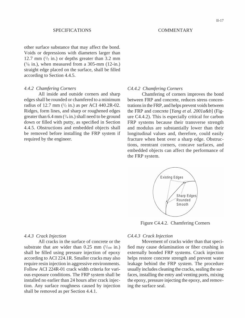
4.4.2 Chamfering CornersAll inside and outside corners and sharp
edges shall be rounded or chamfered to a minimumradius of 12.7 mm (1/2 in.) as per ACI 440.2R-02.Ridges, form lines, and sharp or roughened edgesgreater than 6.4 mm (1/4 in.) shall need to be grounddown or filled with putty, as specified in Section4.4.5. Obstructions and embedded objects shallbe removed before installing the FRP system ifrequired by the engineer.
4.4.3 Crack InjectionAll cracks in the surface of concrete or the
substrate that are wider than 0.25 mm (1/100 in.)shall be filled using pressure injection of epoxyaccording to ACI 224.1R. Smaller cracks may alsorequire resin injection in aggressive environments.Follow ACI 224R-01 crack width criteria for vari-ous exposure conditions. The FRP system shall beinstalled no earlier than 24 hours after crack injec-tion. Any surface roughness caused by injectionshall be removed as per Section 4.4.1.
II-17
C4.4.2 Chamfering CornersChamfering of corners improves the bond
between FRP and concrete, reduces stress concen-trations in the FRP, and helps prevent voids betweenthe FRP and concrete [Yang et al. 2001a&b] (Fig-ure C4.4.2). This is especially critical for carbonFRP systems because their transverse strengthand modulus are substantially lower than theirlongitudinal values and, therefore, could easilyfracture when bent over a sharp edge. Obstruc-tions, reentrant corners, concave surfaces, andembedded objects can affect the performance ofthe FRP system.
COMMENTARYSPECIFICATIONS
E xisting Edges
S harp EdgesR ounded S m ooth
C4.4.3 Crack InjectionMovement of cracks wider than that speci-
fied may cause delamination or fiber crushing inexternally bonded FRP systems. Crack injectionhelps restore concrete strength and prevent waterleakage behind the FRP system. The procedureusually includes cleaning the cracks, sealing the sur-faces, installing the entry and venting ports, mixingthe epoxy, pressure injecting the epoxy, and remov-ing the surface seal.
Figure C4.4.2. Chamfering Corners
4.4.4 Grooves for Near Surface Mounted FRPA groove with dimensions specified in the
contract documents shall be made in the concrete,where the FRP bar or strip is to be placed. Careshall be taken to avoid local fracture of the con-crete surrounding the groove. The groove in whichFRP is to be placed shall be free of loose, unsound,or bond-inhibiting materials such as oil, efflores-cence, or moisture. All obstructions and embeddedobjects shall be removed from the groove area uponapproval of the engineer.
4.4.5 Surface ProfilingAfter surface grinding, any remaining
unevenness in the surface greater than that specifiedin Section 4.4.3, including out-of-plane variations,fins, protrusions, bug holes, depressions voids, androughened corners, shall be filled and smoothedover using putty made of epoxy resin mortar orpolymer cement mortar with strength equal to orgreater than the strength of the original concrete.The patching material shall be cured a minimum of7 days before installing the FRP system unless itscuring and strength are verified by tests.
4.4.6 Surface CleaningSubstrate concrete and finished surface of
concrete shall be cleaned to the approval of theengineer. Cleaning shall remove any dust, laitance,grease, oil, curing compounds, wax, impregna-tions, stains, paint coatings, surface lubricants, for-eign particles, weathered layers, or any other bond-inhibiting material. If power wash is used, thesurface shall be allowed to dry thoroughly beforeinstalling the FRP system. The cleaned surfaceshall be protected against redeposit of any bond-inhibiting materials. Newly repaired or patchedsurfaces that have not cured a minimum of 7 daysshall be coated with a water-based epoxy paint orother approved sealers.
5 INSTALLATION OF FRP SYSTEMThis section specifies general installation
procedures for three types of FRP systems: wetlay-up, precured, and near surface mounted. Spe-
II-18
C4.4.4 Grooves for Near Surface Mounted FRPIt is recommended to first examine the
existing conditions to assess the quality of the con-crete substrate, identify potential obstructions, andverify the dimensions and geometries shown in thecontract documents. The groove is often made usinga grinder or concrete saw with a suitable blade.Embedded obstructions and objects can affect theperformance of the FRP system.
C4.4.5 Surface ProfilingConsult the ACI546R and ICRI Guideline
No. 03730 for surface profiling. Surface profile ofthe concrete substrate may provide an open rough-ened texture for precured FRP shell systems, wheregrout is pumped into the space between the shelland the existing column surface. Curing timedepends on the type of patching materials.
C4.4.6 Surface CleaningThis section relates to surface cleaning for
the substrate after removal of defective concreteand prior to restoring the concrete section, as spec-ified in Section 4.1. It also relates to surface clean-ing of the finished surface of concrete beforeinstalling the FRP system. Cleaning may be per-formed with blast cleaning, an air blower, pressurewashing, or other equivalent means. Clean wipingrags may also be used for removing any dust thatmay have been generated on the concrete surfaceduring the grinding operation. Vacuum cleaningcould help reduce the dusts in environmentallysensitive areas.
C5 INSTALLATION OF FRP SYSTEMContract documents provide specific pro-
cedures for the specific type of FRP system. Other,less common FRP systems, such as dry lay-up and
SPECIFICATIONS COMMENTARY

cific procedures for installing FRP systems mayvary slightly for each system and manufacturer.
5.1 Environmental Conditions for InstallationEnvironmental conditions shall be exam-
ined before and during installation of the FRP sys-tem to ensure conformity to the contract documentsand manufacturer’s recommendations. Do not applyprimers, putty, saturating resins, or adhesives oncold, frozen, damp, or wet surfaces. Ambient andconcrete surface temperatures shall be within10–35°C (50–95°F), unless specified by the manu-facturer. Moisture level on all contact surfaces shallbe less than 10% at the time of installation of theFRP system, as evaluated according to ACI 503R-93. Moisture restrictions may be waived for resinsthat have been formulated for wet applications.
5.1.1 Moisture Vapor TransmissionApplication of bonded FRP systems shall
not proceed if any moisture vapor transmission ispresent. Concrete dryness is necessary when usingelevated temperature cure. Any bubble that devel-ops from moisture vapor transmission can effec-tively be injected with the same adhesive materialused for the FRP system following the procedurespecified in Section 7.2.
5.1.2 Applications in Inclement WeatherWhen inclement weather does not allow
installation of the FRP system, as specified in Sec-tion 5.1, auxiliary measures may be employed to cor-rect the conditions. An auxiliary heat source may beused in cold weather to raise the ambient and con-crete surface temperatures to acceptable levels, asrecommended by the manufacturer, but not higherthan the glass transition temperature (Tg). Pressur-ized air may be used to dry the surface dampness.
5.2 ShoringRepaired members shall be shored tem-
porarily with conventional methods, if specified in
II-19
machine-applied or automated, are not included inthese specifications.
C5.1 Environmental Conditions for InstallationMoisture may hinder adhesion of the primer
and resin. Work may be postponed if adverseweather, rain, or dew condensation is anticipated.Although moisture primarily affects the polymersand concrete surface, it may also collect on the sur-face of the fiber sheets if not stored properly, asspecified in Section 3.1.1. Moisture on fiber sheetscan cause problems with wet-out and cure of thesystem. Surface moisture may be measured using amortar moisture meter or an absorbent paper. Coldweather may cause improper curing of the resin andsaturation of fibers, compromising the integrity ofthe FRP system.
C5.1.1 Moisture Vapor TransmissionThis section applies only to the conditions
at the time of construction and not to those thatshould be addressed in the design process. Mois-ture vapor transmission from the concrete surfacethrough uncured resin may cause air pockets andsurface bubbles, compromising the bond betweenthe FRP system and the concrete. These effectshave primarily been observed in wet lay-ups, butare not excluded from other FRP systems.
C5.1.2 Applications in Inclement WeatherDifferent heating systems such as spot-
lights, electrical heaters, infrared heating, and heat-ing blankets may be used. Electrical conductivityof carbon fibers may be used to apply a current,thereby providing fast in-situ curing in about 3 hours [CEB-FIP 2001]. The maximum elevatedtemperature depends on the system used. This pro-cedure, however, is not yet widely accepted asproviding a uniform and consistent cure profile.
C5.2 ShoringIn most applications, the FRP system may
be applied while the structure is in service. Shoring
COMMENTARYSPECIFICATIONS
contract documents, or required by the engineerfor safety. Shoring shall not be removed until theFRP system has fully cured and gained its designstrength, as recommended by the manufacturer andapproved by the engineer.
5.3 EquipmentThe contractor shall provide all necessary
equipment in sufficient quantities and in clean oper-ating conditions for continuous uninterrupted FRPinstallation.
5.4 Application of Wet Lay-Up FRP SystemsThis section specifies the necessary mea-
sures for installing wet lay-up systems using dry orprepreg fiber sheets and saturants.
5.4.1 Mixing of Resin ComponentsAll resin components, including the main
agent and hardener, shall be mixed at the proper tem-perature using the appropriate weight ratio and for aduration specified by the manufacturer until thor-ough mixing with uniform color and consistency isachieved. Resins shall not be diluted with anyorganic solvents such as thinner. Manual stirring andsmall electrically powered mixing blades areallowed. Resin shall be mixed in quantities suffi-ciently small to ensure that it can be used within itspot life. Any mixed resin that exceeds its pot life orbegins to generate heat or show signs of increasedviscosity shall not be used and shall be disposed ofaccording to Section 3.4. Mixing of some resins maybe accompanied by noxious fumes. Precautions mustbe taken, as specified in Section 3.2.1, regarding theresin’s impact on the environment, including emis-sion of volatile organic compounds and toxicology.
5.4.2 Primer and PuttyA primer coat is generally required in all
available FRP systems. Apply one or two coats ofprimer on the concrete surface to penetrate its openpores. Ambient and concrete surface temperaturesmust be within the range specified in Section 5.1.The putty, if used in the FRP system, shall beapplied as soon as the primer becomes tack free or
II-20
may be provided to either support the existingstructure prior to repair or reduce the structure’sinitial deflections prior to strengthening. Shoringmay also be used to induce an initial camber in thesystem, thereby stressing the FRP system.
C5.3 EquipmentThe equipment may vary for different FRP
systems and may include resin impregnators,rollers, sprayers, and lifting and positioning devices.
C5.4 Application of Wet Lay-Up FRP SystemsWet lay-up systems may alternatively be
applied using special equipment (a saturator) toautomate and speed up the process.
C5.4.1 Mixing of Resin ComponentsThe term resin is a generic denomination
used to identify all polymers employed in wet lay-up systems. Depending on its function, resin ismore specifically identified as primer, putty, andsaturant. Not all FRP systems use putty. Excessiveagitation, when using electrically powered mixers,may cause froth and bubbles that can be entrappedas voids in the resin. Resin components are oftencontrasting colors; hence, full mixing is achievedwhen color streaks are eliminated. The stoichiome-try of the resin will not be met unless resin solids atthe bottom of the container are completely mixed.Pot life of resin depends on the resin type and theambient temperature. Viscosity of a mixed resin thathas exceeded its pot life will continue to increase,adversely affecting the resin’s ability to penetratethe concrete surface or saturate the fiber sheet.
C5.4.2 Primer and PuttyPrimer may be applied using a clean roller
or brush. The primer, when applied uniformly,helps hatch and strengthen the most external layerof concrete and improves the bond between theconcrete substrate and the FRP system. The rate ofsurface coverage of primer is typically listed in thesystem data sheet. Not all FRP systems use putty.
SPECIFICATIONS COMMENTARY

is not sticky to the fingers. The putty shall beapplied within 7 days after primer application; oth-erwise, the primer-coated surface shall be rough-ened with sandpaper or a similar tool. The result-ing surface shall be cleaned according to Section4.4.6 before applying the putty. Apply a thin coat ofputty in one or two layers, and smooth over the sur-face to fill in any small voids, cracks, or unevenareas. Any swelling on the surface after applying theputty shall be corrected to meet surface profile asspecified in Section 4.4.5. The surfaces of primerand putty shall be protected from dust, moisture, andany other contaminants before applying the FRP.
5.4.3 SaturantThe first coat of saturating resin, saturant,
shall be uniformly applied as an undercoat to alllocations on the concrete surface where the FRPsystem is to be installed. The saturant shall havesufficiently low viscosity to ensure full impregna-tion of the fiber sheets prior to curing. To maintainproper viscosity of the saturant, the ambient andconcrete surface temperatures must be within therange specified in Section 5.1. Any mixed saturantthat exceeds its pot life shall be disposed of accord-ing to Section 3.4.
5.4.4 Applying Fiber Sheet and SaturantUpon uniformly applying the first layer of
saturant as an undercoat, the fiber sheet previouslycut to the length specified in the contract docu-ments shall be installed in place and gently pressedonto the wet saturant. Any entrapped air betweenthe fiber sheet and the concrete surface shall bereleased or rolled across the sheet in the directionparallel to the fibers while allowing the resin toimpregnate the fibers and achieve intimate contactwith the substrate. Rolling perpendicular to thefiber direction is not allowed. In bidirectional fab-rics, rolling shall be initially in the fill direction endto end and then in the warp direction. Sufficientsaturant shall be applied on top of the fiber sheet,as overcoat, to ensure full saturation of the fibers.Undercoat, fiber sheets, and overcoat shall beapplied with no interruption.
II-21
The primary function of the putty, if used, is tosmoothen the concrete surface. The putty may beapplied using a clean trowel or spatula or any othersuitable tool. Adding silicate sand to the putty mayimprove stability and prevent swelling.
C5.4.3 SaturantThe resin that impregnates the fibers is the
key component to form the FRP laminate thatrepairs or retrofits the concrete member. The rateof coverage of the resin is listed on the system datasheet, but generally depends on the type of resin,the ambient temperature, and the porosity of con-crete surface. The typical rate of application isabout 4.9 kg/m2 (0.1 lb/ft2).
C5.4.4 Applying Fiber Sheet and SaturantThis installation procedure is for a single
fiber sheet or the first fiber sheet or ply in a multiple-ply application. Alternatively, the fiber sheet may beseparately impregnated using a resin-impregnatingmachine before being placed on the concrete sur-face. For ease of handling and to avoid wrinkling,fiber sheets are typically cut in segments shorterthan 4.6- to 6.1-m (15- to 20-ft) lengths. Metal-serrated rollers are often used to force resin betweenfibers and to remove entrapped air. However, whenused with excessive force, these rollers may causefracture of the fibers. Rolling perpendicular to thefiber direction may misalign or damage the fibers.
COMMENTARYSPECIFICATIONS
5.4.5 Multiple-Fiber Plies In multiple-ply installations, the sequence
specified in Section 5.4.4 shall be repeated for eachadditional fiber sheet. The amount of resin overcoatfor intermediate plies is approximately 15–20%greater than a single-ply installation because thesaturant serves as overcoat for the applied ply andundercoat for the next ply. Follow the contractdocuments for the fiber orientation and ply stack-ing sequence. Each ply shall be applied before theonset of complete gelation of the previous layer.The number of plies that can be applied in a singleday shall be based on the manufacturer’s recom-mendation and the approval of the engineer. Mul-tiple plies can also be applied in several days. Whenprevious layers are cured, interlayer surface prepa-ration, such as light sanding and filling with putty,may be required, as specified in Section 5.4.2.
5.4.6 OverlappingA lap joint shall be constructed when an
interruption occurs in the direction of the fibers. Thelength of the lap splice shall be as specified by thecontract documents, but must be at least 152 mm (6 in.). Staggering of lap splices on multiple pliesand adjacent strips shall be required unless per-mitted by contract documents. No lap joint is nec-essary in the transverse direction unless specifiedin the contract documents.
5.4.7 Alignment of FRP MaterialsThe fiber plies shall be aligned on the struc-
tural member according to the contract documents.Any deviation in the alignment more than 5°(approximately 87 mm/m or 1 in./ft) is not accept-able, as specified in Section 6.3. Once installed, thefibers shall be free of kinks, folds, and waviness.
5.4.8 Anchoring of FRP SheetsAnchoring of FRP sheets to the concrete
substrate shall follow the method specified in thecontract documents or approved by the engineer.When using mechanical clamps and fasteners, care
II-22
C5.4.5 Multiple-Fiber Plies Some repair and retrofit applications may
require more than a single-fiber ply to be installedby wet lay-up. The waiting time between pliesdepends on the type of resin, the type of fiber sheet,and the ambient temperature. It is good practice towait for the resin to fully impregnate the fibers toavoid forming air pockets. The rate of coverage ofthe resin overcoat is listed on the system data sheet,but generally depends on the type of resin and fibersand the ambient temperature. The typical rate ofapplication is about 2.4 kg/m2 (0.05 lb/ft2). Appli-cation of too many plies in a single day may resultin slippage or separation because of the self-weightof fiber sheets. The number of plies that can beapplied in a single day depends on the ambient tem-perature, the weight of the fiber sheet, and whetherthe repair is overhead or on a vertical surface.
C5.4.6 OverlappingWhen the length of the sheet to be installed
exceeds the length suggested by the manufacturerfor proper installation, lap jointing becomes nec-essary. Lap splice length depends on the type ofresin and fibers [Yang and Nanni 2002, Belarbi et al. 2002]. For large coverage areas, it is recom-mended that all lap joints in the longitudinal direc-tion of fibers be made in a single day. Transverse lapjoints, if necessary, may be made in several days.
C5.4.7 Alignment of FRP MaterialsPerformance of a unidirectional FRP sys-
tem depends heavily on fiber orientation andstraightness. Misalignment may occur because ofimproper rolling or wrong placement of fiber sheets.Fiber misalignment is known to affect the strengthmore significantly than the elastic modulus [Yanget al. 2002].
C5.4.8 Anchoring of FRP SheetsAnchoring of fiber sheets helps prevent
delamination failure of the FRP system. Differentmethods can be employed to anchor the fiber sheets.When possible, U-wraps may provide additional
SPECIFICATIONS COMMENTARY
shall be taken to avoid damage to the FRP systemor to the concrete substrate. Precautions shall betaken when steel fasteners are used for carbon FRPto avoid galvanic corrosion. FRP anchors shall besufficiently embedded in concrete.
5.4.9 Stressing ApplicationsStressing of FRP systems shall follow the
method specified in contract documents. Activeend anchorages shall be used for linear prestress-ing. For circular prestressing of wet lay-up sys-tems, the gap left between the FRP system and theconcrete column shall be filled using expansivemortar or pressure injection of epoxy grout, asspecified in Section 5.5.4.
5.5 Application of Precured FRP SystemsInstallation of precured FRP systems is
generally similar to that of single-ply wet lay-up.Surface preparation of the concrete substrate shallprovide an open roughened texture.
5.5.1 Application of AdhesiveApply the adhesive uniformly onto all sur-
face areas of the concrete substrate where the pre-cured FRP system is to be installed. Thickness andviscosity of the adhesive layer shall be according tothe manufacturer’s recommendations. Ambient andconcrete surface temperatures must be within therange specified in Section 5.1 prior to applying theadhesive. Any mixed adhesive that exceeds its potlife shall be disposed of, as specified in Section 3.4.
5.5.2 Placement of Precured SystemPrecured FRP systems shall be cleaned, cut
to the length specified in the contract documents,and placed into the wet adhesive within the pot lifeof the adhesive. Entrapped air between laminateand concrete shall be released, and excess adhesiveshall be removed. Do not disturb the applied FRPsystem before the adhesive fully cures.
II-23
anchorage against premature delamination of theFRP system.
C5.4.9 Stressing ApplicationsStressing and active confinement with a
glass FRP system is NOT recommended becauseof concerns related to creep rupture. The prestrainin carbon should be limited to 50% of the ultimatestrain due to damage tolerance concerns with uni-directional carbon FRP.
C5.5 Application of Precured FRP SystemsPrecured FRP systems consist of laminates
in the form of plates, strips, open grid forms, orshells. These systems are typically installed withan adhesive resin.
C5.5.1 Application of AdhesiveAdhesives may be applied with a spatula or
any other suitable tool. The rate of coverage of theadhesive is listed on the system data sheet, but gen-erally depends on the type of resin, the ambienttemperature, and the porosity of concrete surface.The typical rate of application is about 4.9 kg/m2
(0.1 lb/ft2). The adhesive is not necessary when anintentional gap is left between the concrete surfaceand the FRP shell to be later filled with grout, asspecified in Section 5.5.4.
C5.5.2 Placement of Precured SystemSince there are a number of different pre-
cured systems, it is important to follow the manu-facturer’s recommendations on the timing andsequence of stacking, overlap and banding, hori-zontal and vertical joints, staggering of splices, andoverlap and butt joints. The use of a dust mask isrecommended when cutting precured FRP systems.
COMMENTARYSPECIFICATIONS
5.5.3 Anchoring of Precured SystemAnchoring of precured systems is typically
the same as anchoring for the FRP sheets, as spec-ified in Section 5.4.8.
5.5.4 Grouting of Precured ShellsPrecured shells around concrete columns
shall be grouted no less than 24 hours after instal-lation. Pressure grouting shall follow the contractdocuments and the manufacturer’s recommenda-tions. The grout shall have a shrinkage strain ofless than 0.0005 and a compressive strengthgreater than 27.6 MPa (4,000 psi).
5.5.5 Stressing ApplicationsInstallation of prestressed FRP systems
requires a moveable anchorage, which usuallyconsists of gluing the FRP laminate terminationbetween two steel plates held in place by screws.After curing the moveable anchorage, the fixedanchorage at the other end of the member shall beinstalled and the FRP laminate shall be gluedbetween a steel plate and the concrete surface. Fas-ten the steel plate to the concrete surface usinginserts. The fixed anchorage must be cured beforethe FRP laminate can be stressed. Install anotherfixed anchorage on the concrete surface at the otherend of the member using an insert. Once the twofixed anchors have been installed, the system isready for stressing with hydraulic jacks. During theprestressing process, an epoxy gel is spread uni-formly on the entire concrete surface where thelaminate has contact. The thickness of the epoxygel shall follow the manufacturer’s recommenda-tion. Any entrapped air shall be released by press-ing on the FRP. After the epoxy gel has cured, themoveable anchor is removed and the laminate iscut. Both fixed anchors remain in place.
5.6 Application of Near Surface MountedFRP Systems
Near surface mounted (NSM) FRP sys-tems are an alternative to externally bonded FRPsystems. In NSM systems, a bar or strip is inserted
II-24
C5.5.3 Anchoring of Precured SystemTemporary clamping and shoring may be
necessary in overhead applications of the precuredsystems until the adhesive cures.
C5.5.4 Grouting of Precured ShellsPressure grouting creates an active con-
finement in the column. Active confinement withglass FRP systems is NOT recommended becauseof concerns related to creep rupture. The prestrainin carbon should be limited to 50% of its ultimatestrain, as described in Section C5.4.9.
C5.5.5 Stressing ApplicationsPrestressed FRP systems often require pro-
prietary materials, procedures, and anchoring sys-tems. The stressing hardware may be found on theshop drawings, as specified in Section C2.1. Themovable anchorage generally cures in 24 hours,while the fixed anchorage takes about 48 hours tocure. Prestressing of glass FRP systems is NOTrecommended because of concerns related to creeprupture. Prestressing of carbon FRP systems above50% of the ultimate strain may affect damage toler-ance, hence requiring additional protection againstaccidental impact.
C5.6 Application of Near Surface MountedFRP Systems
The NSM FRP system allows for anchor-ing the reinforcement into adjacent members andupgrading members in their negative moment
SPECIFICATIONS COMMENTARY
and anchored into a precut groove, as specified in Section 4.4.4. The NSM FRP system shall not be installed when surface moisture is present on the substrate or when rainfall or condensation isanticipated.
5.6.1 Application of Embedding PasteComponents of the embedding paste shall
be mixed by the ratio specified by the manufactureruntil thorough mixing with uniform color and con-sistency is achieved. All grooves, where the NSMFRP system is to be placed, shall be half filled withthe paste. Ambient and concrete surface tempera-tures must be within the range specified in Section5.1 prior to applying the paste. Mixed paste thatexceeds its pot life shall be disposed of as specifiedin Section 3.4.
5.6.2 Placing FRP ReinforcementThe round FRP bar or rectangular FRP
strip shall be cleaned, cut to the length specified inthe contract documents, placed at mid-depth of thegroove, and lightly pressed to force the paste toflow around it and completely fill the spacebetween the FRP and the sides of the groove. Thegroove shall then be fully filled with additionalpaste, and the surface shall be leveled.
5.7 CuringThe FRP system shall be allowed to cure as
recommended by the manufacturer. Field modifi-cation of resin chemistry for rapid curing is notallowed. Elevated cure temperature may be used,as specified in Section 5.1.2, if rapid curing is nec-essary. Cure of installed plies shall be monitoredbefore placing subsequent plies. In case of any cur-ing irregularity, installation of subsequent pilesshall be halted. Unless otherwise noted in the con-tract documents and approved by the engineer, thefull load shall not be applied until curing is com-plete. Protect the FRP system while curing, asspecified in Section 5.9.
II-25
region without exposure to any potential mechan-ical or abrasion damage.
C5.6.1 Application of Embedding PasteAny void that develops between concrete
substrate and the embedding paste can be detri-mental to the performance of the NSM FRP system.
C5.6.2 Placing FRP ReinforcementFRP bars and strips may be cut with a high-
speed grinding cutter or a fine blade saw. FRP barsor strips should not be sheared. The use of a dustmask is recommended when cutting FRP bars orstrips. There are not yet sufficient data to supportprestressing of NSM FRP systems.
C5.7 CuringCuring is a time- and temperature-dependent
process and may take several days in ambient tem-perature. In some FRP systems, pressure must becontinuously applied through external means toprevent sag and pull-off during curing.
COMMENTARYSPECIFICATIONS

5.8 Protective Coating and FinishingProtective coating shall be applied on the
surface of the FRP system. The coating shall be anon-vapor-barrier, flexible, waterproofing, andcompatible with the FRP system. The coating maybe a polymer-modified Portland cement coating ora polymer-based latex coating. The mortar finishshall be made with silicate sand between sievesNo. 40 (0.42 mm or 1/64 in.) and No. 6 (3.36 mm or1/8 in.) and spread over the FRP system before theresin hardens. Appropriate methods shall be usedfor vertical or overhead work. The thickness of thecoating shall be specified in the contract docu-ments. Final appearance is to match, within reason,the color and texture of the adjacent concrete. Sur-face preparation shall be as recommended by themanufacturer. Solvent wipes shall not be used toclean the FRP surface unless approved by the FRPmanufacturer. If abrasive cleaning is necessary, airpressure shall be limited to avoid any damage tofibers. Ambient and surface temperatures shall bewithin the range specified in Section 5.1 prior toapplying the protective coating. Do not apply thecoating when surface moisture is present or whenrainfall or condensation is anticipated.
5.9 Temporary ProtectionTemporary protection shall be installed, as
specified in the contract documents, until the resinhas fully cured, as approved by the engineer.
6 INSPECTION AND QAAll inspections and tests in this section will
be performed by a trained inspector acting onbehalf of the owner for QA of the project in thepresence of the contractor and the engineer. Thecontractor may have its own inspector for QC.
6.1 Inspection of MaterialsThe manufacturer’s certifications for all
delivered and stored FRP components will beinspected for conformity to the contract documentsbefore starting the project. Materials testing will be
II-26
C5.8 Protective Coating and FinishingProtective coating is applied for aesthetic
appeal or protection against impact, fire, ultravio-let and chemical exposure, moisture, or vandalism.FRP systems are usually durable to weather condi-tions, sea water, and many acids and chemicals.Mortar finish can provide protection against impactor fire. Weather-resistant paint of the family of ure-thane or fluorine or epoxide can provide protectionagainst direct sunlight. The proper amount of paintfinish coat is usually indicated in the shop draw-ings, as specified in Section C2.1. Use of solventwipes may cause deleterious effects on polymerresins. Abrasive cleaning is generally not requiredwhen the first coat of paint is applied within 2 or3 days after mixing the components for the final15-mil resin coating. It is a good practice to allowa minimum of 1 or 2 hours before applying the sec-ond coat. The engineer may request that the con-tractor provide a sample mock-up of the coatingsystem for about a 0.1-m2 (1-ft2) area.
C5.9 Temporary ProtectionTemporary tents or a plastic screen may
help protect the installed FRP system against rain,dust, dirt, excessive sunlight, extreme tempera-tures, and high humidity. The temporary protec-tion may also serve as a deterrence for vandalism.
C6 INSPECTION AND QAThe specific QA plan for each project may
be developed from the tests identified in this sec-tion according to the size and complexity of theproject. Checklists for QA are provided in theaccompanying process control manual.
C6.1 Inspection of MaterialsTesting in this section is for acceptance and
not for qualification. For qualification testing, con-sult with the AASHTO Materials Specificationsfor FRP Systems when it becomes available. The
SPECIFICATIONS COMMENTARY

conducted on samples of precured or NSM FRP orwitness panels of wet lay-ups, if specified in thecontract documents. Any material that does notmeet the requirements of the contract documentswill be rejected. Additional witness panels may betaken during the installation process if specified inthe contract documents.
6.2 Daily InspectionDaily inspection will include date and time
of repair; ambient and concrete surface tempera-tures; relative humidity; general weather conditions;surface dryness per ACI 503.4; surface preparationand surface profile using ICRI surface profile chips;qualitative description of surface cleanliness; typeof auxiliary heat source, if any; widths of cracksnot injected with epoxy; fiber or precured laminatebatch numbers and their locations in the structure;batch numbers, mixture ratios, mixing times, andqualitative descriptions of the appearance of allmixed resins, primers, putties, saturants, adhesives,and coatings; observations of the progress of thecure of resins; conformance with installation pro-cedures; adhesion test results of bond strength,failure mode, and location; FRP properties fromtests of field sample panels or witness panels, ifrequired; location and size of any delaminations orair voids; and the general progress of work.
6.3 Inspection for Fiber OrientationFiber or ply orientation, fiber kinks, and
waviness will be examined by visual inspection forconformity to the contract documents. Toleranceswill follow Section 5.4.7. Nonconforming FRP areawill be removed and repaired as per Section 7.4.
6.4 Inspection for DebondingAfter at least 24 hours for the initial curing
of the resin, a visual inspection of the surface willbe performed for any swelling, bubbles, voids, ordelaminations. If an air pocket is suspected, anacoustic tap test will be carried out with a hardobject to identify delaminated areas by sound, withat least one strike per 0.1 m2 (1 ft2). Defects smaller
II-27
extent of materials testing depends on the size andcomplexity of the project. Testing may includetensile strength and modulus, glass transition tem-perature (Tg), pot life, adhesive shear strength, lapsplice strength, and hardness, according to ASTMstandards, such as ASTM D3039.
C6.2 Daily InspectionConsult ACI 440.2R-02 and the checklists
in the accompanying process control manual fordaily inspection and record keeping. The ownershould retain the inspection records and witnesspanels for at least 10 years.
C6.3 Inspection for Fiber OrientationSee Section C5.4.7 for an explanation of
the importance of fiber alignment and straightness.
C6.4 Inspection for DebondingThe inspector may look for changes in color,
debonding, peeling, blistering, cracking, crazing,deflections, indications of reinforcing-bar corrosion,and other anomalies. Significance of debondingdefects depends on the size, location, and quantityof the defects relative to the overall application area.Additional tests such as ultrasonic scanning [Littles
COMMENTARYSPECIFICATIONS
than 6.4 mm (1/4 in.) in diameter will require nocorrective action, unless as specified in Section 7.2.Defects larger than 6.4 mm (1/4 in.) but smaller than32 mm (11/4 in.) in diameter will be repaired as perSection 7.2. Defects larger than 32 mm (11/4 in.) butsmaller than 152 mm (6 in.) in diameter, and witha frequency of less than 5 per any unit surface areaof 3-m (10-ft) length or width, will be repaired asper Section 7.3. Larger defects will be repaired asper Section 7.4.
6.5 Inspection for Cure of ResinIf specified in the contract documents, the
relative cure of resin in FRP systems will be exam-ined by visual inspection or by laboratory testingof witness panels or resin-cup samples using ASTMD3418. Follow recommendations of the resin man-ufacturer for acceptance criteria. If the cure ofresin is found unacceptable, the entire area will bemarked and repaired as per Section 7.4.
6.6 Inspection for AdhesionAfter at least 24 hours for the initial cure of
the resin and before applying the protective coat-ing, a direct pull-off test will be performed follow-ing ASTM D4541 to verify tensile bond betweenthe FRP system and the concrete. Test locationsand sampling frequency are as specified in the con-tract documents or as recommended by the con-tractor and approved by the engineer. At a mini-mum, three pull-off tests with at least one test perspan or one test per 93 m2 (1,000 ft2) of the FRPsystem, and one test per substrate concrete type,will be performed. Inspect the failure surface of thecore specimen to ensure that the failure surface isby cohesive failure within concrete. Failure at thebond line at tensile stresses below 1.4 MPa (200 psi)is unacceptable. If one or more of the pull-off testsis found unacceptable, the work will be rejected andrepair will follow Section 7.4. Repair cored areasas per Section 7.3.
6.7 Inspection for Cured ThicknessIf specified in the contract documents or
required by the engineer, 12.7-mm (1/2-in.) diame-
II-28
et al. 1996], microwave detection [Hughes et al.2001], or infrared thermography [Mandic et al.1998] may be performed, if specified in the contractdocuments or approved by the engineer, when anarea is deemed to be suspect.
C6.5 Inspection for Cure of ResinData on resin cure time and temperature are
specified on system data sheets. The sampling fre-quency depends on the size and complexity of theproject. For visual inspection of the cure of resin,the inspector may use physical observation of resintackiness and hardness of work surfaces or hard-ness of resin-cup samples.
C6.6 Inspection for AdhesionThe sampling frequency depends on the size
and complexity of the project. It is recommendedthat test locations be on flat surfaces and represen-tative of the variations in the FRP system and theconcrete substrate. If possible, test areas need to beselected where lower stresses are expected duringservice conditions. Other adhesion tests such as asurface adherence shear test or a torque test may beused if specified in the contract documents orapproved by the engineer. It is recommended thatan initial pull-off test be conducted on 0.1-m2 (1-ft2)sample coverage of the FRP system on the con-crete substrate before the installation proceeds.This will ensure that the FRP system will workeffectively.
C6.7 Inspection for Cured ThicknessThe sampling frequency depends on the
size and complexity of the project. Instead of tak-
SPECIFICATIONS COMMENTARY
ter core samples will be taken to inspect the curedlaminate thickness and the number of plies. Sam-pling frequency will be the same as is specified inSection 6.6 unless otherwise specified in the con-tract documents. Repair cored areas as per Section7.3. The FRP system will be not acceptable if thenumber of plies is less than that specified in the con-tract documents or if the cured thickness of the FRPsystem is less than that specified in the contractdocuments by more than 0.8 mm (1/32 in). The entirearea of the FRP system that is marked unacceptablewill be repaired as per Section 7.4.
6.8 Load TestsIf specified in the contract documents, an
in-situ conventional load testing will be conductedon the retrofitted structure.
6.9 Auxiliary TestsIf specified in the contract documents, aux-
iliary tests on witness panels will be carried out.The most common is the tensile test followingASTM D3039 on at least five witness panels foreach type of FRP system to measure strength, elas-tic modulus, and ultimate strain. The measuredthickness of the FRP laminate will also be recorded.The FRP system will be unacceptable if the aver-age tensile strength and the lowest tensile strengthare more than 5% and 10% below that specified inthe contract documents, respectively.
7 REPAIR OF DEFECTIVE WORKThis section specifies the conditions and
types of defects that require repair and the accept-able methods of repair. Defects are of differenttypes and may be generally classified as aesthetic,short-term critical, or long-term critical. Repairprocedure depends on the type, size, and extent ofdefects. Repair procedures for any condition notaddressed in these specifications or in the contractdocuments shall be submitted by the contractor andapproved by the engineer prior to proceeding withthe work.
II-29
ing additional cores, the same samples from theadhesion tests may be used for measurement of thecured thickness. If possible, core samples shouldnot be taken from high-stress or lap splice areas.
C6.8 Load TestsThe owner may anticipate in the contract
documents a load rating of the structure upon com-pletion of the project.
C6.9 Auxiliary TestsThe owner may anticipate in the contract
documents additional tests for durability and accel-erated aging of the FRP system with its protectivecoating against moisture, chemicals, and ultra-violet radiation. Other auxiliary tests may includeinterlaminar shear strength of FRP systems fol-lowing ASTM D3165 or D3528.
C7 REPAIR OF DEFECTIVE WORKDefects in FRP systems may include
(1) voids and air encapsulation between concrete andlayers of primer, resin, or adhesive and within theFRP system itself; (2) delaminations between lay-ers of FRP system; (3) broken or damaged edges ofthe FRP system; (4) wrinkling and buckling of fiberand fiber tows; (5) discontinuities due to fracture offibers, breakage in the fabric, or cracks in precuredshells; (6) cracks, blisters, and peeling of the pro-tective coating; (7) resin-starved areas or areas withnonuniform impregnation or wet-out; (8) under-cured or incompletely cured resin; and (9) incorrectfiber orientation [Kaiser and Karbhari 2001a&b].
COMMENTARYSPECIFICATIONS

7.1 Repair of Protective CoatingDefects in protective coating can be of
three types: small hairline cracks, blistering, andpeeling. In all cases, moisture content of the sub-strate should be below 0.05% before applying anew coating. Prior to any repair of protective coat-ing, the FRP system shall be examined visually orotherwise to ensure that no defect exists within oron the surface of the FRP. Defects in FRP, iffound, shall be repaired as per Sections 7.2–7.4. Ifprotective coating appears to show small areas withcracks, the local surface shall be lightly sanded.Then, a new coating with appropriate primer shallbe applied according to the manufacturer’s recom-mendations. At the minimum, the coating shall beapplied over an area extending 25 mm (1 in.) oneither side of the defect. If the protective coatingshows signs of blistering, the entire area of blistersas well as the surrounding area to a distance of atleast 305 mm (12 in.) shall be carefully scrapedclean. In no case should a blistered surface berecoated without complete removal of the existingcoating. The area shall be wiped clean and thendried thoroughly. Once dry, the area can be recoatedafter application of the primer coat if required by themanufacturer. If the surface shows signs of exces-sive peeling, the entire coating shall be scraped offand the surface lightly sanded, wiped cleaned, andthoroughly dried before applying a new coat accord-ing to the manufacturer’s recommendations.
7.2 Epoxy Injection of Small DefectsSmall entrapped voids or surface disconti-
nuities no larger than 6.4 mm (1/4 in.) in diametershall not be considered defects and require no cor-rective action unless they occur next to edges orwhen there are more than five such defects in anarea of 0.9 m2 (10 ft2). Small defects of sizebetween 6.4 and 32 mm (1/4 and 11/4 in.) in diame-ter shall be repaired using low-pressure epoxyinjection as long as the defect is local and does notextend through the complete thickness of the lam-inate in case of multiple-ply FRP systems. If any
II-30
C7.1 Repair of Protective CoatingAlthough primarily aesthetic in nature over
the short term, defects in protective coating maycause long-term degradation of the FRP systembecause of concentrated moisture ingress. Localdefects in coatings are analogous to cracks or blis-tering in the epoxy coating of steel bars. Surfacecracks may develop for a variety of reasons. Theyare often nonstructural and may be due to exces-sive coating thickness, excessive shrinkage duringcure, or external abrasion. Sandblasting and rotarywater pressure should not be used to remove thecoating because they leave small pits and cratersthat cause damage to the FRP system. Blisters arecaused when moisture passes through the outer-most layer and then causes the development ofosmotic pressure from within. Blister is often asign of moisture entrapment, and hence all mois-ture needs to be removed prior to applying anothercoat to ensure that further damage is not causedafter recoating. Large localized blisters are often aresult of solvent softening of the coating. Spotrepairs should be conducted with a two-part epoxyonly. Signs of excessive peeling indicate that theoriginal coating was applied incorrectly and aremost often due to inappropriate surface prepara-tion of the FRP system. Applying a new coatingdirectly on top of the old peeling or any defectivecoating encapsulates the defects and acceleratesinternal degradation, which in turn causes rapiddeterioration of the new coating itself.
C7.2 Epoxy Injection of Small DefectsDefects at edges or regions of discontinu-
ity, no matter how small, can serve as stress risersthat lead to rapid delaminations and growth ofother types of defects. Care should be taken toensure that the internal pressure caused betweenFRP layers due to injection does not cause furtherdelaminations. Large disbonds close to the edgeshould not be injected but should be cut open andpatched.
SPECIFICATIONS COMMENTARY
delamination growth is suspected between the FRPplies due to injection, the procedure shall be halted,and repair shall follow Section 7.3.
7.3 Patching of Minor DamagesMinor defects are those with diameters
between 32 and 152 mm (11/4 and 6 in.) and a fre-quency of less than five per any unit surface areaof 3-m (10-ft) length or width. The area surround-ing the defects to an extent of at least 25 mm (1 in.)on all sides shall be carefully removed. The areashall be wiped cleaned and thoroughly dried. Thearea shall then be patched by adding an FRP patchof the same type as original laminate and extendingat least 25 mm (1 in.) on all sides of the removedarea. Repair can also be conducted using the pro-cedure in Section 7.4.
7.4 Replacement of Large DefectsDefects larger than 152 mm (6 in.) in diam-
eter shall be carefully marked and scarfed outextending to a minimum of 25 mm (1 in.) on allsides. Scarfing shall be progressive through the lay-ers in the case of multiple-ply FRP systems untilpast the defective area. In case the defect extends tothe first FRP ply adjacent to the concrete, the entirethickness of the FRP and primer shall be removed.The substrate shall be appropriately prepared andprimer reapplied after ensuring that the surface andFRP are clean and dry. Application of a new FRPsystem within the scarfed area shall follow proce-dures for the original FRP system, except that anadditional layer extending a minimum of 152 mm(6 in.) on all sides of the scarfed area shall be addedas a patch. Once cured, the protective coating shallbe applied over the entire area.
8 MEASUREMENT AND PAYMENT
8.1 Method of MeasurementMeasurement shall be taken as follows:
• Substrate repair, including removal ofunsound concrete, sandblasting, cleaning ofreinforcement and concrete, furnishing andplacing new concrete, surface preparations,and all other incidentals by lump sum;
II-31
C7.3 Patching of Minor DamagesMinor damages to the FRP system may
include cracking, abrasion, blemishes, chips, andcuts. The FRP patches should have the same char-acteristics (e.g., thickness, fiber orientation, plystacking, and resin type) as the original laminateover the damaged area of which it will be bonded.Extending the FRP patch on all sides of the removedarea helps with the load transfer.
C7.4 Replacement of Large DefectsLarge defects are generally indications of
significant debonding between layers, lack of adhe-sion to the concrete substrate, or extended moistureentrapment causing resin degradation. The defectsmay include peeling and debonding of large areasand nonlocal defects that may require full replace-ment. Large defects should be carefully examined,since they may be symptomatic of either signifi-cant short-term degradation or poor quality of mate-rials or installation. If the extent of the defect is largeand in areas critical to the structural integrity, it maybe advisable to completely remove and reapply theentire FRP system.
C8 MEASUREMENT AND PAYMENT
C8.1 Method of MeasurementFor small projects, the substrate repair may
be considered incidental to the FRP system. Often,upon removal of concrete, additional deterioratedareas may be delineated that warrant further under-cutting and treating of the substrate or the rein-forcement. The owner may require the contractor to
• Crack repair by epoxy injection by the linearmeter (or linear foot) of the injected cracks;
• Furnishing and placing corrosion inhibitorsby the square meter (or square foot) of con-crete surface;
• Furnishing and placing the wet lay-up FRPsystem by the square meter (or square foot) ofeach layer applied;
• Furnishing and placing the precured FRP sys-tem by the square meter (or square foot) ofeach layer applied, accounting for differentlayer thicknesses;
• Furnishing and placing the near surfacemounted FRP system by the linear meter (orlinear foot) of each bar or strip; and
• Furnishing and placing the protective coatingfor the FRP system by the square meter (orsquare foot) of each layer of coating applied.
8.2 Basis of PaymentPayments shall be made as follows:
• Substrate repair as lump sum;• Crack injection per linear meter (or linear
foot);• Furnishing and placing the corrosion
inhibitors per square meter (or square foot);• Furnishing and placing the wet lay-up FRP
system per square meter (or square foot);• Furnishing and placing the precured FRP sys-
tem per square meter (or square foot); • Furnishing and placing the near surface
mounted FRP system per linear meter (or lin-ear foot); and
• Furnishing and placing the protective coatingper square meter (or square foot).
II-32
obtain approval from the engineer before extendingthe limits of concrete removal from those clearlyidentified in the contract documents. Crack injec-tions may also be measured as the number of loca-tions, crew days, or lump sum.
C8.2 Basis of PaymentFor small projects, the substrate repair may
be considered incidental to the pay item of the FRPsystem. The owner may also place limits on thesubstrate repair pay item by requiring the contrac-tor to receive approval from the engineer on thelimits of the removal area.

9 CITED REFERENCESASM (2001). ASM Handbook Volume 21: Compos-
ites. ASM International, Materials Park,Ohio.
Belarbi, A., Myers, J.J., and Puliyadi, S. (2002)"Evaluation of Lap Splice Length Require-ment of CFRP Sheets in RC Beams underFatigue Loads." Proceedings of the 2ndInternational Conference on Durability of FRP Composites for Construction, B.Benmokrane and E. El-Salakawy (Eds.),Montreal, Canada, pp. 701–711.
CEB-FIP. (2001) Externally Bonded FRP Rein-forcement for RC Structures. TechnicalReport Bulletin 14, Geneva, Switzerland.
CERF. (2001) HITEC Evaluation Plan for FRPComposite Systems for Concrete StructureRepair and Strengthening. Civil Engineer-ing Research Foundation, American Soci-ety of Civil Engineers, Washington, D.C.
Harichandran, R.S., and Baiyasi, M.I. (2000)"Repair of Corrosion-Damaged ColumnsUsing FRP Wraps." Final Report, Michi-gan Department of Transportation, Lan-sing, Michigan.
Hughes, D., Kazemi, M., Marler, K., Zoughi, R.,Myers, J.J., and Nanni, A. (2001) "Micro-wave Detection of Delaminations BetweenFiber Reinforced Polymer (FRP) Compos-ite and Hardened Cement Paste." Proceed-ings of the 28th Annual Review of Progressin Quantitative Nondestructive Evaluation,D.O. Thomson and D.E. Chimenti (Eds.),Brunswick, Maine, Vol. 21, pp. 512–519.
Kaiser, H., and Karbhari, V.M. (2001a) "Qualityand Monitoring of Structural RehabilitationMeasures. Part 1: Description of PotentialDefects." Final Report, Contract 18347,Oregon Department of Transportation.
Kaiser, H., and Karbhari, V.M. (2001b) "Qualityand Monitoring of Structural RehabilitationMeasures. Part 2: Assessment of PotentialNon-Destructive Evaluation (NDE) Meth-ods." Final Report, Contract 18347, Ore-gon Department of Transportation.
Littles, J.W., Jacobs, L. and Zureick, A. (1996)“Ultrasonic Characterization of FRP Com-
II-33
posites for Bridge Applications.” Proceed-ings of the 11th Engineering MechanicsConference, American Society of CivilEngineers, Fort Lauderdale, Florida, Vol.2, pp. 959–962.
Mandic, D.G., Martin, R.E., and Hermann, J.H.(1998) “Thermal Imaging Technique toDetect Delaminations in CFRP Plated Con-crete.” Proceedings of the NondestructiveEvaluation of Materials and Composites,International Society for Optical Engineer-ing, San Antonio, Texas. Vol. 3396, pp.22–27.
Reynaud, D., Karbhari, V.M., and Seible, F.(1999) “The HITEC Evaluation Programfor Composite Column Wrap Systems forSeismic Retrofit.” Proceedings of the Inter-national Composites Exposition, Nashville,Tennessee, pp. 4A/1-6.
Shen, X., Myers, J.J., Maerz, N., and Galecki, G.(2002) “Effect of Surface Roughness onthe Bond Performance Between FRP Lam-inates and Concrete.” Proceedings of the2nd International Conference on Durabil-ity of FRP Composites for Construction, B.Benmokrane and E. El-Salakawy (Eds.),Montreal, Canada, pp. 607–616.
Sohanghpurwala, A., and Scannell, W.T. (1994)“Repair and Protection of Concrete Exposedto Sea Water.” Concrete Repair Bulletin,Vol. 7, No. 4, pp. 8–13.
Yang, X., and Nanni, A. (2002) “Lap SpliceLength and Fatigue Performance of FRPLaminates.” Materials Journal, AmericanConcrete Institute, Vol. 99, No. 4, pp.386–392.
Yang, X., Nanni, A., and Chen, G. (2001a) “Effectof Corner Radius on Performance of Exter-nally Bonded FRP Reinforcement.” Pro-ceedings of the 5th Conference on Non-Metallic Reinforcement for ConcreteStructures, Cambridge, pp. 197–204.
Yang, X., Nanni, A., Haug, S., and Sun, C.L.(2002) “Strength and Modulus Degrada-tion of CFRP Laminates from Fiber Mis-alignment.” Journal of Materials in Civil
Engineering, American Society of CivilEngineers, Vol. 14, No. 4, pp. 320–326.
Yang, X., Wei, J., Nanni, A., and Dharani, L.R.(2001b) “Stresses in FRP LaminatesWrapped Around Corners.” Proceedingsof the 16th Annual Conference, AmericanSociety for Composites, M.W. Hyer andA.C. Loos (Eds.), Blacksburg, Virginia,Paper 088, CD-ROM.
II-34


