NCHRP Web Document 20 Project 20-07/Task 100 SAFETY APPRAISAL OF SUSPENSION BRIDGE MAIN CABLES Contractor’s Report from a Workshop in Newark, New Jersey November 16-17, 1998 Prepared for the National Cooperative Highway Research Program Transportation Research Board National Research Council Robert Nickerson NBE, Ltd. Hampstead, Maryland
Transcript
NCHRP Web Document 20 Project 20-07/Task 100
SAFETY APPRAISAL OF SUSPENSION BRIDGE
MAIN CABLES
Contractor’s Report from a Workshop in Newark, New Jersey
November 16-17, 1998
Prepared for the National Cooperative Highway Research Program
Transportation Research Board National Research Council
Robert Nickerson NBE, Ltd.
Hampstead, Maryland
ACKNOWLEDGMENT This work was sponsored by the American Association of State Highway and Transportation Officials (AASHTO), in cooperation with the Federal Highway Administration, and was conducted in the National Cooperative Highway Research Program (NCHRP), which is administered by the Transportation Research Board (TRB) of the National Research Council.
DISCLAIMER The opinion and conclusions expressed or implied in the report are those of the research agency. They are not necessarily those of the TRB, the National Research Council, AASHTO, or the U.S. Government. This report has not been edited by TRB.
i
Table of Contents
Executive Summary ......................................................................................................................................ii I. Introduction.............................................................................................................................................1 II. Scope of Problem/State-of-the-Art ..........................................................................................................2
Inspections........................................................................................................................................2 Corrosion Mechanisms.....................................................................................................................4 Fatigue..............................................................................................................................................4 Evaluation of Cable Strength ...........................................................................................................5
III. Needed Research .....................................................................................................................................5 IV. Funding Sources......................................................................................................................................6 V. Conclusions .............................................................................................................................................7 Appendix A. Workshop Participants.........................................................................................................A-1 Appendix B. Research Problem Statements.............................................................................................B-1 Appendix C. Inventory of World Suspension Bridges..............................................................................C-1 Appendix D. Jackson Durkee’s 20 December 1997 letter to Robert E. Skinner, Jr. .................................D-1 Appendix E. Bibliography......................................................................................................................... E-1
ii
Executive Summary
A suspension bridge represents a significant capital investment for any owner, and most often is of such importance to a region’s transportation system, that replacement is not an acceptable alternative. Most of the components of suspension bridges can be adequately maintained and/or rehabilitated while the structure continues to carry traffic. However, the main cables are the primary load carrying components and replacement, although technically possible, is rarely considered feasible. Replacement of the entire structure is even less acceptable. Beyond the effect on traffic, the primary concern is that collapse of structures of this magnitude and importance absolutely must be prevented.
Suspension bridges in the U.S. have cables that range in diameter up to 36 in. and consist of up to about 28,000 individual wires each. Some are constructed of pre-formed structural strands, but the majority are spun-in-place from individual wires laid parallel. Therefore, spun-in-place cables receive the most attention when discussing suspension bridges. The large number of wires in a parallel wire cable is both an advantage and a disadvantage. It is an advantage in that it provides significant internal redundancy to the structural system, allowing repair or replacement of individual damaged wires. It is a disadvantage in that it is very difficult and costly to determine the extent of deterioration occurring within the cable that could affect its load carrying capability. Guidelines and techniques to determine the significance of the various numbers of internal cable wires with various levels of deterioration are lacking. Defining the scope of the problem and the research needs to address the problem were the goals of this Workshop.
Because of their importance and capital investment, suspension bridges are usually designed for service lives of 100 years or more. The main cable should have a service life comparable to the main structure. In practice, it is necessary that the main cable be designed and detailed to be inspectable and maintainable. Existing cable inspection techniques involve selecting portions of the cables that are judged to be most vulnerable to whatever deteriorating condition that may exist, uncovering the cables, separating the wires by use of wedges to allow visual inspection of the cable interior wires, and possibly removing some sections of individual wires for testing. From this very limited sampling of wire conditions, an assessment is made as to the remaining load carrying capacity of the cable. The reliability of this approach is questionable, and it may be less than adequate. Furthermore, in the anchorage areas where wire corrosion is often more severe, it is not feasible to separate wires for visual inspection or to take samples of wires.
Because of the cost and time involved with this cable inspection and evaluation technique, it is usually performed only after a bridge has been in service for many years. Further cable inspections may be made at intervals of several years, and may be at different locations. However, it should be noted that there are many suspension bridges older than 30 years whose cables have not been subjected to any significant level of inspection.
Recognizing that a life comparable to the main structure is the goal for the cables of these bridges, owners need to be assured that the structural capacity is adequate on the basis of procedures for cable inspection and evaluation more rational than those in common use. They need to be assured that repair procedures, if required, will provide a significant increase in life to justify the investment required. Finally, they need better data to support any indication that replacement of the main cables is required.
To provide the owners with reasonable answers to the above considerations, the participants in this Workshop developed a list of research needs for providing improved non-destructive inspection and evaluation techniques. Such research will provide owners with a better definition of what factors affect
iii
cable integrity; with improved means of interpretation of inspection results to provide more confidence in cable strength assessment; and with repair or rehabilitation procedures and technology that will extend cable life as much as possible. These projects should provide owners with more reliable information on the actual condition and strength of the key members of their suspension bridges -- the main cables; and with useful information on cable maintenance and rehabilitation procedures.
1
I - INTRODUCTION
The customary process of condition and strength appraisal of suspension bridge cables in the U.S. and other countries has been questioned by leading authorities and experts. These concerns are generated by the knowledge that existing cable inspection and appraisal techniques are, at best, cursory, partly because of the sheer magnitude of the problem -- there are many, many miles of individual wires in a typical parallel wire cable. Further, and of prime importance, adequate techniques, equipment and guidelines for performing cable inspections are lacking.
By letter dated 20 December 1997, Jackson Durkee, Consulting Structural Engineer, Bethlehem, Pennsylvania, wrote to Robert Skinner, Jr., Executive Director of the Transportation Research Board, Washington D.C., and expressed his concerns about inspection and appraisal techniques for suspension bridge cables in the United States (See Appendix D). Durkee stated: “The available evidence points clearly to the stark fact that the main cables of many major U.S. suspension bridges are indeed in questionable condition.” His conclusion was, “...the U.S. needs a research project to identify and investigate the factors relevant to the strength and adequacy of suspension bridge main cables, and to develop these factors into a logical and suitable procedure to appraise cable safety aspects.” M. Myint Lwin, Bridge Engineer for the Washington State Department of Transportation (WSDOT), submitted a Research Problem Statement to NCHRP containing similar concerns which has been endorsed by the AASHTO Bridge Subcommittee. In addition to the endorsement of the AASHTO Bridge Subcommittee, the Chairs of the TRB Section C committees, and the chair of TRB Committee A2C02 Steel Bridges, endorsed this project at the TRB Annual Meeting in Washington, D.C. in January 1998.
The first stage problem statement as set forth by Lwin states:
�� Evaluate factors that affect long-term performance �� Develop models for predicting remaining service life �� Evaluate NDT methods �� Develop inspection and evaluation manual �� Field test the manual �� Conduct workshop on the use of the manual �� Finalize manual and provide commentary
Lwin's problem statement became the basis for moving forward in addressing suspension bridge cable assessment, and resulted in the establishment of this NCHRP 20-07 task; and a Steering Committee was established to address this issue. The Steering Committee decided that a workshop would be the best way for the initial approach to this problem, and NCHRP finalized the plans. On November 16 & 17, 1998 a “Workshop on Safety Appraisal of Suspension Bridge Main Cables” was held at the Hilton Gateway Hotel in Newark, New Jersey to define the scope of the problem and address potential solutions through specific research needs statements; and to a lesser extent, attempt to define potential funding sources to conduct the research projects. The list of participants included representatives of suspension bridge owners from the U.S., England and Scotland, consulting engineers who specialize in suspension bridge design and inspection, metallurgists, corrosion engineers, and others who could contribute to development of methods for assessing the conditions of suspension bridge main cables. Most of the case studies reported on cables constructed of individual parallel wires; however, some reported on cables made of locked coil strands. In addition, some presentations included information about suspender ropes,
2
and cable anchorages metalwork. Because parallel wire cables are the predominant type of cable construction for long span suspension bridges, the research statements are directed toward that type of cable.
The goals of the Workshop were defined as:
�� Expand knowledge of cable inspection techniques �� Expand knowledge of cable evaluation procedures �� Identify problem areas �� Recommend research tasks �� Recommend funding sources
II - SCOPE OF PROBLEM/STATE-OF-THE-ART
The Workshop began with a series of presentations covering the pertinent subjects. INSPECTIONS
Representatives of suspension bridge owners and inspecting engineers reported on the results of cable inspections and assessments of many suspension bridges in the U.S. and Great Britain. Although many of the case studies identified cable anchorage corrosion to be a serious problem, it was agreed this is not the problem to be addressed as a part of the Workshop in that the solution is already known i.e., keep water away from cable splay saddles and anchorage eyebars and remedial measures are underway or have been successfully carried out on many bridges.
For all the suspension bridges discussed, it was reported that, at the very least, a complete visual inspection of the cable exterior covering has been carried out. These visual inspections resulted in reports of breaks in the covering, water and other material leaking from the cable, usually at cable bands, and various levels of deterioration of the cable covering material.
In addition, in many cases some of the cable wires have been subjected to visual inspection, where selected portions of the cable were uncovered. Typically, hardwood wedges were inserted into the cable to separate the wires so that a visual inspection could be made of the surface condition of the visible portions of interior wires. Where surface cracking of wires, loss of zinc coating (if used), corrosion products, or other concerns were observed, broken wires would generally be cut out and sent to a testing laboratory for examination of broken surfaces and strength evaluation. Based on this type of inspection, a factor of safety or possibly a better term would be the working load factor for the cable was typically determined. Cable design factors of safety (FS) were stated to vary from 2.4 to 4.0 for various bridges. After determination of a new FS based on interpretation and extrapolation of the inspection data, an assessment is commonly made as to the adequacy of the cable.
The detailed results of the cable inspections and assessments presented as a part of the
case study presentations, indicated clearly that there are no standard guidelines for cable inspectors to follow, nor is there a recognized procedure for assessment of cable condition and strength.
3
Most of the reported inspections of suspension bridge cables used a corrosion scale for cable wire condition and assessment similar, if not identical, to the following. Hopwood developed a corrosion scale for galvanized structural strand (Reference 5, page 7) as follows:
1. As new condition. Zinc coating has typical bright metallic appearance. 2. Good condition. Exposure to atmosphere has given zinc a dull-gray
appearance. If white film is removed, no rust is evident on surface. 3. Much of wire is covered with a thick white zinc corrosion product. When
this is scraped off, wire surface reveals rust and pitting. Wire breakage is possible during this stage.
4. Wire is severely rusted and pitted, with speckled brownish-red and white appearance.
It was questioned whether this scale adequately includes the effects of fatigue, stress
corrosion, hydrogen embrittlement and ordinary corrosion. It obviously would not apply to cables made up of non-galvanized wires.
Results of one inspection indicated stage 3 to 4 corrosion exists 2 in. to 3 in. into the cable. Another inspection disclosed rust coming through the cable covering, generated as a result of non-galvanized wire straps that were applied before the original cable covering was installed.
An associated problem with uncovering a cable during inspection is the need to re-establish the cable covering system to as good or better condition than existed before. This problem has led to research and testing of new materials to replace older materials such as red lead paste that may no longer be acceptable. New products must be compatible with the existing products in order to ensure that accelerated corrosion does not result. One product proposed for use under new wire wrapping and currently undergoing laboratory testing is an epoxy/75% zinc dust compound that is being used in some European suspension cables in lieu of red lead paste.
The cost, complexity and uncertainties of doing cable inspections with current procedures clearly point out the need for better non-destructive examination (NDE) techniques that can look through the various materials used for cable covering and penetrate far enough into the body of the cable to provide meaningful information.
A review of existing NDE technology indicates that there are three promising techniques to assist in cable inspection and evaluation: magnetic flux leakage, acoustic emission (AE), and radiography (RT). Each has advantages and disadvantages. Magnetic flux leakage equipment provides the capability of evaluating interior wires without uncovering the cables, but is limited to 2 in. to 5 in. depths. However, it cannot look under cable bands and cannot be used at cable saddles. Acoustic emission offers the prospect of continuously monitoring cables, determining when individual wires break. There are commercial AE systems already on the market that will provide this information, but they will not of course provide an assessment of the cable condition prior to system installation; AE will only document activity (broken wires) after installation. RT also is limited in its ability to inspect beyond certain depths, the depth of penetration being a function of the power applied, which in turn means heavier equipment and the possibility of having to restrict access to the area, or even the bridge, during the RT operation. There are also corrosion sensors and global positioning sensors that could assist in monitoring changes in cable condition, but they do little to provide reliable assessment of existing conditions.
4
CORROSION MECHANISMS
Cable wire deterioration was reported as being caused by one or more of the following: hydrogen embrittlement, stress corrosion, and/or corrosion caused by water (possibly acidic due to acid rain) intrusion. Stopping water intrusion and the related corrosion may initiate other forms of corrosion, such as microbe induced corrosion. If sulfur (i.e., acid rain) is present, it could result in creation of hydrogen, aggravating hydrogen embrittlement.
Environmental effects play an important role in embrittlement phenomena but are not well understood in the case of suspension bridge cable wires. For example, it is known in general that the fatigue life of steel is reduced as the corrosion rate increases; this is called corrosion fatigue. Similarly, nitrates, caustic and carbonate/bicarbonate water-based solutions cause stress corrosion cracking of constructional steels. Stress corrosion cracking is not caused by hydrogen. The embrittlement of steels by absorbed hydrogen is known as hydrogen embrittlement. The important point is that each of these phenomena is driven by a different stimulus: corrosion fatigue by increased rates of general corrosion; stress corrosion cracking by anodic dissolution in the presence of nitrates, caustics or carbonates; and hydrogen embrittlement by processes which introduce atomic hydrogen into the steel. All of these phenomena depend intimately on the level of stress, which is present, the metallurgy of the steel, and the chemical nature of the environment. Each is a thermally activated process which means that embrittlement may occur at low stresses but may require a very long period of time for crack initiation and propagation. Part of the total stress can, and will probably be, residual stress attributable to the wire manufacturing and installation processes. If a crack formed as a result of environmentally induced embrittlement is arrested before it reaches the critical size, the wire will not fracture.
Since the Brooklyn Bridge (completed in 1883), most suspension bridge cable wire has been galvanized to provide corrosion protection. It was reported that the high strength wires, when galvanized, are more susceptible to hydrogen embrittlement than non-galvanized wires. Non-galvanized wires are known to have a significantly reduced life in a humid environment.
By far the most common cable protection system used for suspension bridge cables starting with the Brooklyn Bridge has been painted wire wrapping, which consists of (a) red lead paste applied to the cable wires, (b) a wrapping of galvanized wires, with adjacent wires in tight contact, and (c) several coats of paint. In recent times red lead paste has been designated an environmental hazard.
When an existing cable protection system is removed to perform cable inspection, it is necessary to ensure that replacement materials do not adversely interact with existing materials. Environmental restrictions may prohibit use of red lead when re-covering a cable. In certain cases linseed oil has been injected into the cable for corrosion protection. An epoxy with 75% zinc dust paste has sometimes been used in lieu of red-lead. FATIGUE
Damage to wires is also caused by load-induced fatigue, corrosion fatigue, and fretting fatigue. Residual stresses in the wire, resulting from uncoiling during the erection process, may aggravate the fatigue stress ranges, which are normally very low in a suspension bridge cable. The fatigue crack-propagation rate in cable wire is not known. It is felt that because live load stress ranges in cables are usually very low, fatigue will be a concern only after the wire has lost a significant section. The unknowns include the fatigue resistance of cables with multiple wires,
5
the threshold of fatigue-crack propagation in bridge wire, the crack propagation rate in bridge wires, and environmental effects on the preceding. EVALUATION OF CABLE STRENGTH
For U.S. suspension bridges the gross cable-wire diameter (including zinc coating) has typically been 0.196 in and the specified minimum wire ultimate strength 225 ksi. The number of wires per cable varies from about 5000 to about 28,000.
Calculation of the factor of safety was questioned as a proper way to assess cable strength, since there is no model for cable failure. Consider a cable 4000 ft. long containing 15,000 wires. Such a cable would contain 60,000,000 feet of wire. Uncovering a 10 ft. length of cable, and wedging down 5 in. at 8 points around the circumference, would expose one side of only 4000 linear feet of wire, or 0.007% of the total length. In addition, assuming that visually good, and usually non-tested, wires possess the original load carrying capability can also be questioned, since we do not have a good understanding of the mechanism causing wire distress.
Strength of cables has to be determined statistically, based on individual representative wire samples. The need for defining what is a representative sample was stressed throughout the session. Probability based detection methods are needed to establish confidence in the results of an inspection. Further, it must be kept in mind that we do not have a reliable structural model for the failure of a suspension bridge cable made up of several thousand individual wires. III - NEEDED RESEARCH
The papers presented in the opening sessions of the Workshop took note that available evidence indicates the following:
• some suspension bridge main cables have deteriorated significantly; • many cables have never been subjected to any internal inspection; • comprehensive inspection procedures have not been defined; • relating cable inspection data to cable strength is vague; • cable safety factor is a vague concept, and calculated values have no clear
meaning; • failure of any wire-cable suspension bridge would constitute a catastrophe
and call into question the integrity of all other suspension bridges.
To develop a means to obtain answers to the above concerns, the participants were assigned to four breakout groups to define research needs statements. Prior to retiring to the breakout groups, a brainstorming session was held to provide participants the opportunity to express their thoughts on key issues. These ideas were tabulated and provided the basis for breakout group discussions. The breakout groups were charged to develop statements of research needs that will result in adequate inspection guidelines, testing criteria, and strength assessment techniques for use in inspections of suspension bridge cables.
The breakout groups developed research problem statements as detailed in Appendix B.
Participants were asked to prioritize the research statements. The six highest priority research problems are listed below.
6
I-1: Priority #1 Develop Cable Inspection, Sampling and Testing Guidelines
Develop standards for cable inspection including sampling and testing guidelines. These should provide greater reliability for cable inspections and allow comparison of cable conditions from one bridge to another.
E-1: Priority #2 Develop a Model to Predict Strength of Cables with Various Levels of Wire Damage There are types of wire deterioration occurring in cables that individually may be understood, but collectively, need further study. A cable strength model that encompasses all forms of wire deterioration at various levels is needed to properly assess cable integrity.
I-2: Priority #3 Establish Inventory of Past Cable Inspections, Conditions Reported, and
Strength Evaluations A large amount of data has been collected over the years from cable inspections, but has not been catalogued for study. Analysis of results of past inspections will allow a comparison of the procedures and provide assistance toward establishing guidelines.
C-1: Priority #4 Develop Understanding of the Effect of Cable Environment on Strength
Deterioration of cables occurs for a number of reasons. To evaluate cable integrity, a better understanding of the effects of the environment is required.
F-1: Priority #5 Effect of Fatigue Damage on Cable Integrity
The influence of dynamic loads on wires and cables is not fully understood. There is a need for development of a cable fatigue model to ensure that fatigue damage is correctly assessed.
C-2: Priority #6 Evaluate Effectiveness of Cable Corrosion Protection Systems
The standard cable corrosion protection system has been of questionable effectiveness over the years in minimizing cable deterioration. However, newer systems such as plastic types of covering may be more effective. There is a need to evaluate the various systems.
IV - FUNDING SOURCES NCHRP NCHRP is funded by contributions by the State Departments of Transportation. These funds offer the opportunity to pursue preliminary studies that might develop guidelines for more extensive projects. A research project in the amount of $500,000 for studying cable condition and evaluation has already been submitted to the NCHRP. If approved, work would start in the year 2000. National Science Foundation Research funds are available from the NSF, but they generally limit their grants to research determined to be fundamental in nature. Development of an NDE collar may fall in this category.
7
Pooled Funds Under current Federal-aid highway legislation, individual states were provided significant increases in research dollars. Many states do not have the administrative structure in place to effectively utilize this increased funding level. Pooling some of these funds from a number of states provides an opportunity to leverage the funding by allowing bigger contracts to better address the scope of the above problem statements. Pooled-fund projects can be administered by the FHWA or by an individual state. IBTTA The International Bridge, Tunnel and Turnpike Association has a research responsibility. Most suspension bridges are toll facilities, and therefore, the owners would be members of the IBTTA. International bridge owners are also a part of the IBTTA. Cooperative Agreements The owners of suspension bridges consist of both public agencies and toll authorities, in the U.S. and abroad. As such, many of the funding sources listed above would generally be restricted to use by one of these two sets of owners, and further limited to a given country. The opportunity to combine funds from these different owners, domestically and internationally, allows leveraging of the funds available. Cooperative agreements have been used very successfully for other research projects. A cooperative agreement might be executed between the participating parties outlining the level of funding participation, in-kind contributions, technical responsibilities and voting rights. Overall project management could be by one of the cooperating agencies (e.g. IBTTA), or by an independent body such as NCHRP. V - CONCLUSIONS
The Workshop clearly achieved its goals. The participants shared their experiences of many years of suspension bridge design, inspection, and evaluation. The research statements developed define the work needed to ensure safe and uninterrupted service from the main cables of these landmark structures.
It may be noted that neither the safety nor the short-term serviceability of any suspension bridge was questioned during this Workshop. The research projects outlined should provide development of the tools and procedures necessary to ensure that the minimum required level of safety can be continued over the long term.
A-1
APPENDIX A
Workshop on Safety Appraisal of Suspension Bridge Main Cables Participants Steering Committee members noted with letter M Participants Mr. Alastair A.S. Andrew General Manager, Bridge Master Forth Road Bridge Joint Board Administration Block South Queensbury West Lothian, EH30 9SF Scotland Phone: 0131-319-1699 Fax: 0131-319-1903 Dr. Raimondo Betti Department of CE & Engineering Mechanics Columbia University 640 Mudd Bldg., Mail Code 4709 New York, NY 10027 Phone: 212/854-3143 Dr. Maciej Bieniek Department of CE & Engineering Mechanics Columbia University 624 SW Mudd Bldg New York, NY 10027 Phone: 201/767-8683 Fax: 201/767-4560 [email protected] Dr. Steve Chase Federal Highway Administration 6300 Georgetown Pike, HNR-10 McLean, VA 22101 Phone: 703/285-2442 Fax: 703/285-2766 [email protected] Dr. George Deodatis Department of CE & Operations Research Princeton University Olden Street, Rm E323 Princeton, NJ 08544 Phone: 609/258-1624 [email protected]
Mr. Jackson Durkee, (M) Consulting Structural Engineer 217 Pine Top Trail Bethlehem, PA 18017 Phone: 610/868-1614 Fax: 610/868-9295 Mr. James Ecker Mackinac Bridge Authority P.O. Box 217 333 Interstate 75 St. Ignace, MI 49781 Phone: 906/643-7600 Fax: 906/643-7668 Mr. Richard Fish The Design Consultancy Transportation and Estates County Hall Truro Cornwall TR1 3AY Phone: 0 1872-322-346 Fax: 0 1872-322-329 [email protected] Dr. John W. Fisher, P.E., (M) Director ATLSS Professor of Civil Engineering Lehigh University ATLSS Engineering Research Center Imbt Lab Mountaintop Campus 117 ATLSS Drive Bethlehem, PA 18015-4729 Phone: 610/758-3535 Fax: 610/758-5553 [email protected]
A-2
Mr. Chris Gagnon Ammann & Whitney 96 Morton Street New York, NY 10014 Phone: 212/524-7237 Fax: 212/524-7226 [email protected] Mr. Joseph Gallippi California Department of Transportation Toll Bridge Investigations Office of Structure Maintenance and Investigation P.O. Box 23660 Oakland, CA 94623-0660 Phone: 916/227-8808 Dr. Al Ghorbanpoor University of Wisconsin Department of Civil Engineering 3200 N. Cramer Street Milwaukee, WI 53201 Phone: 414/229-4962 Mr. Merv Giacomini Chief Engineer Golden Gate Bridge, Highway and Transportation District Golden Gate Toll Plaza San Francisco, CA 94129 Phone: 415/923-2250 Fax: 415/563-0809 Dr. Vijayi Gopu Program Director for Structures and Building Systems Division of Civil & Mechanical Systems National Science Foundation 3201 Wilson Boulevard, Room 545 Arlington, VA 22230 Phone: 703/306-1361 Dr. Rich Granata Lehigh University 7 Asa Drive Bethlehem, PA 18015-3192 Phone: 610/758-3574 Fax: 610/974-6426 [email protected]
Mr. Joseph Kelly, P.E., (M) Senior Consulting Engineer The Port Authority of New York and New Jersey One World Trade Center Room 72 S New York, NY 10048 Phone: 212/435-8320 Fax: 212/435-8040 Dr. John Kulicki Modjeski & Masters 4909 Louise Drive, Suite 201 Mechanicsburg, PA 17055 Phone: 717/790-9565 Fax: 717/790-9564 [email protected] Mr. David Labella Maryland Transportation Authority Engineering Divison 300 Authority Drive Baltimore, MD 21220 Phone: 410/288-8470 Dr. Ronald M. Latanision Department of Materials Science and Engineering Massachusetts Institute of Technology 77 Massachusetts Ave Cambridge, MA 02139-4307 Phone: 617/253-4697 or 4698 [email protected] Mr. M. Myint Lwin, P.E., (M) 1722 Darcey Lane Olympia, WA 98501 Phone: 360/705-8797 Fax: 360/705-7746 [email protected] Mr. Ronald Mayrbaurl Weidlinger Associates Consulting Engineers, P.C. 375 Hudson Street New York, NY 10014 Phone: 212/367-3044 Fax: 212/367-3013 [email protected]
A-3
Mr. Raymond McCabe HNTB 330 Passaic Ave Fairfield, NJ 07004 Phone: 973/227-6460 Fax: 973/808-1960 [email protected]
Mr. William Moreau Chief Engineer New York State Bridge Authority Mid-Hudson Bridge Plaza Highland, NY 12528 Phone: 914/691-7245 Fax: 914/691-7914 [email protected] Mr. Ashok Patel Delaware River Port Authority Engineering Department 1 Port Center Camden, NJ 08101 Phone: 609/968-2078 Fax: 609/968-2113 Mr. Harendra Patel Port Authority of New York & New Jersey One World Trade Center, Room 74 N New York, NY 10048 Phone: 212/435-8957 Fax: 212/435-8040 Dr. Al Pense Lehigh University Center for Advanced Technology for Large Structural Systems 117 ATLSS Drive Bethlehem, PA 18015-4729 Phone: 610/758-6104 Fax: 610/758-5553 [email protected] Dr. Walter Podolny Federal Highway Administration, HNG-32 400 7th Street, SW Washington, DC 20590 Phone: 202/366-4596 Fax: 202/366-3077 [email protected]
Mr. Tom Rut Chief, Structures Maintenance & Investigations Caltrans 1801 30th Street Sacramento, CA 95816 Phone: 916/227-8841 Fax: 916/227-8357 Mr. Peter Sluszka, President Steinman Boynton Gronquist & Birdsall, Inc. 110 William Street New York, NY 10038 Phone: 212/266-8345 Dr. Are Tsirk Triborough Bridge & Tunnel Authority Robert Moses Building Randalls Island New York, NY 10035 Phone: 212/360-2889 Fax: 212/360-3006 [email protected] Dr. Ivan M. Viest, (M) President IMV Consulting P.O. Box 132 Hellertown, PA 18055 Phone: 610/865-1041 Fax: 610/865-1041 Dr. Bojidar Yanev New York City DOT Bridge Inspection/Research & Development 2 Rector Street, 4th Floor New York, NY 10006 Phone: 212/788-2030 Fax: 212/788-2027 NCHRP Staff Mr. David B. Beal, P.E., Senior Program Officer, NCHRP Transportation Research Board 2101 Constitution Avenue, N.W. Washington, DC 20418 Phone: 202/334-3228 Fax: 202/334-2006 [email protected]
A-4
Ms. Kim Fells Project Assistant Transportation Research Board 2101 Constitution Ave, N.W. Washington, DC 20418 Phone: 202/334-3238 Fax: 202/334-2006 [email protected] Consultant Mr. Robert Nickerson President NBE Ltd. 5114 Wertz Road Hampstead, MD 21074 Phone: 410/374-5276 Fax: 410/374-5276 Email: [email protected]
B-1
APPENDIX B RESEARCH PROBLEM STATEMENTS
Inspection Research Project I-1 Title Develop Bridge Cable Inspection, Sampling and Testing Guidelines Problem Statement There are no standardized procedures for performing suspension bridge cable
and wire inspections. Because of the lack of reliable NDE techniques, there is a need to establish the number and location of wire samples. Guidelines for cable inspection, wire sampling and wire testing are needed to assure uniformity and reliability.
Objective Task A - Review current practice, both domestic and international.
Task B - Recommend standard practices for inspecting, sampling and testing of suspension bridge cable wires to include:
• Sampling techniques - when, where, how many? • Wire testing (mechanical and chemical) specifications • Length-retraction measurements • Cable band tension • NDT/ evaluation tools • Format for reporting inspection and testing results
Urgency Inspection priority I - 1 Research Project I-2 Title Establish Inventory of Past Cable Inspections, Conditions Reported, and
Strength Evaluations Problem Statement Suspension bridges in the U.S. and other countries have been built to various
design and construction criteria. There are various types of cable corrosion protection systems in use. Inspections performed on these cables have varied; some have consisted only of external visual inspection while others included uncovering and opening up the cables for a visual assessment of internal wire conditions at limited locations. The determination of where to look varies by inspection agency. When to look is another variable. Analysis of the results of past inspections will allow a comparison of the procedures used and provide a better basis for establishing guidelines for future inspections.
Objective Collect and organize cable inspection data from bridge owners and gather
information from the literature, and evaluate and interpret it. Urgency Inspection priority I - 2
B-2
Research Project I-3 Title Develop an Externally Mounted, Portable NDE Collar System for
Inspecting Main Cables of Suspension Bridges Problem Statement Broken, cracked and/or corroded wires in the main cables of suspension
bridges can be detected only by removing the cable covering system. This limits the extent of bridge cable wire that reasonably can be inspected. Even with the removal of the covering, only a small portion of a very limited number of the wires can be visually inspected. Current NDE equipment used for this purpose (Magnetic Perturbation Cable) is very cumbersome and cannot inspect at saddles or under cable bands, and also offers only limited depth of penetration into the cable. Better lightweight NDE equipment that can be used without removal of the cable covering is needed.
Objective Develop a lightweight non-destructive evaluation tool that provides a high
degree of reliability for detection of broken, cracked and/or corroded wires in the main cables of suspension bridges, without having to remove the cable covering system.
Urgency Inspection priority I - 3 Research Project I-4 Title Develop NDE Methods for Exposed Bridge Cable Wires Problem Statement When cables are uncovered for inspection, sometimes followed by “wedging
down” to expose internal wires, conditions ranging from what appear to be essentially new wires, to surface pitting and corrosion, to broken wires, are often found. Even in the new condition state, there may be small, invisible cracks that may reduce wire capacity. Corroded but unbroken wires have an unknown capacity. Current technology is of only limited usefulness for this purpose, and more definite information is needed to provide an accurate assessment of remaining wire strength. In addition, current practices usually involve removing and testing of wires, which obviously is a destructive technique. There is a need for improved capability to detect and quantify damage in bridge wires after they have been exposed, but not removed, using non-destructive evaluation techniques.
Objective Develop non-destructive methods to detect and evaluate damage in exposed
bridge wires after the cable covering has been removed. Urgency Inspection priority I - 4
B-3
Research Project I-5 Title Develop Monitoring System for Bridge Cables Problem Statement At best, cable wire inspections are usually limited to a very small percentage
of cable length, and a very small percentage of the wires within the cable at the selected inspection locations. It would be beneficial to be able to detect precursors to cable wire adverse conditions and damage before wires break, and to ensure that inspections are made at critical locations and at the proper time intervals, by means of some form of continuous monitoring system.
Objective Develop a long term, continuous cable monitoring system, possibly based on
the use of sensors placed along the cable length and at various positions within cable cross sections, to detect wire damage precursors.
Urgency Inspection priority I - 5 Corrosion Research Project C-1 Title Develop Understanding of the Effect of Environment on Cable Strength Problem Statement Corrosion in suspension bridge cables can be caused by water intrusion (with
or without chloride ions); stress corrosion can occur at locations different than areas of water induced corrosion; residual stresses present since the time of cable construction may be driving stress corrosion; hydrogen embrittlement may be occurring; and fatigue stresses, either load induced or from fretting, may exacerbate the effects of residual stresses and/or corrosion. Metallurgical knowledge of these phenomena has been derived, for the most part, from studies not associated with suspension-bridge cable wire. It is imperative to understand the effect of each of these phenomena, including driving forces or mechanisms, to allow evaluation of remaining wire strength.
Objectives Task 1: Assess wire strength at varying levels of the above phenomena, and
determine which, if any, aggravate the effect of others. Task 2: From the results of Task 1, determine wire strength at varying levels of these phenomena, independently and in combination. Task 3: Develop recommendations for reducing the effect on cable strength of the above phenomena.
Urgency Corrosion priority C-1 Research Project C-2 Title Evaluate Effectiveness of Cable Corrosion Protection Systems Problem Statement The primary corrosion protection system that has been used for suspension
bridge cables consists of using galvanized wire, coating the compacted cables with red-lead paste, then wire-wrapping with galvanized wire and painting the whole. The effectiveness of corrosion protection systems has varied.
B-4
Cable inspection involves removal of part or all of the protection system to expose some portion of the wires. Red-lead paste is considered to be environmentally unacceptable. There is no data base for selecting an adequate replacement for red-lead. In other countries procedures such as injection of dry air, nitrogen, or polymers have been used to augment the primary protection system. There is very little, if any, data to support long-term life predictions of these systems. To ensure continued long-term serviceability of cables, the various cable protection systems should be evaluated.
Objective Evaluate the effectiveness of various cable protection systems and procedures,
Urgency Inspection priority C-2 Fatigue Research Project F-1 Title Effect of Fatigue Damage on Cable Integrity Problem Statement Reliable models to assess the effect of fatigue damage on the life of
suspension bridge cables do not exist. Hardly any data exist on the basic fatigue properties (crack growth and thresholds) of wires in various stages of deterioration.
Objective Develop a procedure to detect fatigue cracks in bridge wire and to determine
their effect on wire strength.
Task 1: Data collection
(a) Perform literature search and collect wire samples that may exist to identify possible fatigue crack initiators.
- assess flaw sizes of in-service broken wires - identify cause
(b) Acquire service stress measurements. - obtain any existing data - develop guidelines to obtain additional measurements
Task 2:Experimental program (a) Carry out an experimental program to determine the fatigue and
fracture properties of cable wire.
B-5
(b) Determine the fatigue crack growth threshold of cable wire in un- corroded and corroded wires.
- assess impact of R ratio - assess environmental impact - assess effect of mechanical properties on crack growth
(c) Determine fracture toughness. (d) Evaluate effect of protective treatments on crack growth.
Task 3: Establish capacity.
(a) Establish fatigue resistance and residual capacity of fatigue damaged wire and cables.
- relate cable behavior to wire test results - evaluate wire splices - evaluate anchorage conditions - evaluate splay areas - evaluate wrapping and crossed wires - determine capacity of fatigue damaged cable
Task 4: Develop prediction models of fatigue damage and life.
Urgency Priority F - 1 Evaluation Research Project E - 1 Title Develop Models to Predict Strength of Cables with Various Levels of
Wire Damage Problem Statement There are no accepted models for translating cable-wire deficiencies as found
during a cable inspection, into cable remaining strength. The factor of safety commonly calculated following a cable inspection appears to have little or no meaning, because (1) factor of safety is a design concept, and (2) there is no convincing structural model of how a suspension bridge cable containing thousands of wires would fail. A cable rating concept is needed, along with a statistically based model to account for the effects of various forms of wire deterioration.
Objective Develop a cable rating concept, along with a structural model to predict capacity of a cable having wires in various stages of deterioration. The model must account for the following cable wire conditions:
• broken wires • stress/strain distribution in wires across the cable diameter • wires cracked but not broken • wire secondary stresses • significance of various wire corrosion mechanisms
Urgency This will drive all other research; Priority E - 1
B-6
Research Project E - 2 Title Develop Procedures for use by Cable Inspectors When Performing
Condition Surveys of Cables Problem Statement There have been many inspections performed on suspension bridge cables
over the years, each of which has resulted in data acquisition using various procedures. As a result of lack of standard guidelines for obtaining data along with samples of deteriorated wires, and lack of uniformity in the reporting format, much of the data has not been suitable in respect to the state-of-knowledge of cable conditions.
Objective Develop specifications and guidelines for data acquisition to include:
• Sampling techniques - when, where, how many? • Wire testing specifications (mechanical and chemical) • Cable-band bolt tension • NDT/ evaluation tools • Formats for reporting inspection and testing results
Urgency Evaluation priority E - 2
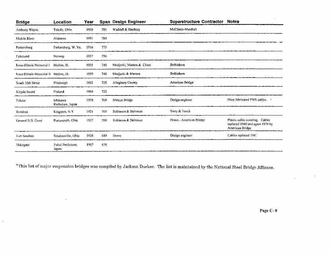
Major Suspension Bridges *
Bridge Location Year Span Design Engineer Superstructure Contractor Notes
Hirado Ohashi Hirado Island, Japan 1977 I526 Nagasaki Prefecture Mitsubishi -Nippon Steel - Sasebo
Page C- 4
Bridge Location
Vincent Thomas San Pedro, Calif.
Year Span Design Engineer Superstructure Contractor Notes
1963 I500 California Division of Highways - G. Kaiser - Yuba - Roebling B. Woodruff
Mid-Hudson Poughkeepsie, N.Y. 1930 1495 Modjeski & Moran American Bridge
Manhattan
Angus L. MacDonald
New York City
Halifax, Nova Scotia
1909 1470 L. L. Buck - L. S. MoisseifT Phoenix Bridge -Terry & Tenth Highway & railway
1955 1447 Dominion Bridge
Male Kap Shui Mun Hong Kong 1997 1447 Mott MacDonald
A. Murray Mackay Halifax, Nova Scotia
1970 1400 Pratlcy & Dorton Canadian IIridgc
Triborough
Alvsborgsbron
New York City
Gothenburg, Sweden
1936
1966
1380 0. H. Ammann - A. Dana - L. S. American Bridge Moisseiff
t 1370 Concrete towers
Hadong-Namhae Pusan, South Korea 1973 1325 Nippon Steel - IHI 11-11
Baclan Bordeaux 1967 1292 Concrete towers
Amu-Daria River Turkistan 1964 1280
Cologne- Rodenkuchcn Cologne 1954 1240 I I. I lombcrg; Rendcl Palmer & Tritton Strabag - ‘I’hysscn( 1954): Cleveland Widened by adding tower legs and (1992) cables 1992
St. Johns Portland, Ore. 1931 1207 Robinson & Steinman Wallace Bridge - Roebling - La Pointe
Wakato Narrows
Mount Hope
Kitakyushu City, Japan
Mount Hope Bay,
1962
1929
1204 Japan Highway Public Corporation Yokogawa Widened to 4 lanes, additional cables installed 1990
1200 Robinson & Steinman Bethlehem - Keystone
International Ogdensburg, N.Y. 1960 I150 Modjeski & Masters - P. L. Pratley American Bridge
I lcrcilio Luz Florianopolis Island, Brazil
1926 III4 Robinson & Steinman American Bridge
Page C- 5
Bridge Location Year Span Design Engineer Superstructure Contractor Notes
Bidwcll Bar Oroville, Calif. 1965 I 108 Calif. Dept. of Waler Resources Bethlehem Plastic cable covering
1057 John A Roebling (1866); Wm. John A. Roebling( 1866); Wm. Widened to 4 lanes, additional cables I lildenbrand (I 898) Hildenbrand( 1898) installed 1898 I
1050 I IN’I‘B Fought
1050 Frccnian Fox Dorman Long
IO34 M.A.N. Design engineer
1030 I lcmy G. Tyrrell Wm. Hildenbrand
Whcsling I849 IO10 Charles lillcl Design cnginccr First bridge span in the world IO exceed 1,000 R;destroyed by windi 854. Rcbult (by Ellet) I856
Bidwcll Bar Orovillc Gorge, Cal i f.
1854 1010 Moved to new location 1965
New Elizabeth Budapest 196s 984 UVilkrV - FOmtcrv Ganz-MAVACi - Massanyi - Fckcte - vovt
Konohana Osaka 1987 984 f lanshin Expressway Public Corp. Hitachi - Mitsubish Shop-fabricated PWS monocable
Elizabeth Budapest 1964 951 A. Czechelius Mavag-Ganz Metals
Page C- 6
Bridge Location Year Span Design Engineer Superstructure Contractor Notes
Tjeldsund Bjerkvik, Norway 1961 951
Gran’Mere Quebec City 1929 949 Robinson & Steinman Roebling
Cauca River Columbta I894 940
Peace River Alberta, Saskatchewan
1950 932
Cornwall-Massena International
Massena, N.Y 1958 900 Steinman
Terenez Aulne, France 1952 892
Brevik
Royal Gorge
I ligashi-Ohi
Kjerringstraumen
Telemark, Norway
Canon City, Colo.
Kumamoto Prefecture, Japan
Nordland, Norway
1962
1929
1976
1975
892 Concrete towers
880 G. E. Cole Midland Bridge
866 Kurimoto Shop fabricated PWS cables. I
853
Rognonas Viviers, France 1949 833
Kamryoshinagawa Kochi Prefecture, Jaoan
1972 832
Cuscatlan El Salvador 1943 820 American Bridge Design engineer
Dome Dome, Arrz. I929 800 Arizona I lighway Department Roebling
Waldo-Hancock Bucksport. Maine 1931
Thousand Islands Clayton. N.Y 1938
800 Robinson & Steinman American Bridge
800 Robinson & Steinman - Monsarrat & American Bridge Prallev
KOSUI Ohdan Kochi Prefecture, Janan
Rumania - Yugoslavta
1983 787 Shop fabricated PWS cables.
Iron Gate II 1994 187 Victor Popa Sorin Heinman - ENERGO - MONTAGE
Page C- 7
Bridge Location Year Span Design Engineer Superstructure Contractor Notes
700 Robinson & Steinman Dravo - Americnn Bridge Plastic cable covering. Cables replaced 1940 and agam 1979 by American Bridge
689 Dravv Design engineer Cables replaced I94 1
676
‘kThis list of maj or suspension bridges was compiled by Jackson Durkee. The list is maintained by the National Steel Bridge Alliance,
Page C- 8
J A C K S O N D U R K E E , C . E . , P . E .
CONSULTING STRUCTURAL ENGINEER217 PINE TOP TRAIL
BETHLEHEM , PENNSYLVANIA 180 17
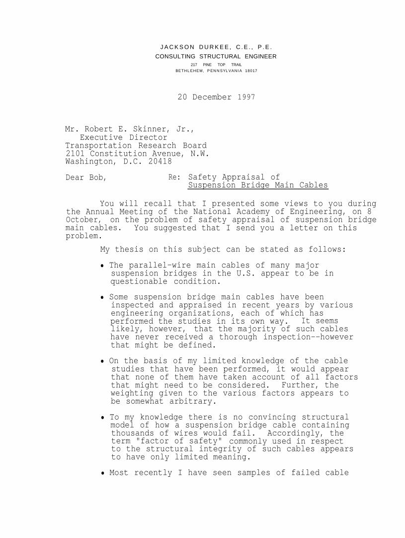
20 December 1997
Mr. Robert E. Skinner, Jr.,Executive Director
Transportation Research Board2101 Constitution Avenue, N.W.Washington, D.C. 20418
Dear Bob, Re: Safety Appraisal ofSuspension Bridge Main Cables
You will recall that I presented some views to you duringthe Annual Meeting of the National Academy of Engineering, on 8October, on the problem of safety appraisal of suspension bridgemain cables. You suggested that I send you a letter on thisproblem.
My thesis on this subject can be stated as follows:
l The parallel-wire main cables of many majorsuspension bridges in the U.S. appear to be inquestionable condition.
l Some suspension bridge main cables have beeninspected and appraised in recent years by variousengineering organizations, each of which hasperformed the studies in its own way. It seemslikely, however, that the majority of such cableshave never received a thorough inspection--howeverthat might be defined.
l On the basis of my limited knowledge of the cablestudies that have been performed, it would appearthat none of them have taken account of all factorsthat might need to be considered. Further, theweighting given to the various factors appears tobe somewhat arbitrary.
l To my knowledge there is no convincing structuralmodel of how a suspension bridge cable containingthousands of wires would fail.term "factor of safety"
Accordingly, thecommonly used in respect
to the structural integrity of such cables appearsto have only limited meaning.
l Most recently I have seen samples of failed cable
Mr. Robert E. Skinner Jr.
wires from a well-known major U.S. suspensionBridge, that exhibit what has been termed "squarebreaks." How widespread, and how serious, thisproblem might be on the cables of this bridge isnot known.
• I am informed that this problem of "square breaks"might exist in The cables of other major suspensionbridges, in addition to those of the bridge underreview. There is the prospect that this problemcould be widespread.
l There seems clearly to be no agreed-upon,recognized procedure to appraise and evaluate thecondition, strength and safety of suspension bridgemain cables. Accordingly, as individual bridgesare placed under review, each engineeringorganization called upon must perforce develop itsown procedures.
My conclusion from all of these considerations, asmentioned to you on 8 October, is that the U.S. needs a researchproject to identify and investigate the factors relevant to thestrength and adequacy of suspension bridge main cables, and todevelop these factors into a logical and suitable procedure toappraise cable safety aspects.
Many references could be cited to illustrate the need fora cable safety appraisal procedure, such as the following:
l IABSE workshop "Evaluation of Existing Steel andComposite Bridges," held in Lausanne, Switzerlandin March 1997. (See enclosed article from"Structural Engineering International,"Vol. 2 No.2, May 1997.) The aim of the workshop was toidentify promising scientific work and developevaluation methods what might be suitable for usein structural safety appraisal of these structures.The significant factor here is that even forordinary structures such as short- and medium-spansteel and composite bridges, there is no recognizedprocedure for structural safety evaluation.
l Paper "Safety Analysis of Suspension-Bridge Cables:Williamsburg Bridge" by Matteo, Decdatis &Billington, Journal of Structural Engineering,ASCE, Vol. 120 No. 11, November 1994. (See copyenclosed.) The objective of this paper was toestimate the safety factor of the corroded
J A C K S O N D U R K E E
CONSULTING STRUCTUAL ENGINEER
Mr. Robert E. Skinner, Jr.
Williamsburg main cables, defined as the ratio ofpredicted actual remaining strength to calculatedmaximum force. As I see it, this definition hasno real meaning in the absence of a definitivefailure model for a large parallel-wire suspensionbridge cable. Further, nothing is said in thepaper regarding such factors as the effect oftransverse pressure (in saddles and under cablebends) on wire tensile strength, the effect of wirekinks at the edges of tightened cable bands, andthe local cable bending effect caused by theconcentrated vertical loads applied at the cablebands by the suspenders. A review of this paperwill disclose a number of other questions: forexample, there is no estimate of the frequency atwhich wires may be breaking, and the effect of suchongoing breakage on future cable strength and"factor of safety."
l Paper "Cable Safety Factors for Four SuspensionBridges" by Haight, Billington & Khazem, Journalof Bridge Engineering, ASCE, Vol. 2 No. 4,November 1997. (See copy enclosed.) This paperreports on the evaluation of the cables of theWilliamsburg (1903), Bear Mountain (1924),Triborough (1936) and Golden Gate (1937) suspensionbridges. Table 1 of the paper lists 46 U.S.suspension bridges with main spans of 700 ft(213 m) or more, 27 of which (59%) are over 50 yearsof age. From a review of this paper, several keyquestions come forward. For example, in no casewould I Judge the determination of either thenumber or the effect of broken cable wires to bepersuasive. Nothing is said about the adverseconditions that usually exist within the cableanchorage chambers. Further, it may be noted thatin the case of each bridge (see Fig. 3) the"current ductile-brittle safety factor" issignificantly less than the "original actual safetyfactor"; the ratios range from about 83% for GoldenGate on down to about 56% for Triborough. Suchlosses are highly significant, and must be assumedto exist on most if not all of the older bridgeslisted in Table 1 and must be assumed to beprogressing.
The available evidence points clearly to the stark factthat the main cables of many major U.S. suspension bridges areindeed in questionable condition. It is likely that many such
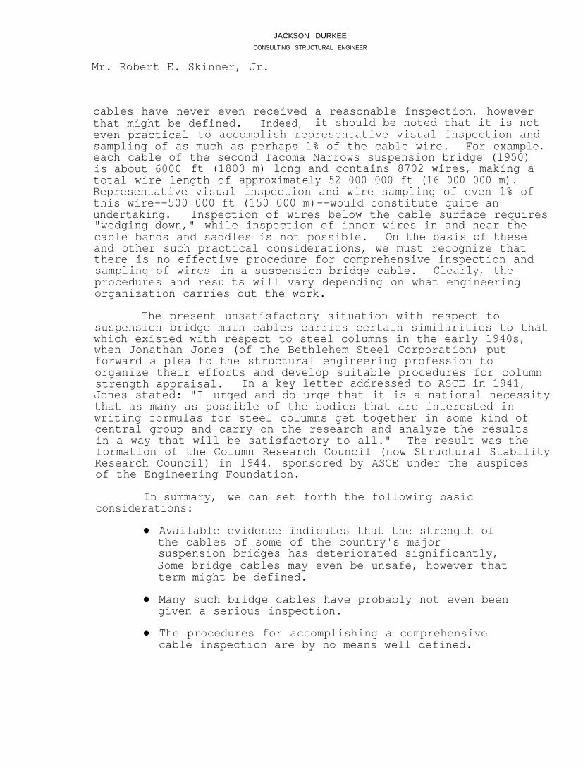
JACKSON DURKEECONSULTING STRUCTURAL ENGINEER
Mr. Robert E. Skinner, Jr.
cables have never even received a reasonable inspection, howeverthat might be defined. Indeed, it should be noted that it is noteven practical to accomplish representative visual inspection andsampling of as much as perhaps 1% of the cable wire. For example,each cable of the second Tacoma Narrows suspension bridge (1950)is about 6000 ft (1800 m) long and contains 8702 wires, making atotal wire length of approximately 52 000 000 ft (16 000 000 m).Representative visual inspection and wire sampling of even 1% ofthis wire--500 000 ft (150 000 m)--would constitute quite anundertaking. Inspection of wires below the cable surface requires"wedging down," while inspection of inner wires in and near thecable bands and saddles is not possible. On the basis of theseand other such practical considerations, we must recognize thatthere is no effective procedure for comprehensive inspection andsampling of wires in a suspension bridge cable. Clearly, theprocedures and results will vary depending on what engineeringorganization carries out the work.
The present unsatisfactory situation with respect tosuspension bridge main cables carries certain similarities to thatwhich existed with respect to steel columns in the early 1940s,when Jonathan Jones (of the Bethlehem Steel Corporation) putforward a plea to the structural engineering profession toorganize their efforts and develop suitable procedures for columnstrength appraisal. In a key letter addressed to ASCE in 1941,Jones stated: "I urged and do urge that it is a national necessitythat as many as possible of the bodies that are interested inwriting formulas for steel columns get together in some kind ofcentral group and carry on the research and analyze the resultsin a way that will be satisfactory to all." The result was theformation of the Column Research Council (now Structural StabilityResearch Council) in 1944, sponsored by ASCE under the auspicesof the Engineering Foundation.
In summary, we can set forth the following basicconsiderations:
l Available evidence indicates that the strength ofthe cables of some of the country's majorsuspension bridges has deteriorated significantly,Some bridge cables may even be unsafe, however thatterm might be defined.
l Many such bridge cables have probably not even beengiven a serious inspection.
l The procedures for accomplishing a comprehensivecable inspection are by no means well defined.
JACKSON DURKEECONSULTING STRUCTURAL ENGlNEER
Mr. Robert E. Skinner, Jr.
•
•
•
There is no logical and accepted method fortransforming cable inspection data into cablestrength data.
The concept "cable factor of safety" is vague,and calculated values for a given bridge cablehave no clear meaning.
The failure of the main cables of even a "minor"suspension bridge would constitute a catastrophe,and call into question the cables of most othersuspension bridges. Suspension bridge main cablesare non-redundant components, and when one cablefails the opposite cable will most likely alsofail, followed by collapse of the towers anddropping of the suspended deck structure.
In view of these considerations, I see a pressing need forlaunching a project to develop procedures for safety appraisal ofsuspension bridge main cables. It appears to me that you andthe Transportation Research Board are in the best position toevaluate the priority of such a project in respect to othernational engineering needs, and then to determine how theproject could be initiated and carried forward.
Yours sincerely,
JD:jsEnclosures
Copies: Dr. G. Wayne Clough, ChairmanCivil Engineering SectionNational Academy of EngineeringDr. Wm. A. Wulf, PresidentNational Academy of Engineering
E-1
APPENDIX E
BIBLIOGRAPHY
1. Betti, R., Yanev, B., “Conditions of Suspension Bridge Cables: The New York City Case Study”. This paper was presented at the 1999 Annual Meeting of the Transportation Research Board.
2. Csogi, “Manhattan Bridge, Rehabilitation of the Main Cable Eyebars, Cable “C” at
the Manhattan Anchorage.” 3. Durkee, J.L. & Thomaidas, S.S., “Erection Strength Adequacy of Long Truss
Cantilevers”, Journal of the Structural Division, ASCE, January 1977. 4. Fisher, J., Kaufmann & Pense, A., “Effect of Corrosion on Crack Development and
Fatigue Life”, Transportation Research Board Proceedings 1998 Annual Meeting, Paper #981038.
5. Haight, R.Q., Billington, D.P., & Khazem, D., “Cable Safety Factors for Four
Suspension Bridges”, ASCE Journal of Bridge Engineering, Vol. 2, No. 4, November, 1997, Paper #13321, pp157-167.
6. Hopwood, Theodore. “Ohio River Suspension Bridges: An Inspection Report”
Kentucky Transportation Research Program, Research Report UKTRP-81-6, June 1981.
7. Kendall, M.H., “Cable Restoration - Brooklyn and Williamsburg Bridges”.
Proceedings Suspension Bridge Operators Conference, April 17 & 18, 1991, Poughkeepsie, New York.
8. Kendall, M.H. & Sluszka, P. “In-depth Inspection of Suspension Bridge Main Cables
and Suspender Ropes”. Proceedings Second International Conference on Bridge Management, University of Surrey, Guildford, April, 1993.
13. Mondello, F.J., “Inspecting and Evaluating New York's East River Suspension Bridge Cables”. Proceedings International Bridge Conference, June 13-15, 1988, Pittsburgh, Pa.
14. Paulson, P., Cullington, D., “Evaluation of Continuous Acoustic Monitoring as a
Means of Detecting Failures in Post-tensioned and Suspension Bridges”, Proceedings XIII FIP Congress & Exhibition, May 23-29, 1998, Amsterdam.
15. Perry, R.J., “Estimating Strength of the Williamsburg Bridge Suspension Cables”, The
American Statistician, August 1998, Vol. 52, No. 3. 16. Robert, J.L., Laloux, R., “Non-destructive Control of Engineering Structure Cables”.
Bulletin Liaison Lab Ponts Chauss, 1974/03/04. 17. Sluszka, P. & Hayden, “Inspection, Evaluation and Rehabilitation of Suspension
Bridge Cables”. International Association for Bridge and Structural Engineering Symposium, Lisbon 1989, Volume 57/1.
18. Virlogeux, M., “Replacement of the Suspension of the Tancarville Bridge”. This
paper has been submitted to the Transportation Research Board for the 1999 Annual Meeting.
19. Yanev, B. “Infrastructure Management Systems Applied to Bridges”, Proceedings
International Symposium on Operation and Maintenance of Large Infrastructure Projects, Balkema, Rotterdam, 1998. ISBN 9054109637.
20. Yanev, B. “Keeping a Hold on History”, Bridge Design and Engineering, Third
Quarter, 1998.
21. Yanev, B. “The Management of Bridges in New York City”, Engineering Structures, Vol. 20, No. 11, 1998.
This is not a technical paper, but provides a description of this equipment to provide real-time monitoring of suspension bridge integrity.
23. “Seismic Performance of Long-Span Suspension Bridges in the United States”, by
Subcommittee on Seismic Performance of Bridges, IABSE Symposium, San Francisco, August 23-35, 1995.
24. “SoundPrint - Continuous Structural Monitoring”, PURE Technologies, Calgary,
Alberta, Canada. This is not a technical paper, but provides a description of this equipment to locate failures in high-tensile steel wire, strand or cable.