29
Olympus NDT PV100 Series Nicholas Bublitz Global Products Support Specialist
| Date post: | 16-Jul-2015 |
| Category: |
Technology |
| Upload: | olympus-ims |
| View: | 142 times |
| Download: | 0 times |

Olympus NDT PV100 Series
Nicholas BublitzGlobal Products Support Specialist

PV Series Description
� The PV Series is a “solution” package. Different configurations can meet customer’s applications.

PV (Pressure Vessel) Series Description
� The “PV” Series solutions
include:
– Acquisition unit
– Scanner
– Applicable Accessories
– Setup and Analysis Tools

Typical AUT Techniques

Applicable Customers and Codes
♦ PV100 is predominately geared towards the following two customers
– Manufacturing companies utilizing AWS, API and ASME codes for weld inspection (pressure vessels, piping etc.).*
– Service companies performing weld inspection to AWS and ASME and API requirements*
*and other codes outside North America

Wind Tower Manufacturers
♦ Typically inspected with manual shear wave to AWS D1.1, a typical tower weld is 14-40’ in circumference taking hours to manually inspect a single weld with no record of data
♦ Radiography is often used as well. Besides disruption of production or movement of parts to a safe area, radiography does not provide depth information for repairs

Service Providers
♦ Many manufacturing weld inspection services are outsourced to an outside source.
♦ Also, many welds in oil and gas, structural and other industries require regular inspection to ensure safety.
♦ AUT systems like the PV100 series offer many unique advantages over more conventional ultrasonics and radiography.
PV100 Technique

PV100 Description
♦ PV100 is a generic description for a weld inspection package utilizing more conventional ultrasonic techniques (Shear wave, TOFD, Creeping Wave)
♦ Package tools are determined predominately by wall thickness and code conformance
♦ Although we use PV100 generically, there are actually several packages available based upon customer requirements (PV100-101-102)

PV100 Technique♦ Technique varies on applicable code
requirements and wall thickness– PV100 Wall thickness ~10-30 mm
– PV101 Wall thickness ~30-160mm
– PV102 Wall thickness ~150-300mm
♦ Application Example: Typical wind towers have a thickness range of 12 – 46mm. They might utilize both the PV100 and 101 techniques.

PV100 Ultrasonic Techniques♦ PV100 incorporates TOFD for the
volume and shear wave Pulse Echo for the weld cap and root (from each side)
♦ PV101 incorporates 2 channels of TOFD (volume and root) and Creeping wave for the weld cap
♦ Other configurations of these and other conventional ultrasonic methods (refracted longitudinal wave etc.) may still be referred to as PV100 generically

TOFD
♦ Uses send and receive probes
♦ The incoming wave vibrates the defect and emits energy in all directions
♦ The receiver gets one or more signals from the defect

Wave Propagation
FLAW
Diffractedwaves
Diffractedwaves
Incidentwave
Reflectedwave
All directions - Low energy - Independent of incidence angle

TOFD Limitations� Blind areas :
– Near surface Due to the width of the lateral wave as well as timing inaccuracies Can be reduced by reducing PCS, using higher frequency probes, incorporating highly dampened broadband transducers, as well as software tools (lateral wave removal). These minimize, but do not eliminate the near surface dead zone.
– Back wall Large signal from reflected energy at the back wall creates a dead zone as well

Recommended Solution
♦ TOFD is a very good tool for weld inspection.
♦ However, it does have some limitations, Pulse Echo can cover these limitations.
♦ SOLUTION: Incorporate both TOFD and PE simultaneously
♦ Pulse Echo channels can be targeted on the cap and root, TOFD’s weak spot for a full volumetric inspection.

Recommended Solution: PV-100

TOFD Data
♦ Side View
♦ Grey scale palette
♦ Sized with cursors
TopVolume
Back Wall

PV100 Principles
� A combination of both TOFD & Pulse-echo channels, proves to cover the weld zone generously when setup correctly

PV101 Technique
♦ PV101 adds multi-zone TOFD with the addition of the creeping wave technique
♦ This is implemented to address possible poor detection and sizing with pulse echo at the top on thicker material
♦ Creeping waves are designed to cover just a few millimeters below the surface for defects.

Radiography Replacement
♦ The PV series is suitable for codes where radiography replacement by ultrasonics is allowed
♦ Some of the benefits include no radiation hazards to contend with, no need to stop other productions, and height sizing

PV100 Main Solution Components
♦ NDT Setup Builder
♦ Scan plan Design Software
♦ Setup imported directly into OmniScan

PV100 Main Solution Components
♦ OmniScan MX2 8 channel acquisition unit
♦ TomoView or OmniPC Analysis software

PV100 Main Solution Components
♦ Mechanical Scanner
– HSMT-FLEX or X03 for semi-automated requirements
– WeldROVER for automated requirements

PV100 Main Solution Components
♦ Couplant Delivery
– Water Sprayer – manually operated
– CFU – automatic water flow system
PV100 Main Solution Components
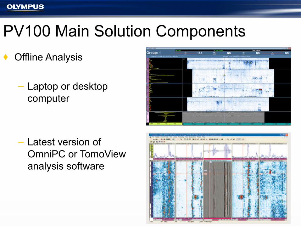
♦ Offline Analysis
– Laptop or desktop computer
– Latest version of OmniPC or TomoView analysis software

PV100 Main Solution Components
♦ Accessories (variable)
– Probes/wedges– Spare parts– Umbilicals/cabling– Preamplifiers– Calibration and
performance blocks

Reporting
� The Olympus NDT OmniPC and TV software offer the ability to thoroughly analyze acquisition data.
� In addition they also provide a full suite of reporting tools

Performance/Calibration Blocks♦ Used to calibrate system and define performance
♦ Used to validate technique over required range
♦ Used to test and validate operators
♦ Typically contains notches and SDH in pattern displaying coverage and effective detection and sizing capabilities

For additional information or to download a product brochure please visit:
http://www.olympus-ims.com/en/pv-100/
Thank you!


