NEAR EAST UNIVERSITY Faculty of Engineering Department of Electrical and Electronic Engineering CELLULAR COMMUNICATION SYSTEMS Graduation Project EE-400 Submitted By: Amer Seder (20011812) Supervisor: Assoc. Prof. DR. Sameer lkhdair Nicosia-2006
Transcript
NEAR EAST UNIVERSITY
Faculty of Engineering
Department of Electrical and Electronic Engineering
CELLULAR COMMUNICATION SYSTEMS
Graduation Project EE-400
Submitted By: Amer Seder (20011812)
Supervisor: Assoc. Prof. DR. Sameer lkhdair
Nicosia-2006
AKNOWLEDGMENTS
At the beginning I would like to thank ALAH and my family, specially my parents
there continuous support and endless love, brought me to this position. I would like to
dedicate this work as a humble thanking for themJ wish them a place in the heaven
after a long healthy and happy life.
Special thanks to my supervisor Assoc. Prof Dr Sameer Ikhdair for being my
advisor in this work. Under his supervision I was able to pass through many difficult
problems in my project, I learned a lot from him about the communication and the
telecommunications, he always answered my questions generously, and his answers
were more than enough for me. I really appreciate his efforts in supporting me
scientifically and immaterially.
Thanks to faculty of engineering specially and to Near East University generally for
providing such an interesting educational environment.
Finally, I also want to thank my life friends: Omar Yasin, Hamzeh shatnawi, Ahmad
Abu Shehab, Al Najjar, Adnan, Thaer and Haitham Abu Awwad, Being with them made
4 years of my life full of exciting, wonderful and fascinating moments, which I will never
forgot.
I
ABSTACT
Recently, the demand for wireless communication has grown tremendously, and
consequently cell sizes have decreased to meet this demand. Small cells are now used to
increase the capacity of the system by reusing the resources more intensively in high
traffic demand areas (Guerrero and Aghvami, 1999). Indeed, as small cells are needed
to achieve higher capacities, increasing handoff rates are expected, leading to the
undesirable consequence of an increase in the switching load of the network
This project is mainly explain the cellular communication system so that it gives a
'general information about the basic cellular system and also the operation of the cellular
system, the required bandwidth and also the frequencies, so that it will give a full view
for the reader about the cellular communication systems.
Results have formed the initial core base of the users' requirements. In addition, a
technical analysis of the state-of-the-art of the mobile technologies has been conducted
to identify key issues for the migration of existing services toward the UMTS, taking
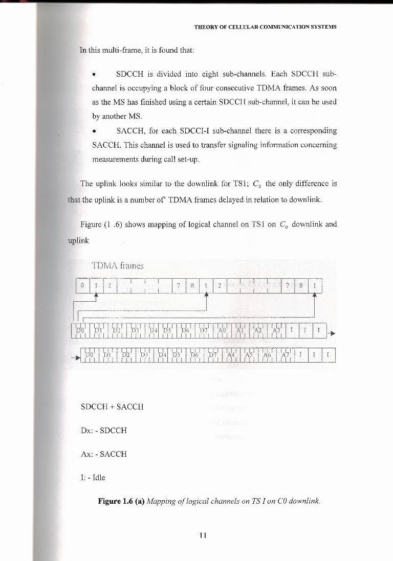
Figure 1.6 (a) Mapping of logical channels on TS I on CO downlink.
11
THEORY OF CELLULAR COMMUNICATION SYSTEMS
SDCCH + SACCH
Dx: - SDCCH
Ax: - SACCH
I: - Idle
Figure 1.6 (b) Mapping of logical channels on TS I on CO Uplink
• The Traffic Channels
On TS2-TS7 on the CO and on TSO-TS7 on all the other carriers, the
information is grouped into 26 TDMA multi-frames. In these multi-frames it is
that;
• TCH, containing data or speech.
• SACCH, carrying the control signaling necessary during traffic, for
instance measurement data, power order, or timing advance order.
• Idle frames, this is not a logical channel, rather it is used to indicate
that the transmitter is off during this particular rmN4p frame. Figure (1 . 7)
shows 26 TDMA-multi-frame.
12
THEORY OF CELLULAR COMMUNICATION SYSTEMS
1.8 Handoff
Handoff is the switching of an on-going call to a different cell, which happens
when a user moves from one cell coverage to another. There are three phases of a
handoff procedure as shown in Figure (1.8).
..• !il·-l.ı»ıt•t ı,.ı;Hxh,:-rt~0"4:nM4ı,tlOuu:
'H)i'il;,'\. fUıt'\t1".•x;,ı i,:cı:, c,t,,ı l 3i mı,
- -
J'.fjjU'i/ttıJ;
~,tıı:}_l>tn.£r·
na Oı;ı,,.ıc:.!J.h:1 hiu
U'<!,ımıı!l:w:,nı:Dw:ttion a:;n:ııı ncu
''(;ıt
t>ıt1sa~hnt
fü;:ııı-$1,01~1
b
Figure 1.7 26-TDMA multi-frames
Handoff Procedure ·
Measurement oecısıon Execution
Figure 1.8 Phases of a handojfprocedure
These phases are:-
• Measurements: The mobile terminals as well as the access point
(Base Transceiver Station) do several measurements continuously. For e.g.
13
THEORY OF CELLULAR COMMUNICATION SYSTEMS
the signal strength is one parameter which might be measured by both the
terminal and the access point (Graziosi et al. 1999). In GSM, the mobile
station transmits report on up to 6 neighboring cells in addition to the
measurements relative to the serving cell, this reporting is carried by
messages on the small signaling channel associated with each traffic
channel and called the SACCH.
• Decision: based on the measurements taken, a decision is made as
to whether a handoff is required. For e.g. a decision to perform a handoff
might be taken if the signal strength goes below a specified threshold. In
GSM, the decision is taken by the Base Station Controller (BSC).
• Execution: the actual handoff of the terminal from one cell to
another is performed in this phase. There are two modes of handoff:
Synchronous and asynchronous. In synchronous handoff, the old and new cells
are synchronized so that their TDMA timeslots start at exactly the same time. In
asynchronous handoff, the old and new cells are unsynchronized, so the MS
cannot independently correct the timing advance in this way. There are essentially
two sub-phases in the execution of the handoff:
• New Link establishment.
• Release of old link.
There are three types of handoff in GSM based on the position of the
switching point at handoff, all of which must be treated somewhat differently.
First, there is handoff from one radio channel to another of the same BSC, which
is known as intra-HSC handoff. Second, there is handoff between channels of
different BSCs under the control of the same Mobile-Service Switching Center
(MSC), which is known as inter-BSC handoff. Third, there is handoff between
channels under the control of different MSCs in the same Public Land Mobile
Network (PLMN), which is known as inter-MSC handoff. Figure (1 .9) shows
these three types of handoff. The detailed protocols for these three types will be
provided in the following section.
14
THEORY OF CELLULAR COMMUNICATION SYSTEMS
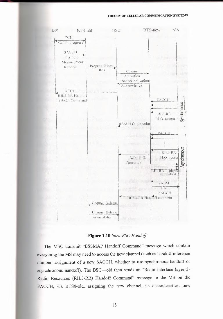
1 Intra-DSC Handoff
Figure (1.10) shows a handoff process between channels of the same BSC.
e MS is shown at both ends, indicating its connection to the old and new BTSs.
"ith a call in progress, the BSC may determine if a change of channel is i
essary. The BSC is aware of all the relevant information since it already
manages the current context of the connection. The BSC allocate TCH in a new·,cell, choose handoff reference number which it uses to determine whether the
correct mobile gains access to the air-interface channel which it allocates, then the
BSC order BTS-new to activate it with a "Radio Subsystem Management (RSM)
Channel activation" message. BTS-new responds with an "RSM Channel
Activation Acknowledge" message to the BSC. The BSC then sends a "Radio
interface layer 3-Radio Resources (RIL 3-RR) Handoff Command" message to the
Y!S on the FACCH, via BTS-old, assigning the new channel, its characteristics,
new SACCH, and whether to use synchronous or asynchronous handoff. Upon
receiving this message, the MS suspends all transmission of signaling messages
except those RR messages concerning the Handoff until resuming is indicated by
set asynchronous balances mode (SABM) message, initiates the release of the old
channel and connection to the new one.
15
THEORY OF CELLULAR COMMUNICATION SYSTEMS
Figure 1.9 Mobile handoff
Two procedures are possible depending on whether the on and new cells are
synchronized or not. In the synchronous mode, after switching to the new channel,
the MS sends to the new BTS, in successive assigned multi-frame slots on the
FACCH, four "RIL3-RR Handoff Access" messages. It then activates the new
channel in both directions. When it has received sufficient "Handoff Access"
messages, the new BTS may also send an "RSM Handoff Detection" message to
the BSC.
In asynchronous mode, the MS starts sending a continuous stream of "RIL3-
RR Handoff Access" messages to the new BTS until it receives in response an
"RIL3-RR Physical information" message giving the timing advance to apply. For
efficiency reasons, the "RIL3-RR physical information" message may be sent
several times in a row, until the reception of "set asynchronous balances mode
(SABM)" frame from the MS makes it clear to BTS-new that it has received the
message, this message answered by an "unnumbered ACK (UA)" flame.
16
THEORY OF CELLULAR COMM1JNICATION SYSTEMS
After the lower layer connections are successfully establishes, the MS sends
an "RIL3-RR Handoff Complete" message to the BSC over the new FACCH. The
BSC directs BTS-old to release the old channel by sending an "RSM RF Channel
Release" message with Acknowledgement from BTS-old (MOULY and
PAUTET, 1992).
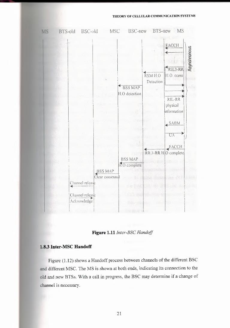
1.8.2 Inter-DSC Handoff
Figure ( 1.11) shows a handoff process between channels of the same MSC but
different BSC. The MS is shown at both ends, indicating its connection to the old
and new BTSs. With a call in progress, the BSC may determine if a change of
hannel is necessary. The BSC sends a "base station system management part
(BSSMAP) Handoff required" message to MSC, containing the identities of the
target cell and of the origin cell. When receiving the indication that a handoff is
required, the MSC transmits a "BSSMAP Handoff request" message to BSC-new,
including the information on the cells (both the origin and target cells), the class
mark and the cipher mode. The BSC-new allocates TCH in new cell, choose
handoff reference number then order BTS-new to activate it by a "Radio
This is a polynomial representation of the code word
(xıı-2, xıı_ı ,···, xıı-3)
2.3.1 Encoder for Cyclic Codes
Earlier we showed that the encoding procedure for an (n, k) cyclic code. These three
steps can be implemented by means of the encoder shown in Figure 2.2 Consisting of a
linear feedback shift register with (n-k) stages.
31
CHANNEL CODING
••• Flip-flop Modulo-2
ıdder Code
Message bits • • crEncoder for an (n,k) cyclic code.
Figure 2.2 Encoderfor Cyclic Codes
The operation of the encoder shown proceeds as follows:
1- The gate is switched on. Hence, the k message bits are shifted into the channel.
As soon as the k message bits have entered the shift register, the resulting (n-k)
bits in the register form the parity bits (recall that the parity bits are the same as
the coefficients of the reminder b (D).2- The gate is switched off, thereby breaking the feedback connections.
3- The contents of the shift register are shifted out into the channel.
Calculation of the Syndrome: Suppose the code word (x0, Xı, ... , xn_ı) is transmitted
over a noisy channel resulting in the received word (y0, Yı , ... , y n-ı).
Let the received word be represented by a polynomial of degree n- 1 or less, as
shown by:
y(D) =Yo+ YıD + ··· + Yıı-ıD"-ı (2.3.5)
Let a (D) denote the quotient and s (D) denote the remainder, which are the results
of dividing y (D) by the generator polynomial g (D).Therefore
y(D) = a(D )g(D)+ s(D) (2.3.6)
32
CHANNEL CODING
The remainders (D) is a polynomial of degree n-k or less. It is called the syndrome
lynomial in that is coefficients make up the (n-k) -by- 1 syndrome s. When the
syndrome polynomial s (D) is nonzero, the presence of transmission errors in the
received word is detected
Flip-flop Moduio,2adder
Syndrome calculator.
Figure 2.3 Syndrome calculator
The figure 2.3 shows a syndrome calculator that is identical to the encoder except
for the fact that the received bits are fed into the (n-k) stages of the feedback shift
register from the left.
2.4 Convolutional Codes
There are applications where the message bits come in serially. In such situations,
the use of convolution coding may be the preferred method. A convolution encoder
operates on the incoming message sequence continuously m a serial manner.
The encoder of a binary convolution code with rate 1/n, measured in bits per
symbol, may b viewed as a finite-state machine that consists of an M-stage shift register
with prescribed connections to n modulo-2- adders, and a multiplexer that serialized the
outputs of the adders. An L-bit message sequence produces a coded output sequence of
length n (L+M) bits. The code rate is therefore given by
33
CHANNEL CODING
r= Ln(L + M) Bits I symbol(2.3.7)
Typically, we have L> M. Hence the code rate simplifies as
r = _!_ Bit/symboln
(2.3.8)
Flip flop
Figure 2.4 convolution encoder
The constraint length of a convolution code, expressed in terms of message is
defined as the number of shifts over which a single .message bit can influence the
encoder output K=M +l, the constraint length of the encoder is Figure 2.4 shows a
convolution encoder with n = 2 and k = 3 . Hence the code rate of encoder= 1/2. The
.,~
encoder operates on the incoming message sequence, one bit at a time.
2.5 Code Tree, Trellis, and State Diagram
Traditionally, the structural properties of a convolution encoder are portrayed in
graphical form by using any one of three equivalent diagrams:
Code, tree, trellis, and state diagram.
We will use the convolution encoder of Figure 2.4
34
CHANNEL CODING
-o
8
Figure 2.5 Code tree for the convolution encoder of Figure 2. 4
We begin the discussion with the code tree of Figure 2.5 Each branch of the tree
represents an input symbol, with the corresponding pair of output binary symbols
indicated on the branch. The convention used at distinguish the input binary symbols O
and 1 is as follows. An input O specifies the upper branch of a bifurcation, while input 1.specifies the Lowe branch. A specific path in the tree is traced from left to right in
accordance with input (message) sequence. The corresponding coded symbols on the
branches of that path constitute the sequence supplied by the encoder to the discrete
channel input.
From diagram of Figure 2.5 we observe that the tree becomes repetitive after the
first branches.
We may collapse the code tree of Figure 2.5 into the new form shown in Figure 2.6,
called a trellis. It is so called since a trellis is a tree-like structure with remerging
branches. The convention used in Figure 2.5 to distinguish between input symbols O and
1 as follows. A code branch produced b an input O drawn as solid line, while a code
branch produced by an input 1 is drawn as a dashed line. As before each input
(message) sequence corresponds to a specific path through the trellis.
35
CHANNEL CODING
d
Depth i•O 1 l L+1 l+2
Figure 2.6 Trellisfor the convolution encoder
A trellis is more instructive than a tree in that it brings out explicitly the fact that the
associated convolution encoder is a finite-state machine. We define the state of a
convolution encoder of rate ljn as the most recent (K-1) message bits moved into the
encoder's shift register.
In. case of the simple convolution encoder of Figure 2.4, we have (K-1) =2. Hence,
the state of this encoder, can assume any one of four possible values, as described in
Table 2. 1 the trellis contains (L + K) levels, where L is the length of the incoming
message sequence, and K is the constraint length of the code.
Table 2.1 state tablefor the convolution Encoder
36
CHANNEL CODING
,o ,--~I \t I' ,', ,,
''d
.,,,,,//
,/01 _/
,///// '10
,, _,.,,-----~----- ', 00',
'~ ,,,11,
' ', ',,
00
Figure 2. 7 state diagram of tll e convolution encoder
We follow a solid branch if the input is a" o" , and a dashed branch if it is a" l .
Thus, the input relation of a convolution encoder is completely described by its state
diagram.
2.6 The Communications Channel
All communications systems and methods require a channel. This is because
sending a message from one point to another involves the transmission of energy. All
communications depend on the transfer of energy. The energy may be in various forms,
such as light, electromagnetic waves, heat, sound, or mechanical motion. The channel is
the path, or conduit, for hits energy.
The term "channel" as used in the communications industry includes both the path
energy and the path for the energy, but it may also encompass other aspects of the
overall link.
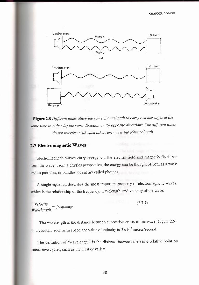
A channel may carry signal, multiple signals in the same direction, or multiple
signals in opposite directions.
37
CHANNEL CODING
Loudspeaker necf!iveı'-
(a)
Loudspeaker Receiver
·]Loudspeaker
Receiver •·
Figure 2.8 Different tones allow the same channelpath to carry two messages at the
same time in either (a) the same direction or (b) opposite directions. The different tones
do not interfere with each other, even over the identicalpath.
2. 7 Electromagnetic Waves
Electromagnetic waves carry energy via the electric field and magnetic field that
form the wave. From a physics perspective, the energy can be thought of both as a wave
and as particles, or bundles, of energy called photons.
A single equation describes the most important property of electromagnetic waves,
which is the relationship of the frequency, wavelength, and velocity of the wave.
Velocity = frequencyWavelength
(2.7.1)
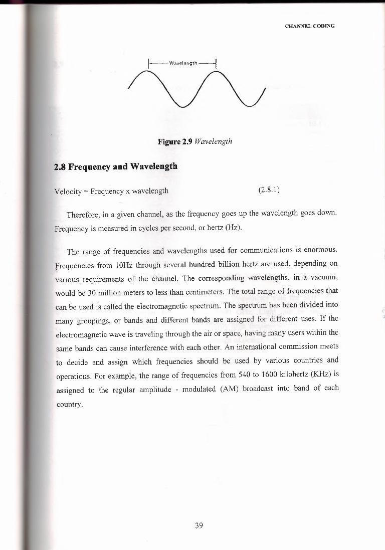
The wavelength is the distance between successive crests of the wave (Figure 2.9).
In a vacuum, such as in space, the value of velocity is 3 x 10⁸ meters/second.
The definition of "wavelength" is the distance between the same relative point on
successive cycles, such as the crest or valley.
38
CHANNEL CODING
1---Wavel!!rıgth ----1
Figure 2.9 Wavelength
2.8 Frequency and Wavelength
Velocity = Frequency x wavelength (2.8.1)
Therefore, in a given channel, as the frequency goes up the wavelength goes down.
Frequency is measured in cycles per second, or hertz (Hz).
The range of frequencies and wavelengths used for communications is enormous.
frequencies from 1 OHz through several hundred billion hertz are used, depending on
various requirements of the channel. The corresponding wavelengths, in a vacuum,
would be 30 million meters to less than centimeters. The total range of frequencies that
can be used is called the electromagnetic spectrum. The spectrum has been divided into
many groupings, or bands and different bands are assigned for different uses. If the
electromagnetic wave is traveling through the air or space, having many users within the
same bands can cause interference with each other. An international commission meets
to decide and assign which frequencies should be used by various countries and
operations. For example, the range of frequencies from 540 to 1600 kilohertz (KHz) is
assigned to the regular amplitude - modulated (AM) broadcast into band of each
country.
:;..
39
CHANNEL CODING
2.9 The Electromagnetic Spectrum
The electromagnetic spectrum has been divided into general bands, for convenience.
Very low frequency
Low frequency (LF)
Medium frequency (MF)
High frequency (HF) also called
"short wave"
Very high frequency (VHF)
Ultra high frequency (UHF) also
called "microwaves"
Super high frequency (SHF)
Table 2.2 the Electromagnetic Spectrum
The spectrum of visible light is at even higher frequencies than the SHF band.
Visible light has frequencies from 4300 to 7500 GHz. Light can be used for
communications , but because of the extraordinarily high frequencies , systems using
light must employ a completely different set of design of design schemes, even through
light is an electromagnetic wave.
N:ı:l'.)M
>uC N QI -,-::, -·er <..?::: o
LL. M
-"'ooM
N
~ooM
"'::ı::~oM
-"oCCc-.
1 LL l LL 11.L.LL. LL. LL LL. i~ _; _;:ı: :ı: i :ı: ~ >W V) ::ı I > i ! I
Figure 2.10 The major divisions of the electromagnetic spectrum (not shown to scale).
40
CHANNEL CODING
All the frequencies in the electromagnetic spectrum follow the same basic laws ofphysics. However, because of additional practical and real- world -word considerations,
such as water vapor in the air, the energy of waves, their ability to penetrate solidobjects, and the way they bounce and reflect the performance of communication
channel is greatly affected by the frequency which is used.
Atmospheric Layer
R~flectedwave
Earth
Figure 2.11 Transmitted signals can travel by direct line of sight or by reflection fromlayers of the atmosphere.
Noise is an undesired electrical signal that is superimposed on the desired signal.
The atmosphere of the earth and the vacuum of space may other sources of
electromagnetic signals. The ones deliberately generated by the transmitter for the
channel.
2.10 Bandwidth
Bandwidth is an extremely important concept in data communications. The
communications channel must have sufficient bandwidth to handle the amount of data
information that must be passed over it. If the bandwidth of the channel is too low, the
rate of data transfer may be less than required. If the channel is to handle more than one
signal, then the bandwidth of the channel must be equal to the sum of the bandwidths of
41
CHANNEL CODING
each signal. Bandwidth is a simple case of' you can't get something for nothing". The
price paid for transmitting data at the desired rate is the bandwidth needed.
Some typical examples of bandwidth will illustrate the relationship between
bandwidth and information rate. A voice signal, transmitted over the telephone, uses a
bandwidth of 3 KHz. A standard TV channel uses 6-MHz bandwidth, by contrast, of'
which 4.3 MHz is for the video information.
2.11 Bandwidth and Channel Capacity
A wider bandwidth is needed to carry information at a higher rate. What is the
specific relationship between the bandwidth needed and the data rate that can be
achieved (called the channel capacity) with that bandwidth? In 1984, Claude Shannon
showed by mathematical analysis that there was a specific MHz, simple formula that
related bandwidth and capacity:
Capacity= bandwidth X log 2 (1 + sig~alpower)noısepower
(2.11.1)
Where the capacity is measured in bits/second (bits/s), bandwidth in hertz and signal
and noise powers must be in the same units.
Note: log2 is log to the base 2, and for any number X
log, (x) = logıo(x) _ log10 (x)logıo(2) - 0.3
(2.11.2)
42
SPREAD SPECTRUM TECHNIQUES
3. SPREAD SPECTRUM TECHNIQUES
3.1 General Concepts
The discussions of communication systems in previous chapter have been concerned
with the efficiency with these systems utilize signal energy and bandwidth.
These are situations, however, in which it is necessary for the system to resist
external interference, to operate with a low-energy or to make it difficult for
unauthorized receivers to observe the message. In such a situation, it may be appropriate
to sacrifice the efficiency aspects of the system in order to enhance these other features.
Spread- spectrum techniques offer one way to accomplish this objective.
The use of spread-spectrum techniques originated in answer to the unique needs of
military communications, and it is reasonable to assume that these techniques will soon
penetrate the civilian sector. Therefore, a discussion of modem communications would
not be complete without a look at the fundamentals and the applications of spread
spectrum.
For a communication system to be considered a spread-spectrum system, it is
necessary that the transmitted signal satisfy two criteria. First, the bandwidth of the
transmitted signal must be much greater than the message bandwidth.
This by itself, however, is not sufficient because there are many modulation
methods that achieve it. For example, frequency modulation, pulse code modulation,
and delta modulation may have bandwidths that are much greater than the message
bandwidth. Hence the second criterion is that the transmitted bandwidth must be
determined by some function that is independent of the message and is known to the
receıver.
Since the spread-spectrum system is not useful in combating white noise, it must
have other applications that make it worth considering. These applications include:
1- Antijam capability - particularly for narrow-band jamming.
2- Interference rejection.
43
SPREAD SPECTRUM TECHNIQUES
3- Multiple-access capability.
4- Multipath protection.
5- Covert operation or low probability of intercept (LPI).
6- Secure communications.
7- Improved spectral efficiency - in special circumstances.
8- Ranging.
There are many different types of spread-spectrum systems and one way of
classifying them is by concept. On this basis spread-spectrum systems may be
considered to be either averaging systems or avoidance systems. An averaging system is
one in which the reduction of interference take place because the interference can be
averaged over a large time interval. An avoidance system, on the other hand, is one in
which the reduction of interference occurs because the signal is made to avoid the
interference a large fraction of the time.
A second method of classifying spread-spectrum systems is by modulation. The
most common modulation techniques employed are the following.
1- Direct sequence (pseudonyms)
2- Frequency hopping
3- Time hopping
4- Chirp
5- Hybrid methods
The relation between these two methods of classification may be made clearer by
noting that a direct -sequence system is an averaging system, whereas frequency
hopping, time hopping and chirp systems are avoidance systems. On the other hand, a
hybrid modulation method may be either averaging or avoidance, or both.
44
SPREAD SPECTRUM TECHNIQUES
3.2 Direct Sequence (DS) or PseudoNoise (PN)
The terms direct sequence and pseudnoise are used interchangeably here and no
distinction is made between them. A typical direct-sequence transmitter is illustrated m
Figure 3 .1 Note that it contains a PN code generator that generates the pseudonoise
sequence. The binary output of this code generator is added, modulo 2, to the binary
message, and the sum is then used to modulate a carrier. The modulation in this case is
diphase or phase reversal modulation so that the output is simply a phase shift keyed
signal. The PN code is generated in a maximal length shift register such as shown in
Figure 3.2.
Pseudnoise code generators are periodic in that sequence that is produced repeats
itself after some period of time. Such a periodic sequence is portrayed in Figure 3.3.
The smallest time increment in the sequence is of duration t 1 , and is known as a time
chip. The total period consists of N time chips.
When the code is generated by maximal linear PN code generator, the value of N is
2" -1, where n is the number of stages in the code generator. An important reason for
using shift register codes is that they have very desirable autocorrelation properties.
The autocorrelation function of a typical PN sequence is shown in Figure 3.4. Note
that on a normalized basis, it has a maximum value of one that repeats itself every
period, but in between these peaks, the level is at a constant value of-(1/N). If N is a
very large number, the autocorrelation function will be very small in this region.
Another reason for using shift register codes is that the period of the PN sequence
can easily be made very
45
SPREAD SPECTRUM TECHNIQUES
Binary I Binary adder I I Balanced I Transmitted
Imodulator
message I signal
tCarrier
PN code Lfo
generator Clock
Figure 3.1 Direct-sequence transmitters
Mod 2N ~ 2" - 1
2 n - 2 n - 1 n
CIOck
,.I
Figure 3.2 maximal linear PN code generators
---------Onechip
11 2r1 ar, Nt,
-1______. _
N = 2" - 1
ı-----------Orıe period--------~
Figure 3.3 Periodic binary PN sequence
The modulation of the PN sequence on the spread-spectrum carrier can be either
biphase or quardriphase. It is of interest to consider both of these methods.
46
-SPREAD SPECTRUM TECHNIQUES
R(~)
1
-1/N
o-ı, I ı,
Figure 3.4 Autocorrelation function ofPN sequence
3.3 Biphase modulation
A phase-modulation carrier can be expressed in general as
s(t) = Asin[w0t + ¢(t)] (3.3.1)
Where A is the constant carrier amplitude, and ¢(t) will be either zero or ff .The
values of ¢(t) for various combinations of the binary message m(t), and the PN
sequence, b(t), are shown in Table 3.1.
m(t)
1 -1
b(t) 1 oo-1
Table 3.1 Truth tablefor ¢(t)
A block diagram of a system accomplishing biphase modulation is shown in Figure
3.5. This system employs a balanced modulator that ideally produces the desired phase
shift keying without any residual carrier at the output. It is necessary that the message
bit <1j.uration tın be an integral multiple of the chip duration ı, as shown in Figure 3 .6.'"--
47
m(t) Mod2adder
Balancedmodulator
s(t)
SPREAD SPECTRUM TECHNIQUES
b(t) Carrier
Figure 3.5 Block diagram for bi phase modulation
I .. r-.~.. •· ,-1
PN sequence
o_,
Figure 3.6 Relation between the code sequence & the binary message
Mod 2 I · tBalanced ]addermodulator
ı: b,(t) L !m(I) I Alternate PN code
r Linear I s(I)
chips generator \ adder
Mod 2 Balancedadder modulator
Figure 3. 7 Block diagram for quadriphase modulation.
3.4 Quadriphase Modulation
A block diagram of a system producing quadriphase modulation is shown in Figure
3. 7. In this case two balanced modulators are used and the carriers to these two
m\dulators are 90 degrees apart in phase. There are also two modulo-2 adders that add
the message binary sequence to the PN code sequence, using alternate chips from the
code sequence to do so. This means that each chip of the PN code is stretched to
48
-SPREAD SPECTRUM TECHNIQUES
duration of 2t1 before being added to the binary message. The quadriphase signal can
again be represented as
s(t) = Asin[w0t + ¢(t)] (3 .4.1)
In which A is the carrier amplitude and ¢(t) is the phase modulation. The relation
of ıp(t) to the state of the message and the states of the PN code sequence is shown in
Table 3.2.
m(t)
\m(t)
bı (t) b~ (t.) 1 -1
1 1 'f(/4 51f/4
1 -1 7ı./4 3n- /A.
-1 1 3ır/4 7ır/4
-1 -1 5,r/4 rr./4
Table 3.2 Truth table of ¢(t)
3.5 PN Signal Characteristics
If PN sequence is considered to be purely random, rather than periodic, it is straight
forward to show that is spectral density has the form
(3.5.1)
In which the expression has been normalized to represent a signal having unit
average power. This spectral density is displayed for positive frequencies in Figure 3.8.
It is customary to define the bandwidth of a PN signal as the frequency increment'\ '~ between the two zeros of the spectral density that are closest to the center frequency, It
is clear from Figure 3.8 that this signal bandwidth is 2/t1 •
49
SPREAD SPECTRUM TECHNIQUES
Since the message is also binary, it will have a similar spectral density but centered
on zero. Thus the message spectral density is:
S (!) [sin dt ]2nı = fm ı;ı ııı
nft ; (3.5.2)
The bandwidth of the message Bııı is simply 1/tm because it is customary to use'
only the positive frequency portion of the spectrum in defining bandwidth.
An important parameter that is sometimes useful in specifying the performance of a
spread-spectrum signal in the presence is known as processing which is gain, PG, is
frequently defined as the ratio of the signal bandwidth to the message bandwidth. Thus:
Some authors define the processing gain as the ratio of the chip rate to the message
bit rate.
3.6 Frequency Hopping
In a frequency-hopping signal, the frequency is constraint in each time chip, but
changes from chip to chip. This type of signal is illustrated in Figure 3.9.
It is frequently convenient to categorize frequency-hopping systems as either "fast
hop" or" slow hop".
A fast -hop system is usually considered to be one in which the frequency hopping
takes place at a rate that is greater than the message bit rate; in a slow-hop system, the
hop rate is less than the message bit rate. There is, of course, an intermediate situation in
which the hop rate and the message bit rate are of the same order of magnitude.
(3.6.1)
50
-
SPREAD SPECTRUM TECHNIQUES
--ıIIIII
S(I)
t, 7İ"
,. - 1/1, lo ,. + ıır,
Figure 3.8 Spectral density of a random binary sequence.
For purposes of illustration, a fast-hop system is considered here in which there are
k frequency hops in every message bit. Thus the chip duration is:
(3.6.2)
where is k=l, 2, 3 ...The number of frequencies over which the signal may hop is
usually a power of 2, although not all these frequencies are necessarily used in a given
system.
3.6.1 The Frequency-Hopping Transmitter
The block diagram of a frequency-hopping transmitter is shown in Figure 3 .1 O; the
frequency hopping is accomplished by means of a digital frequency synthesizer. This in
tum is driven by a PN code generator. The frequency synthesizer is controlled by m
binary digits and produces one of M = Z" frequencies for each distinct combination of
these digits. One of these m controlling digits comes from the message and the other m
l digits come from the PN code generator. If the digit from the message produced the
smallest frequency change, then by itself it would produce a binary FSK signal. The m
l digits from the PN code generator then hop this FSK signal over the range of possible
frequencies.
51
SPREAD SPECTRUM TECHNIQUES
frequency
,,..,,.,,._,
f2 r;O ı, 21,
Figure 3.9 Frequency-hopping signals
LO
Digitalfrequencysynthesizer
Frequencynıul:';:ı!'erm(I) I Error-<:orrection~
coding
m - ı bits
PN codegenerator 2m frequency slots
Clock
Figure 3.10 Frequency-hopping transmitters
The message, prior to modulating the frequency synthesizer, normally will have
error -correction coding applied to it. If any one hop is interfered with, all of the bits in
that particular hop may be destroyed, and therefore, it is necessary to be able to
reconstruct the message by using error-correction techniques. It may also by note that
there is a frequency multiplier at the output of the system, to increase the bandwidth
&PG. It also changes the shape of the spectrum.
3.6.2 The Frequency-Hopping Receiver
Usually the reception of a frequency -hopping signal is done on a noncoherent basis.
Coherent reception is possible, but it is more difficult. A typical noncoherent,
frequency-hopping receiver is shown in Figure 3 .11. Note that this consists of a digital
frequency synthesizer driven by a PN code generator and followed by frequency
multiplier. This locally generated frequency- hop signal is multiplied by the incoming
signal in a mixer, and if the two are in step, the result will be a normal binary FSK
signal. Error correction is then applied to produce the eventual message. The output of
52
-SPREAD SPECTRUM TECHNIQUES
the mixer is also applied to early and late gates that produce an error signal to control
the clock frequency. This keeps the locally generated frequency-hop signal in step with
the incoming signal.
Message ldemodulation
Error m(t)
~
FSK
I
Icorrection :--
Ii
Frequencymultiplierr I
Digital I ----ı Early-late
frequencygales
Code loop
synthesizer
lilter
--m - ı bits.....
I ı.PN code ~lockgenerator vco
Figure 3.11 Noncoherent Frequency - hopping receiver
3.7 Hybrid Spread-Spectrum Systems
The use of a hybrid system attempts to capitalize upon the advantage of a particular
method while avoiding the disadvantages. Many different hybrid combinations are
possible. Some of these are:
PN/TH, FHITH, PN/FHITH
To illustrate how a hybrid system might operate, consider the case of a PN/FH
hybrid system. This system might use a PN code to spread the signal to an extent
limited by either code generator speed acquisition time. Then frequency hopping would
be used to increase the frequency spread. The difference between the frequencies in the
frequency-hopping portion of the system would normally be equal to the bandwidth of
the PN code modulation. Usually some form of noncoherent message modulation is
used because of the frequency hopping, and differential phase shift keying is a typical
53
SPREAD SPECTRUM TECHNIQUES
example. Since there are fewer frequencies to be implemented, the frequency
synthesizer is simpler for a given overall bandwidth. Thus this system gains some of the
advantages of direct-sequence systems and of frequency-hop systems, and avoids some
of the disadvantages of both.
54
"'
INTRODUCTION TO CELLULAR MOBILE SYSTEMS
4. INTRODUCTION TO CELLULAR MOBILE SYSTEMS
4.1 Limitations of Conventional mobile telephone systems
One of many reasons for developing a cellular mobile telephone system and
deploying it in many cities is the operational limitations of conventional mobile
telephone systems: limited service capability, poor service performance, and inefficient
frequency spectrum utilization.
4.1.1 Spectrum efficiency considerations
A major problem facing the radio communication industry is the limitation of the
available radio frequency spectrum. In setting allocation policy, the Federal
Communications Commission (FFC) seeks systems which need minimal bandwidth but
high usage and consumer satisfaction.
The ideal mobile telephone system would operate within a limited assigned
frequency band and would serve an almost unlimited number of users in unlimited
areas. Three major approaches to achieve the ideal are:
1- Single-sideband (S SB), which divides the allocated frequency band into
maximum numbers of channels.
.'.~·
2- Cellular, which reuses the allocated frequency band in different geographic
locations.
3- Spread spectrum, frequency-hopping, which generates many codes over a wide
frequency band.
In 1971, the cellular approach was shown to be spectrally efficient system.
The FFC's decision to choose 800 MHz was made because of severe spectrum
limitations at lower frequency bands.
54
INTRODUCTION TO CELLULAR MOBILE SYSTEMS
4.2 Basic Cellular System
A basic Cellular system consists of three parts: a mobile unit, a cell site, and a
mobile telephone switching office (MTSO) as Figure 4.1 shows - with connections to
link the three subsystems.
1- Mobile units: A mobile telephone unit contains a control unit, a transceiver, and
an antenna system.
2- Cell site: The cell site provides interface between the M I SO and the mobile
units. It has a control unit, radio cabinets, antennas, a power plant, and data terminals.
3- MTSO: The switching office, the central coordinating element for all cell sites,
- contains the cellular processor and cellular switch. It interfaces with telephone company
zone offices, controls call processing, and handless activities.
4- Connections: The radio and high-speed data links connect the three subsystems.
Each mobile unit can only use one channel at a time for its communication link. But the
channel is not fixed; it can be any one in the entire band assigned by the serving area,
with each site having multi channel capabilities that can connect simultaneously too
many mobile units.
The MTSO is the heart of the cellular mobile system. Its processor provides central
coordination and cellular administration.
The cellular switch, which can be either analog or digital, switches calls to connect
mobile subscribers to other mobile subscribers and to the nationwide telephone
network. It uses voice trunks similar to telephone company interoffice voice trunks. It
also contains data links providing supervision links between the processor. The radio
link carries the voice and signaling between the mobile unit and the cell site. The high
speed data links cannot be transmitted over the standard telephone trunks and therefore
must use either microwave links or T-carriers (wire lines). Microwave radio links or T
carriers carry both voice and data between the cell site and the MTSO.
55
INTRODUCTION TO CELLULAR MOBILE SYSTEMS
L.arıdtelephone network
Voice CİTCUits
Switchesand
processor
Mobile teleptıoneswitching ottice
~·~j}•I•
Dedicated voicegrade cif"CUits
I ,ı.~,;/r!f.
Cell sites{Radio besesıallon sites)
Cell #1 Cell #2
Figure 4.1 basic cellular systems
4.3 Mobile fading characteristics
Rayleigh fading is also called multipart fading in the mobile radio environment.
When these multipart waves bounce back and forth due to the buildings and houses,
they form many standing-wave pairs in space, as shown in Figure 4.2. Those standing
wave pairs are summed together and become an irregular wave-fading structure. When
a mobile unit is standing still, its receiver only receives signal strength at that spot, so a
constant signal is observed. When the mobile unit is moving, the fading structure of the
wave in the space is received. It is a multipart fading. The recorded fading becomes fast
as the vehicle moves faster.
4.4 Operation of Cellular Systems
This section briefly describes the operations of the cellular mobile system from a
customer's perception without touching on the design parameters. The operation can be
divided into four parts and a handoff procedure.
56
INTRODUCTION TO CELLULAR MOBILE SYSTEMS
(a)
.,,..-Mullipath fading
I~ ml~ ""~ ev§)\ '{ m ;"ı /,oo ,J\ ~--==:~. I
"' / ~ ~ ::: I \ ::: ~\ . I " ~ /" bV _,
, ....••..• __ ~ •......... /
(b)
Figure 4.2 a mobile environment -twoparts (1) Propagation loss (2) Multipart
fading
Mobile unit initialization: when a user sitting in a car activates the receiver of the
mobile unit, the receiver scans 21 set-up channels which are designated among the 333
channels. It then selects the strongest and locks on for a certain time. Since each site is
assigned a different set-up channel, locking onto the strongest set-up channel usually
means selecting the nearest cell site. This self-location scheme is used in the idle stage
and is user- independent. It has a great advantage because it eliminates the load on the
transmission at the cell site for locating the mobile unit. The disadvantage of the self
location scheme is that no location information of idle mobile units appears at each cell
site. Therefore, when the call initiates from the land line to a mobile unit, the paging
process is longer. Since a large percentage of calls originate at the mobile unit, the use
of self-location schemes is justified. After 60s, the self -location procedure is repeated.
In the future, when land-line originated calls increase, a feature called "registration" can
be used.
I,I'
,,,
Mobile originated call: The user places the called number into an originating
register in the mobile unit, checks to see that the number is correct, and pushes the
"send" button. A request for service is sent on a selected set-up channel obtained from a
self-location scheme. The cell site receives it, and in directional cell sites, selects the
best directive antenna for the voice channel to use. At the same time the cell site sends a
request to the mobile telephone switching office (MTSO) via a high-speed data link.
57
INTRODUCTION TO CELLULAR MOBILE SYSTEMS
The MTSO selects an appropriate voice channel for the cell, and the cell site acts on it
through the best directive antenna to link the mobile unit. The MTSO also connects the
wire-line part through the telephone company zone office.
Network originated call: A land-line party dials a mobile unit number. The
telephone company zone office recognizes that the number is mobile and forwards the
call to the MTSO. The MTSO sends a paging message to certain cell sites based on the'mobile unit number and the search algorithm. Each cell site transmits the page on its
own-set-up channel. The mobile unit recognized its own identification on a strong set
up channel, locks onto it, and responds to the cell site. The mobile unit also follows the
instruction to tune to an assigned voice channel and initiate user alert.
Call-termination: When the mobile user turns off the transmitter, a particular
- signal (signaling tone) transmits to the cell site, and both sides free the voice channel.
The mobile unit resumes monitoring pages through the strongest set-up channel. The
system switches the call to a new frequency channel in a new cell site without either
interrupting the call or alerting the user. The call continues as long as the user is talking.
The user does not notice the handoff occurrences.
Hand off Procedure: During the call, two parties are on a voice channel. When the
mobile unit moves out of the coverage area of a particular cell site, the reception
becomes weak. The present cell site requests a hand off; the system switches the call to
a new frequency channel in a new cell site without either interrupting the call or a
lerting the user. The call continues as long as the user is talking. The user does not
notice the hand off occurrences.
58
CONCLUSION
The concept of cellular systems is the use of low power transmitters in order to
enable the efficient reuse of frequencies. In fact, if the transmitters which are used are
very powerful, the frequencies can not be reused for hundreds of kilometers as they are
limited to the covering area of the transmitter. So, in a cellular system, the covering area
of an operator is divided into cells. A cell corresponds to the covering area of one
transmitter or a small collection of transmitters. The size of a cell is determined by the
traffic generated in the area and /or the time advanced.
The most unsatisfactory feature of the channel coding theorem, however, is the no
constructive nature. The theorem only asserts the existence of good codes. The error
control coding techniques provide different methods of achieving this important system
requirement. We consider block codes first, followed by convolution codes, and then
trellis codes.
The term "channel" as used in the communications industry includes both the path
energy and the path for the energy, but it may also encompass other aspects of the
overall link. A channel may carry signal, multiple signals in the same direction, or
multiple signals in opposite directions.
The use of spread-spectrum techniques originated in answer to the unique needs of
military communications, and it is reasonable to assume that these techniques will soon
penetrate the civilian sector. Therefore, a discussion of modem communications would
not be complete without a look at the fundamentals and the applications of spread
spectrum.
The MTSO is the heart of the cellular mobile system. Its processor provides central
coordination and cellular administration.
59
REFERENCES
[1] Simon Haykin, An Introduction to Analog and Digital Communications, John Wiely &
Sons, Inc, 1989.
[2] R.E Ziemer & W.H Tranter, Principles of Communication System Modulation, and
Noise, Boughten Muffin Company, 1990.
[3] Leon W. Couch 11, Digital and Analog Communication Systems Macmillan Publishing
Company 1993.
[4] K. Sam Shanmugan, Digital and Analog Communication Systems, John Wiely & Sons,
Inc Copyright 1985.
[5] Jerry D. Gibson, Principles of Digital and Analog Communications, Macmillan
Publishing Company, 1987.
[6] George R.Cooper, Clare D.Mc Gillem, Modem Communications and spread spectrum,
Mc Graw - Hill, 1986.
[7] William C.Y.Lee, Mobile Cellular Telecommunications Systems, Mc Graw - Hill
copyright 1989.
[8] Kim, D.K. and Sung, D.K., 1999, Characterized of Soft Handoff in CDMA Systems,