• NEAR EAST UNIVERSITY Faculty of Engineering Department of Electrical and Electronic Engineering GSM ARCHITECTURE Graduation Project EE- 400 Student: Cuneyt Dernirbaq (940774) Supervisor: Prof. Dr. Fakhreddin Mamedov Nicosia-2002
Transcript
•
NEAR EAST UNIVERSITY
Faculty of Engineering
Department of Electrical and Electronic Engineering
GSM ARCHITECTURE
Graduation Project EE- 400
Student: Cuneyt Dernirbaq (940774)
Supervisor: Prof. Dr. Fakhreddin Mamedov
Nicosia-2002
•
NEAR EAST UNIVERSITY
Faculty of Engineering
Department of Electrical and Electronic Engineering
GSM ARCHITECTURE
Graduation Project EE- 400
Student: Cuneyt Dernirbaq (940774)
Supervisor: Prof. Dr. Fakhreddin Mamedov
Nicosia-2002
•
ACKNOWLEDGEMENTS
First of all, I would like to say how grateful I am to my supervisor, Prof. Dr. Fakhreddin
Mamedov, friends and family. I could not have prepared this Graduation Project
without the generous help of Mr. Cemal Kavalcioglu, Mr.Bugra Tansu.
I would like to thank my supervisor The Dean of Engineering Faculty Prof. Dr.
Fakhreddin Mamedov. Under his guidance, I successfully overcome many difficulties
and learn a lot about GSM Architecture. I asked him many questions in
Communications,Telecommunication and GSM, he explained my questions patiently.
For his invaluable advice and belief in my work and myself over the course of this
Graduation Project. Prof. Dr. Fakhreddin Mamedov supplied the warmth, enthusiasm,
and clarity of judgement that every student hopes for. He provided valuable advice at
each stage of the preparation of this Graduation Project.
I would like to express my gratitude to Prof. Dr. Senol Bektas for him because
he helped to me at each stage of my Undergraduate Education in Near East University.
I also wish to thank my advisor Mr. Ozgur C. Ozerdem, instructors Prof. Dr.
Hakki Atun, Prof. Haldun Gurman, Assist. Prof. Dr. Kadri Buruncuk, Assist. Prof. Dr.
Dogan Haktamr at my Undergraduate Education for them invaluable advices, for their
help and for their patience also for their support.
Finally, I want to thank my family, especially my parents without their endless
support, I could never have prepared this thesis without the encouragement and support
of my father, and mom, sisters and brothers.
AGC,H
AM
AMPS
ARQ
AuC
BCCH
BCH
Bps
BS
BSC
BSS
BTS
cc CCCH
CCF
CDMA
CEPT
CGI
CM
dB
DCCH
DECT
DF
DRX
DTX
EC
EFR
EIR
•
LIST OF ABBREVIATIONS
Access Grant Channel
Amplitude Modulation
Advanced Mobile Phone System
Automatic Request for retransmission
Authentication Center
Broadcast Control Channel
Broadcast Channel
Bits per second
Base Station
Base Station Controller
Base Station Subsystem
Base Transceiver System
Call Control
Communication Control Channel
Call Control Function
Code-Division Multiple Access
Conference Europeenne des Postes et Telecommunications
Cell Global Identity Number
Communication Management
decibel
Dedicated Control Channel
Digital Enhanced Cordless Telecommunication
Data Frame
Discontinuous Receive
Discontinuous Transmission
European Commission
Enhanced Full Rate
Equipment Identity Register
ETSI European Telecommunications Standards Institute
More than 700 GSM mobile networks have been established in Europe, the
North America, South America, Iceland, Asia, Africa and Australia up until now,
woven together by international roaming agreements and a common bond called the
"Memorandum of Understanding" (MoU) which defines the GSM standards and the
different phases of its world-wide implementation. GSMs pedigree derives from a 1982
proposal from Nordic Telecom and Netherlands PTT to the CEPT (Conference of
European Post and Telecommunications) to develop a new digital cellular standard that
would cope with the ever-burgeoning demands on European mobile networks.
The European Commission (EC) issued a directive, which required member states to
reserve frequencies in the 900 MHz band for GSM to allow for roaming. The European
Telecommunications Standards Institute (ETSI) defined GSM as the internationally
accepted digital cellular telephony standard. The proposal came to fruition in September
1987, when 13 operators and administrators in the CEPT GSM advisory group signed
the charter GSM (Group Special Mobile) MoU "Club" agreement, with a launch date of
13
1 July 1991. The original French name was later changed to Global System for Mobile
Communications, but the original GSM acronym stuck.
1982 - The Beginning
• Nordic Telecom and Netherlands PTT propose to CEPT (Conference of
European Post and Telecommunications) the development of a new digital
cellular standard that would cope with the ever a burgeoning demands on
European mobile networks.
• The European Commission (EC) issues a directive which requires member states . to reserve frequencies in the 900 MHz band for GSM to allow for roaming.
1986
• Main GSM radio transmission techniques are chosen.
1987
• September - 13 operators and administrators from 12 areas in the CEPT GSM
advisory group sign the charter GSM (Group Special Mobile) MoU "Club"
agreement, with a launch date of 1 July 1991.
• The original French name was later changed to, Global System for Mobile
Communications but the original GSM acronym stuck.
• GSM spec drafted.
1989
,,
• The European Telecommunications Standards Institute (ETSI) defined GSM as
the internationally accepted digital cellular telephony standard.
• GSM becomes an ETSI technical committee.
14
•
1990
• Phase 1 GSM 900 specifications are frozen.
• DCS adaptation starts.
• Validation systems implemented.
• First GSM World congress in Rome with 650 Participants.
1991
• First GSM spec demonstrated.
• DCS specifications are frozen.
• GSM World Congress Nice has 690 Participants.
1992
• January - First GSM network operator is Oy Radiolinja Ab in Finland.
• December 1992 - 13 networks on air in 7 areas.
• GSM World Congress Berlin - 630 Participants.
1993
• GSM demonstrated for the first time in Africa at Telkom '93 in Cape Town.
• Roaming agreements between several operators established.
• December 1993 - 32 networks on air in 18 areas.
• GSM World Congress Lisbon with 760 Participants.
• Telecom '93 held in Cape Town. First GSM systems shown.
1994
• First GSM networks in Africa launched in South Africa.
• Phase 2 data/fax bearer services launched.
• V odacom becomes first GSM network in the world to implement data/fax.
• GSM World Congress Athens with 780 Participants.
• December 1994 - 69 networks on air in 43 areas.
15
•
1995
• GSM MoU is formally registered as an Association registered in Switzerland -
156 members from 86 areas.
• GSM World Congress Madrid with 1400 Participants.
• December 1995 117 networks on air in 69 areas.
• Fax, data and SMS roaming started.
• GSM phase 2 standardization is completed, including adaptation for PCS 1900
(PCS).
• First PCS 1900 network live 'on air' in the USA.
• Telecom '95 Geneva - Nokia shows 33.6 kbps multimedia data via GSM.
• Namibia goes on-line.
• Ericsson 337 wins GSM phone of the year.
• US FCC auctions off PCS licenses.
1996
• GSM MoU is formally registered as an Association registered in Switzerland.
• December 1996 120 networks on air in 84 areas.
• GSM World Congress in Cannes.
• GSM MoU Plenary held in Atlanta GA, USA.
• 8K SIM launched.
• Pre-Paid GSM SIM Cards launched.
• Bundled billing introduced in South Africa.
• Libya goes on-line.
• Option International launches world's first GSM/Fixed-line modem.
1997
• Zimbabwe goes live.
• GSM World Congress Cannes.21/2/97.
• Mozambique goes live.
• Iridium birds launched.
• First dual-band GSM 900-1900 phone launched by Bosch.
16
•
1998
• Botswana GSM goes live.
• GSM World Congress Cannes (2/98).
• Vodacom Introduces Free Voicemail.
• MTN Gets Uganda Tender.
• GSM SIM Cracked in USA.
• Over 2m GSM 1900 users.
• MTN Gets Rwanda Tender.
• MTN follows with free voicemail.
• Rwanda GSM Live.
• First HSCSD trials in Singapore.
• Vodacom launches Yebo! Net 10/98.
• Iridium Live 11/98.
• First GSM Africa Conference (11/98).
• 125m GSM 900/1800/1900 users worldwide (12/98).
• Option International launches FirstFone.
• MTN launches Carryover minutes.
1999
• GSM Conference in Cannes 2/99.
• 165m GSM 900/1800/1900 users worldwide.
• GPRS trials begin and USA and Scandinavia 1/99.
• WAP trials in France and Italy 1/99.
• CellExpo Africa 5/99.
• Eight Bidders for Third SA Cell License.
• GSM MoU Joins 3GPP.
• MTN SA Head ofGSM MoU.
• First GPRS networks go live.
• Blue tooth specification vl .0 released.
17
2000
• GSM Conference in Cannes 3/2000.
• By 12/2000 480m GSM 900/1800/1900 users worldwide.
• First GPRS networks roll out.
• Mobey Forum Launched.
• MeT Forum Launched.
• Location Interoperability Forum Launched.
• First GPRS terminals seen.
• Nokia releases Smart Messaging spec.
• SyncML spec released.
2001
• GSM Conference in Cannes 2/2001.
• By 5/2001 500m GSM 900/1800/1900 users worldwide.
• 16 billion SMS message sent in April 2001.
• 500 million people are GSM users ( 4/01 ).
18
2. MOBILE PHONES
2.1 OVERVIEW
Mobile phones may be thought of as cordless phones with elaborate portable and base
units. High-power transmitters and elavated antennas that provide the radio carrier link
over an area within 20 to 30 miles from the base station antenna, as well as the
multiplexing, detecting, sorting and selecting features required to simultaneously
service 60 subscribers per base station, are the major differences between cordless
phones and mobile phones.
2.2 BASE UNIT The base station can transmit and receive on several different frequencies
simultaneously to provide several individual channels for use at the same time. The
radio base station transmitter output power is typically 200-250 watts and the radiated
power can be as high as 500 watts if the transmitting antenna gain is included. It covers
a circular area of up to 30 milles in radius for clear reliable communications, but
transmitters with the same frequence are not spacet closer than about 60 to 100 milles
because of the noise interfrence levels.
The receiver contains filters, high-gain amplifiers, and demodulators to provide
a usable voice signal to the phone line. The control terminal contains the necessary
detector and timing and logic circuits to control the transmission link between the base
unit and the mobile units. As a result, phone calls are coupled to and from the standard
one system just like calls that are carried completely over wired facilities. The control
terminal has the necessary interface circuits so that a call initiated at a mobile unit is
terconnected through the national or international phone system to the called party
t as any other phone call.
The national and international phone system facilities are owned by the
respective phone companies. The base units and mobile units may be owned by the
ne company or by a separate company called a radio common carrier (RCC). When
mobile system is run by a RCC, the RCC is charged by the telephone company for
use of the standard phone system just like any other customer. The cost is then
luded in the charge by the RCC to the eventual user of the mobile units.
19
•.
To subscribe to mobile phone service, a user has only to apply, and be accepted by the
RCC or the phone company operating the system. When the application is accepted, the
user can lease or purchase the mobile equipment.
2.3 MOBILE UNIT The mobile unit in the user's vehicle consists of a receiver containing amplifiers, a
mixer and a demodulator; a transmitter containing a modulator, carrier oscillators and
amplifiers; the necessary control logic; a control unit with microphone, speaker, keypad
and switches; antennas and the interconnecting cables. The control unit performs all of
the functions associated with normal phone use. A modem control head with automatic
functions is illustrated.
The mobile phone user with automatic control places and receives ~alls in the
same manner as with an oridinary phone. When the handset is lifted to place a call, the
radio unit automatically selects an available channel. If no channel is available, the busy
light comes on, If a channel is found, the user hears the normal dial tone from the phone
ystem, and can then dial the number and proceed as if the phone were direct wired. An
incoming call to the mobile unit is signaled by a ringing tone and is answered simply by
lifting the handset and talking. Thus, the automatic mobile phone is as easily used as a
one. The mobile phone combines the mobility of the radio link and the world-wide
ritched network of the existing phone system to provide a communication link to any
er phone in the world .
. 4 DETAILED OPERATION erent signalling techniques have to used in a mobile phone system in contrast with a
d facility. Since there are no wires connecting the telephone to the network, both
h and signalling must be transmitted via radio. For wireless operation, tones are
for those signaling functions, which are otherwise performed by voltage and
,.uu!l;ut in hard-wired systems. This is accomplished by the use of special tones rather
applying a voltage level or detecting a current. The proper tone transmitted to the
"le unit will, for example, ring the mobile phone to indicate an incoming call just as
a standard phone different tone is used to indicate off-hook, busy, etc. The
lmlxuved Mobile Telephone System (IMTS) uses in band signalling tones from 1300
-..00 Hz. The older Mobile Phone System (MTS) had in band signalling tones in
HZ to 1500 Hz range. Some systems use 2805 Hz as manual operation.
20
•
MOBJLE PHONE Sl'STEM
FROMtrO BASE A1':1'£NNA
SMITTER
PH<>NE LAND LINE BASE STATION
CENTRAL OFFICE
CENTRAL I ~ OFFICE .
SWiTCBING NETWORK
SWiTCHING NETWORK
NATIONAL INTERNATIONAL PHONE SYSTEM
TRANSMISSION LINK
Figure 2.1 Mobile Phone System
21 \
..
'10BILE TRANSYIJTTER ON
Ch11ruit! .<.tll!'!/kt
1,10811.l:
BASE lND by M.M/ ,U."'KM1 []~ [I uoh TkANMlSSION ,~; ~r.c· iEr
lit
...• . . -- ... __.. ~ - .•.. - .. ~ ~ ~ p - •.. .. - [ [dle C~IU!nl:I I C
0 r,,·
---v--- ll - -- -- -·- R
s -- ~
Di•ltd A PISCON!lil:t .,.
nu~:r I RJNGJNG l l ..... (J.17....4891)
] 0 !Ii
TIME \IH'I LU ~~·i)I\.'.)
Figure 2.2 Mobile Transmitter ON
2.5 INCOMING CALL
To gain a better understanding of the system operation, consider an incoming call from
a wire facility subscriber through the base unit to a mobile unit. The base station
controls all activity on all channels. It selects only one idle channel and places a 2000
Hz idle tone (1).All on-hook mobile units that are turned on automatically search for the
idle tone and lock on the idle channel because this is the channel over which the next
call in either direction will be completed. After locking on the idle channel, all on-hook
mobile units "listen" to their numbers on that channel. When an idle channel becomes
busy for a call in either direction, the base station control terminal selects another
unused channel and marks it with the idle tone. All on - hook mobile units then move to
the new idle channel. This process is repeated each time and new call is initiated as long
as unused channels are available. After the person calling the mobile subscriber dials
the mobile units telephone number DD(2).The call is processed through the switched
telephone network as in a normal landline call. Following the sequence. When the call
reaches the control terminal, the terminal seizes the idle channel, and indicates seizure
by removing the idle tone from that channel and applying the 1800Hz seize; tone ST(3).
The ST prevents mobile units from seizing the channel to originate a call. The control
terminal then out-pulses the mobile unit number MN( 4). Over the base station
transmitter at ten pulses per second, with idle-tone representing a mark and seize-tone
representing a space. The others automatically abandon it and searches for the new idle
22
•
channel. When the mobile unit receives its correct seven-digit address, the mobile
supervisory unit turns on the mobile transmitter and sends the acknovledgement signal
Ack ( 5), using the 2150 Hz guard-tone, back to the control terminal. If this
acknowledgement is not received by the control terminal within 3 seconds after out
pulsing the address, seize tone is removed and the call is abandoned. However, upon
receipt of the mobile acknowledgement signal, the terminal sends standard repetitive
ringing at a cycle of 2 seconds on, 4 seconds off, using idle and seize tones as before. If
the mobile does not answer within 45 seconds, ringing (6), is discontinued and the call
abandoned. When the mobile subscriber goes off-hook to answer, the mobile
supervisory unit sends a burst of connect tone (1633 Hz) as an answer signal (8). Upon
receipt of the answer signal, the control terminal stops the ringing and establishes a
talking path between the calling circuit and the radio channel (7). When the subscriber
hangs-up (8). At the end of call, the mobile supervisory unit sends disconnect signal
(12. Alternating the disconnect tone (1336 Hz) and the guard tone. The mobile
supervisory unit then turns of the mobile transmitter and begins searching for the market
idle channel. Each on-hook mobile unit receiving the number transmission compares the
received number to its unit number. Only the one mobile unit with a number match
remains locked on that channel.
2.6 OUTGOING CALL The sequence for a call originated by a mobile subscriber is illustrated. When the
subscriber goes off-hook to place the call, the mobile unit must be locked on the
marked-idle channel. If not, the hand set will be inoperative and the busy lamp on the
ontrol unit will light, indicating to the subscriber that no channel is available. If the
mobile unit is locked on the marked idle channel, the mobile supervisory unit will turn
n the mobile transmitter to initiate the acknowledgement or handshake sequence.
Then mobile unit transmits its own number so the control terminal can identify it
~ a subscriber and can charge the call to the number. The roaming functions, are
· ilar to those. When a call is originated from the field, the mobile unit finds a marked
- •• e channel and broadcasts an acknowledgement to the base by sending its
tification. The mobile unit than completes a call in the usual manner by receiving a
tone, then dialling the number and waiting for the called party to answer.
23
: Bus.y!a~p ':>-, • '"' •I . Hght
IdlC'l-chan,i.eJ
MT sends di.almunber
BU sends CO(lttect tone,. 1633 Hz .
Mifsent di~eonncct tone- 1 J
Figure 2.3 Mobile Outgoing Call
24
•
2. 7 MOBILE STATION
A Mobile Station consists of two main elements: The Mobile Terminal (MT) and the
Subscriber Identity Module (SIM). There are different types of terminals distinguished
principally by their power and application. The fixed terminals are the ones installed in
cars. Their maximum allowed output power is 20 W. The handheld terminals have
experienced the biggest success thanks to their weight and volume, which are
continuously decreasing. These terminals can emit up to 2 W. The evolution of
technologies allows to decrease the maximum allowed power to 0.8 W.
2.8 MOBILE INTERNAL CALL(MIC)
The MSI sends the call setup information dialed by the mobile subscriber (MSISDN) to
the MSG(l). The MSC request information about the celling mobile subscriber MS2
from the VLR (2). The MSG uses the dialling information (MSISDN) to establish the
HLR and sets up signalling connection to it (3). The HLR sends a request to the VLR in
whose are the called mobile subscriber MS2 is currently roaming (4). The VLR sends
the requested MSRN back to the HLR. The HLR forwards the MSRN to the MSC(5).
Steps (6) to (9) are the same as steps (6) to (9) traditional silicon in photovoltaic cells in
space because of its supetior efficiency yielding about one-third more power for
comparable cell areas.
A trio of phased-away antennas extends and points earthward to establish direct
links over the 1.610-1.625-GHz band to Iridium subscribers. The Iridium constellation,
with a company-projected price tag of $3.4 billion, is one of the most costly concepts
ever devised for providing mobile communication services. Each satellite in the Iridium
constellation will send out 48 pencil-thin spot-beams each of which can handle 230
simultaneous duplex conversations. Iridium satellites are distributed among six evenly
spaced, near-polar orbits (86.4 degrees inclination) 780 km above the earth, sixty of the
satellites provide overlapping global coverage, Polar regions included. The other six are
A call placed by an Iridium subscriber to another subscriber is transmitted
directly by satellite to its destination worldwide, it is the only worldwide system to do
this. If the call is to a party with a conventional fixed or mobile phone, it will be
upconverted and transmitted by a feeder link from the satellite to a gateway. From there
it is routed through the public switched phone network to its destination. Wheir an
Iridium communicator is activated, the nearest satellite (working in concert with the
ground-based Iridium network) ascertains the validity of that subscriber's account, then
etermines the location of the user. The system automatically checks to see if an
· expensive terrestrial link is available to handle the call. If not, the call is relayed
through the nearest satellite and, if necessary, from satellite to satellite to its destination.
-- an Iridium subscriber is at a remote location, the call will be transmitted directly to
intended recipient. If the subscriber is in the vicinity of a land-based
ecommunication system, conventional terrestrial communication channels will be
26
used instead. The satellite-to-satellite cross links, the satellite-to-Iridium
gateway stations and downlinks connecting the iridium satellites with their ground
based system control stations are provided using Ka-band at 20 GHz. The transmission
links connecting the hand-held communicators, the paging units, and the remote area
phones will all be handled with the L-band frequencies between 1.5 and 1.6 GHz.
Iridium employs CDMA modulations and TDMA architecture. This approach will
require that a dedicated portion of the frequency spectrum be allocated to Iridium to
provide interference-free operation. Iridium's transmission rates have been set at 4800
bps for voice, and both 4800 and 2400 bps for digital data transmissions.
2.9 MOBILE AND PORTABLE PHONE UNITS Mobile and portable units are essentially the same things. The only difference is that the
portable units have a lower output power and a less efficient antenna. Each mobile
phone unit consists of a control unit, a radio transceiver, a logic unit, and a mobile
antenna. The control unit houses all the user interfaces, including a handset. The
transceiver uses a frequency synthesiser to tune into any designated cellular system
channel. The logic unit interrupts subscriber actions and system commands and
manages the transceiver and control units.
2.10 WIRELINE-TO-MOBILE CALLS The cellular system's switching centre receives a from a wireline party through a
dedicated interconnect line from the public switched phone network. The switch
translates the received dialling digits and determines whether the mobile unit to which
the call is destined is on or off hook (busy). If the mobile unit is available, the switch
pages the mobile subscriber. Following a page response from the mobile unit, the switch
assigns an idle channel and instructs the mobile unit to time into that channel. The
mobile unit sends a verification of channel tuning the controller in the cell site and then
sends an audible call progress tone to the subscriber's mobile phone. Causing it to ring.
The switch terminates the call progress tones when it receives positive indication that
the subscriber has answered the phone the conversation between the two parties has
begun.
27
2.11 MOBILE-TO-WIRELINE CALLS
A mobile subscriber who desires to call a wireline party first enters the called number
into the unit's memory using Touch-Tone buttons or a dial on the phone unit. The
subscriber then presses a send key, which transmits the called number as well as the
mobile subscriber's identification number to the switch. If the identification number is
valid, the switch routes the call over a leased wireline interconnection to the public
phone network, which completes the connection to the wireline party. Using the cell
site controller, the switch assigns the mobile unit a nonbusy user channel and instructs
the mobile unit to tune into that channel. After the switch receive verification that the
mobile unit is tuned to the assigned channel. The mobile subscriber receives an audible
call progress tone from the switch. After the called party picks up the phone, the switch
terminates the call progress tones and the conversation can begin.
2.12 MOBILE-TO-MOBILE CALLS Calls between two mobile units are also possible in the cellular radio system. To
originate a call to another mobile unit, the calling party enters the called number into the
unit's memory via the touchpad on the telephone set and the presses the send key. The
switch receives the caller's identification number and the called number and then
determines if the called unit is free to receive a call. The switch sends a page command
to all cell-site controllers, and the called party (who may be anywhere in the service
area) receives a page. Following a positive page from the called party, the switch
assigns each party an idle user channel and instruct each party to tune into the respective
user channel. Then the called party's phone rings. When the system receives notice that
the called party has answered the phone, the switch terminates the call progress tone,
and the conversation may begin between the two mobile units. If a mobile subscriber
wishes to initiate a call and all user channels are busy, the switch sends a directed retry
command instructing the subscriber to reattempt the call through a neighbouring cell. If
the system cannot allocates a user channel through the neighbouring cell, the switch
transmits a intercept message to the calling mobile unit over the control channel.
Whenever the called party is off look, the calling party receives busy signal. Also, if the
called is invalid, the system either sends a record message via the control channel or
provides and an announcement that the call cannot be processed.
28
..
2.13 ADV AN CED MOBILE PHONE SERVICE
Cell-Site Hardware
The hardware facilities of the AMPS cell-site connect the mobile radio customer to the
land phone network and perform actions necessary for RF radiation, caption, and
distribution; voice and data communications and processing; equipment easting, control,
and reconfigration; and call set-up, supervision, and termination. Cell-site operational
control is achieved partially through wired logic and partially through programmable
controllers. This part describes the cell-site functional groups, their physical
characteristics and designed, and the ways they inter/ace with the rest of the AMPS
system.
INTRODUCTION
Lyn the AMPS system, the interface between the land phone network and the radio
paths to the mobiles occurs at the cell sites. In addition to performing unction needed
for trunk termination and for radio transmission and reception, the cell site handles
many semiautonomous functions under the general direction of the Mobile Phone
Switching Office (MTSO).
Cell sites have facilities to:
• Provide RF radiation, reception, and distribution.
• Provide data communications with the MTSO and mobiles.
• Locate mobiles.
• Perform remotely ordered equipment testing.
• Perform equipment control and reconfiguration functions.
• Perform voice-processing functions.
• Perform, call setup, call supervision, and call termination.
• Handoff or receive from another cell site any mobile which has moved out
of the normal service area of the cell site carrying the call. Programmable
controllers control cell-site operations partially by wired logic and partially.
Control functions are redundant and can be a configured as needed to
overcome a localised failure. A battery plant assures maintenance of service
in case of commercial power outage.
29
Facilities dependent upon traffic requirements in each cell coverage area are
modular so those additional units may be installed as needed to match ousv
hour traffic levels.
This will ensure that plant investment can grow sensibly as a function of
revenues 48 voice channels. The precise number if a frame at each site is a function of
the voice channels requirements for that site. There are four frame codes. and the
smallest size cell site requires one of each code. Each radio frame has a maximum
capacity of 16 radius. When the number of voice radius grows beyond 16.
frame must be added. Each line supervision frame (LSF) can handle 48 voice channels
and, when this number is exceeded, another LSF is added. A single data frame (DF) and
a single maintenance test frame (MTF) are necessary regardless if the number of voice
radius in the cell site. The maximum size of a cell site is 144 voice raclius. which would
require a total of 14 frames; nine radio frames, three line supervision frames, one data
frame, and one maintenance test frame.
2.14 DATA FRAME The data frame contains the equipment for major cell-site control functions, which
include communication with the MTSO, control of voice and data communication with
mobiles, and communication with the controller in the maintenance test frame
communication between controllers is necessary for requesting performance of specific
tests and for receiving results. The DF contains· both hardware logic and programmable
controllers. Only one set of hardware logic and one controller is needed per cell site
regardless of the number if voice radius. Because of the critical functions performed in
the DF, redundancy if all subassemblies is provided to assure continuation of service in
the presence of a failure. The OF can reconfigure itself under the direction of the
MTSO, which maintains service by permitting any malfunctioning subassembly to be
replaced with an off-line redunant unit. The data frame contains five major subsystems.
2.15 CENTRAL CONTROL AND MONITORING SITE Illustrates the system design of the CCM, which is based on an pH 2100 microprocessor
data- acquisition system. Through software, it emulates radio plan control functions
performed by an ess, supervises data gathering and recording and automatically
30
calibrates and monitors the performance of all the Cellular Test Bed's land-based radio
components. The CCM interrogates and instructs the mobile unit via telemetry link and
the cell sites via specially, conditioned landlines. Operator intervention, if needed is also
available. The cell site control message formats, as in the AMPS design, include seven
parity bits to ensure high reliability ofdata transmission. The CCM software requests
data retransmissions whenever errors occur. The CCM also contains the calibrated
audio facilities necessary to conduct voice quality tests.
2.16 THE,TELEMETRY SITE
The telemetry site (TM) incorporates the radio transceiver facilities, which permit the
CCM to reliably instruct and interrogate the MCL. Anywhere within the CTB test probe
area. To meet the transmit/receive path reliability requirements of this important radio
link, the TM site is centrally located within the probe area and uses a high-gain
transmits and diversity-receive antenna system elevated 230 feet above the local street
surface. The TM site also incnipcirates voice communication facilities to administer test
operations.
2.17 MOBILE COMMUNICATIONS LABO RA TORY
The interior of the MCL. Contains radio, logic. Miniprocessor, and data-recording
facilities. The RF/analog subsystem which consists of five measurement channels
driven by two electronically selectable RF preamplifiers fed from two receive antennas
appropriately paced for diversity reception, is illustrated. The same antennas and
preamplifiers also feed the AMPS mobile radio used to evaluate the performance of the
voice and signalling subsystems.
The main measurement receiver uses a computer-controlled agile local
oscillator, which mixes the RF signals down to three intermediate frequencies. Each of
these frequencies feeds into two highly selective channels that use logaithmic detectors.
Two channels ( one high-gain, one low-gain) service each IF signal to achieve an
instantaneous dynamic range that is linear from -150 to -30 dBm. The two channels are
adjusted to maintain a 20-dB overlap centred at -90 dBm. The measurements for
calculating real-time average values are selected using either the high-gain measurement
or by, accepting the low-gain result it exceeds a threshold approximately in the middle
of the Overlap region.
31
Environmental noise is monitored on one antenna by a single logia-rhythmic
detector with a linear range from -150 to -10 dBm. The output of the diversity switch in
the mobile radio is measured by an eighth logarithmic detector having a linear range
from -120 to -40 dBm, with the useful range extending nearly 10 dB more at each end.
Instantaneous data sampled from these receivers are processed to obtain a true
incident power by a stored program reference tabulation, this processing translates the
output from a 10-bit analog-to-digital converter to a number proportional to the
corresponding instantaneous input signal power. The instantaneous signal power
samples are summed over one-half second ofreal-time to calculate average values.
The MCL is also wquipped with a gyroscopic-bearing and distance-tracking
system so that all system status and measurement information recorded each one-half
second are tagged with true vehicle position.
2.18 CTB Calibration and Performance Monitoring
The calibration and performance-monitoring equipment in the CTB's hardware and
software designs and the subsequent off-line statistical processing of the measurement
data can precisely control and qualify the field experiments to obtain results comparable
in resolution and reliability to those achieved in the laboratory. Examples of the call
ration and performance monitoring subsystems incorporated within the central and
interferer cell sites the MCL uses a similar calibration and monitoring system.
The cell sites transmit calibration and monitoring subsystem monitors, via
precision coupler .and temperature-compensated detection circuits the RF power
incident to and reflected from each antenna/cable assembly. The detected voltages,
sampled and processed by the PROCON, are sent to the CCM, where they are
monitored and recorded (on-line) to insure the integrity of the cell site transmit function.
The type of calibration and monitoring subsystem used in the cell site receivers
is illustrated. In practice, the test generator is set, under CCM control, to a reference
power level. The CCM then (via land lines and the PROCON) automatically steps a
programmable, precision attenuator to supply the input reference signals necessary to
calibrate the cell site instrument level, 1000 samples are taken and averaged to generate
stored program reference tabulations which, during real-time data acquisition, are used
to determine the true instantaneous signal strength incident at the terminals of the
receive antenna. The test generator also furnishes a reference signal to each antenna and
32
cable subsystem. The instrumentation receiver monitors the forward and reflected
power to ensure that antenna system returns requirements are met. As shown, the test
generator subsystem also furnishes the reference signal necessary to establish the FM
quieting performance of the AMPS radius. Calibration of the CTB's transmit-and-
receive subsystems is maintained within ± Ji dB during each field evaluation sequence. The calibrations are performed at least before and after each test sequence
and are hardcopies as part of the data package.
2.19 CONTROL/RECORDING ARCHITECTURE This section describes the system control and data-recording structures of the CTB that
perform the AMPS emulation and data-acquisition functions. As noted previously, an
extensive data of transmission parameters is established at the CCM every data frame.
The algorithmic software module accesses the appropriate cell site transmission data are
communicated to cell site and implemented by the operating system. The following
paragraphs discuss the communication, control, measurement, and data-recording
aspects of CTB operation.
2.20 CTB DATA COMMUNICATION As described earlier, the CTB, which is linked with cell, sites by data lines and to the
MCL by a full-duplex telemetry channel. These interconnections, together with
powerful processing capability at each remote site, form a comprehensive data
communications structure.
Basically, three types of message are used for are used for data communications
within this field configuration: First, control messages, such as signalling requests to
cell sites, permit the execution of system-level operations. Second special data
acquisition requests and data messages to and from cell sites and the MCL permit the
acquisition of data at the CCM.
Third, CTB operational-control messages permit the automatic calibration ofcell
sites, synchronise the data-acquisition frame at each cell site status information onthe
proper performance of the system. The last category of messages allows direct CCM
instructions to the mobile logic unit via telemetry link and also permits the MCL and
CCM operators to request test pauses.
33
The land-line messages are transmitted at a rate of 2400b/s, while the MCL data transfer
rate is 1800b/s. All messages are formatted into 32-bit blocks with seven bits devoted to
error control. The data are encoded in a shortened (127,120) Bose-Chaudhuri
Hocquenghem(BCH) code, which is used in , an error-detection mode with
retranmission.
System Control
The CTB configuration must be properly initialised to start data acquisition. First, the
interferer transmitters and the main cell site instrumentation receivers must be tuned to
the serving channel. Then the test can start by synchronising the data-acquisition frames
at each cell site and the MCL with the CCM system clock. From that point on
microscopic data measurement at the MCL and cell sites depend on their local clocks.
The CCM data-collection subsystem initiates each frame with "request-for-data"
messages to the cell sites and the MCL. The data received are checked and formatted by
a CCM software module and placed in a buffer to the system-control algorithmic
module. This module is coded so that it can access data variable to the AMPS control
algorithms only at the proper time interval. The output of the module by requires a
system reconfiguration, which is accomplished by the CCM with appropriate data-link
messages. All system decisions, requests for action, and actions, are recorded with the
underlying data for later analysis.
2.21 Measurement of RF transmissions parameters
Radio transmissions parameters are measured at each of the cell sites and at the MCL.
Each cell site instrumentation receiver switches sequentially to each of eight RF
channels for sampling the mobile carrier level as received on each of two
omnidirectional and three pairs of directional antennas. The data-sampling rate is 512
Hz enabling the acquisition system to make 64 measurement per channels each data
frame. The samples are processed through a calibration stored-program reference
tabulation to generate quantities proportional to the RS signal as receiver at the antenna
terminals. The cell site programmable controller than forms eight averages from these
samples every data frame. If we assume an underlying Rayleigh distribution, these
averages estimate the local means within a 95% confidence interval of approximately 1
34
•
dB. They are eight averages together wifh the final eight instantaneous samples from the
RF parameter list, which is transmitted to the CCM, every data frame and recorded on.
digital tape in the formatted.
MCL activities The MCL is a highly sophisticated data acquisition facility. Its five basic measurement
channels are alternately switched to two diversity-receiving antennas. Further,
measurement are made on both the high-and-low-gain if channels with the MCL
computer selecting the proper value in real-time. Measurements are made on setup,
voice, interferer and noise channels. In addition, the AMPS diversity signal and peak
noise distributions are measured.
35
•
3. GSM RADIO INTERFACE
3.1 OVERVIEW
The Radio interface is the interface between the mobile stations and the fixed
infrastructure. It is one of the most important interfaces of the GSM system. One of the
main objectives of GSM is roaming. Therefore, in order to obtain a complete
compatibility between mobile stations and networks of different manufacturers and
operators, the radio interface must be completely defined. The spectrum efficiency
depends on the radio interface and the transmission, more particularly in aspects such as
the capacity of the system and the techniques used in order to decrease the interference
and to improve the frequency reuse scheme. The specification of the radio interface has
then an important influence on the spectrum efficiency.
3.2 FREQUENCY ALLOCATION
Two frequency bands, of 25 MHz each one, have been allocated for the GSM system:
• The band 890-915 MHz has been allocated for the uplink direction (transmitting
from the mobile station to the base station).
• The band 935-960 MHz has been allocated for the downlink direction
(transmitting from the base station to the mobile station).
. These bands were allocated by the ITU (International Telecom Union) who are
responsible for allocating radio spectrum on an international basis. Although these
bands were (and still are) used by analog systems in the early 1980's, the top 10 MHz
were reserved for the already emerging GSM Network by the CEPT (European
Conference of Posts and Telecommunications: translated from French). But not all the
countries can use the whole GSM frequency bands. This is due principally to military
reasons and to the existence of previous analog systems using part of the two 25 Mhz
frequency bands.
36
3.3 MULTIPLE ACCESS SCHEME
The multiple access scheme defines how different simultaneous
communications, between different mobile stations situated in different cells, share the
GSM radio spectrum. A mix of Frequency Division Multiple Access (FDMA) and Time
Division Multiple Access (TDMA), combined with frequency hopping, has been
adopted as the multiple access scheme for GSM.
It is hoped that eventually the GSM network will use the entire bandwidth. It is
apparent from this that the bandwidth you use on a day-to-day basis to operate your
mobile phone is limited. It would seem that only a certain number of users can operate
on the bandwidth simultaneously. However GSM has devised a method to maximize the
bandwidth available. They use a combination of Time and Frequency Division Multiple
Access (TDMA/FDMA).
a) FDMA: Using FDMA, a frequency is assigned to a user. So the larger the
number of users in a FDMA system, the larger the number of available
frequencies must be. The limited available radio spectrum and the fact that a
user will not free its assigned frequency until he does not need it anymore,
explain why the number of users in a FDMA system can be "quickly" limited.
This is the division of the bandwidth in to 124 carrier frequencies each of 200 kHz. At
least one of these is assigned to each base station.
b) TDMA: TDMA allows several users to share the same channel. Each of the
users, sharing the common channel, is assigned their own burst within a group
of bursts called a frame. Usually TDMA is used with a FDMA structure.
The carrier frequencies are then divided again into 8 time slots. This prevents mobiles
from transmitting and receiving calls at the same time as they are allocated separate
time slots
In GSM, a 25 Mhz frequency band is divided, using a FDMA scheme, into 124 carrier
frequencies spaced one from each other by a 200 kHz frequency band. Normally a 25
Mhz frequency band can provide 125 carrier frequencies but the first carrier frequency
is used as a guard band between GSM and other services working on lower frequencies.
37
•
Each carrier frequency is then divided in time using a TDMA scheme. This scheme
splits the radio channel, with a width of 200 kHz, into 8 bursts. A burst is the unit of
time in a TDMA system, and it lasts approximately 0.577 ms. A TDMA frame is
formed with 8 bursts and lasts, consequently, 4.615 ms. Each of the eight bursts, that
form a TDMA frame, are then assigned to a single user.
3.4 CHANNEL STRUCTURE
A channel corresponds to the recurrence of one burst every frame. It is defined by its
frequency and the position of its corresponding burst within a TDMA frame. In GSM
there are two types of channels:
• The traffic channels used to transport speech and data information.
• The control channels used for network management messages and some channel
maintenance tasks.
Since radio spectrum is a limited resource shared by all users, a method must be devised
to divide up the bandwidth among as many users as possible. The method chosen by
GSM is a combination of Time- and Frequency-Division Multiple Access
(TDMA/FDMA). The FDMA part involves the division by frequency of the (maximum)
25 MHz bandwidth into 124 carrier frequencies spaced 200 kHz apart. One or more
carrier frequencies are assigned to each base station. Each of these carrier frequencies is
then divided in time, using a TDMA scheme. The fundamental unit of time in this
TDMA scheme is called a burst period and it lasts 15/26 ms (or approx. 0.577 ms).
Eight burst periods are grouped into a TDMA frame (120/26 ms, or approx. 4.615 ms),
which forms the basic unit for the definition of logical channels. One physical channel
is one burst period per TDMA frame. The number and position of their corresponding
burst periods define channels. All these definitions are cyclic, and the entire pattern
repeats approximately every 3 hours. Channels can be divided into dedicated channels,
which are allocated to a mobile station, and common channels, which are used by
mobile stations in idle mode.
38
3.4.1 Traffic Channels
A traffic channel (TCH) is used to carry speech and data traffic. Traffic channels are
defined using a 26-frame multi frame, or group of 26 TDMA frames. The length of a
26-frame multi frame is 120 ms, which is how the length of a burst period is defined
(120 ms divided by 26 frames divided by 8 burst periods per frame). Out of the 26
frames, 24 are used for traffic, 1 is used for the Slow Associated Control Channel
(SACCH) and 1 is currently unused (see Figure 3.1). TCHs for the uplink and downlink
are separated in time by 3 burst periods, so that the mobile station does not have to
transmit and receive simultaneously, thus simplifying the electronics. In addition to
these full-rate TCHs, there are also half-rate TCHs defined, although they are not yet
implemented. Half-rate TCHs will effectively double the capacity of a system once half-rate
speech coders are specified (i.e., speech coding at around 7 kbps, instead of 13 kbps).
Eighth-rate TCHs are also specified, and are used for signaling. In the
recommendations, they are called Stand-alone Dedicated Control Channels (SDCCH).
Full-rate traffic channels (TCH/F) are defined using a group of 26 TDMA frames called
a 26-Multiframe. The 26-Multiframe lasts consequently 120 ms. In this 26-Multiframe
structure; the traffic channels for the downlink and uplink are separated by 3 bursts. As
a consequence, the mobiles will not need to transmit and receive at the same time,
which simplifies considerably the electronics of the system. The frames that form the
26-Multiframe structure have different functions:
• 24 frames are reserved to traffic.
• 1 frame is used for the Slow Associated Control Channel (SACCH).
• The last frame is unused. This idle frame allows the mobile station to perform
other functions, such as measuring the signal strength of neighboring cells.
Half-rate traffic channels (TCH/H), which double the capacity of the system, are
also grouped in a 26-Multiframe but the internal structure is different.
39
..
3.4.2 Control Channels
According to their functions, four different classes of control channels are defined:
• Broadcast channels.
• Common control channels.
• Dedicated control channels.
• Associated control channels.
Common channels can be accessed both by idle mode and dedicated mode mobiles. Idle
mode mobiles to exchange the signalling information required to change to dedicated
mode use the common channels. Mobiles already in dedicated mode monitor the
surrounding base stations for handover and other information. The common channels
are defined within a 51-frame multiframe, so that dedicated mo biles using the 26-frame
multiframe TCH structure can still monitor control channels. The common channels
include:
a) Broadcast Control Channel (BCCH)
The base station, to provide the mobile station with the sufficient information it needs to
synchronize with the network, uses the BCH channels. Three different types of BCHs
can be distinguished:
• The Broadcast Control Channel (BCCH), which gives to the mobile station the
parameters needed in order to identify and access the network.
• The Synchronization Channel (SCH), which gives to the mobile station the
training sequence needed in order to demodulate the information transmitted by
the base station.
• The Frequency-Correction Channel (FCCH), which supplies the mobile station
with the frequency reference of the system in order to synchronize it with the
network Continually broadcasts, on the downlink, information including base
station identity, frequency allocations, and frequency-hopping sequences.
40
b) Common Control Channels (CCCH)
The CCCH channels help to establish the calls from the mobile station or the network.
Three different types of CCCH can be defined:
• The Paging Channel (PCH). It is used to alert the mobile station of an incoming
call.
• The Random Access Channel (RACH), which is used by the mobile station to
request access to the network.
• The Access Grant Channel (AGCH). The base station, to inform the mobile
station about which channel it should use, uses it. This channel is the answer of a
base station to a RACH from the mobile station.
c) Frequency Correction Channel (FCCH) and Synchronization Channel (SCH)
Used to synchronize the mobile to the time slot structure of a cell by defining the
boundaries of burst periods, and the time slot numbering. Every cell in a GSM network
broadcasts exactly one FCCH and one SCH, which are by definition on time slot
number O (within a TDMA frame).
d) Dedicated Control Channels (DCCH)
The DCCH channels are used for message exchange between several mobiles or a
mobile and the network. Two different types of DCCH can be defined:
• The Standalone Dedicated Control Channel (SDCCH), which is used in order to
exchange signaling information in the downlink and uplink directions.
• The Slow Associated Control Channel (SACCH). It is used for channel
maintenance and channel control.
41
•
e) Associated Control Channels
The Fast Associated Control Channels (F ACCH) replace all or part of a traffic channel
when urgent signaling information must be transmitted. The F ACCH channels carry the
same information as the SDCCH channels.
f) Random Access Channel (RACH)
Slotted Aloha channel used by the mobile to request access to the network.
g) Paging Channel (PCH)
Used to alert the mobile station of an incoming call.
h) Access Grant Channel (AGCH)
Used to allocate an SDCCH to a mobile for signaling (in order to obtain a
dedicated channel), following a request on the RACH.
3.4.3 Burst Structure
There are four different types of bursts used for transmission in GSM. The normal burst
is used to carry data and most signaling. It has a total length of 156.25 bits, made up of
two 57 bit information bits, a 26 bit training sequence used for equalization, 1 stealing
bit for each information block (used for F ACCH), 3 tail bits at each end, and an 8.25 bit
guard sequence, as shown in Figure 3.1. The 156.25 bits are transmitted in 0.577 ms,
giving a gross bit rate of 270.833 kbps. The F burst, used on the FCCH, and the S burst,
used on the SCH, have the same length as a normal burst, but a different internal
structure, which differentiates them from normal bursts (thus allowing synchronization).
The access burst is shorter than the normal burst, and is used only on the RACH. As it
has been stated before, the burst is the unit in time of a TDMA system. Four different
types of bursts can be distinguished in GSM:
• The frequency-correction burst is used on the FCCH. It has the same length as
the normal burst but a different structure.
42
• The synchronization burst is used on the SCH. It has the same length as the
normal burst but a different structure.
• The random access burst is used on the RACH and is shorter than the normal
burst.
• The normal burst is used to carry speech or data information. It lasts
approximately 0.577 ms and has a length of 156.25 bits.
[ BP I BP I BP I BP I BP I BP I BP I BP - I TDMA fome 0 1 2 3 4 5 6 7 Duzation: 60/13 ms
; - -- .... _ ~-
1'3 I 57 111 26 111 57 1_3_1_8~5
Tail Data bits Stealing: Tlaining: Stealing: Data bits Tail Guald bits bit sequence bit bits bits
N ormal btast Duration 15/26 ms
Figure 3.1 Structure of the 26-Multiframe, the TDMA frame and the normal burst
The tail bits (T) are a group of three bits set to zero and placed at the beginning and the
end of a burst. They are used to cover the periods of ramping up and down of the
mobile's power. The coded data bits correspond to two groups, of 57 bits each,
containing signaling or user data.
The stealing flags (S) indicate, to the receiver, whether the information carried by a
burst corresponds to traffic or signaling data. The training sequence has a length of 26
bits. It is used to synchronize the receiver with the incoming information, avoiding then
the negative effects produced by a multipath propagation. The guard period (GP), with a
length of 8.25 bits, is used to avoid a possible overlap of two mobiles during the
ramping time.
43
3.4.4 Frequency Hopping
The mobile station already has to be frequency agile, meaning it can move between a
transmit, receive, and monitor time slot within one TDMA frame, which normally are
on different frequencies. GSM makes use of this inherent frequency agility
to implement slow frequency hopping, where the mobile and BTS transmit each TDMA
frame on a different carrier frequency. The frequency-hopping algorithm is broadcast on
the Broadcast Control Channel. Since multipath fading is dependent on carrier
frequency, slow frequency hopping helps alleviate the problem. In addition, co-channel
interference is in effect randomized.
The propagation conditions and therefore the multipath fading depend on the
radio frequency. In order to avoid important differences in the quality of the channels,
the slow frequency hopping is introduced. The slow frequency hopping changes the
frequency with every TDMA frame. A fast frequency hopping changes the frequency
many times per frame but it is not used in GSM. The frequency hopping also reduces
the effects of co-channel interference.
There are different types of frequency hopping algorithms. The algorithm selected is
sent through the Broadcast Control Channels.
Even if frequency hopping can be very useful for the system, a base station does not
have to support it necessarily On the other hand, a mobile station has to accept
frequency hopping when a base station decides to use it.
3.5 From source information to radio waves
The figure 3 .2 presents the different operations that have to be performed in order to
pass from the speech source to radio waves and vice versa. If the source of information
is data and not speech, the speech coding will not be performed.
44
speech deco din
51
tr ansmi ssi on
Figure 3.2 From speech source to radio waves
3.5.1 Speech Coding
The transmission of speech is, at the moment, the most important service of a mobile
cellular system. The GSM speech coder, which will transform the analog signal (voice)
into a digital representation, has to meet the following criterias:
• A good speech quality, at least as good as the one obtained with previous
cellular systems.
• To reduce the redundancy in the sounds of the voice. This reduction is essential
due to the limited capacity of transmission of a radio channel. '
• The speech coder must not be very complex because complexity is equivalent to
high costs.
45
The final choice for the GSM speech coder is a coder named RPE-LTP (Regular Pulse
Excitation Long-Term Prediction). This coder uses the information from previous
samples (this information does not change very quickly) in order to predict the current
sample. The speech signal is divided into blocks of 20 ms. These blocks are then passed
to the speech coder, which has a rate of 13 kbps, in order to obtain blocks of 260 bits.
Obviously the most important aspect of the GSM Network is speech transmission.
Although other services are now offered, voice telephony is still the most popular
service available and hence generates the most revenue for the various companies. The
device that transforms the human voice into a stream of digital data, suitable for
transmission over the radio interface and which regenerates an audible analog
representation of received data is called a Speech CODEC (speech transcoder or speech
coder/decoder). The full-rate speech CODEC used in GSM is known as RPE-LTP,
which stands for "Regular Pulse Excitation - Long Term Prediction". It is hoped there
will eventually be a standardized full speech CODEC which will half the amount of
data to be transmitted and so will enable twice as many customers to use the same slot .
in the TDMA frame. The diagram below shows audio signal processing
To Modulator MICRO
PHONE
BP-Bard Pass 300Hz.. 3.4KHz
AfD - Analog/Digital Converter
LP - Lem Pass 4KHz
DIA - Digital/ Analog Converter
TO LOUD SPEAKER
To Demodulator
Figure 3.3 Audio Signal Processing
GSM is a digital system, so speech which is inherently analog, has to be
digitized. The method employed by ISDN, and by current telephone systems for
46
..
multiplexing voice lines over high-speed trunks and optical fiber lines, is Pulse Coded
Modulation (PCM). The output stream from PCM is 64 kbps, too high a rate to be
feasible over a radio link. The 64 kbps signal, although simple to implement, contains
much redundancy. The GSM group studied several speech coding algorithms on the
basis of subjective speech quality and complexity (which is related to cost, processing
delay, and power consumption once implemented) before arriving at the choice of a
Regular Pulse Excited Linear Predictive Coder (RPE-LPC) with a Long Term Predictor
loop. Basically, information from previous samples, which does not change.
Very quickly, is used to predict the current sample. The coefficients of the linear
combination of the previous samples, plus an encoded form of the residual, the
difference between the predicted and actual sample, represent the signal. Speech is
divided into 20 millisecond samples, each of which is encoded as 260 bits, giving a total
bit rate of 13 kbps. This is the so-called Full-Rate speech coding. Recently, some North
American GSM1900 operators have implemented an Enhanced Full-Rate (EFR) speech
coding algorithm. This is said to provide improved speech quality using the existing 13
kbps bit rate.
3.5.2 Channel coding
Channel coding adds redundancy bits to the original information in order to detect and
correct, if possible, errors occurred during the transmission.
a) Channel coding for the GSM data TCH channels
The channel coding is performed using two codes: a block code and a convolutional
code. The block code corresponds to the block code defined in the GSM
Recommendations 05.03. The block code receives an input block of 240 bits and adds
four zero tail bits at the end of the input block. The output of the block code is
consequently a block of 244 bits. A convolutional code adds redundancy bits in order to
protect the information. A convolutional encoder contains memory. This property
differentiates a convolutional code from a block code. A convolutional code can be
defined by three variables: n, k and K. The value n corresponds to the number of bits at
the output of the encoder, k to the number of bits at the input of the block and K to the
memory of the encoder. The ratio, R, of the code is defined as' follows: R = kin. Let's
47
consider a convolutional code with the following values: k is equal to 1, n to 2 and K to
5. This convolutional code uses then a rate of R = 1/2 and a delay ofK = 5, which
Means that it will add a redundant bit for each input bit. The convolutional code uses 5
consecutive bits in order to compute the redundancy bit. As the convolutional code is a
1/2 rate convolutional code, a block of 488 bits is generated. These 488 bits are
punctured in order to produce a block of 456 bits. Thirty-two bits, obtained as follows,
· are not transmitted:
C (11 + 15 j) for j = 0, 1, ... , 31
The block of 456 bits produced by the convolutional code is then passed to the
interleaver.
b) Channel coding for the GSM speech channels
Before applying the channel coding, the 260 bits of a GSM speech frame are divided in
three different .classes according to their function and importance. The most important
class is the class Ia containing 50 bits. Next in importance is the class lb, which contains
132 bits. The least important is the class II, which contains the remaining 78 bits. The
different classes are coded differently. First of all, the class Ia bits are block-coded.
Three parity bits-used for error detection, are added to the 50 class Ia bits. The resultant
53 bits are added to the class lb bits. Four zero bits are added to this block of 185 bits
(50+3+132). A convolutional code, with r = 1/2 and K = 5, is then applied, obtaining an output block of 378 bits. The class II bits are added, without any protection, to the
output block of the convolutional coder. An output block of 456 bits is finally obtained.
c) Channel coding for the GSM control channels
In GSM the signaling information is just contained in 184 bits. Forty parity bits,
obtained using a fire code, and four zero bits are added to the 184 bits before applying
the convolutional code (r = 1/2 and K = 5). The output of the convolutional code is then
a block of 456 bits, which does not need to be punctured.
Electromagnetic interference can disrupt encoded speech and data transmitted
over the GSM Network. Because of this this complicated encoding and block
48
interleaving is used to protect the Network. Speech and data rates use different
algorithms. Radio emissions too can cause interference if they occur outside of the
allotted bandwidth and must be strictly controlled to allow for both GSM and older
analog systems to co-exist. Because of natural and man-made electromagnetic
interference, the encoded speech or data signal transmitted over the radio interface must
be protected from errors. GSM uses convolutional encoding and block interleaving to
achieve this protection. The exact algorithms used differ for speech and for different
data rates. The method used for speech blocks will be described below. Recall that the
speech coder produces a 260-bit block for every 20 ms speech sample. From subjective
testing, it was found that some bits of this block were more important for perceived
speech quality than others. The bits are thus divided into three classes:
• Class Ia 50 bits - most sensitive to bit errors.
• Class lb 132 bits - moderately sensitive to bit errors.
• Class II 78 bits - least sensitive to bit errors.
Class Ia bits have a 3 bit Cyclic Redundancy Code added for error detection. If an error
is detected, the frame is judged too damaged to be comprehensible and it is discarded. It
is replaced by a slightly attenuated version of the previous correctly received frame.
These 53 bits, together with the 132 Class lb bits and a 4-bit tail sequence (a total of 189
bits), are input into a 1/2 rate convolutional encoder of constraint length 4. Each input
bit is encoded as two output bits, based on a combination of the previous 4 input bits.
The convolutional encoder.thus outputs 378 bits, to which are added the 78 remaining
Class II bits, which are unprotected. Thus every 20 ms speech sample is encoded as 456
bits, giving a bit rate of 22.8 kbps. To further protect against the burst errors common to
the radio interface, each sample is interleaved. The 456 bits output by the convolutional
encoder are divided into 8 blocks of 57 bits, and these blocks are transmitted in eight
consecutive time-slot bursts. Since each time-slot burst can carry two 57-bit blocks,
each burst carries traffic from two different speech samples. Recall that each time-slot
burst is transmitted at a gross bit rate of 270.833 kbps. This digital signal is modulated
onto the analog carrier frequency using Gaussian-filtered Minimum Shift Keying
(GMSK). GMSK was selected over other modulation schemes as a compromise
between spectral efficiency, complexity of the transmitter, and limited spurious
emissions. The complexity of the transmitter is related to power consumption, which
49
should be minimized for the mobile station. The spurious radio emissions, outside of the
allotted bandwidth, must be strictly controlled so as to limit adjacent channel
interference, and allow for the co-existence of GSM and the older analog systems ( at
least for the time being):
3.5.3 Interleaving
An interleaving rearranges a group of bits in a particular way. It is used in combination
with FEC codes in order to improve the performance of the error correction
mechanisms. The interleaving decreases the possibility of losing whole bursts during
the transmission, by dispersing the errors. Being the errors less concentrated, it is then
easier to correct them.
a) Interleaving for the GSM control channels
A burst in GSM transmits two blocks of 57 data bits each. Therefore the 456 bits
corresponding to the output of the channel coder fit into four bursts ( 4xl 14 = 456). The '
456 bits are divided into eight blocks of 57 bits. The first block of 57 bits contains the
bit numbers (0, 8, 16, ..... , 448), the second one the bit numbers (1, 9, 17, .... ,449), etc.
The last block of 57 bits will then contain the bit numbers (7, 15, ..... , 455). The first four
blocks of 57 bits are placed in the even-numbered bits of four bursts. The other four
blocks of 57 bits are placed in the odd-numbered bits of the same four bursts. Therefore
the interleaving depth of the GSM interleaving for control channels is four and a new
data block starts every four bursts. The interleaver for control channels is called a block
rectangular interleaver.
b) Interleaving for the GSM speech Channels
The block of 456 bits, obtained after the channel coding, is then divided in eight blocks
of 57 bits in the same way as it is explained in the previous paragraph. But these eight
blocks of 57 bits are distributed differently. The first four blocks of 57 bits are placed in
the even-numbered bits of four consecutive bursts. The other four blocks of 57 bits are
placed in the odd-numbered bits of the next four bursts. The interleaving depth of the
GSM interleaving for speech channels is then eight. A new data block also starts every
four bursts. The interleaver for speech channels is called a block diagonal interleaver.
50
•.
c) Interleaving for the GSM data TCH channels
A particular interleaving scheme, with an interleaving depth equal to 22, is applied to
the block of 456 bits obtained after the channel coding. The block is divided into 16
blocks of 24 bits each, 2 blocks of 18 bits each, 2 blocks of 12 bits each and 2 blocks of
6 bits each. It is spread over 22 bursts in the following way:
• The first and the twenty-second bursts carry one block of 6 bits each.
• The second and the twenty-first bursts carry one block of 12 bits each.
• The third and the twentieth bursts carry one block of 18 bits each.
• From the fourth to the nineteenth burst, a block of 24 bits is placed in each burst.
A burst will then carry information from five or six consecutive data blocks. The data
blocks are said to be interleaved diagonally. A new data block starts every four bursts.
3.5.4 Burst Assembling
The burst assembling procedure is in charge of grouping the bits into bursts. Section
3.4.3. presents the different bursts structures and describes in detail the structure of the
normal burst.
3.5.5 Ciphering
Ciphering is used to protect signaling and user data. First of all, a ciphering key is
computed using the algorithm A8 stored on the SIM card, the subscriber key and a
random number delivered by the network (this random number is the same as the one
used for the authentication procedure). Secondly, a 114-bit sequence is produced using
the ciphering key, an algorithm called A5 and the burst numbers. This bit sequence is
then XORed with the two 57 bit blocks of data included in a normal burst. In order to
decipher correctly, the receiver has to use the same algorithm A5 for the deciphering
procedure.
51
3.5.6 Modulation
The modulation chosen for the GSM system is the Gaussian Minimum Shift Keying
(GMSK). The aim of this section is not to describe precisely the GMSK modulation as
it is too long and it implies the presentation of too many mathematical concepts.
Therefore, only brief aspects of the GMSK modulation are presented in this section. The
GMSK modulation has been chosen as a compromise between spectrum efficiency,
complexity and low spurious radiations (that reduce the possibilities of adjacent channel
interference). The GMSK modulation has a rate of 270 5/6 kbauds and a BT product
equal to 0.3. Figure 3.4. presents the principle of a GMSK modulator.
'f' coswt
[~~ . , n -..1 Integra 1--. aussi _. ~-. LI L uon f1lter f _T cos (wt+ f)
I SIN 1---..&-- t sin wt
Figure 3.4 GMSK Modulator
3.6 DISCONTINUOUS TRANSMISSION (DTX)
Minimizing co-channel interference is a goal in any cellular system, since it
allows better service for a given cell size, or the use of smaller cells, thus increasing the
overall capacity of the system. Discontinuous transmission (DTX) is a method that takes
advantage of the fact that a person speaks less that 40 percent of the time in normal
conversation, by turning the transmitter off during silence periods. An added benefit of
DTX is that power is conserved at the mobile unit. The most important component of
DTX is, of course, Voice Activity Detection. It must distinguish between voice and
noise inputs, a task that is not as trivial as it appears, considering background noise. If a
52
•
voice signal is misinterpreted as noise, the transmitter is turned off and a very annoying
effect called clipping is heard at the receiving end. If, on the other hand, noise is
misinterpreted as a voice signal too often, the efficiency of DTX is dramatically
decreased. Another factor to consider is that when the transmitter is turned off, there is
total silence heard at the receiving end, due to the digital nature of GSM. To assure the
receiver that the connection is not dead, comfort noise is created at the receiving end by
trying to match the characteristics of the transmitting end's background noise. This is
another aspect of GSM that could have been included as one of the. requirements of the
GSM speech coder. The function of the DTX is to suspend the radio transmission
during the silence periods. This can become quite interesting if we take into
consideration the fact that a person speaks less than 40 or 50 percent during a
conversation. The DTX helps then to reduce interference between different cells and to
increase the capacity of the system. It also extends the life of a mobile's battery. The
DTX function is performed thanks to two main features:
• The Voice Activity Detection (V AD), which has to determine whether the sound
represents speech or noise, even if the background noise is very important. If the
voice signal is considered as noise, the transmitter is turned off producing then,
an unpleasant effect called clipping.
• The comfort noise. An inconvenient of the DTX function is that when the signal
is considered as noise, the transmitter is turned off and therefore, a total silence
is heard at the receiver. This can be very annoying to the user at the reception
because it seems that the connection is dead. In order to overcome this problem,
the receiver creates a minimum of background noise called comfort noise. The
comfort noise eliminates the impression that the connection is dead.
3.7 TIMING ADVANCE
The timing of the bursts transmissions is very important. Mobiles are at different
distances from the base stations. Their delay depends, consequently, on their distance.
The aim of the timing advance is that the signals coming from the different mobile
stations arrive to the base station at the right time. The base station measures the timing
delay of the mobile stations. If the bursts corresponding to a mobile station arrive too
53
late and overlap with other bursts, the base station tells, this mobile, to advance the
transmission of its bursts.
3.8 POWER CONTROL
There are five classes of mobile stations defined, according to their peak transmitter
power, rated at 20, 8, 5, 2, and 0.8 watts. To minimize co-channel interference and to
conserve power, both the mobiles and the Base Transceiver Stations operate at the
lowest power level that will maintain an acceptable signal quality. Power levels can be
stepped up or down in steps of 2 dB from the peak power for the class down to a
minimum of 13 dBm (20 milli watts). The mobile station measures the signal strength
or signal quality (based on the Bit Error Ratio), and passes the information to the Base
Station Controller, which ultimately decides if and when the power level should be
changed. Power control should be handled carefully, since there is the possibility of
instability. This arises from having mobiles in co-channel cells altematingly increase
their power in response to increased co-channel interference caused by the other mobile
increasing its power. This in unlikely to occur in practice but it is ( or was as of 1991)
under study. At the same time the base stations perform the timing measurements, they
also perform measurements on the power level of the different mobile stations. These
power levels are adjusted so that the power is nearly the same for each burst. A base
station also controls its power level. The mobile station measures the strength and the
quality of the signal between itself and the base station. If the mobile station does not
receive correctly the signal, the base station changes its power level.
3.9 DISCONTINUOUS RECEPTION
Another method used to conserve power at the mobile station is discontinuous
reception. The paging channel, used by the base station to signal an incoming call, is
structured into sub-channels. Each mobile station needs to listen only to its own sub
channel. In the time between successive paging sub-channels, the mobile can go into
sleep mode, when almost no power is used. It is a method used to conserve the mobile
station's power. The paging channel is divided into sub channels corresponding to single
mobile stations. Each mobile station will then only 'listen' to its sub channel and will
stay in the sleep mode during the other sub channels of the paging channel.
54
3.10 MULTIPATH AND EQUALIZATION
At the GSM frequency bands, radio waves reflect from buildings, cars, hills, etc. So not
only the 'right' signal (the output signal of the emitter) is received by an antenna, but
also many reflected signals, which corrupt the information, with different phases. An
equalizer is in charge of extracting the 'right' signal from the received signal. It
estimates the channel impulse response of the GSM system and then constructs an
inverse filter. The receiver knows which training sequence it must wait for. The
' equalizer will then, comparing the received training 'sequence with the training sequence
it was expecting, compute the coefficients of the channel impulse response. In order to
extract the 'right' signal, the received signal is passed through the inverse filter. At the
900 MHz range, radio waves bounce off everything - buildings, hills, cars, airplanes,
etc. Thus many reflected signals, each with a different phase, can reach an antenna.
Equalization is used to extract the desired signal from the unwanted reflections. It works
by finding out how a known transmitted signal is modified by multipath fading, and
constructing an inverse filter to extract the rest of the desired signal. This known signal
is the 26-bit training sequence transmitted in the middle of every time-slot burst. The
actual implementation of the equalizer is not specified in the GSM specifications.
55
•
4. GSM ARCHITECTURE
4.1 OVERVIEW
The increasing demand for data services leads to the internet growing and the World
Wide Web has grown from 130 mostly educational sites in mid-1993 to 650,000 largely
commercial sites at the beginning of 1997. There are now estimated to be well in excess
of 50 million individual subscribers with internet access. This development can be
divided into two periods. First generation wireless networks evolve from specialized
proprietary protocols or national standards. Wireless voice and data networks operate
independently or, at best, are loosely coupled. Over the last decade a second-generation )
fully digital mobile communication network, now called the Global System for Mobil
communications (GSM), with integrated voice and data capabilities has been created
and deployed. GSM has three spectral variants: GSM 900, DCS 1800 and PCS 1900
operating respectively in the 900MHz, 1.8 GHz and 1.9 GHz bands. GSM has matured
to be adopted by around 200 operators in 100 countries. The success of GSM has
produced a market led evolution. The GSM system was originally deployed in phase 1
as a basic voice and circuit data service and then additional supplementary services
were added in the pre-planned phase 2. GSM is now in "phase 2+", which allows for the
ongoing introduction of new services and which should eventually migrate to a third
generation system known as the Universal Mobile Telecommunications System
(UMTS). A rich collection of new data services is currently being defined under phase
2+. These services when combined with existing data services will provide greater
choices and improved bandwidth. The GSM system architecture consists of three major
interconnected subsystems that interact between themselves and with the users through
certain network interfaces. The subsystems are the Base Station Subsystem (BSS),
Network and Switching Subsystem (NSS), and the Operation Support subsystem (OSS).
The Mobile Station (MS) is also a subsystem, but is usually considered to be part of the
BSS for architecture purposes. Equipment and services are designed within GSM to
support one or more of these specific subsystems.
56
• The BSS provides and manages radio transmission paths between the mobile
stations and the Mobile Switching Center (MSC). It also manages the radio
interface. Each BSS consists of many Base Station Controllers (BSCs) which
connect the MS to the NSS via the MSCs.
• The NSS manages the switching functions of the system and allows the MSCs to
communicate with other networks such as the PSTN and ISDN.
• The OSS supports the operation and maintenance of GSM and allows system
engineers to monitor, diagnose, and troubleshoot all aspects of the GSM system.
This subsystem interacts with the other GSM subsystems, and is provided solely
for the staff of the GSM operating company, which provides service facilities for
the network.
One goal of the GSM is to achieve separation between the NSS and BSS, so that other
wireless technologies could be used, such as digital enhanced cordless
telecommunications (DECT) and the satellite systems. The GSM air interface between
the mobile stations and other subsystems of GSM combines both time division multiple
access (TDMA) and frequency division multiple access (FDMA) with optional
frequency hopping.
4.2 ARCHITECTURE OF THE GSM NETWORK
The GSM technical specifications define the different entities that form the GSM
network by defining their functions and interface requirements. The GSM network can
be divided into four main parts:
• The Mobile Station (MS).
• The Base Station Subsystem (BSS).
• The Network and Switching Subsystem (NSS).
• The Operation and Support Subsystem (OSS).
57
---------
The architecture of the GSM network is presented in figure 4.1
Figure 4.1 Architecture of the GSM network
A GSM network is composed of several functional entities, whose functions and
interfaces are specified. Figure 4.1 shows the layout of a generic GSM network. The
GSM network can be divided into three broad parts. The subscriber carries the Mobile
Station. The Base Station Subsystem controls the radio link with the Mobile Station.
The Network Subsystem, the main part of which is the Mobile services Switching
Center (MSC), performs the switching of calls between the mobile users, and between
mobile and fixed network users. The MSC also handles the mobility management
operations. Not shown is the Operations and Maintenance Center, which oversees the
proper operation and setup of the network. The Mobile Station and the Base Station
Subsystem communicate across the Um interface, also known as the air interface or
radio link. The Base Station Subsystem communicates with the Mobile Services
Switching Center across the A interface. GSM provides recommendations, not
requirements. The GSM specifications define the functions and interface requirements.
58
-
In detail but do not address the hardware. The reason for this is to limit the designers as
little as possible but still to make it possible for the operators to buy equipment from
different suppliers. The GSM network is divided into three major systems: the switching
system (SS), the base station system (BSS), and the operation and support system
(OSS). The basic GSM network elements are shown in Figure 4.2
PS1N :tvfSC I - ( ISDN, PSPDN
CSPDN
umlc=..} . )~ ~ ........ /\lllS A: ~ -
I I I O I I I I I t I 0~ :; II I IO I I I I I I I I I I
Mobile Station Base Station Subsystem Network Subsystem
SIM Subscriber Identity Module ME Mobile Equipment BTS Base Transceiver Station
BSC Base Station Controller MSC Mobile services Switching Center HLR Home Location Register EIR Equipment Identity Register VL R \llsitor Location Register .i>JJ C .i>J.Jthentication Center
Figure 4.2 General architecture of a GSM network
4.2.1 Mobile Station
The mobile station (MS) consists of the mobile equipment (the terminal) and a smart
card called the Subscriber Identity Module (SIM). The SIM provides personal mobility,
so that the user can have access to subscribed services irrespective of a specific
terminal. By inserting the SIM card into another GSM terminal, the user is able to
receive calls at that terminal, make calls from that terminal, and receive other
subscribed services.
The International Mobile Equipment Identity (IMEi) uniquely identifies the
mobile equipment. The SIM card contains the International Mobile Subscriber Identity
(IMSI) used to identify the subscriber to the system, a secret key for authentication, and
other information.
59
The IMEI and the IMSI are independent, thereby allowing personal mobility. The SIM
card may be protected against unauthorized use by a password or personal identity
number.
The mobile station is the formal name for what represents, for most people, their
actual cell-phone and a smart card called the Subscriber Identity Module (SIM). Other
examples of mobile stations are car-phones and transportable units.
The SIM card can be regarded as separate from the actual terminal as a user can insert
the card into another terminal, receive calls from there, and reap the full access of other
subscribed services. The SIM card provides for greater security and renders theft futile
as it may contain a user password or personal identity number. The terminal itself is
uniquely identified by the International Mobile Equipment Identity (IMEI), which is
similar in idea as the unique number a printer, say, has as a part of a computer network.
A Mobile Station consists of two main elements:
• The mobile equipment or terminal.
• The Subscriber Identity Module (SIM).
a) The Terminal
There are different types of terminals distinguished principally by their power and
application: The 'fixed' terminals are the ones installed in cars. Their maximum allowed
output power is 20 W. The GSM portable terminals can also be installed in vehicles.
Their maximum allowed output power is 8W.
The handheld terminals have experienced the biggest success thanks to their
weight and volume, which are continuously decreasing. These terminals can emit up to
2 W. The, evolution of technologies allows to decrease the maximum allowed power to
0.8W.
b) The SIM
The SIM is a smart card that identifies the terminal. By inserting the SIM card into the
terminal, the user can have access to all the subscribed services. Without the SIM card,
the terminal is not operational. A four-digit Personal Identification Number (PIN)
60
protects the SIM card. In order to identify the subscriber to the system, the SIM card
contains some parameters of the user such as its International Mobile Subscriber
PSTN
Figure 4.3 Overview of a GSM Mobile Network
Identity (IMSI). Another advantage of the SIM card is the mobility of the users. In fact,
the only element that personalizes a terminal is the SIM card. Therefore, the user can
have access to its subscribed services in any terminal using its SIM card.
4.2.2 The Base Station Subsystem
The Base Station Subsystem is composed of two parts, the Base Transceiver Station
(BTS) and the Base Station Controller (BSC). These communicate across the
standardized Abis interface, allowing (as in the rest of the system) operation between
components made by different suppliers.
61
~ BTS
Base Station System
Figure 4.3 Base Station System
When a call is made from a mobile, the terminal searches for a local base station to
connect to. A Base Station Sub-system is made up of two parts - the Base Transceiver
Station (BTS) and the Base Station Controller (BSC). They both communicate across
the standardized Abis interface, which allows a network to be composed of parts from
different suppliers. The Base-Transceiver Stations provide for one or more channel's per
radio cell. Its main job is to handle the radio-link protocols with the Mobile Station. It
provides the two lowest layers of the radio interface, and so provides an error-corrected
data path. At least one of the channels is used to carry control signals, which insure that
the data arrives correctly at the destination. The Base Station Controller manages the
radio resources for one or more BTSs and operates within a particular region. Its main
functions are to handle radio-channel setup, control frequency hopping, undertake
handovers ( except to cells outside its region) and provide radio performance
measurements. The BSC is the connection between the mobile station and the Mobile
Services Switching Center (MSC). Once the mobile has been successfully connected to
a BTS, the BSC will set up a bi-directional signaling channel specifically for itself and
it will connect it on to the MSC. All radio-related functions are performed in the BSS,
which consists of base station controllers (BSCs) and the base transceiver stations
(BTSs).
The BSS connects the Mobile Station and the NSS. It is in charge of the
transmission and reception.
62
The BSS can be divided into two parts:
• The Base Transceiver Station (BTS) or Base Station.
• The Base Station Controller (BSC).
a) The Base Transceiver Station
The Base Transceiver Station houses the radio transceivers that define a cell and
handles the radio-link protocols with the Mobile Station. In a large urban area, there
will potentially be a large number of BTSs deployed, thus the requirements for a BTS
are ruggedness, reliability, portability, and minimum cost.
The BTS handles the radio interface to the mobile station. The BTS is the radio
equipment (transceivers and antennas) needed to service each cell in the network. A
group of BTSs are controlled by a BSC.
The BTS corresponds to the transceivers and antennas used in each cell of the
network. A BTS is usually placed in the center of a cell. Its transmitting power defines
the size of a cell. Each BTS has between one and sixteen transceivers depending on the
density of users in the cell.
b) The Base Station Controller
The Base Station Controller manages the radio resources for one or more BTSs. It
handles radio-channel setup, frequency hopping, and handovers, as described below.
The BSC is the connection between the mobile station and the Mobile service Switching
Center (MSC).
The BSC also translates the 13 kbps voice channel used over the radio link to the
standard 64 kbps channel used by the Public Switched Telephone Network or ISDN.
The BSC provides all the control functions and physical links between the MSC and
BTS. It is a high-capacity switch that provides functions such as handover, cell
configuration data, and control of radio frequency (RF) power levels in base transceiver
stations. A number of BS Cs are served by an MSC.
63
The BSC controls a group of BTS and manages their radio resources. A BSC is
principally in charge of handovers, frequency hopping, exchange functions and control
of the radio frequency power levels of the BTSs.
4.2.3 The Network and Switching Subsystem
The central component of the Network Subsystem is the Mobile services Switching
Center (MSC). It acts like a normal switching node of the PSTN or ISDN, and
additionally provides all the functionality needed to handle a mobile subscriber, such as '
registration, authentication, location updating, handovers, and call routing to a roaming
subscriber. These services are provided in conjunction with several functional entities,
which together form the Network Subsystem. The MSC provides the connection to the
fixed networks (such as the PSTN or ISDN). Signaling between functional entities in
the Network Subsystem uses Signaling System Number 7 (SS7), used for trunk
signaling in ISDN and widely used in current public networks.
The Home Location Register (HLR) and Visitor Location Register (VLR),
together with the MSC, provide the call-routing and roaming capabilities of GSM. The
HLR contains all the administrative information of each subscriber registered in the
corresponding GSM network, along with the current location of the mobile. The
location of the mobile is typically in the form of the signaling address of the VLR
associated with the mobile station. The actual routing procedure will be described later.
There is logically one HLR per GSM network, although it may be implemented as a
distributed database.
The Visitor Location Register (VLR) contains selected administrative
information from the HLR, necessary for call control and provision of the subscribed
services, for each mobile currently located in the geographical area controlled by the
VLR. Although each functional entity can be implemented as an independent unit, all
manufacturers of switching equipment to date implement the VLR together with the
MSC, so that the geographical area controlled by the MSC corresponds to that
controlled by the VLR, thus simplifying the signaling required. Note that the MSC
contains no information about particular mobile stations; this information is stored in
the location registers.
64
The other two registers are used for authentication and security purposes. The
Equipment Identity Register (EIR) is a database that contains a list of all valid mobile
equipment on the network, where its International Mobile Equipment Identity (IMEi)
identifies each mobile station. An IMEi is marked as invalid if it has been reported
stolen or is not type approved. The Authentication Center (AuC) is a protected database
that stores a copy of the secret key stored in each subscriber's SIM card, which is used
for authentication and encryption over the radio channel.
The NSS handles the switching of GSM calls between external networks and the
BSCs in the radio subsystem and is also responsible for managing and providing
external access to several customer databases. The MSC is the central unit in the NSS
and controls the traffic among all of the BSCs. In the NSS, there are three different
databases called the Horne Location Register (HLR), Visitor Location Register (VLR),
and the Authentication Center (AuC). The HLR is a database, which contains subscriber
information and location information for each user who resides in the same city as the
MSC. Each subscriber in a particular GSM market is assigned a unique International
Mobil Subscriber Identity (IMSI), and this number is used to identify each home user.
The VLR is a database, which temporarily stores the IMSI and customer information for
each roaming subscriber who is visiting the coverage area of a particular MSC. The
Authentication Center is a strongly protected database, which handles the authentication
and encryption keys for every single subscriber in the HLR and VLR. The OSS supports
one or several Operation Maintenance Centers (OMC), which are used to monitor and
maintain the performance of each MS, BS, BSC, and MSC within a GSM system. The
switching system (SS) is responsible for performing call processing and subscriber
related functions. The switching system includes the following functional units. The
main component of the Network Subsystem is the Mobile services Switching Center
(MSC). It is made up of a usual trunk ISDN exchange but additionally provides all the
functionality needed to handle a mobile user such as registration, authentification,
checking the whereabouts of the user, handovers and call routing. The MSC provides
the connection to the fixed networks, such as PSTN or ISDN.
The Horne Location Register (HLR) and the Visitor Location Register (VLR) handle
call routing and roaming. There is more information on Roaming in the GSM Network
as a separate project on this ICT site.
65
The HLR contains all the necessary information about the user and the current location
of the mobile. This location is usually in the form of the signaling address of the VLR
associated with the mobile station. The Equipment Identity Register (EIR) contains a
list of all the mobile equipment (identified by their IMEI) on the network.
Authentification: If the mobile user attempts to access the system, it is asked for its
· International Mobile Subscriber Identity (IMSI). This unique number is checked and
validated by the system.
Its main role is to manage the communications between the mobile users and
other users, such as mobile users, ISDN users, fixed telephony users, etc. It also
includes data bases needed in order to store information about the subscribers and to
manage their mobility. The different components of the NSS are described below.
a) The Mobile services Switching Center (MSC)
The MSC performs the telephony switching functions of the system. It controls calls to
and from other telephone and data systems. It also performs such functions as toll
ticketing, network interfacing, common channel signaling, and others
It is the central component of the NSS. The MSC performs the switching functions of
the network. It also provides connection to other networks.
. b) The Gateway Mobile services Switching Center (GMSC)
A gateway is a node interconnecting two networks. The GMSC is the interface between
the mobile cellular network and the PSTN. It is in charge of routing calls from the fixed
network towards a GSM user. The GMSC is often implemented in the same machines
as the MSC.
c) Home Location Register (HLR)
The HLR is a database used for storage and management of subscriptions. The HLR is
considered the most important database, as it stores permanent data about subscribers,
including a subscriber's service profile, location information, and activity status. When
an individual buys a subscription from one of the PCS operators, he or she is registered
66
in the HLR of that operator. The HLR is considered as a very important database that
stores information of the subscribers belonging to the covering area of a MSC. It also
stores the current location of these subscribers and the services to which they have
access. The location of the subscriber corresponds to the .SS7 address of the
Visitor Location Register (VLR) associated to the terminal.
d) Visitor Location Register (VLR)
The VLR is a database that contains temporary information about subscribers that is
needed by the MSC in order to service visiting subscribers. The VLR is always
integrated with the MSC. When a mobile station roams into a new MSC area, the VLR
connected to that MSC will request data about the mobile station from the HLR. Later,
if the mobile station makes a call, the VLR will have the information needed for call
setup without having to interrogate the HLR each time.
The VLR contains information from a subscriber's HLR necessary in order to
provide the subscribed services to visiting users. When a subscriber enters the covering
area of a new MSC, the VLR associated to this MSC will request information about the
new subscriber to its corresponding HLR. The VLR will then have enough information
in order to assure the subscribed services without needing to ask the HLR each time a
communication is established.
The VLR is always implemented together with a MSC; so the area under control of the
MSC is also the area under control of the VLR.
'-' e) The Authentication Center (AuC)
A unit called the AuC provides authentication and encryption parameters that verify the
user's identity and ensure the confidentiality of each call. The AuC protects network
operators from different types of fraud found in today's cellular world.
The Authentification Center (AuC) is the network sub-system register, which contains
all the password numbers in the customer's SIM card, which is used for authentification
and security over the network. One of the main reasons why cell-phones can be so small
and still have enough power to remain on standby for so long is that they use a receiving
method known as Discontinuous Receive (DRX). This allows the mobile to only listen
67
to paging signals when they are emitted by a known paging cycle of the network. The
phones are not continuously checking for signals and use one tenth of the power
requirements they would need therefore.
The AuC register is used for security purposes. It provides the parameters needed for
authentication and encryption functions. These parameters help to verify the user's
identity.
f) The Equipment Identity Register (EIR)
The EIR is a database that contains information about the identity of mobile equipment
that prevents calls from stolen, unauthorized, or defective mobile stations. The AUC
and EIR are implemented as stand-alone nodes or as a combined AUC/EIR node.
The EIR is also used for security purposes. It is a register containing information about
the mobile equipments. More particularly, it contains a list of all valid terminals. Its
International Mobile Equipment Identity (IMEI) identifies a terminal. The EIR allows
then to forbid calls from stolen or unauthorized terminals (e.g., a terminal which does
not respect the specifications concerning the output RF power).
g) The GSM Interworking Unit (~IWU)
The GIWU consists of both hardware and software that provides an interface to various
networks for data communications. Through the GIWU, users can alternate between
speech and data during the same call. The GIWU hardware equipment is physically
located at the MSC/VLR.
The GIWU corresponds to an interface to various networks for data
communications. During these communications, the transmission of speech and data
can be alternated.
68
h) Message center (MXE)
The MXE is a node that provides integrated voice, fax, and data messagmg.
Specifically, the MXE handles short message service, cell broadcast, voice mail, fax
mail, e-mail, and notification.
i) Mobile service node (MSN)
The MSN is the node that handles the mobile intelligent network (IN) services.
lnlormatl-0n !ransmission Call connections and inlormalion lransmission
oss
BT$ "' RBS :?:000
Figure 4.4 GSM Network Elements
69
4.2.4 The Operation and Support Subsystem (OSS)
The operations and maintenance center (OMC) is connected to all equipment in the
switching system and to the BSC. The implementation of OMC is called the operation
and support system (OSS). The OSS is the functional entity from which the network
operator monitors and controls the system. The purpose of OSS is to offer the customer
cost-effective support for centralized, regional, and local operational and maintenance
activities that are required for a GSM network. An important function of OSS is to
provide a network overview and support the maintenance activities of different
operation and maintenance organizations. The OSS is connected to the different
components of the NSS and to the BSC, in order to control and monitor the GSM
system. It is also in charge of controlling the traffic load of the BSS. However, the
increasing number of base stations, due to the development of cellular radio networks,
has provoked that some of the maintenance tasks are transfered to the BTS. This
transfer decreases considerably the costs of the maintenance of the system.
4.3 The geographical areas of the GSM network
The figure 4.5 presents the different areas that form a GSM network.
Figure 4.5 GSM Network Areas
70
As it has already been explained a cell, identified by its Cell Global Identity number
(CGI), corresponds to the radio coverage of a base transceiver station. A Location Area
(LA), identified by its Location Area Identity (LAI) number, is a group of cells served
by a single MSCNLR. A group of location areas under the control of the same
MSCNLR defines the MSCNLR area. A Public Land Mobile Network (PLMN) is the
area served by one network operator.
4.4 THE GSM FUNCTIONS
In this paragraph, the description of the GSM network is focused on the different
functions to fulfill by the network and not on its physical components. In GSM, five
main functions can be defined:
• Transmission.
• Radio Resources management (RR).
• Mobility Management (MM).
• Communication Management (CM).
• Operation, Administration and Maintenance (OAM).
4.4.1 Transmission
The transmission function includes two sub-functions:
• The first one is related to the means needed for the transmission of user
information.
• The second one is related to the means needed for the transmission of signaling
information.
Not all the components of the GSM network are strongly related with the transmission
functions. The MS, the BTS and the BSC, among others, are deeply concerned with
transmission. But other components, such as the registers HLR, VLR or EIR, are only
concerned with the transmission for their signaling needs with other components of the
GSM network.
71
4.4.2 Radio Resources Management (RR)
The role of the RR function is to establish, maintain and release communication links
between mobile stations and the MSC. The elements that are mainly concerned with the
RR function are the mobile station and the base station. However, as the RR function is
also in charge of maintaining a connection even if the user moves from one cell to
another, the MSC, in charge of handovers, is also concerned with the RR functions.
The RR is also responsible for the management of the frequency spectrum and the
reaction of the network to changing radio environment conditions. Some of the main
RR procedures that assure its responsibilities are:
• Channel assignment, change and release.
• Handover.
• Frequency hopping.
• Power-level control.
• Discontinuous transmission and reception.
• Timing advance.
Some of these procedures are described in section 5. In this paragraph only the
handover, which represents one of the most important responsibilities of the RR, is
described.
Handover
The user movements can produce the need to change the channel or cell, specially when
the quality of the communication is decreasing. This procedure of changing the
resources is called handover. Four different types of handovers can be distinguished:
• Handover of channels in the same cell.
• Handover of cells controlled by the same BSC.
• Handover of cells b~longing to the same MSC but controlled by different BSCs.
• Handover of cells controlled by different MS Cs.
72
• Handovers are mainly controlled by the MSC. However in order to avoid
unnecessary signaling information, the first two types of handovers are managed
by the concerned BSC (in this case, the MSC is only notified of the handover).
The mobile station is the active participant in this procedure. In order to perform the
handover, the mobile station controls continuously its own signal strength and the signal
strength of the neighboring cells. The base station gives the list of cells that must be
monitored by the mobile station. The power measurements allow to decide which is the
best cell in order to maintain the quality of the communication link. Two basic
algorithms are used for the handover:
• The 'minimum acceptable performance' algorithm. When the quality of the
transmission decreases (i.e. the signal is deteriorated), the power level of the
mobile is increased. This is done until the increase of the power level has no
effect on the quality of the signal. When this happens, a handover is performed.
• The 'power budget' algorithm. This algorithm performs a handover, instead of
continuously increasing the power level, in order to obtain a good
communication quality.
4.4.3 Mobility Management
The MM function is in charge of all the aspects related with the mobility of the user,
specially the location management and the authentication and security.
a) Location Management
When a mobile station is powered on, it performs a location update procedure by
indicating its IMSI to the network. The first location update procedure is called the
IMSI attach procedure.
The mobile station also performs location updating, in order to indicate its current
location, when it moves to a new Location Area or a different PLMN. This location
updating message is sent to the new MSCNLR, which gives the location information to
the subscriber's HLR. If the mobile station is authorized in the new MSCNLR, the
subscriber's HLR cancels the registration of the mobile station with the old MSCNLR.
73
A location updating is also performed periodically. If after the updating time period, the
mobile station has not registered, it is then deregistered.
When a mobile station is powered off, it performs an IMSI detach procedure in order to
tell the network that it is no longer connected.
b) Authentication and Security
The authentication procedure involves the SIM card and the Authentication Center. A
secret key, stored in the SIM card and the AuC, and a ciphering algorithm called A3 are
used in order to verify the authenticity of the user. The mobile station and the AuC
compute a SRES using the secret key, the algorithm A3 and a random number generated
by the AuC. If the two computed SRES are the same, the subscriber is authenticated.
The different services to which the subscriber has access are also checked.
Another security procedure is to check the equipment identity. If the IMEi number of
the mobile is authorized in the EIR, the mobile station is allowed to connect the
network. In order to assure user confidentiality, the user is registered with a Temporary
Mobile Subscriber Identity (TMSI) after its first location update procedure.
4.4.4 Communication Management (CM)
The CM function is responsible for:
• Call control.
• Supplementary Services management.
• Short Message Services management.
a) Call Control (CC)
The CC is responsible for call establishing, maintaining and releasing as well as for
selecting the type of service. One of the most important functions of the CC is the call
routing. In order to reach a mobile subscriber, a user diales the Mobile Subscriber ISDN
(MSISDN) number which includes:
74
• A country code.
• A national destination code identifying the subscriber's operator.
• A code corresponding to the subscriber's HLR.
The call is then passed to the GMSC (if the call is originated from a fixed network),
which knows the HLR corresponding to a certain MISDN number. The GMSC asks the
HLR for information helping to the call routing. The HLR requests this information
from the subscriber's current VLR. This VLR allocates temporarily a Mobile Station
Roaming Number (MSRN) for the call. The MSRN number is the information returned
by the HLR to the GMSC. Thanks to the MSRN number, the call is routed to
subscriber's current MSC/VLR. In the subscriber's current LA, the mobile is paged.
b) Supplementary Services Management
The mobile station and the HLR are the only components of the GSM network involved
with this function
c) Short Message Services Management
In order to support these services, a GSM network is in contact with a Short Message
Service Center through the two following interfaces:
• The SMS-GMSC for Mobile Terminating Short Messages (SMS-MT/PP). It has
the same role as the GMSC.
• The SMS-IWMSC for Mobile Originating Short Messages (SMS-MO/PP).
4.4.5 Operation, Administration and Maintenance (OAM)
The OAM function allows the operator to monitor and control the system as well as to
modify the configuration of the elements of the system. Not only the OSS is part of the
OAM, also the BSS and NSS participate in its functions.
75
•.
The components of the BSS and NSS provide the operator with all the information it
needs. This information is then passed to the OSS, which is in charge of analize it and
control the network.
The self-test tasks, usually incorporated in the components of the BSS and NSS, also
contribute to the OAM functions.
76
CONCLUSION
The first cellular radio system in Europe was installed in Scandinavia in 1981 and it
served initially only a few thousand subscribers. But now days from 1981 to 2001 we
are seeing that a few thousand subscribers reached to 500 million subscribers.
A general objective of the GSM system is to provide a wide range of services
and facilities, both voice and data, that are compatible with the existing fixed Public
Switched Telephone Network (PSTN), Public Switched Data Networks (PSDN), Public
Land Mobile Network (PLMN) and Integrated Services Digital Networks (ISDN).
Another objective is to give compatibility considered mobile subscriber the access to
any mobile subscriber in any country, which operates the system, and provides facilities
for automatic roaming, locating and updating the mobile subscriber's status.
The Radio Interface is the interface between the mobile stations and the fixed
infrastructure. It is one of the most important interfaces of the GSM system. One of the
main objectives of GSM is Roaming. Therefore, in order to obtain a complete
compatibility between mobile stations and networks of different manufacturers and
operates, the radio interface must be completely defined.
GSM as the modern telecommunication system is a complex object. Its
implementation and operation are not simple task, neither easy its describtion.
In this Graduation Project I have tried to give an explanations of the GSM,'
Mobile Phones, Radio Interface and most weighted about GSM Architecture. As with
any explanations, there are many details missing. I believe, however, that gave the brief
explanations in each chapters.
77
REFERENCES
[1] Mamedov F. S., Telecommunications, Lecture notes, Near East University Press,
Lefkosa, 2000.
[2] Vijay K. Garg, Joseph E. Wilkes, Wireless and Personal Communications Systems,
Feher/Prentice Hall Digital and Wireless Communications Series,AT &T
Bell Labs., Holmdel, New Jersey, 1996.
[3] GSM Specification Series 1.02-1.06, "GSM Overview, Glossary, Abbreviations,
Service Phases."
[4] GSM Specification Series 3.01-3.88, "GSM PLMN Functions, Architecture,
Numbering and Addressing, Procedures."
[5] Padgett, Jay E., Gunther, Christoph G., Hattori, Takeshi, "Overview of
Wireless Personal Communications". IEEE Communications Magazine,
V33, nl, January, 1995:28, 14 pages.
[6] Lee, W. C. Y., Mobile Cellular Telecommunications Systems, New York:
McGraw-Hill, 1989.
[7] Hans Lobensommer and Helmut Mahner. GSM- a European mobile
radio standard for the world market. Telcom Report International, 15(3-4), 1992.
[8] Mouly, M, and Poutet, M, "The GSM System for Mobile Communications",
Palaiseau, France, 1992.
78
[9] Vijay K. Garg, Willowbrook, Illinois Joseph E. Wilkes, "Principles an
Applications of GSM" Red Bank, New Jersey, 1999.
[10] David M. Bolston. The pan-European system: GSM. In David M. Bolston
and R.C.V. Macario, editors, cellular Radio Systems. Artech House, Bo
1993.
[11] Javier Gozalvez Sempere Research Engineer in Mobile Communications
"An Overview of the GSM System" University of Strathclyde Glasgow. Scotland.
[12] John Scourios (University of Waterloo). "Overview of the Glo


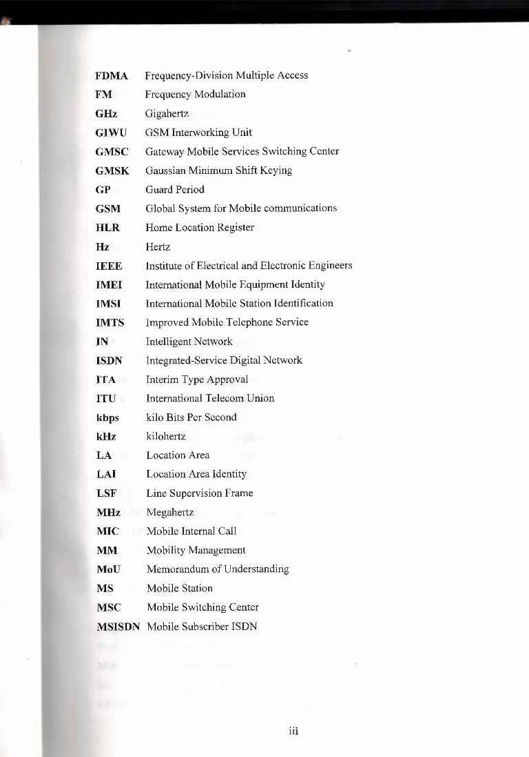


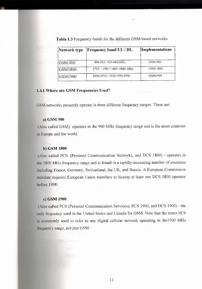


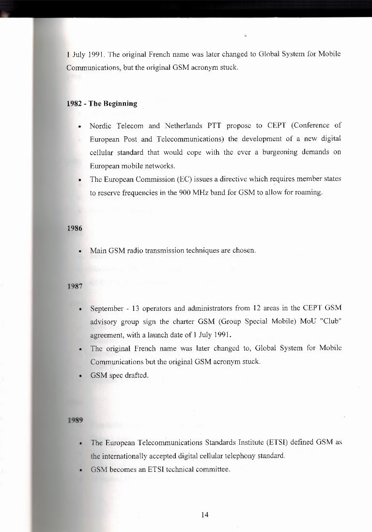

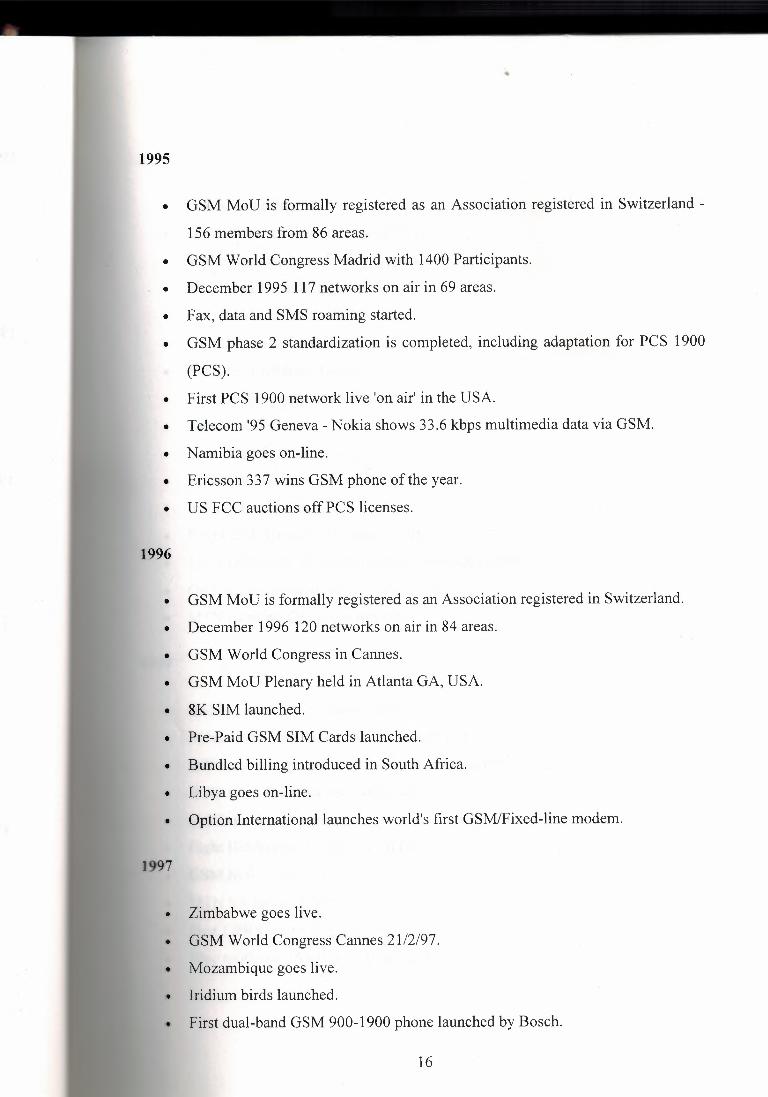
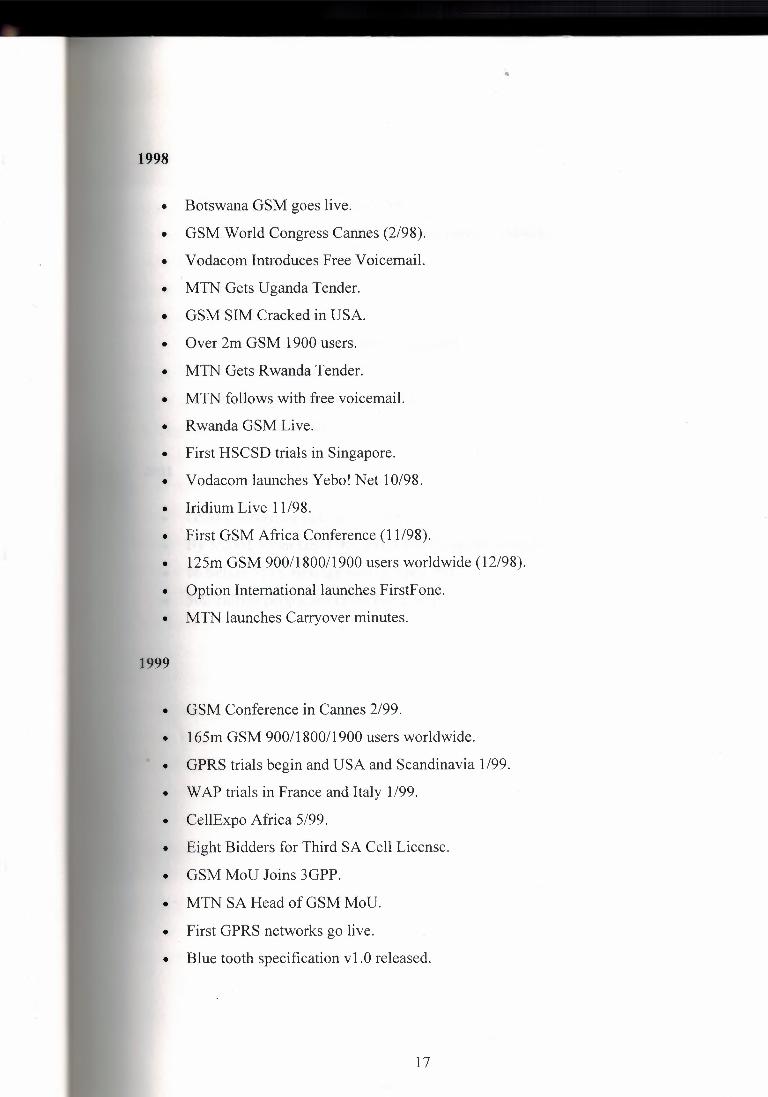


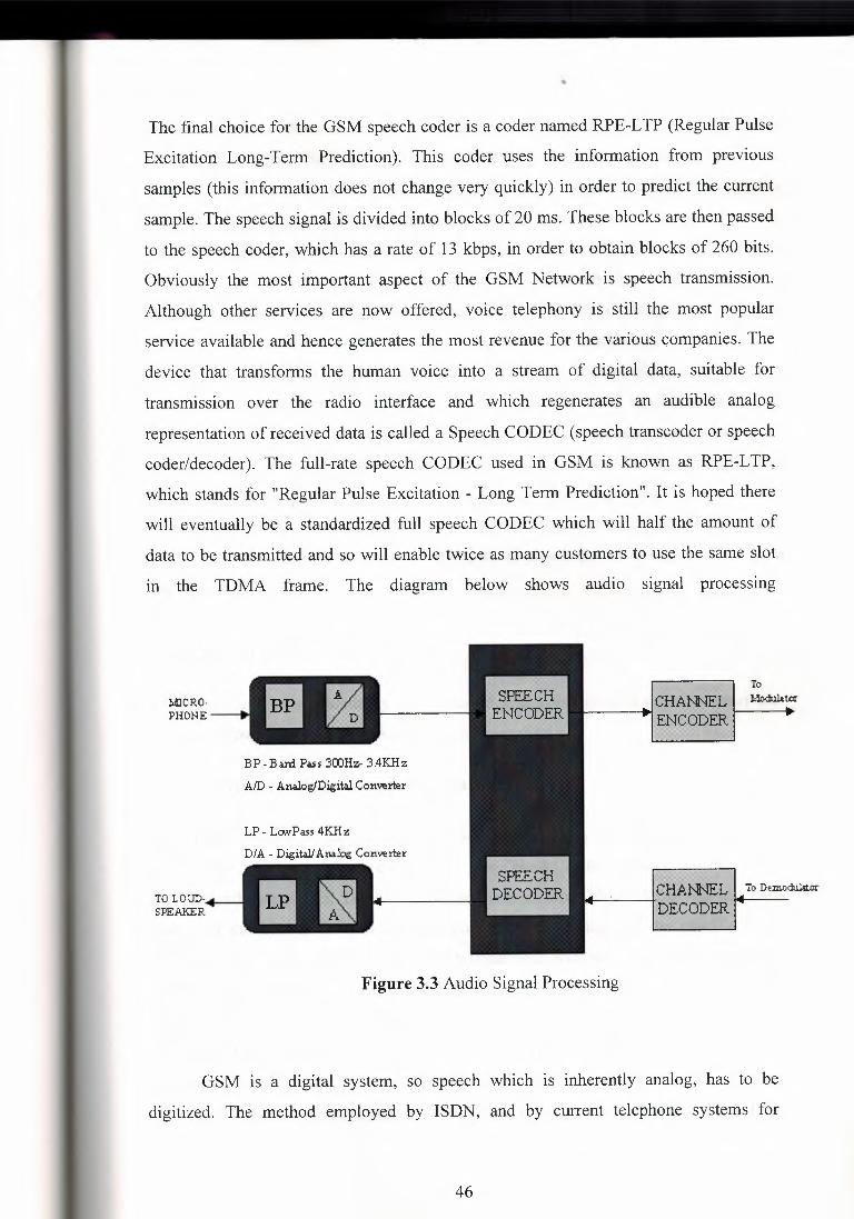


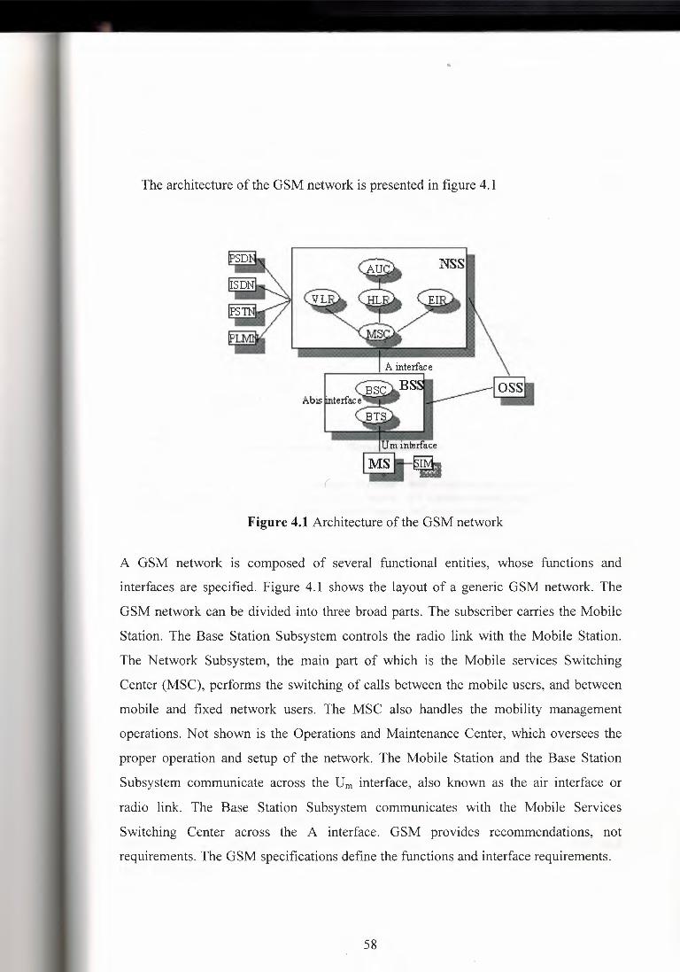


Wl,ı\.~~rııl'I'S.....i ı\]J~~](https://static.documents.pub/doc/80x56/6063d0332f94ab26ab40ccdd/near-east-university-faculty-of-tableofcontents-cliwlrlisi.jpg)


