EUROGRAPHICS 2019A. Giachetti and H. Rushmeier(Guest Editors)
Volume 38 (2019), Number 2STAR – State of The Art Report
Near-Eye Display and Tracking Technologiesfor Virtual and Augmented Reality
G. A. Koulieris1 , K. Aksit2 , M. Stengel2, R. K. Mantiuk3 , K. Mania4 and C. Richardt5
1Durham University, United Kingdom2NVIDIA Corporation, United States of America
3University of Cambridge, United Kingdom4Technical University of Crete, Greece5University of Bath, United Kingdom
Abstract
Virtual and augmented reality (VR/AR) are expected to revolutionise entertainment, healthcare, communication and the manufac-turing industries among many others. Near-eye displays are an enabling vessel for VR/AR applications, which have to tacklemany challenges related to ergonomics, comfort, visual quality and natural interaction. These challenges are related to thecore elements of these near-eye display hardware and tracking technologies. In this state-of-the-art report, we investigate thebackground theory of perception and vision as well as the latest advancements in display engineering and tracking technologies.We begin our discussion by describing the basics of light and image formation. Later, we recount principles of visual perceptionby relating to the human visual system. We provide two structured overviews on state-of-the-art near-eye display and trackingtechnologies involved in such near-eye displays. We conclude by outlining unresolved research questions to inspire the nextgeneration of researchers.
1. Introduction
Near-eye displays are an enabling head-mounted technology thatimmerses the user in a virtual world (VR) or augments the real world(AR) by overlaying digital information, or anything in between onthe spectrum that is becoming known as ‘cross/extended reality’(XR). Near-eye displays respond to head motion and allow for objectmanipulation and interaction. Having recently flooded the market,near-eye displays have the power to create novel experiences thatpotentially revolutionise healthcare, communication, entertainmentand the manufacturing industries among others.
Two notable reviews of VR technologies in the 1990s by twopioneers in the field, Stephen R. Ellis and Frederick P. Brooks,outlined the fundamental challenges that existed back then, which,if solved, would enable the commercial success of XR technolo-gies [Ell94, Bro99]. Although many of these challenges have beenaddressed, including low display cost, high resolution, low latency,6-DoF tracking, complex rendering capability in real time and indus-try leaders entering the field, still, displays suffer from ergonomic,comfort, visual quality and interaction issues. Content for AR/VRis difficult and expensive to produce, and not yet abundant to theaverage non-technical consumer. As Ellis stipulated, because ofunresolved display issues, VR had not yet found the ‘spreadsheet’or ‘killer’ application, which would enable thousands of users tofind solutions to previously intractable problems [Ell94]. What does
it take to go from VR ‘barely working’ as Brooks described VR’stechnological status in 1999, to technologies being seamlessly inte-grated in the everyday lives of the consumer, going from prototypeto production status?
The shortcomings of current near-eye displays stem from both im-perfect tracking technologies as well as the limitations of the displayhardware and rendering algorithms that cannot generate light thatis perceived identically to naturally occurring light patterns. Thisis often the cause of conflicts in the human visual system. The ma-jor difference between traditional computer graphics and near-eyedisplays, is that whereas in computer graphics we often strive forphoto-realism – aiming to render like a camera would capture – innear-eye displays, we aim for a physically correct retinal image,i.e., natural images or perceptual realism. On the bright side, thehuman visual system is also limited, allowing us to exploit theselimitations to engineer displays that are perceptually effective, i.e.,use visual perception as the optimising function for hardware andsoftware design. Such an endeavour demands a multidisciplinary ef-fort to develop novel near-eye display technologies, involving visionscientists, perceptual engineers, as well as software and hardwareengineers.
In this state-of-the-art report, we analyse new advancements indisplay engineering that are driven by a broader understanding ofvision science, which has led to computational displays for near-eye
Koulieris, Aksit, Stengel, Mantiuk, Mania & Richardt / Near-Eye Display and Tracking Technologies for Virtual and Augmented Reality
displays. Today, such displays promise a more realistic and com-fortable experience through techniques such as light-field displays,holographic displays, always-in-focus displays, multiplane displaysand varifocal displays. New optical layouts for see-through compu-tational near-eye displays are presented that are simple, compact,varifocal and provide a wide field of view with clear peripheralvision and large eyebox. Novel see-through rear-projection holo-graphic screens and deformable mirror membranes enabled progresstowards achieving more faithful visual cues. Fundamental trade-offsare established between the quantitative parameters of resolution,field of view and the form factor of the designs – opening an intrigu-ing avenue for future work on accommodation-supporting near-eyedisplays.
We begin our discussion by reviewing principles of visual per-ception, acuity and sensitivity. We then describe the basics of lightgeneration, image formation, wave and geometric optics, and thenrecall fundamental measures such as brightness, contrast, colour,angular/spatial/temporal resolution and dynamic range. We thencontribute two structured overviews: First an examination of basicdisplay types (transmissive, reflective, emissive) and near-eye dis-play technologies (varifocal, multiplane, light-field displays, andholographic). We then review the tracking technologies involved fornear-eye displays (mechanical, magnetic, inertial, acoustic, optical,hybrid) as well as tracking modalities such as head, eye, face/body,hands, multimodal and environment tracking. We conclude by out-lining unsolved problems and challenges for future research.
2. Background
In this section, we provide the necessary background knowledgeon human visual perception, light generation, optics and imageformation relevant to the design of near-eye displays. We discusstracking technologies and modalities as well as their applicationsrelevant to near-eye displays in Section 4.
2.1. The Human Visual System
In this section, we describe the main principles of the human vi-sual system (HVS). A visual stimulus in the environment passesmultiple stages of the HVS before each of these stages determineshow a stimulus is perceived by the user. Briefly, the HVS can bedescribed as an iterative perceptual process (Figure 1) [Gol10b].The process begins with a stimulus enters our eyes, constitutingtwo visual fields, which enables us to process stereoscopic imageryover a field of view that encompasses zones with different stimulisensitivities [WSR∗17]. The optical system focuses the stimuli ontothe retina (the ‘sensor’), which is connected to the visual pathways.This connection transports signals from the eye to the visual cortexin the brain, where the retinal signals are processed. The followingsteps, perception and recognition of the neural signals, allow us tofinally understand what we see. Interestingly, perception (seeingsomething) and recognition (seeing a house) may happen at the sametime or in reversed order [Gol10b]. Finally, the recognized stimulusresults in an action, e,g. approaching the house. In the following, webriefly discuss physiological and perceptual properties of the HVSas well as relevant limitations of vision and perception.
More detailed information on exploiting the HVS for accelerated
Perception Recognition Action
Neural processing
Receptor processes
Light is reflected and focused
Stimulus in the environment
Knowledge
Figure 1: High-level model of the iterative perceptual process. AfterGoldstein [Gol10b].
rendering is given in the recent survey by Weier et al. [WSR∗17].Excellent information about human vision from a physiologicalpoint of view can be found in the book by Adler et al. [LNH∗11].
2.1.1. HVS – Optical Properties
The HVS is characterised by several unique optical qualities that area result of both the position and shape of the eyes. With binocular vi-sion and both eyes looking straight ahead, humans have a horizontalfield of view (FoV) of almost 190°. If eyeball rotation is included,the horizontal FoV extends to 290° [HR95, p. 32]. While the hu-man eye will receive visual stimuli over the full extent of the FoV,the way stimuli are processed in different parts of the visual fieldis highly affected by the spatially varying properties of the retina.There are striking differences between central vision in comparisonto the near and far periphery [CSKH90].
The distance between the pupils, the interpupillary distance (IPD),results in two streams of visual stimuli from slightly different per-spectives, which are combined in the brain by a process called stere-opsis and enables perception of depth also referred to as stereovision [Pal99]. Depth perception is additionally enabled by vi-sual cues such as parallax, occlusion, colour saturation and objectsize [CV95, HCOB10].
The spatial acuity of the HVS is limited by the eye’s optics. It isknown from sampling theory that aliasing occurs if a signal containsfrequencies higher than the observer’s Nyquist frequency [Sha49].In human vision, this undersampling effect occurs for spatial fre-quencies higher than approximately 60 cycles per degree (cpd).Each cycle, also known as line-pair, denotes one black/white linepair taken together [Wan95, p. 24]. However, the eye’s optics inthe cornea and lens act as a low-pass filter with a cutoff frequencyaround 60 cpd. This way, the signal that cannot be properly sampledand reconstructed is effectively removed through optical prefiltering.
The pupil is an additional important factor. With its adjustablediameter of 2 to 8 mm [Gol10a], it serves as an aperture. This adjust-ment mostly affects the sharpness of the image, as only about onemagnitude of light intensity difference (1 log unit) can be controlledby the pupil. The eye’s adaptation to differences in brightness sensa-tion (dark and light adaptation) mostly takes place on the retina.
Light that enters through the eye is projected onto the retina, thephotosensitive layer of the eye. This layer consists of two typesof photoreceptors: 6 · 106 cones and approximately 20 times asmany rods [Gol10b, p. 28]. Rods consist of only one type of light-sensitive pigment and are responsible for the brightness sensationin lower-light conditions (scotopic vision) by providing monochro-matic feedback. Cones are divided into three types for different wave-lengths, namely L-cones (long wavelengths), M-cones (mediumwavelengths) and S-cones (short wavelengths). They are respon-sible for sensing colour and details in bright conditions (photopicvision). Photoreceptors of different types follow the distributionpattern shown in Figure 2. The central area of the retina, the fovea(approx. 5.2° around the central optical axis), consists entirely ofcones. Cone density drops significantly with increasing eccentric-ities (the angular distance to the optical axis) [CSKH90] past theparafovea (approx. 5.2° to 9°) and perifovea (approx. 9° to 17°).These inner parts constitute central vision, while areas further awayare referred to as peripheral vision. The highest density of rods isapproximately 15–20° around the fovea. Their density drops almostlinearly. Just as the rods and cones have different densities across theretina, they have different spatial sampling distributions and follow aPoisson-disc distribution pattern [Yel83, Wan95, ch. 3]. The densityof cones is related to visual acuity, the “keenness of sight”. Thevisual acuity of the eye drops significantly outside the small fovealregion, where humans are able to generate a sharp image (acuityis already reduced by 75% at an eccentricity of 6°). Visual acuitycan be expressed as minimum angle of resolution (MAR). Normalvision corresponds to 1 MAR, a measure describing that a featuresize of 0.5 minutes of arc is still visible [LNH∗11, p. 627]. Thisminimal feature size relates to a spatial frequency of a sinusoidalgrating pattern of alternating black and white spaces at 60 cpd.
There are further factors influencing this keenness of sight. Vi-sual acuity also depends on the contrast of the stimuli. The acuitylimit is usually measured using a high-contrast image or a letterunder photopic luminance conditions, which corresponds to typicaldaylight and display use cases. Moreover, the reduction of acuitydepends on the overall lighting. Under dimmed light, the perceivable
4 8 0.125 0.25 0.5 1 2
Spatial frequency [cpd]
1
3
10
30
100
Se
nsitiv
ity (
L/
L)
Lb=100 cd/m
2
Lb=10 cd/m
2
Lb=1 cd/m
2
Lb=0.1 cd/m
2
Lb=0.01 cd/m
2
Lb=0.001 cd/m
2
0.001 0.01 0.1 1 10 100
Luminance [cd/m2]
1
3
10
30
100
f=0.25 cpd
f=0.5 cpd
f=1 cpd
f=2 cpd
f=4 cpd
f=8 cpd
Figure 3: Contrast Sensitivity as a function of spatial frequency (left)and luminance (right). The plot is based on Barten’s model [Bar04].
spatial detail is reduced. The highest perceivable spatial frequencyof a sinusoidal grating pattern reduces from ~60 cpd at photopiclevels down to ~2 cpd for scotopic vision. In addition, contrast per-ception is affected [BSA91]. The eye’s sensitivity to contrast canbe described by a contrast sensitivity function (CSF). The CSFdescribes the change in sensitivity as a function of stimulus size,background luminance, spatial frequency, orientation and temporalfrequency. The CSF separately describes achromatic (luminance)and chromatic mechanisms ([L-M] and [S-(L+M)]). The CSF isdefined as the reciprocal of the smallest visible contrast. The mea-surements are usually performed using sinusoidal grating patternsat different contrast levels. Figure 3 shows the variation in spatialfrequency as a function of spatial frequency and luminance, respec-tively. The region under the curve is commonly called the windowof visibility [LNH∗11, pp. 613–621]. The resolvable acuity limit of(60 cpd) corresponds to the lowest contrast sensitivity value. Veryhigh (>60 cpd) and very low frequencies (<0.1 cpd) cannot be per-ceived at all. While the upper limit can be explained by the conespacing and optical filtering, the lower limit cannot be directly de-rived from the eye’s physiology [LNH∗11, pp. 613–621]. Contrastsensitivity depends on the number of neural cells responding to therespective grating pattern [RVN78]. From the fovea to the periphery,sensitivity decreases significantly at all frequencies. The decrease isfastest for high frequencies [RVN78].
The varying distributions of rods and cones also affect the sen-sitivity to colours in different parts of the visual field [NKOE83].The fovea is dominated by the cones sensitive to long and mediumwavelength and capable of distinguishing between red and greencolours. In contrast, only about 9% of our cones are responsiblefor the perception of short wavelengths, but they are more spreadoutside the fovea. This leads to a relatively higher sensitivity to bluecolours in the periphery. Hence, contrast sensitivity also dependson the chromaticity of the stimulus. Blue/yellow and achromaticstimuli result in a less-pronounced decrease in terms of contrastthreshold [Mul85]. The sensitivity to red–green colour variationsdecreases more steeply toward the periphery than the sensitivityto luminance or blue-yellow colours. Besides the different densi-ties of the cones, neural processes are also of importance in thiscontext [HPG09].
Retinal photoreceptors have the ability to adapt to stark changes
Koulieris, Aksit, Stengel, Mantiuk, Mania & Richardt / Near-Eye Display and Tracking Technologies for Virtual and Augmented Reality
in light intensity. While adaptation to bright lighting can occurvery rapidly, adapting to low lighting conditions takes considerablylonger [Ade82,Bak49]. Adaptation influences the performance ofthe HVS, such as colour perception, spatio-temporal contrast sensi-tivity and the amount of perceivable detail [VMGM15, LSC04]. Itenables humans to perceive visual information robustly over sevenorders of magnitude of brightness intensities. However, we are notable to see equally well at all intensity levels: At lower light levels,due to rod-vision, acuity is reduced. During daytime, contrast sensi-tivity is lower, but visual acuity and colour vision excel. Similar tothe drop of acuity with eccentricity that can be observed in stereopsis,depth perception is significantly reduced in the periphery [PR98].
2.1.3. HVS – Motor
Our eyes are constantly in motion. Six external muscles (the ex-traocular muscles) allow precise and fast changes of the horizontaland vertical orientation of the eye as well as torsional movementsthat bring the top of the eye toward the nose (intorsion) or awayfrom the nose (extorsion). The primary goal of moving the eyes is tomove the projection of the object of interest onto both foveæ, so thatthe focused object is perceived with high detail. The most impor-tant types of motion are saccades, fixations, vestibulo-ocular reflex,smooth pursuit eye motion, and coupled vergence–accommodationmotion. An excellent survey on the properties and effects of humaneye motion from a psychophysical point of view is provided byKowler [Kow11].
Saccades are the result of eye motion rapidly jumping from one re-gion of interest to another. During a saccade, peak angular speeds ofup to 900°/s [FR84] can be reached. Preceding the beginning of eyemovement, there is a dramatic decline in visual sensitivity, which isreferred to as saccadic suppression [VRWM78,WDW99,RMGB01].As a result, during saccadic eye movements, accurate visual infor-mation cannot be acquired. In contrast, fixations describe the stateand duration in which visual information is perceived while ourgaze remains close to an object of interest. Fixation durations typi-cally vary between 100 milliseconds and 1.5 seconds [WDW99]. Itis assumed that the duration of a fixation corresponds to the rela-tive importance and visual complexity of an area in the visual field.When viewing a typical natural scene, the HVS triggers aroundtwo to three saccades per second, and the average fixation timeis about 250 milliseconds [KFSW09]. The spacing between fixa-tions is, on average, around 7° of viewing angle. The unconsciouslytriggered tracking reflex when a moving object attracts our gazeis called smooth pursuit eye motion (SPEM). This motion enablesthe observer to track slow-moving targets so that the object is fix-ated onto the fovea. Interestingly, small eye movements up to 2.5°/shave hardly any effect on visual acuity [LNH∗11]. However, thesuccess rate depends on the speed of the target and decreases sig-nificantly for angular velocities in excess of 30°/s. Saccades aregenerally driven by position error, and smooth pursuit, generally,by velocity error. Both types of movements are generally binocularand involve both eyes rotating in the same direction. The eye is nota camera; the visual percept of a stable surround visual world isa perceptual construction of very small high-resolution snapshotsand is due to a large degree to pervasive unconscious perceptualfilling-in processes.
Stereopsis is highly entangled by vergence and accommodation.
In order to fixate an object, both eyes are required to simultane-ously rotate in opposite directions (vergence). Accommodation isthe mechanical ability of the eye to change the shape of the lensso one can focus at different distances [How12]. When the ciliarymuscles at the front of the eye tighten, the curvature of the lensand, correspondingly, its focusing power is increased. Accommo-dation describes the natural counterpart of adjusting a camera lensso that an object in the scene is set into focus. Importantly, thisprocess happens unconsciously and without any effort in less than asecond at photopic illumination levels [Gol10a, p. 289]. Typically,stereoscopic displays drive vergence by providing binocular dispar-ity cues using a separate image for each eye. Yet, as the imagesare shown on the screen, the eyes focus on the screen’s distance.This can result in a conflict, known as the vergence–accommodationconflict [Gol10a, p. 1040]. Accommodation and vergence motionsare coupled with the fixation process for binocular vision so thatboth eyes’ gaze aims at the same point at which they focus.
2.1.4. HVS – Cortical processing
Retinal stimuli processing is followed by neural information pro-cessing in the visual cortex of the brain. Corresponding to the dropin the density of rods and cones, over 30% of the primary visualcortex are responsible for the central 5° of the visual field, whilethe periphery is under-represented [HH91]. Cognitive processing ofimages and perceptual differences between central and peripheralvision have been targeted by perception research. Thorpe et al. haveshown that peripheral vision provides a rich source of information,crucial to the perception and recognition of contrast features, objectsand animals [TGFTB01]. Furthermore, the HVS makes extensiveuse of contextual information from peripheral vision, facilitatingobject search in natural scenes [KKK∗14]. Thereby, pre-processingof visual stimuli probably occurs. There is evidence that basic vi-sual features (such as object size, colour and orientation) are pre-processed before actual attention is placed on the object by movingit into central vision [WB97]. Besides the process of stereopsis, theability to interpret depth cues in the visual input to improve stereovision and the sense of spatial localisation is highly entangled in thevisual cortex.
Finally, vision is affected by cross-modal effects. In particular,VR systems often provide non-visual cues such as audio, vibrationor even smell. These effects have been studied in psychologicalexperiments on various interplays between cues [SS01, Pai05, SS03,WP04]. When sensory channels are substituted or combined, someimplications occur: sensory channels are no longer seen as separatechannels, but may affect each other through integration of sensorysignals inside multimodal association areas in the brain [Pai05,LN07, Sut02, pp. 36–64].
2.1.5. HVS – Memory and Attention
The processing of visual information is highly dependent on knowl-edge and patterns stored in memory [KDCM15]. How such knowl-edge is stored is still a topic of fundamental research [SK07].
While attention is still not fully understood, research indicatesthat it has three components: (1) orienting to sensory events, (2)detecting signals for focused processing, and (3) maintaining a vig-ilant or alert state [PB71]. Attention is important for processing
Koulieris, Aksit, Stengel, Mantiuk, Mania & Richardt / Near-Eye Display and Tracking Technologies for Virtual and Augmented Reality
visual stimuli and search behaviour [TG80]. It involves the selectionof information for further processing and inhibiting other informa-tion from receiving further processing [SK07, p. 115]. Attentioncan occur in information-processing tasks in various ways [WC97]:selective attention is the choosing of which events or stimuli toprocess; focused attention is the effort in maintaining processingof these elements while avoiding distraction from other events orstimuli; divided attention is the ability to process more than oneevent or stimulus at a given point in time.
Being aware of the limitations of the human visual system enablesus to avoid under- or over-engineering near-eye displays. In thefollowing sections, we explore the theory that drives design choicesin near-eye displays.
2.2. Light Generation
In this section, we examine the basic properties of light that con-tribute to image formation. Light can be modelled either as anelectromagnetic wave or a stream of photons. In this state-of-the-artreport, we focus on the wave nature of light that is more relevantto near-eye displays. When modelled as an electromagnetic wave,most forms of light generation relate to rapidly moving electricalcharges consequently generating electromagnetic waves. Electro-magnetic waves are self-propagating waves of intermittent electricand magnetic fields that carry energy, cyclically exchanged betweenthe electric and magnetic components [YFF07]. The rate of ex-change is the light frequency. A select range of frequencies, calledthe spectrum, can be perceived by the human eyes and is knownas visible light. The wavelength λ of these frequencies relates tofrequency via the equation λ = c/ f , where c is the speed of light invacuum and f is frequency. Visible light ranges from wavelengthsof 380–780 nm or frequencies in the 1015 Hz range. Wavelengthand amplitude of the light wave correspond to perceived colour andintensity, respectively [Pal99].
Forms of light generation include single charges, such as elec-trons, giving birth to photons. Electrons that change orbits in anatom release the positive energy difference as photons. This happensin semiconductors, such as light-emitting diodes (LEDs), where ma-terial properties define specific energy levels (bands) between whichthe electrons jump, generating light of specific wavelengths [MS08].Another form of light emission is thermal emission, caused bythe motion of atoms in solids, liquids and gases. Thermal emis-sion usually contains photons spanning a wide range of energies,e.g., tungsten lamps [Pla13]. In the majority of VR/AR headsets,the modulated light is generated using LEDs and OLEDs (organicLEDs) [HB16].
LEDs are semiconductor chips selectively enriched with othermaterial impurities (doped) to create a p–n junction, i.e., an interfacebetween two types of semiconductors: one positive (p-side) andone negative (n-type) [MS08]. The p-side contains an excess ofelectron holes, while the n-side contains an excess of electronsenforcing the electrical current to pass through the junction only inone direction. Electron holes and electrons flow into the junction andwhen an electron meets a hole, the electron falls into a lower energylevel, thus releasing energy in the form of a photon. LEDs are usedboth as a display backlight, in headsets that employ transmissive
liquid-crystal displays (LCDs), or directly integrated into silicon asindividually addressable LED pixels in micro-LED displays [HB16].Contrary to LEDs, OLEDs employ a thin film of organic compoundthat directly emits light in response to an electric current runningthrough the electroluminescent layer [DF04]. Both micro-LED andOLED-based displays are expected to become affordable in theyears to come.
2.3. Optics Principles
To make use of light in the context of a display, it has to be formedby optics. Depending on the phenomenon that we try to explain orexploit, we can formulate light travel and interactions as a wave inwave optics or simpler, as rays travelling in space using geometricoptics.
Wave Optics Light as a wave is characterised by a particularwavelength, amplitude and phase [Goo17]. If two waves of the samefrequency are in phase they are called coherent. Light consistingof one wavelength is called monochromatic. A consequence of thatis that coherent light must also be monochromatic. Points of equalphase form a surface which is called a wavefront. The wavefrontis spherical if waves are emitted from a point. If light is emittedfrom an infinite number of points on a plane, the wavefront consistsof infinite planes that are orthogonal to the propagation direction,and is called a planar wavefront. Any complex wavefront can beformed from a collection of multiple virtual point sources and theirspherical wavefronts. When a wavefront encounters an obstacle,the virtual point sources next to the obstacle’s border transmit lightbehind the obstacle, a phenomenon known as diffraction [Luc06].Diffraction depends on wavelength, as larger wavelengths diffractmore [YFF07].
Geometric Optics When image points are far larger than the wave-length of light, geometric optics is typically considered. Geometricoptics provide an abstraction that formulates light as travelling alongstraight lines (a.k.a. ray tracing), ignoring its wave nature. Geomet-ric optics can describe simple optical elements, such as lenses, andgeometric phenomena, such as reflection. Depending on materialproperties, light can be reflected, refracted, scattered, absorbed ordiffracted by matter. For the purpose of this report, we will brieflydiscuss refraction and reflection. We refer the curious reader to moreadvanced books on the topic [YFF07, HB16].
Light changes direction when passing a border between two me-dia of different optical densities due to the difference in speed oftravel through these media, a phenomenon that is known as refrac-tion. Let us consider a beam whose wavefront is perpendicular tothe way of travel. When that beam of light meets the border of twodifferent optical media, the edge of the wavefront that first entersthe second medium and experiences a delay until the second edgealso enters the medium, which causes a change in the wavefrontangle, similarly to when a car moving from a pavement to mud at anangle, will rotate along its vertical axis. This happens because thefirst wheel will spin slower till the second wheel also reaches themud. The amount of refraction depends on wavelength. The angleof deflection can be estimated using Snell’s law for geometric op-tics [YFF07]. Short wavelengths travel slower in denser media, and
Koulieris, Aksit, Stengel, Mantiuk, Mania & Richardt / Near-Eye Display and Tracking Technologies for Virtual and Augmented Reality
as such experience stronger diffraction – a phenomenon explainingwhy a glass prism disperses light into its spectral components. Onthe border of two materials, not all light is refracted. Some of itis always reflected and is polarised perpendicularly to the deflec-tion angle. This partial light reflection at media boundaries can becalculated using the Fresnel equations [HB16].
The principles of most optical-image generation that is happen-ing in near-eye displays heavily rely on geometric optics phenom-ena, such as refraction and reflection. For explaining holograms,though, a wave representation is needed. A detailed image forma-tion model for the setting of holographic projection displays hasbeen derived [PDSH17]. A model that includes diffractive lightpropagation and wavelength-dependent effects has also been pro-posed [SDP∗18].
2.4. Image Formation
In this section, we explain fundamental display measures such asspatial, angular and temporal resolution, intensity, contrast and dy-namic range. Most near-eye displays update information that isdisplayed in a raster-scanning fashion, reproducing pictures as amatrix of pixels arranged on a rectangular grid [HB16]. The imageis formed by setting these pixels to different colours and intensities.The number and size of pixels in a given area of the screen deter-mines the amount of information that can be displayed. The pixelsize, and consequently pixel density, restricts the maximum size adisplay can have before its pixels can be individually discerned.
The viewing angle a single pixel occupies denotes the angular res-olution of the display, which is of particular importance for near-eyedisplays. Human visual acuity can reach up to 60 cpd [Pal99], i.e.,120 pixels would be needed per degree of visual angle for them to beindiscernible. The temporal resolution of the display (refresh rate)denotes how many times per second a new image is drawn on thedisplay. For near-eye displays, a refresh rate of ~90 Hz is desirableto eliminate flickering, especially in the periphery [TFCRS16].
Another essential display parameter is peak luminance, which ismeasured in cd/m2. The perceived brightness of a display dependson the energy emitted, the emission spectrum and the size of theimage, among others. As the human visual system adapts to theoverall intensity of a scene, display intensity levels should be atleast as high as the display surroundings. If not, the image willappear faint and lacking contrast. In the real world, intensity levelsspan from 10−6 cd/m2 up to 108 cd/m2, a dynamic range of 14orders of magnitude [MDMS05]. In headsets, display intensitiesusually span two to three orders of magnitude due to technicallimitations, light reflections inside the headset or over the lens,etc. Dynamic range is especially problematic when liquid-crystaldisplays (LCDs) are employed, as the polarisers used in them alwaysleak a small amount of light coming from the backlight [HB16].High dynamic range (HDR) displays increase the span of displayableintensities, often by employing multiple spatial light modulators(SLM) stacked in series. For example, stacking an addressable LCDover an addressable LED display, usually of much lower resolution,allows for double modulation of light, increasing the bit depth ofthe output and achievable contrast [MMS15].
Most current headsets use 8-bit displays, which corresponds to
256 greyscale levels. Insufficient colour bit-depth often leads to visi-ble brightness steps that are known as banding/contouring artefactsin areas that should otherwise appear smooth, an effect accentuatedby the eyes’ inherent contrast enhancement mechanisms [Rat65].Displays’ colour reproduction capabilities can be measured by defin-ing their colour gamut [TFCRS16]. By marking the red, green andblue colour primaries used in a display on a chromaticity diagramand then joining those primary locations, the achievable colourgamut can be visualised [HB16]. Achieving wide colour gamutsrequires narrow-band primaries (spectral) near the edges of thechromaticity diagram [TFCRS16].
2.5. 2D Spatial Light Modulators
The core component of any electronic display is a spatial lightmodulator (SLM), which controls the amount of light transmittedor emitted at different spatial positions and at a given instance oftime. Here, we focus on SLMs that are commonly used in VR/ARdisplays: liquid-crystal displays (LCDs), liquid crystal on silicondisplays (LCoS), and active-matrix organic light-emitting diodedisplays (AMOLED) [HB16].
While VR/AR tracking sensors often operate at 1000 Hz, thedisplay refresh rates and response times are often much lower. Forthat reason, the most critical display characteristics in AR/VR areits temporal response and the quality of reproduced motion. Themain types of artefacts arising from motion shown on a display canbe divided into: (1) non-smooth motion, (2) false multiple edges(ghosting), (3) spatial blur of moving objects or regions, and (4)flickering. The visibility of such artefacts increases for reducedframe rate, increased luminance, higher speed of motion, increasedcontrast and lower spatial frequencies [DXCZ15]. To minimisemotion artefacts, VR/AR displays often operate at higher framerates and lower peak-luminance levels, and incorporate techniquesthat mask some of the motion artefacts.
LCDs rely on a transmissive SLM technology, in which a uniformbacklight is selectively blocked to produce an image. The name ofthe technology comes from nematic liquid crystals, which formelongated molecules and can alter the polarisation of the light. Theliquid-crystal molecules are trapped inside a sandwich of layersconsisting of glass plates and polarisers. When an electric fieldis applied to the sides of the glass, the molecules change theiralignment and alter the polarisation of the light, so that more orless light passing through the display is blocked by the polarisers.LCD is the dominant display technology at the moment, which hasbranched into numerous sub-types, such as twisted nematic (TN),multidomain vertical alignment (MVA), or in-plane switching (IPS).Those sub-types compete with each other in price, the quality ofcolour reproduction, viewing angles and dynamic range.
LCoS is another important technology based on liquid crystals,which can be found in projectors, but also some AR displays, suchas the Microsoft HoloLens or the Magic Leap One. In contrast toLCDs, which modulate transmitted light, LCoS displays modulatereflected light. This is achieved by giving a reflective surface to aCMOS chip, which is then layered with liquid crystals, an electrodeand a glass substrate. The light is typically polarised with a polar-ising beam-splitter prism, and colour is produced by sequentially
Koulieris, Aksit, Stengel, Mantiuk, Mania & Richardt / Near-Eye Display and Tracking Technologies for Virtual and Augmented Reality
Lum
inan
ceV
olta
ge
Target level
Actual level
Driving signal
t
(a)(b)
(c)
Full brightness
Dimmed
Inte
nsit
yIn
tens
ity
Figure 4: (a) Delayed response of an LCD, driven by a signal withoverdrive. The plot is for illustrative purposes and does not representmeasurements. (b) Measurement of an LCD (Dell Inspiron 17R7720) at full brightness and when dimmed, showing all-white pixelsin both cases. (c) Measurement of an HTC Vive display showingall-white pixels. Measurements taken with a 9 kHz irradiance sensor.
displaying images (fields) of different colours. Compared to LCDtechnology, LCoS SLMs are easier to manufacture, can achievehigher resolutions and can be made smaller. These are all desirableproperties for any wearable near-eye display.
The liquid crystals found in the recent generation of LCDs andLCoS chips have relatively short response times and offer refreshrates of 120–240 Hz. However, liquid crystals still require timeto switch from one state to another, and the desired target stateis often not reached within the time allocated for a single frame.This problem is partially alleviated by over-driving (applying highervoltage), so that pixels achieve the desired state faster, as illustratedin Figure 4(a).
AMOLED displays are SLMs that emit light themselves whena voltage is applied. This brings many advantages, such as veryhigh contrast (dynamic range), highly saturated (pure) colours, wideviewing angles, fewer components and thinner displays, as there isno need for a backlight or other light source. One of the remainingproblems is the difficulty in driving AMOLED displays at highbrightness when pixels are small (due to peak-current tolerance).They also tend to be more expensive to manufacture. However, thebiggest advantage of AMOLED displays in VR/AR applicationsis their instantaneous response time. For that reason, AMOLED isthe technology of choice for high-quality VR headsets, includingHTC Vive and Oculus Rift, but also smartphones supporting GoogleDaydream headsets.
2.6. Motion Quality
While it may seem that fast response times should ensure goodmotion quality, response time accounts only for a small amount ofthe blur visible on LCD and AMOLED screens. Most of the bluris attributed to eye motion over an image that remains static forthe duration of a frame [Fen06]. When the eye follows a movingobject, the gaze smoothly moves over pixels that do not changeover the duration of the frame. This introduces blur in the imagethat is integrated on the retina – an effect known as hold-type blur.
Hold-type blur can be reduced by shortening the time pixels areswitched on, either by flashing the backlight [Fen06], or by insertingblack frames (BFI). These techniques are known in the context ofVR/AR displays as a low-persistence mode, in which pixels areswitched on for only a small portion of a frame. Figure 4(c) showsthe measurements of the temporal response for an HTC Vive headset,which indicates that the display remains black for 80% of a frame.The low-persistence mode also reduces the lag between the sensorsand the display, as it shows only the first few milliseconds of a frame,for which the head-pose estimation is the most accurate. It shouldbe noted that all techniques relying on rapidly switching the displayon and off reduce the peak luminance of the display, and may alsoresult in visible flicker.
See-Through Screens Researchers have explored see-throughscreen designs based on classical optical components. Hedili etal. [HFU13] describe a see-through microlens array for a heads-up display application. Soomro and Urey [SU16] report a see-through screen based on retro-reflectors for a head-mounted projec-tion display application. Neither of these approaches has yet beenredesigned for near-eye displays, nor for the expected diffractioneffects accompanying that miniaturisation. Using silver nanoparti-cles and a front projector, Hsu et al. [HZQ∗14] create a transparentscreen that backscatters light at specific wavelengths. Yamamoto etal. [YYN∗16] also describe a different approach to a wavelength-selective front-projection transparent screen using cholesteric liquid-crystal dots.
Curved and Freeform Screens Researchers have exploreddesktop-sized static, curved displays [WVSB10, HWC∗17, BWB08,BKV11, KM15] and large-format, immersive, static curved dis-plays [KLT∗09, HKMA07, BW10, TNSMP17]. These displays aretypically cylindrical or spherical in their surface profile. The workof Brockmeyer et al. [BPH13] demonstrated a static desktop-sizeddisplay. Researchers have also shown manually configurable flex-ible displays that use organic LEDs [YJK∗10], thin electrolumi-nescent films [OWS14], and electronic-ink [GHM∗06]. Recently,a dynamically shape-changing display was demonstrated by Lei-thinger et al. [LFOI15]. For a more exhaustive survey on non-planar displays, we refer interested readers to the following pa-pers: [ARS∗18, LKKC17, RPPH12].
3. Immersive Near-Eye Display Technologies
Augmented reality and virtual reality using optical near-eye displays(NEDs) promise to be the next breakthrough mobile platform, pro-viding a gateway to countless AR applications that will improveour day-to-day lives [BKLP04, vKP10]. Although most emergingconsumer products are being advertised for gaming and entertain-ment applications, near-eye display technology provides benefits forsociety at large by providing a next-generation platform for educa-tion, collaborative work, teleconferencing, scientific visualisation,remote-controlled vehicles, training and simulation, basic visionresearch, phobia treatment, and surgical training [HS14]. For exam-ple, immersive VR has been demonstrated to be effective at treatingpost-traumatic stress disorder (PTSD) [DH02], and it is an integralcomponent of modern, minimally invasive surgery systems, suchas the da Vinci surgical system. Eye movement desensitization and
Koulieris, Aksit, Stengel, Mantiuk, Mania & Richardt / Near-Eye Display and Tracking Technologies for Virtual and Augmented Reality
reprocessing has been shown by systematic clinical trials to also beeffective for the treatment of PTSD, often combined with immer-sive VR [CLvdHE16]. We first review near-eye display optics inSection 3.1, in which we introduce the necessary optics terminologyin Section 3.1.1, and also review optical designs both for VR andAR applications in Section 3.1.2 and Section 3.1.3, respectively. Wededicate Section 3.2 to accommodation-supporting near-eye displaytechnologies. As an important emerging problem, we also providea detailed overview of foveated displays in Section 3.3, and anoverview of vision correction for near-eye displays in Section 3.4.
3.1. Near-Eye Display Optics
To fulfill the promise of immersive and natural-looking scenes,as described by Kress and Sterner [KS13b], designers of AR andVR NEDs need to solve difficult optical design challenges, includ-ing providing sufficient resolution levels, eyebox and field of view(FoV). A major impediment to achieving natural images, and akey cause of discomfort, is the vergence–accommodation conflict(VAC) [HGAB08, JPK∗16, KBBD17], which is caused by a mis-match between the binocular disparity of a stereoscopic image andthe optical focus cues provided by the display (see discussion inSection 2.1.3). Mainstream strategies [Hua17] for tackling thesechallenges involve dynamic display mechanisms that can generateaccurate visuals at all possible optical depths, which greatly in-creases the complexity of the NED design problem. Other obstaclesto widespread adoption of AR NEDs include providing affordabil-ity, requiring a reasonable amount of computation and power, andproviding a thin and lightweight form factor suitable for daily use.All of these problems are still waiting to be solved and even smallsteps towards a possible solution require a massive effort.
3.1.1. Near-Eye Display Optics Terminology
To provide a base for our review on optical NED technologies,we first summarise common optics terminology. The location ofa depth plane (virtual image) generated by a near-eye display istypically reported in diopters, D, which corresponds to the recip-rocal of the focus distance in meters (D = 1
meters ). Many standardsexist for reporting binocular FoV, including starting from a specificpoint inside a person’s head or starting from a “cyclopean eye” be-tween the user’s eyes (e.g., [WDK93]). Especially in the case ofaccommodation-supporting NEDs, the differing assumptions lead towidely varying estimates of the binocular FoV, and so we report onlythe well-understood measure of monocular FoV, which is typicallyreported in degrees. Resolution of a NED is quantified using cyclesper degree (cpd). For a specific depth plane and visual field (por-tion of a FoV), typically cpd is reported in arcmins, which is 1/60degrees. The eyebox of a NED can be defined either as a volumeor a plane, where the user’s eye can be located in front of a NED.Eyebox dimensions are typically reported in millimetres.
3.1.2. Near-Eye Display Optics for Virtual Reality
In the early 1800s, David Brewster introduced a hand-held stereo-scope [Bre56] using a pair of photographs and a pair of magnifyingglasses. Following Brewster’s optical layout, today’s most commoncommercially available near-eye displays employ a small screenand an optical relay to project light from the screen onto the user’s
Figure 5: Diagrams showing various optical layouts for near-eyedisplays.
retinas, creating a magnified virtual version of the screen at a fixeddepth. Some of these displays are made to be video see-through ARsystems by displaying a view of the real world captured through anon-board camera [RF00]. In the next section, we review the opticsof see-through near-eye displays that are illustrated in Figure 5.
Koulieris, Aksit, Stengel, Mantiuk, Mania & Richardt / Near-Eye Display and Tracking Technologies for Virtual and Augmented Reality
3.1.3. See-Through Near-Eye Display Optics
Sutherland [Sut68] introduced see-through NEDs using a beamcombiner near the eye of a subject to superimpose the direct viewof the real world and computer-generated images. Optical systemsrelying on flat combiners have progressed greatly as described byRotier [Rot89] and Cakmakci and Rolland [CR06]. The geometryof flat beam combiners along with the lenses used in optical NEDsdictates a strict trade-off: a large FoV quickly leads to a bulky formfactor. Droessler and Rotier [DR90] propose a tilted catadioptric(reflecting and refracting) system to overcome FoV limitations bytilting the optics with respect to a flat combiner, and using a curvedcombiner as the final relay surface, which provides up to 60° ofrotationally symmetrical monocular FoV. Tilted catadioptric systemsare fundamentally limited in light efficiency, depend on a complexpolarised optical system, and produce a bulky form factor. Gilboaproposes an off-axis single-element curved beam combiner [Gil91],and explores the associated optical design space. Today, modernvariants of off-axis single-element curved beam combiners (e.g.,Wang et al. [WLX16]) are deployed in military applications andconsumer-level prototypes (e.g., Meta 2). Major limitations in off-axis single-element curved beam combiners come into play whileextending FoV in horizontal directions when lit vertically; thesecombiners are known to provide poor imaging characteristics witheccentricity, and require a larger screen with a larger FoV demand.
Another family of see-through NEDs is based on waveguides.Cheng et al. [CWHT09] propose a waveguide-based NED designthat fuses curved beam combiners and waveguides into a singlefree-form prism. They describe a tiling strategy of these prisms to in-crease limited FoV, which requires multiple displays per prism. Flatcombiners have been converted into thin cascaded waveguides as asee-through NED prototype (e.g., Lumus); however, FoV-related is-sues are still a major problem in practice. As described by Kress andShin [KS13a], holographic methods simplify designing waveguidesthrough holographic out-coupling and in-coupling of light. Today,such displays are present as consumer-level see-through NED pro-totypes (e.g., Microsoft HoloLens, Magic Leap One, Sony SmartEye), which only report a maximum of 45° diagonal binocular FoV.Holographic optical elements (HOEs) can function as a completereflective and diffusive beam combiner, as demonstrated by Li etal. [LLJ∗16] and Maimone et al. [MGK17], with a small eyebox.
Retinal scanning displays propose to address each cell on a user’sretina with a beam of light. Johnston et al. [JW95] first proposeda retinal-scanning NED by using laser light sources with a Micro-Electromechanical System (MEMS) scanner, which was later com-mercialized as well (Microvision Nomad). The eyebox generated bya retinal scanning NED is proportional to the size of the used mir-ror in the scanner, which therefore typically limit this aspect. Mostrecent developments in retinal NEDs were reviewed by Rolland etal. [RTB∗16].
3.2. Accommodation-Supporting Near-Eye Displays
Accommodation-supporting NEDs [Hua17, Kra16] address the ver-gence–accommodation conflict (VAC) by matching the binocu-lar disparity of virtual objects with correct optical focal cues forvarious depth planes. Figure 6 compares the optical layouts of
accommodation-supporting NEDs and Table 1 provides a compari-son of their characteristics.
Varifocal Displays A simple solution for solving the VAC is avarifocal display, which dynamically changes the optical propertiesof the display. Although varifocal displays offer large computationbenefits, they require precise gaze tracking. Liu et al. [LCH08] useda tunable lens system combined with a spherical mirror, demon-strating 28° of diagonal FoV with 10–14 cpd, which switches depthfrom 8 D to infinity (~0.1 D) within 74 ms. Another study by Kon-rad et al. [KCW16] also took advantage of an electrically tunablelens system, and demonstrated 36° diagonal FoV. Their solutionallowed depth switching from 10 D to infinity (~0.1 D) within 15 ms,and provided 5–6 cpd resolution. Dunn et al. [DTT∗17] provideda monocular FoV beyond 60° and a fast varifocal mechanism of300 ms that switches depth from 5 D to infinity (~0.1 D). Most re-cently, Aksit et al. proposed using holographic optical elements asa part of an AR varifocal NED system [ALK∗17a], offering a FoVof 60° with 18 cpd; however, the varifocal mechanism is still tooslow at (410 ms) when switching from 5 D to infinity (~0.1 D). Anevaluation of the effect of different HMD display configurations ondiscomfort can be found in Koulieris et al. [KBBD17].
Multiplane Displays Early on, Akeley et al. [AWGB04] demon-strated the benefits of a fixed-viewpoint volumetric desktop displayusing flat multiplanes, which allowed them to generate near-correctfocus cues without tracking the eye position. Recently, such displayshave been revisited with improved scene decomposition and gaze-contingent varifocal multiplane capabilities [NAB∗15, MSM∗17].However, such displays have large power and computational de-mands, and require a complex hardware that would be difficult tominiaturise. These constraints limit their usefulness to perceptualexperiments identifying the needs of future near-eye display designs.The work of Hu et al. [HH14] demonstrated a time-multiplexedmultiplane display in the form of a wearable AR NED with a narrowfield of view (30°×40°). Lee et al. [LCL∗18] proposed a compactmultiplane AR NED composed of a waveguide and a holographiclens, which demonstrated a FoV of 38°×19°. Zhang et al. [ZLW18]proposed a stack of switchable geometric phase lenses to createa multiplane additive light-field VR NED, providing approximatefocus cues over an 80° FoV. Both the works of Lee et al. [LJY∗18]and Hu et al. [HH14] demonstrated time-multiplexed multiplaneAR NEDs with FoVs of 30° to 40°, respectively. Unlike all otherprevious work in multiplane approaches, most recently, Chang etal. [CKS18] demonstrated a fast-paced, (sub millisecond) multifocaldisplay with an unprecedented 40 depth layers over a wide depthrange (0.2–7 D) with 45° FoV.
Light-Field Displays Light-field NEDs promise nearly correct op-tical accommodative cues, but this comes at the cost of significantresolution loss. Lanman and Luebke [LL13] introduced a VR near-eye light-field display (NELD) that uses microlenses as the relayoptics, showing a prototype with a FoV of 29.2°×16.0°, leading to aresolution of 2–3 cpd. Huang et al. [HCW15] developed VR NELDsfurther, demonstrating a prototype with a diagonal binocular FoV of110°, leading to a resolution of 3–4 cpd. Aksit et al. [AKL15] createda VR NELD using a pinhole mask in front of an AMOLED dis-play, and demonstrated full-colour images with a diagonal binocular
Koulieris, Aksit, Stengel, Mantiuk, Mania & Richardt / Near-Eye Display and Tracking Technologies for Virtual and Augmented Reality
Display technique Focus mechanism See-through FoV Resolution Eyebox Form factor Compute overhead Gaze trackingPinlight displays [MLR∗14] light fields yes wide low small thin high noFreeform optics [HJ14] light fields yes narrow high moderate moderate high noHOE [JBM∗17] light fields yes moderate low large moderate high yesHOE [MGK17] holographic yes wide moderate small N/A high yesFocus tunable light engine [LCH08] varifocal yes narrow moderate small bulky moderate yesMultifocal plane display [HH14] multifocal yes narrow moderate moderate bulky high yesMembrane [DTT∗17] varifocal yes wide low large bulky low yesVarifocal HOE [ALK∗17b] varifocal yes wide moderate large moderate low yesMultifocal display [LCL∗18] multifocal yes narrow low large thin high noFocal-surface display [MFL17] focal Surface no narrow moderate narrow moderate high noApplication-adaptive foveated display [ACR∗19] focal surface yes wide moderate large moderate low no
Table 1: A comparison of see-through accommodation-supporting near-eye displays, including the virtual reality near-eye display imple-mentation of Matsuda et al. [MFL17]. This table is modelled after those in Dunn et al. [DTT∗17], Aksit et al. [ALK∗17b] and Matsuda etal. [MFL17]. Note that, in our chart, a moderate FoV is defined as 40–60°, moderate resolution is defined as 10–20 cpd, and a moderateeyebox is defined as 5–10 mm. Moderate values are adapted from [CR06, MFL17].
FoV of 83° with 2–3 cpd. By using a see-through sparse backlightmechanism, Maimone et al. [MLR∗14] introduced a single-colourprototype with a diagonal FoV of 110° and a resolution of 2–3 cpd.
Static and Dynamic Holographic NEDs Holography promisesan accurate representation of four-dimensional (4D) light fields;however, the limitations of such displays include a small eyebox,large computational demand, long calibration times, and the designtrade-off between limited resolution or a bulky form factor. Staticholograms encoded into HOEs have been used in various NED typesas optical combiners [JBM∗17, MGK17, LCL∗18] or projection sur-faces [ALK∗17a], although the static holograms in these displays donot provide 4D light fields. On the other hand, dynamic holographicVR NEDs can be achieved using phase-only spatial light modulators,which can encode holograms [SHL∗17, MGK17, MFL17], enablinga glasses-like form factor and a wide FoV (~80°).
3.3. Foveated Displays
To match 20/20 acuity across the full field of view, a near-eyedisplay would need to provide 400 megapixel resolution [SM16].However, driving a display at this resolution requires too muchbandwidth, power and computation to be feasible. The retinal conedistribution of the human eye leads to high spatial sensitivity only inthe fovea (see Section 2.1.2). By combining a low-resolution imagein the user’s periphery with a high-resolution inset in the fovea, afoveated display can better match the display’s output to the humanvisual system’s performance, thus reducing bandwidth, power andcomputation requirements substantially.
Foveated NEDs promise a major increase in simplicity whilerelying on gaze trackers. We start by reviewing optical hardwarein the foveated display literature. The earliest example of a gaze-contingent visual stimulus was presented by Reder in 1973 [Red73],paving the way for further research into foveated imagery. Later on,the first proposal for foveated display hardware appeared in the workof Baldwin et al. [Bal81] as a variable resolution transparency mag-nified by large concave mirrors. A year later, Spooner et al. [Spo82]showed another style of desktop foveated hardware, which combinestwo different displays to provide high-resolution images at the fovea,and low-resolution images in the periphery. To our knowledge, thework of Shenker et al. [She87] is the first to realise the concept of
combining two different displays in a near-eye display configura-tion, in the form of a steerable foveal inset with 20 cpd resolutioncreated using fiber-optics and pancake-type optical relays. Later, thework of Howlett et al. [How92] followed the path of combining twodifferent displays in an NED configuration to build a complete telep-resence system with cameras. Rolland et al. [RYDR98] combinedtwo displays using a beam splitter in a NED setting. In their de-sign, a high-resolution inset with 24 cpd resolution is relayed to thefovea of the eye using microlenses with a FoV of 13.30°×10.05°,while a lower-resolution display at 6 cpd spans across a FoV of50°×39° through a magnifier lens. Godin et al. [GMB06] describea dual projector layout in order to realise a stereoscopic desktop-sized display with a fixed foveal region. Mauderer et al. used gaze-contingent depth of field blur (gcDOF) to reproduce dynamic depthof field on regular displays, providing an alternative way of con-veying depth [MCNV14]. Recently, Lee et al. [LCL∗18] proposeda compact AR NED comprised of a waveguide and a holographiclens that combines two displays. Their design has a FoV of 38°×19°and eliminates the needs for gaze-tracking hardware. Most recently,Aksit et al. [ACR∗19] demonstrated that printed optical componentscan be used to create static focal surfaces with fixed and dynamicfoveation support for near-eye displays with 12 cpd, spanning acrossa FoV of 55°×30°. There is undoubtedly a clear hardware benefit infoveation; we refer curious readers to the following set of papers forthe discussion of detailed perceptual and computational benefits offoveation in computer graphics: [PN02, PSK∗16, KSH∗17].
3.4. Vision-Correcting Near-Eye Displays
For users who need corrective lenses in their everyday lives (i.e.,‘near-sighted’ or ‘far-sighted’), the situation is even more com-plex, because these users already have to deal with the vergence–accommodation conflict (VAC) even without AR or VR [SHL∗17].Consider a ‘near-sighted’ user who can comfortably verge and ac-commodate to, say, 0.5 m, but needs corrective lenses to focus clearlyon objects at 10 m. When they first use the corrective ‘distance’lenses, an object at 10 m appears in focus (because to their eyes,it is at 0.5 m, but they will verge to 0.5 m, giving ‘double vision’).Only after many hours, days or even weeks of wear, does the visionsystem gradually adapt to verging at 10 m, while still accommo-dating to 0.5 m. Some users never become adapted to such a largeVAC [AKGD17]. Over generations, opticians have empirically stud-
Koulieris, Aksit, Stengel, Mantiuk, Mania & Richardt / Near-Eye Display and Tracking Technologies for Virtual and Augmented Reality
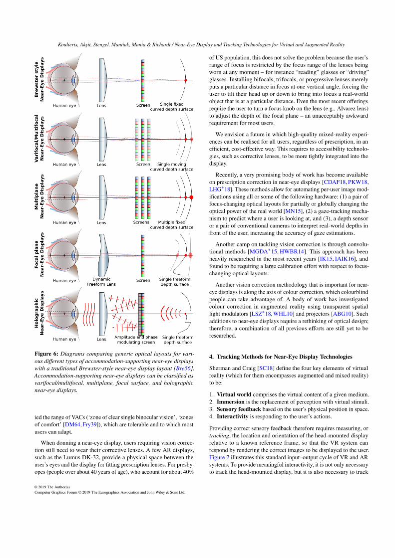
Figure 6: Diagrams comparing generic optical layouts for vari-ous different types of accommodation-supporting near-eye displayswith a traditional Brewster-style near-eye display layout [Bre56].Accommodation-supporting near-eye displays can be classified asvarifocal/multifocal, multiplane, focal surface, and holographicnear-eye displays.
ied the range of VACs (‘zone of clear single binocular vision’, ‘zonesof comfort’ [DM64, Fry39]), which are tolerable and to which mostusers can adapt.
When donning a near-eye display, users requiring vision correc-tion still need to wear their corrective lenses. A few AR displays,such as the Lumus DK-32, provide a physical space between theuser’s eyes and the display for fitting prescription lenses. For presby-opes (people over about 40 years of age), who account for about 40%
of US population, this does not solve the problem because the user’srange of focus is restricted by the focus range of the lenses beingworn at any moment – for instance “reading” glasses or “driving”glasses. Installing bifocals, trifocals, or progressive lenses merelyputs a particular distance in focus at one vertical angle, forcing theuser to tilt their head up or down to bring into focus a real-worldobject that is at a particular distance. Even the most recent offeringsrequire the user to turn a focus knob on the lens (e.g., Alvarez lens)to adjust the depth of the focal plane – an unacceptably awkwardrequirement for most users.
We envision a future in which high-quality mixed-reality experi-ences can be realised for all users, regardless of prescription, in anefficient, cost-effective way. This requires to accessibility technolo-gies, such as corrective lenses, to be more tightly integrated into thedisplay.
Recently, a very promising body of work has become availableon prescription correction in near-eye displays [CDAF18, PKW18,LHG∗18]. These methods allow for automating per-user image mod-ifications using all or some of the following hardware: (1) a pair offocus-changing optical layouts for partially or globally changing theoptical power of the real world [MN15], (2) a gaze-tracking mecha-nism to predict where a user is looking at, and (3), a depth sensoror a pair of conventional cameras to interpret real-world depths infront of the user, increasing the accuracy of gaze estimations.
Another camp on tackling vision correction is through convolu-tional methods [MGDA∗15, HWBR14]. This approach has beenheavily researched in the most recent years [IK15, IAIK16], andfound to be requiring a large calibration effort with respect to focus-changing optical layouts.
Another vision correction methodology that is important for near-eye displays is along the axis of colour correction, which colourblindpeople can take advantage of. A body of work has investigatedcolour correction in augmented reality using transparent spatiallight modulators [LSZ∗18, WHL10] and projectors [ABG10]. Suchadditions to near-eye displays require a rethinking of optical design;therefore, a combination of all previous efforts are still yet to beresearched.
4. Tracking Methods for Near-Eye Display Technologies
Sherman and Craig [SC18] define the four key elements of virtualreality (which for them encompasses augmented and mixed reality)to be:
1. Virtual world comprises the virtual content of a given medium.2. Immersion is the replacement of perception with virtual stimuli.3. Sensory feedback based on the user’s physical position in space.4. Interactivity is responding to the user’s actions.
Providing correct sensory feedback therefore requires measuring, ortracking, the location and orientation of the head-mounted displayrelative to a known reference frame, so that the VR system canrespond by rendering the correct images to be displayed to the user.Figure 7 illustrates this standard input–output cycle of VR and ARsystems. To provide meaningful interactivity, it is not only necessaryto track the head-mounted display, but it is also necessary to track
Koulieris, Aksit, Stengel, Mantiuk, Mania & Richardt / Near-Eye Display and Tracking Technologies for Virtual and Augmented Reality
The user
The system
Tracking (input)
Application
Rendering
Display (output)
Figure 7: The VR/AR system input–output cycle according to Jerald[Jer09]. The user’s motion is tracked, the application reacts to themotion and renders visual content for immediate display.
the user, their motion and their environment, so that their actionscan trigger appropriate responses.
In this section, we are therefore considering the full range oftracking techniques, from head tracking for determining the head-set’s pose, to tracking of the user’s body pose, their hands, facialexpressions and eye gaze, as well as the environment. We firstbriefly look at the underlying tracking technologies in Section 4.1and discuss their pros and cons, including their accuracy and la-tency, as well as their suitability for different tasks. See recentsurveys [BCL15, MUS16] for a more detailed account. We furtherdiscuss recent progress across different tracking modalities in Sec-tion 4.2, and how this informs the design of state-of-the-art VR andAR systems in Section 4.3.
4.1. Tracking Technologies
Convincing and immersive virtual or augmented reality requires thereal-time tracking of the user’s head-mounted display as well as theirinteraction with the world [BCL15]. Over the last few decades, manytracking approaches have been proposed, based on different trackingtechnologies as well as combinations of multiple technologies (seeexamples in Figure 8). Each approach needs to find a trade-offbetween key performance criteria [WF02], such as accuracy, updaterate, latency, jitter, noise and drift, and other considerations suchas visibility requirements, contact-based versus contact-free, andactive versus passive methods.
Figure 9: 6 degrees of freedom.
One important property oftracking approaches is howmany degrees of freedom, orDoF, they can measure. Theposition and orientation of anobject can be uniquely speci-fied using six degrees of free-dom (see figure to the right): 3DoF for translation (left–right,
up–down, forward–backward)and 3 DoF for rotation (pitch,yaw, roll), for a total of 6 DoF.Some approaches only recoverthe three rotational DoF, so that a viewer can look around a vir-tual world from a fixed viewpoint. Only 6-DoF tracking allows theviewer to move in the virtual world like in the real world.
Mechanical Tracking is one of the oldest approaches that hasbeen used at least since Ivan Sutherland’s ground-breaking head-mounted display [Sut68]. Using a mechanical arm with sensorsat the joints, position and orientation can be measured with highaccuracy and low jitter and latency. The main limitation is that themechanical arm needs to be physically connecting the object ofinterest to a fixed reference frame, such as connecting Sutherland’sdisplay to the ceiling, or a joystick to a desk. This limits the rangeof possible motions to the fixed location at which the system isinstalled. However, this may be acceptable or even desirable incertain application scenarios such as location-based entertainment.
Magnetic Tracking measures the magnetic field vector usingthree mutually orthogonal magnetometers or electromagnetic coils[RBSJ79]. Magnetometers measure static magnetic fields, such asthe Earth’s natural magnetic field, which provides a 3-DoF orien-tation measurement. Electromagnetic coils can be used to measurethe current induced by an active source, and three sources are suf-ficient for full 6-DoF pose estimation. Another main benefit ofmagnetic tracking is that no line of sight is required, which is why itis for example used by the Magic Leap One AR headset and con-troller [BLW∗17]. However, magnetic tracking tends to be sensitiveto metal as well as fairly noisy and expensive. Recently, centimetre-level accuracy has been demonstrated using only commodity WiFiinfrastructure [KK17, ZLAA∗18].
Inertial Tracking relies on accelerometers and gyroscopes to esti-mate velocity and orientation. This functionality is often groupedinto inertial measurement units (IMUs), which have become pop-ular since the introduction of microelectronic mechanical systems(MEMS) that offer a cheap and small package with a high updaterate. The biggest weakness of inertial tracking is drift, as measure-ments need to be integrated once to obtain orientation and twice toobtain position, which leads to significant drift over time. In practice,MEMS IMUs often also include magnetometers to reduce rotationaldrift, e.g., as used in the Oculus Rift development kit [LYKA14] orGoogle’s Daydream headset, which both only support 3-DoF ori-entation tracking. Many practical implementations combine IMUswith other tracking techniques (see ‘hybrid tracking’) to managedrift while benefitting from the high update rate.
Acoustic Tracking measures distances using time-of-flight orphase-coherent ultrasound waves [Sut68]. Devices are generallysmall and cheap, but suffer from low accuracy and refresh rates, andrequire line-of-sight while only providing 3-DoF orientation. Forthese reasons, acoustic tracking is becoming less common, althoughit is still being used for room-scale environments [SAP∗16].
Optical Tracking uses one or more cameras in the visual or in-frared spectrum to reconstruct the position and/or orientation of
Koulieris, Aksit, Stengel, Mantiuk, Mania & Richardt / Near-Eye Display and Tracking Technologies for Virtual and Augmented Reality
(a) (b) (c) (d) (e)
(f) (g) (h) (i)
Figure 8: Example uses of the tracking technologies discussed in Section 4.1: (a) Sutherland’s ‘Sword of Damocles’ mechanical tracker(1968) [Sut68]; (b) the Magic Leap One Controller (2018) uses magnetic tracking [BLW∗17]; (c) Google Daydream View (2017) usesinertial tracking for 3-DoF localisation of headset and controller; (d) ultrasonic tracking for room-scale 6-DoF localisation [SAP∗16]; (e)marker-based optical tracking using ARToolkit [KB99]; (f) model-based optical tracking using Vuforia; (g) SLAM-based tracking using directsparse odometry [EKC18]; (h) depth-based tracking using BundleFusion [DNZ∗17]; and (i) visual-inertial odometry [LLB∗15] as a hybridtechnique combining optical and inertial tracking.
objects relative to the camera or, alternatively, the camera’s poserelative to the environment as used in AR [BCL15, MUS16]. Ahuge range of different optical tracking approaches and technolo-gies have been proposed in recent years. They all rely on imageprocessing and computer vision to interpret the captured imagesor videos. (1) Marker-based tracking approaches look for knownartificial markers, such as retro-reflective spheres used for tradi-tional motion capture (e.g., Vicon), or 2D fiducial markers likeARToolkit [KB99] that enable 6-DoF camera pose estimation. (2) Ifthe geometry of the scene, or objects in it, is known, it can also beused for model-based tracking. A special case of this is the trackingof a planar surface, as it simplifies the pose estimation based on esti-mated homographies [MUS16]. (3) SLAM-based tracking performssimultaneous localisation and mapping in previously unknown envi-ronments. SLAM techniques have been covered thoroughly in tworecent surveys [CCC∗16, SMT18]. (4) Depth-based tracking usesdepth maps acquired from infrared-based depth sensors that have be-come widespread over the last decade. Such sensors usually operateusing the active stereo [Zha12] or time-of-flight [KBKL10] principle(e.g., Microsoft Kinect and Kinect One, respectively). Overall, mostoptical tracking approaches are usually very accurate, reasonablycheap, immune to metal and work over long ranges. However, theydo require a line of sight, some techniques require specific markers,and update rates can be low (10s of Hz).
Hybrid Tracking combines multiple tracking technologies to over-come the limitations of each one, as no single tracking technologyprovides a silver bullet [WF02]. A common combination is visual-inertial SLAM [LLB∗15], which fuses SLAM-based tracking (highaccuracy, but low update rate) with inertial tracking (high updaterate, but long-term drift) to reduce latency and increase accuracyand robustness. This is for instance used by the Microsoft HoloLensand Windows Mixed Reality HMDs [ESS∗16], as well as Apple’sARKit and Google’s ARCore AR APIs. Valve’s Lighthouse systemis another hybrid tracking technology that combines optical tracking(using a swept infrared laser) for high-accuracy positioning with in-
ertial tracking for low-latency tracking [YS16]. Hybrid systems haveshown the best overall tracking performance, but are necessarilymore complex and expensive than any single technology.
4.2. Tracking Modalities
Tracking the user and their interaction with the real and virtualworlds comes in many flavours. Now that we have looked at thearsenal of tracking technologies that are at our disposal, we willnext explore some recent advances in specific tracking modalities(see examples in Figure 10). We start with head and eye tracking,which both provide invaluable information about what imageryto show to the user. Next, we expand the tracking of the user bytracking their full body, hands and face. Finally, we are takinga quick look at current techniques for reconstructing static anddynamic environments, with which the user may be interactingwhile wearing a near-eye display.
Head Tracking In the beginning, there was only head tracking[Sut68], although Sutherland proposed both a mechanical and anultrasound-based head tracker. This early work clearly demonstratedhow important knowing the head pose is for rendering images thatappear fixed in 3D space. Great advances in tracking technologyover the last 50 years have led to widely available commercial near-eye displays that have head tracking built in, such as the Oculus Rift,which relies on IMUs [LYKA14] in combination with infrared-basedoptical tracking. Recent research prototypes have also successfullyexperimented with using a cluster of rolling-shutter cameras forkilohertz 6-DoF visual tracking [BDF16], using a single RGB-Dcamera [TTN18] or most simply a standard RGB camera [RCR18].
Eye Tracking aims to estimate the gaze direction of a user – ide-ally for both eyes, so that the 3D point at which both eyes areverging can be determined [WPDH14]. Eye trackers can be desk-mounted [WPDH14], laptop-mounted [ZSFB19], head-mounted[SB15] or using the front-facing camera of mobile phones and
Koulieris, Aksit, Stengel, Mantiuk, Mania & Richardt / Near-Eye Display and Tracking Technologies for Virtual and Augmented Reality
(a) (b) (c) (d) (e)
GazeC
apture
iTracker
(f) EgoCap mocap rig
1. Attached to bike helmet
2. Attached to Oculus VR HMD
Application scenario
Laptop
(g) (h) (i)
(j) (k) (l) (m)
(n) (o) (p) (q)
Figure 10: Examples of the tracking modalities discussed in Section 4.2: (a) head tracking with five pairs of rolling shutter cameras at kilohertzfrequencies [BDF16]; (b) image-based head tracking [RCR18]; (c) desk-mounted eye tracker below the display [WPDH14]; (d) head-mountedeye tracking [SB15]; (e) phone-based eye tracking using deep learning [KKK∗16]; (f) egocentric inside-out motion capture [RRC∗16]; (g)live motion capture from a single video camera [MSS∗17]; (h) performance capture from monocular video [XCZ∗18]; (i) egocentric handtracking from an RGBD camera [MMS∗17]; (j) tracking multiple interacting hands for VR [TTT∗17]; (k) head-mounted face tracking usingmeasure sensors [LTO∗15]; (l) face tracking from a RGBD camera [TZS∗18]; (m) performance capture of full bodies and hands [RTB17];(n) static environment reconstruction by KinectFusion [NDI∗11]; (o) annotated 3D scene reconstruction [DCS∗17]; (p) non-rigid motiontracking and surface reconstruction [GXW∗18]; and (q) real-time volumetric non-rigid reconstruction [IZN∗16].
tablets [KKK∗16, KAB18]. Near-eye input avoids the problemsof head pose and eye-region estimation, and allows use of high-resolution images of the eye. Most eye trackers work in the infraredspectrum as dark irises appear brighter in it and the corneal reflec-tion can be filtered out by an infrared bandpass filter, resulting instronger contrast to the black pupil that is used for gaze estimation.
In the following, we briefly summarise the history and state-of-the-art approaches for video-based eye tracking. We ignore otherinvasive eye tracking technologies such as scleral coil trackers.Duchowski’s book on eye tracking methodology [Duc17] providesmore practical information for the interested reader. In addition, cu-rious readers can read a detailed up-to-date survey of gaze-trackingsystems and gaze-estimation algorithms in the work of Holmqvistet al. [HNA∗11] and Kar and Corcoran [KC17].
Feature-based gaze-estimation methods locate the pupil and thenmap the pupil location to a screen location using user-specific cali-bration. The most recent pupil detection algorithms are discussedin this section. The Starburst algorithm [LWP05] iteratively locatesthe pupil center as the mean of points which exceed a differential lu-
minance threshold along the rays extending from the last best guess.In the SET method [JHB∗15], the convex hull segments of thresh-olded regions are fit to sinusoidal components. Swirski et al. [SD14]and Pupil Labs [KPB14] both start with coarse positioning usingHaar features. Swirski et al. then refine by k-means clustering theintensity histogram and a modified RANSAC ellipse fit, while PupilLabs use ellipse fitting on connected edges. ExCuSe [FKS∗15],ElSe [FSKK16], and PuRe [SFK18] use morphological edge filter-ing followed by ellipse fitting. PuRe is capable of selecting multipleedges for the final fitting and edge selection. ExCuSe and ElSeprovide alternative approaches for cases when edge detection is notapplicable. Recently, Fuhl et al. [FGS∗18] presented circular binaryfeatures (CBF) to learn conditional distributions of pupil positionsfor the datasets on which they test. These distributions are indexedby binary feature vectors and looked up at inference time.
Due to the success of deep learning methods in many areasof computer vision, the state-of-the-art algorithms are mostlybased on convolutional neural networks (CNNs) [SMS14, WBZ∗15,GWW∗16, HKN∗16, KKK∗16, WBM∗16, MBW∗17, PZBH18,
Koulieris, Aksit, Stengel, Mantiuk, Mania & Richardt / Near-Eye Display and Tracking Technologies for Virtual and Augmented Reality
PSH18,KSM∗19]. Networks with more layers generally outperformshallower ones, and VGG16 [SZ15] is emerging as a consensusarchitecture to be wrapped with preprocessing or context-awarelayers [ZSFB19]. Kim et al. propose a network architecture for low-latency and robust gaze estimation and pupil localization [KSM∗19].PupilScreen measures the pupil diameter with a CNN from sin-gle smartphone photo of the eye [MBW∗17] Additionally, otherapproaches differing from the aforementioned ones are appearance-based methods, which directly compute the gaze location from theeye image [WBZ∗15, ZSFB15, TSSB17].
Related work on remote gaze tracking includes training acrossmultiple cameras [ZHSB18], using the screen as a glint source[HLNL17], using corneal imaging for fixation extraction and activ-ity detection [LK18], and machine learning for calibrating track-ers [SFK17]. Tonsen et al. [TSSB17] explore gaze tracking usingcombinations of multiple low-resolution and low-power miniaturecameras, which is a favourable condition for mobile hardware.
Full-Body Tracking estimates human body pose in terms of akinematic skeleton, which comprises rigid bones that are connectedat joints with varying degrees of freedom [MHKS11]. Most com-mercial motion-capture systems use optical tracking with multiplecameras, either using markers (e.g., Vicon, OptiTrack) or markerless(e.g., The Captury, iPi Soft), while some systems use IMUs (e.g.,Xsens, Neuron), which are not constrained to a fixed capture volume.Motion capture has also been demonstrated using a single consumerdepth camera, such as the Microsoft Kinect [WZC12, SGF∗13],which has the benefit of being largely invariant to the colour ofclothing being worn. Approaches that use body-mounted camerasovercome the restricted capture volumes of previous approaches[SPS∗11] and also enable motion capture in space-constrained en-vironments [RRC∗16] that were previously infeasible for opticaltracking approaches. Most recently, deep learning applied to largedatasets has enabled monocular motion capture from a single cam-era [ZZP∗18], even live and in real time [MSS∗17, XCZ∗19]. Incontrast to motion capture, performance capture aims to reconstructthe surface geometry of humans, not just their skeletons [TdAS∗10];this surface reconstruction is more desirable for virtual reality ap-plications, as this would enable one to see their own body in thevirtual world. Recent monocular approaches have shown convinc-ing results with a depth sensor [DDF∗17] or just a standard videocamera [XCZ∗18].
Hand Tracking aims to reconstruct the pose of hands and fin-gers, which are crucial for our everyday interaction with the realworld. Hand tracking is a challenging problem because fingerslook very similar and tend to occlude each other. Most hand-tracking approaches use optical tracking, as it works from a dis-tance with line-of-sight. The wrist-worn Digits sensor uses a custominfrared projector-camera system [KHI∗12], but most approachesuse commodity hardware instead, particularly consumer depth cam-eras. The colour channel is sometimes used for hand segmenta-tion [OKA11], but many approaches only use the depth chan-nel [SMOT15, TBC∗16, TPT16], as it is invariant to skin colourand illumination, which makes colour-only hand tracking morechallenging [MBS∗18]. Egocentric approaches use body-mountedRGB-D cameras instead [RKS∗14, MMS∗17] to recover hand pose
from the user’s viewpoint. While most work focuses on track-ing a single hand, a few approaches specialise in tracking multi-ple interacting hands [TTT∗17, TBS∗16] or interaction with ob-jects [SMZ∗16, TA18].
Face Tracking is important for social applications such as videoconferencing and telepresence. Two recent surveys provide anup-to-date overview and evaluation of techniques for face recon-struction, tracking and applications [CAS∗18, ZTG∗18]. However,head-mounted near-eye displays create new challenges for facetracking because they occlude a large part of the face. Occlusion-aware techniques [HMYL15] partially address this problem, whileother approaches integrate pressure sensors into the edge of thehead-mounted display to directly measure the deformation of theface [LTO∗15]. When combined with in-headset eye tracking, thereconstructed facial models become more expressive, which en-ables high-fidelity facial and speech animation [OLSL16] as well asgaze-aware facial reenactment [TZS∗18].
Multimodal Tracking is an emerging area, which simultaneouslytracks multiple modalities to obtain a more comprehensive recon-struction of the user. Such approaches for example combine trackingof bodies and hands [RTB17] or bodies, hands and faces [JSS18].
Environment Reconstruction is required to understand how auser interacts with the real world, and hence also the virtual world.Recent surveys provide an excellent introduction to and overviewof 3D reconstruction using RGB-D cameras [ZSG∗18], as well assimultaneous localisation and mapping (SLAM) in static [CCC∗16]and dynamic environments [SMT18]. Most 3D reconstruction ap-proaches assume static environments and integrate multiple depthmaps from a moving camera using a truncated signed distancefunction, e.g. the pioneering KinectFusion approach [NDI∗11].Subsequent work expanded the supported capture volume usingvoxel hashing [NZIS13], added support for colour video cameras[PRI∗13], achieved high performance on mobile devices [KPR∗15],and integrated loop-closure optimisation with surface re-integration[DNZ∗17]. More recent work goes beyond reconstructing just ge-ometry and also estimates part labels to help understand real-worldenvironments [ZXTZ15, DCS∗17]. Most environments, however,are not entirely static and require non-rigid reconstruction and mo-tion tracking [ZNI∗14, NFS15], deformation of integration vol-umes [IZN∗16], dense visual SLAM [WSMG∗16] or L0 motionregularisation [GXW∗18].
4.3. Tracking Applications
In this section, we review a select set of tracking applications inVR/AR: gaze tracking to speed up rendering while maintainingvisual fidelity, and gesture/gaze tracking to control user interfaces.
Gaze-Aware Displays Being able to detect and to adapt to thegaze direction facilitates many new ways to enhance digital displays.The notion of gaze-contingent or gaze-aware display devices datesback at least two decades. In the following, some of the most recentkey contributions of the field are presented. Excellent review articleson gaze-contingent techniques and applications include those ofReingold [RLMS03], O’Sullivan [OHM∗04], Duchowski [DCM04,
Koulieris, Aksit, Stengel, Mantiuk, Mania & Richardt / Near-Eye Display and Tracking Technologies for Virtual and Augmented Reality
DÇ07], Dietrich [DGY07], Bartz et al. [BCFW08], Masia et al.[MWDG13] and Stengel et al. [SM16].
Another application for eye tracking in HMDs is foveated ren-dering [GFD∗12, SGEM16, PSK∗16, WRK∗16], which we brieflytouched on in Section 3.3. The rapid fall-off in acuity from ourfoveal to our peripheral field of vision is exploited to allocate ren-dering and video processing resources more efficiently. Stengelet al. present a perception model for adaptive image-space sam-pling [SGEM16]. In this work, the scene is rendered and displayedin full detail only within a small circle around the gaze direction,and the rendered image resolution decreases continuously with in-creasing angular distance from the foveal field of vision. Weieret al. present a perception-based foveation scheme using ray trac-ing [WRK∗16, WRHS18]. In recent work, Mauderer et al. createda model for simultaneous contrast perception [MFN16]. The ap-proach modulates the colour of the scene in the periphery accordingto the gaze direction, which results in more saturated colour per-ception. The authors plan to use the effect to create a new formof high dynamic range images with increased perceivable gamutsize [MFN16]. Patney et al. show that the level of foveation can beincreased if the local contrast is boosted and therefore perceptuallymaintained [PSK∗16]. In follow-up work, Sun et al. have presentedfoveation for light-field displays [SHK∗17]. Lungaro et al. present afast foveation scheme for reducing bandwidth requirements duringvideo transmission [LSV∗18].
Dedicated measurements to determine acceptable latency forgaze-contingent displays have been conducted in several studies[EMAH04, LW07, RJG∗14, APLK17]. The measured end-to-end la-tency comprises the full gaze capture, rendering and display pipeline,starting with capturing the frame for eye-tracking and ending withthe reception of the photons emitted by the display by the photore-ceptors in the retina. Loschky et al. observed that the display hasto be refreshed after 5 ms to 60 ms following a saccade for an im-age update to go undetected. The acceptable delay depends on thetask of the application and the stimulus size in terms of inducedperipheral degradation. Beyond that time delay, detection likeli-hood rises quickly [LW07]. It is therefore important to decide ifthe intended task is concerned with perceptual fidelity or visualperformance. Albert et al. present latency requirements for a varietyof VR scenarios [APLK17].
Under normal circumstances, attention is guided by visual fea-tures and the task of the user, which is exploited for passive gazeprediction [KDCM14]. Strategies for gaze guidance are aiming forsteering attention to a specified target location, which can signif-icantly differ from the natural fixation location. Therefore, gazeguidance requires altering the visible scene content. McNamaraand Bailey introduced a more subtle, yet effective gaze guidancestrategy [MBS∗12, BMSG09]. The authors apply image-space mod-ulations in the luminance channel to guide a viewer’s gaze througha scene without interrupting their visual experience. The principlehas been successfully applied to increase search task performanceas well as to direct gaze in narrative art [MBS∗12]. Hence, thetechnique may support understanding of a painting in a gallery ora related use case, but may also be useful for gaze guidance insimulators and training, pervasive advertising or perceptually adap-tive rendering [BMSG09]. Grogorick et al. explored subtle gaze
direction for wide field of view scenarios in immersive environ-ments [GSEM17]. Recently, Sun et al. successfully apply subtlegaze guidance for redirected walking in VR [SPW∗18]. Along simi-lar lines, Langbehn et al. exploit blink-induced suppression for thesame redirected walking task [LSL∗18].
Gesture-Driven User Interfaces 3D gestural interaction providesan intuitive and natural way of 3D interaction, often providinga detailed representation of hands and fingers visualised in a 3Dspatial context, while using a near-eye display [LaV13, KPL17].Accurately recognising detailed 3D gestures, especially involvingsubtle finger movement is paramount, so that interaction appearsseamless. One of the key devices for hands/finger recognition, whichprovides low-latency, immediate interaction with 3D space is theLeap Motion device. Because of its low cost, it became availableto a wide range of users of entertainment as well as XR trainingapplications [Car16, NLB14]. The Leap Motion is a small deviceconnected via USB, which is often mounted onto a near-eye display.Using two monochromatic infrared (IR) cameras and three IR LEDs,the device recognises gestures within approximately 1 metre. TheLEDs generate pattern-less IR light and the cameras capture ataround 200 Hz, synthesising 3D position data for fast hand tracking.The smaller range of recognition and higher resolution of the devicedifferentiates Leap Motion from the Kinect, which is more suitablefor full-body tracking in a space the size of a room [GB18,TSSL15].Although advances in gestural recognition hardware are rapid and3D gesture interfaces are now widely adopted, the technologies arenot yet stable, especially in relation to full-body motion capture sothat the ecological validity of immersive experiences is guaranteed[VPK17].
Gaze-Driven User Interfaces Gaze-based interaction is intu-itive and natural as tasks can be performed directly in the spa-tial context without having to search for an out-of-view keyboardor mouse [Duc18]. Past research as early as the 1980s investi-gated eye-tracking-based interfaces to interact with 2D user inter-faces [HWM∗89], as well as gaze input for people with disabili-ties [YF87]. Using gaze as an interaction metaphor for attentiveuser interfaces is intuitive for search tasks, but also turns out tobe ambiguous and error-prone when being used for selecting ortriggering commands [Jac91]. Special graphical user interfaces re-duce ambiguities for gaze writing tasks, but have not been able toreach interaction bandwidths that are competitive to established in-put devices such as the keyboard [WRSD08, PT08, MHL13]. Undernormal conditions, the eye is used to gain information about the en-vironment, but not to trigger commands. However, different studieshave shown the gain in task performance if gaze is combined withother modalities, such as touch or head gestures [SD12, MHP12].Recently, gaze-based interaction has been employed for Locked-InSyndrome (LIS) patients combining eye movement and electroen-cephalogram (EEG) signals confirming or cancelling gaze-basedactions [HLZ∗16].
A common issue when using an eye-tracked interface as an inputdevice is known as the ‘Midas touch’ problem. Eye movements areinvoluntary and accidental interface activation is frequent. Fixationtime could last from 450 ms to 1 second when a gaze-based inter-face is initially used, but has been shown to become faster with
Koulieris, Aksit, Stengel, Mantiuk, Mania & Richardt / Near-Eye Display and Tracking Technologies for Virtual and Augmented Reality
experience to around 300 ms in the case of gaze typing [MAŠ09].Faster fixation times, however, when requested as part of a formalexperimental design are stressful to the users. Speech recognitionhas been used in the past to signify an event as a solution to theMidas touch issue, requiring accurate synchronisation of gaze andspeech data streams in order to be reliable [KTH∗03].
Eye tracking has been utilised for interaction in near-eye dis-plays, showing performance improvements compared to finger point-ing [TJ00]. Recently, various companies incorporate eye trackingin novel near-eye displays, such as the FOVE and Magic Leap,or providing add-ons for near-eye displays such as for the OculusRift and HoloLens [vdMKS17]. Eye-tracked interfaces for immer-sive viewing, covering commonly operated actions of everydaycomputing such as mail composing and multimedia viewing, havedemonstrated less typing errors while operating the eye-controlledinterface compared to using the standard keyboard, while invok-ing stronger enjoyment and satisfaction associated with the eye-tracked 3D interface [SKM15]. The Midas touch issue in gaze-driven near-eye displays is dealt with by employing an additionalmechanical input (switch) to signify a selection in the immersiveenvironment [SKM15], or a method in which users perform a distinc-tive two-step gaze gesture for object selection [MGFY18]. Recentresearch explored natural gaze-based interaction techniques in im-mersive environments, such as eye-gaze selection based on eye gazeand inertial reticles, cluttered object selection that takes advantageof smooth pursuit, and head-gesture-based interaction relying on thevestibulo-ocular reflex [PLLB17]. Gaze-based interaction is shownto improve user experience and can demonstrate, in some cases,comparable performance to standard interaction techniques.
5. Future Work
In this section, we discuss the variety of open problems and researchchallenges that remain unsolved.
The Vergence–Accommodation Conflict is one of the most sig-nificant ergonomic issues related to viewer fatigue. The conflictis common for most young users of modern consumer-grade im-mersive near-eye displays, when viewing stereoscopic 3D con-tent [KBBD17]. The conflict is caused because the plane of focus(i.e., the screen) is fixed, whereas eye vergence movements occurcontinuously when fusing stereoscopic content [HGAB08]. For ex-ample, in a VR gaming scenario, when the player is in control ofthe view, fast-moving collisions with buildings or objects will resultin excessive disparities which, for the vast majority of users, causevisual strain and jeopardise the quality of the overall gaming experi-ence. Symptoms range from slight discomfort that can cause majoreye strain to visually-induced dizziness, and lead to significantlyreduced depth perception. The level of discomfort increases withthe exposure time to 3D content which is not calibrated for comfort-able viewing. High disparities force the eyes to rotate unnaturally inrelation to each other.
Software-based solutions to the vergence–accommodation con-flict include the stereo-grading process, i.e., altering the depth struc-ture of a scene by drawing objects in a user’s comfortable disparityrange, also known as the comfort zone of the observer, have demon-strated enhanced viewing comfort [KDCM16, KDM∗16]. Recent
stereo grading advances for 3D games improve perceived qualitybased on the available gaze information, applying localised disparitymanagement, for objects predicted to be attended or on areas basedon the current task [KDCM16]. Such approaches smoothly relocatethe perceived depth of attended objects/areas into the comfort zone,maintaining a rich sense of depth. However, stereo-grading solu-tions are software-based and rather limited, suffering from local orglobal card-boarding effects, often modifying depth and speed ofobjects and are not suitable for truly real-time arbitrary disparitymanipulations [OHB∗11]. Recently, it has been shown that accom-modation can be driven quite effectively when significant opticalaberrations of the human eye are taken into account when renderingfor VR, in particular using chromatic aberration [CLS∗17]. A com-bination of optical solutions, eye tracking and rendering techniquesare now driving the development of consumer-driven near-eye dis-plays. These methods, based on the focus-adjustable-lens designthat drives accommodation effectively, truly have the potential toresolve the vergence–accommodation conflict in the near future.
Gaze Tracking is a mandatory technology for many of the pro-posed display concepts and therefore has to become an industrystandard. Along these lines, Khronos OpenXR [Khr18] has becomethe most promising attempt to establish low-latency eye tracking asan open and cross-platform standard in the virtual reality and mixedreality software ecosystem. Augmented reality glasses introduceadditional constraints in terms of power consumption and physicalsize of the tracking hardware. Reaching this goal requires moreresearch on mobile, small-scale, low-power, robust and accurateeye-tracking technology. Although attempts using multiple minia-ture cameras or photo diodes are promising [TSSB17,LLZ17], theseapproaches are not yet suitable for accurate tracking under arbi-trary lighting conditions and longer periods of time. Gaze predictionmethods [ATM∗17, KDCM15] and other specialised signal filterscan be expected to reduce latency issues or high sampling rates.
The tracking equipment shifting over time with respect to thehead also usually introduces errors in gaze estimation. Eye locationestimation from camera frames facilitates drift compensation, butusually requires high-resolution data and is therefore only viablefor VR or desktop scenarios. Eye trackers within AR devices haveto solve this problem in new ways and might require additionallow-power sensors measuring the head pose with respect to the ARdevice. With the advent of broadly used gaze tracking, we can expectnew applications enabled by the user’s gaze [SGE∗15] as well asnew usages of gaze data. Games and VR experiences will greatlybenefit from gaze information to enable enhanced user interfaces,more social interaction through eye contact [SWM∗08] and reducedcomputation efforts in rendering [PSK∗16, SGEM16]. Multimodalsaliency and attention models [EZP∗13] could greatly improve theaccuracy of user behaviour understanding and related applications,such as for foveated rendering.
In addition, user customisation and automated device calibration,user profiling and user-friendly identification will be enabled whenbiometric eye data can be acquired on the fly [FD00]. However, secu-rity and privacy of the individual user has to be maintained to preventidentity theft. Recently, eye tracking for medical rehabilitation hasbeen shown to be feasible [YWL∗17, ŽHH∗17], e.g., to cure lazyeyes by learning to see 3D in VR, and then in reality. Blink rate, pupil
Koulieris, Aksit, Stengel, Mantiuk, Mania & Richardt / Near-Eye Display and Tracking Technologies for Virtual and Augmented Reality
size and saccade measurements allow for cognitive state, behaviour,fatigue and emotion analysis in real time [AAGW14, ZS82, SS00].Each of these components constitutes a great research field by itself.What is missing is an efficient way to acquire ground-truth data forthe development of machine-learning-based methods.
User and Environment Tracking are crucial for achieving con-vincing and immersive virtual and augmented reality experiences[BCL15]. Research in these areas has made great progress in recentyears, as witnessed by the wealth of techniques and approaches sur-veyed in Section 4. However, tracking is far from a solved problem.In our opinion, the four main remaining challenges that need tobe addressed are robustness, speed, efficiency and availability. (1)Robustness is needed for real-world applications that go beyond theproof-of-concept stage demonstrated by current research prototypes.(2) Speed is a necessity, as the user and their environment need tobe tracked in real time with minimal latency and high update rate toavoid disorientation and discomfort. (3) Efficiency is required whentracking needs to be performed within the limited resources of stand-alone devices, including limited computation, memory and powerbudgets. (4) Availability of state-of-the-art tracking implementationsis currently limited as most are proprietary; freely available andgenerously licensed open-source implementations will facilitate thedevelopment of a larger range of future display devices, as it lowersthe barrier of entry into the market. It is worth noting that not allareas of tracking face all of these challenges. Head tracking, forexample, is arguably solved sufficiently robustly, quickly and effi-ciently in state-of-the-art consumer-level VR and AR head-mounteddisplays, but these implementations are proprietary and, to the bestof our knowledge, there are no comparable free solutions.
6. Conclusion
In this state-of-the-art report, we summarised the established andrecent work in the area of near-eye displays and tracking technolo-gies. We first covered relevant background such as optics and humanvisual perception, and then described the most fundamental but alsothe most recent advances in immersive near-eye display and trackingtechnologies. However, despite decades of research and progress,a variety of open problems and research challenges delineated inthe previous section, such as the vergence–accommodation conflictand user and environment tracking, remain unsolved. One of theleading drivers of future headset innovations will be advancementsin optics technology. Significant progress in focus-adjustable lensassemblies is expected to provide a much more comfortable HMDexperience. In future headset designs, it may also be necessary tomeasure accommodation in situ. Pivotal improvements in wavefrontaccommodation sensing, such as the Hartmann–Shack sensor, willallow the development of practical systems for widespread use.
We hope that our discussion of these challenges will inspireresearch on future directions needing further investigation. We lookforward to these advances.
Acknowledgements C.R. acknowledges funding from RCUKgrant CAMERA (EP/M023281/1) and an EPSRC-UKRI InnovationFellowship (EP/S001050/1). R.K.M acknowledges funding fromthe European Research Council (ERC) under the European Union’s
Horizon 2020 research and innovation programme (grant agreementn◦ 725253–EyeCode).
Appendix A: Acronyms
AMOLED Active-Matrix Organic Light-Emitting DiodeAR Augmented RealityBFI Black Frame InsertionCBF Circular Binary FeaturesCPD Cycles Per DegreeCSF Contrast Sensitivity FunctionDoF Degree of FreedomEEG ElectroencephalogramFoV Field of ViewHDR High Dynamic RangeHMD Head-Mounted DisplayHOE Holographic Optical ElementHVS Human Visual SystemIMU Inertial Measurement UnitIPD Interpupillary DistanceIPS In-Plane SwitchingIR InfraredLCD Liquid Crystal DisplayLCoS Liquid Crystal on SiliconLED Light Emitting DiodeLIS Locked-In SyndromeMAR Minimum Angle of ResolutionMEMS Micro-Electro-Mechanical SystemsMVA Multidomain Vertical AlignmentNED Near-Eye DisplayNELD Near-Eye Light-field DisplayOLED Organic Light Emitting DiodeSLAM Simultaneous Localisation And MappingSLM Spatial Light ModulatorSPEM Smooth Pursuit Eye MotionTN Twisted NematicVAC Vergence-Accommodation ConflictVR Virtual RealityXR Cross/Extended Reality
Koulieris, Aksit, Stengel, Mantiuk, Mania & Richardt / Near-Eye Display and Tracking Technologies for Virtual and Augmented Reality
References[AAGW14] ALGHOWINEM S., ALSHEHRI M., GOECKE R., WAGNER
M.: Exploring eye activity as an indication of emotional states using aneye-tracking sensor. In Intelligent Systems for Science and Information,Chen L., Kapoor S., Bhatia R., (Eds.). Springer, 2014, pp. 261–276. 18
[ABG10] AMANO T., BIMBER O., GRUNDHÖFER A.: Appearance En-hancement for Visually Impaired with Projector Camera Feedback. Tech.rep., Bauhaus University Weimar, 2010. 11
[ACR∗19] AKSIT K., CHAKRAVARTHULA P., RATHINAVEL K., JEONGY., ALBERT R., FUCHS H., LUEBKE D.: Manufacturing application-driven foveated near-eye displays. IEEE Trans. Vis. Comput. Graph.(2019). 10
[Ade82] ADELSON E. H.: Saturation and adaptation in the rod system.Vision Research 22, 10 (1982), 1299–1312. 4
[AKGD17] ALVAREZ T. L., KIM E. H., GRANGER-DONETTI B.: Adap-tation to progressive additive lenses: Potential factors to consider. Scien-tific Reports 7, 1 (2017), 2529. 10
[ALK∗17a] AKSIT K., LOPES W., KIM J., SHIRLEY P., LUEBKE D.:Near-eye varifocal augmented reality display using see-through screens.ACM Trans. Graph. 36, 6 (2017), 189:1–13. 9, 10
[ALK∗17b] AKSIT K., LOPES W., KIM J., SPJUT J., PATNEY A.,SHIRLEY P., LUEBKE D., CHOLEWIAK S. A., SRINIVASAN P., NG R.,BANKS M. S., LOVE G. D.: Varifocal virtuality: A novel optical lay-out for near-eye display. In SIGGRAPH Emerging Technologies (2017),pp. 25:1–2. 10
[APLK17] ALBERT R., PATNEY A., LUEBKE D., KIM J.: Latency re-quirements for foveated rendering in virtual reality. ACM Trans. Appl.Percept. 14, 4 (2017), 25. 16
[ARS∗18] ALEXANDER J., ROUDAUT A., STEIMLE J., HORNBAEK K.,BRUNS ALONSO M., FOLLMER S., MERRITT T.: Grand challenges inshape-changing interface research. In CHI (2018). 7
[ATM∗17] ARABADZHIYSKA E., TURSUN O. T., MYSZKOWSKI K.,SEIDEL H.-P., DIDYK P.: Saccade landing position prediction for gaze-contingent rendering. ACM Trans. Graph. 36, 4 (2017), 50:1–12. 17
[AWGB04] AKELEY K., WATT S. J., GIRSHICK A. R., BANKS M. S.:A stereo display prototype with multiple focal distances. ACM Trans.Graph. 23, 3 (2004), 804–813. 9
[Bak49] BAKER H. D.: The course of foveal light adaptation measured bythe threshold intensity increment. J. Opt. Soc. Am. 39, 2 (1949), 172–179.4
[Bal81] BALDWIN D.: Area of interest: Instantaneous field of view visionmodel. In Image Generation/Display Conference (1981), pp. 481–496.10
[Bar04] BARTEN P. G. J.: Formula for the contrast sensitivity of thehuman eye. In Image Quality and System Performance (2004), pp. 231–238. 3
[BCFW08] BARTZ D., CUNNINGHAM D., FISCHER J., WALLRAVENC.: The role of perception for computer graphics. In EurographicsState-of-the-Art Reports (2008), pp. 65–86. 16
[BCL15] BILLINGHURST M., CLARK A., LEE G.: A survey of aug-mented reality. Foundations and Trends in Human–Computer Interaction8, 2–3 (2015), 73–272. 12, 13, 18
[BDF16] BAPAT A., DUNN E., FRAHM J. M.: Towards kilo-Hertz 6-DoFvisual tracking using an egocentric cluster of rolling shutter cameras.IEEE Trans. Vis. Comput. Graph. 22, 11 (2016), 2358–2367. 13, 14
[BKLP04] BOWMAN D., KRUIJFF E., LAVIOLA JR. J. J., POUPYREVI. P.: 3D User interfaces: theory and practice, CourseSmart eTextbook.Addison-Wesley, 2004. 7
[BKV11] BOLTON J., KIM K., VERTEGAAL R.: SnowGlobe: A sphericalfish-tank VR display. In CHI Extended Abstracts (2011), pp. 1159–1164.7
[BLW∗17] BUCKNOR B., LOPEZ C., WOODS M. J., ALY A. H. M.,PALMER J. W., RYNK E. F.: Electromagnetic tracking with augmentedreality systems. US Patent Application US20170307891A1, 2017. 12, 13
[BMSG09] BAILEY R., MCNAMARA A., SUDARSANAM N., GRIMMC.: Subtle gaze direction. ACM Trans. Graph. 28, 4 (2009), 100:1–14.16
[BPH13] BROCKMEYER E., POUPYREV I., HUDSON S.: PAPILLON:designing curved display surfaces with printed optics. In UIST (2013),pp. 457–462. 7
[Bre56] BREWSTER D.: The Stereoscope: Its History, Theory, and Con-struction. John Murray, 1856. 8, 11
[Bro99] BROOKS JR F. P.: What’s real about virtual reality? IEEE Comput.Graph. Appl. 19, 6 (1999), 16–27. 1
[BSA91] BANKS M. S., SEKULER A. B., ANDERSON S. J.: Peripheralspatial vision: Limits imposed by optics, photoreceptors, and receptorpooling. J. Opt. Soc. Am. 8, 11 (1991), 1775–1787. 3
[BW10] BENKO H., WILSON A. D.: Multi-point interactions with immer-sive omnidirectional visualizations in a dome. In International Conferenceon Interactive Tabletops and Surfaces (ITS) (2010), pp. 19–28. 7
[BWB08] BENKO H., WILSON A. D., BALAKRISHNAN R.: Sphere:Multi-touch interactions on a spherical display. In UIST (2008), pp. 77–86. 7
[Car16] CARDOSO J. C. S.: Comparison of gesture, gamepad, and gaze-based locomotion for VR worlds. In VRST (2016), pp. 319–320. 16
[CAS∗18] CHRYSOS G. G., ANTONAKOS E., SNAPE P., ASTHANA A.,ZAFEIRIOU S.: A comprehensive performance evaluation of deformableface tracking “in-the-wild”. Int. J. Comput. Vision 126, 2 (2018), 198–232.15
[CCC∗16] CADENA C., CARLONE L., CARRILLO H., LATIF Y., SCARA-MUZZA D., NEIRA J., REID I., LEONARD J. J.: Past, present, and futureof simultaneous localization and mapping: Toward the robust-perceptionage. IEEE Transactions on Robotics 32, 6 (2016), 1309–1332. 13, 15
[CDAF18] CHAKRAVARTHULA P., DUNN D., AKSIT K., FUCHS H.:FocusAR: Auto-focus augmented reality eyeglasses for both real worldand virtual imagery. IEEE Trans. Vis. Comput. Graph. 24, 11 (2018),2906–2916. 11
[CKS18] CHANG J.-H. R., KUMAR B. V. K. V., SANKARANARAYANANA. C.: Towards multifocal displays with dense focal stacks. ACM Trans.Graph. 37, 6 (2018), 198:1–17. 9
[CLS∗17] CHOLEWIAK S. A., LOVE G. S., SRINIVASAN P. P., NGR., BANKS M. S.: ChromaBlur: Rendering chromatic eye aberrationimproves accommodation and realism. ACM Trans. Graph. 36, 6 (2017),210:1–12. 17
[CLvdHE16] CUPERUS A. A., LAKEN M., VAN DEN HOUT M. A.,ENGELHARD I. M.: Degrading emotional memories induced by a virtualreality paradigm. J. Behav. Ther. Exp. Psychiatry 52 (2016), 45–50. 8
[CSKH90] CURCIO C. A., SLOAN K. R., KALINA R. E., HENDRICK-SON A. E.: Human photoreceptor topography. J. Comp. Neurol. 292, 4(1990), 497–523. 2, 3
[CV95] CUTTING J. E., VISHTON P. M.: Perceiving layout and knowingdistances: The integration, relative potency, and contextual use of differentinformation about depth. In Perception of Space and Motion, Epstein W.,Rogers S., (Eds.). Academic Press, 1995, pp. 69–117. 2
[CWHT09] CHENG D., WANG Y., HUA H., TALHA M.: Design of anoptical see-through head-mounted display with a low f-number and largefield of view using a freeform prism. Applied Optics 48, 14 (2009),2655–2668. 9
[DÇ07] DUCHOWSKI A. T., ÇÖLTEKIN A.: Foveated gaze-contingentdisplays for peripheral LOD management, 3D visualization, and stereoimaging. ACM Trans. Multimed. Comput. Commun. Appl. 3, 4 (2007),6:1–18. 15
Koulieris, Aksit, Stengel, Mantiuk, Mania & Richardt / Near-Eye Display and Tracking Technologies for Virtual and Augmented Reality
[DCM04] DUCHOWSKI A. T., COURNIA N., MURPHY H.: Gaze-contingent displays: A review. CyberPsychology & Behavior 7, 6 (2004),621–634. 15
[DCS∗17] DAI A., CHANG A. X., SAVVA M., HALBER M.,FUNKHOUSER T., NIESSNER M.: ScanNet: Richly-annotated 3D re-constructions of indoor scenes. In CVPR (2017), pp. 5828–5839. 14,15
[DDF∗17] DOU M., DAVIDSON P., FANELLO S. R., KHAMIS S., KOW-DLE A., RHEMANN C., TANKOVICH V., IZADI S.: Motion2Fusion:Real-time volumetric performance capture. ACM Trans. Graph. 36, 6(2017), 246:1–16. 15
[DF04] D’ANDRADE B. W., FORREST S. R.: White organic light-emitting devices for solid-state lighting. Advanced Materials 16, 18(2004), 1585–1595. 5
[DGY07] DIETRICH A., GOBBETTI E., YOON S.-E.: Massive-modelrendering techniques: A tutorial. IEEE Comput. Graph. Appl. 27, 6(2007), 20–34. 16
[DH02] DIFEDE J., HOFFMAN H. G.: Virtual reality exposure therapyfor World Trade Center post-traumatic stress disorder: A case report.CyberPsychology & Behavior 5, 6 (2002), 529–535. 7
[DM64] DONDERS F. C., MOORE W. D.: On the anomalies of accommo-dation and refraction of the eye: With a preliminary essay on physiologicaldioptrics, vol. 22. New Sydenham Society, 1864. 11
[DNZ∗17] DAI A., NIESSNER M., ZOLLHÖFER M., IZADI S.,THEOBALT C.: BundleFusion: Real-time globally consistent 3D re-construction using on-the-fly surface reintegration. ACM Trans. Graph.36, 3 (2017), 24:1–18. 13, 15
[DR90] DROESSLER J. G., ROTIER D. J.: Tilted cat helmet-mounteddisplay. Optical Engineering 29, 8 (1990). 9
[DTT∗17] DUNN D., TIPPETS C., TORELL K., KELLNHOFER P., AKSITK., DIDYK P., MYSZKOWSKI K., LUEBKE D., FUCHS H.: Wide field ofview varifocal near-eye display using see-through deformable membranemirrors. IEEE Trans. Vis. Comput. Graph. 23, 4 (2017), 1322–1331. 9,10
[Duc17] DUCHOWSKI A. T.: Eye Tracking Methodology, 3rd ed. Springer,2017. 14
[Duc18] DUCHOWSKI A. T.: Gaze-based interaction: A 30 year retrospec-tive. Computers & Graphics 73 (2018), 59–69. 16
[DXCZ15] DALY S., XU N., CRENSHAW J., ZUNJARRAO V. J.: Apsychophysical study exploring judder using fundamental signals andcomplex imagery. SMPTE Motion Imaging Journal 124, 7 (2015), 62–70.6
[EKC18] ENGEL J., KOLTUN V., CREMERS D.: Direct sparse odometry.IEEE Trans. Pattern Anal. Mach. Intell. 40, 3 (2018), 611–625. 13
[Ell94] ELLIS S. R.: What are virtual environments? IEEE Comput.Graph. Appl. 14, 1 (1994), 17–22. 1
[EMAH04] ELLIS S. R., MANIA K., ADELSTEIN B. D., HILL M. I.:Generalizeability of latency detection in a variety of virtual environments.Proceedings of the Human Factors and Ergonomics Society Annual Meet-ing 48, 23 (2004), 2632–2636. 16
[ESS∗16] EBSTYNE M. J., SCHAFFALITZKY F., STEEDLY D., CHAN C.,EADE E., KIPMAN A., KLEIN G.: Pose tracking an augmented realitydevice. US Patent 9495801B2, 2016. 13
[EZP∗13] EVANGELOPOULOS G., ZLATINTSI A., POTAMIANOS A.,MARAGOS P., RAPANTZIKOS K., SKOUMAS G., AVRITHIS Y.: Mul-timodal saliency and fusion for movie summarization based on aural,visual, and textual attention. IEEE Transactions on Multimedia 15, 7(2013), 1553–1568. 17
[FD00] FRISCHHOLZ R. W., DIECKMANN U.: Biold: a multimodalbiometric identification system. Computer 33, 2 (2000), 64–68. 17
[Fen06] FENG X.-F.: LCD motion-blur analysis, perception, and reductionusing synchronized backlight flashing. In Human Vision and ElectronicImaging (2006). 7
[FGS∗18] FUHL W., GEISLER D., SANTINI T., APPEL T., ROSENSTIELW., KASNECI E.: CBF: Circular binary features for robust and real-timepupil center detection. In ETRA (2018), pp. 8:1–6. 14
[FKS∗15] FUHL W., KÜBLER T., SIPPEL K., ROSENSTIEL W., KAS-NECI E.: ExCuSe: Robust pupil detection in real-world scenarios. InInternational Conference on Computer Analysis of Images and Patterns(2015), pp. 39–51. 14
[FR84] FISCHER B., RAMSPERGER E.: Human express saccades: ex-tremely short reaction times of goal directed eye movements. Experimen-tal Brain Research 57, 1 (1984), 191–195. 4
[Fry39] FRY G. A.: Further experiments on the accommodation-convergence relationship. Optometry and Vision Science 16, 9 (1939),325–336. 11
[FSKK16] FUHL W., SANTINI T. C., KÜBLER T., KASNECI E.: ElSe:Ellipse selection for robust pupil detection in real-world environments. InETRA (2016), pp. 123–130. 14
[GB18] GONÇALVES A., BERMÚDEZ S.: KAVE: Building Kinect basedCAVE automatic virtual environments, methods for surround-screen pro-jection management, motion parallax and full-body interaction support.Proc. ACM Hum.-Comput. Interact. 2, EICS (2018), 10. 16
[GFD∗12] GUENTER B., FINCH M., DRUCKER S., TAN D., SNYDER J.:Foveated 3D graphics. ACM Trans. Graph. 31, 6 (2012), 164:1–10. 16
[GHM∗06] GELINCK G. H., HUITEMA H. E. A., MIL M., VEENEN-DAAL E., LIESHOUT P. J. G., TOUWSLAGER F., PATRY S. F., SOHN S.,WHITESIDES T., MCCREARY M. D.: A rollable, organic electrophoreticqvga display with field-shielded pixel architecture. Journal of the Societyfor Information Display 14, 2 (2006), 113–118. 7
[Gil91] GILBOA P.: Designing the right visor. In Large Screen Projection,Avionic, and Helmet-Mounted Displays (1991). 9
[GMB06] GODIN G., MASSICOTTE P., BORGEAT L.: High-resolutioninsets in projector-based stereoscopic displays: principles and techniques.In Stereoscopic Displays and Virtual Reality Systems (2006). 10
[Gol10a] GOLDSTEIN E. B.: Encyclopedia of perception. SAGE Publica-tions, Inc, 2010. 2, 4
[Gol10b] GOLDSTEIN E. B.: Sensation and Perception, 8th ed.Wadsworth-Thomson Learning, Pacific Grove, 2010. 2, 3
[Goo17] GOODMAN J. W.: Introduction to Fourier optics, 4th ed. W. H.Freeman, 2017. 5
[GSEM17] GROGORICK S., STENGEL M., EISEMANN E., MAGNOR M.:Subtle gaze guidance for immersive environments. In Symposium onApplied Perception (2017), pp. 4:1–7. 16
[GWW∗16] GOU C., WU Y., WANG K., WANG F.-Y., JI Q.: Learning-by-synthesis for accurate eye detection. In ICPR (2016), pp. 3362–3367.14
[GXW∗18] GUO K., XU F., WANG Y., LIU Y., DAI Q.: Robust non-rigidmotion tracking and surface reconstruction using L0 regularization. IEEETrans. Vis. Comput. Graph. 24, 5 (2018). 14, 15
[HB16] HAINICH R. R., BIMBER O.: Displays: Fundamentals & Appli-cations, 2nd ed. A K Peters/CRC Press, 2016. 5, 6
[HCOB10] HELD R. T., COOPER E. A., O’BRIEN J. F., BANKS M. S.:Using blur to affect perceived distance and size. ACM Trans. Graph. 29,2 (2010), 19:1–16. 2
[HCW15] HUANG F.-C., CHEN K., WETZSTEIN G.: The light fieldstereoscope: Immersive computer graphics via factored near-eye lightfield displays with focus cues. ACM Trans. Graph. 34, 4 (2015), 60:1–12.9
[HFU13] HEDILI M. K., FREEMAN M. O., UREY H.: Microlens array-based high-gain screen design for direct projection head-up displays.Applied Optics 52, 6 (2013), 1351–1357. 7
[HGAB08] HOFFMAN D. M., GIRSHICK A. R., AKELEY K., BANKSM. S.: Vergence–accommodation conflicts hinder visual performanceand cause visual fatigue. Journal of Vision 8, 3 (2008), 33. 8, 17
Koulieris, Aksit, Stengel, Mantiuk, Mania & Richardt / Near-Eye Display and Tracking Technologies for Virtual and Augmented Reality
[HH91] HORTON J., HOYT W.: The representation of the visual field inhuman striate cortex. a revision of the classic Holmes map. Archives ofOphthalmology 109, 6 (1991), 816–824. 4
[HJ14] HUA H., JAVIDI B.: A 3D integral imaging optical see-throughhead-mounted display. Optics Express 22, 11 (2014), 13484–13491. 10
[HKMA07] HÖLLERER T., KUCHERA-MORIN J., AMATRIAIN X.: TheAllosphere: A large-scale immersive surround-view instrument. In Work-shop on Emerging Displays Technologies (2007). 7
[HKN∗16] HUANG M. X., KWOK T. C., NGAI G., CHAN S. C., LEONGH. V.: Building a personalized, auto-calibrating eye tracker from userinteractions. In CHI (2016), pp. 5169–5179. 14
[HLNL17] HUANG M. X., LI J., NGAI G., LEONG H. V.: ScreenGlint:Practical, in-situ gaze estimation on smartphones. In CHI (2017),pp. 2546–2557. 15
[HLZ∗16] HAN S., LIU R., ZHU C., SOO Y. G., YU H., LIU T., DUANF.: Development of a human computer interaction system based on multi-modal gaze tracking methods. In International Conference on Roboticsand Biomimetics (2016), pp. 1894–1899. 16
[HMYL15] HSIEH P.-L., MA C., YU J., LI H.: Unconstrained realtimefacial performance capture. In CVPR (2015), pp. 1675–1683. 15
[HNA∗11] HOLMQVIST K., NYSTRÖM M., ANDERSSON R., DE-WHURST R., JARODZKA H., VAN DE WEIJER J.: Eye tracking: Acomprehensive guide to methods and measures. OUP Oxford, 2011. 14
[How92] HOWLETT E. M.: High-resolution inserts in wide-angle head-mounted stereoscopic displays. In Stereoscopic Displays and Applications(1992), pp. 193–204. 10
[How12] HOWARD I. P. (Ed.): Perceiving in Depth, Volume 1: BasicMechanisms. Oxford University Press, 2012. 4
[HPG09] HANSEN T., PRACEJUS L., GEGENFURTNER K. R.: Colorperception in the intermediate periphery of the visual field. Journal ofVision 9, 4 (2009), 26:1–12. 3
[HR95] HOWARD I. P., ROGERS B. J.: Binocular vision and stereopsis.Oxford University Press, 1995. 2
[HS14] HALE K. S., STANNEY K. M. (Eds.): Handbook of virtual envi-ronments: Design, implementation, and applications, 2nd ed. CRC Press,2014. 7
[HWM∗89] HUTCHINSON T. E., WHITE K. P., MARTIN W. N., RE-ICHERT K. C., FREY L. A.: Human-computer interaction using eye-gazeinput. IEEE Transactions on Systems, Man, and Cybernetics 19, 6 (1989),1527–1534. 16
[HZQ∗14] HSU C. W., ZHEN B., QIU W., SHAPIRA O., DELACY B. G.,JOANNOPOULOS J. D., SOLJACIC M.: Transparent displays enabled byresonant nanoparticle scattering. Nature Communications 5 (2014). 7
[IAIK16] ITOH Y., AMANO T., IWAI D., KLINKER G.: Gaussian lightfield: Estimation of viewpoint-dependent blur for optical see-throughhead-mounted displays. IEEE Trans. Vis. Comput. Graph. 22, 11 (2016),2368–2376. 11
[IZN∗16] INNMANN M., ZOLLHÖFER M., NIESSNER M., THEOBALTC., STAMMINGER M.: VolumeDeform: Real-time volumetric non-rigidreconstruction. In ECCV (2016). 14, 15
[Jac91] JACOB R. J. K.: The use of eye movements in human-computerinteraction techniques: What you look at is what you get. ACM Trans. Inf.Syst. 9, 2 (1991), 152–169. 16
[JBM∗17] JANG C., BANG K., MOON S., KIM J., LEE S., LEE B.:Retinal 3D: Augmented reality near-eye display via pupil-tracked lightfield projection on retina. ACM Trans. Graph. 36, 6 (2017), 190:1–13. 10
[Jer09] JERALD J. J.: Scene-Motion- and Latency-Perception Thresholdsfor Head-Mounted Displays. PhD thesis, University of North Carolina atChapel Hill, 2009. 12
[JHB∗15] JAVADI A.-H., HAKIMI Z., BARATI M., WALSH V.,TCHEANG L.: SET: a pupil detection method using sinusoidal approxi-mation. Frontiers in Neuroengineering 8 (2015). 14
[JPK∗16] JOHNSON P. V., PARNELL J. A. Q., KIM J., SAUNTER C. D.,BANKS M. S., LOVE G. D.: Assessing visual discomfort using dynamiclens and monovision displays. In Imaging and Applied Optics (2016),p. TT4A.1. 8
[JSS18] JOO H., SIMON T., SHEIKH Y.: Total capture: A 3D deformationmodel for tracking faces, hands, and bodies. In CVPR (2018). 15
[JW95] JOHNSTON R. S., WILLEY S. R.: Development of a commercialretinal scanning display. In Helmet- and Head-Mounted Displays andSymbology Design Requirements (1995), pp. 2–14. 9
[KAB18] KHAMIS M., ALT F., BULLING A.: The past, present, andfuture of gaze-enabled handheld mobile devices: Survey and lessonslearned. In MobileHCI (2018), pp. 38:1–17. 14
[KB99] KATO H., BILLINGHURST M.: Marker tracking and HMD cal-ibration for a video-based augmented reality conferencing system. InInternational Workshop on Augmented Reality (1999), pp. 85–94. 13
[KBBD17] KOULIERIS G. A., BUI B., BANKS M. S., DRETTAKIS G.:Accommodation and comfort in head-mounted displays. ACM Trans.Graph. 36, 4 (2017), 87:1–11. 8, 9, 17
[KBKL10] KOLB A., BARTH E., KOCH R., LARSEN R.: Time-of-flightcameras in computer graphics. Comput. Graph. Forum 29, 1 (2010),141–159. 13
[KC17] KAR A., CORCORAN P.: A review and analysis of eye-gazeestimation systems, algorithms and performance evaluation methods inconsumer platforms. IEEE Access 5 (2017), 16495–16519. 14
[KCW16] KONRAD R., COOPER E. A., WETZSTEIN G.: Novel opticalconfigurations for virtual reality: Evaluating user preference and perfor-mance with focus-tunable and monovision near-eye displays. In CHI(2016), pp. 1211–1220. 9
[KDCM14] KOULIERIS G. A., DRETTAKIS G., CUNNINGHAM D., MA-NIA K.: C-LOD: Context-aware material level-of-detail applied to mobilegraphics. Comput. Graph. Forum 33, 4 (2014), 41–49. 16
[KDCM15] KOULIERIS G. A., DRETTAKIS G., CUNNINGHAM D., MA-NIA K.: An automated high-level saliency predictor for smart gamebalancing. ACM Trans. Appl. Percept. 11, 4 (2015), 17:1–21. 4, 17
[KDCM16] KOULIERIS G. A., DRETTAKIS G., CUNNINGHAM D., MA-NIA K.: Gaze prediction using machine learning for dynamic stereomanipulation in games. In IEEE VR (2016), pp. 113–120. 17
[KFSW09] KIENZLE W., FRANZ M. O., SCHÖLKOPF B., WICHMANNF. A.: Center-surround patterns emerge as optimal predictors for humansaccade targets. Journal of Vision 9, 5 (2009), 7:1–15. 4
[KHI∗12] KIM D., HILLIGES O., IZADI S., BUTLER A. D., CHEN J.,OIKONOMIDIS I., OLIVIER P.: Digits: Freehand 3D interactions any-where using a wrist-worn gloveless sensor. In UIST (2012), pp. 167–176.15
[KK17] KOTARU M., KATTI S.: Position tracking for virtual reality usingcommodity WiFi. In CVPR (2017), pp. 2671–2681. 12
[KKK∗14] KISHISHITA N., KIYOKAWA K., KRUIJFF E., ORLOSKY J.,MASHITA T., TAKEMURA H.: Analysing the effects of a wide field ofview augmented reality display on search performance in divided attentiontasks. In ISMAR (2014), pp. 177–186. 4
[KKK∗16] KRAFKA K., KHOSLA A., KELLNHOFER P., KANNAN H.,BHANDARKAR S., MATUSIK W., TORRALBA A.: Eye tracking foreveryone. In CVPR (2016), pp. 2176–2184. 14
[KLT∗09] KOLB A., LAMBERS M., TODT S., CUNTZ N., REZK-SALAMA C.: Immersive rear projection on curved screens. In IEEEVR (2009), pp. 285–286. 7
[KM15] KUMAR P., MAES P.: Penetra3D: A penetrable, interactive,360-degree viewable display. In 3DUI (2015), pp. 169–170. 7
[Kow11] KOWLER E.: Eye movements: The past 25 years. Vision Re-search 51, 13 (2011), 1457–1483. 4
[KPB14] KASSNER M., PATERA W., BULLING A.: Pupil: an open sourceplatform for pervasive eye tracking and mobile gaze-based interaction. InUbiComp Adjunct Publication (2014), pp. 1151–1160. 14
[KPL17] KULSHRESHTH A., PFEIL K., LAVIOLA JR. J. J.: Enhancingthe gaming experience using 3D spatial user interface technologies. IEEEComput. Graph. Appl. 37, 3 (2017), 16–23. 16
[KPR∗15] KÄHLER O., PRISACARIU V. A., REN C. Y., SUN X., TORRP., MURRAY D.: Very high frame rate volumetric integration of depthimages on mobile devices. IEEE Trans. Vis. Comput. Graph. 21, 11(2015), 1241–1250. 15
[KS13a] KRESS B., SHIN M.: Diffractive and holographic optics as opti-cal combiners in head mounted displays. In UbiComp Adjunct Publication(2013), pp. 1479–1482. 9
[KS13b] KRESS B., STARNER T.: A review of head-mounted displays(HMD) technologies and applications for consumer electronics. In Pho-tonic Applications for Aerospace, Commercial, and Harsh Environments(2013). 8
[KSH∗17] KIM J., SUN Q., HUANG F.-C., WEI L.-Y., LUEBKE D.,KAUFMAN A.: Perceptual studies for foveated light field displays.arXiv:1708.06034, 2017. 10
[KSM∗19] KIM J., STENGEL M., MAJERCIK A., DE MELLO S., LAINES., MCGUIRE M., LUEBKE D.: NVGaze: An anatomically-informeddataset for low-latency, near-eye gaze estimation. In CHI (2019). 14, 15
[KTH∗03] KAUR M., TREMAINE M., HUANG N., WILDER J., GACOV-SKI Z., FLIPPO F., MANTRAVADI C. S.: Where is “it”? Event synchro-nization in gaze-speech input systems. In International Conference onMultimodal Interfaces (2003), pp. 151–158. 17
[LaV13] LAVIOLA JR. J. J.: 3D gestural interaction: The state of the field.ISRN Artificial Intelligence 2013 (2013), 514641. 16
[LCH08] LIU S., CHENG D., HUA H.: An optical see-through headmounted display with addressable focal planes. In ISMAR (2008), pp. 33–42. 9, 10
[LCL∗18] LEE S., CHO J., LEE B., JO Y., JANG C., KIM D., LEEB.: Foveated retinal optimization for see-through near-eye multi-layerdisplays. IEEE Access 6 (2018), 2170–2180. 9, 10
[LFOI15] LEITHINGER D., FOLLMER S., OLWAL A., ISHII H.: Shapedisplays: Spatial interaction with dynamic physical form. IEEE Comput.Graphics Appl. 35, 5 (2015), 5–11. 7
[LHG∗18] LAFFONT P.-Y., HASNAIN A., GUILLEMET P.-Y., WIRAJAYAS., KHOO J., TENG D., BAZIN J.-C.: Verifocal: a platform for visioncorrection and accommodation in head-mounted displays. In SIGGRAPHEmerging Technologies (2018), pp. 21:1–2. 11
[LJY∗18] LEE S., JO Y., YOO D., CHO J., LEE D., LEE B.: TomoReal:Tomographic displays. arXiv:1804.04619, 2018. 9
[LK18] LANDER C., KRÜGER A.: EyeSense: Towards information ex-traction on corneal images. In Adjunct Proceedings of UbiComp/ISWC(2018), pp. 980–987. 15
[LKKC17] LEE S. M., KWON J. H., KWON S., CHOI K. C.: A reviewof flexible OLEDs toward highly durable unusual displays. IEEE Trans.Electron Devices 64, 5 (2017), 1922–1931. 7
[LL13] LANMAN D., LUEBKE D.: Near-eye light field displays. ACMTrans. Graph. 32, 6 (2013), 220:1–10. 9
[LLB∗15] LEUTENEGGER S., LYNEN S., BOSSE M., SIEGWART R.,FURGALE P.: Keyframe-based visual–inertial odometry using nonlinearoptimization. The International Journal of Robotics Research 34, 3(2015), 314–334. 13
[LLJ∗16] LI G., LEE D., JEONG Y., CHO J., LEE B.: Holographicdisplay for see-through augmented reality using mirror-lens holographicoptical element. Optics Letters 41, 11 (2016), 2486–2489. 9
[LLZ17] LI T., LIU Q., ZHOU X.: Ultra-low power gaze tracking forvirtual reality. In Conference on Embedded Network Sensor Systems(2017), pp. 25:1–14. 17
[LN07] LINDEMAN R. W., NOMA H.: A classification scheme for multi-sensory augmented reality. In VRST (2007), pp. 175–178. 4
[LNH∗11] LEVIN L., NILSSON S., HOEVE J. V., WU S., KAUFMAN P.,ALM A.: Adler’s Physiology of the Eye, 11th ed. Elsevier, 2011. 2, 3, 4
[LSC04] LEDDA P., SANTOS L. P., CHALMERS A.: A local model ofeye adaptation for high dynamic range images. In AFRIGRAPH (2004),pp. 151–160. 4
[LSL∗18] LANGBEHN E., STEINICKE F., LAPPE M., WELCH G. F.,BRUDER G.: In the blink of an eye: Leveraging blink-induced suppressionfor imperceptible position and orientation redirection in virtual reality.ACM Trans. Graph. 37, 4 (2018), 66:1–11. 16
[LSV∗18] LUNGARO P., SJÖBERG R., VALERO A. J. F., MITTAL A.,TOLLMAR K.: Gaze-aware streaming solutions for the next generation ofmobile VR experiences. IEEE Trans. Vis. Comput. Graph. 24, 4 (2018),1535–1544. 16
[LSZ∗18] LANGLOTZ T., SUTTON J., ZOLLMANN S., ITOH Y., REGEN-BRECHT H.: ChromaGlasses: Computational glasses for compensatingcolour blindness. In CHI (2018), pp. 390:1–12. 11
[LTO∗15] LI H., TRUTOIU L., OLSZEWSKI K., WEI L., TRUTNA T.,HSIEH P.-L., NICHOLLS A., MA C.: Facial performance sensing head-mounted display. ACM Trans. Graph. 34, 4 (2015), 47:1–9. 14, 15
[Luc06] LUCKE R. L.: Rayleigh-Sommerfeld Fraunhofer diffraction.arXiv:physics/0604229, 2006. 5
[LW07] LOSCHKY L. C., WOLVERTON G. S.: How late can you updategaze-contingent multiresolutional displays without detection? ACM Trans.Multimedia Comput. Commun. Appl. 3, 4 (2007), 7:1–10. 16
[LWP05] LI D., WINFIELD D., PARKHURST D. J.: Starburst: A hybridalgorithm for video-based eye tracking combining feature-based andmodel-based approaches. In CVPR Workshops (2005), p. 79. 14
[LYKA14] LAVALLE S. M., YERSHOVA A., KATSEV M., ANTONOVM.: Head tracking for the Oculus Rift. In ICRA (2014), pp. 187–194. 12,13
[MAŠ09] MAJARANTA P., AHOLA U.-K., ŠPAKOV O.: Fast gaze typingwith an adjustable dwell time. In CHI (2009), pp. 357–360. 17
[MBS∗12] MCNAMARA A., BOOTH T., SRIDHARAN S., CAFFEY S.,GRIMM C., BAILEY R.: Directing gaze in narrative art. In Symposiumon Applied Perception (2012), pp. 63–70. 16
[MBS∗18] MUELLER F., BERNARD F., SOTNYCHENKO O., MEHTA D.,SRIDHAR S., CASAS D., THEOBALT C.: GANerated hands for real-time3D hand tracking from monocular RGB. In CVPR (2018). 15
Koulieris, Aksit, Stengel, Mantiuk, Mania & Richardt / Near-Eye Display and Tracking Technologies for Virtual and Augmented Reality
[MBW∗17] MARIAKAKIS A., BAUDIN J., WHITMIRE E., MEHTA V.,BANKS M. A., LAW A., MCGRATH L., PATEL S. N.: PupilScreen:Using smartphones to assess traumatic brain injury. Proc. ACM Interact.Mob. Wearable Ubiquitous Technol. 1, 3 (2017), 81:1–27. 14, 15
[MCNV14] MAUDERER M., CONTE S., NACENTA M. A., VISH-WANATH D.: Depth perception with gaze-contingent depth of field. InCHI (2014), pp. 217–226. 10
[MDMS05] MANTIUK R., DALY S. J., MYSZKOWSKI K., SEIDEL H.-P.: Predicting visible differences in high dynamic range images: modeland its calibration. In Human Vision and Electronic Imaging (2005),pp. 204–215. 6
[MFN16] MAUDERER M., FLATLA D. R., NACENTA M. A.: Gaze-contingent manipulation of color perception. In CHI (2016), pp. 5191–5202. 16
[MGDA∗15] MONTALTO C., GARCIA-DORADO I., ALIAGA D.,OLIVEIRA M. M., MENG F.: A total variation approach for customiz-ing imagery to improve visual acuity. ACM Trans. Graph. 34, 3 (2015),28:1–16. 11
[MGFY18] MOHAN P., GOH W. B., FU C.-W., YEUNG S.-K.: Dual-Gaze: Addressing the Midas touch problem in gaze mediated VR interac-tion. In Adjunct Proceedings of ISMAR (2018). 17
[MGK17] MAIMONE A., GEORGIOU A., KOLLIN J. S.: Holographicnear-eye displays for virtual and augmented reality. ACM Trans. Graph.36, 4 (2017), 85:1–16. 9, 10
[MHKS11] MOESLUND T. B., HILTON A., KRÜGER V., SIGAL L. (Eds.):Visual Analysis of Humans: Looking at People. Springer, 2011. 15
[MHL13] MØLLENBACH E., HANSEN J. P., LILLHOLM M.: Eye move-ments in gaze interaction. Journal of Eye Movement Research 6, 2 (2013).16
[MHP12] MARDANBEGI D., HANSEN D. W., PEDERSON T.: Eye-basedhead gestures. In ETRA (2012), pp. 139–146. 16
[MLR∗14] MAIMONE A., LANMAN D., RATHINAVEL K., KELLER K.,LUEBKE D., FUCHS H.: Pinlight displays: Wide field of view augmentedreality eyeglasses using defocused point light sources. ACM Trans. Graph.33, 4 (2014), 89:1–11. 10
[MMS15] MANTIUK R. K., MYSZKOWSKI K., SEIDEL H.-P.: High dy-namic range imaging. In Wiley Encyclopedia of Electrical and ElectronicsEngineering. Wiley, 2015, pp. 1–42. 6
[MMS∗17] MUELLER F., MEHTA D., SOTNYCHENKO O., SRIDHAR S.,CASAS D., THEOBALT C.: Real-time hand tracking under occlusionfrom an egocentric RGB-D sensor. In ICCV (2017), pp. 1163–1172. 14,15
[MN15] MATSUNAGA S., NAYAR S. K.: Field curvature correction usingfocal sweep. IEEE Trans. Comput. Imaging 1, 4 (2015), 259–269. 11
[MS08] MORENO I., SUN C.-C.: Modeling the radiation pattern of LEDs.Optics Express 16, 3 (2008), 1808–1819. 5
[MSM∗17] MERCIER O., SULAI Y., MACKENZIE K., ZANNOLI M.,HILLIS J., NOWROUZEZAHRAI D., LANMAN D.: Fast gaze-contingentoptimal decompositions for multifocal displays. ACM Trans. Graph. 36,6 (2017), 237:1–15. 9
[MSS∗17] MEHTA D., SRIDHAR S., SOTNYCHENKO O., RHODIN H.,SHAFIEI M., SEIDEL H.-P., XU W., CASAS D., THEOBALT C.: VNect:Real-time 3D human pose estimation with a single RGB camera. ACMTrans. Graph. 36, 4 (2017), 44:1–14. 14, 15
[Mul85] MULLEN K. T.: The contrast sensitivity of human colour vi-sion to red-green and blue-yellow chromatic gratings. The Journal ofPhysiology 359, 1 (1985), 381–400. 3
[MUS16] MARCHAND E., UCHIYAMA H., SPINDLER F.: Pose estima-tion for augmented reality: A hands-on survey. IEEE Trans. Vis. Comput.Graph. 22, 12 (2016), 2633–2651. 12, 13
[MWDG13] MASIA B., WETZSTEIN G., DIDYK P., GUTIERREZ D.:A survey on computational displays: Pushing the boundaries of optics,computation, and perception. Computers & Graphics 37, 8 (2013), 1012–1038. 16
[NAB∗15] NARAIN R., ALBERT R. A., BULBUL A., WARD G. J.,BANKS M. S., O’BRIEN J. F.: Optimal presentation of imagery withfocus cues on multi-plane displays. ACM Trans. Graph. 34, 4 (2015),59:1–12. 9
[NDI∗11] NEWCOMBE R. A., DAVISON A. J., IZADI S., KOHLI P.,HILLIGES O., SHOTTON J., MOLYNEAUX D., HODGES S., KIM D.,FITZGIBBON A.: KinectFusion: Real-time dense surface mapping andtracking. In ISMAR (2011), pp. 127–136. 14, 15
[NFS15] NEWCOMBE R. A., FOX D., SEITZ S. M.: DynamicFusion:Reconstruction and tracking of non-rigid scenes in real-time. In CVPR(2015), pp. 343–352. 15
[NKOE83] NOORLANDER C., KOENDERINK J. J., OLDEN R. J. D.,EDENS B. W.: Sensitivity to spatiotemporal colour contrast in the periph-eral visual field. Vision Research 23, 1 (1983), 1–11. 3
[NLB14] NABIYOUNI M., LAHA B., BOWMAN D. A.: Designing effec-tive travel techniques with bare-hand interaction. In 3DUI Posters (2014),pp. 139–140. 16
[NZIS13] NIESSNER M., ZOLLHÖFER M., IZADI S., STAMMINGER M.:Real-time 3D reconstruction at scale using voxel hashing. ACM Trans.Graph. 32, 6 (2013), 169:1–11. 15
[OHB∗11] OSKAM T., HORNUNG A., BOWLES H., MITCHELL K.,GROSS M.: OSCAM – optimized stereoscopic camera control for inter-active 3D. ACM Trans. Graph. 30, 6 (2011), 189:1–8. 17
[OKA11] OIKONOMIDIS I., KYRIAZIS N., ARGYROS A.: Efficientmodel-based 3D tracking of hand articulations using Kinect. In BMVC(2011), pp. 101.1–11. 15
[OLSL16] OLSZEWSKI K., LIM J. J., SAITO S., LI H.: High-fidelityfacial and speech animation for VR HMDs. ACM Trans. Graph. 35, 6(2016), 221:1–14. 15
[OWS14] OLBERDING S., WESSELY M., STEIMLE J.: PrintScreen: Fab-ricating highly customizable thin-film touch-displays. In UIST (2014),pp. 281–290. 7
[Pai05] PAI D. K.: Multisensory interaction: Real and virtual. In Interna-tional Symposium on Robotics Research (2005), pp. 489–498. 4
[Pal99] PALMER S. E.: Vision Science: Photons to Phenomenology. MITPress, 1999. 2, 5, 6
[PB71] POSNER M. I., BOIES S. J.: Components of attention. Psycho-logical Review 78, 5 (1971), 391–408. 4
[PDSH17] PENG Y., DUN X., SUN Q., HEIDRICH W.: Mix-and-matchholography. ACM Trans. Graph. 36, 6 (2017), 191:1–12. 6
[PKW18] PADMANABAN N., KONRAD R., WETZSTEIN G.: Autofocals:gaze-contingent eyeglasses for presbyopes. In SIGGRAPH EmergingTechnologies (2018), pp. 3:1–2. 11
[Pla13] PLANCK M.: The theory of heat radiation. Courier Corporation,2013. 5
[PLLB17] PIUMSOMBOON T., LEE G., LINDEMAN R. W.,BILLINGHURST M.: Exploring natural eye-gaze-based interac-tion for immersive virtual reality. In 3DUI (2017), pp. 36–39.17
[PN02] PARKHURST D. J., NIEBUR E.: Variable-resolution displays: Atheoretical, practical, and behavioral evaluation. Human Factors 44, 4(2002), 611. 10
[PR98] PRINCE S. J., ROGERS B. J.: Sensitivity to disparity corrugationsin peripheral vision. Vision Research 38, 17 (1998), 2533–2537. 4
Koulieris, Aksit, Stengel, Mantiuk, Mania & Richardt / Near-Eye Display and Tracking Technologies for Virtual and Augmented Reality
[PRI∗13] PRADEEP V., RHEMANN C., IZADI S., ZACH C., BLEYER M.,BATHICHE S.: MonoFusion: Real-time 3D reconstruction of small sceneswith a single web camera. In ISMAR (2013), pp. 83–88. 15
[PSH18] PARK S., SPURR A., HILLIGES O.: Deep pictorial gaze estima-tion. In ECCV (2018). 14
[PSK∗16] PATNEY A., SALVI M., KIM J., KAPLANYAN A., WYMAN C.,BENTY N., LUEBKE D., LEFOHN A.: Towards foveated rendering forgaze-tracked virtual reality. ACM Trans. Graph. 35, 6 (2016), 179:1–12.10, 16, 17
[PT08] PORTA M., TURINA M.: Eye-S: a full-screen input modality forpure eye-based communication. In ETRA (2008), pp. 27–34. 16
[PZBH18] PARK S., ZHANG X., BULLING A., HILLIGES O.: Learningto find eye region landmarks for remote gaze estimation in unconstrainedsettings. In ETRA (2018), pp. 21:1–10. 14
[RBSJ79] RAAB F. H., BLOOD E. B., STEINER T. O., JONES H. R.:Magnetic position and orientation tracking system. IEEE Trans. Aerosp.Electron. Syst. 15, 5 (1979), 709–718. 12
[RCR18] RUIZ N., CHONG E., REHG J. M.: Fine-grained head poseestimation without keypoints. In CVPR Workshops (2018). 13, 14
[Red73] REDER S. M.: On-line monitoring of eye-position signals incontingent and noncontingent paradigms. Behavior Research Methods &Instrumentation 5, 2 (1973), 218–228. 10
[RF00] ROLLAND J. P., FUCHS H.: Optical versus video see-throughhead-mounted displays in medical visualization. Presence: Teleoperatorsand Virtual Environments 9, 3 (2000). 8
[RJG∗14] RINGER R. V., JOHNSON A. P., GASPAR J. G., NEIDERM. B., CROWELL J., KRAMER A. F., LOSCHKY L. C.: Creating anew dynamic measure of the useful field of view using gaze-contingentdisplays. In ETRA (2014), pp. 59–66. 16
[RKS∗14] ROGEZ G., KHADEMI M., SUPANCIC III J. S., MONTIEL J.M. M., RAMANAN D.: 3D hand pose detection in egocentric RGB-Dimages. In ECCV Workshops (2014), pp. 356–371. 15
[RLMS03] REINGOLD E. M., LOSCHKY L. C., MCCONKIE G. W.,STAMPE D. M.: Gaze-contingent multiresolutional displays: An integra-tive review. Human Factors 45, 2 (2003), 307–328. 15
[RMGB01] ROSS J., MORRONE M., GOLDBERG M. E., BURR D. C.:Changes in visual perception at the time of saccades. Trends in Neuro-sciences 24, 2 (2001), 113–121. 4
[Rot89] ROTIER D. J.: Optical approaches to the helmet mounted display.In Helmet-Mounted Displays (1989). 9
[RPPH12] RASMUSSEN M. K., PEDERSEN E. W., PETERSEN M. G.,HORNBÆK K.: Shape-changing interfaces: A review of the design spaceand open research questions. In CHI (2012), pp. 735–744. 7
[RRC∗16] RHODIN H., RICHARDT C., CASAS D., INSAFUTDINOV E.,SHAFIEI M., SEIDEL H.-P., SCHIELE B., THEOBALT C.: EgoCap:Egocentric marker-less motion capture with two fisheye cameras. ACMTrans. Graph. 35, 6 (2016), 162:1–11. 14, 15
[RTB∗16] ROLLAND J. P., THOMPSON K. P., BAUER A., UREY H.,THOMAS M.: See-through head-worn display (hwd) architectures. InHandbook of Visual Display Technology, Chen J., Cranton W., Fihn M.,(Eds.). Springer, 2016, pp. 2929–2961. 9
[RTB17] ROMERO J., TZIONAS D., BLACK M. J.: Embodied hands:Modeling and capturing hands and bodies together. ACM Trans. Graph.36, 6 (2017), 245:1–17. 14, 15
[RVN78] ROVAMO J., VIRSU V., NÄSÄNEN R.: Cortical magnifica-tion factor predicts the photopic contrast sensitivity of peripheral vision.Nature 271, 5640 (1978), 54–56. 3
[RYDR98] ROLLAND J. P., YOSHIDA A., DAVIS L. D., REIF J. H.:High-resolution inset head-mounted display. Applied Optics 37, 19 (1998),4183–4193. 10
[SAP∗16] SHIN J., AN G., PARK J.-S., BAEK S. J., LEE K.: Applica-tion of precise indoor position tracking to immersive virtual reality withtranslational movement support. Multimedia Tools and Applications 75,20 (2016), 12331–12350. 12, 13
[SB15] SUGANO Y., BULLING A.: Self-calibrating head-mounted eyetrackers using egocentric visual saliency. In UIST (2015), pp. 363–372.13, 14
[SC18] SHERMAN W. R., CRAIG A. B.: Understanding Virtual Reality:Interface, Application, and Design, 2nd ed. Morgan Kaufmann, 2018. 11
[SD12] STELLMACH S., DACHSELT R.: Look & touch: gaze-supportedtarget acquisition. In CHI (2012), pp. 2981–2990. 16
[SD14] SWIRSKI L., DODGSON N. A.: Rendering synthetic ground truthimages for eye tracker evaluation. In ETRA (2014), pp. 219–222. 14
[SDP∗18] SITZMANN V., DIAMOND S., PENG Y., DUN X., BOYD S.,HEIDRICH W., HEIDE F., WETZSTEIN G.: End-to-end optimization ofoptics and image processing for achromatic extended depth of field andsuper-resolution imaging. ACM Trans. Graph. 37, 4 (2018), 114:1–13. 6
[SFK17] SANTINI T., FUHL W., KASNECI E.: CalibMe: Fast and unsu-pervised eye tracker calibration for gaze-based pervasive human-computerinteraction. In CHI (2017), pp. 2594–2605. 15
[SGE∗15] STENGEL M., GROGORICK S., EISEMANN M., EISEMANNE., MAGNOR M. A.: An affordable solution for binocular eye trackingand calibration in head-mounted displays. In International Conferenceon Multimedia (2015), pp. 15–24. 17
[SGEM16] STENGEL M., GROGORICK S., EISEMANN M., MAGNORM.: Adaptive image-space sampling for gaze-contingent real-time ren-dering. Comput. Graph. Forum 35, 4 (2016), 129–139. 16, 17
[SGF∗13] SHOTTON J., GIRSHICK R., FITZGIBBON A., SHARP T.,COOK M., FINOCCHIO M., MOORE R., KOHLI P., CRIMINISI A.,KIPMAN A., BLAKE A.: Efficient human pose estimation from singledepth images. IEEE Trans. Pattern Anal. Mach. Intell. 35, 12 (2013),2821–2840. 15
[Sha49] SHANNON C. E.: Communication in the presence of noise. Pro-ceedings of the Institute of Radio Engineers 37, 1 (1949), 10–21. 2
[She87] SHENKER M.: Optical design criteria for binocular helmet-mounted displays. In Display System Optics (1987), pp. 70–79. 10
[SHK∗17] SUN Q., HUANG F.-C., KIM J., WEI L.-Y., LUEBKE D.,KAUFMAN A.: Perceptually-guided foveation for light field displays.ACM Trans. Graph. 36, 6 (2017), 192:1–13. 16
[SHL∗17] SHI L., HUANG F.-C., LOPES W., MATUSIK W., LUEBKED.: Near-eye light field holographic rendering with spherical waves forwide field of view interactive 3D computer graphics. ACM Trans. Graph.36, 6 (2017), 236:1–17. 10
[SK07] SMITH E. E., KOSSLYN S. M.: Cognitive Psychology: Mind andBrain, 1 ed. Pearson/Prentice Hall, 2007. 4, 5
[SKM15] SIDORAKIS N., KOULIERIS G. A., MANIA K.: Binoculareye-tracking for the control of a 3D immersive multimedia user interface.In Workshop on Everyday Virtual Reality (2015), pp. 15–18. 17
[SM16] STENGEL M., MAGNOR M.: Gaze-contingent computationaldisplays: Boosting perceptual fidelity. IEEE Signal Processing Magazine33, 5 (2016), 139–148. 10, 16
[SMOT15] SRIDHAR S., MUELLER F., OULASVIRTA A., THEOBALTC.: Fast and robust hand tracking using detection-guided optimization.In CVPR (2015), pp. 3213–3221. 15
[SMS14] SUGANO Y., MATSUSHITA Y., SATO Y.: Learning-by-synthesisfor appearance-based 3D gaze estimation. In CVPR (2014), pp. 1821–1828. 14
[SMT18] SAPUTRA M. R. U., MARKHAM A., TRIGONI N.: VisualSLAM and structure from motion in dynamic environments: A survey.ACM Computing Surveys 51, 2 (2018), 37:1–36. 13, 15
Koulieris, Aksit, Stengel, Mantiuk, Mania & Richardt / Near-Eye Display and Tracking Technologies for Virtual and Augmented Reality
[SMZ∗16] SRIDHAR S., MUELLER F., ZOLLHÖFER M., CASAS D.,OULASVIRTA A., THEOBALT C.: Real-time joint tracking of a handmanipulating an object from RGB-D input. In ECCV (2016). 15
[Spo82] SPOONER A. M.: The trend towards area of interest in visualsimulation technology. Tech. rep., Naval Training Equipment Center,1982. 10
[SPS∗11] SHIRATORI T., PARK H. S., SIGAL L., SHEIKH Y., HODGINSJ. K.: Motion capture from body-mounted cameras. ACM Trans. Graph.30, 4 (2011), 31:1–10. 15
[SPW∗18] SUN Q., PATNEY A., WEI L.-Y., SHAPIRA O., LU J.,ASENTE P., ZHU S., MCGUIRE M., LUEBKE D., KAUFMAN A.: To-wards virtual reality infinite walking: dynamic saccadic redirection. ACMTrans. Graph. 37, 4 (2018), 67:1–13. 16
[SS00] SIREVAAG E. J., STERN J. A.: Ocular measures of fatigue andcognitive factors. Engineering psychophysiology: Issues and applications(2000), 269–287. 18
[SS01] SHIMOJO S., SHAMS L.: Sensory modalities are not separatemodalities: plasticity and interactions. Current Opinion in Neurobiology11, 4 (2001), 505–509. 4
[SS03] SPENCE C., SQUIRE S.: Multisensory integration: Maintainingthe perception of synchrony. Current Biology 13, 13 (2003), 519–521. 4
[SU16] SOOMRO S. R., UREY H.: Design, fabrication and characteriza-tion of transparent retro-reflective screen. Optics Express 24, 21 (2016),24232–24241. 7
[Sut68] SUTHERLAND I. E.: A head-mounted three dimensional display.In Fall Joint Computer Conference (1968), pp. 757–764. 9, 12, 13
[Sut02] SUTCLIFFE A.: Multimedia and Virtual Reality: Designing UsableMultisensory User Interfaces. L. Erlbaum Associates Inc., 2002. 4
[SWM∗08] STEPTOE W., WOLFF R., MURGIA A., GUIMARAES E.,RAE J., SHARKEY P., ROBERTS D., STEED A.: Eye-tracking for avatareye-gaze and interactional analysis in immersive collaborative virtualenvironments. In Conference on Computer Supported Cooperative Work(2008), pp. 197–200. 17
[SZ15] SIMONYAN K., ZISSERMAN A.: Very deep convolutional net-works for large-scale image recognition. In Proceedings of the Interna-tional Conference on Learning Representations (ICLR) (2015). 15
[TA18] TSOLI A., ARGYROS A. A.: Joint 3D tracking of a deformableobject in interaction with a hand. In ECCV (2018), pp. 484–500. 15
[TBC∗16] TAYLOR J., BORDEAUX L., CASHMAN T., CORISH B., KE-SKIN C., SHARP T., SOTO E., SWEENEY D., VALENTIN J., LUFF B.,TOPALIAN A., WOOD E., KHAMIS S., KOHLI P., IZADI S., BANKSR., FITZGIBBON A., SHOTTON J.: Efficient and precise interactive handtracking through joint, continuous optimization of pose and correspon-dences. ACM Trans. Graph. 35, 4 (2016), 143:1–12. 15
[TBS∗16] TZIONAS D., BALLAN L., SRIKANTHA A., APONTE P.,POLLEFEYS M., GALL J.: Capturing hands in action using discrim-inative salient points and physics simulation. Int. J. Comput. Vision 118,2 (2016), 172–193. 15
[TdAS∗10] THEOBALT C., DE AGUIAR E., STOLL C., SEIDEL H.-P.,THRUN S.: Performance capture from multi-view video. In Image andGeometry Processing for 3-D Cinematography, Ronfard R., Taubin G.,(Eds.), vol. 5. Springer, 2010, pp. 127–149. 15
[TFCRS16] THOMPSON W., FLEMING R., CREEM-REGEHR S., STE-FANUCCI J. K.: Visual perception from a computer graphics perspective.AK Peters/CRC Press, 2016. 6
[TG80] TREISMAN A. M., GELADE G.: A feature-integration theory ofattention. Cognitive Psychology 12, 1 (1980), 97–136. 5
[TGFTB01] THORPE S., GEGENFURTNER K., FABRE-THORPE M.,BÜLTHOFF H.: Detection of animals in natural images using far pe-ripheral vision. European Journal of Neuroscience 14, 5 (2001), 869–876.4
[TJ00] TANRIVERDI V., JACOB R. J. K.: Interacting with eye movementsin virtual environments. In CHI (2000), pp. 265–272. 17
[TNSMP17] TOKUDA Y., NORASIKIN M. A., SUBRAMANIAN S., MAR-TINEZ PLASENCIA D.: MistForm: Adaptive shape changing fog screens.In CHI (2017), pp. 4383–4395. 7
[TPT16] TKACH A., PAULY M., TAGLIASACCHI A.: Sphere-meshes forreal-time hand modeling and tracking. ACM Trans. Graph. 35, 6 (2016),222:1–11. 15
[TSSB17] TONSEN M., STEIL J., SUGANO Y., BULLING A.: Invisi-bleEye: Mobile eye tracking using multiple low-resolution cameras andlearning-based gaze estimation. Proc. ACM Interact. Mob. WearableUbiquitous Technol. 1, 3 (2017), 106:1–21. 15, 17
[TSSL15] TARANTA II E. M., SIMONS T. K., SUKTHANKAR R., LAVI-OLA JR. J. J.: Exploring the benefits of context in 3D gesture recognitionfor game-based virtual environments. ACM Trans. Interact. Intell. Syst. 5,1 (2015), 1:1–34. 16
[TTN18] TAN D. J., TOMBARI F., NAVAB N.: Real-time accurate 3Dhead tracking and pose estimation with consumer RGB-D cameras. Int. J.Comput. Vision 126, 2–4 (2018), 158–183. 13
[TTT∗17] TAYLOR J., TANKOVICH V., TANG D., KESKIN C., KIM D.,DAVIDSON P., KOWDLE A., IZADI S.: Articulated distance fields forultra-fast tracking of hands interacting. ACM Trans. Graph. 36, 6 (2017),244:1–12. 14, 15
[vdMKS17] VAN DER MEULEN H., KUN A. L., SHAER O.: What arewe missing?: Adding eye-tracking to the HoloLens to improve gazeestimation accuracy. In International Conference on Interactive Surfacesand Spaces (2017), pp. 396–400. 17
[vKP10] VAN KREVELEN D. W. F., POELMAN R.: A survey of aug-mented reality technologies, applications and limitations. InternationalJournal of Virtual Reality 9, 2 (2010), 1–20. 7
[VMGM15] VANGORP P., MYSZKOWSKI K., GRAF E. W., MANTIUKR. K.: A model of local adaptation. ACM Trans. Graph. 34, 6 (2015),166:1–13. 4
[VPK17] VASYLEVSKA K., PODKOSOVA I., KAUFMANN H.: Teachingvirtual reality with HTC Vive and Leap Motion. In SIGGRAPH AsiaSymposium on Education (2017), pp. 2:1–8. 16
[VRWM78] VOLKMANN F. C., RIGGS L. A., WHITE K. D., MOORER. K.: Contrast sensitivity during saccadic eye movements. VisionResearch 18, 9 (1978), 1193–1199. 4
[Wan95] WANDELL B. A.: Foundations of Vision. Stanford University,1995. 2, 3
[WB97] WOLFE J. M., BENNETT S. C.: Preattentive object files: Shape-less bundles of basic features. Vision Research 37, 1 (1997), 25–43.4
[WBM∗16] WOOD E., BALTRUŠAITIS T., MORENCY L.-P., ROBINSONP., BULLING A.: Learning an appearance-based gaze estimator from onemillion synthesised images. In ETRA (2016), pp. 131–138. 14
[WBZ∗15] WOOD E., BALTRUŠAITIS T., ZHANG X., SUGANO Y.,ROBINSON P., BULLING A.: Rendering of eyes for eye-shape regis-tration and gaze estimation. In ICCV (2015), pp. 3756–3764. 14, 15
[WC97] WICKENS C. D., CARSWELL C. M.: Information Processing.John Wiley & Sons, Inc., 1997, pp. 130–149. 5
[WDK93] WOODS A. J., DOCHERTY T., KOCH R.: Image distortions instereoscopic video systems. In Stereoscopic Displays and Applications(1993). 8
[WDW99] WILLIAMS A. M., DAVIDS K., WILLIAMS J. G. P.: VisualPerception & Action in Sport. Taylor & Francis, 1999. 4
Koulieris, Aksit, Stengel, Mantiuk, Mania & Richardt / Near-Eye Display and Tracking Technologies for Virtual and Augmented Reality
[WHL10] WETZSTEIN G., HEIDRICH W., LUEBKE D.: Optical imageprocessing using light modulation displays. Comput. Graph. Forum 29, 6(2010), 1934–1944. 11
[WLX16] WANG J., LIANG Y., XU M.: Design of a see-through head-mounted display with a freeform surface. Journal of the Optical Societyof Korea 19, 6 (2016), 614–618. 9
[WP04] WEISENBERGER J. M., POLING G. L.: Multisensory roughnessperception of virtual surfaces: effects of correlated cues. In InternationalSymposium on Haptic Interfaces for Virtual Environment and TeleoperatorSystems (2004), pp. 161–168. 4
[WPDH14] WANG R. I., PELFREY B., DUCHOWSKI A. T., HOUSED. H.: Online 3D gaze localization on stereoscopic displays. ACM Trans.Appl. Percept. 11, 1 (2014), 3:1–21. 13, 14
[WRHS18] WEIER M., ROTH T., HINKENJANN A., SLUSALLEK P.:Foveated depth-of-field filtering in head-mounted displays. ACM Trans.Appl. Percept. 15, 4 (2018), 26:1–14. 16
[WRK∗16] WEIER M., ROTH T., KRUIJFF E., HINKENJANN A.,PÉRARD-GAYOT A., SLUSALLEK P., LI Y.: Foveated real-time raytracing for head-mounted displays. Comput. Graph. Forum 35, 7 (2016),289–298. 16
[WRSD08] WOBBROCK J. O., RUBINSTEIN J., SAWYER M. W.,DUCHOWSKI A. T.: Longitudinal evaluation of discrete consecutivegaze gestures for text entry. In ETRA (2008), pp. 11–18. 16
[WSMG∗16] WHELAN T., SALAS-MORENO R. F., GLOCKER B., DAVI-SON A. J., LEUTENEGGER S.: ElasticFusion: Real-time dense SLAMand light source estimation. The International Journal of Robotics Re-search 35, 14 (2016), 1697–1716. 15
[WSR∗17] WEIER M., STENGEL M., ROTH T., DIDYK P., EISEMANNE., EISEMANN M., GROGORICK S., HINKENJANN A., KRUIJFF E.,MAGNOR M., MYSZKOWSKI K., SLUSALLEK P.: Perception-drivenaccelerated rendering. Comput. Graph. Forum 36, 2 (2017), 611–643. 2
[WVSB10] WEISS M., VOELKER S., SUTTER C., BORCHERS J.: Bend-Desk: Dragging across the curve. In International Conference on Interac-tive Tabletops and Surfaces (2010), pp. 1–10. 7
[WZC12] WEI X., ZHANG P., CHAI J.: Accurate realtime full-bodymotion capture using a single depth camera. ACM Trans. Graph. 31, 6(2012), 188:1–12. 15
[XCZ∗18] XU W., CHATTERJEE A., ZOLLHÖFER M., RHODIN H.,MEHTA D., SEIDEL H.-P., THEOBALT C.: MonoPerfCap: Humanperformance capture from monocular video. ACM Trans. Graph. 37, 2(2018), 27:1–15. 14, 15
[XCZ∗19] XU W., CHATTERJEE A., ZOLLHÖFER M., RHODIN H., FUAP., SEIDEL H.-P., THEOBALT C.: Mo2Cap2: Real-time mobile 3Dmotion capture with a cap-mounted fisheye camera. IEEE Trans. Vis.Comput. Graph. (2019). 15
[Yel83] YELLOTT J.: Spectral consequences of photoreceptor samplingin the rhesus retina. Science 221, 4608 (1983), 382–385. 3
[YF87] YAMADA M., FUKUDA T.: Eye word processor (EWP) andperipheral controller for the ALS patient. IEE Proceedings A 134, 4(1987), 328–330. 16
[YFF07] YOUNG H. D., FREEDMAN R. A., FORD L.: University PhysicsVol. 2 (Chapters 21–37), vol. 2. Pearson education, 2007. 5
[YJK∗10] YOO J. S., JUNG S. H., KIM Y. C., BYUN S. C., KIM J. M.,CHOI N. B., YOON S. Y., KIM C. D., HWANG Y. K., CHUNG I. J.:Highly flexible AM-OLED display with integrated gate driver using amor-phous silicon TFT on ultrathin metal foil. Journal of Display Technology6, 11 (2010), 565–570. 7
[YS16] YATES A., SELAN J.: Positional tracking systems and methods.US Patent Application US20160131761A1, 2016. 13
[YWL∗17] YOW A. P., WONG D., LIU H., ZHU H., ONG I. J.-W.,LAUDE A., LIM T. H.: Automatic visual impairment detection systemfor age-related eye diseases through gaze analysis. In InternationalConference of the Engineering in Medicine and Biology Society (2017),pp. 2450–2453. 17
[YYN∗16] YAMAMOTO A., YANAI Y., NAGAI M., SUZUKI R., ITO Y.:16-3: A novel transparent screen using cholesteric liquid crystal dots.Digest of Technical Papers 47, 1 (2016), 185–188. 7
[Zha12] ZHANG Z.: Microsoft Kinect sensor and its effect. IEEE Multi-Media 19, 2 (2012), 4–10. 13
[ŽHH∗17] ŽIAK P., HOLM A., HALICKA J., MOJŽIŠ P., PIÑERO D. P.:Amblyopia treatment of adults with dichoptic training using the virtualreality Oculus Rift head mounted display: preliminary results. BMCOphthalmology 17, 1 (2017), 105. 17
[ZHSB18] ZHANG X., HUANG M. X., SUGANO Y., BULLING A.: Train-ing person-specific gaze estimators from user interactions with multipledevices. In CHI (2018), pp. 624:1–12. 15
[ZLAA∗18] ZHAO M., LI T., ABU ALSHEIKH M., TIAN Y., ZHAO H.,TORRALBA A., KATABI D.: Through-wall human pose estimation usingradio signals. In CVPR (2018), pp. 7356–7365. 12
[ZNI∗14] ZOLLHÖFER M., NIESSNER M., IZADI S., RHEMANN C.,ZACH C., FISHER M., WU C., FITZGIBBON A., LOOP C., THEOBALTC., STAMMINGER M.: Real-time non-rigid reconstruction using anRGB-D camera. ACM Trans. Graph. 33, 4 (2014), 156:1–12. 15
[ZS82] ZANGEMEISTER W. H., STARK L.: Gaze latency: variable inter-actions of head and eye latency. Experimental Neurology 75, 2 (1982),389–406. 18
[ZSFB15] ZHANG X., SUGANO Y., FRITZ M., BULLING A.:Appearance-based gaze estimation in the wild. In CVPR (2015), pp. 4511–4520. 15
[ZSFB19] ZHANG X., SUGANO Y., FRITZ M., BULLING A.: MPIIGaze:Real-world dataset and deep appearance-based gaze estimation. IEEETrans. Pattern Anal. Mach. Intell. 41, 1 (2019), 162–175. 13, 15
[ZSG∗18] ZOLLHÖFER M., STOTKO P., GÖRLITZ A., THEOBALT C.,NIESSNER M., KLEIN R., KOLB A.: State of the art on 3D reconstructionwith RGB-D cameras. Comput. Graph. Forum 37, 2 (2018), 625–652. 15
[ZTG∗18] ZOLLHÖFER M., THIES J., GARRIDO P., BRADLEY D.,BEELER T., PÉREZ P., STAMMINGER M., NIESSNER M., THEOBALTC.: State of the art on monocular 3D face reconstruction, tracking, andapplications. Comput. Graph. Forum 37, 2 (2018), 523–550. 15
[ZXTZ15] ZHANG Y., XU W., TONG Y., ZHOU K.: Online structureanalysis for real-time indoor scene reconstruction. ACM Trans. Graph.34, 5 (2015), 159:1–13. 15
[ZZP∗18] ZHOU X., ZHU M., PAVLAKOS G., LEONARDOS S., DERPA-NIS K. G., DANIILIDIS K.: MonoCap: Monocular human motion captureusing a CNN coupled with a geometric prior. IEEE Trans. Pattern Anal.Mach. Intell. preprints (2018). 15
Koulieris, Aksit, Stengel, Mantiuk, Mania & Richardt / Near-Eye Display and Tracking Technologies for Virtual and Augmented Reality
Author Biographies
George Alex Koulieris is an Assistant Professorin the Innovative Computing Group, Dept. ofComputer Science, Durham University, UK. Pre-viously he was a post-doctoral researcher at Inria,France, and a visiting scholar at UC Berkeley,USA. He obtained his PhD from the Departmentof Electronic & Computer Engineering, TUC,
Greece. He has designed display/optics hardware to investigate theeffectiveness of methods that alleviate the vergence-accommodationconflict, developed machine learning-based gaze prediction modelsand worked on eye-tracked user interfaces. He has previouslyco-organised two SIGGRAPH courses (Attention-Aware Rendering,Mobile Graphics and Games in 2014, Applications of VisualPerception to Virtual Reality Rendering in 2017).
Kaan Aksit is a senior research scientist atNvidia Corporation located at Santa Clara, US,tackling the problems related to computationaldisplays for virtual and augmented realityapplications. He received his B.S. degree inelectrical engineering from Istanbul Technical
University, Turkey, his M.Sc. degree in electrical power engineeringfrom RWTH Aachen University, Germany, and his Ph.D. degreein electrical engineering at Koç University, Turkey. In 2009, hejoined Philips Research at Eindhoven, the Netherlands as anintern. In 2013, he joined Disney Research, Zurich, Switzerlandas an intern. His past research includes topics such as visiblelight communications, optical medical sensing, solar cars, andauto-stereoscopic displays.
Michael Stengel is working as a Research Sci-entist with Nvidia since 2017. His research is fo-cused on perceptual aspects in Computer Graph-ics, in particular hardware and algorithms forgaze-contingent displays and real-time rendering.Michael Stengel received a Diploma in Compu-tational Visualistics from University of Magde-burg, Germany (2011) and holds a Ph.D. degree
in Computer Science from TU Braunschweig, Germany (2016). In2010 he joined the Virtual Reality Lab at Volkswagen AG, Wolfs-burg, Germany where he developed haptics algorithms for immer-sive rendering. As a postdoctoral research scientist he worked in2016 and 2017 with TU Delft and VU Medical Center, Amsterdamin the Netherlands where he worked on subject monitoring duringawake brain surgeries.
Rafał K. Mantiuk is a Reader (Associate Pro-fessor) at the Department of Computer Scienceand Technology, University of Cambridge (UK).He received his PhD from the Max-Planck-Institute for Computer Science (Germany).His recent interests focus on computationaldisplays, novel display technologies, rendering
and imaging algorithms that adapt to human visual performanceand viewing conditions in order to deliver the best images givenlimited resources, such as computation time, bandwidth or dynamicrange. He contributed to early work on high dynamic range imaging,including quality metrics (HDR-VDP), video compression andtone-mapping.
Katerina Mania serves as an Associate Profes-sor at the School of Electrical and ComputerEngineering, Technical University of Crete,Greece after research positions at HP Labs, UKwhere she worked on Web3D and Universityof Sussex, UK where she served as an AssistantProfessor in Multimedia Systems. She receivedher BSc in Mathematics from the University
of Crete, Greece and her MSc and PhD in Computer Sciencefrom the University of Bristol, UK. Her primary research interestsintegrate perception, vision and neuroscience to optimise computergraphics rendering and VR technologies with current focus ongaze-contingent displays. She has co-chaired technical programsand has participated in over 100 international conference programcommittees. She serves as one of the Associate Editors for Presence,Tele-operators and Virtual Environments (MIT Press) and ACMTransactions on Applied Perception.
Christian Richardt is a Lecturer (AssistantProfessor) and EPSRC-UKRI Innovation Fellowat the University of Bath, UK. He received aBA and PhD in Computer Science from theUniversity of Cambridge. He was previously apostdoctoral researcher at Inria Sophia Antipolis,Max Planck Institute for Informatics and the
Intel Visual Computing Institute. His research combines insightsfrom vision, graphics and perception to extract and reconstructvisual information from images and videos, to create high-qualityvisual experiences with a focus on 6-degree-of-freedom VRvideo. He has previously co-organised two SIGGRAPH courses(User-Centric Videography in 2015, Video for Virtual Reality in2017).