Liquid crystals (LCs) are anisotropic fluids made up ofgeometrically anisotropic, e.g., rodlike, molecules. Thedirector, or loosely speaking the local average orienta-tion of the molecular long axes, can be easily influencedby electric fields, causing dramatic changes of the op-tical properties of the LC. Thus LC cells provide adynamic and steerable change of the polarization stateand�or phase delay of light passing through the cell.This is utilized in LC displays (LCDs) and in LC-basedspatial light modulators (SLMs). While display appli-cations are based on amplitude modulation, SLMsused for realizing dynamic diffractive optical elements(DOEs) preferably should provide phase-only modula-tion. In comparison with amplitude modulation basedSLMs, phase-modulating SLMs yield a higher effi-ciency and, to a great extent, increase the flexibility of
the optical field produced by the SLM. A simple exam-ple is laser beam steering where phase-only modulat-ing SLMs yield a higher suppression of undesired“ghost” beams and background intensity noise. Ofcourse, the best performance is achieved if the phasecan be modulated continuously rather than by a fewlarge steps.
The simplest LC-cell geometry providing phase-only modulation, and also the basic principle for mostcommercial phase-modulating LC-SLMs, is the pla-nar aligned nematic LC cell. Here the LC material isconfined between two glass plates with the directorhomogeneously aligned parallel to the glass plates atzero applied field. When linearly polarized light isincident with its polarization vector along the direc-tor (the optic axis in nematic LCs) the light experi-ences the refractive index n�. When an electric field isapplied between the glass plates, the molecules startto reorient into the field direction due to the positivedielectric anisotropy of the nematic LC. This rotationof the optical indicatrix occurs in a plane containingthe polarization vector of the light and hence theeffective refractive index experienced by the light de-creases without influencing the polarization state ofthe light. The main disadvantage of these nematicSLMs is their relatively slow switching speed withresponse times in the tens of millisecond range. Since
The authors are with the Photonics Laboratory, Department ofMicrotechnology and Nanoscience, Chalmers University of Tech-nology, SE-412 Göteborg, Sweden. D. Engström’s e-mail address [email protected].
Received 7 September 2005; revised 30 November 2005; accepted7 December 2005; posted 16 December 2005 (Doc. ID 64613).
high switching speed is critical in many applications,conventional (nematic) LC-SLMs are often rivaled byother, commercially much less mature SLM technol-ogies such as multiple quantum well (MQW) devicesor micromirror arrays of the deflection or piston type.Much faster switching ��10 �s� than in nematic LCscan be found in polar LCs of which surface-stabilizedferroelectric LCs (SSFLCs) are the prime example.1However, the SSFLC cells are limited to binary op-eration. Considerable effort has been made to over-come these limitations, e.g., by combining severalSSFLC-SLMs to provide four or eight, rather thanonly two, phase-modulation levels.2–4 Another way ofobtaining more levels of phase modulation at submil-lisecond speed could be to use orthoconic antiferro-electric LCs, thus permitting three-level phasemodulation as proposed by D’havé et al.5
In the LC electro-optic effects described above,phase modulation is obtained by the field-controlledchange of the effective refractive index, e.g., by rotat-ing the optical indicatrix in the plane of polarization.Another way to achieve phase modulation, althoughnot very practical, is to use a half-wave plate, rotat-able in a plane perpendicular to the propagation di-rection. When circularly polarized light is incidentupon the half-wave plate, the outgoing light also be-comes circularly polarized but with the oppositehandedness. In the process of changing the handed-ness of the circularly polarized light, however, theexact rotation—which in the case of circularly polar-ized light is identical to the phase—of the polariza-tion is determined by the rotation angle of thehalf-wave plate. To be able to use this effect in an LCdevice, an LC cell allowing the director to be rotated90° without changing the retardation of the cellwould be required.
In reality, no analog electro-optic LC device existsthat perfectly mimics a rotatable half-wave plate inthe entire �45° range. For instance, the electrocliniceffect in the smectic A* phase6,7 yields an essentiallyperfect in-plane rotation of the director, but unfortu-nately the rotation range is relatively small andstrongly temperature dependent. Still, by using asmectic A* material with an exceptionally large ro-tation angle ��28°� in a reflective mode, Stockleyet al. obtained an analog phase modulation of �1.24�rad.8 By instead using a smectic C* material, whichallows a much larger rotation range ��45° in thiscase), they obtained almost 2�, also in a reflectivemode. But as the electro-optic effect of the smectic C*phase involves a change in the effective birefrin-gence, this modulator gave a switching induced lossin amplitude of approximately 10%–20%.8–10
In order to decrease the amplitude loss, Stockley etal. discussed the possibility of using tilted layers, oreven letting the smectic layers elastically reorient,from tilted to essentially perpendicular to the cellsubstrates under high applied fields, to minimize thechange in birefringence during operation. We havetaken a different route to obtain essentially losslessphase modulation in a high tilt smectic C* modulatorby instead tuning the input state polarization. Thus
instead of using circularly polarized light, we show inthis work how to optimize the input polarization stateand the cell thickness to obtain near lossless phasemodulation of light without the need for complex LCgeometries such as tilted smectic layers or field-induced layer reorientation during operation. We usea recently discovered analog mode, first reported byFukuda and co-workers.11,12 It is usually referred toas “V-shaped switching” because of its characteris-tic V-shaped transmission-versus-voltage responsewhen used for amplitude modulation. This modeoccurs in the smectic C* phase13 and it has beenreported that V-shaped switching is capable ofhysteresis-free electro-optic response in the 100 �srange.12 Compared to the smectic C* material andmode used by Stockley et al., the V-shaped switchinginvolves an essentially homogeneous director reori-entation on the (smectic) tilt cone.13,14 We show thatdespite the complicated geometry of the smectic C*switching, essentially lossless phase modulation of�� rad can be obtained in a transmissive cell.
It is important to understand that to obtain losslessphase modulation, it is critical that the output polar-ization state does not change upon switching ofthe cell. Then fields that have undergone differentamounts of phase modulation (e.g., by transmissionthrough different pixels in an SLM) can completelyinterfere with each other without first having to passthrough a polarizer. The requirement that the outputpolarization state does not change is equivalent tosaying that the phases of the x- and y-polarized fieldcomponents of the output field change by equalamounts.
This paper is structured as follows: The physicsand geometry of the V-shaped switching mode isbriefly explained in Section 2. In Section 3 simula-tions of the optical behavior of a V-shaped switchingcell are described. In Section 4 we show how to findthe particular polarization state that enables a � radphase modulation without energy loss. We also showthat the nonideal V-shaped switching cell we fabri-cated should theoretically have a slightly lower phasemodulation range, which is, however, by no means asevere degradation. Finally, in Section 5 we presentmeasurements on the fabricated cell.
As mentioned earlier, the name “V-shaped switching”is a remnant from the first experiments in which thiselectro-optic effect was used for amplitude modula-tion. Even if we instead consider phase modulation,we will henceforth use the name V-FLC mode for thiseffect.
For completeness, a fairly detailed model for theV-FLC mode is given in Subsection 2.A, particularlyaiming at those acquainted with LC physics. How-ever, for an understanding of the work in this paper,knowledge of the structural subtleties of the LC ma-terial is not necessary and the less detailed descrip-tion given in Subsection 2.B is entirely sufficient.
A. Physics Behind the V-Shaped-Switching FerroelectricLiquid Crystal Mode
In the smectic C LC phase the molecules are arrangedin layers, with the director tilted the angle � with re-spect to the smectic layer normal. The plane spannedby the director and the smectic layer normal is usuallyreferred to as the “tilt plane.” The smectic C is biaxialwith the three principal dielectric permittivities: �3along the director, �2 perpendicular to the tilt plane,and �1 perpendicular to the other two. In the chiralsmectic C phase (smectic C*) the director forms a he-lical structure with a helix axis along the smectic layernormal. Moreover, due to symmetry reasons, there is alocal electric polarization density Ps perpendicular tothe tilt plane.15 This spontaneous polarization couplesstrongly to an applied electric field E giving a torque�T � Ps � E� on the molecules. The resulting electro-
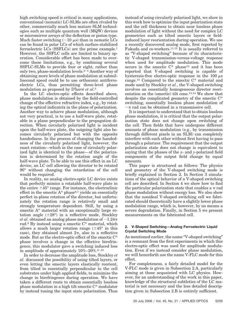
optic effect is the azimuthal rotation of the director(and the optical indicatrix) on the surface of the tiltcone having a cone angle 2�. The smectic C* phase isused in the so-called bookshelf geometry, with thesmectic layers homogeneously aligned perpendicularto the glass plates of the cell (see Fig. 1). Such a struc-ture is obtained by coating the inner surface of theglass plates with suitable alignment layers. In suffi-ciently thin cells the smectic C* helix is suppressed bysurface action giving a macroscopic polarization in thebulk. In the binary SSFLC device this polarization isperpendicular to the glass plates since the director isthen in one of the two possible orientations parallelwith the glass plates. By means of electric pulses thesystem can be switched between these two stablestates. In contrast, for the V-shaped switching modethe bookshelf structured cell is constructed such thatthe macroscopic polarization is parallel to the glassplates, i.e., the zero-field state corresponds to the di-rector being on the bottom (or top) of the tilt cone, asshown by the solid director in Fig. 1. When applying anelectric field perpendicular to the glass plates there isan immediate torque on Ps that in turn reorients thedirector on the surface of the tilt cone until the mini-mum in the total electrostatic and elastic energy isreached (see Fig. 2). For sufficiently high voltages Ps
becomes parallel with the applied field. Ideally, allpositions of the director on the tilt cone are accessibleby tuning the voltage amplitude and thus the effect isperfectly analog. The understanding of the V-shapedswitching mode has recently been taken further,14,16–20
targeting the effects of cell surfaces and of ionic impu-rities. The V-FLC structure is promoted by strong po-lar surface anchoring in combination with a high valueof spontaneous polarization of the smectic C* materi-al.13 The zero-field state, with Ps parallel to the cellsurfaces, is further stabilized by increasing the thick-ness of the insulating surface layers between the elec-trodes and the alignment layer.14,16,18
B. Optical Behavior of the V-Shaped-SwitchingFerroelectric Liquid Crystal Mode
In short, the electro-optic effect of the V-shapedswitching mode is the movement of the director (theslow axis of the index ellipsoid) on the surface of thetilt cone, as depicted in Fig. 2. At zero applied field
Fig. 1. Schematic of the V-FLC structure. The material is in thebookshelf geometry, i.e., the smectic layers of the smectic C* phaseare homogeneously aligned perpendicular to the glass plates of thecell. The director can be switched into any position on the tilt cone,having an angle of 2�. The spontaneous polarization Ps is tangen-tial to the tilt cone surface.
Fig. 2. Orientation of the director for (a) no ap-plied electric field, (b) a medium-strength electricfield, and (c) a strong electric field.
the director is oriented as in Fig. 2(a), with the spon-taneous electric polarization, Ps, of the LC materialoriented parallel to the glass plates. When applyingan external electric field, a torque acts on the polar-ization Ps and the director is reoriented to a newposition on the surface of the cone, which can bearbitrarily chosen using the appropriate strength ofthe applied field. For sufficiently high electric fields,the spontaneous polarization becomes perpendicularto the glass plates, Fig. 2(c). When the director moveson the surface of the cone, the projection of the effec-tive slow axis reorients in the plane of the cell with asimultaneous analog change in the effective birefrin-gence for light passing through the cell. The mini-mum and maximum values of the effectivebirefringence is obtained at zero field and in the fullyswitched states, respectively.
3. V-Shaped-Switching Ferroelectric Liquid CrystalMode for Phase Modulation
In this section we start with a short description ofhow the molecular orientation in the V-FLC materialwas modeled, followed by the model for the entireV-FLC cell with some simulation results.
A. Modeling the Optics of the V-Shaped-SwitchingFerroelectric Liquid Crystal Mode
For simplicitly, let us consider the smectic C* mate-rial to be locally uniaxial, i.e., we have one principalrefractive index parallel with and one perpendicularto the director, denoted by ne (slow axis) and no (fastaxis), respectively. The geometry is explained inFig. 3. In the (x, y, z) frame the director is given by
n � �xd, yd, zd� � �sin � cos �, cos �, sin � sin ��,(1)
where � describes the azimuthal position of the di-rector on the tilt cone, limited to 0 � �, and � isthe tilt cone half-angle that is a constant of the LCmaterial and is thus not changed by the applied field.
To simulate the electro-optics of the V-FLC modewe need to calculate two characteristic angles for thedirector orientation: the in-plane rotation angle � andthe polar angle � of the director with respect to thecell plane, both depicted in Fig. 3, which are functionsof the azimuthal angle �. The in-plane rotation � isthe apparent rotation of the slow axis as experiencedby the light. It is the angle between the y axis and theprojection of the director onto the (x, y) plane as in-dicated in Fig. 3. We thus have
tan � �xd
yd�
sin � cos �
cos �. (2)
The angle � determines the effective length of theslow axis as experienced by the light. It is the anglebetween the director and its projection onto the (x, y)
plane, thus
sin � �zd
n � sin � sin �. (3)
Because the effective length of the slow axis de-creases with increasing �, the optical field polarizedalong this axis experiences an effective refractivene��� lower than ne,
ne��� �neno
�ne2 cos2 � � ne
2 sin2 �, (4)
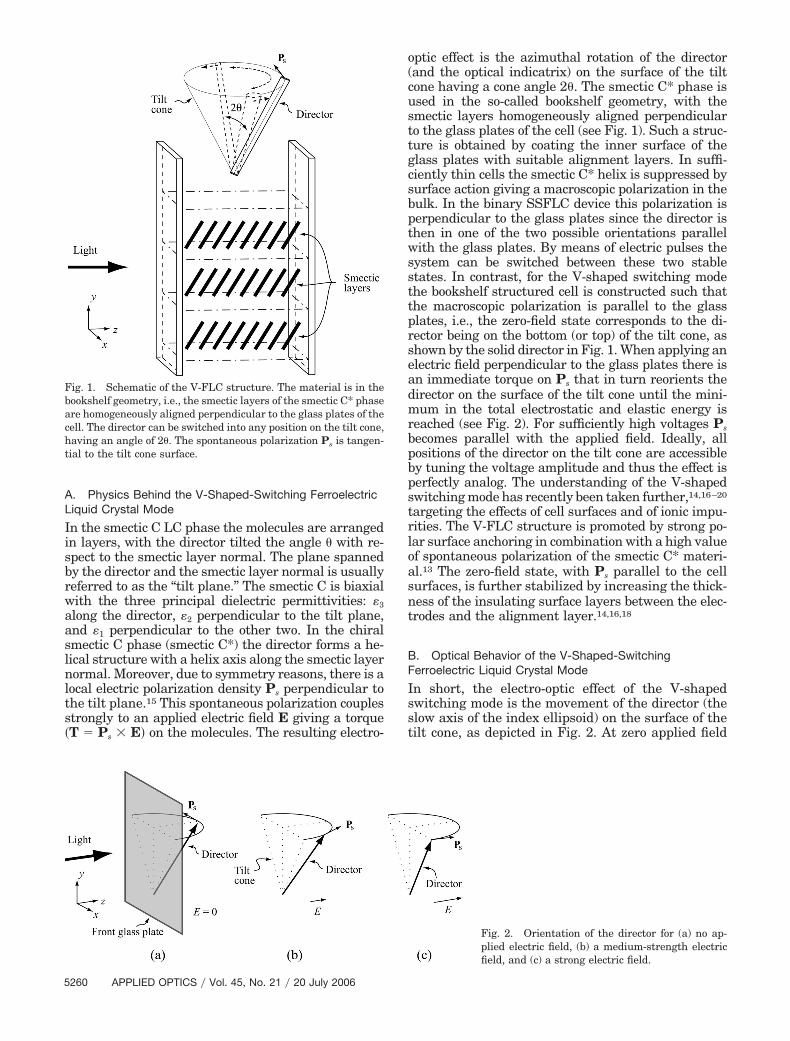
while the optical field polarized in the perpendiculardirection experiences the ordinary refractive indexno, which is independent of �. In Fig. 4 the effec-tive refractive index is plotted as a function of thein-plane angle � for the ideal case � � 45° and for� � 38° (the measured value for our fabricated cell);in both cases the refractive indices are taken to beno � 1.50 and ne � 1.65, which are typical values forthe used type of LC material.
B. Cell Modeling
In the simulations, the cell is treated as a homoge-neous but anisotropic medium, i.e., we neglect thefact that the molecules closest to the substrate sur-faces tend to orient parallel to the surface. In mate-rials with a large polarization Ps, these surfaceregions are generally thin compared to the thicknessof the cell13 and can be neglected as a first approxi-mation. In other words, the V-FLC cell is assumed toact as a uniaxial wave plate, with an effective cell
Fig. 3. Schematic of the geometry of the V-FLC cell, with thedirector n, the tilt half-cone on which the director is confined, andthe polarization vector Ps. Light travels in the positive z directionand is polarized in the (x, y) plane. The glass substrates, whichconfine the LC material, are parallel with the (x, y) plane. Thevoltage over the LC cell causes an electric field along the z axis thatrotates the director along the cone.
thickness negligibly smaller than the actual thick-ness of the V-FLC cell, and whose rotation � andretardation � are given by the azimuthal position � ofthe director, which in turn is a function of the electricfield applied across the cell.
The retardation of the V-FLC cell as a function ofthe in-plane rotation angle � is given by
� �2�
� �ne��� � no�d, (5)
where d is the effective cell thickness and � is thefree-space wavelength. The simulations are based ona Jones calculus of polarized light propagatingthrough birefringent media. A Jones vector describ-ing an optical field Eopt with an arbitrary polarizationstate can be written as
Eopt � Ex
Ey� cos �
sin � exp�i��, (6)
where determines the relative strengths of the x- andy-polarized field components, and describes thephase difference between the field components. To de-scribe all possible polarization states, these two anglescover the variable space described by 0 � ��2 and0 � 2�. By using the Stokes parameters21
s1 � Ex 2 � Ey 2 � cos2 � � sin2 �, (7)
s2 � 2 Ex Ey cos�arg Ey � arg Ex�� 2 cos � sin � cos �, (8)
s3 � 2 Ex Ey sin�arg Ey � arg Ex�� 2 cos � sin � sin �, (9)
the field described by Eq. (6) may be visualized on the
Poincaré sphere where �s1, s2, s3� are the coordinatesof the polarization state on the sphere (see Fig. 5).Further, the output polarization state obtained whenthe incident field Ein is transmitted through theV-FLC cell is given by
Eout � R����WWP���R���Ein, (10)
where WWP��� is the Jones matrix describing a waveplate with a retardation � and R is known as therotation matrix. A more detailed description of Jonescalculus on LC devices can be found in Ref. 22.
C. Initial Simulations—Comparison with aHalf-Wave Plate
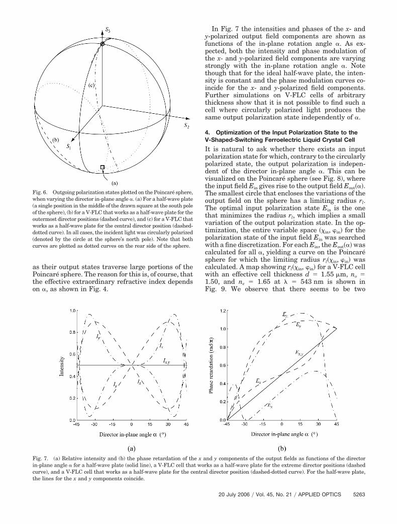
With the described model we compared the behaviorof a V-FLC cell with that of the rotatable half-waveplate assuming circular input polarization. We sim-ulated two different V-FLC cells, first a cell with aneffective thickness chosen such that the cell functionsas a half-wave plate when the director is in its out-ermost positions �� � 0 or � � �). The second V-FLCcell has a larger effective thickness such that it worksas a half-wave plate when the director is in its centralposition �� � ��2�. The V-FLC material was assumedto have a tilt cone half-angle of 45°. The results ofthese simulations are shown in Figs. 6 and 7.
In Fig. 6 the output polarization states are plottedon the Poincaré sphere as functions of the in-planeangle � (which for the half-wave plate equals therotation angle). By inspection of Fig. 6, it is clear thatcircularly polarized input produces the same outputpolarization state irrespective of the rotation angle ofthe half-wave retarder plate. This is, as explained,the condition for lossless operation. Unfortunately,but not unexpectedly, the figure also shows that thisis not the case, not even close, for the two V-FLC cells
Fig. 4. Effective refractive indices for V-FLC materials with no �1.50 and ne � 1.65 as function of the angle �. Shown are theordinary and extraordinary refractive indices (dashed-dotted anddashed lines, respectively) and the rotation-angle dependent effec-tive extraordinary indices for materials with � � 45° and � � 38°(solid and dotted curves, respectively).
Fig. 5. Poincaré sphere representation of the angles and describing a general polarization state E.
as their output states traverse large portions of thePoincaré sphere. The reason for this is, of course, thatthe effective extraordinary refractive index dependson �, as shown in Fig. 4.
In Fig. 7 the intensities and phases of the x- andy-polarized output field components are shown asfunctions of the in-plane rotation angle �. As ex-pected, both the intensity and phase modulation ofthe x- and y-polarized field components are varyingstrongly with the in-plane rotation angle �. Notethough that for the ideal half-wave plate, the inten-sity is constant and the phase modulation curves co-incide for the x- and y-polarized field components.Further simulations on V-FLC cells of arbitrarythickness show that it is not possible to find such acell where circularly polarized light produces thesame output polarization state independently of �.
4. Optimization of the Input Polarization State to theV-Shaped-Switching Ferroelectric Liquid Crystal Cell
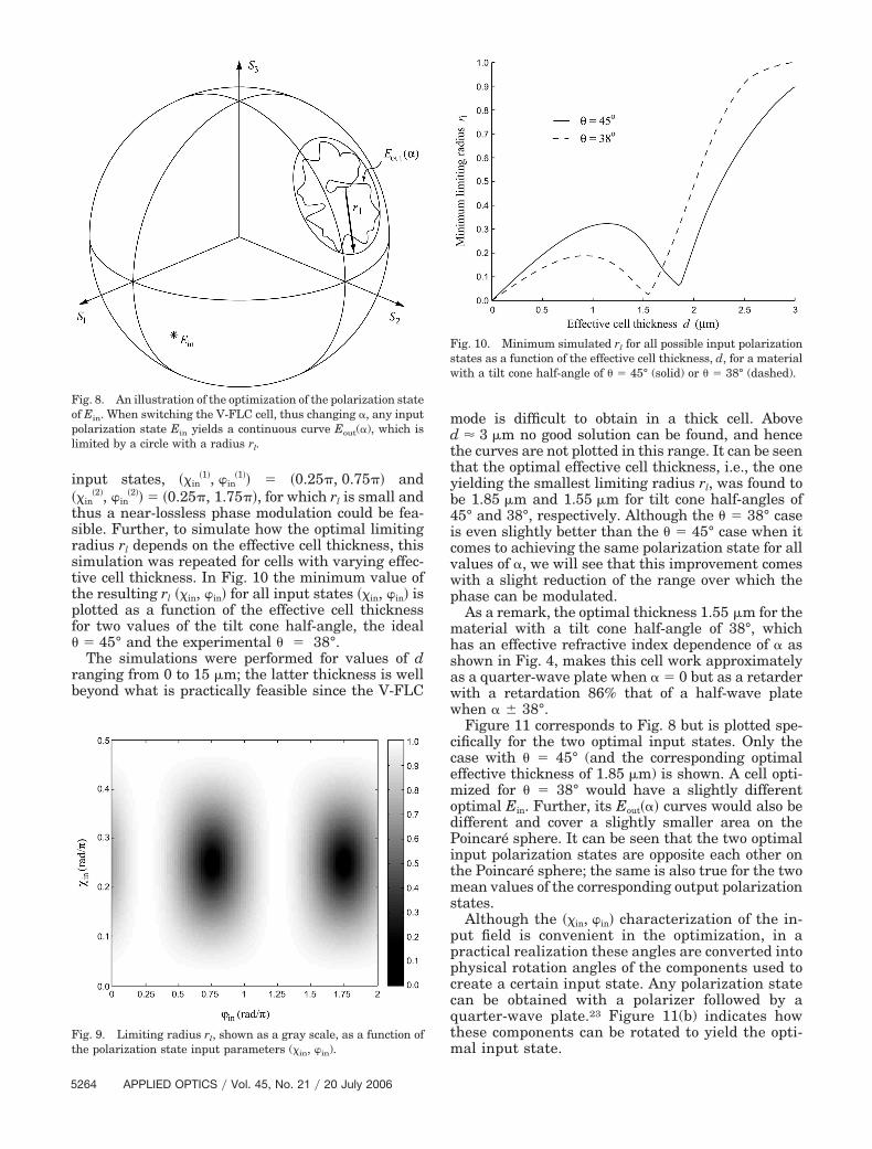
It is natural to ask whether there exists an inputpolarization state for which, contrary to the circularlypolarized state, the output polarization is indepen-dent of the director in-plane angle �. This can bevisualized on the Poincaré sphere (see Fig. 8), wherethe input field Ein gives rise to the output field Eout���.The smallest circle that encloses the variations of theoutput field on the sphere has a limiting radius rl.The optimal input polarization state Ein is the onethat minimizes the radius rl, which implies a smallvariation of the output polarization state. In the op-timization, the entire variable space ��in, �in� for thepolarization state of the input field Ein was searchedwith a fine discretization. For each Ein, the Eout��� wascalculated for all �, yielding a curve on the Poincarésphere for which the limiting radius rl��in, �in� wascalculated. A map showing rl��in, �in� for a V-FLC cellwith an effective cell thickness d � 1.55 �m, no �1.50, and ne � 1.65 at � � 543 nm is shown inFig. 9. We observe that there seems to be two
Fig. 6. Outgoing polarization states plotted on the Poincaré sphere,when varying the director in-plane angle �. (a) For a half-wave plate(a single position in the middle of the drawn square at the south poleof the sphere), (b) for a V-FLC that works as a half-wave plate for theoutermost director positions (dashed curve), and (c) for a V-FLC thatworks as a half-wave plate for the central director position (dashed-dotted curve). In all cases, the incident light was circularly polarized(denoted by the circle at the sphere’s north pole). Note that bothcurves are plotted as dotted curves on the rear side of the sphere.
Fig. 7. (a) Relative intensity and (b) the phase retardation of the x and y components of the output fields as functions of the directorin-plane angle � for a half-wave plate (solid line), a V-FLC cell that works as a half-wave plate for the extreme director positions (dashedcurve), and a V-FLC cell that works as a half-wave plate for the central director position (dashed-dotted curve). For the half-wave plate,the lines for the x and y components coincide.
�2�, �in�2�� � �0.25�, 1.75��, for which rl is small and
thus a near-lossless phase modulation could be fea-sible. Further, to simulate how the optimal limitingradius rl depends on the effective cell thickness, thissimulation was repeated for cells with varying effec-tive cell thickness. In Fig. 10 the minimum value ofthe resulting rl ��in, �in� for all input states ��in, �in� isplotted as a function of the effective cell thicknessfor two values of the tilt cone half-angle, the ideal� � 45° and the experimental � � 38°.
The simulations were performed for values of dranging from 0 to 15 �m; the latter thickness is wellbeyond what is practically feasible since the V-FLC
mode is difficult to obtain in a thick cell. Aboved � 3 �m no good solution can be found, and hencethe curves are not plotted in this range. It can be seenthat the optimal effective cell thickness, i.e., the oneyielding the smallest limiting radius rl, was found tobe 1.85 �m and 1.55 �m for tilt cone half-angles of45° and 38°, respectively. Although the � � 38° caseis even slightly better than the � � 45° case when itcomes to achieving the same polarization state for allvalues of �, we will see that this improvement comeswith a slight reduction of the range over which thephase can be modulated.
As a remark, the optimal thickness 1.55 �m for thematerial with a tilt cone half-angle of 38°, whichhas an effective refractive index dependence of � asshown in Fig. 4, makes this cell work approximatelyas a quarter-wave plate when � � 0 but as a retarderwith a retardation 86% that of a half-wave platewhen � � 38°.
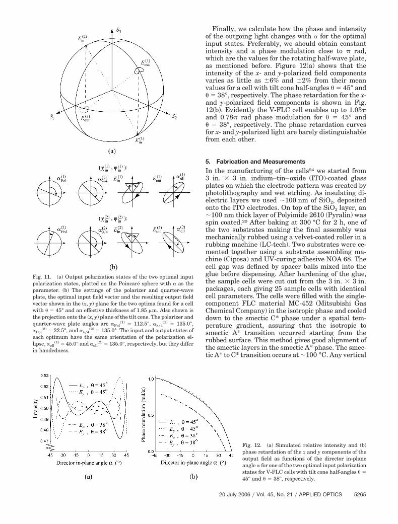
Figure 11 corresponds to Fig. 8 but is plotted spe-cifically for the two optimal input states. Only thecase with � � 45° (and the corresponding optimaleffective thickness of 1.85 �m) is shown. A cell opti-mized for � � 38° would have a slightly differentoptimal Ein. Further, its Eout��� curves would also bedifferent and cover a slightly smaller area on thePoincaré sphere. It can be seen that the two optimalinput polarization states are opposite each other onthe Poincaré sphere; the same is also true for the twomean values of the corresponding output polarizationstates.
Although the ��in, �in� characterization of the in-put field is convenient in the optimization, in apractical realization these angles are converted intophysical rotation angles of the components used tocreate a certain input state. Any polarization statecan be obtained with a polarizer followed by aquarter-wave plate.23 Figure 11(b) indicates howthese components can be rotated to yield the opti-mal input state.
Fig. 8. An illustration of the optimization of the polarization stateof Ein. When switching the V-FLC cell, thus changing �, any inputpolarization state Ein yields a continuous curve Eout(�), which islimited by a circle with a radius rl.
Fig. 9. Limiting radius rl, shown as a gray scale, as a function ofthe polarization state input parameters (in, in).
Fig. 10. Minimum simulated rl for all possible input polarizationstates as a function of the effective cell thickness, d, for a materialwith a tilt cone half-angle of � � 45° (solid) or � � 38° (dashed).
Finally, we calculate how the phase and intensityof the outgoing light changes with � for the optimalinput states. Preferably, we should obtain constantintensity and a phase modulation close to � rad,which are the values for the rotating half-wave plate,as mentioned before. Figure 12(a) shows that theintensity of the x- and y-polarized field componentsvaries as little as �6% and �2% from their meanvalues for a cell with tilt cone half-angles � � 45° and� � 38°, respectively. The phase retardation for the x-and y-polarized field components is shown in Fig.12(b). Evidently the V-FLC cell enables up to 1.03�and 0.78� rad phase modulation for � � 45° and� � 38°, respectively. The phase retardation curvesfor x- and y-polarized light are barely distinguishablefrom each other.
5. Fabrication and Measurements
In the manufacturing of the cells24 we started from3 in. � 3 in. indium–tin–oxide (ITO)-coated glassplates on which the electrode pattern was created byphotolithography and wet etching. As insulating di-electric layers we used �100 nm of SiO2, depositedonto the ITO electrodes. On top of the SiO2 layer, an�100 nm thick layer of Polyimide 2610 (Pyralin) wasspin coated.20 After baking at 300 °C for 2 h, one ofthe two substrates making the final assembly wasmechanically rubbed using a velvet-coated roller in arubbing machine (LC-tech). Two substrates were ce-mented together using a substrate assembling ma-chine (Ciposa) and UV-curing adhesive NOA 68. Thecell gap was defined by spacer balls mixed into theglue before dispensing. After hardening of the glue,the sample cells were cut out from the 3 in. � 3 in.packages, each giving 25 sample cells with identicalcell parameters. The cells were filled with the single-component FLC material MC-452 (Mitsubishi GasChemical Company) in the isotropic phase and cooleddown to the smectic C* phase under a spatial tem-perature gradient, assuring that the isotropic tosmectic A* transition occurred starting from therubbed surface. This method gives good alignment ofthe smectic layers in the smectic A* phase. The smec-tic A* to C* transition occurs at �100 °C. Any vertical
Fig. 11. (a) Output polarization states of the two optimal inputpolarization states, plotted on the Poincaré sphere with � as theparameter. (b) The settings of the polarizer and quarter-waveplate, the optimal input field vector and the resulting output fieldvector shown in the (x, y) plane for the two optima found for a cellwith � � 45° and an effective thickness of 1.85 m. Also shown isthe projection onto the (x, y) plane of the tilt cone. The polarizer andquarter-wave plate angles are �Pol
(1) � 112.5°, ���4(1) � 135.0°,
�Pol(2) � 22.5°, and ���4
(2) � 135.0°. The input and output states ofeach optimum have the same orientation of the polarization el-lipse, �ell
(1) � 45.0° and �ell(2) � 135.0°, respectively, but they differ
in handedness.
Fig. 12. (a) Simulated relative intensity and (b)phase retardation of the x and y components of theoutput field as functions of the director in-planeangle � for one of the two optimal input polarizationstates for V-FLC cells with tilt cone half-angles � �45° and � � 38°, respectively.
chevrons25 in the smectic C* structure were straight-ened out by applying electric fields higher than thefields necessary for full switching. After this initialfield treatment, the cells exhibited V-shaped switch-ing.
In a freshly made cell of MC-452, hysteresis-freeV-shaped switching can be obtained up to above200 Hz at room temperature with a triangular wavedrive, with pulse response times of approximately 1ms at room temperature and approximately 100 �s atapproximately 80 °C.20 After a few days, a smallamount of hysteresis can sometimes appear in theresponse. This could possibly be due to partial relax-ation into bistable domains with or without chevrons,an effect that is still under study.
A. Characterizing the V-Shaped-Switching FerroelectricLiquid Crystal Cell
The tilt cone half-angle � was determined from theamplitude electro-optic response for a cell placed androtated between crossed polarizers. For the fabri-cated cell, the tilt cone half-angle was found to be 38°and 39° for the two sides of the cone, respectively,indicating that the cell is slightly asymmetric, i.e.,the zero-field position of the director is slightly off theideal position on the bottom of the tilt cone.
To determine the optimal operating wavelength,the retardation of the V-FLC cell was analyzed. Thiswas done indirectly by measuring intensity varia-tions and not by directly measuring the phase retar-dation. Again the V-FLC cell was inserted betweenpolarizers. The voltage over the cell was either highpositive, high negative, or zero. Thus the directorwas either in one of its extreme positions �� � 0 or� � �) or in its central position �� � ��2�. For eachvoltage the cell was positioned such that the firstpolarizer and the director [or the projection of thedirector onto the (x, y) plane for the zero voltage case]make an angle of 45°. This means that if the cellworks as a half-wave plate the polarization vector ofthe incident light should be “reflected” in the axis ofthe cell so that the light out from the cell is alsolinearly polarized but at a 90° angle to its originalpolarization. Thus as the second polarizer is rotated,the output intensity is going to exhibit a full modu-
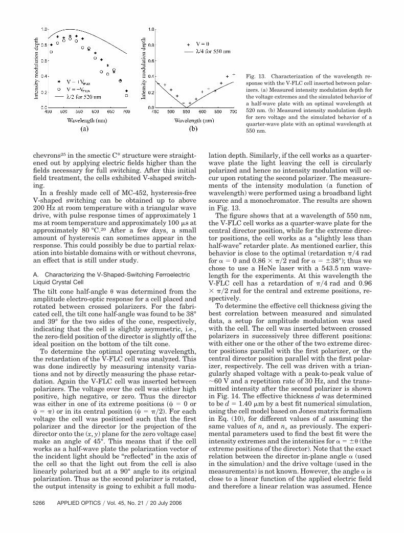
lation depth. Similarly, if the cell works as a quarter-wave plate the light leaving the cell is circularlypolarized and hence no intensity modulation will oc-cur upon rotating the second polarizer. The measure-ments of the intensity modulation (a function ofwavelength) were performed using a broadband lightsource and a monochromator. The results are shownin Fig. 13.
The figure shows that at a wavelength of 550 nm,the V-FLC cell works as a quarter-wave plate for thecentral director position, while for the extreme direc-tor positions, the cell works as a “slightly less thanhalf-wave” retarder plate. As mentioned earlier, thisbehavior is close to the optimal (retardation ��4 radfor � � 0 and 0.86 � ��2 rad for � � �38°); thus wechose to use a HeNe laser with a 543.5 nm wave-length for the experiments. At this wavelength theV-FLC cell has a retardation of ��4 rad and 0.96� ��2 rad for the central and extreme positions, re-spectively.
To determine the effective cell thickness giving thebest correlation between measured and simulateddata, a setup for amplitude modulation was usedwith the cell. The cell was inserted between crossedpolarizers in successively three different positions:with either one or the other of the two extreme direc-tor positions parallel with the first polarizer, or thecentral director position parallel with the first polar-izer, respectively. The cell was driven with a trian-gularly shaped voltage with a peak-to-peak value of�60 V and a repetition rate of 30 Hz, and the trans-mitted intensity after the second polarizer is shownin Fig. 14. The effective thickness d was determinedto be d � 1.40 �m by a best fit numerical simulation,using the cell model based on Jones matrix formalismin Eq. (10), for different values of d assuming thesame values of ne and no as previously. The experi-mental parameters used to find the best fit were theintensity extremes and the intensities for � � �� (theextreme positions of the director). Note that the exactrelation between the director in-plane angle � (usedin the simulation) and the drive voltage (used in themeasurements) is not known. However, the angle � isclose to a linear function of the applied electric fieldand therefore a linear relation was assumed. Hence
Fig. 13. Characterization of the wavelength re-sponse with the V-FLC cell inserted between polar-izers. (a) Measured intensity modulation depth forthe voltage extremes and the simulated behavior ofa half-wave plate with an optimal wavelength at520 nm. (b) Measured intensity modulation depthfor zero voltage and the simulated behavior of aquarter-wave plate with an optimal wavelength at550 nm.
the slope of the simulated curve cannot be expected tofully agree with the measurements. Further, the“double” experimental values for a given voltage re-veal that a slight hysteresis is present, as discussedearlier.
B. Finding the Optimal Input State
In the numerical optimization, we used the limitingradius on the Poincaré sphere, rl, as a measure of howwell the output polarization state was maintained fordifferent values of �, or equivalently, cell voltages.Experimentally, it is more convenient to use othermeasures than rl; we simply used the variations inthe x- and y-polarized intensities, measured using apolarizer after the cell, when the cell voltage waschanged. Obviously, if the output polarization statefrom the LC cell does not change, neither will the x-and y-polarized intensities. In the setup, a polariza-tion state generator (PSG) was inserted in front of thecell. The PSG is simply a polarizer followed by aquarter-wave plate and permits an arbitrary settingof the polarization incident on the cell. The physicalorientation, �Pol and ���4, of the polarizer and quarter-wave plate can be translated into the input polariza-tion state angles �in and �in and vice versa as shownin Ref. 23. The result from such a series of measure-ments is shown in Fig. 15. To accurately determinethe optimal input states, the incremental steps in �inand �in were smaller in the vicinity of the two min-ima, for which the polarization states were found tobe ��in
�1�, �in�1�� � �0.266�, 0.768�� and ��in
�2�, �in�2��
� �0.237�, 1.774��. To our satisfaction, Fig. 15closely resembles Fig. 9, which shows the correspond-ing results for the numerical simulation, with theminima ��in
�1�, �in�1�� � �0.25�, 0.75�� and ��in
�2�, �in�2��
� �0.25�, 1.75��.
C. Phase and Amplitude Modulation Measurements
The phase modulation was measured with a Mach–Zehnder interferometer; the setup is shown inFig. 16. The polarizer P1 and the quarter-wave plateQWP of the PSG were oriented such as to generateone of the two optimal input polarization states ontothe V-FLC cell. Polarizer P2, placed outside the inter-ferometer, was used to select either the x- ory-polarized field components for observation. Thethird polarizer, P3, was used to attenuate the inten-sity in the reference arm such that it would equal theintensity in the measuring arm in order to obtainhigh-contrast interference fringes. The fringes thatformed after the beam combiner were imaged andmagnified by a lens L onto a plane in which two smallphotodiodes, detectors D1 and D2, were inserted. Theseparation between D1 and D2 corresponded to a 90°phase difference in the sinusoidal fringe pattern. Inthis way the phase modulation could be continuouslymonitored as a position on a circular track on anoscilloscope where the horizontal deflection comesfrom D1 and the vertical deflection comes from D2.
Fig. 14. Measured intensity after the second (crossed) polarizerfor the cell being rotated such that the first polarizer has a trans-mission direction making an angle of 0 and �� with the y axis asdefined by Fig. 3. The curves correspond to the simulations for acell with an effective cell thickness of 1.40 m.
Fig. 15. Measured variation of the output polarization state dur-ing analog switching of the V-FLC cell as a function of the polar-ization state input parameters (in, in). The intensity representedby the gray scale is ��Ix
2��Iy2 where �Ix is the maximum intensity
change in the x-polarized intensity as the cell voltage is changedover its full range, and likewise for �Iy.
The amplitude modulation for the optimal input po-larization states was measured by blocking the ref-erence arm of the interferometer. In this case, aphotodiode was inserted immediately after P2.
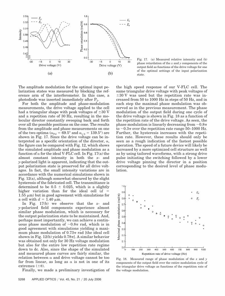
For both the amplitude and phase-modulationmeasurements, the drive voltage applied to the cellhad a triangular shape with peak voltages of �30 Vand a repetition rate of 30 Hz, resulting in the mo-lecular director constantly sweeping back and forthover all the possible positions on the cone. The resultsfrom the amplitude and phase measurements on oneof the two optima ��Pol � 69.5° and ���4 � 139.5°) areshown in Fig. 17. Since the drive voltage can be in-terpreted as a specific orientation of the director, �,the figure can be compared with Fig. 12, which showsthe simulated amplitude and phase modulation as afunction of � for the ideal V-FLC cell. In Fig. 17(a) thealmost constant intensity in both the x- andy-polarized light is apparent, indicating that the out-put polarization state is preserved for all drive volt-ages. In fact, the small intensity variations are inaccordance with the numerical simulations shown inFig. 12(a), although somewhat obscured by the slighthysteresis of the fabricated cell. The transmittance isdetermined to be 0.5 � 0.025, which is a slightlyhigher variation than for the ideal cell �d �1.55 �m� but in good agreement with simulations fora cell with d � 1.40 �m.
In Fig. 17(b) we observe that the x- andy-polarized field components experience almostsimilar phase modulation, which is necessary forthe output polarization state to be maintained. And,perhaps most importantly, we can achieve a contin-uous phase modulation of �0.8� rad, which is ingood agreement with simulations yielding a maxi-mum phase modulation of 0.73� rad [the ideal cellshown in Fig. 12(b) yields 0.78�]. A similar behaviorwas obtained not only for 30 Hz voltage modulationbut also for the entire low repetition rate regimedown to dc. Also, since the shape of the simulatedand measured phase curves are fairly similar, therelation between � and drive voltage cannot be toofar from linear, as long as � is not in one of itsextremes (��).
Finally, we made a preliminary investigation of
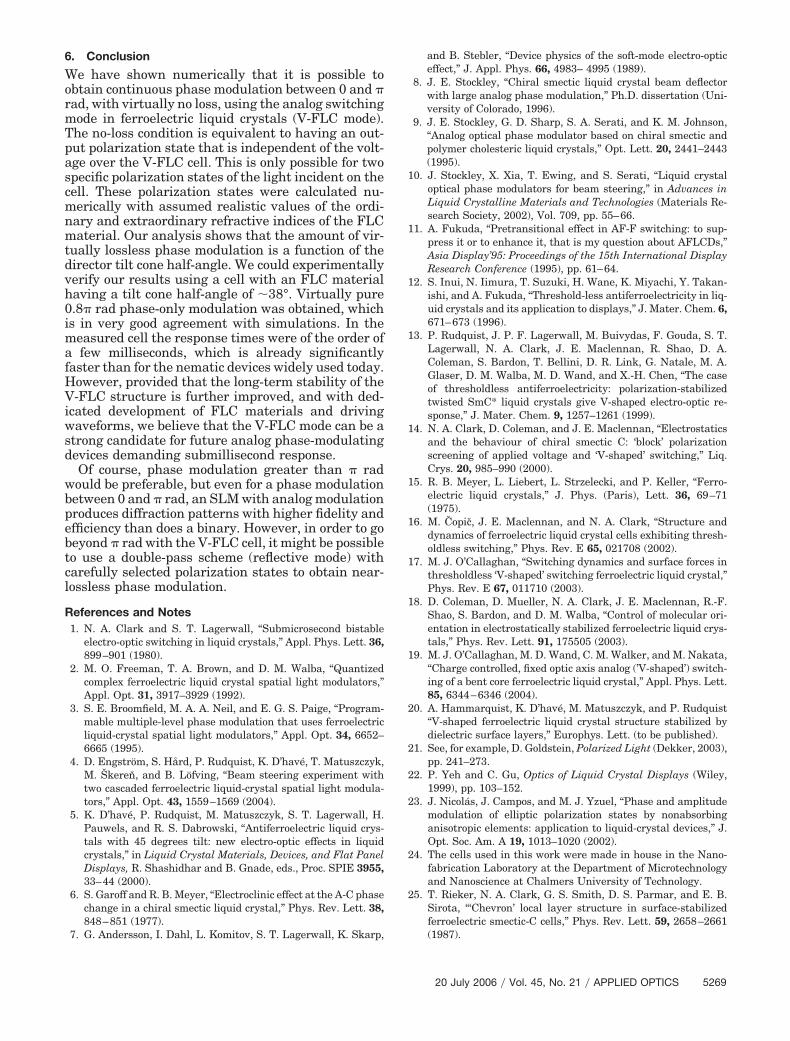
the high speed response of our V-FLC cell. Thesame triangular drive voltage with peak voltages of�30 V was used but the repetition rate was in-creased from 50 to 1000 Hz in steps of 50 Hz, and ineach step the maximal phase modulation was ob-served as in the previous measurement. The phasemodulation of the output field during one cycle ofthe drive voltage is shown in Fig. 18 as a function ofthe repetition rate of the drive voltage. As seen, thephase modulation is linearly decreasing from �0.8�to �0.3� over the repetition rate range 50–1000 Hz.Further, the hysteresis increases with the repeti-tion rate. However, these results should only beseen as a rough indication of the fastest possibleoperation. The speed of a future device will likely beincreased by a more optimized cell structure as wellas by using tailored waveforms, with a strong drivepulse initiating the switching followed by a lowerdrive voltage pinning the director in a positioncorresponding to the desired level of phase modu-lation.
Fig. 17. (a) Measured relative intensity and (b)phase retardation of the x and y components of theoutput field as functions of the drive voltage for oneof the optimal settings of the input polarizationstate.
Fig. 18. Measured range of phase modulation of the x and ycomponents of the output field over the entire modulation cycle ofthe triangular drive voltage as functions of the repetition rate ofthe voltage modulation.
We have shown numerically that it is possible toobtain continuous phase modulation between 0 and �rad, with virtually no loss, using the analog switchingmode in ferroelectric liquid crystals (V-FLC mode).The no-loss condition is equivalent to having an out-put polarization state that is independent of the volt-age over the V-FLC cell. This is only possible for twospecific polarization states of the light incident on thecell. These polarization states were calculated nu-merically with assumed realistic values of the ordi-nary and extraordinary refractive indices of the FLCmaterial. Our analysis shows that the amount of vir-tually lossless phase modulation is a function of thedirector tilt cone half-angle. We could experimentallyverify our results using a cell with an FLC materialhaving a tilt cone half-angle of �38°. Virtually pure0.8� rad phase-only modulation was obtained, whichis in very good agreement with simulations. In themeasured cell the response times were of the order ofa few milliseconds, which is already significantlyfaster than for the nematic devices widely used today.However, provided that the long-term stability of theV-FLC structure is further improved, and with ded-icated development of FLC materials and drivingwaveforms, we believe that the V-FLC mode can be astrong candidate for future analog phase-modulatingdevices demanding submillisecond response.
Of course, phase modulation greater than � radwould be preferable, but even for a phase modulationbetween 0 and � rad, an SLM with analog modulationproduces diffraction patterns with higher fidelity andefficiency than does a binary. However, in order to gobeyond � rad with the V-FLC cell, it might be possibleto use a double-pass scheme (reflective mode) withcarefully selected polarization states to obtain near-lossless phase modulation.
References and Notes1. N. A. Clark and S. T. Lagerwall, “Submicrosecond bistable
electro-optic switching in liquid crystals,” Appl. Phys. Lett. 36,899–901 (1980).
2. M. O. Freeman, T. A. Brown, and D. M. Walba, “Quantizedcomplex ferroelectric liquid crystal spatial light modulators,”Appl. Opt. 31, 3917–3929 (1992).
3. S. E. Broomfield, M. A. A. Neil, and E. G. S. Paige, “Program-mable multiple-level phase modulation that uses ferroelectricliquid-crystal spatial light modulators,” Appl. Opt. 34, 6652–6665 (1995).
4. D. Engström, S. Hård, P. Rudquist, K. D’havé, T. Matuszczyk,M. Škeren, and B. Löfving, “Beam steering experiment withtwo cascaded ferroelectric liquid-crystal spatial light modula-tors,” Appl. Opt. 43, 1559–1569 (2004).
5. K. D’havé, P. Rudquist, M. Matuszczyk, S. T. Lagerwall, H.Pauwels, and R. S. Dabrowski, “Antiferroelectric liquid crys-tals with 45 degrees tilt: new electro-optic effects in liquidcrystals,” in Liquid Crystal Materials, Devices, and Flat PanelDisplays, R. Shashidhar and B. Gnade, eds., Proc. SPIE 3955,33–44 (2000).
6. S. Garoff and R. B. Meyer, “Electroclinic effect at the A-C phasechange in a chiral smectic liquid crystal,” Phys. Rev. Lett. 38,848–851 (1977).
7. G. Andersson, I. Dahl, L. Komitov, S. T. Lagerwall, K. Skarp,
and B. Stebler, “Device physics of the soft-mode electro-opticeffect,” J. Appl. Phys. 66, 4983– 4995 (1989).
8. J. E. Stockley, “Chiral smectic liquid crystal beam deflectorwith large analog phase modulation,” Ph.D. dissertation (Uni-versity of Colorado, 1996).
9. J. E. Stockley, G. D. Sharp, S. A. Serati, and K. M. Johnson,“Analog optical phase modulator based on chiral smectic andpolymer cholesteric liquid crystals,” Opt. Lett. 20, 2441–2443(1995).
10. J. Stockley, X. Xia, T. Ewing, and S. Serati, “Liquid crystaloptical phase modulators for beam steering,” in Advances inLiquid Crystalline Materials and Technologies (Materials Re-search Society, 2002), Vol. 709, pp. 55–66.
11. A. Fukuda, “Pretransitional effect in AF-F switching: to sup-press it or to enhance it, that is my question about AFLCDs,”Asia Display’95: Proceedings of the 15th International DisplayResearch Conference (1995), pp. 61–64.
12. S. Inui, N. Iimura, T. Suzuki, H. Wane, K. Miyachi, Y. Takan-ishi, and A. Fukuda, “Threshold-less antiferroelectricity in liq-uid crystals and its application to displays,” J. Mater. Chem. 6,671–673 (1996).
13. P. Rudquist, J. P. F. Lagerwall, M. Buivydas, F. Gouda, S. T.Lagerwall, N. A. Clark, J. E. Maclennan, R. Shao, D. A.Coleman, S. Bardon, T. Bellini, D. R. Link, G. Natale, M. A.Glaser, D. M. Walba, M. D. Wand, and X.-H. Chen, “The caseof thresholdless antiferroelectricity: polarization-stabilizedtwisted SmC* liquid crystals give V-shaped electro-optic re-sponse,” J. Mater. Chem. 9, 1257–1261 (1999).
14. N. A. Clark, D. Coleman, and J. E. Maclennan, “Electrostaticsand the behaviour of chiral smectic C: ‘block’ polarizationscreening of applied voltage and ‘V-shaped’ switching,” Liq.Crys. 20, 985–990 (2000).
15. R. B. Meyer, L. Liebert, L. Strzelecki, and P. Keller, “Ferro-electric liquid crystals,” J. Phys. (Paris), Lett. 36, 69–71(1975).
16. M. Copic, J. E. Maclennan, and N. A. Clark, “Structure anddynamics of ferroelectric liquid crystal cells exhibiting thresh-oldless switching,” Phys. Rev. E 65, 021708 (2002).
17. M. J. O’Callaghan, “Switching dynamics and surface forces inthresholdless ‘V-shaped’ switching ferroelectric liquid crystal,”Phys. Rev. E 67, 011710 (2003).
18. D. Coleman, D. Mueller, N. A. Clark, J. E. Maclennan, R.-F.Shao, S. Bardon, and D. M. Walba, “Control of molecular ori-entation in electrostatically stabilized ferroelectric liquid crys-tals,” Phys. Rev. Lett. 91, 175505 (2003).
19. M. J. O’Callaghan, M. D. Wand, C. M. Walker, and M. Nakata,“Charge controlled, fixed optic axis analog (’V-shaped’) switch-ing of a bent core ferroelectric liquid crystal,” Appl. Phys. Lett.85, 6344–6346 (2004).
20. A. Hammarquist, K. D’havé, M. Matuszczyk, and P. Rudquist“V-shaped ferroelectric liquid crystal structure stabilized bydielectric surface layers,” Europhys. Lett. (to be published).
21. See, for example, D. Goldstein, Polarized Light (Dekker, 2003),pp. 241–273.
22. P. Yeh and C. Gu, Optics of Liquid Crystal Displays (Wiley,1999), pp. 103–152.
23. J. Nicolás, J. Campos, and M. J. Yzuel, “Phase and amplitudemodulation of elliptic polarization states by nonabsorbinganisotropic elements: application to liquid-crystal devices,” J.Opt. Soc. Am. A 19, 1013–1020 (2002).
24. The cells used in this work were made in house in the Nano-fabrication Laboratory at the Department of Microtechnologyand Nanoscience at Chalmers University of Technology.
25. T. Rieker, N. A. Clark, G. S. Smith, D. S. Parmar, and E. B.Sirota, “‘Chevron’ local layer structure in surface-stabilizedferroelectric smectic-C cells,” Phys. Rev. Lett. 59, 2658–2661(1987).


![[2004] Normalization and Lossless Join](https://static.documents.pub/doc/80x56/577cc6741a28aba7119e42b4/2004-normalization-and-lossless-join.jpg)


![Chapter 7 Lossless Compression ?· Chapter 7 Lossless Compression Algorithms ... (-0.46438) + (-0.9965)]…](https://static.documents.pub/doc/80x56/5b79b0717f8b9ae1328b47de/chapter-7-lossless-compression-chapter-7-lossless-compression-algorithms-.jpg)