Page 1
268
ISSN 13921207. MECHANIKA. 2018 Volume 24(2): 268277
Near Net Shape Spur Gear Forging Using Concave Preform
Necip Fazil YILMAZ*, Omer EYERCIOGLU**
*Mechanical Engineering Department, University of Gaziantep, 27310, Gaziantep, Turkey,
E-mail: [email protected]
**Mechanical Engineering Department, University of Gaziantep, 27310, Gaziantep, Turkey,
E-mail: [email protected]
http://dx.doi.org/10.5755/j01.mech.24.2.19334
1. Introduction
Precision forging gives shape to an initial billet,
which can be used directly as a part requiring little or no
further finishing. Directional alignment of the grains or fi-
bers, which form the outline of the product during the forg-
ing process, helps improve the mechanical properties of the
final forged part, imparting increased strength, ductility, and
resistance to the impact and fatigue of the metal [1].
Forming gears rather than cutting them has the ob-
vious advantage of greater utilization of raw material and
high productivity. Thus, the process of forming has greater
potential for large quantity batch production such as re-
quired by automotive companies and consumer goods in-
dustries. Despite these positive aspects, the economics of
fully formed spur and helical gears for power transmission
have not yet been proven to be acceptable and cannot be un-
til a robust processing route is established [2].
Overall performance of the forging operation re-
quires an understanding of not only the flow stress of the
material and frictional conditions but also the mode of flow
of the material. Success here depends on a thorough under-
standing of the metal flow during forging [3]. Although
many attempts have been made to acquire the knowledge
necessary to design the precision spur gear forging process,
preform design and design of dies [4-9] have been used to a
certain extent. Kiekbusch et al. [10] used FE analysis to cal-
culate the combined torsional mesh stiffness of spur gears.
Gear formation and failure analysis especially in gear tooth
crack growth analyzed by Podrug et al [11]. They proposed
that crack propagation in gear tooth is different according to
loading conditions. Ohga et al. [12] analyzed the forging of
spur gear with low carbon steel and low alloyed standard
steel in two steps to prevent the die failure by using second-
ary flow, which can reduce the working pressure. Arbak et
al. [13] compared the various preforms for hot forging of
bearing rings by considering the coupled thermo-mechani-
cal analysis. They concluded that there are different criteria
in determining the preform shape for different parts to pro-
long the tool wear and to prevent the tool fracture. Cai et al.
[14] discussed alternative tool designs, which may be used
on a press with only one moving slide and ejection system.
They examined the influence of different designs on metal
flow and load requirement through experiments and finite
element simulation. Chengliang et al. [15] studied on the di-
mensional accuracy of spur gears.
They proposed two different punch shapes to fulfill
the corners because of the inhomogeneous distribution of
metal blank.
The major problem associated with precision spur
gear forging is related mainly to the material flow and fric-
tion between the die and billet [16-17]. Under the load, billet
is bulging and getting contact with the die. The contact be-
gins nearly midpoint of the billet height and the contact area
increases with descending punch. Due to the friction effect,
forging load is increasing. Although high forging loads are
applied, it becomes very difficult to fill the corners of the
gear die. To utilize the advantage of preforms, punch dis-
placement and mode of metal flow should be well analyzed.
Therefore, this paper proposes concave preforms to over-
come insufficient corner filling problem with the application
of considerably less amount of forming load. Throughout
the analysis, three different types of preform geometry are
searched to fulfill the die cavity of spur gear dies. One of
them is the simple cylindrical form, and the other two pre-
forms are prepared in different concavity parameters. Dur-
ing the analysis, correlation between the relative average
load requirement and material flow behavior are captured.
Deformation mode of each preform is analyzed and demon-
strated with constant incremental steps. Radial flow velocity
distribution is an important indicator to be evaluated for
metal flow and, thus, forming load. To analyze the velocity
distribution, four different representative nodes are investi-
gated. According to the concavity, a feasible preform is sug-
gested for which the total forming load could be reduced by
34%. The predicted forging loads obtained by finite element
methods are shown to approximate the experimental results
at final filling up stage.
2. Die filling and problem definition
Because precision spur gear forging dies obtain
very high radial pressure during the process, it considerably
deforms in the radial direction. This radial deformation of
the die becomes an important factor influencing the dimen-
sional accuracy of the product. To obtain the product with
highly accurate dimension and within relatively less amount
of load, it is therefore essential to acquire some information
on the die filling and load stroke diagram. Hollow cylindri-
cal billets often are used to forge net-shape axisymmetric
and hollow parts such as gears used in power transmission
systems. The precision shape can be formed with parallel
bores by using completely closed dies with mandrels. Vari-
ous tool set designs are possible for finishing the forging of
gears in completely closed cavity dies [18]. An important
feature of completely closed forging dies is how the work-
piece is deformed to fill the die cavity. For the simple
shapes, the deformation mode can be identified by the order
of filling of top and bottom corners of the cavity. Fig. 1
Page 2
269
shows a workpiece enclosed in die cavity with the punch
and ejector [19].
Fig. 1 Deformation mode of billet: 1 - upper section, 2 -mid-
section, 3 - bottom section
The workpiece height initially gets smaller until
the outermost side of the workpiece touches the die wall
while the punch is moving downward. Barrelling almost
start at the middle of the workpiece. Therefore, friction be-
tween the die wall and the workpiece plays an important role
for the required forging load. After that point, the volume of
the part and contact area, shown by number 2 in Fig. 1, starts
to increase because of the increment in its height. This
means that more forging load is required. In the final stage,
the corners of the product remain a little bit circular.
The dimensions of the forged tooth form depend
not only on the expansion because of the elevated tempera-
tures of the billet and the tools but also on the elastic expan-
sion of the forging tools because of the radial pressure,
which is related to the forging load required to complete the
forged shape. In gear forging, the mid-section of the gear
teeth fills in advance of the top and bottom faces. It is in the
last stages of forging that the top and bottom corners of the
teeth are filled, and thus, this filling requires high forging
force. A significant increase in load arises when the work-
piece reaches the die. Near to the end of the process, forging
load increases sharply, and approximately 25% of the total
forming energy is consumed in this final stage [13].
Z.M. Hu and T.A. Dean [20] states that in the final
punch movement of 0.3 mm, 1.2% of the billet deformation
to fill the corner was accompanied by a load increase of
nearly 50%. Easing flow into the corners by die design tech-
niques or designing gears, which do not have sharp corners
can dramatically reduce forging load requirements and tool
stresses. The benefit will be less distortion, better dimen-
sional accuracy, and longer tool life. Another aspect of pre-
cision spur gear forging is extrusion of workpiece material
through the punch clearance when the bottom of the die cor-
ner is filled.
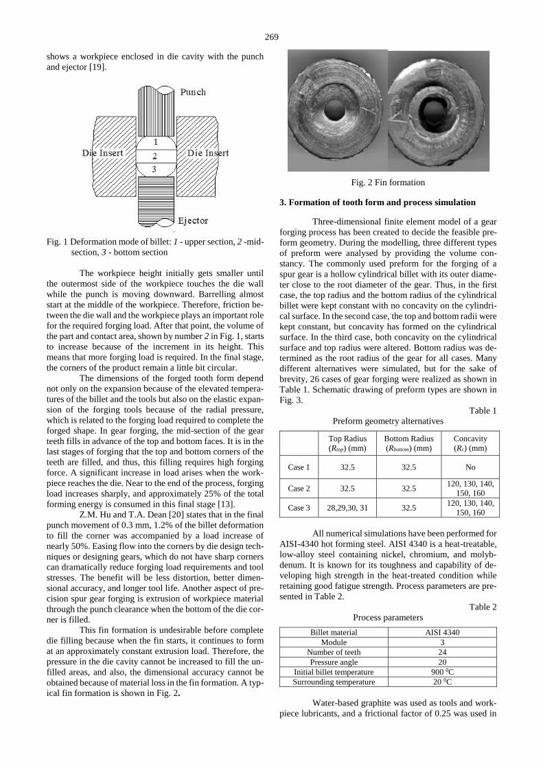
This fin formation is undesirable before complete
die filling because when the fin starts, it continues to form
at an approximately constant extrusion load. Therefore, the
pressure in the die cavity cannot be increased to fill the un-
filled areas, and also, the dimensional accuracy cannot be
obtained because of material loss in the fin formation. A typ-
ical fin formation is shown in Fig. 2.
Fig. 2 Fin formation
3. Formation of tooth form and process simulation
Three-dimensional finite element model of a gear
forging process has been created to decide the feasible pre-
form geometry. During the modelling, three different types
of preform were analysed by providing the volume con-
stancy. The commonly used preform for the forging of a
spur gear is a hollow cylindrical billet with its outer diame-
ter close to the root diameter of the gear. Thus, in the first
case, the top radius and the bottom radius of the cylindrical
billet were kept constant with no concavity on the cylindri-
cal surface. In the second case, the top and bottom radii were
kept constant, but concavity has formed on the cylindrical
surface. In the third case, both concavity on the cylindrical
surface and top radius were altered. Bottom radius was de-
termined as the root radius of the gear for all cases. Many
different alternatives were simulated, but for the sake of
brevity, 26 cases of gear forging were realized as shown in
Table 1. Schematic drawing of preform types are shown in
Fig. 3.
Table 1
Preform geometry alternatives
Top Radius
(Rtop) (mm)
Bottom Radius
(Rbottom) (mm)
Concavity
(Rc) (mm)
Case 1 32.5 32.5 No
Case 2 32.5 32.5 120, 130, 140,
150, 160
Case 3 28,29,30, 31 32.5 120, 130, 140,
150, 160
All numerical simulations have been performed for
AISI-4340 hot forming steel. AISI 4340 is a heat-treatable,
low-alloy steel containing nickel, chromium, and molyb-
denum. It is known for its toughness and capability of de-
veloping high strength in the heat-treated condition while
retaining good fatigue strength. Process parameters are pre-
sented in Table 2.
Table 2
Process parameters
Billet material AISI 4340
Module 3
Number of teeth 24
Pressure angle 20
Initial billet temperature 900 0C
Surrounding temperature 20 0C
Water-based graphite was used as tools and work-
piece lubricants, and a frictional factor of 0.25 was used in
Page 3
270
FEM simulations. Also, heat transfer was accounted by cou-
pled thermomechanical analysis between the tools and
workpiece.
In the analysis, to decrease computer CPU time,
rigid model was assumed for tool material, and only one half
of the gear tooth portion was used because of its symmetry.
Schematic representation of analysis and the CAD drawing
is shown in Fig. 4.
a) Case 1 b) Case 2 c) Case 3
Fig. 3 Preform forge geometries studied in this work
Fig. 4 Die and workpiece representation
4. Results and discussion
Velocity distributions and displacement diagrams
of four different nodes for each case were considered to dis-
cuss the influences of preform geometry. Forging loads
were then carefully examined because excessive load causes
the die failure, whereas less amount of load causes insuffi-
cient corner filling.
4.1. Velocity distributions
Radial flow velocity distributions have vital im-
portance to understand the metal deformation because the
cylindrical gear blank is forced to flow radially. The veloc-
ity distribution, which predicts the lowest work rate, is the
best approximation of the actual velocity distribution. This
principle states that the material should always flow in the
path of least resistance. The lowest work rate principle for
rigid plastic materials can be expressed as shown in Eq. (1).
.
.F
i iv SdV F u DS (1)
The manner in which this equation is solved for the
velocities can be seen in Eq. (2). This variational approach
requires admissible velocities (ui).The velocities are solved
by solving for when the variation in the functional is station-
ary. Because the total solution should be zero, the solution
will tend to maintain a low volumetric strain rate to keep this
integral value low.
. . .
0,F
v v i iv v SdV K dV F u DS (2)
where: is the effective stress, .
is the effective strain
rate, iF represents surface tractions,
.
and .
v are var-
iations in strain rate derived from iu and K is a penalty
constant [21]. The solution for Equations 1 and 2 are the ve-
locities at each node, which are shown as vector arrows in
Fig. 5.
The velocity of the top set of nodes is determined
by the downward speed of the die as well as the friction
model between the billet and the gear die. As it is depicted
in Fig. 6, the boundary conditions of [AB] on the left side of
Page 4
271
the die are specified as a centerline condition, meaning that
the nodes are not allowed to move either right or left. The
bottom nodes also have a symmetry condition, meaning that
they are not allowed to move up or down. These three
boundary conditions allow the mesh to behave as the actual
part.
Fig. 5 Nodal velocity vector
a) Case 1
b) Case 2
c) Case 3
Fig. 6 Radial velocity distributions of nodes P1, P2, P3, P4
for all cases
If the nodal velocities change direction or magni-
tude over very small periods, a small time step size is re-
quired to correctly predict this behavior.
( ) ( ) .
( ) ( ) .
x
y
x t t x t v t
y t t y t v t
(3)
The situation is now addressed to different concave
preforms over a discrete set of points. Figs. 6 a, b and c show
radial velocity (x direction) distributions for cases 1, 2, and
3, respectively. It is evident that the radial flow velocity of
point P2 for case1 is faster than the other points. Because of
the metal flow transfer from top to bottom, point P4 is mov-
ing rather slowly, and thus, there is a velocity difference be-
tween points P1 and P4 during deformation process. This is
clearly showing the reason why filling of die corners is the
main problem. As shown in Figs. 6 b and c, the radial flow
velocity of P1, P2, and P3 for cases 2 and 3 are almost the
same at initial stages. After certain stages, the center part of
the billet is moving faster. Because of the concavity of the
billet, P1, P2, and P3 are touching the die surface almost at
the same time, whereas the bottom corner has not been
reached by the die corner. Compared with case 1, forging
load is relatively reduced, as seen in Table 3. Compared
with the first two cases, Fig. 6 c shows that the points coin-
cide each other and touch the die surface almost at the same
time. Because the contact area and friction are reduced, total
forging load is considerably reduced, and the corners are
completely filled.
4.2. Displacement diagrams
Using a concave circular surface in the die entry
moves the neutral plane toward the part and reduces the
forging load. A good picture of the degree of deformation
that takes place in different regions of a cylinder specimen
upon axial compression may be obtained by drawing an
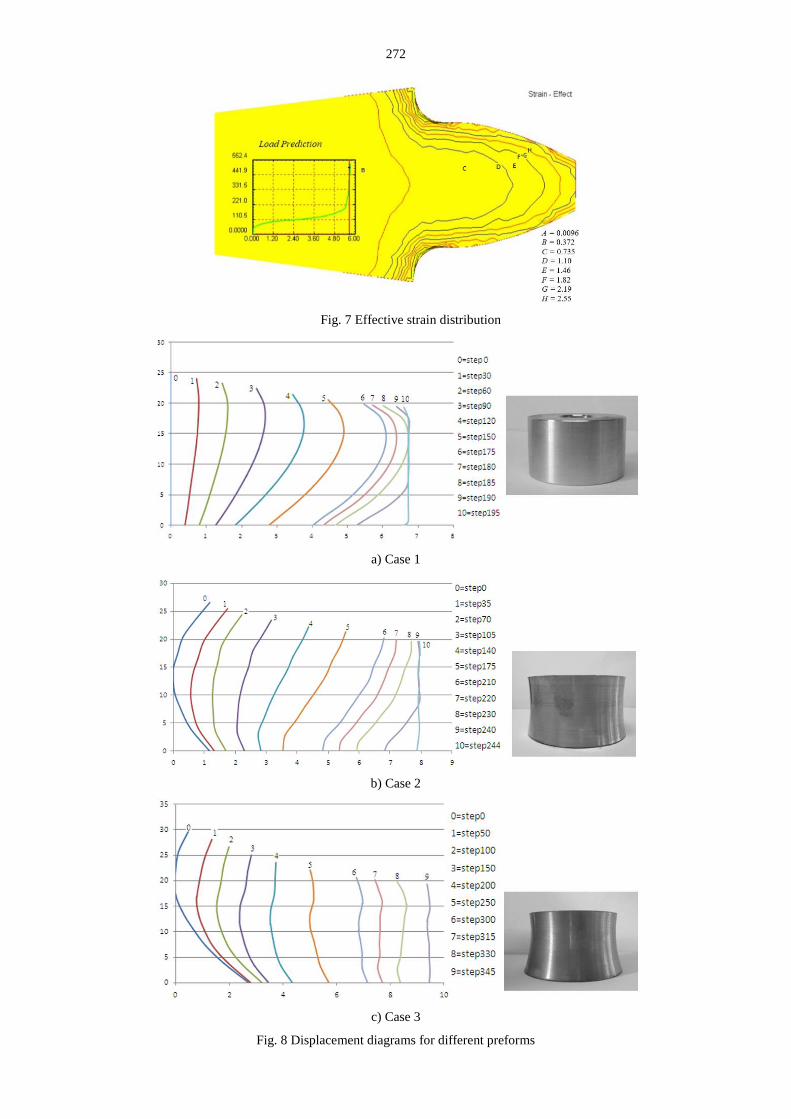
isostrain contour map. The effective strain distribution pre-
sented in Fig. 7 shows that the center part of the billet be-
longs to large deformation area, and this area reaches the
yield limit first. It should be noted that the effective strain is
about 7 times greater in the vicinity of the corners of the
specimen than at the center of its ends. In general, the aver-
age forming load depends on the inherent flow stress of the
billet, the strain pattern determined by the geometry of the
billet and effect of friction at the die material interface.
These conditions can be categorized in terms of the k/µ ra-
tio, where 1 / 3 0.577k for the von Mises criterion,
and µ is the coefficient of friction. According to von Mises
criterion, τ0 is related to the flow stress in compression by
0/ 3 . The following axisymmetric equation [22] for
the pressure distribution at the platen cylinder interface for
which sliding friction occurs over the entire surface is ob-
tained:
2 / ( / 2 ),
h d rPe
(4)
where: P is the normal interfacial pressure, d is the diameter
of the billet, and h is the height of the billet. The analytical
expression for the critical radius rc can be found by equating
the frictional drag µp for sliding friction to that for sticking
friction3
as follows:
Page 5
272
Fig. 7 Effective strain distribution
a) Case 1
b) Case 2
c) Case 3
Fig. 8 Displacement diagrams for different preforms
Page 6
273
.3
p
(5)
By substituting p into Eq. (4) and taking the neutral
logs of both sides:
1
2 2 3c
d hr ln
(6)
This rc value defines the radial distance from the
center to any point on the face of the billet. To realize the
deformation area, nodal displacement of nodes was rec-
orded by point tracking facility of DEFORM 3D. In the fol-
lowing Fig. 8, point tracking is used to show how material
moves and plots of strain distributions at these points.
In the first case, simple hollow cylindrical billet is
forged. Displacement diagram of case 1 is shown step by
step in Fig. 8, a. It is seen that the mid-section of the work-
piece grows faster than the top and bottom corners because
of the frictional force on the top and bottom faces of the
workpiece. Because the metal flow is transferred from top
to bottom along the billet, the top corner is filling first.
Deformation process of the second preform alter-
native is shown in Fig. 8, b. In this alternative, a certain con-
cavity is given to the preform geometry. During gear forg-
ing, the mid-section of the tooth gets contact with the die
surface faster than the top and bottom. The frictional re-
sistance from the die surface acts differently according to
punch movement. During the punch movement, the fric-
tional force opposes the metal flow downward, and the top
region fills more rapidly. Thus, the upper face of the work-
piece is formed prior to the middle and bottom regions. In
the third alternative, because the top and mid surfaces of the
billet are moving faster, the top surface radius was reduced
relative to the bottom radius of the gear (Fig. 8, c). The bot-
tom surface remains at the root diameter of the gear blank.
In this case, the top and bottom corners and the mid-section
of the toothed gear get contact with the die surface in good
accordance. Also, corners are completely filled in a reason-
able step with considerably less amount of forging load.
4.3. Forming load simulations
Load values for different cases of gear forging sim-
ulations are presented in Table 3. It is noticed that there is a
dramatic change in forging load. In case 1, minimum load
to fill the spur gear die cavity is 494.2 tons, whereas in case
3, it is 324.9 tons. This means that the total forging load is
approximately saved by 34% through the use of concave
preform.
Table 3
Forging load results of FEM simulations
R(top) (mm) R(bottom) (mm) R(concavity) (mm) Load (ton)
1 Case 1 32.25 32.25 - 494.2
2 32.25 32.25 120 396.3
3 32.25 32.25 130 383.6
4 Case 2 32.25 32.25 140 393.9
5 32.25 32.25 150 331.3
6 32.25 32.25 160 445.3
7 28 32.25 120 436.5
8 28 32.25 130 402.2
9 28 32.25 140 390.9
10 28 32.25 150 324.9
11 28 32.25 160 448.7
12 29 32.25 120 417.8
13 29 32.25 130 423.7
14 29 32.25 140 439.9
15 29 32.25 150 415.9
16 29 32.25 160 450.4
17 Case 3 30 32.25 120 361.1
18 30 32.25 130 412.9
19 30 32.25 140 433.5
20 30 32.25 150 447.7
21 30 32.25 160 389.9
22 31 32.25 120 425.7
23 31 32.25 130 338.1
24 31 32.25 140 417.4
25 31 32.25 150 434.0
26 31 32.25 160 439.4
Because of symmetry, a portion corresponding to
only one half of the gear teeth was used for analysis. Load
stroke diagrams of these three alternative gear forging cases
are shown in Fig. 9. Forging load to fulfill the die cavity for
cases 2 and 3 is considerably reduced compared with case1.
Page 7
274
Forging loads are carefully examined because ex-
cessive load will cause the die to expand, impairing the ac-
curacy of the forged parts and reducing the die life. On the
other hand, less amount of load will cause the insufficient
corner filling.
Table 4, 5 and 6 show the forming stages of FE
simulation of three different concave preform.
Fig. 9 Load-stroke diagrams
It is very apparent that the tooth formation of con-
cave preforms completely filled the die with less amount of
load. In these tables, PD denotes punch displacement and S
is the percentage of total stroke that is calculated as:
(%) 100,
i f
PDS
H H
(7)
where: Hi and Hf are the initial and final height of the billet,
respectively.
Due to volume constancy of all billets, initial
heights and thus the punch displacement are different. In
Fig. 10 the variation of forging loads with respect to stroke
percentage is shown to compare all three cases independent
from the punch displacement. The analysis and geometric
models were generated using DEFORM 3D. In the early
stages of gear forging, billet behaves as open die forging.
Thus, the material in the middle section flows faster than the
material in the top and bottom regions because of the fric-
tion force on the punch and the counterpart. As it is also
clear from Fig. 10 that the inclination in the forming load up
to 95% of the punch stroke is almost the same, whereas the
main increment in the forming load is recorded at the last
2% of the punch stroke. Thus, the die cavity is completely
filled at the end of the process, leaving no free surfaces at
the corner.
Table 4
Gear tooth simulation for CASE 1
Height 24.34 mm 21.95 mm 21.13 mm 20.18 mm 20.08 mm 20.00 mm
PD 1.31 mm 3.65 mm 4.52 mm 5.47 mm 5.57 mm 5.65 mm
S (%) 25 65 80 95 98 100
Load (ton) 94.92 122.32 143.85 186.42 269.11 494.20
Table 5
Gear tooth simulation for CASE 2
Height 25.49 mm 22.55 mm 21.47 mm 20.36 mm 20.15 mm 20.00 mm
PD 1.83 mm 4.77 mm 5.85 mm 6.96 mm 7.17 mm 7.32 mm
S (%) 25 65 80 95 98 100
Load (ton) 62.1 111 127.7 172.7 209.9 331.3
Page 8
275
Table 6
Gear tooth simulation for CASE 3
Fig. 10 Forging load variation with respect to punch stroke
5. Experimental study
The preform type commonly used in traditional
spur gear forging is to use hollow cylindrical billet with its
external diameter equal to the almost gear tooth root diam-
eter. In this study, contact time between the die and the
workpiece is reduced using concave preform, and therefore,
forging load is considerably reduced. Fig. 11 shows the die
used in the experiment and the forged gear obtained from
concave preform.
Fig. 11 Die and forged gear
Schematic representation of die configuration is
shown in Fig. 12. The right-hand side is the arrangement of
die elements before the deformation, whereas the left side is
after deformation. In this configuration, the punch is shown
as a single unit, and the detail of the punch is not given for
the sake of clarity. The punch forms the top surface of a cav-
ity and is attached to the moving ram of a forging machine.
The ejector is used to remove the product from the die with-
out deforming them and for easy removal of scale and lub-
ricant deposits.
Die insert forms the inner side of the die (die cav-
ity, toothed die). Because die insert is subjected to forging
load, friction load, and temperature, its material must be
chosen so that it resists all required conditions. To increase
the resistance against internal pressure, it is usual to make
an insert shrink fitted into one or more shrink rings. The
compressive stress imposed by the shrink ring has cumula-
tive effect on the bore of the die insert. Therefore, resultant
tensile stress on the bore caused by the forging loads trans-
mitted through the forging part can be substantially reduced.
Fig. 12 Spur gear forging tool design
The preforms were heated to 1000°C in 10 minutes
in order to minimize pre-forging scale formation and decar-
burization. They were taken from the furnace, momentarily
immersed in water to break off scale, quickly placed in die
and forged at 900°C. During forging trials, the 24-teeth gear
with a height of 20 mm and a module of 3 mm is forged.
Forging loads versus stroke acting on the punch were rec-
orded. Fig. 13 shows punch stroke percentage versus form-
ing load. It is seen that there is high correlation between the
experimental results and the FE verification of proposed
concave preform. All forging experiments were carried out
under the same conditions as used for the finite element sim-
ulation.
Height 30.66 mm 24.96 mm 22.83 mm 20.68 mm 20.26 mm 20.00 mm
PD 3.57 mm 9.27 mm 11.4 mm 13.55 mm 13.97 mm 14.23 mm
S(%) 25 65 80 95 98 100
Load(ton) 40.56 91.49 104.7 153.14 176.14 324.9
Page 9
276
Fig. 13 Verification of FE prediction and experimental result
6. Conclusions
The total forging load consist mainly of defor-
mation load and friction load. The frictional force between
the die and the workpiece interface plays an important role
in die filling and total forging load. Cylindrical flat (no con-
cavity) billets are generally used in precision spur gear forg-
ing. The mode of metal flow is very close to open die forg-
ing if cylindrical flat sided (no concavity) billets are used.
Due to barreling effect, mid-section of the billet touches to
the die wall prior to its top and bottom corners. Due to fric-
tion effect and longer contact time between the billet and
thee die corner filling requires very high loads. It is noticed
that final punch movement of 0.26 mm and 2% of the billet
deformation to fill the corner was accompanied by a load
increase of nearly 45%.
This study presented a new biller geometry named
as concave preform to overcome this problem. After various
preform concavities were analyzed, a particular concave ge-
ometry was prepared for the selected spur gear (3 mm made,
24 teeth AISI 4340 steel) forging. The results of FE simula-
tions and experimental studies were shown that the forging
load was reduced 34% and better corner filling by using the
concave pre-form compared to simple cylindrical (no con-
cave) billet.
By the investigation of velocity distributions of the
cylindrical billet, the inhomogeneous distribution of radial
velocity of the billet is the main cause of insufficient corner
filling. It was concluded that the lowest work rate principle
is the best approximation of the actual velocity distribution.
Acknowledgment
The author would like to thank the University of
Gaziantep Scientific Research and Projects unit.
References
1. Eyercioglu, O.; Walton, D.; Dean, T.A. 1997. Com-
parative bending fatigue strength of precision forged
spur gears, Proceedings of IMechE Part-C Journal of
Mechanical Engineering Science 21: 4: 293-299.
https://doi.org/10.1243/0954406971522051.
2. Dean, T.A. 2000. The Net-shape forming of spur gears,
Materials and Design 21: 271-278.
https://doi.org/10.1016/S0261-3069(99)00074-6.
3. Naunit, R.C.; Yohng, J.K. 2001. Near net shape forg-
ing of a crown gear: Some experimental results and anal-
ysis, International Journal of Machine Tools & Manu-
facture 41: 325-346.
https://doi.org/10.1016/S0890-6955(00)00083-3.
4. Qingbin, L.; Shichun, W.; Sheng, S. 1998. Preform de-
sign in axisymmetric forging by a new FEM-UBET
method, Journal of Materials Processing Technology 74:
218-222.
https://doi.org/10.1016/S0924-0136(97)00271-9.
5. Yilmaz, N.F.; Eyercioglu, O. 2009 An integrated com-
puter aided decision support system for die stresses and
dimensional accuracy of precision forging dies, Interna-
tional Journal of Advanced Manufacturing Technology
40: 9-10: 875-886
https://doi.org/10.1007/s00170-008-1402-z.
6. Yilmaz, N.F.; Eyercioglu, O. 2008 Knowledge based
reverse engineering tool for near net shape axisymmetric
forging die design, Mechanika 5: 65-73.
7. Yilmaz, N.F.; Eyercioglu, O. 2003 Application of
UBET in the prediction of forging load for axisymmetric
forging, Int J Adv Manuf Syst 6: 1-11.
8. Eyercioglu, O.; Kutuk, M.A.; Yilmaz, N.F. 2009.
Shrink fit design for precision gear forging dies, Journal
of Materials Processing Technology 209: 2186-2194.
https://doi.org/10.1016/j.jmatprotec.2008.05.016.
9. Jin, J.; Xia, J.; Wang, X.; Hu, G.; Liu, H. 2009. Die
design for cold precision forging of bevel gear based on
finite element method, Journal of Central South Univer-
sity of Technology 16: 546-551.
https://doi.org/10.1007/s11771-009-0091-6.
10. Kiekbusch, T.; Sappok, D.; Sauer, B.; Howard, I. 2011. Calculation of the combined torsional mesh stiff-
ness of spur gears with two- and three-dimensional par-
ametrical FE models, Strojniski vestnik - Journal of Me-
chanical Engineering 57, 11: 810-818.
http://dx.doi.org/10.5545/sv-jme.2010.248.
11. Podrug, S.; Glodez, S.; Jelaska, D. 2011.Numerical
modelling of crack growth in a gear tooth root, Strojniski
vestnik - Journal of Mechanical Engineering 57, 7-8:
579-586.
http://dx.doi.org/10.5545/sv-jme.2009.127.
12. Ohga, K.; Kondo, K.; Jitsunari, T. 1985. Research on
precision die forging utilizing divided flow, Bulletin of
the Japan Society of Mechanical Engineers 28: 2451-
2459.
Page 10
277
https://doi.org/10.1299/jsme1958.28.2451.
13. Arbak, M.; Tekkaya, A.E.; Ozhan, F. 2005. Compar-
ison of various preforms for hot forging of bearing rings,
Journal of Materials Processing Technology 169: 72-82.
https://doi.org/10.1016/j.jmatprotec.2004.11.020.
14. Cai, J.; Dean, T.A.; Hu, M. 2004. Alternative die de-
signs in net-shape forging of gears, Journal of Materials
Processing Technology 150: 48-55.
https://doi.org/10.1016/j.jmatprotec.2004.01.019.
15. Chengliang, H.; Kesheng, W.; Quankun, L. 2007.
Study on new technological scheme for cold forging of
spur gears, Journal of Materials Processing Technology
187-188: 600-603.
https://doi.org/10.1016/j.jmatprotec.2006.11.037.
16. Long, L.; Feng, X.; Tao, J.; Qi, Z.; Sungki, L. 2010.
Characteristic evaluation of friction and wear in the C-N
and TiN coated gear, Int Journal of Precision Engineer-
ing and Manufacturing 11: 107-111.
https://doi.org/10.1007/s12541-010-0013-4.
17. Eyercioglu, O.; Dean, T.A.; Walton, D. 1994.Dimen-
sional accuracy of hot precision forged spur gears, Pro-
ceedings of the 1994 International Gearing Conference,
Newcastle upon Tyne 285-290.
18. Tuncer, C.; Dean, T.A. 1987. Design alternatives for
precision forging hollow parts, International Journal of
Machine Tools and Manufacture 27: 65-76.
https://doi.org/10.1016/S0890-6955(87)80040-8.
19. Vidal-Salle, E.; Boutabba, S.; Cui, Y.; Boyer, J.C. 2008. An improved plastic wave friction model for
rough contact in axisymmetric modelling of bulk form-
ing processes, International Journal of Material Forming
1: 1263-1266.
https://doi.org/10.1007/s12289-008-0132-y.
20. Hu, Z.M.; Dean, T.A. 2000. Some aspects of net shape
forging of gears, Proceedings of the Second Interna-
tional Seminar on Precision Forging 127-132.
21. Kobayashi, S.; Oh, S.I.; Altan, T. 1989. Metalforming
and the finite-element method, 1st ed. Oxford University
Press.
22. Mielnik, E.M. 1991. Metalworking Science and Engi-
neering, 1st ed. McGraw-Hill.
N. F. Yilmaz, O. Eyercioglu
NEAR NET SHAPE SPUR GEAR FORGING USING
CONCAVE PREFORM
S u m m a r y
The objective of this paper is to determine the fea-
sible preform forge geometry for spur gear blank to reduce
the forging load requirement. This paper discusses the ef-
fects of different preform geometries on the forming behav-
ior of precision forged gear wheel geometry. It is identified
that material flow and friction between die and billet are en-
countered as the major problem in precision forging. Radial
flow velocity distributions and displacement diagrams of
preform types in accordance with the forming stages were
put into perspective. The analyzed preforms were evaluated
in terms of forging load versus punch displacement dia-
grams. The effect of concave preforms on the material flow
and the resulting manufacturing quality by finite element
simulation in comparison with practical forging tests were
analyzed to ensure a proper die filling and load require-
ments. Finally, a concave preform is proposed for which the
forming load could be reduced by 34%.
Key words: spur gear, precision forging, preform design,
concave preform.
Received October 23, 2017
Accepted April 18, 2018