NEC Express5800/D120h System Configuration Guide Introduction This document contains product and configuration information that will enable you to configure your system. The guide will ensure fast and proper configuration of your NEC Express5800 server. March 28, 2019 Revision 6.0 NEC Corporation
Transcript
NEC Express5800/D120h
System Configuration Guide
Introduction
This document contains product and configuration information that will enable you to configure your system. The guide will ensure fast and proper configuration of your NEC Express5800 server.
March 28, 2019
Revision 6.0
NEC Corporation
SYSTEM CONFIGURATION GUIDE – NEC Express5800/D120h
NEC Corporation Revision 6.0 – March 2019 2
Contents
MODEL LINEUP .............................................................................................................. 4
1U Server Module Model ................................................................................................................. 4 2U Server Module Model ................................................................................................................. 4
Copyright Notice and Liability Disclaimer ........................................................................................ 44
SYSTEM CONFIGURATION GUIDE – NEC Express5800/D120h
NEC Corporation Revision 6.0 – March 2019 3
REVISION HISTORY ..................................................................................................... 45
SYSTEM CONFIGURATION GUIDE – NEC Express5800/D120h
NEC Corporation Revision 6.0 – March 2019 4
Model Lineup Ideal for high density and performance with just 2U space, D120h offers both 1U server module for density and 2U server module with high performance GPU card. For detail configuration, please contact your sales representative.
1U Server Module Model
2U Server Module Model
Node 1
Node 2
Node 3
Node 4
Node 2Node 4
SYSTEM CONFIGURATION GUIDE – NEC Express5800/D120h
NEC Corporation Revision 6.0 – March 2019 5
Technical Specification
Specification
Server Module (1/2)
Model D120h
1U Server Module 2U Server Module
Part Number N8100-2553F N8100-2554F
Processor Type Intel® Xeon® Processor
Bronze 3104 (1.70 GHz, 6C/6T, 8.25MB)
Bronze 3106 (1.70 GHz, 8C/8T, 11MB)
Silver 4108 (1.80 GHz, 8C/16T, 11MB)
Silver 4110 (2.10 GHz, 8C/16T, 11MB)
Silver 4114 (2.20 GHz, 10C/20T, 13.75MB)
Silver 4116 (2.10 GHz, 12C/24T, 16.50MB)
Gold 5118 (2.30 GHz, 12C/24T, 16.50MB)
Gold 5120 (2.20 GHz, 14C/28T, 19.25MB)
Gold 5122 (3.60 GHz, 4C/8T, 16.50MB)
Gold 6130 (2.10 GHz, 16C/32T, 22MB)
Gold 6132 (2.60 GHz, 14C/28T, 19.25MB)
Gold 6134 (3.20 GHz, 8C/16T, 24.75MB)
Gold 6138 (2GHz, 20C/40T, 27.50MB)
Gold 6140 (2.30 GHz, 18C/36T, 24.75MB)
Gold 6142 (2.60 GHz, 16C/32T, 22MB)
Gold 6152 (2.10 GHz, 22C/44T, 30.25MB)
Platinum 8160 (2.10 GHz, 24C/48T, 33MB)
Platinum 8164 (2GHz, 26C/52T, 35.75MB)
Platinum 8160M (2.10 GHz, 24C/48T, 33MB)
Number of Processors 1 or 2
Chipset Intel® C621 Chipset
Memory Type DDR4-2666 Registered DIMM (8/16/32GB)
DDR4-2666 TSV Registered DIMM (64GB/128GB)
Standard Capacity 0 GB
Maximum Capacity 2TB (16x 128GB) [Platinum 8160M only]
1.5TB (12x 128GB) [Others]
Memory protection ECC, x4/x8 SDDC, DDDC
Internal Storage Drive Cage -
Disk Controller SATA : 6Gb/s, RAID 0/1/5/6/10/50/60 (Optional)
SAS: 12 Gb/s, RAID 0/1/5/6/10/50/60 (Optional)
Expansion Slot Total: 3 slots available
1 PCIe 3.0 x16 (x16 connector)
1 PCIe 3.0 x8 (x8 connector)
1 PCIe 3.0 x16 for a LAN mezzanine card
Total: 4 slots available
1 PCIe 3.0 x16 ( x16 connector)
1 PCIe 3.0 x8 (x8 connector)
1 PCIe 3.0 x16 for a LAN mezzanine card
1 PCIe 3.0 x16 for GPU card
Video Controller (VRAM) Integrated in Server Management Controller (32MB)
Resolution 1920 x 1200 / 16.7M
Interfaces Rear 1x VGA (15-pin mini D-sub), 2x USB3.0, 2x 10GBASE-T LAN connector (RJ-45), 1x 1000BASE-T LAN connector for Management (RJ-45)
Power Consumption Minimum 607 W 984 W
Heat Dissipation Minimum 2,186 kj/h 3,543 kj/h
Dimension (W x D x H)
171.6 × 547.5 × 40.6 mm 6.76 x 21.6 x 1.60 in
171.6 × 547.5 × 81.5 mm 6.76 x 21.6 x 3.21 in
Weight Minimum 3.3 kg 4.2 kg
Maximum 4.2 kg 6.7 kg
Temperature, Relative Humidity (non-condensing)
Operating: 10° to 35°C / 50° to 95°F, 20 to 80%
Non-operating: -10° to 55°C / 14° to 131°F, 20 to 80%
Regulatory and Safety FCC, CE, UL, CB, RoHS, WEEE
Operating Systems Microsoft® Windows Server® 2012 R2 Standard
Microsoft® Windows Server® 2012 R2 Datacenter
Microsoft® Windows Server® 2016 Standard
Microsoft® Windows Server® 2016 Datacenter
SYSTEM CONFIGURATION GUIDE – NEC Express5800/D120h
NEC Corporation Revision 6.0 – March 2019 6
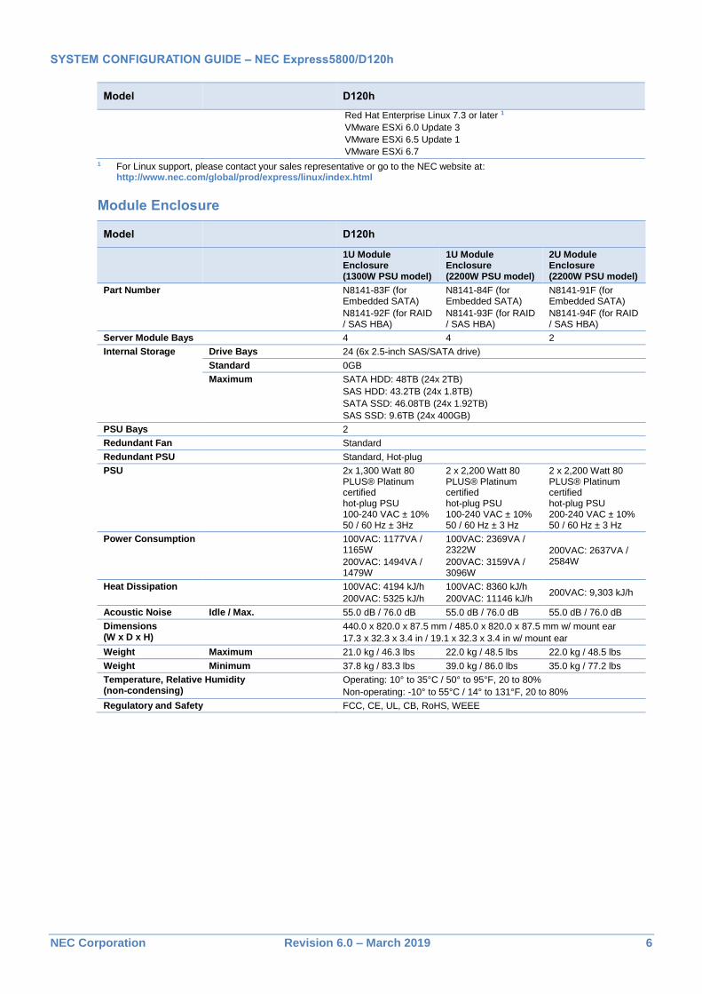
Model D120h
Red Hat Enterprise Linux 7.3 or later 1
VMware ESXi 6.0 Update 3
VMware ESXi 6.5 Update 1
VMware ESXi 6.7
1 For Linux support, please contact your sales representative or go to the NEC website at: http://www.nec.com/global/prod/express/linux/index.html
SYSTEM CONFIGURATION GUIDE – NEC Express5800/D120h
NEC Corporation Revision 6.0 – March 2019 7
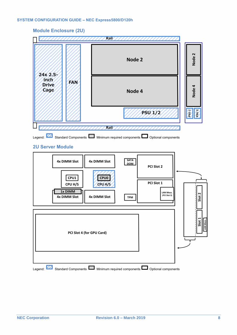
Configuration Diagram Configuration Diagram is the useful tool for configure D120h. This diagram shows three components. One is the standard components, second is the selectable components, and last is the optional components. For example of 1U Module Enclosure, drive cage, fan, rail and PSU is the standard component which has been already installed into 1U Module Enclosure. All you have to do is purchase two nodes (Server Modules) which is the selectable components. In addition, the rest, you can install more two nodes (server modules) as you need.
Module Enclosure (1U)
Legend: Standard Components Minimum required components Optional components
1U Server Module
Legend: Standard Components Minimum required components Optional components
24x 2.5-inchDriveCage
PSU 1/2
FAN
Node 1 (Upper)/
Node 2 (Lower)
Rail
Rail
Node 3 (Upper)/
Node 4 (Lower)
No
de
1N
od
e 3
No
de
2N
od
e 4
PS
U 2
PS
U 1
CPU H/S CPU H/S
4x DIMM Slot
4x DIMM Slot 4x DIMM Slot
4x DIMM Slot
1x DIMM
LAN
Me
zz.
Slo
t2
Slo
t 1
PCI Slot 1
PCI Slot 2
LAN Mezz.(Slot 3)
CPU1 CPU0
SATADOM
TPM
SYSTEM CONFIGURATION GUIDE – NEC Express5800/D120h
NEC Corporation Revision 6.0 – March 2019 8
Module Enclosure (2U)
Legend: Standard Components Minimum required components Optional components
2U Server Module
Legend: Standard Components Minimum required components Optional components
24x 2.5-inchDriveCage
PSU 1/2
FAN
Node 2
Rail
Rail
Node 4
No
de
2N
od
e 4
PS
U 2
PS
U 1
LAN
Me
zz.
Slo
t2
Slo
t1
PCI Slot 4 (for GPU Card)
CPU H/S CPU H/S
4x DIMM Slot
4x DIMM Slot 4x DIMM Slot
4x DIMM Slot
1x DIMM
PCI Slot 1
PCI Slot 2
LAN Mezz.(PCI Slot 3)
CPU1 CPU0
SATADOM
TPM
SYSTEM CONFIGURATION GUIDE – NEC Express5800/D120h
NEC Corporation Revision 6.0 – March 2019 9
Server Configuration
1 Maximum Server Module Configuration See the table below for the maximum server configuration based on processor configuration.
The condition for the maximum server configuration is defined when four servers with the same configuration are installed. For other server configurations, please consult your sales representative.
1.1 Module Enclosure (1U)
1.1.1 2200W PSU Configuration
100VAC Input (with RAID controller, PCI card and LAN mezzanine)
Processor # of processors # of DIMMs
(128GB TSV RDIMM) # of drives
(1.92TB SATA SSD)
Bronze 3104/3106 2CPUs
Up to 5 DIMMs Up to 1 drive
Up to 2 DIMMs Up to 3 drives
Silver 4110/4114/4116
Gold 5122 2CPUs
Up to 4 DIMMs Up to 1 drive
Up to 2 DIMMs Up to 2 drives
Silver 4108 2CPUs
Up to 3 DIMMs Up to 1 drive
Up to 2 DIMMs Up to 2 drives
Gold 5118/5120 2CPUs Up to 3 DIMMs Up to 1 drive
Gold 6130/6138 1CPU
Up to 6 DIMMs Up to 1 drive
Up to 1 DIMM Up to 4 drives
Gold 6132/6134/6140/6142/6152
Platinum 8160/8164/8160M Not supported
NOTE:
Supported configuration depends on the kind of DIMMs, drives.
Table above is just one example of configuration. For details, please contact your sales representative.
Configurations which doesn’t listed above table, please contact your sales representative.
When PSU breaks down, processor may slow down in some configurations. For details, please contact your sales representative.
200VAC Input (with RAID controller, PCI card and LAN mezzanine)
Processor # of processors # of DIMMs
(128GB TSV RDIMM) # of drives
(1.92TB SATA SSD)
Any processors Any configurations
NOTE:
Up to six 128GB TSV RDIMM per processor except Xeon Platinum 8160M.
When PSU breaks down, processor may slow down in some configurations. For details, please contact your sales representative.
1.1.2 1300W PSU Configuration
100VAC Input (with RAID controller, PCI card and LAN mezzanine)
Processor # of processors # of DIMMs
(128GB TSV RDIMM) # of drives
(1.92TB SATA SSD)
Bronze 3104/3106,
Silver 4108/4110/4114/4116,
Gold 5118/5120/5122
Up to 3 server module with configuration limitation.
For details, please contact your sales representative.
Gold 6130/6132/6134/6138/ 6140/6142/6152,
Platinum 8160/8164/8160M
Not supported
SYSTEM CONFIGURATION GUIDE – NEC Express5800/D120h
NEC Corporation Revision 6.0 – March 2019 10
200VAC Input (with RAID controller, PCI card and LAN mezzanine)
Processor # of processors # of DIMMs
(128GB TSV RDIMM) # of drives
(1.92TB SATA SSD)
Bronze 3104/3106,
Silver 4108/4110/4114/4116 1CPU
Up to 6 DIMMs Up to 1 drive
Up to 1 DIMM Up to 4 drives
Gold 5118/5120/5122 1CPU
Up to 4 DIMMs Up to 1 drive
Up to 1 DIMM Up to 2 drives
Gold 6130/6132/6134/6138/
6140/ 6142/6152,
Platinum 8160/8164/8160M
Not supported
NOTE:
Supported configuration depends on the kind of DIMMs, drives.
Table above is just one example of configuration. For details, please contact your sales representative.
Configurations which doesn’t listed above table, please contact your sales representative.
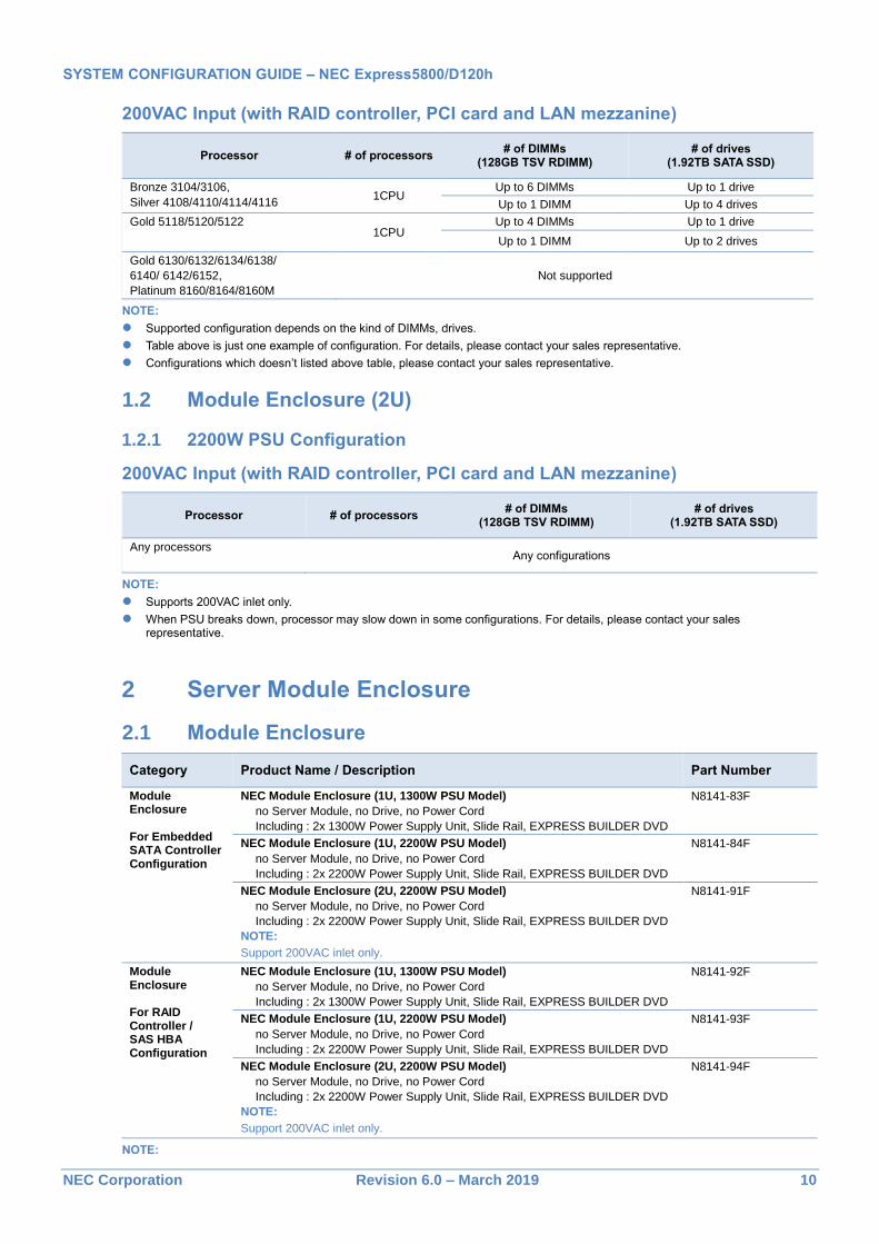
1.2 Module Enclosure (2U)
1.2.1 2200W PSU Configuration
200VAC Input (with RAID controller, PCI card and LAN mezzanine)
Processor # of processors # of DIMMs
(128GB TSV RDIMM) # of drives
(1.92TB SATA SSD)
Any processors Any configurations
NOTE:
Supports 200VAC inlet only.
When PSU breaks down, processor may slow down in some configurations. For details, please contact your sales representative.
2 Server Module Enclosure
2.1 Module Enclosure
Category Product Name / Description Part Number
Module Enclosure For Embedded SATA Controller Configuration
NEC Module Enclosure (1U, 1300W PSU Model)
no Server Module, no Drive, no Power Cord
Including : 2x 1300W Power Supply Unit, Slide Rail, EXPRESS BUILDER DVD
N8141-83F
NEC Module Enclosure (1U, 2200W PSU Model)
no Server Module, no Drive, no Power Cord
Including : 2x 2200W Power Supply Unit, Slide Rail, EXPRESS BUILDER DVD
N8141-84F
NEC Module Enclosure (2U, 2200W PSU Model)
no Server Module, no Drive, no Power Cord
Including : 2x 2200W Power Supply Unit, Slide Rail, EXPRESS BUILDER DVD
NOTE:
Support 200VAC inlet only.
N8141-91F
Module Enclosure For RAID Controller / SAS HBA Configuration
NEC Module Enclosure (1U, 1300W PSU Model)
no Server Module, no Drive, no Power Cord
Including : 2x 1300W Power Supply Unit, Slide Rail, EXPRESS BUILDER DVD
N8141-92F
NEC Module Enclosure (1U, 2200W PSU Model)
no Server Module, no Drive, no Power Cord
Including : 2x 2200W Power Supply Unit, Slide Rail, EXPRESS BUILDER DVD
N8141-93F
NEC Module Enclosure (2U, 2200W PSU Model)
no Server Module, no Drive, no Power Cord
Including : 2x 2200W Power Supply Unit, Slide Rail, EXPRESS BUILDER DVD
NOTE:
Support 200VAC inlet only.
N8141-94F
NOTE:
SYSTEM CONFIGURATION GUIDE – NEC Express5800/D120h
NEC Corporation Revision 6.0 – March 2019 11
Module enclosure must use the appropriate connector to attach the AC power cord to the PSU.
AC cable connector at the PSU side:
1300W PSU Model: IEC320-C13
2200W PSU Model: IEC320-C19
AC cable connector at the outlet side:
In accordance with the local outlet type.
Module enclosure has to be ordered with at least two optional server modules.
Module enclosure P/N depends on internal drive configuration. Module enclosure for embedded SATA controller configuration [N8141-83F/-84F/-91F] supports module enclosure with embedded SATA controller configuration only. Others [N8141-92F/-93F/-94F] supports with RAID controller configuration or SAS HBA configuration only.
When installing to 1U server module enclosure, up to four server modules can be installed.
When installing to 2U server module enclosure, up to two server modules can be installed.
Please connect CMC management LAN on module enclosure to management server or PC for monitoring cooling fan and PSU.
Blank modules [N8141-85] must be installed into vacant module enclosure slots.
Predecessor (ex. Express5800/E120f-M, E120g-M) server module can’t install into server module enclosure.
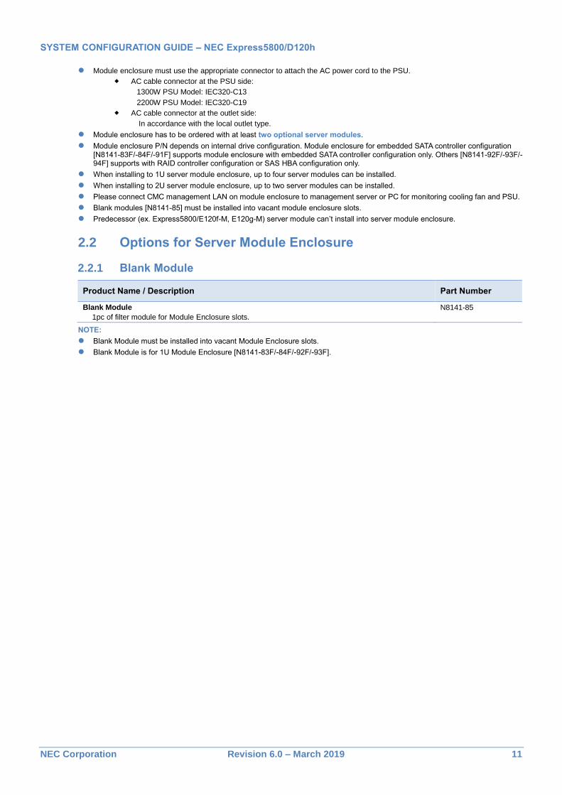
2.2 Options for Server Module Enclosure
2.2.1 Blank Module
Product Name / Description Part Number
Blank Module
1pc of filter module for Module Enclosure slots.
N8141-85
NOTE:
Blank Module must be installed into vacant Module Enclosure slots.
Blank Module is for 1U Module Enclosure [N8141-83F/-84F/-92F/-93F].
SYSTEM CONFIGURATION GUIDE – NEC Express5800/D120h
NEC Corporation Revision 6.0 – March 2019 12
3 Server Module
Product Name / Description Part Number
NEC Express5800/D120h
1U Server Module
No processor, no RAM, no RAID Controller, no LAN mezzanine.
Including:
1st processor (CPU 0) heat sink, Internal SATA Cable
N8100-2553F
NEC Express5800/D120h
2U Server Module
No processor, no RAM, no RAID Controller, no LAN mezzanine
Including:
1st processor (CPU 0) heat sink, SAS Expander, Internal SATA Cable, Power Cord for GPU Card(8Pin)
N8100-2554F
NOTE:
The base model must be ordered with a processor kit and a memory kit.
At least two server modules must be installed in module enclosure to configure D120h.
Note for N8100-2553F, N8100-2554F
1U server modules must be installed in N8141-83F, N8141-84F, N8141-92F or N8141-93F.
2U server modules must be installed in N8141-91F or N8141-94F.
SYSTEM CONFIGURATION GUIDE – NEC Express5800/D120h
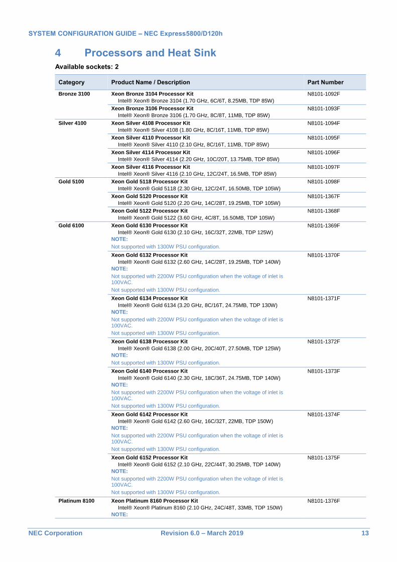
Not supported with 2200W PSU configuration when the voltage of inlet is 100VAC.
Not supported with 1300W PSU configuration.
Support up to 1.5TB/Socket memory. (Others supports up to 768GB/socket memory.)
N8101-1378F
Heat Sink Processor Heat Sink
For 1st Processor
(Standard)
Processor Heat Sink
For 2nd Processor
N8101-1379F
NOTE:
One processor kit from above must be installed.
The processors must be the same to configure dual processor system.
2nd CPU is required when GPU was installed in 2U Server Module.
The procedure is required which takes over fixed IP address in case of adding CPU for Windows Server 2012R2/2016 environment with N8104-149/N8104-170. Please refer “Precautions for using” attached to the product.
The maximum number of logical processors supported by OS
See the table below for the maximum number of logical processors that you can actually use on your system.
Operating Systems Maximum Logical CPUs Supported by Operating Systems
Maximum Logical CPUs
Microsoft Windows Server 2012 R2 Standard
Microsoft Windows Server 2012 R2 Datacenter
640 1 104
Microsoft Windows Server 2016 Standard
Microsoft Windows Server 2016 Datacenter
640 1 104
Red Hat Enterprise Linux 7 384 104
VMware ESXi 6.0 480 104
VMware ESXi 6.5 576 104
VMware ESXi 6.7 768 104
1 The maximum numbers of logical processors when using Hyper-V are below:
- Windows Server 2012 R2: 320
- Windows Server 2016: 512
SYSTEM CONFIGURATION GUIDE – NEC Express5800/D120h
NEC Corporation Revision 6.0 – March 2019 15
5 Memory
Available slots: 8 per processor
Category Product Name / Description Part Number
Registered DIMM
(RDIMM)
8GB DDR4-2666 REG Memory Kit (1x8GB)
1 x 8GB Registered ECC DIMM, DDR4-2666(PC4-2666), Single Rank
N8102-703F
16GB DDR4-2666 REG Memory Kit (1x16GB)
1 x 16GB Registered ECC DIMM, DDR4-2666(PC4-2666), Dual Rank
N8102-704F
32GB DDR4-2666 REG Memory Kit (1x32GB)
1 x 32GB Registered ECC DIMM, DDR4-2666(PC4-2666), Dual Rank
N8102-705F
TSV Registered DIMM (TSV RDIMM)
64GB DDR4-2666 TSV REG Memory Kit (1x64GB)
1 x 64GB TSV Registered ECC DIMM, DDR4-2666(PC4-2666), Quad Rank
NOTE:
The memory kit is make-to-order product.
N8102-706F
128GB DDR4-2666 TSV REG Memory Kit (1x128GB)
1 x 128GB TSV Registered ECC DIMM, DDR4-2666(PC4-2666), Octal Rank
NOTE:
The memory kit is make-to-order product.
N8102-707F
NOTE:
Minimum one memory kit per processor must be installed.
It is recommended to install memory kits in multiples of six DIMMs for six-channel symmetric memory configurations to increase memory transfer speed.
Mix configurations of RDIMM and TSV RDIMM are not supported
The type of TSV RDIMM installed must be identical.
Estimated production lead time for the make-to-order processor kits will be approximately 3 months.
Maximum Memory Capacity
See the table below for the maximum memory capacity in accordance with the type of processor installed.
Processor Type Maximum Memory Capacity per CPU
Xeon ® Platinum 8160M 1TB
All other processors 768GB
Maximum Memory Speed
See the table below for the actual maximum memory transfer speed. DDR4 memory speed depends on the native memory bus speed of the memory controller.
See the table below for the maximum memory size that you can actually use on your system.
Operating Systems Maximum Memory Size Supported by Operating Systems
Maximum Available Memory
Microsoft Windows Server 2012 R2 Standard 1
Microsoft Windows Server 2012 R2 Datacenter 1
4 TB 2 TB
Microsoft Windows Server 2016 Standard 2
Microsoft Windows Server 2016 Datacenter 2
24 TB 2 TB
Red Hat Enterprise Linux 7.3 or later 12 TB 2 TB
VMware ESXi 6.0 3 6 TB 2 TB
SYSTEM CONFIGURATION GUIDE – NEC Express5800/D120h
NEC Corporation Revision 6.0 – March 2019 16
VMware ESXi 6.5 4 12 TB 2 TB
VMware ESXi 6.7 4 16 TB 2 TB
1 Hyper-V in Windows Server 2012 R2
- Maximum memory that apply to each Hyper-V: 4 TB
- Maximum memory that apply to each virtual machine: 1 TB 2 Hyper-V in Windows Server 2016:
- Maximum memory that apply to each Hyper-V: 24 TB
- Maximum memory that apply to each virtual machine: 12 TB 3 Up to 4 TB of the main memory is available to each virtual machine. 4 Up to 6128 GB of the main memory is available to each virtual machine.
SYSTEM CONFIGURATION GUIDE – NEC Express5800/D120h
NEC Corporation Revision 6.0 – March 2019 17
6 Internal Storage
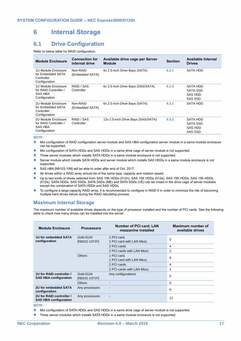
6.1 Drive Configuration
Refer to below table for RAID configuration.
Module Enclosure Connection for internal drive
Available drive cage per Server Module
Section Available Internal Drives
1U Module Enclosure for Embedded SATA Controller Configuration
Non-RAID
(Embedded SATA)
6x 2.5-inch Drive Bays (SATA) 6.2.1 SATA HDD
1U Module Enclosure for RAID Controller / SAS HBA Configuration
RAID / SAS Controller
6x 2.5-inch Drive Bays (SAS/SATA) 6.2.2 SATA HDD
SATA SSD
SAS HDD
SAS SSD
2U Module Enclosure for Embedded SATA Controller Configuration
Non-RAID
(Embedded SATA)
6x 2.5-inch Drive Bays (SATA) 6.3.1 SATA HDD
2U Module Enclosure for RAID Controller / SAS HBA Configuration
RAID / SAS Controller
12x 2.5-inch Drive Bays (SAS/SATA) 6.3.2 SATA HDD
SATA SSD
SAS HDD
SAS SSD
NOTE:
Mix configuration of RAID configuration server module and SAS HBA configuration server module in a same module enclosure can be supported.
Mix configuration of SATA HDDs and SAS HDDs in a same drive cage of server module is not supported.
Three server modules which installs SATA HDDs in a same module enclosure is not supported.
Server module which installs SATA HDDs and server module which installs SAS HDDs in a same module enclosure is not supported.
SAS HBA [N8103-199] will be able to order after end of Oct, 2017.
All drives within a RAID array should be of the same type, capacity and rotation speed.
Up to two kinds of drives selected from SAS 10K HDDs (512n), SAS 10K HDDs (512e), SAS 15K HDDs, SAS 15K HDDs (512e), SATA HDDs, SAS SSDs, SATA SSDs (ME) and SATA SSDs (VE) can be mixed in the drive cage of server modules except the combination of SATA HDDs and SAS HDDs.
To configure a large-capacity RAID array, it is recommended to configure in RAID 6 in order to minimize the risk of becoming multiple hard drives failure during the RAID rebuilding process.
Maximum Internal Storage
The maximum number of available drives depends on the type of processor installed and the number of PCI cards. See the following table to check how many drives can be installed into the server.
Module Enclosure Processors Number of PCI card, LAN
mezzanine installed Maximum number of
available drives
1U for embedded SATA configuration
Gold 6134
[N8101-1371F]
1 PCI card,
1 PCI card with LAN Mezz. 5
2 PCI cards 4
2 PCI cards with LAN Mezz. 2
Others 1 PCI card,
1 PCI card with LAN Mezz. 6
2 PCI cards 4
2 PCI cards with LAN Mezz. 2
1U for RAID controller / SAS HBA configuration
Gold 6134
[N8101-1371F]
Any configurations 5
Others - 6
2U for embedded SATA configuration
Any processors - 6
2U for RAID controller / SAS HBA configuration
Any processors - 12
NOTE:
Mix configuration of SATA HDDs and SAS HDDs in a same drive cage of server module is not supported.
Three server modules which installs SATA HDDs in a same module enclosure is not supported.
SYSTEM CONFIGURATION GUIDE – NEC Express5800/D120h
NEC Corporation Revision 6.0 – March 2019 18
Server module which installs SATA HDDs and server module which installs SAS HDDs in a same module enclosure is not supported.
Up to two kinds of drives selected from SAS 10K HDDs (512n), SAS 10K HDDs (512e), SAS 15K HDDs, SAS 15K HDDs (512e), SATA HDDs, SAS SSDs, SATA SSDs (ME) and SATA SSDs (VE) can be mixed in the drive cage of server modules except the combination of SATA HDDs and SAS HDDs.
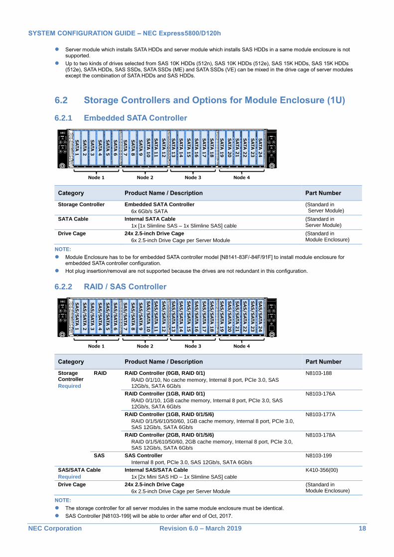
6.2 Storage Controllers and Options for Module Enclosure (1U)
6.2.1 Embedded SATA Controller
Category Product Name / Description Part Number
Storage Controller Embedded SATA Controller
6x 6Gb/s SATA
(Standard in Server Module)
SATA Cable Internal SATA Cable
1x [1x Slimline SAS – 1x Slimline SAS] cable
(Standard in Server Module)
Drive Cage 24x 2.5-inch Drive Cage
6x 2.5-inch Drive Cage per Server Module
(Standard in Module Enclosure)
NOTE:
Module Enclosure has to be for embedded SATA controller model [N8141-83F/-84F/91F] to install module enclosure for embedded SATA controller configuration.
Hot plug insertion/removal are not supported because the drives are not redundant in this configuration.
6.2.2 RAID / SAS Controller
Category Product Name / Description Part Number
Storage Controller
Required
RAID RAID Controller (0GB, RAID 0/1)
RAID 0/1/10, No cache memory, Internal 8 port, PCIe 3.0, SAS 12Gb/s, SATA 6Gb/s
N8103-188
RAID Controller (1GB, RAID 0/1)
RAID 0/1/10, 1GB cache memory, Internal 8 port, PCIe 3.0, SAS 12Gb/s, SATA 6Gb/s
N8103-176A
RAID Controller (1GB, RAID 0/1/5/6)
RAID 0/1/5/6/10/50/60, 1GB cache memory, Internal 8 port, PCIe 3.0, SAS 12Gb/s, SATA 6Gb/s
N8103-177A
RAID Controller (2GB, RAID 0/1/5/6)
RAID 0/1/5/610/50/60, 2GB cache memory, Internal 8 port, PCIe 3.0, SAS 12Gb/s, SATA 6Gb/s
N8103-178A
SAS SAS Controller
Internal 8 port, PCIe 3.0, SAS 12Gb/s, SATA 6Gb/s
N8103-199
SAS/SATA Cable
Required
Internal SAS/SATA Cable
1x [2x Mini SAS HD – 1x Slimline SAS] cable
K410-356(00)
Drive Cage 24x 2.5-inch Drive Cage
6x 2.5-inch Drive Cage per Server Module
(Standard in Module Enclosure)
NOTE:
The storage controller for all server modules in the same module enclosure must be identical.
SAS Controller [N8103-199] will be able to order after end of Oct, 2017.
SATA
1
SATA
2
SATA
3
SATA
4
SATA
5
SATA
6
SATA
7
SATA
8
SATA
9
SATA
10
SATA
11
SATA
12
SATA
13
SATA
14
SATA
15
SATA
16
SATA
17
SATA
18
SATA
19
SATA
20
SATA
21
SATA
22
SATA
23
SATA
24
Node 1 Node 2 Node 3 Node 4
SA
S/S
ATA
1
SA
S/S
ATA
2
SA
S/S
ATA
3
SA
S/S
ATA
4
SA
S/S
ATA
5
SA
S/S
ATA
6
SA
S/S
ATA
7
SA
S/S
ATA
8
SA
S/S
ATA
9
SA
S/S
ATA
10
SA
S/S
ATA
11
SA
S/S
ATA
12
SA
S/S
ATA
13
SA
S/S
ATA
14
SA
S/S
ATA
15
SA
S/S
ATA
16
SA
S/S
ATA
17
SA
S/S
ATA
18
SA
S/S
ATA
19
SA
S/S
ATA
20
SA
S/S
ATA
21
SA
S/S
ATA
22
SA
S/S
ATA
23
SA
S/S
ATA
24
Node 1 Node 2 Node 3 Node 4
SYSTEM CONFIGURATION GUIDE – NEC Express5800/D120h
NEC Corporation Revision 6.0 – March 2019 19
Module Enclosure has to be for RAID controller/SAS HBA model [N8141-94F] to install module enclosure for RAID or SAS Controller configuration.
SAS Controller [N8103-199] doesn’t support booting to disks which connected to SAS Controller. Please use with VMware ESXi support kit (SATA DOM) [N8106-012] for booting.
D120h doesn’t support mixing configuration with disks connected to Embedded SATA and with SAS Controller [N8103-199].
We will release "lifespan monitoring tool for SAS HBA" to monitor the lifespan of SSD after Jan, 2018.
6.3 Storage Controllers and Options for Module Enclosure (2U)
6.3.1 Embedded SATA Controller
Category Product Name / Description Part Number
Storage Controller Embedded SATA Controller
6x 6Gb/s SATA
(Standard in Server Module)
SATA Cable Internal SATA Cable
1x [1x Slimline SAS – 1x Slimline SAS] cable
(Standard in Server Module)
Drive Cage 24x 2.5-inch Drive Cage
6x 2.5-inch Drive Cage per Server Module
(Standard in Module Enclosure)
NOTE:
Module Enclosure has to be for embedded SATA controller model [N8141-83F/-84F/91F] to install module enclosure for embedded SATA controller configuration.
Hot plug insertion/removal are not supported because the drives are not redundant in this configuration.
6.3.2 RAID / SAS Controller in Module Enclosure (2U)
Category Product Name / Description Part Number
Storage Controller
Require
d
RAID RAID Controller (0GB, RAID 0/1)
RAID 0/1/10, No cache memory, Internal 8 port, PCIe 3.0, SAS 12Gb/s, SATA 6Gb/s
N8103-188
RAID Controller (1GB, RAID 0/1)
RAID 0/1/10, 1GB cache memory, Internal 8 port, PCIe 3.0, SAS 12Gb/s, SATA 6Gb/s
N8103-176A
RAID Controller (1GB, RAID 0/1/5/6)
RAID 0/1/5/6/10/50/60, 1GB cache memory, Internal 8 port, PCIe 3.0, SAS 12Gb/s, SATA 6Gb/s
N8103-177A
RAID Controller (2GB, RAID 0/1/5/6)
RAID 0/1/5/610/50/60, 2GB cache memory, Internal 8 port, PCIe 3.0, SAS 12Gb/s, SATA 6Gb/s
N8103-178A
SAS SAS Controller
Internal 8 port, PCIe 3.0, SAS 12Gb/s, SATA 6Gb/s
N8103-199
SAS Expander SAS Expander
SAS 12Gb/s, SATA 6Gb/s
(Standard in Server Module)
SAS/SATA Cable
Required
Internal SAS/SATA Cable
1x [2x Mini SAS HD – 1x Slimline SAS] cable, 1x [1x Slimline SAS – 1x Slimline SAS] cable
K410-357(00)
SATA
7
SATA
8
SATA
9
SATA
10
SATA
11
SATA
12
N/A
SATA
19
SATA
20
SATA
21
SATA
22
SATA
23
SATA
24
Node 2 Node 4
N/A
SA
S/S
ATA
1
SA
S/S
ATA
2
SA
S/S
ATA
3
SA
S/S
ATA
4
SA
S/S
ATA
5
SA
S/S
ATA
6
SA
S/S
ATA
7
SA
S/S
ATA
8
SA
S/S
ATA
9
SA
S/S
ATA
10
SA
S/S
ATA
11
SA
S/S
ATA
12
SA
S/S
ATA
13
SA
S/S
ATA
14
SA
S/S
ATA
15
SA
S/S
ATA
16
SA
S/S
ATA
17
SA
S/S
ATA
18
SA
S/S
ATA
19
SA
S/S
ATA
20
SA
S/S
ATA
21
SA
S/S
ATA
22
SA
S/S
ATA
23
SA
S/S
ATA
24
Node 2 Node 4
SYSTEM CONFIGURATION GUIDE – NEC Express5800/D120h
NEC Corporation Revision 6.0 – March 2019 20
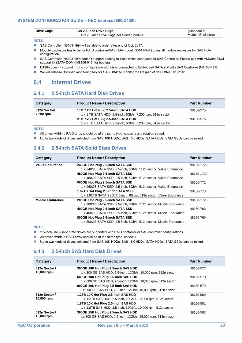
Drive Cage 24x 2.5-inch Drive Cage
12x 2.5-inch Drive Cage per Server Module
(Standard in Module Enclosure)
NOTE:
SAS Controller [N8103-199] will be able to order after end of Oct, 2017.
Module Enclosure has to be for RAID controller/SAS HBA model [N8141-94F] to install module enclosure for SAS HBA configuration.
SAS Controller [N8103-199] doesn’t support booting to disks which connected to SAS Controller. Please use with VMware ESXi support kit (SATA DOM) [N8106-012] for booting.
D120h doesn’t support mixing configuration with disks connected to Embedded SATA and with SAS Controller [N8103-199].
We will release "lifespan monitoring tool for SAS HBA" to monitor the lifespan of SSD after Jan, 2018.
6.4 Internal Drives
6.4.1 2.5-inch SATA Hard Disk Drives
Category Product Name / Description Part Number
512n Sector/ 7,200 rpm
1TB 7.2K Hot Plug 2.5-inch SATA HDD
1 x 1 TB SATA HDD, 2.5-inch, 6Gb/s, 7,200 rpm, 512n sector
N8150-575
2TB 7.2K Hot Plug 2.5-inch SATA HDD
1 x 2 TB SATA HDD, 2.5-inch, 6Gb/s, 7,200 rpm, 512n sector
N8150-576
NOTE:
All drives within a RAID array should be of the same type, capacity and rotation speed.
Up to two kinds of drives selected from SAS 10K HDDs, SAS 15K HDDs, SATA HDDs, SATA SSDs can be mixed.
6.4.2 2.5-inch SATA Solid State Drives
Category Product Name / Description Part Number
Value Endurance 240GB Hot Plug 2.5-inch SATA SSD
1 x 240GB SATA SSD, 2.5-inch, 6Gb/s, 512n sector, Value Endurance
N8150-1728
480GB Hot Plug 2.5-inch SATA SSD
1 x 480GB SATA SSD, 2.5-inch, 6Gb/s, 512n sector, Value Endurance
N8150-1729
960GB Hot Plug 2.5-inch SATA SSD
1 x 960GB SATA SSD, 2.5-inch, 6Gb/s, 512n sector, Value Endurance
N8150-772
1.92TB Hot Plug 2.5-inch SATA SSD
1 x 1.92TB SATA SSD, 2.5-inch, 6Gb/s, 512n sector, Value Endurance
N8150-773
Middle Endurance 200GB Hot Plug 2.5-inch SATA SSD
1 x 200GB SATA SSD, 2.5-inch, 6Gb/s, 512n sector, Middle Endurance
N8150-1725
400GB Hot Plug 2.5-inch SATA SSD
1 x 400GB SATA SSD, 2.5-inch, 6Gb/s, 512n sector, Middle Endurance
N8150-768
800GB Hot Plug 2.5-inch SATA SSD
1 x 800GB SATA SSD, 2.5-inch, 6Gb/s, 512n sector, Middle Endurance
N8150-769
NOTE:
2.5-inch SATA solid state drives are supported with RAID controller or SAS controller configurations.
All drives within a RAID array should be of the same type, capacity.
Up to two kinds of drives selected from SAS 10K HDDs, SAS 15K HDDs, SATA HDDs, SATA SSDs can be mixed.
6.4.3 2.5-inch SAS Hard Disk Drives
Category Product Name / Description Part Number
512n Sector / 10,000 rpm
300GB 10K Hot Plug 2.5-inch SAS HDD
1 x 300 GB SAS HDD, 2.5-inch, 12Gb/s, 10,000 rpm, 512n sector
N8150-577
600GB 10K Hot Plug 2.5-inch SAS HDD
1 x 600 GB SAS HDD, 2.5-inch, 12Gb/s, 10,000 rpm, 512n sector
512e sector drives are not available for VMware ESXi 6.0 system.
All drives within a RAID array should be of the same type, capacity and rotation speed.
Up to two kinds of drives selected from SAS 10K HDDs, SAS 15K HDDs, SATA HDDs, SATA SSDs can be mixed.
To configure a large-capacity RAID array, it is recommended to configure in RAID 6 or RAID 60 in order to minimize the risk of becoming multiple hard drives failure during the RAID rebuilding process.
6.4.4 2.5-inch SAS Solid State Drives
Category Product Name / Description Part Number
Middle Endurance 400GB Hot Plug 2.5-inch SAS SSD
1 x 400GB SAS SSD, 2.5-inch, 12Gb/s, 512n sector, Middle Endurance
N8150-766
NOTE:
Up to two kinds of drives selected from SAS 10K HDDs, SAS 15K HDDs, SATA HDDs, SATA SSDs can be mixed.
7 Optical Drive
Category Product Name / Description Part Number
External External DVD Dual Drive
Slim DVD Dual drive, USB bus powered, not including writing software, Cable length: 60cm DVD read speed: 8x (DVD-ROM / -R / -RW / -R DL / +R / +RW / +R DL) CD read speed: 24x (CD-ROM / -R / -RW)
N8160-101F
NOTE:
Optical disk drive is required for OS Installation and system maintenance.
8 Flash FDD Choose the Flash FDD if you need to prepare an alternative device for a floppy drive.
Product Name / Description Part Number
Flash FDD
USB flash emulating USB floppy disk, Native capacity 1.44 MB
N8160-96
NOTE:
Up to one drive can be connected.
Not supported when VMware is running on the server.
SYSTEM CONFIGURATION GUIDE – NEC Express5800/D120h
NEC Corporation Revision 6.0 – March 2019 22
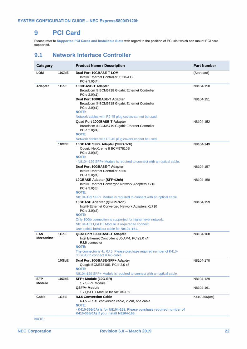
9 PCI Card Please refer to Supported PCI Cards and Installable Slots with regard to the position of PCI slot which can mount PCI card supported.
9.1 Network Interface Controller
Category Product Name / Description Part Number
LOM 10GbE Dual Port 10GBASE-T LOM
Intel® Ethernet Controller X550-AT2
PCIe 3.0(x4)
(Standard)
Adapter 1GbE 1000BASE-T Adapter
Broadcom ® BCM5718 Gigabit Ethernet Controller
PCIe 2.0(x1)
N8104-150
Dual Port 1000BASE-T Adapter
Broadcom ® BCM5718 Gigabit Ethernet Controller
PCIe 2.0(x1)
NOTE:
Network cables with RJ-45 plug covers cannot be used.
N8104-151
Quad Port 1000BASE-T Adapter
Broadcom ® BCM5719 Gigabit Ethernet Controller
PCIe 2.0(x4)
NOTE:
Network cables with RJ-45 plug covers cannot be used.
N8104-152
10GbE 10GBASE SFP+ Adapter (SFP+/2ch)
QLogic NetXtreme II BCM57810S
PCIe 2.0(x8)
NOTE:
- N8104-129 SFP+ Module is required to connect with an optical cable.
N8104-149
Dual Port 10GBASE-T Adapter
Intel® Ethernet Controller X550
PCIe 3.0(x4)
N8104-157
10GBASE Adapter (SFP+/2ch)
Intel® Ethernet Converged Network Adapters X710
PCIe 3.0(x8)
NOTE:
N8104-129 SFP+ Module is required to connect with an optical cable.
N8104-158
10GBASE Adapter (QSFP+/4ch)
Intel® Ethernet Converged Network Adapters XL710
PCIe 3.0(x8)
NOTE:
Only 10Gb connection is supported for higher level network.
N8104-161 QSFP+ Module is required to connect
Use optical breakout cable for N8104-161.
N8104-159
LAN Mezzanine
1GbE Quad Port 1000BASE-T Adapter
Intel Ethernet Controller i350-AM4, PCIe2.0 x4
RJ.5 connector
NOTE:
The connector is 4x RJ.5. Please purchase required number of K410-366(0A) to connect RJ45 cable.
N8104-168
10GbE Dual Port 10GBASE-SFP+ Adapter
QLogic BCM57810S, PCIe 2.0 x8
NOTE:
N8104-129 SFP+ Module is required to connect with an optical cable.
N8104-170
SFP
Module
10GbE SFP+ Module (10G-SR)
1 x SFP+ Module
N8104-129
QSFP+ Module
1 x QSFP+ Module for N8104-159
N8104-161
Cable 1GbE RJ.5 Conversion Cable
RJ.5 – RJ45 conversion cable, 25cm, one cable
NOTE:
- K410-366(0A) is for N8104-168. Please purchase required number of K410-366(0A) if you install N8104-168.
K410-366(0A)
NOTE:
SYSTEM CONFIGURATION GUIDE – NEC Express5800/D120h
NEC Corporation Revision 6.0 – March 2019 23
Network performance depends on the application running on the system and the memory bandwidth. Installing more than six ports of 10G LAN (including on-board 2-port LAN) may degrade network performance. If network throughput is important, we recommend that you evaluate the performance with your systems in advance.
The NIC cards must be installed under the maximum configuration limits for networking when running with VMware systems. For more detail, see the Networking Maximum in the Configuration Maximums document for VMware.
- For VMware ESXi 6.0: https://www.vmware.com/pdf/vsphere6/r60/vsphere-60-configuration-maximums.pdf
- For VMware ESXi 6.5: https://www.vmware.com/pdf/vsphere6/r65/vsphere-65-configuration-maximums.pdf
NIC Teaming feature – NIC Teaming and bonding features
See the table below for supported network interfaces and OS combinations.
Network Interface Team Operating Systems
10GBASE-T LOM
10GBASE-T NIC
N8104-157
Up to four ports per one team Windows Server 2016
Windows Server 2012 R2
Red hat Enterprise Linux 7.3 or later
VMware ESXi 6.0 Update3
VMware ESXi 6.5 Update1
VMware ESXi 6.7
1000BASE-T NIC
N8104-150/-151 and -152
Up to four ports per one team Windows Server 2016
Windows Server 2012 R2
Red hat Enterprise Linux 7.3 or later
VMware ESXi 6.0 Update3
VMware ESXi 6.5 Update1
VMware ESXi 6.7
1000BASE-T NIC
N8104-168
Up to four ports per one team Windows Server 2016
Windows Server 2012 R2
Red hat Enterprise Linux 7.3 or later
VMware ESXi 6.0 Update3
VMware ESXi 6.5 Update1
VMware ESXi 6.7
10GBASE SFP+ NIC
N8104-149 and -170
Up to four ports per one team Windows Server 2016
Windows Server 2012 R2
Red hat Enterprise Linux 7.3 or later
VMware ESXi 6.0 Update3
VMware ESXi 6.5 Update1
VMware ESXi 6.7
10GBASE SFP+ NIC
N8104-158
Up to four ports per one team Windows Server 2016
Windows Server 2012 R2
Red hat Enterprise Linux 7.3 or later
VMware ESXi 6.0 Update3
VMware ESXi 6.5 Update1
VMware ESXi 6.7
10GBASE SFP+ NIC
N8104-159
Up to four ports per one team Red hat Enterprise Linux 7.3 or later
NOTE:
NIC Teaming feature is not supported on iSCSI interfaces.
The network interfaces for each NIC teaming must be the same.
When 10GbE and 1GbE NIC teams are mixed, the maximum number of teams is up to five per one system.
Using iSCSI
See the table below for supported network interfaces and OS combinations.
Category Network Interface Operating Systems
1GbE N8104-150/-151/-152/-168 Windows Server 2012 R2, Windows Server 2016,
Red hat Enterprise Linux 7.3 or later / VMware ESXi 6.0 Update3 / VMware ESXi 6.5 Update1 /
VMware ESXi 6.7
10GbE On-board LAN Interface
N8104-157/-158/-149/-170
Windows Server 2012 R2, Windows Server 2016,
Red hat Enterprise Linux 7.3 or later / VMware ESXi 6.0 Update3 / VMware ESXi 6.5 Update1 /
VMware ESXi 6.7
N8104-159 Red hat Enterprise Linux 7.3 or later
NOTE:
NIC Teaming feature is not supported on iSCSI interfaces.
SYSTEM CONFIGURATION GUIDE – NEC Express5800/D120h
NEC Corporation Revision 6.0 – March 2019 24
9.2 External Storage Controller
9.2.1 Fibre Channel / SAS Controller
Category Product Name / Description Part Number
Fibre Channel Fibre Channel Controller (1ch)
QLogic, QLE2690
16Gb/s, Optical, PCIe 3.0 x8
N8190-161
Fibre Channel Controller (2ch)
QLogic, QLE2692
16Gb/s, Optical, PCIe 3.0 x8
N8190-162
SAS SAS Controller
LSI SAS9300-8e Host Bus Adapter
12Gb/s SAS, ext. 8(SFF-8644 x2), PCIe 3.0 x8
N8103-184
9.3 Serial Port Adapter
Product Name / Description Part Number
Serial Port Adapter
Serial port Connector, Up to one Serial Port Adapter can be installed
N8117-01A
SYSTEM CONFIGURATION GUIDE – NEC Express5800/D120h
NEC Corporation Revision 6.0 – March 2019 25
10 Other Add-in Components
10.1 Trusted Platform Module Kit
Product Name / Description Part Number
Trusted Platform Module Kit
TPM 2.0 module
N8115-31
NOTE:
The kit is not available in China.
The kit is not removable after attachment.
The kit supports only with Windows operating system configured with UEFI boot mode.
"Security Device Support" in BIOS setup menu must be activated prior to use of this product.
To use Windows BitLocker drive encryption, be sure to keep the "recovery password" of BitLocker function. The recovery password is required to restore data for hardware replacement during a system error.
10.2 USB Memory Kit
Product Name / Description Part Number
VMware ESXi support kit
16GB SATA DOM, SLC, Support for VMware ESXi 6.0, 6.5. N8106-012
NOTE:
VMware ESXi support kit doesn't support with Embedded SATA configuration. If you install VMware ESXi support kit, you should configure with RAID controller or SAS HBA.
The kit does not include VMware ESXi installation media and license.
SYSTEM CONFIGURATION GUIDE – NEC Express5800/D120h
NEC Corporation Revision 6.0 – March 2019 26
11 Add-on Components
11.1 17-inch LCD Console Drawer
Category Product Name / Description Part Number
Drawer
w/ KVM
Drawer
17-inch LCD Console Drawer (8port)
17-inch LCD, US 83-keys Keyboard, Optical mouse, 8 port KVM switch, 1U height
N8143-106F
Cable Switch Unit Connection Cable Set (USB, 1.8m)
1.8 m, 1 x 15-pin mini D-sub to 1 x 15-pin mini D-sub / 1 x 4-pin USB A
K410-118(1A)
Switch Unit Connection Cable Set (USB, 3m)
3 m, 1 x 15-pin mini D-sub to 1 x 15-pin mini D-sub / 1 x 4-pin USB A
K410-118(03)
Switch Unit Connection Cable Set (USB, 5m)
5 m, 1 x 15-pin mini D-sub to 1 x 15-pin mini D-sub / 1 x 4-pin USB A
K410-118(05)
Drawer
w/o KVM
Drawer 17inch LCD Console Unit 1U
17-inch LCD, US 83-keys Keyboard, Optical mouse, 1U height, 4-pin USB B to 4-pin USB A cable 2 m, PS/2 Y-splitter cable 2m, 15-pin mini D-sub VGA cable 2 m
N8143-105F
17inch LCD Console Drawer (1port)
17-inch LCD, US 103-keys Keyboard with 10-key, Touch pad with 3-button, 1U height, 4-pin USB B to 4-pin USB A cable 1.8 m, Two PS/2 cable 1.8 m, 15-pin mini D-sub VGA cable 1.8 m
N8143-108F
17.3inch LCD Console Drawer (1port)
17.3-inch wide Full HD LCD, US 103-keys Keyboard with 10-key, Touch pad with 2-button, 1U height, 4-pin USB B to 4-pin USB A cable 1.8 m, 15-pin mini D-sub VGA cable 1.8 m, DVI-D cable 1.8m
N8143-122F
Keypad Keyboard Unit (JP)
JP 108-keys Keyboard with 10-key for N8143-108F 17inch LCD Console Drawer (1port)
N8143-109
Keyboard Unit (UK)
UK 104-keys Keyboard with 10-key, for N8143-108F 17inch LCD Console Drawer (1port)
N8143-111
NOTE:
One Switch Unit Connection Cable Set is required to connect one server.
11.2 KVM Switch
Category Product Name / Description Part Number
KVM Switch Server Switch Unit (8 server)
1U USB 8 port KVM switch
N8191-14F
Cable KVM Switch Unit Connection Cable Set (USB,1.8m)
1.8 m, 1 x 15-pin mini D-sub to 1 x 15-pin mini D-sub / 1 x 4-pin USB A
K410-118(1A)
Switch Unit Connection Cable Set (USB,3m)
3 m, 1 x 15-pin mini D-sub to 1 x 15-pin mini D-sub / 1 x 4-pin USB A
K410-118(03)
Switch Unit Connection Cable Set (USB,3m)
5 m, 1 x 15-pin mini D-sub to 1 x 15-pin mini D-sub / 1 x 4-pin USB A
K410-118(05)
Cascading Switch Unit Connection Cable 1.8 m
1.8 m, 1 x 15-pin mini D-sub - 1x 15-pin mini D-Sub / 2x PS/2
K410-119(1A)
NOTE:
One Switch Unit Connection Cable Set is required to connect one server.
SYSTEM CONFIGURATION GUIDE – NEC Express5800/D120h
NEC Corporation Revision 6.0 – March 2019 27
11.3 Server Management License The server integrates the Baseboard Management Controller as standard. Refer to Server Management for the standard management features. For more extensive remote KVM and remote media features, choose the following kit.
Product Name / Description Part Number
Remote KVM and Media License Kit
License for one server.
Remote KVM and remote media are enabled regardless of OS status.
Remote KVM:
Displays a graphics console on the web browser of the remote terminal (PC/server).
Controls keyboard and mouse via the remote terminals' web browser
Remote media:
Enables the user to use the CD / DVD / FD / Flash memory of the remote terminals (PC/server) as if accessing the local drives.
N8115-32
NOTE:
Remote KVM and remote media features are not available for virtual machines.
SYSTEM CONFIGURATION GUIDE – NEC Express5800/D120h
NEC Corporation Revision 6.0 – March 2019 28
References
External Views
Front and Rear Views
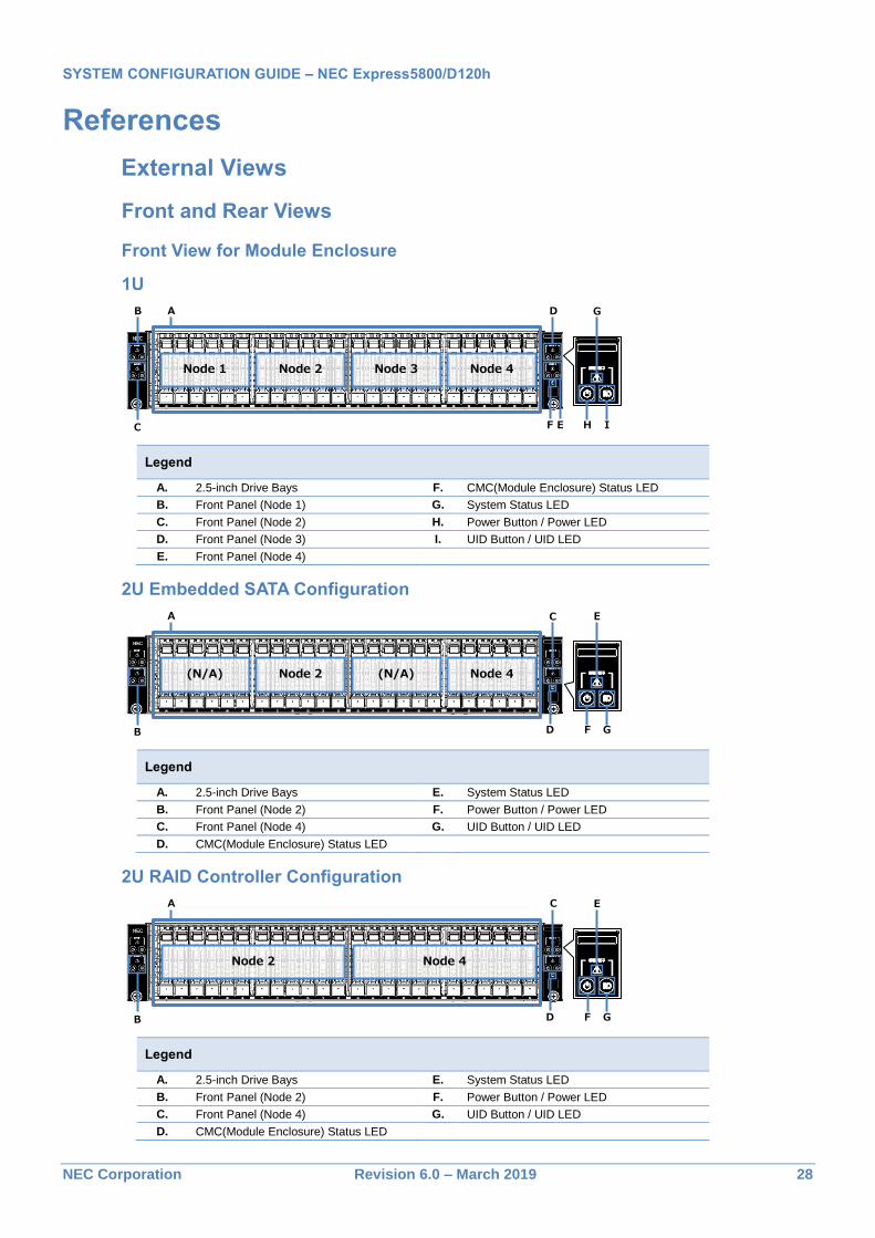
Front View for Module Enclosure
1U
Legend
A. 2.5-inch Drive Bays F. CMC(Module Enclosure) Status LED
B. Front Panel (Node 1) G. System Status LED
C. Front Panel (Node 2) H. Power Button / Power LED
D. Front Panel (Node 3) I. UID Button / UID LED
E. Front Panel (Node 4)
2U Embedded SATA Configuration
Legend
A. 2.5-inch Drive Bays E. System Status LED
B. Front Panel (Node 2) F. Power Button / Power LED
C. Front Panel (Node 4) G. UID Button / UID LED
D. CMC(Module Enclosure) Status LED
2U RAID Controller Configuration
Legend
A. 2.5-inch Drive Bays E. System Status LED
B. Front Panel (Node 2) F. Power Button / Power LED
C. Front Panel (Node 4) G. UID Button / UID LED
D. CMC(Module Enclosure) Status LED
AB
C
Node 1 Node 2 Node 3 Node 4
D
E HF I
G
A
B
(N/A) Node 2 (N/A) Node 4
C
FD G
E
A
B
Node 2 Node 4
C
FD G
E
SYSTEM CONFIGURATION GUIDE – NEC Express5800/D120h
NEC Corporation Revision 6.0 – March 2019 29
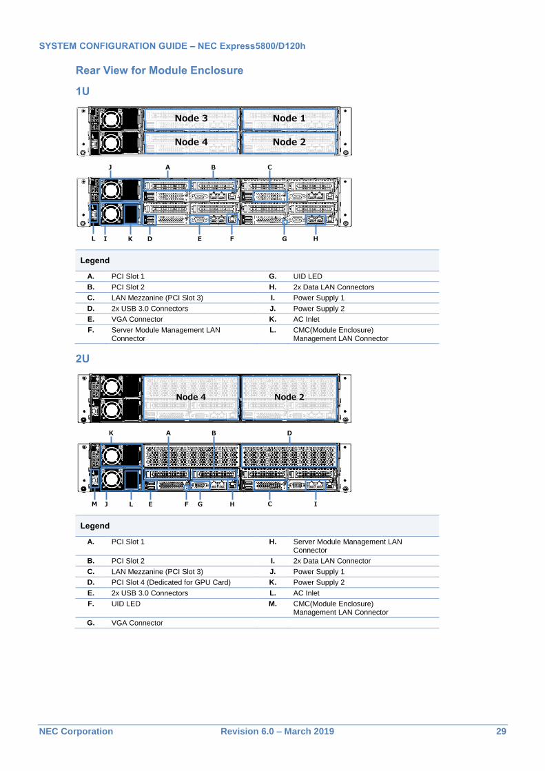
Rear View for Module Enclosure
1U
Legend
A. PCI Slot 1 G. UID LED
B. PCI Slot 2 H. 2x Data LAN Connectors
C. LAN Mezzanine (PCI Slot 3) I. Power Supply 1
D. 2x USB 3.0 Connectors J. Power Supply 2
E. VGA Connector K. AC Inlet
F. Server Module Management LAN Connector
L. CMC(Module Enclosure) Management LAN Connector
2U
Legend
A. PCI Slot 1 H. Server Module Management LAN Connector
B. PCI Slot 2 I. 2x Data LAN Connector
C. LAN Mezzanine (PCI Slot 3) J. Power Supply 1
D. PCI Slot 4 (Dedicated for GPU Card) K. Power Supply 2
E. 2x USB 3.0 Connectors L. AC Inlet
F. UID LED M. CMC(Module Enclosure) Management LAN Connector
G. VGA Connector
Node 1
Node 2
Node 3
Node 4
D
B C
E F G H
A
I
J
KL
Node 2Node 4
E
B
G HF I
A
J
K
LM C
D
SYSTEM CONFIGURATION GUIDE – NEC Express5800/D120h
NEC Corporation Revision 6.0 – March 2019 30
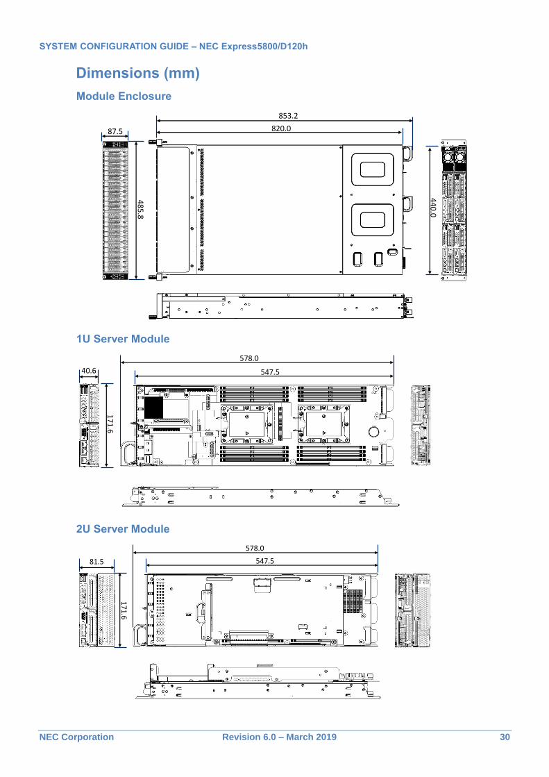
Dimensions (mm)
Module Enclosure
1U Server Module
2U Server Module
820.0
853.2
485.8
87.5
440.0
547.5
578.0
171.6
40.6
547.5
578.0
171.6
81.5
SYSTEM CONFIGURATION GUIDE – NEC Express5800/D120h
NEC Corporation Revision 6.0 – March 2019 31
General Supplementary Matters
HDD
Capacity of Hard disk drive is displayed in decimal not binary. 1GB=1000^3B、1TB=1000^4B.
PCI Expansion Slot
Transfer speed of PCI Express
PCI Express (PCIe): 2.5Gb/s (simplex) per lane
PCI Express 2.0 (PCIe 2.0): 5Gb/s (simplex) per lane
PCI Express 3.0 (PCIe 3.0): 8Gb/s (simplex) per lane
Time Display
The system clock is affected by temperature conditions in storage. If high accuracy of the system clock is required, use of NTP servers is recommended.
EXPRESSBUILDER
EXPRESSBUILDER DVD media is attached in the module enclosure with including following items
Server management software: ESMPRO/ServerManager, ESMPRO/ServerAgentService
SYSTEM CONFIGURATION GUIDE – NEC Express5800/D120h
NEC Corporation Revision 6.0 – March 2019 32
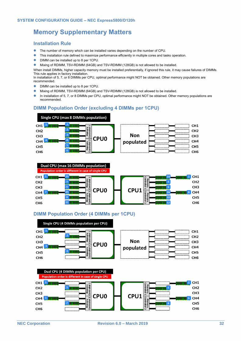
Memory Supplementary Matters
Installation Rule
The number of memory which can be installed varies depending on the number of CPU.
This installation rule defined to maximize performance efficiently in multiple cores and tasks operation.
DIMM can be installed up to 8 per 1CPU.
Mixing of RDIMM, TSV-RDIMM (64GB) and TSV-RDIMM (128GB) is not allowed to be installed.
When install DIMMs, higher capacity memory must be installed preferentially, if ignored this rule, it may cause failures of DIMMs. This rule applies in factory installation. In installation of 5, 7, or 8 DIMMs per CPU, optimal performance might NOT be obtained. Other memory populations are recommended.
DIMM can be installed up to 8 per 1CPU.
Mixing of RDIMM, TSV-RDIMM (64GB) and TSV-RDIMM (128GB) is not allowed to be installed.
In installation of 5, 7, or 8 DIMMs per CPU, optimal performance might NOT be obtained. Other memory populations are recommended.
DIMM Population Order (excluding 4 DIMMs per 1CPU)
DIMM Population Order (4 DIMMs per 1CPU)
SYSTEM CONFIGURATION GUIDE – NEC Express5800/D120h
NEC Corporation Revision 6.0 – March 2019 33
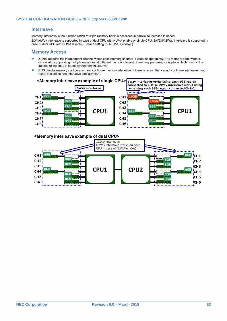
Interleave
Memory interleave is the function which multiple memory bank is accessed in parallel to increase in speed.
2/3/4/6Way interleave is supported in case of dual CPU with NUMA enable or single CPU. 2/4/6/8/12Way interleave is supported in case of dual CPU with NUMA disable. (Default setting for NUMA is enable.)
Memory Access
D120h supports the independent channel which each memory channel is used independently. The memory band width is increased by populating multiple memories at different memory channel. If memory performance is placed high priority, it is capable to increase in speed by memory interleave.
BIOS checks memory configuration and configure memory interleave. If there is region that cannot configure interleave, that region is used as non-interleave configuration.
SYSTEM CONFIGURATION GUIDE – NEC Express5800/D120h
NEC Corporation Revision 6.0 – March 2019 34
Example of memory configuration to enable memory interleave
Select following configuration that support interleave if increasing memory access in speed is needed.
In case that NUMA setting is disabled at BIOS set up menu, 2/4/6/8/12Way interleave is supported in dual CPU configuration depending on configuration.
Interleave configuration of “Dual CPU+NUMA enable” or “Single CPU”
Memory Capacity
Memory interleave mode
2Way 3Way 4Way 6Way 16GB 2x 8GB DIMM - -
24GB - 3x 8GB DIMM -
32GB 2x 16GB DIMM - 4x 8GB DIMM -
48GB - 3x 16GB DIMM 6x 8GB DIMM
64GB 2x 32GB DIMM - 4x 16GB DIMM -
96GB - 3x 32GB DIMM 6x 16GB DIMM
128GB 2x 64GB DIMM - 4x 32GB DIMM -
192GB - 3x 64GB DIMM 6x 32GB DIMM
256GB 2x 128GB DIMM - 4x 64GB DIMM -
384GB - 3x 128GB DIMM 6x 64GB DIMM
512GB - - 4x 128GB DIMM -
768GB - - 6x 128GB DIMM
SYSTEM CONFIGURATION GUIDE – NEC Express5800/D120h
NEC Corporation Revision 6.0 – March 2019 35
Internal Drive Supplementary Matters
Conditions of internal drive configuration in BTO Shipment
In BTO Shipment, there are some required conditions of Drive Types and RAID levels as below.
Common
In BTO Shipment, internal drives are included in the packing of Server Module. Internal drives are not mounted in the Module Enclosure. RAID configuration is pre-configured in BTO Shipment
All drives in BTO Shipment should be the same type, the same sector, and the same rotation speed.
For the shipment with RAID array, arrange the drives in the same capacity as many as needed.
RAID controller configuration in BTO Shipment
RAID level 0, 1, 5, 6, 10 can be installed for BTO Shipment. Selectable RAID levels are depending on the RAID controller.
Capacity of logical drive can be within 2TB with legacy boot mode, capacity of logical drive can be within the total capacity of logical disks with UEFI boot mode.
As factory shipment, initial cache policy of RAID controllers is Write Through. If customer set Write back, using UPS is recommended because there is a possibility that the data is lost by the blackout.
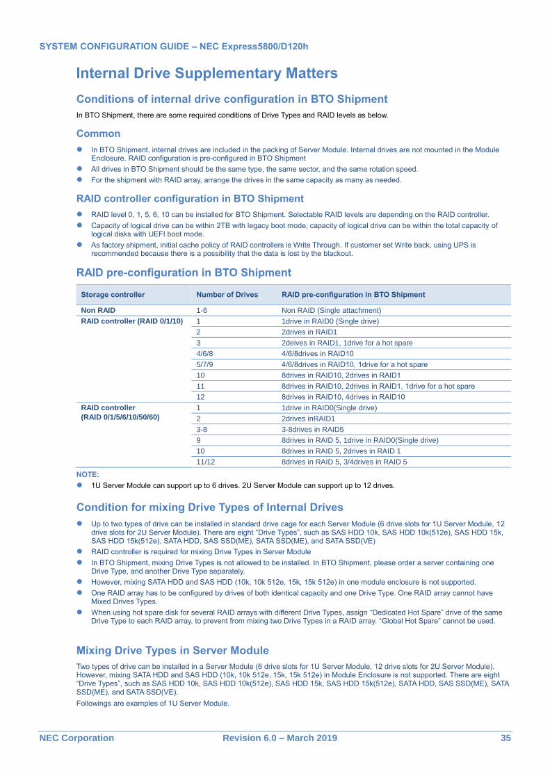
RAID pre-configuration in BTO Shipment
Storage controller Number of Drives RAID pre-configuration in BTO Shipment
Non RAID 1-6 Non RAID (Single attachment)
RAID controller (RAID 0/1/10) 1 1drive in RAID0 (Single drive)
2 2drives in RAID1
3 2deives in RAID1, 1drive for a hot spare
4/6/8 4/6/8drives in RAID10
5/7/9 4/6/8drives in RAID10, 1drive for a hot spare
10 8drives in RAID10, 2drives in RAID1
11 8drives in RAID10, 2drives in RAID1, 1drive for a hot spare
12 8drives in RAID10, 4drives in RAID10
RAID controller
(RAID 0/1/5/6/10/50/60)
1 1drive in RAID0(Single drive)
2 2drives inRAID1
3-8 3-8drives in RAID5
9 8drives in RAID 5, 1drive in RAID0(Single drive)
10 8drives in RAID 5, 2drives in RAID 1
11/12 8drives in RAID 5, 3/4drives in RAID 5
NOTE:
1U Server Module can support up to 6 drives. 2U Server Module can support up to 12 drives.
Condition for mixing Drive Types of Internal Drives
Up to two types of drive can be installed in standard drive cage for each Server Module (6 drive slots for 1U Server Module, 12 drive slots for 2U Server Module). There are eight “Drive Types”, such as SAS HDD 10k, SAS HDD 10k(512e), SAS HDD 15k, SAS HDD 15k(512e), SATA HDD, SAS SSD(ME), SATA SSD(ME), and SATA SSD(VE)
RAID controller is required for mixing Drive Types in Server Module
In BTO Shipment, mixing Drive Types is not allowed to be installed. In BTO Shipment, please order a server containing one Drive Type, and another Drive Type separately.
However, mixing SATA HDD and SAS HDD (10k, 10k 512e, 15k, 15k 512e) in one module enclosure is not supported.
One RAID array has to be configured by drives of both identical capacity and one Drive Type. One RAID array cannot have Mixed Drives Types.
When using hot spare disk for several RAID arrays with different Drive Types, assign “Dedicated Hot Spare” drive of the same Drive Type to each RAID array, to prevent from mixing two Drive Types in a RAID array. “Global Hot Spare” cannot be used.
Mixing Drive Types in Server Module
Two types of drive can be installed in a Server Module (6 drive slots for 1U Server Module, 12 drive slots for 2U Server Module). However, mixing SATA HDD and SAS HDD (10k, 10k 512e, 15k, 15k 512e) in Module Enclosure is not supported. There are eight “Drive Types”, such as SAS HDD 10k, SAS HDD 10k(512e), SAS HDD 15k, SAS HDD 15k(512e), SATA HDD, SAS SSD(ME), SATA SSD(ME), and SATA SSD(VE).
Followings are examples of 1U Server Module.
SYSTEM CONFIGURATION GUIDE – NEC Express5800/D120h
NEC Corporation Revision 6.0 – March 2019 36
Mixing Drive Types in a Module Enclosure
Mixing SATA HDD and SAS HDD (10k, 15k) in a Module Enclosure is not supported. The internal drives should be selected from a group of “SATA HDD, SATA SSD, and SAS SSD” and “SAS HDD(10k), SAS HDD(15k), SATA SSD, and SAS SSD” for mounting in Module Enclosure. “SAS HDD (10k)” contains the Drive Types, both SAS HDD 10k and SAS HDD 10k (512e). “SAS HDD (15k)” contains the Drive Types, both SAS HDD 15k and SAS HDD 15k (512e).
Followings are examples of Module Enclosure (1U).
SYSTEM CONFIGURATION GUIDE – NEC Express5800/D120h
NEC Corporation Revision 6.0 – March 2019 37
Server Module mounting location in case of mounting SATA HDD
In case of mounting SATA HDD, please locate the Server Module with SATA HDD in the Module Enclosure in accordance with following table in order to maximize performance. If Server Module is mounted at the location that is not listed in following table, it is not supported because the performance is not maximized. The configuration of three 1U Server Modules with SATA HDD is also not supported. There is no limitation to the Server Module location in the configuration of the Server Module without SATA HDD.
1U Server Module
Server Module
Number of node
# Drive cage 1
(Node 1) Drive cage 2
(Node 2) Drive cage 3
(Node 3) Drive cage 4
(Node 4)
1U (2U4node) 2node 1 SATA HDD SSD - -
2 SATA HDD - - SATA HDD
3node 3 SATA HDD SSD SSD -
4 SATA HDD SSD - SATA HDD
4node 5 SATA HDD SSD SSD SSD
6 SATA HDD SSD SSD SATA HDD
7 SATA HDD SATA HDD SATA HDD SATA HDD
SSD: The configuration which only SATA SSD and/or SAS SSD is mounted in the cage (SATA HDD is not included in one drive cage).
SATA HDD: The configuration which equal or more than one SATA HDD is mounted (Including the mixing case of SSD and SATA HDD in one drive cage).
2U Server Module
In case of 2U Server Module, not only Server Module location but also SATA HDD drive location depending on SATA HDD quantity has to accord with the following table in order to maximize performance
Server Module
Number of node
# Drive cage 1
(Node 2) Drive cage 2
(Node 2) Drive cage 3
(Node 4) Drive cage 4
(Node 4)
2U (2U2node)
2node 8 SATA HDD SSD
9 - SATA HDD - SATA HDD
10 SATA HDD SATA HDD
11 SATA HDD SATA HDD
SYSTEM CONFIGURATION GUIDE – NEC Express5800/D120h
NEC Corporation Revision 6.0 – March 2019 38
SSD: The configuration which only SATA SSD and/or SAS SSD is mounted in the cage (SATA HDD is not included in drive cage for a Server Module).
SATA HDD: The configuration which equal or more than one SATA HDD is mounted (Including the mixing case of SSD and SATA HDD in drive cage for a Server Module).
SYSTEM CONFIGURATION GUIDE – NEC Express5800/D120h
NEC Corporation Revision 6.0 – March 2019 39
Server Management BMC (Baseboard Management Controller), integrated into the server, provides superior remote control and system management features listed in the table below.
Boot monitoring BIOS/POST stall, Booting, OS stall, shutdown 1
1
Alerting HW error, Boot error , and OS panic
(by SNMP, E-Mail)
Remote KVM
(via LAN)
POST/BIOS setup, ROM utility
Panic screen, Boot screen 2,
CUI-based screen (OS console)
GUI-based screen (OS console) -
Plugin-less GUI-based screen (HTML5) -
Remote control
(via LAN)
Remote reset/power on-off/ dump
Remote power capping
BIOS/BMC FW update
OS shutdown 1
1
Remote media (CD/DVD/FD/USB) -
CLP (Command Line Protocol) (DMTF compliant)
Remote control via Web browser (multi user login at the same time)
Others Set automatic IP address via DNS/DHCP
LDAP/Active Directory verification/user control
Clock synchronization 3
3
IPMI 2.0 2.0
IPv6(Web console/CLP only)
Redfish™ API
1 The feature is not supported on VMware ESXi systems. 2 Monitoring boot screens is not supported on VMware systems. 3 Requires installation of the NEC ESMPRO ServerAgentService to synchronize clock of the BMC and the RTC. Or enabling the
NTP (Network Time Protocol) setting of the BMC to synchronize clock of the BMC and remote server if the NEC ESMPRO ServerAgentService cannot be installed to the server.
SYSTEM CONFIGURATION GUIDE – NEC Express5800/D120h
NEC Corporation Revision 6.0 – March 2019 40
OS Support Matrix for PCI Cards and Embedded Controller
Part Number Product Name
WS
201
2R
2
WS
201
6
RH
EL
7.3
ES
Xi 6
.0
ES
Xi 6
.5
ES
Xi 6
.7
- Embedded SATA Controller
- Embedded 10GbE NIC
N8103-199 SAS Controller
N8103-188 RAID Controller (0GB, RAID 0/1)
N8103-176A RAID Controller (1GB, RAID 0/1)
N8103-177A RAID Controller (1GB, RAID 0/1/5/6)
N8103-178A RAID Controller (2GB, RAID 0/1/5/6)
N8103-184 SAS Controller
N8190-161 Fibre Channel Controller (1ch)
N8190-162 Fibre Channel Controller (2ch)
N8104-150 1000BASE-T Adapter
N8104-151 Dual Port 1000BASE-T Adapter
N8104-152 Quad Port 1000BASE-T Adapter
N8104-149 10GBASE SFP+ Adapter (SFP+/2ch)
N8104-158 10GBASE Adapter (SFP+/2ch)
N8104-159 10GBASE Adapter (QSFP+/4ch) - - - - -
N8104-157 Dual Port 10GBASE-T Adapter
N8104-168 Quad Port 1000BASE-T Adapter
N8104-170 Dual Port 10GBASE-SFP+ Adapter
SYSTEM CONFIGURATION GUIDE – NEC Express5800/D120h
SYSTEM CONFIGURATION GUIDE – NEC Express5800/D120h
NEC Corporation Revision 6.0 – March 2019 42
Expansion Slots
1U Server Module
Slot Name Standard Bus Width
Connector Width
Height Length Processor
Slot 1 PCIe 3.0 x16 x16 Low Profile Up to 220 mm CPU1
Slot 2 PCIe 3.0 X8 x8 Low Profile Up to 220 mm CPU1
LAN Mezz. PCIe 3.0 x16 x16 - - CPU1
2U Server Module
Slot Name Standard Bus Width
Connector Width
Height Length Processor
Slot 1 PCIe 3.0 x16 x16 Low Profile Up to 220 mm CPU1
Slot 2 PCIe 3.0 X8 x8 Low Profile Up to 220 mm CPU1
LAN Mezz. PCIe 3.0 x16 x16 - - CPU1
Slot 4 PCIe 3.0 x16 x16 - - CPU2
Slot 1 Slot 2
LAN Mezz.
Slot 1 Slot 2
Slot 4
LAN Mezz.
SYSTEM CONFIGURATION GUIDE – NEC Express5800/D120h
NEC Corporation Revision 6.0 – March 2019 43
Supported Tape and Removal Disk Backup Drive List See the following table for supported tape and removal disk backup drives. An optional tape drive enclosure is needed to connect the backup drives to the server.
Category Product Name / Description Part Number
LTO Internal LTO (SAS)
LTO4, Half height, Native capacity 800 GB
N8151-127
Internal LTO (SAS)
LTO5, Half height, Native capacity 1.5 TB
N8151-128
Internal LTO (SAS)
LTO6, Half height, Native capacity 2.5 TB
N8151-129
Internal LTO (SAS)
LTO7, Half height, Native capacity 6 TB
N8151-136
RDX Internal RDX (USB)
N8151-125
Boot Mode Setting The server supports Legacy mode and UEFI mode (default) as an OS Boot Mode. See the table below for the Boot Mode and X2APIC setting for each Operating System. As the default settings at the factory, UEFI mode is set as OS Boot mode and X2APIC is enabled. Refer to the User’s Guide and change the settings before installing an Operating System requiring Legacy Mode.
Operating System Supported Boot Mode Supported X2APIC Setting
Windows Server 2012 R2 UEFI Enabled
Windows Server 2016 UEFI Enabled
Red Hat Enterprise Linux 7 UEFI Enabled
VMware ESXi 6.0 Update3 UEFI Enabled
VMware ESXi 6.5 Update1 UEFI Enabled
VMware ESXi 6.7 UEFI Enabled
Secure Boot Mode This server supports Secure Boot. It is supported with UEFI Boot mode and protects the security by only allowing software programs with digital signature to run. The supported operating systems, software, and boot devices are below. The default setting of Secure Boot is disabled. Keep the setting disabled to use other operating systems and/or software.
Supported OS and Software for Secure Boot Mode
Operating System Supported Boot Mode Secure Boot Mode
Windows Server 2012 R2 UEFI
Windows Server 2016 UEFI
VMware ESXi 6.5 UEFI
VMware ESXi 6.7 UEFI
Software Related to Boot Supported Boot Mode Secure Boot Mode
System Diagnostics Utility UEFI
EXPRESSBUILDER UEFI
Supported Boot Device for Secure Boot Mode
Supported Boot Device Part Number
RAID controller (RAID0/1) N8103-188
RAID Controller (1GB, RAID 0/1) N8103-176A
RAID Controller (1GB, RAID 0/1/5/6) N8103-177A
RAID Controller (2GB, RAID 0/1/5/6) N8103-178A
SYSTEM CONFIGURATION GUIDE – NEC Express5800/D120h
NEC Corporation Revision 6.0 – March 2019 44
Copyright Notice and Liability Disclaimer The information contained herein is subject to change without notice.
Microsoft and Windows Server are either registered trademarks or trademarks of Microsoft Corporation in the United States and/or other countries
Intel and Xeon are registered trademarks or trademarks of Intel Corporation or its subsidiaries in the United States and other countries.
Linux is a trademark of Linus Torvalds.
Red Hat is a registered trademark of Red Hat, Inc. in the U.S.
All other products, brands, or trade names used in this document are trademarks or registered trademarks of their respective holders.
NEC shall not be liable for technical or editorial errors or omissions contained herein.
For hard drive capacity measurements, 1 GB = 1 billion bytes. Actual formatted capacity is less.
SYSTEM CONFIGURATION GUIDE – NEC Express5800/D120h