1 Building Enclosure Design, Systems & Assemblies Presented by Fiona Aldous Building Enclosure Commissioning: Train the Trainer Iowa State University, Ames Iowa May 10‐12, 2016 NIST reports that up to 43% of heating and 26% of cooling energy used by buildings is added due to infiltration. 1. (Pollock, 2001) Need for EBCx Steven J. Emmerich, Timothy P. McDowell and Wangdy Anis “Investigation of the impact of Commercial Building Envelope Air Tightness on HVAC Energy Use” U.S. Department of Energy, Office of Building Technologies, 2005 “Predicted potential annual heating and energy cost savings for these (commercial) buildings ranged from 2% to 36% with the largest savings occurring in the heating‐dominated climates of Minneapolis and Bismark.” Controlling Air Flow Brief History • First work in 1940s at University of Minnesota ‐ resulted in building paper used as “drainage plane” (i.e., breathable membrane now known as a “water‐resistive barrier”) • Increased levels of insulation started being used in 1960s, resulting in moisture in walls • As a result, vapor retarders incorporated starting in 1970s, but still had failures • Discussions of “airtightness” started in 1980s and with initial implementations in 1990s in Canada (NBCC) • Original air barrier – polyethylene, then ½ inch drywall • In 2001, an “air barrier” became a requirement in the Massachusetts building code Air infiltration & exfiltration - major cause of rain penetration - uncontrolled, untreated infiltrating air - waste energy, increased condensation & envelope deterioration - limits transfer of noise, odor, fire and smoke - disrupts ability to control indoor humidity - disrupts interior HVAC design pressures (comfort, infection control and IAQ problems) The Air Barrier: • Below Grade Waterproofing • Waterproofing at Grade &/or elevated decks • Exterior Wall • Roof Air / Moisture Barrier concept: Provide a continuous air barrier assembly that has an air leakage not to exceed 0.040 cubic feet per square foot per minute under a pressure differential of 0.3 in. water (1.57 pounds per square foot) (0.20 liters per second per square meter at 75 Pascals) when tested in accordance with ASTM E 2357. Assembly shall perform as a liquid drainage plane flashed to discharge condensation or water penetration to the exterior. Assembly shall accommodate movements of building materials by providing expansion and control joints as required, with accessory air and vapor seal materials at such locations, changes in substrate and perimeter conditions. - Assembly shall be capable of withstanding positive and negative combined design wind, fan and stack pressures on the envelope without damage or displacement, and shall transfer the load to the structure. - Assembly shall not displace adjacent materials under full load. - Assembly shall be joined in an airtight and flexible manner to the air barrier material of adjacent assemblies, allowing for the relative movement of assemblies due to thermal and moisture variations and creep, and anticipated seismic movement. ABAA, Specification 07261 – Air Barrier, Part 1.2, B Performance What is an air barrier? • Principal material identified in a building assembly as being the primary plane of air tightness • A continuous plane of air-tightness must be traced throughout the building envelope with all joints made air-tight
Transcript
1
Building Enclosure Design, Systems & Assemblies
Presented by
Fiona Aldous
Building Enclosure Commissioning:Train the TrainerIowa State University,
Ames IowaMay 10‐12, 2016
NIST reports that up to 43% of heating and 26% of cooling energy used by buildings is added due to infiltration.
1. (Pollock, 2001)
Need for EBCx
Steven J. Emmerich, Timothy P. McDowell and Wangdy Anis“Investigation of the impact of Commercial Building Envelope Air Tightness on HVAC Energy Use”U.S. Department of Energy, Office of Building Technologies, 2005
“Predicted potential annual heating and energy cost savings for these (commercial) buildings ranged from 2% to 36% with the largest savings occurring in the heating‐dominated climates of Minneapolis and Bismark.”
Controlling Air Flow
Brief History• First work in 1940s at University of Minnesota ‐ resulted in building
paper used as “drainage plane” (i.e., breathable membrane now known as a “water‐resistive barrier”)
• Increased levels of insulation started being used in 1960s, resulting in moisture in walls
• As a result, vapor retarders incorporated starting in 1970s, but still had failures
• Discussions of “airtightness” started in 1980s and with initial implementations in 1990s in Canada (NBCC)
• Original air barrier – polyethylene, then ½ inch drywall
• In 2001, an “air barrier” became a requirement in the Massachusetts building code
- disrupts interior HVAC design pressures (comfort, infection control and IAQ problems)
The Air Barrier:
• Below Grade Waterproofing
• Waterproofing at Grade &/or elevated decks
• Exterior Wall
• Roof
Air / Moisture Barrier concept:
Provide a continuous air barrier assembly that has an air leakage not to exceed 0.040 cubic feet per square foot per minute under a pressure differential of 0.3 in. water (1.57 pounds per square foot) (0.20 liters per second per square meter at 75 Pascals) when tested in accordance with ASTM E 2357. Assembly shall perform as a liquid drainage plane flashed to discharge condensation or water penetration to the exterior. Assembly shall accommodate movements of building materials by providing expansion and control joints as required, with accessory air and vapor seal materials at such locations, changes in substrate and perimeter conditions.
- Assembly shall be capable of withstanding positive and negative combined design wind, fan and stack pressures on the envelope without damage or displacement, and shall transfer the load to the structure.
- Assembly shall not displace adjacent materials under full load.
- Assembly shall be joined in an airtight and flexible manner to the air barrier material of adjacent assemblies, allowing for the relative movement of assemblies due to thermal and moisture variations and creep, and anticipated seismic movement.
ABAA, Specification 07261 – Air Barrier, Part 1.2, B Performance
What is an air barrier?
• Principal material identified in a building assembly as being the primary plane of air tightness
• A continuous plane of air-tightness must be traced throughout the building envelope with all joints made air-tight
2
Assembly shall be continuous over the entire building enclosure, joined in an airtight and flexible manner to the air barrier material of adjacent assemblies, allowing for the relative movement of assemblies due to thermal and moisture variations and creep, and anticipated seismic movement.
Assembly shall be capable of withstanding forces of positive and negative combined design wind, fan and stack pressures on the envelope without damage or displacement, and shall transfer the load to the structure. Assembly shall not displace adjacent materials under full load.
approaches to air barrier:
interior using gypsum board or plastic sheeting
exterior using sheathing
exterior using an air barrier assembly
misconceptions
It’s not necessarily a vapor barrier…the terms are not interchangeable!
Air barrier will control the passage of air from/between spaces…more than one?
material: air leakage of the air barrier may not exceed 0.02 l/m²·s @75 Pa (0.004 cfm of air per ft² at a pressure difference of 0.3 inches of water 1.57 psf) per ASTM E2178….which equates to the air permeance of ½ inch thick drywall
assembly: air leakage of the air barrier assembly may not exceed 0.2L/(s•m2) @ 75Pa. (0.04 cfm/ft2 @ 1.57 psf)test combines the primary air barrier material with supporting air barrier accessories such as transition membranes and sealants to form a complete air barrier assembly per ASTM E2357
definition What are Air Barrier Materials?– Modified bitumen
- Concrete Masonry Units (CMU)- Expanded polystyrene foam- Building paper- Open cell foam- Some housewraps- Perlite board- Fiberboard- Glass fiber rigid board- Cellulose insulation- Most damp-proofings
code compliance
air barrier compliance option: iecc 2012, C402.4.1.2.3 /ashrae 90.1 (2010)
whole building: the completed building shall be tested and the air leakage rate of the building envelope shall not exceed 2.0L/(s•m2) @ 75Pa (0.40 cfm/ft2 @ 1.57 psf) per ASTM E779 or equivalent
NFPA 285 “Standard Fire Test Method for Evaluation of Fire Propagation Characteristics of exterior Non-load-bearing Wall assemblies Containing Combustible Components”
ICC IBC 2012, 1403.5 Vertical and lateral flame propagation. Exterior walls on buildings of Type I, II, III or IV construction that are greater than 40 feet (12 192mm) in height above grade plane and contain a combustible water-resistive barrier shall be tested in accordance with and comply with the acceptance criteria of NFPA 285.
exterior air barrier assembly
The air barrier can be located anywhere in the enclosure assembly
On the warm side, it can be a combination air and vapor barrier
If it is located on the cold side, it should have a permeance at least 10 times the permeance of the vapor barrier Building Science Corp,
Lstiberek
3
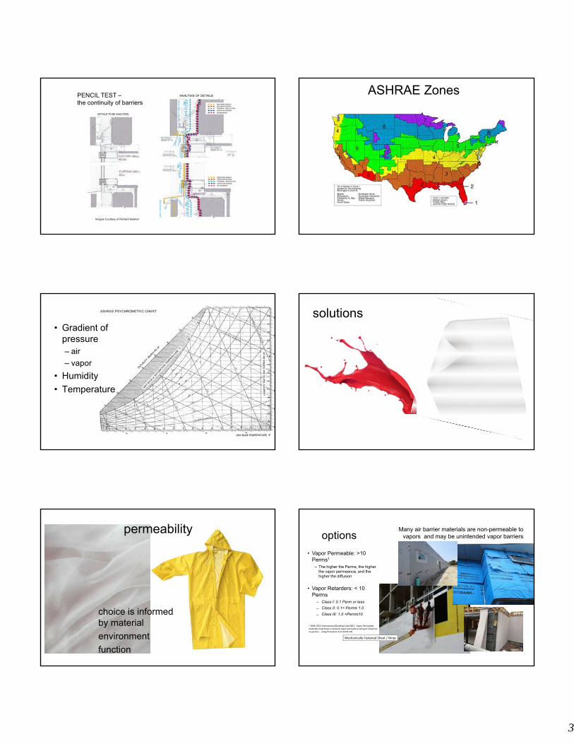
PENCIL TEST –the continuity of barriers
Images Courtesy of Richard Keleher
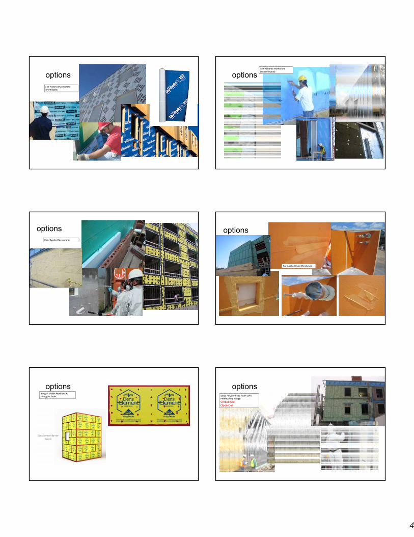
ASHRAE Zones
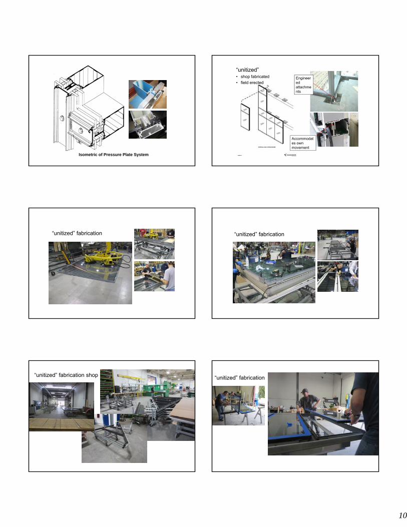
• Gradient of pressure – air
– vapor
• Humidity
• Temperature
solutions
permeability
choice is informed by material
environment
function
options
Mechanically Fastened Sheet / Wrap
• Vapor Permeable: >10 Perms1
− The higher the Perms, the higher the vapor permeance, and the higher the diffusion
• Vapor Retarders: < 10 Perms
Class I: 0.1 Perm or less
Class II: 0.1< Perm≤ 1.0
Class III: 1.0 <Perm≤10
1 2009 /2012 International Building Code (IBC): Vapor Permeable materials must have a moisture vapor permeance rating of 10 perms or greater… using Procedure A of ASTM E96.
Many air barrier materials are non-permeable to vapors and may be unintended vapor barriers
4
optionsSelf‐Adhered Membrane(Permeable)
optionsSelf‐Adhered Membrane(Impermeable)
optionsFluid Applied Membranes
options
Pre‐Applied Fluid Membrane
optionsIntegral Water Repellant & Fiberglass facer:
Below Grade Waterproofing• Restricts the passage of water through an element even in the presence of
hydrostatic pressure.
• Waterproofing materials must be impervious to water and have a low permeability. Can be used in combination with a below slab vapor barrier.
• May be adhered (fully bonded), or partially adhered or loose laid (unbonded)– Sheet HDPE (High Density Polyethylene) forms integral bond with concrete– Sheet Bentonite membrane forms impermeable layer in contact with moisture and
under compression– Sheet rubberized asphalt membrane adhered to free standing walls
• Typical designs:– Positive side – Pre-applied or post applied to structure– Wall Only design– Perimeter drainage systems vs. underslab drainage– Negative side – Applied to interior of structure
Below Grade Waterproofing
System design:
Positive Side Waterproofing, such as “bath tub” design.
Must resist hydrostatic pressure
Wall Only Waterproofing, with perimeter &/or under slab drainage & vapor barrier
Below Grade WaterproofingWall only waterproofing with HDPE membrane
Sheet rubberized asphalt membrane
HDPE Vapor Barrier to wall
Waterproofing• Restricts the passage of water through an element even in the presence of
hydrostatic pressure.
• Materials must be impervious to water and have a low permeability.
• May be adhered (fully bonded), or partially adhered or loose laid (unbonded)– Fluid applied– Sheet membrane– Traffic coating – not considered waterproofing
Reinforced hot fluid applied rubberized asphalt membrane
Bonded vs. Unbonded Membranes
• Bonded systems minimize concern of lateral migration of water. These systems localize leaks and confine defects to small areas. They are fabricated in the field.
• Unbonded materials easily span cracks and construction joints. These systems allow lateral migration of water at any defective area. They are placed/assembled in the field.
Disadvantages• Single line of defense• Sensitive to puncture
damage• Minor workmanship
defects are problematic
Elastomeric Sheet Systems
Modified Bituminous Systems
• Elastomeric characteristics
• Include both SBS and APP chemical formulations and variable scrim reinforcement choices
• Attachment methods include self-adhered sheets, adhesives, heat-welding, and hot-mop applications
Protection Board• Protect membrane from construction traffic• Asphalt-based laminates• Coordinate installation with flood testing
Drainage Course• Prefabricated drainage mats• Stone, aggregate, or pea gravel
Thermal InsulationInstalled above membrane:• Regulates temperature of membrane• Additional layer of protection• Extruded polystyrene board
– Compressive strength– Moisture resistance
Additional System Components
7
Exterior Wall Assemblies:
The vertical components assembled to create the walls of the building envelope:
• Drainage Wall Systems • Pressure equalized rain-
screens• Barrier Wall Systems• Skylight and Glazed
Canopies
Drainage Wall Systems
– A wall cladding system that is comprised of a primary drainage plane and an exterior weathering plane, i.e. masonry veneer
– Typically Non-load bearing
– Flashings control and direct moisture to exterior
– Resists water infiltration by deflection and drainage cavity
– Commonly “design-bid-build” procurement method
Drainage Wall Systems
Air/Moisture barrier & Drainage Plane
Cladding Flashing
Continuous insulation
Drainage Wall Systems
Drainage Wall & Drying• Drying of Assembly
– Orientation & Exposure– Level of saturation– Repetition of wetting
cycles– Indoor/Outdoor
• Temperature/Humidity
– Physical Properties Wall Components
– Color of Materials– Vapor Permeance– Air movement
Contemporary Wall SystemsPressure Equalized
rainscreen walls– Typically Unitized or “stick-built”
Curtain wall
– Non-load bearing, engineered
– Resists water infiltration by equalizing differential air pressures across the depth of the wall assembly, often compartmentalized
– Typical complex designs developed with assistance from specialty contractor or consultant
8
Contemporary Wall Systems
Compartmentalized
Accommodates own movement
Engineered attachments
Unitized curtain wall
Precast Concrete panels with punch openings
Contemporary Wall Systems
Barrier walls– Curtain wall, precast
concrete, thin stone, metal panels, composite panels
– Non-load bearing
– Resists water infiltration by deflection only
– Often reliant upon sealant to achieve greater transparency
Contemporary Wall Systems
Relies upon sealant at joints between panels
Engineered systemsealant profile
Backer Rod
width : depth2 : 1
Sealantdepth
width
(1/4 in. < B < 1/2 in.)
Perform field adhesion tests
Fenestrationwindow:
An opening constructed in a wall or roof and functioning to admit light or air to an enclosure, usually framed and spanned with glass mounted to permit opening and closing. (From the old Norse word “vindauga”, which is formed from “vinder”, wind, and “auga”, eye. Therefore a window is an “eye for the wind”.) - 101/I.S. 2/NAFS-02
storefront: Glazed openings at lower floors, constructed to withstand excessive use and enhanced visibility. Typically inside glazed.
window wall:“A type of metal curtain wall installed between floors or between floor and roof and typically composed of vertical and horizontal framing members, containing operable sash or ventilators, fixed lites or opaque panels or any combination thereof”. - AAMA CW-DG-1-96
curtain wall:“Any building wall, of any material, which carries no superimposed vertical loads i.e., any “non-load bearing” wall. - AAMA CW-DG-1-96
BARRIER
Exterior gaskets or sealant criticalto prevent moisture penetration
Glass or solid infillpanel
Glazing channelnot designed tocollect and drainany Water
Exterior Interior
Performance Characteristic
9
DRAINAGE / RAIN SCREEN
Gasket or sealant bead
Weep hole
Glass or solid infillpanel
Internal sealsrequired inglazing channel
Glazing channeldesigned to collectand drain any water thatpenetrates past exteriorback to outside
Exterior Interior
Performance Characteristic
PRESSURE-EQUALIZED
GreaterOutdoorPressure
LesserIndoor Pressure
AirSpac
e
Air Seal
exterior screen wall in front of a primary barrier wall.
Performance Characteristic
curtain wall
Any exterior building wall, of any material, which carries no superimposed vertical loads, i.e., any non-bearing wall
Types of glazed curtain wall:- stick built – field fabricated (screw spline or shear block)- unitized – shop fabricated and field erected- point supported glass – field erected
Typically exterior glazed. Resists water infiltration by equalizing differential air pressures across the depth of the wall assembly, often compartmentalized. Typically complex designs developed with assistance from specialty contractor or consultant
metal curtain wall:“An exterior curtain wall which may consist entirely or principally
of metal, or may be a combination of metal, glass and other surfacing materials supported by or within a metal framework.”
Window wall:“A type of metal curtain wall installed between floors or between floor and roof and typically composed of vertical and horizontal framing members, containing operable sash or ventilators, fixed lites or opaque panels or any combination thereof”. - AAMA CW-DG-1-96
slab edge cover
Traditional Wall Systems
Mass walls– Masonry, Stone, Terra
Cotta
– Load bearing
– Multiple wythe with solid collar joints
– Resists water infiltration by deflection and absorption
Traditional Wall Systems
Multi-wythe construction
Roof Systems
• Low Slope Designs <2:12– Single-ply
– Conventional B.U.R.
• Steep Slope Designs >3:12– Shingled Materials
– Standing seam metal
Low slope ballasted roof
Steep slope metal roof
13
Water ShedGravity Allows Quick Water Runoff
Underlayment Required
• Shingles– Bituminous
– Synthetic
• Slate
• Tile
• Cedar Shakes
• Metal
Steep Slope
• Increased reliance on referenced standards– FMG / UL – Manufacturer’s Details
(establishes a base line standard)
• Enhanced awareness of perimeter edge behavior
• Sustainability – Alternative shingle materials & “cool” metal coatings
Standing Seam Metal Roofing Shingle & Tile Roofing
Water BarriersWater Infiltration Prevented by Water Tight Membrane
• Built-up
• Single Ply
• Metal
• Protected Membrane Assembly
• Sprayed Polyurethane Foam
Low-Slope (Conventional Materials)
• Popularity in the design community remains strong
• Proven track record of success
• Attractive installed cost parameters
• Inherent redundancy in a field manufactured membrane
14
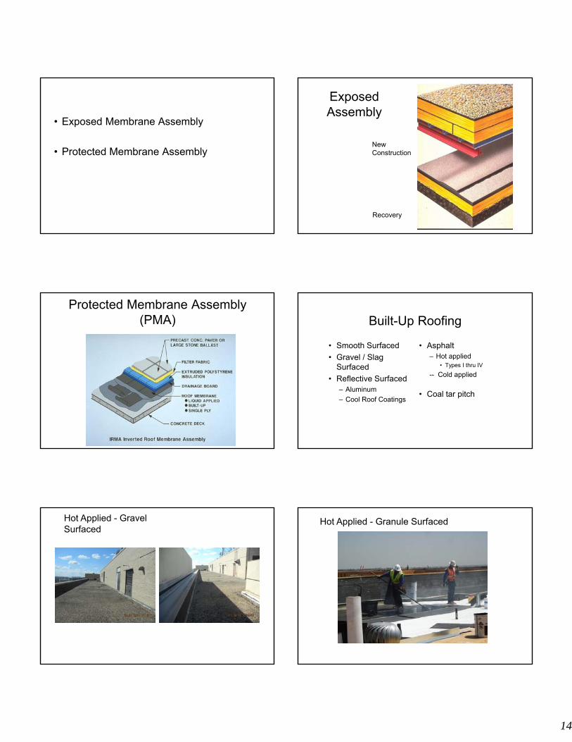
• Exposed Membrane Assembly
• Protected Membrane Assembly
Recovery
New Construction
Exposed Assembly
Protected Membrane Assembly(PMA) Built-Up Roofing
• Smooth Surfaced
• Gravel / Slag Surfaced
• Reflective Surfaced– Aluminum
– Cool Roof Coatings
• Asphalt– Hot applied
• Types I thru IV
-- Cold applied
• Coal tar pitch
Hot Applied - GravelSurfaced
Hot Applied - Granule Surfaced
15
Common Problems – Blister FormationCommon Problems - Poor Q/A during installation
Poor bond – insulation to deck
Common Problems – Flashing Defects
Slippage
Common Problems – Flashing Defects
Modified Bitumen
APP (Atactic Polypropylene)
SBS (Styrene Bitudiene Styrene)
Modified Bitumen Roof
16
Modified Bitumen Disadvantages
Under-torched Over-torched
Modified Bitumen
Single Ply Membrane Systems
• Thermoset– EPDM
• Thermoplastic– PVC, TPO, KEE &
others
Single Ply Configurations
• Adhered
• Mechanically fastened
• Ballasted
Single-ply designs Adhered
• Substrate important- cover board required
• Solvent or water based adhesive
• Spray foam adhesive, proprietary cold adhesive,
asphalt mopping adhesive
• Moisture diminishes adhesion
17
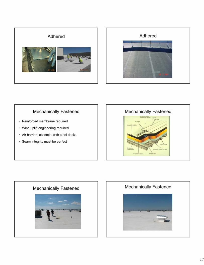
Adhered Adhered
Mechanically Fastened
• Reinforced membrane required
• Wind uplift engineering required
• Air barriers essential with steel decks
• Seam integrity must be perfect
Mechanically Fastened
Mechanically Fastened Mechanically Fastened
18
Mechanically Fastened Mechanically Fastened
Ballasted
• Difficult to maintain and repair
• Ballast requirements often conflict with structural
deck load capabilities
• Wind uplift engineering required
Ballasted
Sprague Building Roof
Ballasted Single Ply Issues
Perimeter Restraint Requirements
19
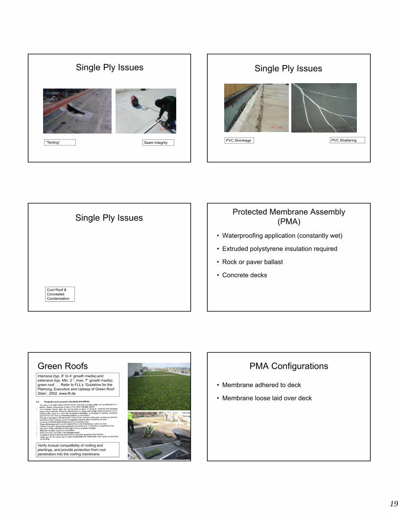
Single Ply Issues
“Tenting” Seam Integrity
Single Ply Issues
PVC Shrinkage PVC Shattering
Single Ply Issues
Cool Roof & Concealed Condensation
Protected Membrane Assembly(PMA)
• Waterproofing application (constantly wet)
• Extruded polystyrene insulation required
• Rock or paver ballast
• Concrete decks
Green RoofsIntensive (typ. 8” to 4’ growth media) and extensive (typ. Min. 2 “, max. 7” growth media) green roof …. Refer to FLL’s “Guideline for the Planning, Execution and Upkeep of Green Roof Sites”, 2002. www.fll.de
Verify mutual compatibility of roofing and plantings, and provide protection from root penetration into the roofing membrane.
PMA Configurations
• Membrane adhered to deck
• Membrane loose laid over deck
20
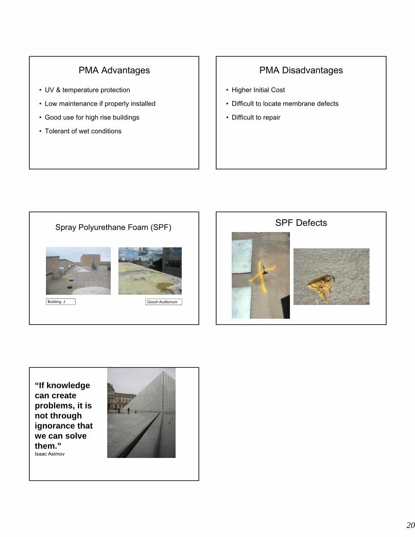
PMA Advantages
• UV & temperature protection
• Low maintenance if properly installed
• Good use for high rise buildings
• Tolerant of wet conditions
PMA Disadvantages
• Higher Initial Cost
• Difficult to locate membrane defects
• Difficult to repair
Spray Polyurethane Foam (SPF)
Building J Gooch Auditorium
SPF Defects
“If knowledge can create problems, it is not through ignorance that we can solve them.”Isaac Asimov