In 2000, an artificially structured composite was shown to exhibit
a negative index of refraction over a band of microwave
frequencies1. This demonstration of a previously unexploited
electromagnetic (EM) property proved the importance of
engineered materials and has resulted in an extraordinary amount
of continued development by scientists working in optics,
electromagnetism, physics, engineering, and materials science.
Experimental results revealing new phenomena and potential
applications for these artificial materials, more recently termed
metamaterials (MMs), have provided the basis for impressive
growth in this burgeoning field. EM-MMs exhibit exotic properties
not easily achieved using naturally occurring materials. In addition
to a negative index (NI) of refraction, properties such as artificial
magnetism2, negative permittivity, and negative permeability have
been observed in fabricated MM composites; these material
properties are either absent from conventional materials or are
difficult to achieve over various bands of the EM spectrum3,4. With
encouraging results having been demonstrated at microwave
frequencies, there has been a determined push to extend MMs to
the terahertz, infrared, and visible bands. The pursuit of these
higher frequency MMs has led to the establishment of many
research programs, conferences, workshops, and significant
funding efforts dedicated to understanding and developing MMs.
Progress has been rapid: although the entire subject of MMs is
relatively new1, the scaling of artificial structures has already been
demonstrated from radio frequencies (RFs)5 to millimeter-wave6,
Engineered materials composed of designed inclusions can exhibit exoticand unique electromagnetic properties not inherent in the individualconstituent components. These artificially structured composites, knownas metamaterials, have the potential to fill critical voids in theelectromagnetic spectrum where material response is limited and enablethe construction of novel devices. Recently, metamaterials that displaynegative refractive index – a property not found in any known naturallyoccurring material – have drawn significant scientific interest,underscoring the remarkable potential of metamaterials to facilitate newdevelopments in electromagnetism.
Willie J. Padilla†*, Dimitri N. Basov#, David R. Smith#§
†Materials Science & Technologies-Center for Integrated Nanotechnologies, Los Alamos National Laboratory, Los Alamos, NM 87545, USA#Physics Department, University of California San Diego, San Diego, CA 92037, USA§Department of Electrical & Computer Engineering, Duke University, Durham, NC 27708, USA
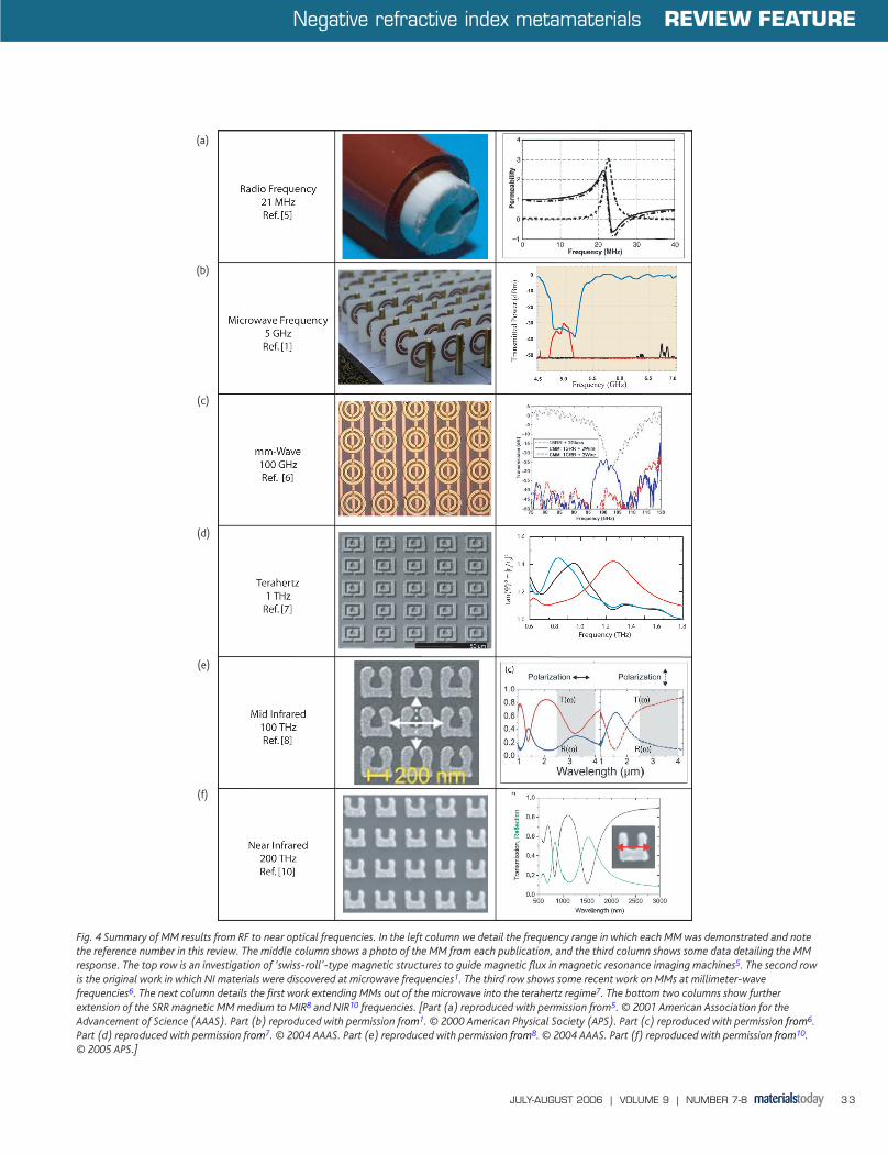
far infrared (FIR)7, mid-infrared (MIR)8,9, and near infrared (NIR)10
wavelengths, spanning nearly seven orders of magnitude in
frequency. With MM design and fabrication procedures becoming
increasingly routine, the prospect of designer materials with a
range of new and selectable EM properties at nearly any
wavelength band is nearing reality. By providing access to new
realms of material response, MMs have and will continue to
impact the fields of physics, materials science, engineering, optics,
nanotechnology, and many others branches of science.
Since 2000, the rate of publications on EM-MMs has grown
exponentially11, indicative of the intense interest that artificial
materials have generated. Much of that interest has been sparked by
the prospect of MMs with negative refractive index – a property not
found in nature. In this review, we focus on artificial structures formed
by repeated elements whose physical dimension and spacing are less
than the wavelengths of interest, and can be treated as homogeneous
to good approximation. For more detailed information on MMs and NI,
including the prospects of achieving negative refraction in photonic
crystals and other systems, the reader is referred to several review
articles12-14 and books15-17 on the subject.
EM response of materialsTo understand MMs, it is necessary to understand material response to
EM waves in general. EM response in homogeneous materials is
predominantly governed by two parameters. One of these parameters,
ε(ω), describes the response of a material to the electric component of
light (or other EM wave) and the other, µ(ω), to the magnetic
component at a frequency ω. Both of these parameters are typically
frequency-dependent complex quantities, and thus there are in total
four numbers that completely describe the response of an isotropic
material to EM radiation at a given frequency,
ε(ω) = ε1(ω) + iε2(ω)
µ(ω) = µ1(ω) + iµ2(ω). (1)
For most materials, the two complex quantities ε and µ are the only
relevant terms and hence dictate the response between light and
matter. Among the various fields of science, however, there are many
other EM parameters used to describe wave propagation that are
related to the material parameters shown in eq 1 by simple algebraic
relations; for example such quantities as the absorption or the
conductance of a material can be redefined in terms of ε and µ.
A commonly used EM parameter is that of the index of refraction,
which is defined as n(ω)2 = ε(ω)µ(ω). The index of refraction provides
a measure of the speed of an EM wave as it propagates within a
material. In addition, the refractive index also provides a measure of
the deflection of a beam of light as it crosses the interface between
two materials having different values for their refractive indices. The
quantitative measure of this bending was provided by Willebrord Snell
in 162118,19, who showed that,
n1sinθ1 = n2sinθ2. (2)
The index of refraction of the first and second media is denoted by n1
and n2 respectively, and θ1 and θ2 are the angles the light ray makes
with the surface normal of each media. A simple ray tracing diagram is
shown in Fig. 1 for rays emanating from a point source in free space,
incident on a slab with positive index of refraction. On reaching the
surface of the slab, the rays emanating from the source bend at the
interface between free space and the glass with an angle as determined
by eq 2.
In virtually all undergraduate and graduate level texts on the subject
of optics or electricity and magnetism the refractive index is always
assumed positive. But nature has hidden a great secret from us, first
described by Russian physicist Victor Veselago3. Veselago realized that
if a material were found that had negative values for both the electric
and magnetic response functions, (i.e. ε(ω) < 0 and µ(ω) < 0), then its
index of refraction would also be negative, n(ω) < 0.
Although Veselago conjectured that naturally occurring materials
with negative refractive index might be found or synthesized in
naturally occurring materials, such materials have never been found.
However, because artificially structured MMs can have controlled
magnetic and electric responses over a broad frequency range, it is
possible to achieve the condition ε < 0 and µ < 0 in artificial
composites and Veselago’s hypothesized material can, indeed, be
realized.
Electromagnetic metamaterialsSo what are these fantastic artificial materials capable of achieving
such a ‘rare’ state of nature? Next we overview these increasingly
common materials and explain how they are used to achieve unique
response. The term metamaterial (MM) refers to an artificially
Negative refractive index metamaterials REVIEW FEATURE
JULY-AUGUST 2006 | VOLUME 9 | NUMBER 7-8 29
Fig. 1 A normal slab of flat glass (gray) is shown on the left illuminated by apoint source (red lines). The rays diverge and refract at the interface accordingto Snell's Law (eq 2). On the right, a flat slab of NI material is shown with raysfrom a point source (blue lines) incident upon it. In this case the rays refract atthe interface, again governed by Snell’s law, but this time with an index of n = -1. Also shown on the bottom right is the evanescent component (blackline) of this point source, which is also focused by this unique lens.
mt97_8p28_35.qxd 06/15/2006 15:24 Page 29
constructed material or composite having distinct and possibly superior
properties as compared with the constituent materials from which it is
composed. Other types of media exist to which this term might equally
well apply. Photonic crystals, for example, are periodic dielectric or
metallic structures capable of achieving negative phase velocity and
thus NI. However, these structures are not easily described by bulk
parameters such as ε and µ, and hence we exclude them from our
discussion20-23. Rather, we are concerned here with those artificial
structures that can be viewed as homogeneous, described by values of
ε and µ. The desired material consists of an array of subwavelength
elements, designed independently to respond preferentially to the
electric or magnetic component of an EM wave. To describe the
conceptual basis of a NI MM, it is first useful to summarize the design
of the constituent magnetic and electric elements that respectively
give rise to negative µ and negative ε.
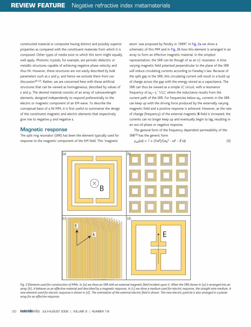
Magnetic responseThe split ring resonator (SRR) has been the element typically used for
response to the magnetic component of the EM field. This ‘magnetic
atom’ was proposed by Pendry in 19992. In Fig. 2a we show a
schematic of this MM and in Fig. 2b how this element is arranged in an
array to form an effective magnetic material. In the simplest
representation, the SRR can be though of as an LC resonator. A time
varying magnetic field polarized perpendicular to the plane of the SRR
will induce circulating currents according to Faraday’s law. Because of
the split gap in the SRR, this circulating current will result in a build up
of charge across the gap with the energy stored as a capacitance. The
SRR can thus be viewed as a simple LC circuit, with a resonance
frequency of ω0~� 1/LC, where the inductance results from the
current path of the SRR. For frequencies below ω0, currents in the SRR
can keep up with the driving force produced by the externally varying
magnetic field and a positive response is achieved. However, as the rate
of change (frequency) of the external magnetic BB-field is increased, the
currents can no longer keep up and eventually begin to lag, resulting in
an out-of-phase or negative response.
The general form of the frequency dependent permeability of the
SRR19 has the generic form
µeff(ω) = 1 + (Fω2)/(ω02 - ω2 - iΓω) (3)
Fig. 2 Elements used for construction of MMs. In (a) we show an SRR with an external magnetic field incident upon it. When the SRR shown in (a) is arranged into anarray (b), it behaves as an effective material and described by a magnetic response. In (c) we show a medium used for electric response, the straight wire medium. Anew element used for electric response is shown in (d). The orientation of the external electric field is shown. This new electric particle is also arranged in a planararray for an effective response.
REVIEW FEATURE Negative refractive index metamaterials
JULY-AUGUST 2006 | VOLUME 9 | NUMBER 7-830
(a)
(c) (d)
(b)
mt97_8p28_35.qxd 06/15/2006 15:25 Page 30
where F is a geometrical factor, ω0 is the resonance frequency, and Γ is
the resistive damping factor. Note that this magnetic response function
has real and imaginary frequency dependent parts. In Box 1, the
frequency dependent permeability of the SRR medium for typical
parameters is plotted, showing the frequency dependent resonant
form. If the ‘strength’ of the resonance is great enough and the
damping small enough, the SRR can yield a negative magnetic
response. The solid blue curve in Box 1 corresponds to the real part of
µ, which displays a region of negative values for this example.
Electric responseNaturally occurring materials that yield a negative response to the
electric component of light have been known for several decades. Any
metal below its plasma frequency (the frequency at which it becomes
transparent) yields negative values of the permittivity. This ε1 < 0
response results from the free electrons in the metal that screen
external EM radiation. But a bulk metal is not the only material that
exhibits negative electric response; a distributed array of conductors, or
even a grating on a conductor, can give the same result. Many decades
ago researchers fabricated structures having ε < 0 using arrays of
conducting wires and other unique shapes24-27. This technology was
recently reintroduced with a more physics-oriented understanding28,29.
Currently, variations of the wire lattice being used to create ε1 < 0
media include include straight wires, cut-wire segments, and loop
wires30. A straight wire medium is depicted in Fig. 2c. In addition, there
have been further advances in the development of electric MMs with
new designs analogous to the SRR being demonstrated (Fig. 2d)31,32.
The generic frequency dependent permittivity has the form
ε(ω) = 1 - (ωp2)/(ω2 - ω0
2 + iωΓ) (4)
where the plasma frequency, ωp2, is
ωp2 = 4π(ne2/m*) (5)
and n is the carrier density, e is the charge of an electron, and m* is
the effective mass of carriers. In naturally occurring materials, n refers
to the actual density of the charge carriers (usually electrons) and m*
to their effective mass. In a wire MM, n and m* are related to the
geometry of the lattice rather than the fundamental charge carriers,
giving MMs much greater flexibility than conventional materials.
Because the effective density can be reduced substantially by making
the wires thin, which has the added effect of increasing the effective
mass of the charge carriers, the effective plasma frequency can be
reduced by many orders of magnitude. In the context of NI MMs, the
wire lattice and its variants are a convenient means of achieving a
medium for which ε1 < 0. Because the plasma frequency can be tuned
by geometry, the region of moderately negative values of can be made
to occur at nearly any frequency range, from low RF to the optical.
Negative index metamaterialsHaving identified artificial structures that can separately provide ε1 < 0
and µ1 < 0, we can combine the two, according to Veselago’s
prescription, and construct a material with n < 0. But what, if anything,
is actually unusual about a NI material?
Veselago pointed out that a medium having an NI of refraction
would essentially add a new twist to virtually every EM phenomenon.
The phase velocity of a wave is reversed in NI materials; the Doppler
shift of a source relative to a receiver is reversed; Cerenkov radiation
emitted by a moving charged particle is in the backward rather than
the forward direction; radiation pressure is reversed to become a
radiation tension; converging lenses become diverging lenses and vice
versa. These are just some of the changes to basic EM phenomena that
would result in a NI material.
As intriguing as Veselago’s predictions were, naturally occurring
materials with a NI were not known at the time and his results
remained largely overlooked. However, in 2000 Smith et al.1 fabricated
an NI material using artificially constructed MMs. This NI MM
Negative refractive index metamaterials REVIEW FEATURE
JULY-AUGUST 2006 | VOLUME 9 | NUMBER 7-8 31
Box 1The index of refraction is a product of two complex functions, ε(ω) and
µ(ω). By representing the magnetic and electric response functions by
Lorentz oscillators (eq 4) in complex form we see that the index
squared is n2 = ε(ω)µ(ω) = reeiθermeiθm. The complex index of
refraction then becomes n = �(rermei(θe + θm)/2). Note the phase of the
index of refraction is simply the average of the phases of the magnetic
permeability and the electric permittivity, i.e. θn = (θe + θm)/2. This
indicates that the vector describing the index of refraction must lie in
quadrant II of the complex space. Thus finally we see that although
there is ambiguity in which sign to take for the real part of the index,
i.e. n = n1 + in2 = ± �εµ, when we consider causal functions it is
clear that the index of refraction is required to be negative n1 < 0.
mt97_8p28_35.qxd 06/15/2006 15:25 Page 31
combined a wire structure with ε1 < 0 and an SRR structure with µ1 <
0 over the same band of frequencies. That such a material could be
formed came as a surprise to many scientists; indeed some believed
that n was required by physical laws to be positive33-36. In fact, not
until a preponderance of theoretical and computational studies37-40
and experimental results41,42 were presented in favor of negative
refraction was the matter finally settled.
The first demonstration and confirmation of negative refraction was
performed in 2001 by Shelby et al.4. Negative refraction was
determined by a Snell’s Law experiment using a prism shaped MM
wedge, as shown in Fig. 3. A beam of microwave radiation incident on
the prism was observed to refract to the opposite side of the surface
normal, thus demonstrating negative refraction. For reference, the
same beam deflection experiment was performed using a Teflon prism
(positive index). The positive index sample deflected the beam to the
opposite side of the surface normal at an angle consistent with the
known index of the material. These initial results have now been
confirmed by numerous researchers, including Parazzoli et al.41 from
Boeing and Houck et al.42 from Massachusetts Institute of Technology.
With Veselago’s NI material finally a reality, and with numerous
experimental confirmations having established the validity of the MM
approach, researchers have taken up Veselago’s exploration of negative
refraction. An ever widening array of altered or new phenomena
associated with negative refraction are being discovered including,
e.g. the reversal of the Goos-Hanchen effect and enhanced diffraction.
In Fig. 4, we summarize some work extending MM response from
the initial discovery range – microwave (second row) – to both higher
and lower frequency ranges. Fig. 4 is arranged from the lowest
frequency in the top row to the highest frequencies in the bottom row.
There have been further extension of MMs to the NIR and near optical
frequencies, and these materials exhibit their response via a more
band-gap-like behavior43,44.
Perhaps one of the most striking predictions for MMs came in 2000,
when Pendry showed that a flat slab of NI material could produce a
focus with resolution exceeding the diffraction limit45. This was an
extraordinary prediction, since it required that the normally
exponentially decaying evanescent terms produced by a source would
actually be recovered in the image formed by the slab. All sources of
EM radiation possess both propagating components and components
that stay fixed, decaying rapidly away with distance from the source.
Mathematically, all EM sources can be expressed as a superposition of
propagating plane waves and exponentially decaying near-fields. These
exponentially decaying terms cannot be recovered by any known
positive index lens. Since the near field is responsible for conveying the
finest details of an object, their absence limits the resolution of positive
index optics to roughly λ/2 – the diffraction limit. However, Pendry
predicted that an NI lens would actually be able to recover the
exponentially decaying near-field components at the image, thereby
exhibiting resolution beyond the diffraction limit.
In the right panel of Fig. 1, we show how this focusing occurs for a
medium of n = -1. In the top portion of Fig. 1, a ray tracing diagram
shows how rays are focused by the slab. But the ray tracing picture
leaves out the evanescent, or exponentially decaying, components. The
diagram in the bottom right of Fig. 1 shows an evanescent component
that is, in some sense amplified, by the slab – growing exponentially as
a function of distance and then decaying exponentially until it reaches
its original magnitude at the image.
In 2004, Grbic and Eleftheriades46 demonstrated experimentally
subwavelength focusing with a NI material. This microwave experiment
was performed near 1 GHz and showed the ability of a planar left-
handed lens, with a relative refractive index of -1, to form images that
overcome the diffraction limit. The NI lens consists of a planar slab
constructed from a grid of printed metallic strips over a ground plane,
loaded with series capacitors and shunt inductors. The measured half-
power beamwidth of the point source image formed by the NI lens is
0.21 effective wavelengths, which is significantly narrower than that of
the diffraction-limited image corresponding to 0.36 wavelengths.
Natural materialsWhile the most familiar examples of NI materials have made use of
artificially patterned MMs, combinations of naturally occurring
REVIEW FEATURE Negative refractive index metamaterials
JULY-AUGUST 2006 | VOLUME 9 | NUMBER 7-832
Fig. 3 (a) An NI MM formed by SRRs and wires deposited lithographically onopposite sides of a standard circuit board. The height of the structure is 1 cm.(b) The power detected as a function of angle in a Snell’s law experimentperformed on a Teflon sample (blue curve) and an NI sample (red curve). (c) A schematic showing the geometry used to experimentally verify the NI ofrefraction.
(a)
(c)
(b)
mt97_8p28_35.qxd 06/15/2006 15:25 Page 32
Negative refractive index metamaterials REVIEW FEATURE
7. Yen, T. J., et al., Science (2004) 330033, 1494
8. Linden, S., et al., Science (2004) 330066, 1351
9. Zhang, S., et al., Phys. Rev. Lett. (2005) 9955, 137404
10. Enkrich, C., et al., Phys. Rev. Lett. (2005) 9955, 203901
11. Ramakrishna, S. A., (2006), private communication
12. Ramakrishna, S. A., Rep. Prog. Phys. (2005) 6688, 449
13. Focus Issue on Negative Refraction, New J. Phys. (2005) 77, 158, 191, 210, 220,223, 255
14. Focus Issue on Metamaterials, J. Opt. Soc. Am. B (2006) 2233, 386
15. Caloz, C., and Itoh, T., Electromagnetic Metamaterials: Transmission Line Theoryand Microwave Applications, Wiley-IEEE Press, New Jersey, USA, (2005)
16. Eleftheriades, G. V., and Balmain, K. G., Negative Refraction Metamaterials:Fundamental Principles and Applications, Wiley-IEEE Press, New Jersey, USA,(2005)
17. Engheta, N., and Ziolkowski, R. W., (eds.), Electromagnetic Metamaterials: Physicsand Engineering Explorations, Wiley-IEEE Press, New Jersey, USA, (2006)
18. Hecht, E., Optics, 4th edition, Addison-Wesley, Massachusetts, USA, (2001)
19. For a modern and complete investigation of refraction in EM-MMs see:Grzegorczyk, T. M., et al., IEEE Trans. Microw. Theory Tech. (2005) 5533, 1443
20. Foteinopoulou, S., et al., Phys. Rev. Lett. (2003) 9900, 107402
21. Parimi, P. V., et al., Nature (2003) 442266, 404
22. Luo, C., et al., Phys. Rev. B (2002) 6655, 201104
23. Material parameters are often only considered to depend upon the frequency,e.g. ε(ω) and µ(ω). However they are in general functions of both frequencyand the wave vector kk, ε(ω,kk) and µ(ω,kk). For small values of kk, they can stillbe approximated and described by ε(ω) and µ(ω). However, if the size of theobjects is about the same as the wavelength or larger, then there is asignificant dependence of the material parameters on kk and it is no longercorrect to describe the properties of the material by material parameters thatascribe a separate electric ε(ω) and magnetic µ(ω) dependence.
24. Bracewell, R. N., Wireless Eng. (1954) 3311, 320
25. Rotman, W., IRE Trans. Antennas Propag. (1962) AAPP1100, 82
26. Ulrich, R., Infrared Phys. (1966) 77, 37
27. Timusk, T., and Richards, P. L., Appl. Opt. (1981) 2200, 1355
28. Pendry, J. B., et al., Phys. Rev. Lett. (1996) 7766, 4773
29. Pendry, J. B., et al., J. Phys.: Condens. Matter (1998) 1100, 4785
30. Smith,D. R., et al., Appl. Phys. Lett. (1999) 7755, 1425
31. Schurig, D., et al., Appl. Phys. Lett. (2006) 8888, 041109
32. Padilla, W. J., et al., unpublished results
33. Burns, G., State Physics, Academic Press, USA (1985)
34. Valanju, P. M., et al., Phys. Rev. Lett. (2002) 8888, 187401
35. Garcia, N., and Nieto-Vesperinas, M., Opt. Lett. (2002) 2277, 885
36. Valanju, P. M., et al., Phys. Rev. Lett. (2003) 9900, 029704
37. Pacheco, J., et al., Phys. Rev. Lett. (2002) 8899, 257401
38. Loschialpo, P. F., et al., Phys. Rev. E (2003) 6677, 025602
39. Lu, W. T., et al., Phys. Rev. E (2004) 6699, 026604
40. Pendry, J. B., and Smith, D. R., Phys. Rev. Lett. (2003) 9900, 029703
41. Parazzoli, C. G., et al., Phys. Rev. Lett. (2003) 9900, 107401
42. Houck, A, A., et al., Phys. Rev. Lett. (2003) 9900, 137401
43. Zhang, S., et al., Phys. Rev. Lett. (2005) 9944, 37402
44. Shalaev, V. M., et al., Opt. Lett. (2005) 3300, 3356
45. Pendry, J. B., Phys. Rev. Lett. (2000) 8855, 3966
46. Grbic, A., and Eleftheriades, G. V., Phys. Rev. Lett. (2004) 9922, 117403
47. Holloway, C. L., et al., IEEE Trans. Antennas Propagat. (2003) 5511, 2596
48. Pimenov, A. et al., Phys. Rev. Lett. (2005) 9955, 24700949.
49. Chen, X. L., et al., Phys. Rev. B (2005) 7722, 113111
50. Chen, Y. F., et al., Phys. Rev. Lett. (2005) 9955, 067402
51. Wheeler, M. S., et al., Phys. Rev. B (2006) 7733, 045105
52. Padilla, W. J., et al., J. Opt. Soc. Am. B (2006) 2233, 404
53. Padilla, W. J., et al., Phys. Rev. Lett., (2006) 9966, 107401
54. Li, Z. Q., et al., Appl. Phys. Lett. (2005) 8866, 223506
55. Li, Z. Q., et al., Nano Lett. (2006) 66, 224
56. Driscoll, T., et al., Appl. Phys. Lett. (2006) 8888, 081101
57. Zhou, J., et al., Phys. Rev. Lett. (2005) 9955, 223902
Negative refractive index metamaterials REVIEW FEATURE


![QBE at a glance UK · QBE Insurance Group Limited A– [negative] A– [negative] bbb [negative] QBE Insurance (Europe) Limited A– [negative] a [negative] QBE Re (Europe) Limited](https://static.documents.pub/doc/80x56/5fa8e28b58047158406a3b4f/qbe-at-a-glance-uk-qbe-insurance-group-limited-aa-negative-aa-negative-bbb.jpg)


