Negative-Feedback Tone Control By P. J. BAXANDALL B.Sc.(Eng.) Independent Variation of Bass and Treble Without Switches he circuit to be described is the outcome of a prolonged investigation of tone-control circuits of the continuously adjustable type, and provides independent control of bass and treble response by means of two potentiometers, without the need for switches to change over from "lift" to "cut." Unusual features are the wide range of control available and the fact that a level response is obtained with both potentiometers at mid-setting. The treble-response curves are of almost constant shape, being shifted along the frequency axis when the control is operated, and there is practically no tendency for the curves to "flatten off" towards the upper limit of the audio range. The shape of the bass-response curves, though not constant, varies less than with most continuously adjustable circuits. T The "Virtual-Earth" Concept. The performance outlined above has been achieved by the use of a negative-feedback circuit instead of the more usual passive type of network 1,2 and it is desirable that the reader should become familiar with the "virtual-earth" concept 3 as applied to feedback amplifiers, before the operation of the tone-control circuit is considered in detail. The idea behind this concept is quite simple, and may be explained with reference to Fig. 1, in which all irrelevant details such as blocking capacitors, grid bias, etc., have been omitted, and in which V in and V out refer to a.c. components only. If the inputFirst Page resistor, R in in made equal to the feedback resistor, R fb , then the circuit becomes the well-known "see-saw" or "anode-follower" phase splitter 4,5 , and gives an output voltage which is 180 degrees out of phase with the input voltage and of slightly smaller magnitude. Now the a.c. voltage at the grid is equal to the output voltage divided by the valve gain, which may be 100 or more if the valve is a pentode, so that for many purposes the grid voltage is negligibly small in comparison with V in and V out . By thus neglecting the grid voltage, the following approximate relationships may be immediately deduced: — I in ≈ V in / R in (1) I fb ≈ V out / R fb (2) where I in and I fb are shown in Fig. 1. If grid current in the valve is also negligible, which is normally, the case, the application of Kirchhoff's first law (or just common sense!) to the junction of R in and R fb gives I in – I out = 0, so that, from (1) and (2): — ( V in / R in ) - ( V out / R fb ) ≈ 0 i.e, V out /V in ≈ - R fb /R in (3) When the grid voltage is neglected in this way, the grid is often called a "virtual-earth" point, and the use of the concept, though not necessary for dealing with a simple circuit such as Fig. 1, is 1 reproduced from pp. 402-405 Wireless World, October 1952 Fig. 1. Simple anode-follower circuit, illustrating the "virtual earth" concept.
Transcript
NegativeFeedback Tone ControlBy P. J. BAXANDALL
B.Sc.(Eng.)
Independent Variation of Bassand Treble Without Switches
he circuit to be described is the outcome of a prolonged investigation of tonecontrol
circuits of the continuously adjustable type, and provides independent control of bass and treble response by means of two potentiometers, without the need for switches to change over from "lift" to "cut." Unusual features are the wide range of control available and the fact that a level response is obtained with both potentiometers at midsetting. The trebleresponse curves are of almost constant shape, being shifted along the frequency axis when the control is operated, and there is practically no tendency for the curves to "flatten off" towards the upper limit of the audio range. The shape of the bassresponse curves, though not constant, varies less than with most continuously adjustable circuits.
T
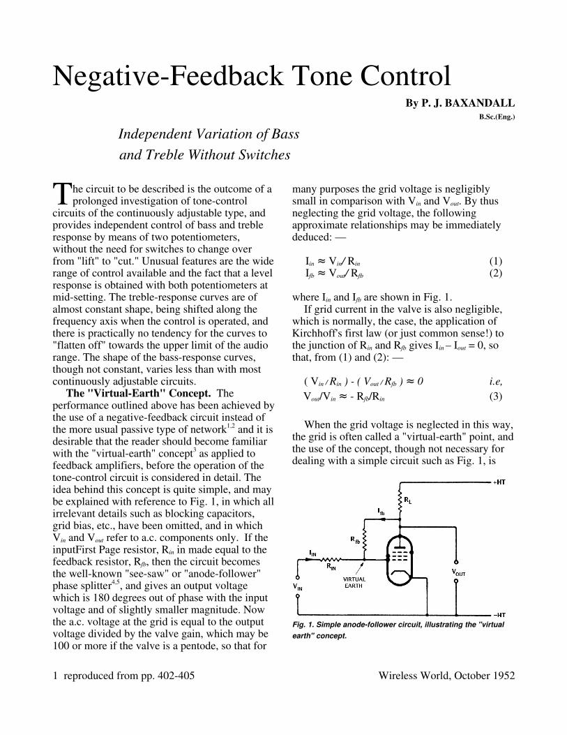
The "VirtualEarth" Concept. The performance outlined above has been achieved by the use of a negativefeedback circuit instead of the more usual passive type of network1,2 and it is desirable that the reader should become familiar with the "virtualearth" concept3 as applied to feedback amplifiers, before the operation of the tonecontrol circuit is considered in detail. The idea behind this concept is quite simple, and may be explained with reference to Fig. 1, in which all irrelevant details such as blocking capacitors, grid bias, etc., have been omitted, and in which Vin and Vout refer to a.c. components only. If the inputFirst Page resistor, Rin in made equal to the feedback resistor, Rfb, then the circuit becomes the wellknown "seesaw" or "anodefollower" phase splitter4,5, and gives an output voltage which is 180 degrees out of phase with the input voltage and of slightly smaller magnitude. Now the a.c. voltage at the grid is equal to the output voltage divided by the valve gain, which may be 100 or more if the valve is a pentode, so that for
many purposes the grid voltage is negligibly small in comparison with Vin and Vout. By thus neglecting the grid voltage, the following approximate relationships may be immediately deduced: —
Iin ≈ Vin/ Rin (1)Ifb ≈ Vout/ Rfb (2)
where Iin and Ifb are shown in Fig. 1.If grid current in the valve is also negligible,
which is normally, the case, the application of Kirchhoff's first law (or just common sense!) to the junction of Rin and Rfb gives Iin – Iout = 0, so that, from (1) and (2): —
When the grid voltage is neglected in this way, the grid is often called a "virtualearth" point, and the use of the concept, though not necessary for dealing with a simple circuit such as Fig. 1, is
1 reproduced from pp. 402405 Wireless World, October 1952
Fig. 1. Simple anodefollower circuit, illustrating the "virtual earth" concept.
found to be very helpful when dealing with more elaborate arrangements, and frequently gives one a far clearer physical picture of what is going on than does a straightforward mathematical analysis. The great practical value of this method of approach appears to have been first fully appreciated by Professor F. C. Williams, who introduced the name "virtual earth."
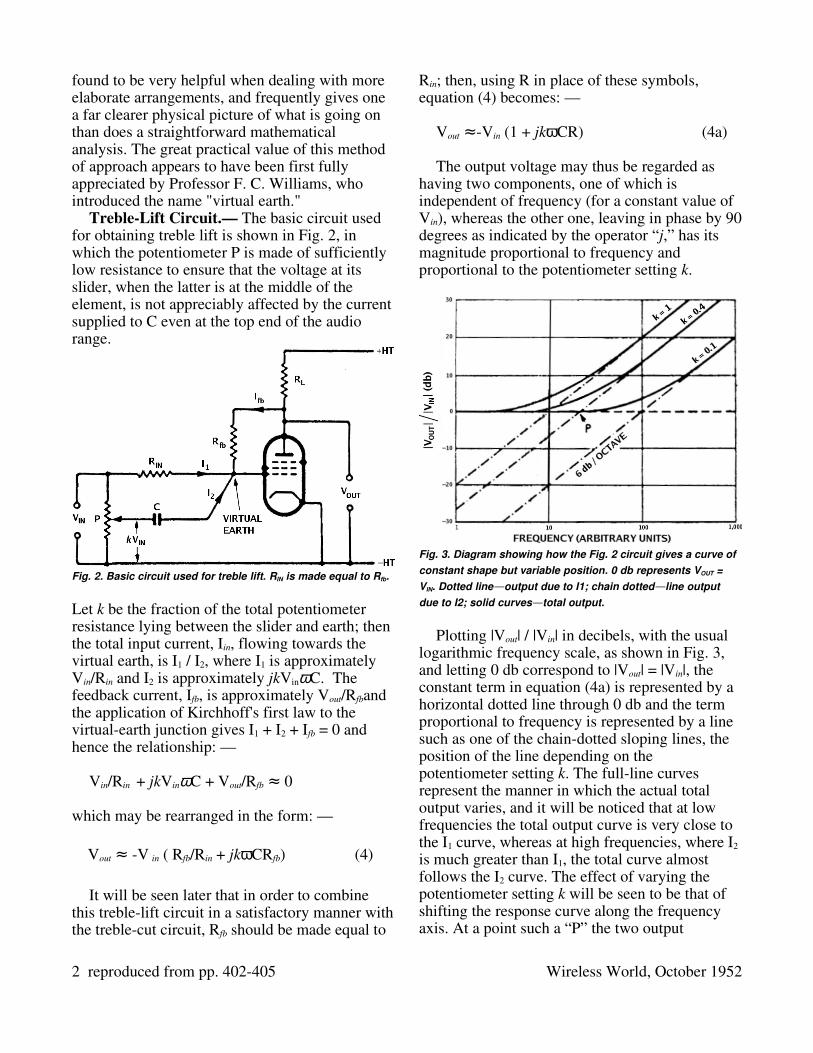
TrebleLift Circuit.— The basic circuit used for obtaining treble lift is shown in Fig. 2, in which the potentiometer P is made of sufficiently low resistance to ensure that the voltage at its slider, when the latter is at the middle of the element, is not appreciably affected by the current supplied to C even at the top end of the audio range.
Let k be the fraction of the total potentiometer resistance lying between the slider and earth; then the total input current, Iin, flowing towards the virtual earth, is I1 / I2, where I1 is approximately Vin/Rin and I2 is approximately jkVinωC. The feedback current, Ifb, is approximately Vout/Rfband the application of Kirchhoff's first law to the virtualearth junction gives I1 + I2 + Ifb = 0 and hence the relationship: —
Vin/Rin + jkVinωC + Vout/Rfb 0≈
which may be rearranged in the form: —
Vout V≈ in ( Rfb/Rin + jkωCRfb) (4)
It will be seen later that in order to combine this treblelift circuit in a satisfactory manner with the treblecut circuit, Rfb should be made equal to
Rin; then, using R in place of these symbols, equation (4) becomes: —
Vout ≈Vin (1 + jkωCR) (4a)
The output voltage may thus be regarded as having two components, one of which is independent of frequency (for a constant value of Vin), whereas the other one, leaving in phase by 90 degrees as indicated by the operator “j,” has its magnitude proportional to frequency and proportional to the potentiometer setting k.
Plotting |Vout| / |Vin| in decibels, with the usual logarithmic frequency scale, as shown in Fig. 3, and letting 0 db correspond to |Vout| = |Vin|, the constant term in equation (4a) is represented by a horizontal dotted line through 0 db and the term proportional to frequency is represented by a line such as one of the chaindotted sloping lines, the position of the line depending on the potentiometer setting k. The fullline curves represent the manner in which the actual total output varies, and it will be noticed that at low frequencies the total output curve is very close to the I1 curve, whereas at high frequencies, where I2 is much greater than I1, the total curve almost follows the I2 curve. The effect of varying the potentiometer setting k will be seen to be that of shifting the response curve along the frequency axis. At a point such a “P” the two output
2 reproduced from pp. 402405 Wireless World, October 1952
Fig. 2. Basic circuit used for treble lift. RIN is made equal to Rfb.
Fig. 3. Diagram showing how the Fig. 2 circuit gives a curve of constant shape but variable position. 0 db represents VOUT = VIN. Dotted line — output due to I1; chain dotted — line output due to I2; solid curves— total output.
components are of equal magnitude, and because of the 90degree phase angle between I2 and I1, the total output voltage will be 2 times that of each output component, or, in other words, the response will be 3db up.
TrebleCut Circuit.— For treble cut the basic circuit is shown in Fig. 4. The same method of analysis as was used for the treblelift circuit gives: —
Vin/Rin + Vout/Rfb + jkVoutωC 0≈
Hence
Vout V≈ in / ( Rin/Rfb + jkωCRin ) (5)
Making Rfb equal to Rin, as mentioned previously, and using R in place of these symbols, equation (5) becomes: —
Vout V≈ in / ( 1 + jkωCR ) (5a)
Comparing equation (5a) with equation (4a), it will be seen that, for the treblelift circuit, Vout is approximately equal to Vin multiplied by – (1 + jkωCR ), whereas for treblecut circuit Vout is approximately equal to Vin divided by – (1 + jkωCR ). Hence at any particular frequency and potentiometer setting the response of the Fig. 4 circuit will be “down” by the same number of decibels as that of Fig. 2 is “up,” so that the response curves of the two circuits, for each potentiometer setting k, will “mirror images” in
the 0 db line.Combined TrebleControl Circuit.— In
order to obtain treble lift or cut with singleknow control, the two circuits just described may be combined by using a centretapped potentiometer, which is available commercially in carbontrack form at a price only slightly in excess of that for an ordinary potentiometer. The centretap is earthed, on end of the element is connected to the input terminal, the other end is connect to the valve anode (via a coupling capacitor in practice), and the slider is connect to the capacitor C. Then when the slider is on the input side of the centretap, the circuit becomes that of Fig.2, and gives treble lift, whilst moving the slider to the anode side of the centretap gives the Fig. 4 circuit and provides treble cut. When the slider is at the centretap, the capacitor C is joined between virtual earth and actual earth, but the voltage between these two points is so small, when a highgain valve is used, that the current taken by the capacitor has a negligible effect on the frequency response within the working frequency range.
BassControl Circuit.— Fig. 5 shows the circuit used for bass lift and cut, omitting irrelevant details as before. In order to level response with the potentiometer at midsetting, and to allow the circuit to be easily combined with the treblecontrol circuit, R1 and C1 are made equal to R2 and C2. At middle and high frequencies the potentiometer is almost “shorted out” by the low reactances of C1 and C2, so that the circuit becomes almost the same as Fig. 1 with
3 reproduced from pp. 402405 Wireless World, October 1952
Fig. 4. Basic circuit used for treble cut. Rfb is made equal to RIN.
Fig. 5. Basic circuit used for bass lift and cut. R1=R2 and C1=C2.
Rin = Rfb, and a gain of approximately unity is obtained. As the frequency is lowered, the gain gradually rises or falls towards an asymptotic level determined by the potentiometer setting; and, as with the treblecontrol circuit, the response curves are approximately mirror images in the 0 db line for equal potentiometer displacements either side of the levelresponse setting. The amount in decibels, by which the gain of the Fig. 5 circuit departs from unity, is given approximately by: —
Lift, in db 20 log ( |Z≈ fb| / |Zin| ) (6)
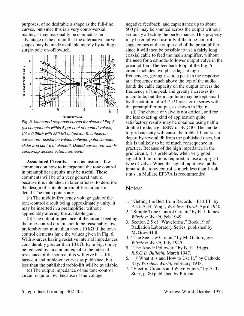
where |Zfb| and |Zin|are the moduli of the impedances between input terminal and grid and between anode and grid respectively. (Note, if an impedance calculated by means of the “j” notation comes out to R+jX, the modulus, or magnitude, is (R2 + X2); see reference 6.) Equation (6) may be used to calculate the response curves, point by point, for various potentiometer settings—a straightforward though timeconsuming process! The “crossover” effect noticeable with some of the measured bass curves shown in Fig. 8 may seem surprising at first, but it is quite genuine and equation (6) gives just the same result.
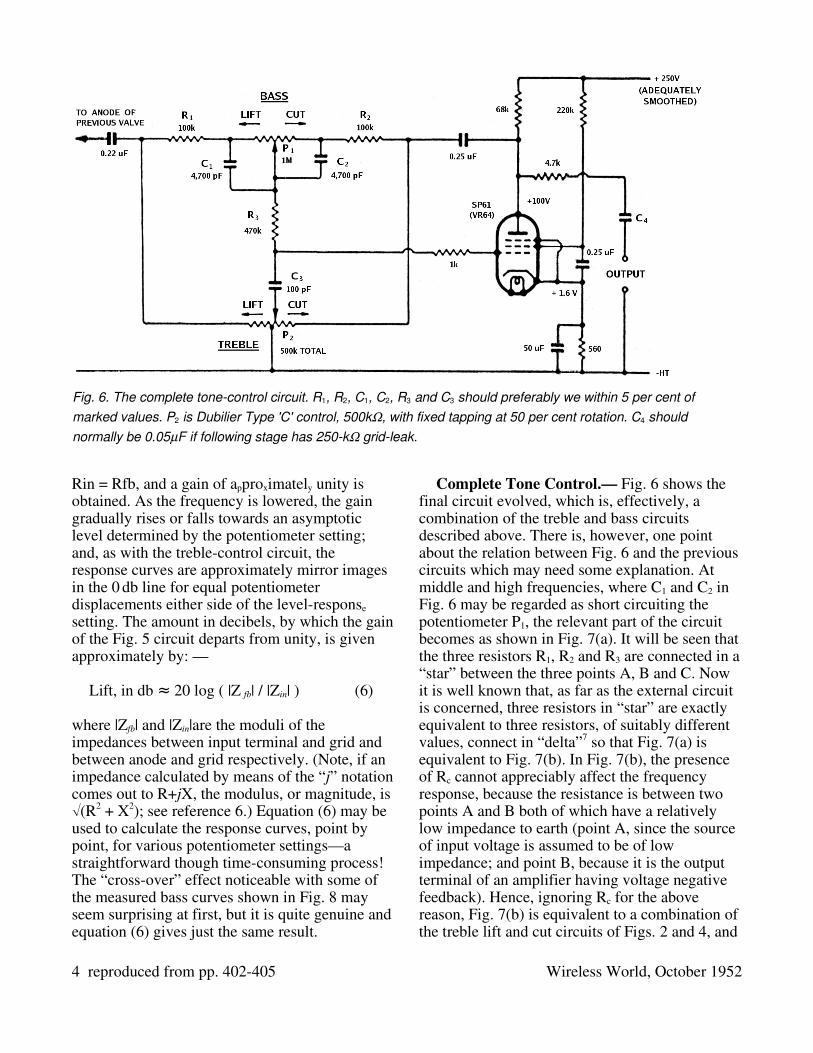
Complete Tone Control.— Fig. 6 shows the final circuit evolved, which is, effectively, a combination of the treble and bass circuits described above. There is, however, one point about the relation between Fig. 6 and the previous circuits which may need some explanation. At middle and high frequencies, where C1 and C2 in Fig. 6 may be regarded as short circuiting the potentiometer P1, the relevant part of the circuit becomes as shown in Fig. 7(a). It will be seen that the three resistors R1, R2 and R3 are connected in a “star” between the three points A, B and C. Now it is well known that, as far as the external circuit is concerned, three resistors in “star” are exactly equivalent to three resistors, of suitably different values, connect in “delta”7 so that Fig. 7(a) is equivalent to Fig. 7(b). In Fig. 7(b), the presence of Rc cannot appreciably affect the frequency response, because the resistance is between two points A and B both of which have a relatively low impedance to earth (point A, since the source of input voltage is assumed to be of low impedance; and point B, because it is the output terminal of an amplifier having voltage negative feedback). Hence, ignoring Rc for the above reason, Fig. 7(b) is equivalent to a combination of the treble lift and cut circuits of Figs. 2 and 4, and
4 reproduced from pp. 402405 Wireless World, October 1952
Fig. 6. The complete tonecontrol circuit. R1, R2, C1, C2, R3 and C3 should preferably we within 5 per cent of marked values. P2 is Dubilier Type 'C' control, 500k, with fixed tapping at 50 per cent rotation. C4 should normally be 0.05F if following stage has 250k gridleak.
therefore Fig. 7(a) is also equivalent to this combination. The relation between star and delta networks is such that if R1 is made equal to R2 in Fig. 6, which is essential for giving “mirror image” lift and cut curves, then Ra and Rb in Fig. 7(b) are each equal to R1 + 2R3. The important practical result of this reasoning is that the treble response will 3db up or down, at fulllift of fullcut settings respectively, at the frequency for which the reactance of C3 in Fig. 6 is numerically equal to R1 + 2R3.
The values of the main components in Fig. 6 were decided as follows. P1 was fixed at 1 MΩ, this being considered the highest really desirable value for a carbon potentiometer. To give about 20 db asymptotic bass lift and cut, the nearest standard value for R1 and R2 was 100 kΩ. A suitable compromise for C3 was 100 pF, on the grounds that, to obtain a result in accordance with calculation, the value should be large in relation to likely wiring strays, but that too large a value would result in an undesirably low impedance begin thrown across the source of Vin. The value of P2 then had to be chosen so that, with the slider half way between the centretap and one end the effective internal resistance of the potentiometer, regarding it as a generator feeding C3 should be not more than say, half the reactance of C3 at 10 kc/s. Now the reactance of 100 pF at 10 kc/s is approximately 160 kΩ, and using a total value of 500 kΩ for P2, each half is 250 kΩ and the
internal generator resistance referred to is thus 250/4, i.e., 62.5 kΩ, which being less than half the capacitance reactance, was regarded as satisfactory. The values of C1 and C2, which must always be equal, were then chosen to position the bass curves at an appropriate part of the frequency scale, and R3 was selected to do the same for the treble curves.
A highslope pentode valve was employed in order to obtain a high gain between grid and anode, thereby ensuring close agreement between the measured results and those given by the approximate analysis presented above. A further reason for using a highslope pentode was that, in a feedback circuit such as this one, where the gain with feedback is almost independent of the actual valve gain, the nonlinearity distortion would have been greater if a lowslope pentode or a triode had been used—an important fact which does not seem to be sufficiently widely known.
The circuit as shown in Fig. 6 will deliver an output of 4V r.m.s without introducing more than 0.1 per cent total harmonic distortion, for any signal frequency up to 5 kc/s and at any setting of the potentiometers.
The fullline curves in Fig. 8 show the measured performance obtained with the circuit of Fig. 6. The dotted curves were obtained with the same circuit, except that the centretap of P2 was disconnected from earth. The writer does not regard the dotted curves as being, for normal
5 reproduced from pp. 402405 Wireless World, October 1952
Fig. 7. (a) At middle and high frequencies, the resistors R1, R2 and R3 of Fig. 6 are effectively connected in “star”; (b) shows the equivalent “delta” network.
purposes, of so desirable a shape as the fullline curves, but since this is a very controversial matter, it may reasonably be claimed as an advantage of the circuit that the alternative curve shapes may be made available merely by adding a singlepole onoff switch.
Associated Circuits.—In conclusion, a few comments on how to incorporate the tone control in preamplifier circuits may be useful. These comments will be of a very general nature, because it is intended, in later articles, to describe the design of suitable preamplifier circuits in detail. The main points are:—
(a) The middlefrequency voltage gain of the tonecontrol circuit being approximately unity, it may be inserted in a preamplifier without appreciably altering the available gain.
(b) The output impedance of the circuit feeding the tonecontrol circuit should be reasonably low, preferably not more than about 10 kΩ if the tonecontrol elements have the values given in Fig. 6. With sources having resistive internal impedances considerably greater than 10 kΩ, R1 in Fig. 6 may be reduced by an amount equal to the internal resistance of the source; this will give basslift, basscut and treblecut curves as published, but less than the published treblelift will be available.
(c) The output impedance of the tonecontrol circuit is quite low, because of the voltage
negative feedback, and capacitance up to about 500 pF may be shunted across the output without seriously affecting the performance. This property may be employed usefully if the tonecontrol stage comes at the output end of the preamplifier, since it will then be possible to use a fairly long coaxial cable to feed the main amplifier, without the need for a cathodefollower output valve in the preamplifier. The feedback loop of the Fig. 6 circuit includes two phase lags at high frequencies, giving rise to a peak in the response at a frequency much above the top of the audio band; the cable capacity on the output lowers the frequency of the peak and greatly increases its magnitude, but the magnitude may be kept small by the addition of a 4.7 kΩ resistor in series with the preamplifier output, as shown in Fig. 6.
(d) The choice of valve is not critical, and for the less exacting kind of application quite satisfactory results may be obtained using half a double triode, e.g., 6SN7 or BCC40. The anodetogrid capacity will cause the treblelift curves to depart by several db from the published ones, but this is unlikely to be of much consequence in practice. Because of the high impedance in the grid circuit, it is preferable, when very good signaltohum ratio is required, to use a topgrid type of valve. When the signal input level at the input to the tonecontrol is much less than 1 volt r.m.s., a Mullard EF37A is recommended.
Notes:
1. “Getting the Best from Records—Part III” by P. G. A. H. Voigt, Wireless World, April 1940.
2. “Simple Tone Control Circuit” by E. J. James, Wireless World, Feb 1949.
3. Section 2.5 of “Waveforms,” Book 19 of Radiation Laboratory Series, published by McGrawHill.
4. “The Seesaw Circuit,” by M. G. Scroggie, Wireless World, July 1945.
5. “The Anode Follower,” by B. H. Briggs, R.S.G.B. Bulletin, March 1947.
6. “ 'j' What it is and How to Use It,” by Cathode Ray, Wireless World, February 1948.
7. “Electric Circuits and Wave Filters,” by A. T. Starr, p. 80 published by Pitman.
6 reproduced from pp. 402405 Wireless World, October 1952
Fig. 8. Measured response curves for circuit of Fig. 6 (all components within 5 per cent of marked values; C4 = 0.25F with 250k output load). Labels on curves are resistance values between potentiometer slider and centre of element. Dotted curves are with P2
centretap disconnected from earth.
The following erratum appeared in Wireless World, November 1952:
“Negativefeedback Tone Control”Owing to an omission from the inscription to
Fig. 6 of the above article in the October issue, some ambiguity has arisen regarding the law of the potentiometers P1 and P2, though from the curves of Fig. 8 it is implicit that they are linear. The relevant part of the inscription to Fig. 6 should read “P1 and P2 must both have linear elements. P2 is Dubilier Type 'C' control, 500 kΩ, with fixed tapping at 50 per cent rotation.”
The dotted curves of Fig. 8 with P2 centre tap disconnected were measured with an input attenuator forming a return path for the grid. When the filter is fed via a capacitor (as in Fig. 6), and the modified response is required, the grid may be “tied down” to earth by a highresistance leak, but the preferred method is to use two 330 kΩ resistors, one from the lefthand and the other from the righthand end of P2 to earth, the central tap being disconnected. The lower value of resistors avoids possible trouble from leaky coupling capacitors, and/or slight grid current, without appreciably affecting feedback and nonlinearity distortion.
Thanks to Danny Noordzy for pointing out the existance of this erratum and subsequently sending me a scan of the document.
7 reproduced from pp. 402405 Wireless World, October 1952