Vol. 1 No. 4 October – December 2014 ISSN: 2348-6007 NEHRU INTERNATIONAL JOURNAL OF ENGINEERING & TECHNOLOGY Nehru Institute of Engineering and Technology (Approved by AICTE, New Delhi & Affiliated to Anna university) ‘Nehru Gardens’, Thirumalayampalayam, Coimbatore -641 105. Tamilnadu, India E-mail: [email protected]Web: www.nehrucolleges.com
Transcript
Vol. 1 No. 4 October – December 2014 ISSN: 2348-6007
NEHRU INTERNATIONAL JOURNAL OF ENGINEERING & TECHNOLOGY
Nehru Institute of Engineering and Technology (Approved by AICTE, New Delhi & Affiliated to Anna university)
1. Miniaturized Ultra Wide Band Bandpass Filter With Dual NotchFrequncies Using Microstrip DesignV.Reji & K.Srisabarimani
1-5
2. Searching Information in Spatial DatabaseD.Lakshminarayanan
6-12
3. High Stable Power Aware Multicast Routing with Cross LayerEnchancement in ManetS. Sriuthhra, L. Gomathi, G. Priyadharshini, P.Elakkiya &Mr.M.S. Gowtham
13-20
4. Iris Biometrics for Embedded SystemsG.Sathya, S.Arun & M.Dharani
21-25
5. True Random Based Differential Power Analysis CountermeasureCircuit for an AES EngineS. Saravanakumar & Prof. M. Shanthi
26-31
6. Energy Efficient ECO Friendly Refreginerator Cum OvenR.Aarthika, P.T.Adharsh, G.Arun, V.ArunkumarDr.M.Sreedhar
32-36
7. Smart Power Genaration And Conservation from Overhead, TanksR.Jawahar, M.Dhivya, Ebinzachariavarghese, K.Menaka &Mr.S.Ashwanth. ME
37-40
8. Non-Conventional Power Generation from Human DroppingsT.Anitha, J.Anjapulikannan, D.Karthikeyan, S.Girinath &MR.K.Rajaram
41-46
9. Numerical Analysis of Mould Filling and Gating Design forAluminium Mould CastingsSiva. P & Ragoth Singh. R
47-54
10. Driving Assistance and Accident Aversion System Using ProximitySensorsRajagopalan Shravan, Samuel Paul Peter & Shri Harish
55-59
11. Reduction of Cost by Replacing Spring Instead of UsingTorsion Bar in the Tailgate MechanismGowtham Munipandi M T & Samuel M
60-62
12. Embedded Based Air Pollution Monitoring in Foundry IndustriesP. Kumar & K. Nagarajan
63-67
Vol. 1 No.4 Oct-Dec 2014 ISSN: 2348-6007
1
MINIATURIZED ULTRA WIDE BAND BANDPASS FILTER WITH DUALNOTCH FREQUNCIES USING MICROSTRIP DESIGN
ABSTRACT:In this paper, a miniaturized version of Ultra Wide Band (UWB) BandPass Filter with
dual notch frequencies is presented. The Ultra Wide Band Pass Filter is formed by thecombination of a Low Pass Filter(LPF) and a High Pass Filter(HPF). The Wide Pass band is
specifications is achieved by Microstrip Line Design. The dual frequencies notches are at 5.75GHz and 8.05 GHz obtained by embedding two open circuit stubs on the main Microstrip Line.The equivalent circuit of the proposed filter is presented in the paper. The filter design is tested
and simulated using the Integrated Electronic Simulation (IE3D) software and the output graphsare also presented.
Index Terms — Ultra Wide Band, LPF, HPF notch band, Band Pass Filter.
1. INTRODUCTIONWith the announcement of the
unlicensed band (3.1 GHz – 10.6 GHz) bythe Federal Communication Commission(FCC) there has been enormous researchtaking place to utilize this frequency band.This is due to the numerous applications thatutilize this frequency band such assurveillance systems, medical imagingsystem, pulse communication, groundpenetration radar, etc. But this unlicensedband of frequencies interferers with twolicensed frequencies namely 5.75 GHz and8.05GHz which is used in Wireless LAN andSatellite Communication respectively. Thuswe need a UWB Band Pass Filter [1],[2]which has the ability of accepted theunlicensed band and rejecting the licensedfrequencies so that it do not interfere with theapplications of unlicensed band.
In this paper we have used theChebyshev Filter design for both LPF andHPF.
Chebyshev filters [2] have the propertythat they minimize the error between theidealized and the actual filter characteristicover the range of the filter,but with ripples inthe passband.Cheybyshev’s filter is a betteroption than the Butterworth Filter because itgives stepper attenuation in the stop band andthus more inclined towards the idealcharacteristics. Then as the waveguide formof LPF and HPF cannot be realised sincewaveguides are basically high-pass lines andthus we form the Microstrip configuration.The proposed UWB[8] filter is realised usingsubstrate of dielectric constant 2.2 andsubstrate height 0.787 mm. The rest of thepaper contains the design procedure of thefilter followed by the results and discussions.
2. FILTER DESIGNThe Ultra Wide Band(UWB) Bandpass
Filter is designed for the frequency of 3 GHzto 11 GHz. To remove the two specifiedfrequencies such as 5.75 GHz and 8.05GHz
Vol. 1 No.4 Oct-Dec 2014 ISSN: 2348-6007
2
we use two individual open circuit stubs.These are the two notches used for removing the two frequencies to perturb WLAN and satellite signal interference. The filter design chosen is the combination of LPF and HPF in top and bottom side of microstrip structure shown in fig 1.
Figure.1 BPF with two notches (top view) 2.1 Lowpass Filter Design The UWB filter is formed by the combination of the both the LPF and HPF with different cut – off frequencies. Filter designs beyond 500 MHz are difficult to realize with discrete components because the wavelength becomes comparable with the physical filter element dimensions[7][8], resulting in various losses. Thus, to arrive at practical filters, the lumped components are converted into distributed element realizations. In the rest of this section the detailed design process of each of the individuals sections is described. 1. Norma diagram 2. Simuation diagram
Figure.2 Low pass Filter attenuation in dB A Chebyshev’s LPF[4],[5] is designed for the cut off frequency of 11GHz shown in fig 2. The ripple in the Chebyshev’s response is considered 0.5 dB. By the Chebyshev’s LPF design the order of the filter is obtained as 5 thus indication the existence of 5 components in the filter. The Chebyshev filter design is chosen to get steeper attenuation in the stop band and equal ripples
in stop and pass band. A ‘Pi ( ‘type LPF is
considered with 3 capacitors and 2 inductors. To calculate the value of each component of the filter, two important transformations, namely, Impedance and Frequency Transformations is used. Further, these low frequency components are converted to distributed elements for the Microstrip design. The LPF attenuation response is given in Fig.2 and the Microstrip LPF design is shown in the Fig. 3. The design equation is[2]
εeff=(εr+1)/2+(εr-1)/2(1+12h/w)-1/2
Figure.3 Microstrip LPF design
(Bottom view)
Attenuation/dB
ω
0
11
3
10
20
30
40
Vol. 1 No.4 Oct-Dec 2014 ISSN: 2348-6007
3
2.3 HighPass Filter Design To accomplish the conversion from lumped and distributed circuit designs, Richards proposed a special transformation that allows open and short circuit transmission line segments to emulate the inductive and capacitive behaviour of the discrete components. The input impedance of a short circuit transmission line of characteristic impedance Zo is purely reactive. Zin = j Zo tan (βl) = j Zo tan Θ Here the electric length Θ can be rewritten in such a way as to make the frequency behavior explicit. If we pick the line length to be λo/8 at a particular reference frequency fo = Vp/λo the electric length becomes Θ = (П/4)Ω On substituting we get jωL = j Zo tan ((П/4) Ω) = SZo Similarly jωC = j Yo tan ((П/4) Ω) = SYo Here S= j tan ((П/4) Ω) is Richards transform. The design is implemented based on the two conditions, W/h<=1 and W/h>=1 and based on that the εeff and impedance value is calculated. These values help in calculating the individual strip lengths. The individual capacitive and inductive lengths are calculated to get the overall size of the filter. Thus the overall size of LPF filter turns out to be 25.347 mm or 2.5347 cm. The Microstrip design helps in achieving the miniaturized version of the filter. Thus the above mentioned LPF is designed for the cut off frequency of 11 GHz and with and overall size of 2.5347 cm.
ω
Attenuation/d0
3
3
1
2
3
4
Figure.4 High pass Filter attenuation in dB
To restrict the frequencies below 3 GHz, a High Pass Filter (HPF) is designed with cut off frequency of 3 GHz using Chebyshev design. The filter is designed for 0.2 dB ripple. The Chebyshev HPF design leads to the order of filter as 5 indicating 5 filter
components shown in fig5.A ‘Pi ( ‘type
HPF is considered with 2 capacitors and 3 inductors. The conversion of the lumped elements into distributed elements in HPF[5] is done using namely two transformations: Richards Transformation and Kuroda’s Identities. To accomplish this conversion Richards Transformation allows open- and short-circuit transmission line segments to emulate the inductive and capacitive behavior of the discrete components. Now the series inductance implemented by a short-circuit transmission line segment is more complicated to realize than a shunt stub line. Thus Kuroda’s Identity converts the series stub lines to the shunt stubs. The transformed filter after the Richards and Kuroda’s Identity is shown below in fig5:
Figure .5 High pass Filter design
Using Stubs
Vol. 1 No.4 Oct-Dec 2014 ISSN: 2348-6007
4
Now the elements obtained above are de-normalized and equivalent microstrips are obtained. De-normalizing involves scaling the unit element to the 50Ω input and output impedances and computing the length of the lines. Using λ0/8 = vp/(8fc ), the length is found out to be l =λ0/8 = 7.5 mm where fc = 3GHz. The final design of the HPF is shown below in fig. 6. Thus the overall length of the HFP comes out to be 33.65 mm or 3.3365 cm. Now with the UWB[6],[7] filter design we have achieved selecting frequencies from 3 – 11 GHz. Now the stubs are designed to remove the two frequencies 5.75 GHz and 8.05 GHz. The length of the stubs is chosen to be λ0/8 to suit our miniaturized model. The length of the stubs for both frequencies are .91mmand 7.5.
Figure .6 Micro strip HPF design
Figure.7 HPF response at 3GHz
3. RESULT AND DISCUSSION
Figure.8 Band Pass Filter Band Pass Filter with notch response Simulated and measured scattering parameters are described in Fig 2, 7 with good agreement. Referring to Fig. 8, the fabricated UWB BPF has a pass-band from 3-11 GHz. Two notched bands with insertion losses over 2 dB with ripple 0.5dB at 5.9 and 8.0 GHz are achieved. For the two sharp notches, the measured 3 dB fractional bandwidths (FBWs) are 4.6% at 5.9 GHz and 3.0% at 8.0 GHz, respectively. It should be noted that we can reduce the distance to further enhance the rejection level in the notched bands. 4. CONCLUSION A new microstrip UWB BPF with two sharp notches by combining lowpass and highpass filter has been proposed in this paper. The lowpass filter is designed by step impedance method and highpass filter is designed by short circuited stub method with order of filter five. The proposed filter is useful for modern UWB wireless communication systems due to its simple structure, compact size, and good performance.
Vol. 1 No.4 Oct-Dec 2014 ISSN: 2348-6007
5
REFERENCES 1. Pankaj Sarkar,Rowda Ghatak” Compact
UWB Bandpass Filter with Dual notch bands” IEEE microwave and Wireless components letters Vol22 Sep 2012
2. Reinhold Ludwig “RF design” 3. G. L. Matthaei, L. Young and E. M. T.
Jones, “Micro- wave Filters, Impedance Matching Networks and Cou- pling Structures,” McGraw-Hill, New York, 1964.
4. H. Ishida and K. Araki, “Design and Analysis of UWB Band Pass Filter with Ring Filter,” IEEE MTT-S Interna-tional
Microwave Symposium Digest, Fort Worth, 6-11 June 2004, pp. 1307-1310.
5. S.Sun and L.Zhu “Multimode resonator based band pass filter” IEEE Micro,Mag,Vol10, No 2 PP 88-98, apr,2009
6. W.-S. Chang and C.-Y. Chang,
“Analytical Design of Microstrip Short-Circuit Terminated Stepped-Impedance Resonator Dual-Band Filters,” IEEE Transactions on
Mi-crowave Theory and Techniques, Vol. 59, No. 7, 2011, pp. 1730-1739. doi:10.1109/TMTT.2011.2132140
7. K. Li, D. Kurita and T. Matsui, “UWB Bandpass Filters with Multi Notched Bands,” 36th European Microwave
Conference Proceedings, Manchester, 10-15 September 2006, pp. 591- 594.
8. H. Shaman and J.-S. Hong, “Ultra-Wideband (UWB) Band- pass Filter with Embedded Band Notch Structures,” IEEE Microwave and
D.Lakshminarayanan University College of Engineering, Tiruchirappali.
ABSTRACT This works mainly concentrated on fairly accurate string look for in spatial databases.
The query used to search a particular string in spatial database is knownas Spatial Approximate String (SAS) query. This query is used inboth Euclidean Space and in the Road Networks[2],[3].
The MHR-Tree is used in Euclidean Space to get the approximated strings listed from the spatial database. The index node u of MHR-Tree maintains min-wise signatures of the strings. Under the
index node u, the signatures are in the form of concise representation of all q-grams. The pruning method is used for cutting back of such signatures, according to the set similarity between the
given string and the q-grams of sub-trees of u. Some of new techniques added into the query of the MHR-Tree.
Index Terms— SAS, q-grams, MHR-Tree.
1. INTRODUCTION A spatial database is defined as a database which is able to store and query the multidimensional data objects such as points, lines, regions, spots and other objects with set of spatial extent, using data structures and indexing methods that take care of the different spatial belongings of each object. With the popularity of geographic services such as Google Earth, Maps, queries in spatial databases have become more and more important in recent years. Past spatial queries such as nearest neighbor queries, range queries & spatial joins associated with textual data, queries on spatial items are origination to receive significant attention from the spatial database researchers, which leads to a hunt called Spatial Approximate String Search. Spatial database manages geometric objects and coordinates such as points, line, rectangles. In reality, a spatial object often comes with a text description like the list of services of a hotel, facilities of a hotel, the outpatient
specialties of a hospital, and menu of a restaurant. In many applications, users need to search with both spatial as well as textual predicates. 2. BACKGROUND 2.1. Problem Formulation The R-tree is a dynamic index structure [1] for spatial database which supports spatial operations such as intersection, range and nearest search. By splitting the multidimensional data into nested, and possibly overlapping, bounding boxes or minimum bounding rectangle (MBR). It has smaller structure nodes for storing the strings related to spatial. It could suffer from unnecessary node visits which lead to higher I/O cost and string similarity comparisons which lead to higher CPU cost. For an extreme example, considering a query in Euclidean Space with a query string that does not have any related strings within its query
range, A = ∅. So ideally, this query should
Vol. 1 No.4 Oct-Dec 2014 ISSN: 2348-6007
7
bring upon itself a minimum of query cost.To avoid unnecessary searches throughout the tree, there is a need for indexing methodology to find whether the given query string available or not in the dataset at root level itself. For that, the IR-Tree was proposed to avoid the unnecessary searches which reduce the CPU as well as I/O costs as minimum. To the best of our knowledge, no approach currently exists that supports processing of spatial keyword queries on road networks [2],[3]. A solution to this problem is complex, and requires efficient index structures for the spatial and textual part of the spatio-textual objects, as well as an efficient representation of the road network that supports exact computation of the network distance. The IR-Tree is proposed. The inverted file keeps an index of whether a given term can be found in the sub-tree or not. As for the road network representation, a flexible road network framework that supports processing of common spatial queries such as range and k-Nearest Neighbors (kNN), as well as exact computation of the network distance from a query location to the spatial objects. The framework is based on the network expansion principle, which is similar to the operations of Dijkstra’s algorithm; the edges of a network are gradually expanded from a query point, reporting spatial objects as they are encountered during the expansion. Unluckily, this framework does not support spatial keyword queries. Other issues are: extensive computation to detect and prune false positives when searching in the IR-Tree for spatio-texsual objects and also increased runtime and I/O costs.To avoid false hits throughout the tree, there is a need for inverted file methodology to find whether the given query string is available or not in the dataset at root level itself.
For that, the IR2-Tree was proposed to avoid the false hits which reduce the I/O cost as minimum. There are an array of functions to measure the similarity between strings, including edit distance (Levenshtein distance), Jaccard similarity, and Cosine similarity. Several algorithms have focused on approximate string queries using the edit distance function, mainly due to its pertinent in many scenarios. The idea of “grams” [4] has been broadly used in these algorithms. But there is a dilemma in choosing the gram length q: If it increased q, there could be fewer strings sharing a gram, resulting in shorter lists, and less time to access them. On the other hand, it may also reduce the lower bound on the number of common grams shared by similar strings, causing more false positives after accessing the lists. There was no common length of q-grams for a single string. But here we can decide the length of the q-gram. The R-tree is the tree based on the index for spatial queries, and the inverted file is the most efficient index for retrieving the text related information. Inverted file-R*-Tree (IF-R*) and R*- Tree-inverted file (R*-IF) are two geo-textual indices that combine the R*-Tree and inverted file. KR*-Tree [5] is nothing but Keyword R*-tree. Each node of the KR*-tree is virtually augmented with the set of keywords that appear in the sub-tree rooted at the node. The nodes of the KR*-tree are organized into inverted lists as are the objects. This may help to prune the tree nodes under which objects do not contain query keywords in query processing stage at any cost. Spatial join queries [6] which are different from selection queries (range and nearest neighbor) that are single-scan, characterized as multiple-scan queries, because objects may have to be accessed more than once. Therefore, this type of query poses increased requirements for efficient
Vol. 1 No.4 Oct-Dec 2014 ISSN: 2348-6007
8
query processing. If their MBRs do not intersect, then further examination of the corresponding sub-trees can be avoided. Otherwise, the algorithm continues recursively to the entries of the sub-trees. This presents a search pruning criterion that capitalizes on the clustering properties of the R-tree. The CPU-time Tuning is the basic form of this technique. Each node entry is examined against all entries of the other node. For this reason, two optimizations are proposed that are 1) Restricting the Search Space and 2) Spatial Sorting and Plane Sweep. The n-gram inverted index has two advantages [7] that are language-neutral and error-tolerant. So that it can be used widely in string similarity findings and resemblance of two strings. But it has an issue that, the larger size. From past decades, the performance of string search in spatial databases is searching effective methods to produce more strings exactly. For that, there are lot and lot of methods, algorithms, researches going on in order to produce good results. From existing system, there are many algorithms, concepts to search strings in spatial related data. But everyone is having small amount of inconvenience in performance, cost, efficiency or result producing etc. The following lists are comparative studies of different algorithms which were used previously for searching spatial related information. • It is difficult to find the string similarity
and finding the similarity is a costly operation also.
• R-Tree used in Euclidean Space leads to Higher I/O Cost and Higher CPU Cost, so the Complexity is also high.
• Dijkstra’s algorithm used in Road Networks lead to less performance when the query range enlarges and/or data on the network increases.
• Difficulty in finding the selectivity estimation for Road Networks.
2.2. Objectives In order to get exact strings from a non exact keyword the following processes should be formulized.
• Calculating q-grams.
• Constructing MHR-tree with some modifications.
• Remove the redundant q-grams.
• Insert a pointer for each q-grams which are come in repeated manner.
• Suggests more number of strings accurately.
3. MHR-TREE FORMULARION In previous case, the string to be searched was given by the user in exact manner. Then the matched string will be suggested. The following figure shows the process of existing system.
3.1. Proposed System of Euclidean Space Now-a-days the keyword search is the important one in which the misspelled keywords have been placed in the search box. Without internet the users can’t get the spatial information as their needs. So the data related to the spatial plays very big roles in
Fig: 3.1. Existing System
Get exact string to be searched in spatial database
No matching
Suggests the strings available in spatial database
Match the string with spatial database Spatial
Database
True
False
Vol. 1 No.4 Oct-Dec 2014 ISSN: 2348-6007
9
today’s scenarios. The approximate string search could be needed when the users have a nebulous search condition or simply a spelling error when submitting the query, or the strings in the spatial database contain some degree of error or ambiguity. So we have to list out the exact strings even though the string to be searched given by the user is wrong. For example, the user is searching the string “San Francisco” with the query string of “son”. The query string given by the user “son” is a misspelled one. But the suggested string will contain only the strings with “son” whether prefixed, suffixed, or part of the candidate strings. But the user needs to get the details about the “San Francisco”. Consider another example with homophonic words such as flour and flower. These keywords are not misspelled keywords. But the both strings should be suggested to the user when the user may give any one of these queries. This is the proposed system in which the goal will reached in an efficient manner. For that, there is lot of ideas proposed to search more information regarding to the spatial related data. The followings are the important processes to be considered in order to get exact strings from a given query string which wrongly typed by the user. It is very important to know the following processes:
• Edit distance calculation
• q-grams
• Min-wise signature
3.2. Edit Distance – a glance After that it should be known that what the q-gram is. The q-gram refers to a sequence of letters, q letters long, from a given keyword for example. Consider q=2. university = = > un ni iv veerrssi it ty temple = = >teemmppl le The process of edit distance calculation is costly operation.
A new idea is introduced to work with the special case at the first and the last characters of σ, that have fewer than q characters, one may introduce special characters, which are # and $, which are not in given string. The first q-gram has length of q in which the last character is the first character of the given string prefixed with $ symbol. The last q-gram has the length of q in which the first character is the last character of the given string. This helps to abstractly extend σ. Hence, each q-gram for the given string σ has exactly matched with q characters. Edit distance is nothing but the number of one-element deletion, insertion and substitution required to transform from one string into another string. For example consider the strings u, v: u = “abc” (Given by the user) v = “cba” (actual string available in database) Edit distance is 2 because, a will be replaced by c and (ac) and c will be replaced by a (ca). Then the q-gram will be:
The original string can be getting by transferring the characters like the following:
Rule 1:For strings s1and s2of length |s1| and |s2|, if ε (s1, s2) = τ, then [8] |gs1 ∩ gs2 | ≥ max (|s1|, |s2|) − 1 − (τ − 1) ∗ q Where s1, s2 - two strings gs1 - q-grams of s1
gs2 - q-grams of s2
q-grams of abc: abbc q-grams of cba: cbba
q-grams of abc: a b b c
q-grams of cba: c b b a
The original q-grams will be :abbc
Vol. 1 No.4 Oct-Dec 2014 ISSN: 2348-6007
10
|gs1 ∩ gs2|-No. of q-grams matched in s1, s2 |s1| - length of s1
|s2| - length of s2
q - length of q-gram τ - the edit distance between s1, s2 The above rule is used to find whether the given string is matched with the available strings. If satisfies the condition then it will return the string from the database, else it stops the search. The condition is checked based on the q-grams matches. If not present in the index node then it will stop the search which leads less cost. The min-wise independent permutation is a technique used to estimate how similar two sets are. This technique plays a very big role to find the string similarity when user gives a misspelled keyword. The min-wise signatures of the q-grams of the corresponding strings are stored in the index nodes of MHR-Tree. 3.3. MHR-Tree - a glance The MHR-Tree has two types of nodes called index node and leaf node. The index node has list of q-grams selectively and the leaf node has all the q-grams of a strings already stored in the spatial database. The following terms are used in the MHR-Tree construction for leaf level node. P - Point in an area u - Leaf node up - Set of points in u gp - q-grams of every point p in up
s(gp)- q-grams of every point p in up
The following terms are used in the MHR-Tree construction for index level node. (c1,c2, c3,…cf) - Child entries of index node u s(wi) - Min-wise signature of wi s(gu) - Points in u in u’s parent wi - Child node The following figure shows the construction of the MHR-Tree with the index node as well as the leaf node. The index node has the q-grams of the child entries. The child entries have the list of q-grams of the
string which are stored in that spatial database. The leaf node consists of child entries.
4. UPDATES IN QUERY OF MHR-
TREE 4.1. Proposed System The MHR-Tree is having some problems with finding the exact string from the given string from the spatial database. The first one is finding the strings of homophones. For example sun, son, weather, whether, etc. but the main aim of this system is to find the exact string suggestions from a given query string whether it right or wrong. Unfortunately it failed to find those types of strings. So, a new technique is introduced here as that follows: 1. Get the string to be searched. 2. Calculate the q-grams of that string. 3. Find whether it is available in that tree
or not. 4. If any one q-gram is available then get
that strings from the sub-trees of that corresponding index node based on the Rule - 1.
5. Find the redundancy of the q-grams. If any, insert a pointer from the first position of that q-gram from the forthcoming location.
6. Remove the remaining q-grams of already available q-gram.
Fig:4.1. Proposed System
Remove the q-gram ‘ab’ and insert a pointer from its first position
Vol. 1 No.4 Oct-Dec 2014 ISSN: 2348-6007
11
4.2. Advantages of Proposed System The updated MHR-Tree will be very useful when fuzzy keyword searches and strings of homophones. Because in previous techniques the searching process will be stopped when the q-grams of the given string will not be matched based on the edit distance also. The memory will be saved and the processing sped will be increased due the pointers. Most of the homophone words have little bit changes in spelling. It may lead to absence of q-grams in index node. As well as the homophone words have different meanings and may not be a misspelled keyword.
• It is easy to get lot of string suggestions even the string to be searched is right or not.
• Cost is very low when compared the R-tree and also IR2.
• Homophone words are identified and suggested the related strings.
• High efficiency and reliable. 4.3. Examples A q-gram is nothing but a process of dividing a string into number of pieces with length of q. For example, consider a string search, the q-grams are followed if the q=2. search = se eaarrcch -- Number of q-grams is 5 search = #s se eaarrcch h$ (with # and $ symbols) Number of q-grams is 7 Consider the same string search, the q-grams are followed if the q=3. search = sea ear arc rch -- Number of q-grams is 4 search = ##s #se sea ear arc rchch$ h$$ (with # and $ symbols) Number of q-grams is 8 Consider another string aabaa, the q-grams are followed if the q=2. aabaa = (#a, 1), (aa, 1), (ab, 1), (ba, 1), (aa, 2), (a$, 1).
Here the q-gram aacomes twice. It is identified by numbering the q-grams. So the duplicated q-grams are identified like this.
5. CONCLUSION AND FUTURE
WORK In this system, the MHR-Tree is designed for searching the given query string (approximated) in the spatial database. The exact results will be suggested even the given string may be misspelled, wrongly typed, furry string or homophone words. The part of q-grams and edit distance calculations have been studied and utilized to find the string similarity measurements. It is discussed the meaning of signature and its role in the MHR-Tree. Based on the signatures of index nodes, the searching process taken into consideration whether it will continue the search or stops the search further. It avoids the search unnecessarily so that the cost is reduced and time is also reduced. More importantly, there are more numbers of exact string suggestions given to the users. The Filter-Tree is designed in order to get the location value and points of the given query. It is also discussed how the searching is going on in the Filter-Tree with sub-graph.
Fig: 4.2. Pointer or link to be created for the redundant q-grams such as st, to, or
st,to,or, re, do, op…
U
…………..…
st, to, or, re
s
t
o
do or
doo
st to op
sto
…………..…
Vol. 1 No.4 Oct-Dec 2014 ISSN: 2348-6007
12
The future work may have to take care of spatial approximate sub-string queries, designing techniques that are more update-friendly. If it is possible, the algorithms used in this time may be upgraded for a good performance. 6. REFERENCES 1. A. Guttman. “R-trees: a dynamic index
structure for spatial searching”. In SIGMOD, pages 47–57, 1984.
2. EgelandCarlsson, “Keyword Search on Spatial Network Databases (Road network indexing for efficient query processing)”, Department of Computer and Information Science,
Norwegian University of Science and Technology, 2011.
4. X. Yang, B. Wang, and C. Li, “Cost-based variable- length- gram selection for string collections to support approximate queries efficiently”, in SIGMOD, pages 353–364, 2008.
5. I. D. Felipe, V. Hristidis, and N. Rishe,” Keyword search on spatial databases”, in ICDE, pages 656–665, 2008.
6. Lisi Chen, Gao Cong,Christian S. Jensen,Dingming Wu, “Spatial Keyword Query Processing: An Experimental Evaluation”
7. M.-S. Kim, K.-Y.Whang, J.-G.Lee, and M.-J. Lee. n-gram/2l: a space and time efficient two-level n-gram inverted index structure. In VLDB, pages 325–336, 2005.
8. Feifei Li Member, IEEE, Bin Yao, Ming wang Tang, Marios Hadjie lef the riou, “Spatial Approximate String Search”, June 2013.
Vol. 1 No.4 Oct-Dec 2014 ISSN: 2348-6007
13
HIGH STABLE POWER AWARE MULTICAST ROUTING WITH CROSS LAYER ENCHANCEMENT IN MANET
S. Sriuthhra, L. Gomathi, G. Priyadharshini, P.Elakkiya Final Year Students
Mr.M.S. Gowtham
Assistant Professor Karpagam Instutite of Technology, Coimbatore, Affiliated to Anna University, Chennai.
Abstract:
A mobile ad hoc network is a collection of mobile nodes forming an adhoc network without the assistance of any centralized structures or administration. It is a wireless network and
a self-configuring one. Here, this paper focuses on a new multicast algorithm to increase the lifetime of the node and network. Multicast node is known to be multiple nodes used in effective
communication and in collaboration among the nodes. It is also a wireless network. This paper is mainly based on two metrics. Residual battery capacity of the node and relay capacity of the node.
The residual battery capacity is reduced for the amount of energy consumed by the transmitter. Relay assisted transmission is expected to improve the performance of multi-user systems.
The proposed model is compared with the existing algorithms such as mulicast-incrememntal power, lifetime-aware multicast tree, multicast adhoc on demand distance vector protocol and
multiple path multicast on-demand distance vector protocol. Here to stimulate the results Network Stimulator (NS-2.34) is used and is tested under various conditions. Some of the main parameters like Network lifetime, throughput are calculated from the simulator.
Key terms: Manet, access point, multicasting,lifetime, throughput, bamdwidth.
I.INTRODUCTION Mobile Ad Hoc Network is a network in which a set of mobile nodes communicate directly with one another without using an Access Point (AP) or any connection to the wired network. Each node or a device in MANET is free to move randomly and organize themselves arbitrarily. Every node communicates via wireless radios that have limited transmission capabilities. Due to this constraint on transmission, not all nodes are within the transmission range of each other. If a node wishes to communicate with a node outside its transmission range, it needs the help of other nodes in constructing a multihop route. A key challenge in MANET is that communication has to be carried out with changing network topology due to node
mobility. It has a wide array of military and commercial application. The more number of nodes that participate in packet routing, greater the aggregate bandwidth, shorter the possible routing paths, and smaller the possibility of a network partition. The important characteristic of ad hoc network i.e. mobility is to directly reflect a node’s confidence in the sufficiency of its past experience, and study how the collection of trust information affects misbehaviour in node’s opinions.
A.MULTICAST Multicast is the process of delivering the message to multiple users. Multicasting is
Vol. 1 No.4 Oct-Dec 2014 ISSN: 2348-6007
14
similar to broadcasting, but only transmits information to specific users. It is used to efficiently transmit streaming media and other types of data to multiple users at one time. The simple way to send data to multiple users simultaneously is to transmit individual copies of the data to each user. It is commonly used for streaming media over the Internet, such as live TV and Internet radio. It also supports video conferencing and webcasts. It helps to reduce Internet bandwidth usage.
B.Objective of the work To increase the lifetime of the node or network there is a need of conservation of energy of the node. For that we have proposed two metrics such as residual battery capacity and relay capacity of the node. II.RELATED WORK Liang,W[10] proposed an approximation algorithm with provable approximation guarantee. A wireless ad hoc network consists of mobile nodes that have limited-energy batteries is to minimize the total power consumption. A multihop wireless ad hoc network is dynamically formed by a collection of more nodes and these nodes is operated by a limited- energy battery and it is impossible to recharge or replace the batteries during the operation. Multicasting is an efficient mechanism for one to many communications and it is implemented by a multicast tree. Due to severe battery power and transmission bandwidth limited in wireless networks. It is essential to develop efficient multicast protocols that are optimized for energy consumption improving net performance. Guo, X. and Liang, W [6] proposed an algorithm for online multicast routing in adhoc networks where nodes are energy constrained. The objective is to maximize the total amount of multicast message data routed successfully over the network without
any knowledge of future multicast request arrivals and generation rates. For online multicast routing in adhoc wireless networks, the network capacity is proportional to the network lifetime if the transmission energy consumption for each multicast request for each multicast request is at the same time minimized. The network lifetime is proportional to network capacity when the online unicast routing by devising an algorithm based on the exponential function of energy utilization at each node. Wang, B. and Gupta, S. K. S. [16] introduce and evaluate algorithms for tree construction in infrastructure less, all-wireless applications. The performance metric used to evaluate broadcast and multicast trees is energy-efficiency. We develop the Broadcast Incremental Power (BIP) algorithm, and adapt it to multicast operation by introducing the Multicast Incremental Power (MIP) algorithm. These algorithms exploit the broadcast nature of the wireless communication environment, and address the need for energy-efficient operation. The network lifetime is defined as the duration of time until first node failure due to battery energy exhaustion. (MIP) is one of the existing approaches for finding minimum cost on multicast wireless networks. Perkins, C. E. and Royer, E. M. [12] proposed the Adhoc on Demand Distance Vector Routing (AODV) protocol that is capable for unicast, multicast and broadcast communication. Unicast and multicast routes are discovered on demand and use a broadcast route discovery mechanism. Broadcast data delivery is provided by AODV by using the Source IP Address and Identification fields of the IPheader as a unique identifier of the packet. The destination address of broadcast data packets is set to the well known broadcast address 255.255.255.255. An example of
Vol. 1 No.4 Oct-Dec 2014 ISSN: 2348-6007
15
(AODV) is the Lightweight Adaptive Multicast LAM protocol.LAM is tightly coupled with the Temporally Ordered Routing Algorithm (TORA) as it depends on TORA’s route finding ability and cannot operate in dependently.
III.PROPOSED WORK In this work, two metrics are considered namely, residual battery-capacity and relay-capacity of the node to do multicasting from the source to a group of destination nodes. Here, the network lifetime is a key design factor. In order to increase the network lifetime, it is obliged to attain the trade off of minimizing the energy consumption and load. A.RELAY CAPACITY OF THE NODE Relay capacity is used to increase the demand for high Increasing demand for high data rate and reliable wireless communications. Relay assisted transmission is expected to improve the performance of multi-user systems. B.RESIDUAL BATTERY CAPACITY The residual battery capacity of the node is the metric in order to increase the lifetime of the node. It can be evaluated as the amount of energy remains in the battery, that is, the time duration for the battery to discharge when the transmitter is consuming power. The residual battery capacity is reduced for the amount of energy consumed by the transmitter. C.MULTICAST ROUTING SCHEME There are three tables to forward data packets from one node to another. They are:
• Neighboring Node table • Routing table • Group table
Neighboring Node table: Each node keeps information of others that are within the transmission range. This table contains node id, node position, lifetime of battery and relay capacity information. Many network protocols want associate information with a specific neighbor. Through this shared neighbor table, neighbor associated information can be reused by any network protocol. In general, it should be possible to sent a packet to each neighbor that has an entry in the neighbor table. If a packet is received from a node that is not in the neighbor table, it is normally safe to assume that single hop packets can be send to this node.
Routing Table: A routing table is a data table stored in a router or a networked computer that lists the routes to particular network destinations, and in some cases, metrics (distances) associated with those routes. The routing table contains information about the topology of the network immediately around it. The construction of routing tables is the primary goal of routing. This table keeps the current route, which is used by the node to transmit packets. This table contains sequence number, source number, destination number, route expire-time. The destination-sequence number tracks the freshness of a route for intended destination. If a source node (S) wants to send message to the destination node (D), then it looks for a route in its routing table. If a valid route is not found, then S uses Route Request (RREQ) packet. The node receiving RREQ packet and then sends a Route Reply (RREP) packet to S, if it has path to the destination. Otherwise the node broadcasts RREQ packet to the neighbors. After receiving it, S selects the shortest path among all and adds this as an entry into the routing table.
Vol. 1 No.4
Group Table: The group table keeps a list of group members. Each entry in the table contains the multicast group address, groupaddress, group-sequence number, hop count to group-leader and next hop.
D.MULTICAST ALGORITHMThere are two cases in multicast:Case 1: If S wants to send multicast packets, then it chooses a node with more residualbattery capacity as follows: Here, BCi (t) is the residualcapacity of node I and ai is initial battery of I. bi is the number of packets transmitted by I, ci is the number of packets received by I. dthe number of packets transmitted by I as an intermediate node up to time t 0
Case 2: If all intermediate nodes have equal residual-battery capacity, then it chooses a node (Nc) with more relay-capacity.
Based on the battery capacity and relay capacity of the node, it creates multicast follows:
,
Oct-Dec 2014
16
The group table keeps a list of group members. Each entry in the table contains the multicast group address, group-leader
sequence number, hop count leader and next hop.
MULTICAST ALGORITHM multicast:
wants to send multicast packets, then it chooses a node with more residual-
(3.4.1) (t) is the residual-battery
is initial battery of I. bi is the number of packets transmitted by I,
is the number of packets received by I. di is the number of packets transmitted by I as an intermediate node up to time t
If all intermediate nodes have equal battery capacity, then it chooses a
capacity.
(3.4.2)
capacity and relay capacity of the node, it creates multicast
(3.4.3)
if N ≥ 2, then f =∑ 2 1 " 2 The key point in the equation (3.4.3) is that the battery lifetime and relay capacity of the node used to increase the network lifetime. It makes more reliable communication.
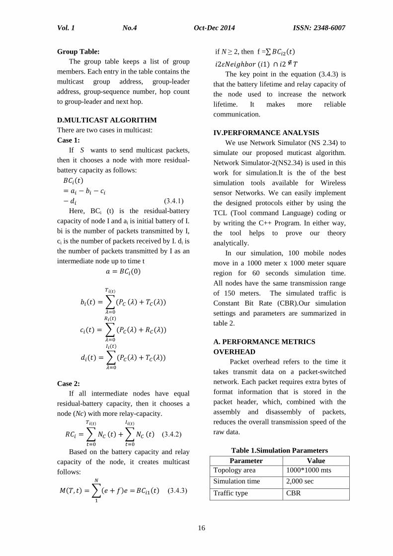
IV.PERFORMANCE ANALYSIS We use Network Simulator (NS 2.34) to simulate our proposed muticast algorithm. Network Simulator-2(NS2.34) is used in this work for simulation.It is the of the best simulation tools available for Wireless sensor Networks. We can easily implement the designed protocols either by using the TCL (Tool command Language) coding or by writing the C++ Program. In either way, the tool helps to prove our theory analytically. In our simulation, 100 mobile nodes move in a 1000 meter x 1000 meter square region for 60 seconds simulation time. All nodes have the same transmission range of 150 meters. The simulated traffic is Constant Bit Rate (CBR).Our simulation settings and parameters are summarized in table 2.
A. PERFORMANCE METRICSOVERHEAD Packet overhead refers to the time it takes transmit data on a packetnetwork. Each packet requires extra bytes of format information that is stored in the packet header, which, combined with the assembly and disassembly of packets, reduces the overall transmraw data.
Table 1.Simulation ParametersParameter
Topology area
Simulation time
Traffic type
ISSN: 2348-6007
2 point in the equation (3.4.3) is
that the battery lifetime and relay capacity of the node used to increase the network lifetime. It makes more reliable
PERFORMANCE ANALYSIS We use Network Simulator (NS 2.34) to
simulate our proposed muticast algorithm. 2(NS2.34) is used in this
work for simulation.It is the of the best simulation tools available for Wireless sensor Networks. We can easily implement
gned protocols either by using the TCL (Tool command Language) coding or by writing the C++ Program. In either way, the tool helps to prove our theory
In our simulation, 100 mobile nodes move in a 1000 meter x 1000 meter square
0 seconds simulation time. All nodes have the same transmission range of 150 meters. The simulated traffic is Constant Bit Rate (CBR).Our simulation settings and parameters are summarized in
PERFORMANCE METRICS
ead refers to the time it takes transmit data on a packet-switched network. Each packet requires extra bytes of format information that is stored in the packet header, which, combined with the assembly and disassembly of packets, reduces the overall transmission speed of the
Table 1.Simulation Parameters Value
1000*1000 mts
2,000 sec
CBR
Vol. 1 No.4 Oct-Dec 2014 ISSN: 2348-6007
17
CBR packet size 512 bytes
Node mobility 0 to 20 mts/sec Frequency 2.4 GHz
Channel capacity 2 Mbps
Transmission range 150mts
Transmission power 1,4000 mts
Receiving power 1,000 mW
Idle power 830mW
Mobility Model Random waypoint
Voltage 5v
Group size 3,6,9,12,15
Pause time 1 sec
Protocol AODV PACKET DELIVERY RATIO It is the ratio of the number of packets received successfully and the total number of packets transmitted. THROUGHPUT The throughput is averaged that the number of packet received without loss at the output. It is the measurement of how fast the packets that carrying the information can pass through a point.
ENERGY CONSUMPTION Energy consumption refers to the total energy consumed by the setup during the entire data transmission-reception process. V. RESULTS AND DISCUSSION In order to evaluate the network performance, it uses the metrics such as network life time, energy consumption, throughput, power consumption, over head. Secondly, it presents the experimental results of all the five models. Thirdly, it compares the performances of all the four models. A.ENERGY CONSUMPTION Shows the evaluation of Erms for different time instances. Intially all the nodes are consume zero energy. From the results, it concludes that the MIP model has reached at
the top position as compared to both the proposed model and LAM model in terms of Erms. As time increases the energy consumption of all nodes will increase due to mobility. So system requires more number of route paths to perform well. Hence it takes high energy consumption over the network. B.THROUGHPUT Here, it consists of 100 mobile nodes within the defined area and the node mobility speed varies from 0–30 mts/sec. The setup executed for 25 runs with the different speed in a given topology and 50 mobile nodes transmit the data at the rate of 5 packets/sec. The mobility is inversely proportional to throughput. The proposed model works well if the node mobility between 0–12 mts/sec. When the mobility isincreased (25 mts/sec), the MP-MAODV, MIP, LAM,MAODV and proposed models have transmitted 68%, 50%, 59%, 60%, 62% of the packets respectively as shown in FIG. The results have confirmed that the network through put decreases, when the node mobility increases. However, increasing in number of the nodes, the network throughput does not change substantially. The proposed model is more sensitive to the number of nodes. At low mobility and less number of the nodes, the throughput is higher than the MP-MAODV and MIP models, but in a larger network this value has dropped faster as compared to the MP-MAODV model.
C.POWER CONSUMPTION Shows the evaluation of Erms for different time instances. Intially all the nodes are consume zero energy. From the results, it concludes that the MIP model has reached at the top position as compared to both the proposed model and LAM model in terms of Erms. As time increases the energy consumption of all nodes will increase due to mobility. So system requires more number of
Vol. 1 No.4
route paths to perform well. Hence it takes high energy consumption over the network.
D.OVERHEAD Packet overhead refers to the time it takes transmit data on a packetnetwork. Each packet requires extra bytes of format information that is stored in the packet header, which, combined with the
E.COMPARISON RESULTS
Table 4.2 Comparison between proposed model and existing modelsParameter MIP
Life time 7,450 s
Energy Consumption High
Through put 250
End-to-end Delay 0.045s
The table 4.2 shows the comparison results between proposed model and various algorithms. The parameters discussed above proved to provide better performance in proposed model.
F.SIMULATION RESULTS
Figure 4.1 overhead
Figure 4.2 Power Consumption
Oct-Dec 2014
18
route paths to perform well. Hence it takes mption over the network.
Packet overhead refers to the time it takes transmit data on a packet-switched network. Each packet requires extra bytes of format information that is stored in the packet header, which, combined with the
assembly and disassembly of packets, reduces the overall transmission speed of the raw data. The overhead decreases from 90 to 30 when the group size increases from 2 to 18. The proposed model gives better results compared with LAM, MIP MPand MAODV.
COMPARISON RESULTS Table 4.2 Comparison between proposed model and existing models
MIP LAM MAODV MP-MAODV 7,450 s 6,445s 7,250s 7,450s
High Low low Low
pkts 295 pkts 300 pkts 340 pkts
0.045s 0.044s 0.044s 0.047s
The table 4.2 shows the comparison results between proposed model and various algorithms. The parameters discussed above
provide better performance in
SIMULATION RESULTS
Figure 4.1 overhead
Figure 4.2 Power Consumption
Figure 4.3 Energy Consumption
Figure 4.4 Throughput
ISSN: 2348-6007
isassembly of packets, reduces the overall transmission speed of the
The overhead decreases from 90 to 30 when the group size increases from 2 to 18. The proposed model gives better results compared with LAM, MIP MP-MAODV,
Table 4.2 Comparison between proposed model and existing models Proposed Model
8,150s
Very low
310 pkts
0.042s
Figure 4.3 Energy Consumption
Figure 4.4 Throughput
Vol. 1 No.4 Oct-Dec 2014 ISSN: 2348-6007
19
VI .CONCLUSION In this paper the main design contains in the MANET is that the mobile nodes are energy constrained. Here the multicast algorithms are developed to reduce the energy consumption of all the nodes in the network. The proposed algorithms is different from the existing algorithms. The proposed algorithms exhibit more lifetime of the node and network, and throughput when compared with other algorithms. . It is addressed with few limitations against the power-aware metrics in the multicast algorithms. The stimulation results in this paper shows that proposed model improved the network lifetime by 20% on average. Extending network lifetime is accomplished by finding multicast protocols that tends to minimize the variation of remaining energy of all nodes. The power-aware multicast protocols tend to create additional control traffics. The basic mechanism in this work is highly extensible and supports QoS for the MANETs.
A.FUTURE WORK Future work is to be implemented with the cross layer by interfacing the network layer and transport layer for easy communication. Integration of power aware will be implemented. Congestion avoidance scheme will be implemented to improve packet delivery ratio. VII. REFERENCES 1. Cagalj, M Enz, C. Hubaux, J. P.(2002)
‘Minimum-energy broadcast in wireless Networks: NP-completeness and distribution issues’, in Proceedings ACM
8th Annual International Conference on Mobile Computing Networks pp.No.172–182.
2. Cheng, W. H. Feng, K.-T. and Wen, C.-Y. (2006) ‘Power controlled hybrid Multicast routing protocol for mobile ad hoc networks,’ in Proceedings of IEEE
Vehicular Technology Conference pp.No.1087–1089. 3. Ephremides, A. Nguyen, G. D. and
Wieselthier, J. E. (2001) ‘Algorithms for energy-efficient multicasting in static ad hoc wireless networks,’ Journal of Mobile Networks Vol.6, No.3, pp.No.251–263.
4. Floréen, B. Kaski, P. Kohonew, J. and Orponen, P. (2003) ‘Multicast time maximization in energy constrained wireless networks,’ in Proceedings Workshop Foundation on Mobile Computing pp.No.50–58.
5. Galvez, J. J. Gómez-Skarmeta, A. F. and Ruiz, P. M. (2008) ‘Spatially disjoint multipath routing protocol without location information,’ in Proceedings of IEEE Conference on Local Computer Networks, pp.No.570–571.
6. Guo, X. and Liang, W (2006) ‘Online multicasting for network capacity maximization in energy-constrained ad hoc networks,’ IEEE Transactions on
Mobile Computing Vol.5, No.9, pp.No.1215–1227.
7. Gupta, S. K. S. and Wang, B. (2003) ‘S-REMiT, an algorithm for enhancing energy efficiency of multicast trees in wireless ad hoc networks,’ in Proceedings of IEEE GLOBECOM pp.No.3519–3524.
8. Kamboj, P. and Sharma, A. K. (2008) ‘Power aware multicast reactive routing protocol,’ International Journal on Computer Science and Network Security, Vol.8, No.8, pp.No. 351–357.
9. Kang, I. and Poovendran, R. (2003) ‘Maximizing static network lifetime of Wireless broadcast ad hoc networks,’ in Proceedings of IEEE International Conference on Communication pp.No.2256–2261.
10. Liang, W. (2006) ‘Approximate minimum-energy multicasting in wireless adhoc networks,’ IEEE
Vol. 1 No.4 Oct-Dec 2014 ISSN: 2348-6007
20
Transactions on Mobile Computing Vol.5, No.4, pp.No.377–387.
11. Nguyen, G. D.Ephremides, A. and Wieselthier, J. E. (2000) ‘On the construction of energy-efficient broadcast and multicast trees in wireless Networks,’ in Proceedings of IEEE 9th Annual Joint Conference IEEE Computer Communication Society pp.No.585–594.
12. Perkins, C. E. and Royer, E. M. (1999) ‘Multicast operation of the ad-hoc on demand distance vector routing protocol,’ in Proceedings of 5th Annual
ACM/IEEE International Conference on Mobile Computing and Networks pp.No.207–218.
13. Raghavendra, C. S. Singh, S. and Woo, M. (1998) ‘Power-aware with routing in mobile adhoc networks,’ in Proceedings of ACM MOBICOM pp.No.368–369.
14. Ruiz, P. M. and Sanchez, J. A. (2006) ‘Improving delivery ratio and power efficiency in unicast geographic routing with a realistic physical layer for wireless sensor networks,’ in Proceedings 9th EUROMICRO Conference Digital System Design Architecture Methods Tools, pp.No.591–597.
15. Tan, L. and Zhao, S. (2007) ‘A distributed energy efficient multicast routing algorithm for MANETs,’ International Journal on Sensor Networks Vol.2, No.1–2, pp.No. 62–67.
16. Wang, B. and Gupta, S. K. S. (2003) ‘Energy efficient multicast trees in wireless ad hoc networks,’ in Proceedings IEEE International Symposium on Network Computing Application pp.No.265–272.
17. Yang, W. L. (2005) ‘Constructing energy-efficient multicast trees with delay constraints in ad hoc networks,’ in Proceedings of International Conference on Advanced Information Networking
and Applications pp.No.414–419. 18. Yuan, P. and Zhang, J. (2012) ‘An
energy constrained multicast routing protocol,’ in Proceedings of International Conference on Wireless Communication Networks and Mobile Computing pp.No.65–72.
Vol. 1 No.4 Oct-Dec 2014 ISSN: 2348-6007
21
IRIS BIOMETRICS FOR EMBEDDED SYSTEMS
G.Sathya PG Scholar M.E-EST, Vivekanandha institute of Engineering and Technology for Women
S.Arun
Assisant professor/ECE, Vivekanandha institute of Engineering and Technology for Women
M.Dharani
PG Scholar M.E-EST, Vivekanandha Institute of Engineering and Technology for Women
Abstract In many applications user authentication has to be carried out by portable devices.
Usually these devices are personal tokens carried by users, which have many constraints
regarding their computational performance, occupied area, and power consumption. These kinds of devices must deal with such constraints, while also maintaining high performance rates in the
authentication process . This paper provides solutions to designing such personal tokens where biometric authentication is required. In this paper , iris biometrics have been chosen to be
implemented due tothe low error rates and the robustness their algorithms provide. Several design alternatives are presented, and their analyses are reported . With these results, most of the needs
required for the development of an innovative identification product are covered. Results indicate that the architectures proposed herein are faster (upto 20 times), and are capable of obtaining
error rates equivalent to those based on computer solutions. Simultaneously, the security and cost for large quantities are also improved.
I. INTRODUCTION BIOMETRICS is the only method capable of recognizing human beings using the real features of the user instead of his or her knowledge (e.g., passwords) or belongings (e.g., a magnetic stripe card). Among currently existing biometric modalities , iris recognition is considered to be one of the most secure and reliable technologies however ,while matching algorithms in iris recognition are straightforward, the signal processing prior to matching requires a significant amount of processing power. Biometric applications can be classified into two Biometric applications can be classified into two major group: identification and authentication.
Identification is performed when the user identity is not provided, wherein the system must find the user from a database of biometric data from all enrolled users. In contrast, authentication, is the process of checking the identity of the user using provided biometric data.
Block diagram of Biometric System
Vol. 1 No.4 Oct-Dec 2014 ISSN: 2348-6007
22
Biometric authentication applications can be designed by following two key approaches online, which requires communication with central databases to access biometric data and offline, wherein biometric data is stored on personal tokens.
II. STATE OF THE ART IN IRIS
BIOMETRICS From a conceptual point of view, most iris recognition systems have the same block diagram as any other biometric modality. After capturing an image of the eye, the iris is located and segmented to extract its features; these features are then compared to a previously stored template. A. Iris Acquisition Contrary to popular belief, iris biometrics systems do not use laser-scans to capture the image of the human eye. Instead, an infrared photo or video camera is used at a set distance to capture a high quality image of the iris. Working in the infrared range provides many advantages when compared to the visible range :iris ridges, nerves, and crypts are more evident [31]; the border between the iris and the pupil is more pronounced; and users are not exposed to annoying flashes. B. Iris Segmentation The main purpose of this process is to locate the iris on the image and isolate it from the rest of the eye image for further processing. Some other important tasks that are also performed in this iris segmentation block include image quality enhancement, noise reduction, and emphasis of the ridges of the iris. C. Feature Extraction We begin with normalization of the segmented iris image. This normalization becomes necessary when considering that the pupil varies in size for different light
intensities. The normalization method varies from changes to the polar coordinate system.
III. IMPLEMENTATION • Image Acquisition The iris is captured with an infrared camera, as previously mentioned. The cost and size of the electronics and lens required for this task are not commercially viable for insertion into the personal token.
• Image Segmentation This preprocessing block is related to the image acquisition. The non-detection of the iris or the quality of the captured images are typical reasons for rejection of the acquired image, thus, requiring a new capture process. If this block were included in the token, many images would have to be transferred from the terminal to the token, increasing data communication and therefore the verification time The personal token should have the following characteristics. • It should perform the rest of the biometric
processes, i.e., feature extraction, comparison, and the matching result processing.
• It is highly recommended to be reconfigurable. Possible token robberies or user accidents would require changes in biometric data or internal token processes to avoid security holes.
Vol. 1 No.4 Oct-Dec 2014 ISSN: 2348-6007
23
Terminal and platform functionalities • The token should be able to build and
handle a secure communication channel with the terminal.
• The token should be designed as a tamper-proof device.
• As it has to be portable, the occupied electronic area should be as small as possible.
• Although token size is limited, the processing time must be minimal to reduce user waiting time.
• Finally, the device must be cost effective, as large quantities of these devices will be manufactured. In order to study different implementation proposals, this section is organized as follows. First, we will centre on the chosen algorithm from a signal processing viewpoint. This is followed by the different implementations developed.
Abstraction layers in a computer system and its relationship for biometric system implementation platforms.
Architecture of the microprocessor
platform
B. Platforms Considered When designing identification tokens, several approaches may be studied. Current authentication algorithms have primarily been implemented in personal computers; however, these devices are not suitable for tokens due to their reduced size and cost. Nevertheless, the authors consider this platform as the initial stage for this study. Computers are not the only devices that can be used to implement biometric systems. It represents several different approaches that have been considered. 1) Microprocessor A computer is based on one or several microprocessors. Above these, several logical layers provide the user a transparent control of the electronics , which are based on an Operating System. Although this architecture eases the development of applications, these programs are not optimally translated to microprocessor instructions. Therefore, our first proposed implementation consists of a platform based on a microprocessor, which makes reasonable and optimal use of the peripherals and instructions for the functions that are to be developed .In order to develop a biometric personal token, this platform is composed of the following peripherals. • Serial Interface: Serial interface will be
used so that the token can communicate with the terminal for data transfer rand commands. The choice of physical interface is not crucial ,i.e., from RS-232 to a USB 2.0 port.
• RAM Memory: As in any microprocessor system temporary memory storage is required. This memory will be used for storing data such as the segmented iris image, computational variables , etc.
• ROM Memory: For storing executable code and programming constants.
• EEPROM Memory: This stores the user template, allowing any changes if
Vol. 1 No.4 Oct-Dec 2014 ISSN: 2348-6007
24
necessary. Other verification parameters , the different threshold levels can also be stored here.
The point of service terminal acquires the user’s eye image and performs the described segmentation. The resulting image, together with other information, such as the inner and outer boundary parameters, is transmitted through the serial interface. As the token platform receives these data, it stores these data in the RAM. Once the transmission is finished, the token will begin its role by calling the normalization block. Afterwards, the feature extraction block based on the zero-crossing representation of the wavelet transform is executed. The resulting vector is then compared with the internally stored template and makes a decision on the matching result. Such decisions are transmitted back to the terminal by the serial interface. Once all of the processes are finished, the RAM is completely erased for later use. Benefits from this approach when considering the computer platform are, as already mentioned, the optimization of all resources, no extra memory and overhead computations due to the presence of operating systems. A standalone execution is carried out, and only required functions are implemented, which is not the case with general purpose computers. The main drawbacks of this approach are related to the development and maintenance of the application. Another important issue to consider is that most microprocessors are intended for use in embedded systems , and do not use floating-point arithmetic, wherein the truncation needed for implementing these algorithms in a fixed point arithmetic unit can cause error accumulation.
IV. CONCLUSION AND FUTURE
WORK Different platforms were studied for biometric authentication scenarios. Two platforms have been designed and developed: a microprocessor-based architecture and a dedicated hardware sign. Each platform exhibits benefits when compared to general purpose computer systems. Selecting one of these platforms depends on system and authentication application requirements. In the case of high security environments, where low error rates are extremely important, the microprocessor solution is recommended, especially when the number of users in the system is relatively high; however, if the number of users is lower size and execution times are significant constraints, the dedicated hardware solution should be chosen. The obtained processing times exhibit the best results for the dedicated hardware solution, improving by over200 times over microprocessor-based
Vol. 1 No.4 Oct-Dec 2014 ISSN: 2348-6007
25
solutions, and the request of a clock rate two times faster .The results obtained in this study direct future research into the integration of cryptographic modules that would secure all data transmission. V.REFERENCES 1. [1] A. Jain, R. Bolle, and S. Pankanti, , S.
P. A. Jain and R. Bolle, Eds., Biometrics: Personal Identification in a Networked
Society. Norwell, MA: Kluwer, 1999. 2. M. Faundez-Zanuy, “Biometric security
3. J. Mansfield and J. L. Wayman, Best practices in testing and reporting
performance of biometric devices U.K. Government Biometrics Working Group, 2002. [Online]. Available: http://www.npl.co.uk/upload/
pdf/biometrics_bestprac_v2_1.pdf
4. P. Phillips, W. T. Scruggs, A. J. O’Toole, P. J. Flynn, K. W. Bowyer, C. L. Schott, and M. Sharpe, “FRVT 2006 and ICE 2006 large-scale results,” Nat. Inst. Standards Technol., 2007. [Online]. Available: http://www.frvt.org/FRVT2006/docs/ FRVT2006andICE2006LargeScaleReport.pdf
Velalar College of Engineering and Technology, Erode – 638012.
ABSTRCTThis project deals with the design and realization of low cost ecofriendly energy efficient
refrigerator cum oven system. The proposed system is designed for lower power consumptionwith reduced size. Current refrigeration systems in usage produce toxic gases like CFC, Freon
etc.To overcome the above draw backs, a new system has been proposed which consumes only60watt of power and uses water as a cooling medium instead of toxic gases. In addition, the
radiated heat energy has been used for oven application.
INTRODUCTIONToday's energy consumption in the
whole world is high and availability ofenergy is not available all places due to highconsumption of energy and now weintroduce our system. Nowadays people userefrigerators produce more toxic gases. Butour system does not produce any toxic gases
PROPOSED METHODOLOGYTwo modules are required for this
system to realize the proposed method. Politer module assembly Temperature sensor
PELITIER MODULEThe semiconductor materials are N and P
type, and are so named because either theyhave more electrons than necessary tocomplete a perfect molecular lattice structure(N-type) or not enough electrons to completea lattice structure (P-type). The extraelectrons in the N-type material and the holesleft in the P-type material are called“carriers” and they are the agents that movethe heat energy from the cold to the hotjunction.
Heat absorbed at the cold junction ispumped to the hot junction at a rateproportional to carrier current passingthrough the circuit and the number ofcouples. Good thermoelectric semiconductormaterials such as bismuth telluride greatlyimpede conventional heat conduction fromhot to cold areas, yet provide an easy flowfor the carriers. In addition, these materialshave carriers with a capacity for transferringmore heat. Thermoelectric cooling couples(Figure 1) are made from two elements ofsemiconductor, primarily Bismuth Telluride,heavily doped to create either an excess(n-type) or deficiency (p-type) of electrons.Heat absorbed at the cold junction is pumpedto the hot junction at a rate proportional tocurrent passing through the circuit and thenumber of couples.
Figure 1: Thermoelectric moduleAssembly
Vol. 1 No.4 Oct-Dec 2014 ISSN: 2348-6007
33
TEMPERATURE SENSOR: The Adriano LM35 Linear temperature sensor module is based on the semiconductor LM35 temperature sensor. The LM35 linear temperature sensor module can be used to detect ambient air temperature. This sensor is produced by National Semiconductor Corporation and offers a functional range between -40 degree Celsius to 150degree Celsius. Sensitivity is 10mv per degree Celsius. The output voltage is proportional to the temperature. It is commonly used as a temperature measurement sensor. It includes thermocouples, platinum resistance, thermal resistance and temperature semiconductor chip, which commonly used in high temperature measurement thermocouples.
Platinum resistance temperature used in the measurement of 800 degrees Celsius, while the thermal resistance and semiconductor temperature sensor suitable for measuring the temperature of 100-200 degrees or below, in which the application of a simple semiconductor temperature sensor has good linearity and high sensitivity. The LM35 linear temperature sensor and sensor-specific expansion of Adriano board, in combination, can be very easy to achieve.
METHODOLOGY: THERMOELECTRIC REFRIGERATION WHAT IS IT? HOW DOES IT WORK? WHAT IS THERMOELECTRIC REFRIGERATION? Refrigeration is the process of pumping heat energy out of an insulated chamber in order to reduce the temperature of the chamber below that of the surrounding air. Thermoelectric refrigeration uses a principle called the "PELTIER" effect to pump heat electronically. The Peltier effect is named after a French scientist who discovered it in 1834. HOW DOES IT WORK? In 1834 Jean Peltier noted that when an electrical current is applied across the junction of two dissimilar metals, heat is removed from one of the metals and transferred to the other. This is the basis of thermoelectric refrigeration. Thermoelectric modules are constructed from a series of tiny metal cubes of dissimilar exotic metals which are physically bonded together and connected electrically. When electrical current passes through the cube junctions, heat is transferred from one metal to the other. Solid-state thermoelectric modules are capable of transferring large quantities of heat when connected to a heat absorbing device on one side and a heat dissipating device on the other. The Koolatron's internal aluminum cold plate fins absorb heat from the contents, (food and beverages), and the thermoelectric modules transfer it to heat dissipating fins under the control panel. Here, a small fan helps to disperse the heat into the air. The system is totally environmentally friendly and contains no hazardous gases, nor pipes nor coils and no compressor. The only moving part is the small 12-volt fan. Thermoelectric modules are too expensive for normal domestic and commercial applications which run only on
Vol. 1 No.4 Oct-Dec 2014 ISSN: 2348-6007
34
regular household current. They are ideally suited to recreational applications because they are lightweight, compact, insensitive to motion or tilting, have no moving parts, and can operate directly from 12-volt batteries. WORKING
The supply is given to the TECI-12706 module. Due to this, cooling is produced. Due to this the water present in the aluminum tank has been cooled . By using Air pump(X-12), water will be pumped to the aluminum tube around the refrigerator and it is cooled. Again the water is pumped back to the aluminum tank as a cyclic process.
The supply is given to the TECI-12706 module. Due to this, heating is produced. Due to this the water present in the copper
tank has been heated. By using 2600DH pump, water will be pumped to the copper tube around the oven and it is heated. Again the water is pumped back to the copper tank as a cyclic process. TEMPERATURECONTROL METHOD
Estimate of Acceptable Temperature Rise
Above Ambient
MODULE SET UP FOR COOLING AND HEATING
APPLICATION OF REFRIGERATOR Thermoelectric cooling is used in
medical and pharmaceutical equipment, spectroscopy systems, various types of detectors, electronic equipment, portable refrigerators, chilled food and beverage dispensers, and drinking water coolers.
Drinking water coolers.
Natural Convection
20OC to 40 OC
Forced Convection
10OC to 15OC
Liquid Cooling
2OC to 5 OC (rise above the liquid coolant temperature)
Vol. 1 No.4 Oct-Dec 2014 ISSN: 2348-6007
35
Requiring cooling devices with high reliability that fit into small spaces, powerful integrated circuits in today's personal computers also employ thermoelectric coolers.
Some of the other potential and current uses of thermoelectric cooling are
APPLICATION OF OVEN Oven protection system as set forth in
further including a controller and a sensor operatively mounted to the thermo-forming machine and adapted to sense a predetermined condition and to send a signal to said controller, said controller operable to actuate said prime mover to move said barrier from said stored position to said deployed position.
Due to the relatively low temperatures at which they operate (at least compared to kilns, incinerators and other industrial ovens), most ovens in use in the laboratory do not feature refractory insulation. However, this insulation is included in some higher temperature models of laboratory
Oven in order to provide the user with a safer operating environment
Other than the smaller bench top and cabinet ovens which are perhaps the most commonly seen varieties of laboratory oven
CONCLUSIONS AND SCOPE FOR FUTURE DEVELOPMENT MOTIVATION The urge for betterment comes from motivation. Some of the motivating factors for thermoelectric are as follows:
Create new classes of thermoelectric devices by:
- synthesizing, measuring and assembling novel thermoelectric materials
- Constructing and measuring novel structures such as super lattices, quantum wells etc.
Offer at least an order of magnitude enhancement in current performance making these devices competitive with conventional phase change systems(ZT>4)
Techniques for the production of low-dimensional conductors.
Better ways of using the present thermoelectric modules.
CFC ban should increase market for all sorts of alternate refrigeration technologies.
POTENTIAL RESEARCH SCOPE IN MATERIALS FIELD
tolerance to repeated temperature cycling.
broad range of temperature over which ZT is high.
low cost. weight, volume and vibration
concerns. CONCLUSIONS Thermoelectrics and thermoelectric cooling are being studied exhaustively for the past several years. Thermoelectric refrigerators are greatly needed, particularly for developing countries, where long life, low maintenance and clean environment are needed. In this aspect thermoelectrics cannot be challenged in spite of the fact that it has some disadvantages like low coefficient of performance and high cost.
Vol. 1 No.4 Oct-Dec 2014 ISSN: 2348-6007
36
REFERENCE FOR EFRIGERATOR 1. R.B. Horst, L.R. Williams, in Proceedings
of the 3rd International Conference on Thermoelectric Energy Conversion, Arlington, Texas (IEEE, New York, 1980), p. 183.
2. T.P. Hogan, T. Smith, in Thermoelectric Handbook: Macro to Nano, ed. by D.M. Rowe (CRC Taylor and Francis, Boca Raton, 2006), p. 12–5.
2. McGee, Harold. On Food and Cooking: The Science and Lore of the Kitchen, revised 2004
3. Ojakangas, Beatrice. Cooking with Convection, Everything You Need to Know to Get the Most from Your Convection Oven, 2009.
4. Milwaukee State Journal. April 20, 1967. p. 10. |chapter= ignored
5. http://www.smeg.com/faq/ovens/what-s-the-difference-between-fan-and-fan-assisted-ovens/ What's the difference between fan and convection ovens? Retrieved on 20 July 2013.
6. http://service.hoover.co.uk/advice-centre/built-in-appliances/ovens/troubleshooting/ Ovens Advice Centre Retrieved on 20 July 2013
SMART POWER GENARATION AND CONSERVATION FROMOVERHEAD, TANKS
R.Jawahar, M.Dhivya, Ebinzachariavarghese, K.MenakaMr.S.Ashwanth. ME
Velalar College of Engineering and Technology, Erode – 638012
AbstractIn this project, the water storage tank is utterly monitored and the entire operation related
to the tank such as water fillings and consuming’s are exclusively automated .Al so the power isgenerated from the inlet line of the water tank with the help of micro turbine. Main objective ofthis project is to store the water from overflow and generating the power from same. This project
deals with utilization of unused kinetic energy from the inlet of the water tank, which is used toproduce power. The generated power from the micro turbine is stored in the battery, which can be
used for electrical and electronics appliances. In the existing system, water filling in overhead tankis done in manual ways by switching ON and OFF of motors and also it was not monitored
properly. That leads to both wastage of water and electricity. In this proposed project, the waterlevel will be monitored by using simple logic gates and generate the power with the help of micro
turbines from the overhead tanks. The pumping action is entirely controlled by microprocessorand it is fully automated.
INTRODUCTIONIn this project the water storage tank is
utterly monitored and the entire operationrelated to the tank such as water fillings andconsuming are exclusively automated.Also, the power is generated from the outleta line of the water tank. The powergeneration is done with the help of microturbine.
OBJECTIVESMain objective of this project is to store
the water from overflow and generating thepower from same. This project deals withutilization of unused kinetic energy from theoutlet of water tank, which is used to producepower. The generated power from the microturbine is stored in the battery, which can beused for electrical and electronics appliances.
EXISTING SYSTEMIn the existing system, water filling in
overhead tank is done in manual ways by
switching ON and OFF of motors on timeand also it was not monitored properly.That leads to both wastage of water andelectricity. Also, there were some projectswhich control the motor by sensing waterlevels, it was not fully automated whichmeans it can sense only the water level.Also there was no utilization of height ofoverhead tank.
DRAWBACKS OF THE EXISTINGSYSTEM Wastage of the water from outlets
Waste of electricity
In the apartments, it is hard to monitorthe water tank
No Power production from outlets oftank
PROPOSED SYSTEMIn this proposed model, we generate the
power with the help of micro turbines from
Vol. 1 No.4 Oct-Dec 2014 ISSN: 2348-6007
38
the overhead tanks. The pumping action is entirely controlled by microprocessor and it is fully automated. This project utilizes and controls both the corporation water and underground water at the same time. The generated power from the micro turbine which can be installed in the outlets of the tank will stores in battery. By this way we preserve the energy. The two parts this system is,
• Power generation
• Pumping action controller
PUMPING ACTION CONTROLLER This unit consists of the following parts,
• Pump
• Tube switch
• Micro controller unit
• Transmitter and receiver circuit
• Water sensor WORKING OF PUMPING ACTION CONTROL The block diagram of working of pumping action control is shown in Fig 1.1. In this circuit, the supply of 5V is given to the Tube switch and microcontroller. The Float sensor and Tube switch is used to measure the water level of the overhead tank. If the water is empty, then the transmitter will sends a signal to the receiver. Then the receiver used to pass that received signal to the microcontroller. The microcontroller, which is programmed like to send a message to the motor drive to switched ON the motor. Then the sump on the motor will be used to suck the water and pumps it to the overhead tank with the help of pipe lines. When the water reaches the certain level, the Tube switch is made to close automatically by receiving the signal from transmitter. Then the receiver feds the received signals to the microcontroller. Then the microcontroller sends a message signal to the motor drive to stop the motor.
Tube switch A Tube switch is a device used to detect the level of liquid with in a tank. The switch may be used in a pump, an indicator, an alarm, or other devices. Tube switches range from small to large and may be as simple as a mercury switch inside a hinged float or as complex as a series of optical or conductance sensors producing discrete outputs as the liquid reaches many different levels within the tank. Perhaps the most common type of Tube switch is simply a float raising a rod that actuates a micro switch. A very common application is in sump pumps and condensate pumps where the switch detects the rising level of liquid in the sump or tank and energizes an electrical pump which then pumps liquid out until the
Vol. 1 No.4 Oct-Dec 2014 ISSN: 2348-6007
39
level of the liquid has been substantially reduced, at which point the pump is switched off again. Tube switches are often adjustable and can include substantial hysteresis. This minimizes the on-off cycling of the associated pump. Some Tube switches contain a two-stage switch. As liquid rises to the trigger point of the first stage, the associated pump is activated. If the liquid continues to rise (perhaps because the pump has failed or its discharge is blocked), the second stage will be triggered. This stage may switch off the source of the liquid being pumped; trigger an alarm, or both. WORKING OF POWER GENERATION
Fig . Power generation section from overhead tank
Fig shows the Power generation section from overhead tank. The tank was fixed at some of the maximum height from the ground level. The outlet from the tank is at the bottom of the tank. Due to gravitational force, the pressure of the water from outlet will be at the maximum. The Micro turbine is going to fix at the bottom of the outlet. So that turbine
blade will rotate due to the kinetic energy of the water. Then this energy is converted into electrical energy by means of the generator. Then the generated AC power is converted into DC by means of the converter circuits and stores in the battery. Finally inverted output is directly consumed by the household appliances.
Rectifier A rectifier is an electrical device that converts alternating current (AC), which periodically reverses direction, to direct current (DC), which flows in only one direction. The process is known as rectification. Because of the alternating nature of the input AC sine wave, the process of rectification alone produces a DC current that, though unidirectional, consists of pulses of current. Many applications of rectifiers, such as power supplies for radio, television and computer equipment, require a steady constant DC current (as would be produced by a battery).
Buck Boost Converter The basic principle of the buck–boost converter is shown in Fig.1.5. • While in the On-state, the input voltage
source is directly connected to the inductor (L). This results in accumulating energy in L. In this stage, the capacitor supplies energy to the output load.
• While in the Off-state, the inductor is connected to the output load and capacitor, so energy is transferred from L to C and R.
Fig : Operation of buck boost converter
Vol. 1 No.4 Oct-Dec 2014 ISSN: 2348-6007
40
Inverter
A power inverter, or inverter, is an electronic device or circuitry that changes direct current (DC) to alternating current (AC). In one simple inverter circuit, DC power is connected to a transformer through the center tap of the primary winding. A switch is rapidly switched back and forth to allow current to flow back to the DC source following two alternate paths through one end of the primary winding and then the other. The alternation of the direction of current in the primary winding of the transformer produces alternating current (AC) in the secondary circuit.
ADVANTAGES OF PROPOSED SYSTEM
• Fully automated control
• Wastage of water is reduced
• Utilization of outlet water to generate power
• Economics of power generation
• Implemented in all places
DESIGN SPECIFICATION OF THIS PROJECT Input voltage: For controllers - 5volts For motors – 230V Input current : For controllers – 0.5A (Max) For motors – 5A Power Generation: 30 watts /hour (Max)
REFERENCES: 1. P. Thounthong, B. Davat, S. Rael, and
P. Sethakul, “Fuel cell high-power applications—An overview of power converters for a clean energy conversion technology,” IEEE Ind.
Electron. Mag., vol. 3, no. 1, pp. 32–46, Mar. 2009.
2. L. Zhu, “A novel soft-commutating isolated boost full-bridge ZVS-PWM DC–DC converter for bidirectional high power applications,” IEEE Trans.
Power Electron., vol. 21, no. 2, pp. 422–429, Mar. 2006.
3. T.-F. Wu, Y.-S. Lai, J.-C. Hung, and Y.-M. Chen, “Boost converter with coupled inductors and buck–boost type of active clamp,” IEEE Trans. Ind.
Electron., vol. 55, no. 1, pp. 154–162, Jan. 2008.
4. International Rectifier IRFB3077 Datasheet PD-97047A, 020806.
NON-CONVENTIONAL POWER GENERATION FROMHUMAN DROPPINGS
T.Anitha, J.Anjapulikannan, D.Karthikeyan, S.GirinathFinal Year B.E, Electrical and Electronics Engineering
MR.K.Rajaram, AP(Sr.Gr.)/ EEE DEPARTMENTVelalar College of Engineering and Technology, Erode-638012.
ABSTRACTSince urine is produced every where, and a lot of it too humans alone are estimated to
produce 6.4 trillion liters a year this idea has a strong local flavor. The ability to produce energy
locally could give this technology an edge against other renewable energies such as solar andwind that are only cost-effective in certain areas.
The solar concentrators used to provide industrial process heating or cooling, such as in solarair-conditioning.
Urine’s major constituent is urea, which incorporates four hydrogen atoms permolecule – importantly, less tightly bonded than the hydrogen atoms in water molecules.
From one liter of urine we can get enough amount of six hours of electricity.In this topic we generate electricity from urine this nothing but from urine. This is also
called as pee powered generator. Here in this topic the main fuel is urine. Generally the urine hasmajorly water in addition to other chemicals like ammonia, sulphate, uric acid, urea etc. here the
urine is passed to the electrolytic cell and from which hydrogen gas is evolved after electrolysiswhich is main component for generation. Here in urine urea is also a major component after water
generally urea is chemical formula is CH4N2O here the four hydrogen molecules is weakly bondedwith the other components.
Thus this hydrogen gas is passed through various components this purified gas is given tothe generator which generates the electricity.
INTRODUCTION:The specific project objectives are to:
Design and develop a mirror moduleusing an inexpensive reflective film
bonded onto a lightweight structuralrigid foam support
Design and develop a low-cost, non-traditional mirror-module support
structure Select low-cost drive components
and associated control system Design, integrate, and test a low-
cost concentrator
Analyze the system's cost todemonstrate achieving the $75/m2
collector system target.In all over world the fossil fuels like coal
are being exhausted day by day. And due tothis we are going for alternate sources likesolar power, wind power, nuclear power, andhydroelectric power. All this generationsrequire high capital cost. So because of thatthere are some many research is going on forlow cost energy generation.
Some scientist found a fuel which iscalled as the fuel of future that is nothing buturine. With the help of urine we can generateelectricity in very simple manner as we allconsider pee as waste from our body but we
Vol. 1 No.4 Oct-Dec 2014 ISSN: 2348-6007
42
don’t know that is going to rule the world in future. Here in the below pie chart we can see how much of electricity is generated from our energy resources.
FIG1. Production of electricity from
different sources(Wikipedia) CHARACTERISTICS AND COMPOSITION OF URINE: CHARACTERISTICS OF URINE: 1. Quantity: The quantity averages
1500 to 2000 ml in an adult man daily. It may vary with the amount of fluid taken. In fact it is linked with the protein metabolism; higher is the protein intake higher will be the urinary output since the urea produced from the protein needs to be flushed out from the body. Higher is the urea production in the body, the higher is the volume of urine to excrete it.
2. Color: The color should be clear pale amber without any deposits. However, a light flocculent cloud of mucus may sometimes be seen floating in the normal urine.
3. Specific gravity: It varies from 1.010 to 1.025. Specific gravity is determined with urinometer.
4. Odor: The odor is aromatic.
5. Reaction: The reaction of normal urine is slightly acidic with an average pH of 6.0.
COMPOSITION OF URINE: Urine is mainly composed of water, urea and sodium chloride. I an adult taking about 100 g protein in 24 hours, the composition of urine is likely to be as follows: 1. Water: Near about 96% 2. Solids: About 4% (urea 2% and
other metabolic products 2%. Other metabolic products include: uric acid, creatinine, electrolytes or salts such as sodium chloride, potassium chloride and bicarbonate).
• Urea is one of the end products of protein metabolism. It is prepared from the deaminated amino-acid in the liver and reach the kidneys through blood circulation (The normal blood urea level is 20-40 mg/dl). About 30 gram urea is excreted by the kidneys daily.
• Uric Acid: The normal level of uric acid in blood is 2 to 6 mg/dl and about 1.5 to 2 gram is excreted daily in urine.
• Creatinine: Creatinine is the metabolic waste of creatin in muscle. Purine bodies, oxalates, phosphates, sulphates and urates are the other metabolic products.
• Electrolytes or salts such as sodium chloride and potassium chloride are also excreted in the urine to maintain the normal level in blood. These are the salts which are the part of our daily diet and are always taken in excess and need to be excreted to maintain normal physiological balance.
Vol. 1 No.4 Oct-Dec 2014 ISSN: 2348-6007
43
FIG 2. Chemical composition of urine (google urine components)
COMPONENTS REQUIRED The main components required for the generation of electricity is as follows: 1. Electrolytic Cell 2. Water filter 3. Gas cylinder 4. Liquid Borax Cylinder 5. Generator ELECTROLYTIC CELL An electrolytic cell is an electrochemical cell that undergoes a redox reaction when electrical energy is applied. It is most often used to decompose chemical compounds, in a process called electrolysis. When electrical energy is added to the system, the chemical energy in increased. Similarly to a galvanic cell, electrolytic cells usually consists of two half cells. An electrolytic cell ha three component parts: an electrolyte and two electrodes (a cathode and an anode). In this the raw urine contains urea. The chemical formula of urea is CH4N2O. By this electrolytic cell we can produce the hydrogen gas by applying the electrical energy to the electrolytic cell. WATER FILTER: When the hydrogen gas is pushed into the Water filter in the water filter the hydrogen gets purified and thus from this we can get the pure hydrogen gas.
GAS CYLINDER: This purified hydrogen gas is then passed to the gas cylinder where this hydrogen gas is stored in the form of liquid hydrogen under high pressures at a very low temperature. And this given to the borax gas cylinder. LIQUID BORAX CYLINDER When the hydrogen gas is passed into the liquid borax cylinder, this liquid borax cylinder removes the moisture present in the hydrogen gas thus this hydrogen is given to the generator.
GENERATOR Thus the hydrogen pushed out from the liquid borax cylinder is then given to generator. This generator uses the hydrogen gas as the fuel and it produces the electricity.
WORKING PRINCIPLE It works on the main principle of Electrolysis. Urine’s major constituent is urea, which incorporates four hydrogen atoms per molecule – importantly, less tightly bonded than the hydrogen atoms in water molecules. Botte used electrolysis to break the molecule apart, developing an inexpensive new nickel-based electrode to selectively and efficiently oxidise the urea. To break the molecule down, a voltage of 0.37V needs to be applied across the cell – much less than the 1.23V needed to split water. ‘During the electrochemical process the urea gets adsorbed on to the nickel electrode surface, which passes the electrons needed to break up the molecule,’ Botte told Chemistry
World. Pure hydrogen is evolved at the cathode, while nitrogen plus a trace of oxygen and hydrogen were collected at the anode. While carbon dioxide is generated during the reaction, none is found in the collected gasses as it reacts with the
Vol. 1 No.4 Oct-Dec 2014 ISSN: 2348-6007
44
potassium hydroxide in the solution to form potassium carbonate. Urea has an enthalpy of formation of -45.9KJ/mol. So it takes +45.9KJ/mol to split it into constitutes elements, including 2H2. This hydrogen can be used to form two moles of H2O: 2 x dH (f) H20 = 2 x -241.8kJ/mol = -483.KJThis net process produces -483.KJ/mol + 45.9KJ/mol = -437.7KJ/mol urea. Each litter of Urine contains about 9.3g of urea, and urea weighs 60.06g/mol. So each liter contains 0.155mol of urea. So a litter can theoretically produce 0.155mol/l * 437.7KJ/mol = -67.8 KJ/L.
FIG 3. Fuel cell
(Electrolysis process of urine)
3. WORKING PROCEDURE: The working of this generator as shown
FIG 4. Experimental arrangement set of urine(green power from renewable energy
sources by using urine) Flow chart:
Concentrated solar power ↓
urine ↓
Electrolytic cell ↓
(Hydrogen gas) ↓
Water filter ↓
Gas cylinder ↓
Cylinder of liquid borax ↓
Generator
↓ Electricity
1. Urine is put into an electrolytic cell,
which cracks the urea into nitrogen, water, and hydrogen.
2. The hydrogen goes into a water filter for purification, which then gets pushed into the gas cylinder.
3. The gas cylinder pushes hydrogen into a cylinder of liquid borax, which is used to remove the moisture from the hydrogen gas.
4. This purified hydrogen gas is pushed into the generator.
Vol. 1 No.4 Oct-Dec 2014 ISSN: 2348-6007
45
COMPARISION WITH OTHER GENERATORS 1. One litre of urine can produce
enough hydrogen gas to run an electrical generator. A gasoline fueled generator needs about seven litres of that fuel to run for the same length of time.
2. The installation cost is low for the urine generator when compared with the other generators.
3. It is pollution less and it does not produce the harmful gases.
ELECTRICITY GENERATED From one liter of urine we can get enough amount of six hours of electricity. That is from one liter of urine we can produce 8.64KW of electricity which is sufficient for house hold purpose.
COMPARISION WITH OTHER COUNTRIES In different countries the production of electricity from urine can be obtained in different methods:
Brazil In Brazil Afro reggae placed special urinals that convert urine into electricity in crowded areas of the city. The special urinal uses a process similar to that of a hydroelectric plant. The flow of urine is used to generate energy that is then stored in a battery. The energy produced was then used to power Afro reggae’s Carnival truck. Ricardo John, Chief Creative Officer of JWT, was quoted as saying, “We thought we’d turn a sore subject, which generated much controversy, into something lighter and fun. We will reward with lots of music those who can hold it in a little longer and pee in the right place. It is educational and has a strong built-in social nature.” And in case you’re thinking this all sounds like a one-off type of idea, consider
that the guardian reported last November that British scientists had declared, “pee power is possible.” England Spending a penny could soon provide enough power to send a text message or make a call, after scientists discovered a way of recharging a mobile phone with urine. Researchers at the Bristol Robotics Laboratory harnessed an electrical charge by passing urine through a stack of microbial cells, which reacted to compounds including chloride, sodium and potassium. The resultant charge was enough to make a brief call on a Samsung phone, send a text message or browse the web, the Royal Society of Chemistry journal reported. Dr Ioannis Ieropoulos, from the University of the West of England, said: “It’s an exciting discovery. “Using the ultimate waste product as a source of power to produce electricity is about as eco as it gets. “Making a call on a mobile phone takes up the most energy but we will get to the place where we can charge a battery for longer periods.” The microbial fuel cells convert energy, which turns organic matter directly into electricity, via the metabolism of live micro-organisms.
ADVANTAGES 1. There is no cost of fuel. 2. There is no evolution of green house
gases. 3. It is pollution free equipment. 4. Maintenance cost is very low 5. It is a ecofriendly product. 6. It is non toxic with the nature. 7. It generates more electricity when
compared to other generators by consuming less amount of fuel.
Vol. 1 No.4 Oct-Dec 2014 ISSN: 2348-6007
46
DIS ADVANTAGES 1. The major disadvantage is hydrogen
posses’ explosive risk. 2. The installation of this complete
equipment is a little bit cost. 3. Before generation some external
electricity is required for electrolysis process.
APPLICATIONS 1. House hold purpose. 2. In the public toilets. 3. In the cinema halls, bus-stops and
railway stations.
CONCLUSION Now a days the power generation from diesel, petrol, coal, water decreases day by day so we need to produce electricity from other type of power plants. When compared with the other generators it is pollution less and it does not effect the environment. It produces much electricity compared with other types of power plants (effectively) and mainly the waste Urea is used (it is cost less). In present generation this is the best way to produce power from this type of pee powered generator. ACKINOWLEDGEMENTS A group of 14-year-old school girls show off a urine-powered generator at an innovation fair in Lagos, Nigeria.
The generator was unveiled at last week’s Maker Faire in Lagos, Nigeria, by the four teens Duro-Aina Adebola, Akindele Abiola, and Faleke Oluwatoyin, all age 14, and Bello Eniola, 15 REFERENCES 1. http://makerfaireafrica.com/2012/11/06/a
NUMERICAL ANALYSIS OF MOULD FILLING AND GATING DESIGN FOR ALUMINIUM MOULD CASTINGS
Siva. P PG Scholar, Department of Manufacturing Engineering, Karpagam University Coimbatore 641021, India
Ragoth Singh. R
Faculty of Mechanical Engineering, Karpagam University, Coimbatore 641021, India
Abstract A fuzzy logic based optimization is applied to obtain an optimal design of a typical gating
system used for the gravity process to produce aluminum parts. This represents a novel application of coupling fuzzy logic techniques with a foundry process simulator, and it is
motivated by the fact that a scientifically guided search for better designs based on techniques that take into account the mathematical structure of the problem is preferred to commonly found trial-
and-error approaches. The simulator applies the finite volume method and the VOF algorithm for CFD analysis. The technique was used to solve 3D gating system design problems using two
design variables. The results clearly show the effectiveness of the proposed approach for finding high quality castings when compared with current industry practices.
INTRODUCTION Gravity die casting (GDC) processes are capable of making complicated high integrity components, such as wheels, cylinder heads, engine blocks and brake callipers, at lower cost than most other casting methods. Cycle times for gravity die casting are shorter than for the sand casting process leading to larger quantities of castings produced per unit time. Surface finish and internal quality (particularly pertaining to porosity) are also better using the GDC process. Improvements to both product quality and process productivity can be brought about through improved die design. These include developing more effective control of the die filling and die thermal performance. Numerical simulation offers a powerful and cost effective way to study the effectiveness of different die designs and filling processes. For such simulations to be useful, their accuracy must first be
assessed. There are a number of available software packages for casting simulation and analysis. These packages are grid-based and employ the volume-of-fluid method. In the die casting community, a popular commercial software package for simulating mould filling is MAGMA soft and Smoothed particle hydrodynamics (SPH) is a Lagrangian method (Monaghan, 1992) and does not require a grid. It is suited for modelling fluid flows that involve droplet formation, splashing and complex free surface motion. The simulation will describe the casting process by using volume of fluid (VOF) model integration with the solidification model in Fluent. A numerical optimization technique based on gradient-search is applied to obtain an optimal design of a typical gating system used for the gravity process to produce aluminum parts. Casting processes involve filling of molten metal in a mould and its
Vol. 1 No.4 Oct-Dec 2014 ISSN: 2348-6007
48
solidification by withdrawal of heat. Filling and solidification involve rapidly growing metal/air free surface and liquid/solid interface within the solidifying domain, which makes the overall process experimentally difficult to visualize. Therefore, use of numerical simulations to analyze and control the solidification parameters related to fluid flow and heat transfer is desirable. This analysis is very useful to improve the quality of the casting. One of the key elements to make a metal casting of high quality is the design of a good gating system. The gating system refers to those channels through which the metal flows from the ladle to the mold cavity. The use of a good gating system is even more important if a casting is produced by a gravity process. If poor gating techniques are used, invariably, lower casting quality is achieved, because of damage on the molten metal received during the flow through the gating system .It could be even worse, if the molten material is a sensitive metal for receiving damage during the filling, because of dross and slag formation. The aluminum and their casting alloys are considered in this category. Aluminum alloys are very reactive to oxygen and form an oxide, Al2O3. When flow is smooth, this oxide tends to form and remain on the surface of the stream. However, when flow is turbulent, the oxide goes into the molten metal stream and may carry gas or air bubbles with it. The oxides remain on the turbulent flow without flotation, because their densities are similar to aluminum. Then, to avoid damage to the molten aluminum, the gating system must be designed to eliminate the air by avoiding conditions which permit aspiration due to formation of low pressure areas. Keeping the speed of the molten aluminum below of 0.50 m/s and a smooth stream is equally important.
In order to achieve a good gating system design, it is necessary to start following basic principles. Molten metals behave according to fundamental hydraulic principles .Applying those fundamentals to the design of the gating system can be an advantage. The hydraulic factors that affect the flow of molten metals are: (a) Bernoulli’s Theorem, (b) Law of Continuity, (c) Momentum Effects, (d) Frictional Forces, and (e) Reynolds Number. In the past decades some equations based on empirical relationships have been derived and used to design a gating system after applying these relationships, a gating system of questionable quality is obtained. Typically modifying the mold geometry by applying trial-and-error approach, a better gating system is obtained. However, this trial-and-error approach costs time and money. The aim of this project is to investigate the effects of gating system on mould filling in casting process and to formulate the alternative procedure to optimize the gating system with the use of computer aided numerical simulation techniques. MAGMAsoft MAGMAsoft is a 3D solidification and fluid flow package used in the die casting industry to model the molten metal flow and solidification in dies. MAGMAsoft employs the finite difference method to solve the heat and mass transfer on a rectangular grid. It is a useful tool for simulating molten metal flow in a permanent mould since it can provide useful information aboutthe filling pattern. It also produces reasonably accurate data on casting-related features such as premature solidification, air entrapment, velocity distribution, runner and gate effectiveness. MAGMA soft, however, has some limitations. The rectangular grid artificially introduces staircases along curved and sloping boundaries and the VOF
Vol. 1 No.4 Oct-Dec 2014 ISSN: 2348-6007
49
formulation for modeling the free surfaces leads to artifical diffusion and mass conservation problems in these region. Computational Fluid dynamics (CFD)
Axis X Y Z
Sprue Entrance 15 19.2
Sprue Exit 15 5
Sprue Height 380
Well 15 5 10
Runner 15 240 20
Gate 10 60 15
Plate 10 200 100
Computational fluid dynamics, usually abbreviated as CFD, is a branch of fluid mechanics that uses numerical methods and algorithms to solve and analyze problems that involve fluid flows. Computers are used to perform the calculations required to simulate the interaction of liquids and gases with surfaces defined by boundary conditions. With high-speed supercomputers, better solutions can be achieved. Ongoing research yields software that improves the accuracy and speed of complex simulation scenario. The fundamental basis of almost all CFD problems are the Navier–Stokes equations, which define any single-phase (gas or liquid, but not both) fluid flow. These equations can be simplified by removing terms describing viscous actions to yield the Euler equations. Further simplification, by removing terms describing vorticity yields the full potential equations. Finally, for small perturbations in subsonic and supersonic flows (not transonic or hypersonic) these equations can be linearized to yield the linearized potential equations. THE EXPERIMENTAL SETUP The overall geometry of the casting—a simple plate with a simple bottom-gated
running system (and no feeder)—is depicted by Figure 1 and Table I. The mold was made from 60 AFS-grade washed-and-dried silica sand, bonded with 1.2 wt.% phenolic urethane resin (Ashland Pepset). This is a widely used molding material, and it was hoped that good material properties would be available. The choice of a sand mold assisted the viability of analysis by x-ray radiography and simplified computation to some extent because i ts high permeability to air would reduce the back pressure to a minimum due to entrapped mold gas. The liquid metal used was 99.999% aluminum; again, this choice was made in order to obtain unambiguous and accurate material data.
Figure 1:Dimensions of rectangular cavity (mm)
Mold Material The materials data for pure aluminum were taken from Metals Handbook, Rolls Royce, MagmaGmbh, and others.. These were a wide freezing range, which indicated that the data applied more accurately to commercially pure aluminum (99%) than the pure material intended for the experiment. the viscosity of liquid aluminum, which was quoted as a number (4 x 10⁻⁶) without units.
Table I: Mold Dimensions are in mm
Vol. 1 No.4 Oct-Dec 2014 ISSN: 2348-6007
50
Smith ells Metals Reference Book gives the dynamic viscosity of pure aluminum at the freezing point as 1.3 x 10⁻³ Pa ·s and its density as 2.385 x 10³ kgm-3. This yields a kinematic viscosity of 0.55 x 10⁻⁶ m2/s. X-Ray Radiography Mold filling was observed with a 160 kV x-ray source (1.5 mm diameter) equipped with an image intensifier. Recording was performed using a VHS 50 Hz recorder. Pouring in the lead-lined cabinet was carried out remotely, outside the cabinet, by an operator viewing the pour via a closed-circuit television camera. The instant when the stopper was lifted was designated as time zero. Subsequently, x-ray video frames were taken at 0.02 s intervals during filling. The experiment was repeated several times. In Figure 2, three sequences are shown. The figure presents video excerpts at 0.25 s intervals during the filling of three separate castings to ascertain the degree of reproducibility of the pour. The researchers were careful to ensure that the experimental conditions in e ach case were reproduced as exactly as possible. The only difference in the sequences is that the geometry of the view was changed slightly so as to see the sprue on one occasion and the ingate area and end of the runner on the other occasions.
Figure 2. Three experiments run on the
real- time x-ray unit to compare the progressive filling of the mold: (a) 0.24 s after stopper removal, (b) 0.5 s, (c) 0.74 s,
(d) 1.0s, (e) 1.24 s, (f) 1.5 s, (g)1.74 s, and (h) 2.0 s.
Problem Definition The physical system for the present work consists of a rectangular mould of height 100 mm and width 200 mm. A schematic representation of the physical system is shown in Fig 3. Aluminium enters through the mould through the sprue. In this work the runner depth (ZL) and slope of the gate (CX) are varied and its effects on the mold filling is to be studied. After doing various analysis the optimum values are find out using optimization technique by using fuzzy logic.
Figure 3. Gate design parameters ZL
and CX METHODOLOGY In all of these approaches the same basic procedure is followed.
During preprocessing, The geometry (physical bounds) of the problem is defined. The volume occupied by the fluid is divided into discrete cells (the mesh). The mesh may be uniform or non-uniform. The physical modeling is
Vol. 1 No.4 Oct-Dec 2014 ISSN: 2348-6007
51
defined – for example, the equations of motion + enthalpy + radiation + species conservation Boundary conditions are defined. This involves specifying the fluid behaviour and properties at the boundaries of the problem. For transient problems, the initial conditions are also defined. The simulation is started and the equations are solved iteratively as a steady-state or transient. Finally a postprocessor is used for the analysis and visualization of the resulting solution. Procedure for Optimization After post processing the validation has done with the experimental work as shown in fig no 6.
Analysis No
ZL CX
1 9.5 0.3
2 9.5 0.9
3 9.5 1.5
4 10.25 0.3
5 10.25 0.9
6 10.25 1.5
7 10.9 0.3
8 10.9 0.9
9 10.9 1.5
Optimization model description
Figure no: 4 For the present problem, the following formulation was used.
Vol. 1 No.4 Oct-Dec 2014 ISSN: 2348-6007
52
Design variables: ZL_- runner depth (mm), CX -_ slope on the tail(mm). Parameters: ZLl -_ lower limit of the runner depth (mm), ZLu- _ upper limit of the runner depth (mm), CXl -_ lower limit of slope on the tail(mm), CXu -_ upper limit of slope on the tail(mm). Auxiliary variables: tci -_ filling time of element i of the runner; (s), tej -_ filling time of element j of the ingate (s), V xj -_ x-component of the aluminum velocity in the jth ingate element; (m/s), V yj -_ y-component of the aluminum velocity in the jth ingate element; (m/s), V zj -_ z-component of the aluminum velocity in the jth ingate element (m/s), Vj _- objective function that represents the aluminum velocity at the jth ingate element. Formulation: Minimize Vj (ZL, CX) = √Vxj 2 + Vyj2 + Vyz2 Subject to: tci < tej ZLl < ZL < ZLu CXl < CX < CXu Design of Experiments (DOE): For the experimental design (DOE), an L9 array were used. The complete set of analysis included 09 executions using 2 factors at 3 levels each (32 = 09). The values used for the starting solution values of the two design variables and the step size parameter are shown in Table no 2.
Table no 2. Design of experiments has conducted. Out of the 9 values the optimum gate design has obtained through optimization technique.
For that fuzzy logic used by writing rules for getting effective velocity at the ingate.
Model I Experimentally at selected time instances are compared. In the experimental images, the number at the bottom left corner is the time in seconds. The filling process for Model 2 is somewhat similar to that of Model 1 in that the early part of die filling is dominated by sloshing free surface wave motion. This sloshing motion is damped after a certain time. We thus restrict our discussion to the early part of the die filling when the process is much more dynamic. At 0.24 s, the large rectangular section of the cavity is just starting to fill. In that simulations shows the red color is metal, blue color is air. At 0.5 s, the metal reached to the ingate at both experimental and simulation condition. At 0.74 s,the amount of metal filling has entered into the cavity with high velocity. At 1.24 s, tbe amount of metal is filling and spread over horizontally whereas vertical direction of flow in fluent. At 1.74 s. the flow of metal almost completed has turbulent flow at both condition. At 2 s,the metal gets filled completely inside the rectangular cavity in both models. RESULTS For the effective mold filling and optimized gating design can be achieved through CFD package. Then the Design of experiments conducted with L9 array and number of trials taken then its applied to fuzzy logic by writing rules for 9 values at low, medium and high level condition.
Vol. 1 No.4 Oct-Dec 2014 ISSN: 2348-6007
53
Figure:5 1 The optimized value of inlet velocity at an average value of 39.4m/sec. The optimum value of runner tail slope is 0.85 mm. The optimum value of runner depth is 10.2mm.
Figure 6: Filling of Model 1. Left: Experiment. Right: Fluent Software
CONCLUSION In this paper,
• Apart from the trial and error approach, this numerical simulation results will give effective mould filling and solidification. The experiment and both numerical methods is good with each being able to predict the overall structure of the filling process.
• The simulation results of cavity filling are validated with the experimental work by the use of Fluent.
• Design of experiments conducted with L9 array.
• Condition followed that the time of filling of the runner should be first than the ingate filling time. Otherwise the bubble will form.
• The optimum velocity has attained to the ingate for an effective mold filling. Further the solidification area can concentrate for the change of heat transfer through MAGMA or Fluent.
• MAGMA software is more reliable and used in big industries but the same time the software is too costly to use. Such that small scale industry Fluent can. Use.
• Further experiment can conduct with the optimized value and compared with the simulation work.
Vol. 1 No.4 Oct-Dec 2014 ISSN: 2348-6007
54
REFERENCES 1. Nitin Pathak, Arvind Kumar, Anil
Yadav, Pradip Dutta, 2009, “Effects of mould filling on evolution of the solid–liquid interface during solidification”, Elsevier, Applied Thermal Engineering 29 (2009) 3669–3678.
2. Sergey V Shepel, Samuel Paolucci. “Numerical Analysis Of Filling And Solidification Of Permanent Mould Castings” Elsevier,USA.
3. Ik-Tae Im a, Woo-Seung Kim b,*, Kwan-Soo Lee c, 2000,”A unified analysis of filling and solidification in casting with natural convection” Elsevier, Heat and mass transfer 44 (2001) 1507-1515.
4. B. Sirrell, M. Holliday, and J. Campbell, 2005, “Benchmark testing the flow and solidification modeling of Aluminium castings”.
5. E Attar1, P Homayonifar2, R Babaei3, K Asgari3 and P Davami1,2006,” Modelling of air pressure effects in casting moulds ”Modelling Simul. Mater. Sci. Eng. 13 (2005) 903–917.
6. B.D.Lee,U.H.Baek and J W Han,2011,”Optimization of gating design for die casting of thin magnesium alloy based multi cavity LCD housings” Springer, ASM International,1059-9495.
7. M.Masoumi, H. Hu,2005,”Effect of Gating Design on Mold Filling” AFS Transactions 2005, Paper 05-152(02), Page 1 of 12.
8. Tresna Priyana Soemardi,Johny Wahyuadi Soedarsono,Rianti Dewi Sulamet-Ariobimo,2001,”The Role Of Casting Flow And Solidification Simulation For The Improvement Of Thin Wall Ductile Iron Quality”.
9. HA, J. and CLEARY, P., (1999), “Comparison of SPH simulations of high pressure die casting with theexperiments and VOF simulations of Schmid and Klein”,Int. J. Cast Metals Res., submitted.
DRIVING ASSISTANCE AND ACCIDENT AVERSION SYSTEM USI NG PROXIMITY SENSORS
Rajagopalan Shravan & Samuel Paul Peter
Students, Department of Mechanical Engineering,
Veltech Rangarajan Dr. Sakunthala R&D Institute of Science and Technology.
Shri Harish
Assist. Professor, Department of Mechanical Engineering,
Veltech Rangarajan Dr. Sakunthala R&D Institute of Science and Technology. Abstract:
The narrow uneven roads and the ever increasing traffic, nowadays pose a perpetual risk to the motorist. Though a motorist wishes to maintain a safe distance with the other vehicles, at times, it is too close and this results in an accident. This is mostly due to a judgement error.
In order to reduce this critical error/mistake a system is introduced in this work. This is an improvised system of the parking assistance system using sensors. These sensors (proximity
sensors) will be suitably placed on the front-left and right fenders and rear-left and right fender of the vehicle. These sensors send signal to two strips strapped to the driver’s wrist. When the vehicle
is in close proximity to any other object, the strip generates mild vibrations by which the driver is cautioned about the direction (left strip vibrates if the object is on the left side, and right strip
vibrates if the object is on the right side) and the mishap is averted. Introduction Driving Assistance System (DAS)
Driver Assistance Systems, or DAS, are systems to help the driver in the driving process. When designed with a safe Human-Machine Interface it should increase car safety and more generally road safety. This does not include only the vehicle safety but also the Human’s safety. Even a small deviation from the path of travel wrongly may lead to major accidents. The Driving Assistance System provides perfect guidance to the driver and it helps the driver to prevent these types of damage and accidents.
Some Previously Existing Driver Assistance System: In-vehicle navigation system with
typically GPS and TMC for providing up-to-date traffic information.
Adaptive cruise control (ACC)
Lane departure warning system
Lane change assistance
Collision avoidance system (Precrash system)
Intelligent speed adaptation or intelligent speed advice (ISA)
Night Vision
Adaptive light control
Pedestrian protection system
Automatic parking
Traffic sign recognition
Driver drowsiness detection
Vehicular communication systems
Hill descent control
Electric vehicle warning sounds used in hybrids and plug-in electric vehicles.
Vol. 1 No.4 Oct-Dec 2014 ISSN: 2348-6007
56
Still we have the above mentioned lots of Assistance System, we still experience the following problems like:
a. Blind spots while taking turns. b. Fear of hitting our vehicle to another
while close bumper to bumper movement in traffic.
c. Difficulty in parking.
Principle (Improvisation done in this paper) In order to reduce these difficulties, we have decided to design a new system which supports these functions. Proximity Sensors (sensors which are used to detect the distance of an obstacle from it) are placed on front and back bumper or at the corner of the vehicle on both left and right hand side. When a vehicle comes nearby the sensor (say 1 foot) the proximity sensor transmits signal to the micro controller. As soon as the controller is fed with the signal, it gives a direct command to the small vibrating motors which is placed on the two strips (strips which the driver is provided with) to vibrate. When the sensor at the left gets signal, the left strip vibrates. And when the sensor at the right gets signal, the right strip vibrates. This makes the driver to be alert of the obstacle and the future damage or accident can be stopped. Scope
(1) Since it’s a vibrating system, the driver gets direct indication of the obstacle.
(2) The scratches and dents on the vehicle body can be avoided.
(3) Accidents due to misjudging can be averted.
(4) Parking becomes easier and independent.
Steps involved in designing “Driving Assistance and Accident Aversion system using proximity sensors”:
Analysis on existing system.
Identification of the problem in existing system.
Identification of the solution to the problem.
Material selection for the new system.
Design and Analysis on the new system.
Result comparison. Design of the “Driving Assistance and Accident Aversion system using proximity sensors” system: Flowchart:
The above flowchart in detail explains the operation which is done in the system. Explanation of the flow chart
Proximity sensors detect the presence of obstacle before it when it comes nearby a distance of 1 foot. (i.e.; the threshold is 1 foot).
Micro controller is fed with the sensor signal and verifies it.
If the obstacle is NEAR, then the key is closed and the motor runs. Micro
Vol. 1 No.4
controller is programmed in such a way that, if the motor runs continuously for 5 seconds (clock is used to count), then the motor turns off automatically and resets again after 5 seconds. If the below 5 seconds and stops, the system is reset automatically without any command or signal.
If the obstacle is FAR, then the key remains open and the system will be in off position.
Part Specification 1. Eccentric Rotating Mass (ERM) A tiny 1.5 centimeterRotating Mass motor is usedThe diameter of this motor ranges from 4mm ~ 7mm and weight is approx. 1gram. It isalso commonly called as Pager motors. Industrial equipment is often used in environments where seeing or hearing a visual or audio alert can be difficult. pager motors can be integrated into a design so that equipment operators and users can rely on a third sense - touchhaptic feedback.
Oct-Dec 2014
57
controller is programmed in such a way that, if the motor runs continuously for 5 seconds (clock is used to count), then the motor turns off automatically and resets again after 5 seconds. If the motor runs below 5 seconds and stops, the
tomatically without any command or signal. If the obstacle is FAR, then the key remains open and the system will be
Eccentric Rotating Mass (ERM): iny 1.5 centimeter dc Eccentric
Rotating Mass motor is used in this system. The diameter of this motor ranges from 4mm
and weight is approx. 1gram. It is also commonly called as Pager motors. Industrial equipment is often used in environments where seeing or hearing a visual or audio alert can be difficult. Micro pager motors can be integrated into a design
operators and users can touch. They provide
2. Proximity Sensor A proximity sensor can detect objects nearby approaching the sensor, without physical contact with the objects. Proximity sensors are roughly classified into the following three types according to the operating principle: 1) The high-frequency oscillation ty
using electromagnetic induction.2) The magnetic type using a magnet.3) The capacitance type using the change of
capacitance. Features • Non-contact detection, eliminating
damage to sensor head and target.• Non-contact output, ensuring long
service life. • Stable detection even in harsh
environments exposed to water or oil splash.
• High response speed.
ISSN: 2348-6007
A proximity sensor can detect objects nearby approaching the sensor, without physical contact with the objects. Proximity sensors are roughly classified into the following three types according to the
frequency oscillation type using electromagnetic induction. The magnetic type using a magnet. The capacitance type using the change of
contact detection, eliminating damage to sensor head and target.
contact output, ensuring long
detection even in harsh environments exposed to water or oil
High response speed.
Vol. 1 No.4
Working Principle
The above graph perfectly explains about the working of a proximity sensor. axis indicates the proximity (distance) and the y-axis indicates the LUX value (unit of measurement to measure light intensity). Threshold is the maximum distance that the sensor can detect. The whole principle comes under these two conditions: If the object comes into the threshold
distance, then the sensor decides the command NEAR and the signal is transmitted to the output device through proper medium.
If the object goes out of the threshold distance of it is not within the threshold distance, then the sensor is detected as FAR and the signal transm
Oct-Dec 2014
58
The above graph perfectly explains about the working of a proximity sensor. The x-axis indicates the proximity (distance) and
axis indicates the LUX value (unit of measurement to measure light intensity). Threshold is the maximum distance that the
The whole principle comes
If the object comes into the threshold sensor decides the
command NEAR and the signal is transmitted to the output device through
If the object goes out of the threshold distance of it is not within the threshold distance, then the sensor is detected as FAR and the signal transmitted to the
output devices makes it to be idle (does not work).
3. PIC Microcontroller A microcontroller is a small computer on a single integrated circuit containing a processor core, memory and programmable input/output peripherals. memory in the form of NOR flash or OTP ROM is also often included on chip, as well as a typically small amount of RAM. Microcontrollers are designed for embedded applications, in contrast to the microprocessors used in personal computers or other general purpose applications. In other words, a microcontroller is a self-contained system with peripherals, memory and a processor that can be used as an embedded system. Most programmable microcontrollers that are used today are embedded in other consumer produmachinery including phones, peripherals, automobiles and household appliances for computer systems. Due to that, another name for a microcontroller is "embedded controller." Some embedded systems are more sophisticated, while others have minimal requirements for memory and programming length and a low software complexity. Input and output devices include solenoids, LCD displays, relays, switches and sensors for data like humidity, temperature or light level, amongst others.
ISSN: 2348-6007
output devices makes it to be idle (does
PIC Microcontroller A microcontroller is a small computer on
a single integrated circuit containing a processor core, memory and programmable input/output peripherals. Neither program memory in the form of NOR flash or OTP ROM is also often included on chip, as well as a typically small amount of RAM. Microcontrollers are designed for embedded applications, in contrast to the microprocessors used in personal computers
purpose applications. In other words, a microcontroller is a contained system with peripherals,
memory and a processor that can be used as an embedded system. Most programmable microcontrollers that are used today are embedded in other consumer products or machinery including phones, peripherals, automobiles and household appliances for computer systems. Due to that, another name for a microcontroller is "embedded controller." Some embedded systems are more sophisticated, while others have
uirements for memory and programming length and a low software complexity. Input and output devices include solenoids, LCD displays, relays, switches and sensors for data like humidity, temperature or light level, amongst others.
Vol. 1 No.4 Oct-Dec 2014 ISSN: 2348-6007
59
Statistics of Accidents on Existing Driving System:
Year
Average accidental deaths per
year
Average Rate of
accidental deaths per year
(%) 1971-
80 113952 18.8
1981-90
145740 19.2
1991-2000
222840 24.0
2001-2010
310168 27.9
2011 390884 32.3
Cost of the system Proximity sensors: 4x250 = Rs. 1000 Micro controller: =Rs. 300 Motors: 2x25 =Rs. 50 Other fabrication items: =Rs. 200 Total amount: =Rs. 1550. The above rate is the cost of a single system. When done is a large scale, the cost could be reduced.
Conclusion By using the above system, an effective driving and safety system can be acquired. Hence, drivers, vehicles as well as co motorists can travel with greater safety thus reducing fatalities. References
[2] “National Car Test(NCT) Manual 2012 for Passenger Vehicle”.
[3] Markus Kevis, (2004), “Door closing and Opening efforts and
energies” CAE Value AB paper
[4] Dariusz Ceglareknd and Jiangun Shi (1995), “Dimensional
Variation reduction for Automotive Body Assembly”. Case study,
S.M.Wu Manufacturing Research centre, University of Mechigan.
62
63
EMBEDDED BASED AIR POLLUTION MONITORING IN FOUNDRY INDUSTRIES
P. Kumar & K. Nagarajan Assistant Professor, Nehru Institute of Engineering and Technology, Coimbatore-641 105.
Abstract
The present state of the air quality control in almost all industrial canters in our country is
based on taking samples one or few times a day, which means that there is no information about time distribution of polluted materials intensity during Day. This is the main disadvantage of such control,
having in mind often changes of metro conditions. Most of the systems for the air quality monitoring in West European countries work on real time bases. To prevent air pollution we have to provide
real-time monitoring of all polluted materials at proper locations by using distributed (real time) air quality monitoring systems.
Keywords-Air pollution Monitoring; Zigbee; Real Time.
INTRODUCTION Generally, the pollution has been defined as the presence of a substance in the environment that because of its chemical composition or quantity prevents the functioning of natural processes and produces undesirable environmental and health Effects [3].In other words, pollution can causes instability, disorder, harm or discomfort to the physical systems or living organisms they are in[4].With the fast development of the Industrialization and urbanization process in the world, environmental pollution problems become one of the common topics in all country of the world. At present, there are air pollution, water pollution and soil pollution in worldwide. This paper only discusses air pollution. Air pollution is the presence of contaminants or pollutant substances in the air that interfere with human health or welfare, or produce other harmful environmental effects [5].These pollutant substances usually result from vehicle emissions, Industrial emissions and volatile organic compounds. There are various issues of air pollution, and Most of all are health-related issues. In other words, clean air is a basic condition for health. The health
issues caused by air pollutants may range from subtle biochemical and physiological changes to difficulty inbreathing, wheezing, coughing and aggravation of existing respiratory and cardiac conditions. The World Health Organization states that 2.4 million people die each year from causes directly attributable to air pollution, with 1.5 million of these deaths attributable to indoor air pollution[6]. Based the fact above mentioned, the human should focus on air pollution monitoring. In the area, there are two methods to use to monitor air pollution at present. The one is passive sampling (non automatic), and the other is continuous online monitoring (automatic). The advantage of the passive sampling method is in that the monitor equipment is simple and inexpensive, but it can only get on-site monitoring parameters in a certain period, cannot provide real-time values. Meanwhile, the results of monitoring effect by the man factor largely and it will seriously damage the health of the monitoring man in the site of high concentration of harmful substances. The procedure of continuous online monitoring method is as
64
follows: use sensors to monitor the parameters, and then send to the control center by network. The way of data transfer include both wired and wireless. The wired way usually uses public telephone network, or fiber-optic to realize data transmission. Although this method is stable and reliable, with high speed of data transmission, but the shortcomings of the method is also obvious in a wide and dynamic range, such as complex network cabling, expensive,etc. With the rapid development of communication technology, network technology and remote sensing technology, there is a trend that air pollution monitoring system is often designed in wireless mode. At present, the wireless mode in air pollution monitoring system includes GSM, GPRS, etc. But these modes are high cost in both installation and maintenance, and complexity. In the other hand, Wireless sensor network have been rapidly developed during recent years. Starting from military and industrial controls, its advantages include the liability, simplicity, and low cost[7]. Based on these advantages, it is now being applied in environmental monitoring. In air pollution monitor applications, Jong-Won Kwon et al. Designed an air pollution monitoring system using ZigBee networks for Ubiquitous-City. They focus on implementation of air pollution monitoring system, and developed an integrated wireless sensor board which employs dust, CO2, temperature/humidity sensor and a ZigBee module[8]. In China, Zhang Qian et al.compared the advantages of ZigBee with other two similar wireless networking protocols, Wi-Fi and Bluetooth, and proposed a wireless solution for greenhouse monitoring and control system based on ZigBee technology[7]. Geng Jun-taoet al. introduced the application background and research actuality of wireless sensor network in atmosphere environment monitor, designed the node hardware structure, and discussed the architecture and the system
software of the atmosphere environment monitor system[9].Although some researchers have attempted to use wireless sensor network technology, such as ZigBee, to monitor the air pollution, its application in air pollution monitoring remain few. The paper reviews the development of the technology of the wireless sensor network and ZigBee, focusing on the requirement so air pollution monitoring system. Based on the above mentioned, the application schema of ZigBee basedwireless sensor network is discussed. AIR QUALITY In a general way, it is possible to describe the atmosphere as a very thin gaseous film, where all the meteorological phenomena that regulate the human life occur. Air pollution can have various definitions. According to [6], “Air pollution means the presence, within the external atmospheres, of one or more contaminants, or its combination in quantities or with a temporal duration that can become harmful to human life, vegetable, animal or goods. The air contaminants include smokes, steams, paper hashes, dusts, soot, carbonic smokes, gases, fogs, radioactive material or toxic chemical products.”Certain atmospheric pollutants react with each other creating others pollutants called secondary pollutants. The dissociation, through the sun’s effect, of volatiles organic compounds, carbon monoxide and nitrogen oxide, produced by automobile’s motors, lead to the formation of ozone, essentially during the summer, when temperature reaches higher levels. It is Air pollution has dramatic consequences for human health, leading to respiratory problems and even death [6] and for the environment like the greenhouse effect, acid rains and ozone layerreduction .The European Community has dedicated special attention to the problem of the most representative pollutants concentration, such as the case of Carbon Monoxide (CO),Nitrogen Dioxide (NO2), Sulphur Dioxide (SO2), Ozone
65
(O3)and particles of 10 µm or less (PM10) and special Regulations have been produced.Although the Carbonic Dioxide (CO2) isn’t considered a pollutant, its concentration has also to be quantified, due to importance of this gas to the planet’s eco systems. The system presented here is capable of measuring the following gases in the atmosphere. • Nitrogen Dioxide (NO2) – Nitrogen Dioxide is a brownish gas, easily detectable for its odor, very produced as the result of fossil fuels burning. Usually NO thrown to the atmosphere is converted in NO2 by chemical processes. In high concentrations, NO2 may lead to respiratory problems. Like SO2, it contributes to acid rains. ZIGBEE STANDARD The ZigBee is the new short range, low power, low data rate wireless networking technology for many applications. It is best specified the bottom three layers (Physical, Data Link, and Network), as well an Application Programming Interface(API) based on the 7-layer OSI model for layered communication systems.Figure-1 shows the layered protocol architecture adopted by the alliance. It should be noted that the ZigBee Alliance chose to use an already existing data link and physical layers specification. for choosing certain key network parameters but the network may be extended through the use of ZigBee routers. In tree networks, routers move data and control messages through the network using a hierarchical routing strategy submit that password. LCD screen is used for display. Here LCD is used The IEEE 802.15.4 standard defines three frequency bands of operation: 868MHz, 916MHz and the 2.4GHZ bands for ZigBee world because of ISM (Industrial, Scientific, Medical) band. In addition this band offers the highest achievable data rate of 250 Kbps and 16 channels between 2.4 GHz and 2.4835 GHz at the physical layer.
A. Hardware Architecture The proposed system is designed by integrating the following hardware modules shown in Fig. 1. As the figure shows, the system consists of a PIC16F877A microcontroller integrated with a sensor array using analog ports. The hardware unit is also connected to a GPS module and a Zigbee-Modem using the RS-232 interface. Each of these components is described in the following is the same as in the above digital clock just with the presence of an alphanumeric keypad instead of a numeric one. B. Sensors Array The sensor array consists of three air pollutions sensors including Carbon Dioxide (CO2), Nitrogen Dioxide (NO2),and Sulphur Dioxide (SO2) [10]. The resolution of these sensors is sufficient for pollution monitoring. Each of the above sensors has a linear current output in the range of 4 mA–20 mA. The 4 mA output corresponds to zero-level gas and the 20 mA corresponds to the maximum gas level. A simple signal conditioning circuit is designed to convert the 4 mA–20 mA range into 0–5 V to be compatible with the voltage range of the built-in analog-todigitalconverter in the PIC microcontroller.
gas and the 20 mA corresponds to the maximum gas level. A simple signal
conditioning circuit is designed to convert the 4 mA–20 mA range into 0–5 V to be compatible with the voltage range of the built-
66
in analog-todigitalconverter in the PIC microcontroller. C. GPS Receiver The GPS module provides the physical coordinate location of the mobile-DAQ, time and date in National Marine Electronics Association (NMEA) format NEMA format includes the complete position, velocity, and time computed by a GPS receiver where the position is given in latitude and longitude The data packet from the GPS-Module includes an RMS Header followed by UTC time, data validity checksum, latitude, longitude, velocity, heading, date, magnetic variation and direction, mode, and checksum. The only information required for the proposed system is date, time, latitude and longitude. The GPS modem is interfaced with the microcontroller using the RS-232 communication standard. D. Zigbee Modules In this paper, two types ZigBee modules are used to organize a network for air pollution monitoring system. The network is controlled by devices called the ZigBee coordinator modem(ZCM). The ZCMs are responsible for collecting data and maintaining the other devices on the network, and all other devices, known as Zigbee end devices(ZED), directly communicate with the ZCM. The ZigBee module is hardware platform of wireless device. The modules realize the basic function of Physical and MAC layer, such as transmit and receive, modulation and demodulation, channel and power control. They operate at2.4GHz frequency ISM band wireless communication. The modules include a digital direct sequence spread spectrum base band modem and an effective data rate of 250 kbps. They employ the EM2420 2.4GHz radio frequency transceiver and the ATMEL 8-bit AVR microcontroller. They also exhibit a nominal transmit of -1.5dBm and a receive sensitivity of -92dBm When powered at 3.0V, the modules draw 31.0mA in transmit mode and 28mA in receive mode. When the entire
module is in sleep mode, the current draw is reduced to approximately 10uA. E. Central Server The Central-Server is an off-the-shelf standard personal computer with accessibility to the Internet. The Pollution-Server is connected to the Zigbee-Modem via RS-232communication standard. The air pollution information sent from each ZED are collected to ZCM. and then the data are saved to database of central server. CONCLUSION The main purpose of this paper is that to introduce a new method for air pollution monitoring. This paper describes implementation of the air pollution monitoring system using ZigBee technologies and embedded system. The system utilizes public vehicle to collect pollutant gases such as CO, NO2, and SO2. The pollution data from various mobile sensor arrays is transmitted to a central server that makes this data available on the Internet. The data shows the pollutant levels and their conformance to local air quality standards. We plan in the future to implement this kind of system in the air pollution monitoring presented here. REFERENCES 1. M.de Boer, Facing the Air Pollution
Agenda for the 21st Century,in Air Pollution in the 21st Century,Priority Issues and Policy, T. Schneider, Elsevier Science B.V.:Netherland,1998,pp.3-8.
2. N.D. van Egmond, Historical Perspective and Future Outlook,in Air Pollution in the 21st Century,Priority Issues and Policy, T. Schneider, Elsevier Science B.V.:Netherland,1998,pp.35-46.
7. ZHANG Qian,YANG Xiang-long,ZHOU Yi-ming,WANG Li-ren, GUO Xi-shan, A wireless solution for greenhouse monitoring and control system based on ZigBee technology, J Zhejiang Univ Sci A, vol.8,2007,pp:1584-1587.
8. Jong-Won Kwon,Yong-Man Park, Sang-Jun Koo, Hiesik Kim, Design of Air Pollution Monitoring System Using ZigBee Networks for Ubiquitous-City,in Proceedings of the 2007 International Conference on Convergence Information Technology, Vol. 00,2007,pp. 1024-1031.
9. GENG Jun-tao, An Atmosphere Environment Monitor System Based on Wireless Sensor Network, Journal of XIHUA university, vol. 26, April,2007, pp.47-51.