60
NEI Steam Generator Task Force Divider Plate Cracking Issue Update 1 Chris Cassino Westinghouse Electric Company Chemistry, Diagnostics & Materials Engineering

NEI Steam Generator Task Force Divider Plate Cracking Issue Update
1
Chris Cassino
Westinghouse Electric Company
Chemistry, Diagnostics & Materials Engineering

Topics for Discussion
● Introduction
● Background: Foreign Crack Indications
●Domestic Fleet: Summary
● EPRI Scoping Study
2
p g y
●Related H*/B* Issues
●Overview of Proposed Phase II
●NRC Staff Concerns & Comments
Background: Foreign Crack Indications
●Cracks have been reported in the weld between the divider plate (DP) and the stub runner (SR) in French and Swedish SGs with Alloy 600 DP and Alloy 82/182 weld material.
C t F h ti i th t th li iti
3
●Current French assumption is that the limiting cases are due to cold working and defects from manufacturing and installation.

Background: Foreign Crack Indications
● The cracking has occurred in SG’s with thin DP, ≤1.5 inches.– Model 51 and Model 44F have DP that <1.5 inch
– Model F and Model D SG DP’s are 1.9 to 2.1 inch
C k b th h t l (HL) d
4
●Cracks occur on both hot leg (HL) and cold leg (CL) surfaces
● Some of the DP with cracking have:– Loose parts damage
– Cold working from installation process
– Weld fusion failures
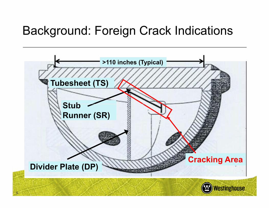
Tubesheet (TS)
Stub
Background: Foreign Crack Indications
>110 inches (Typical)
5
Stub Runner (SR)
Divider Plate (DP)Cracking Area
Background: Foreign Crack Indications
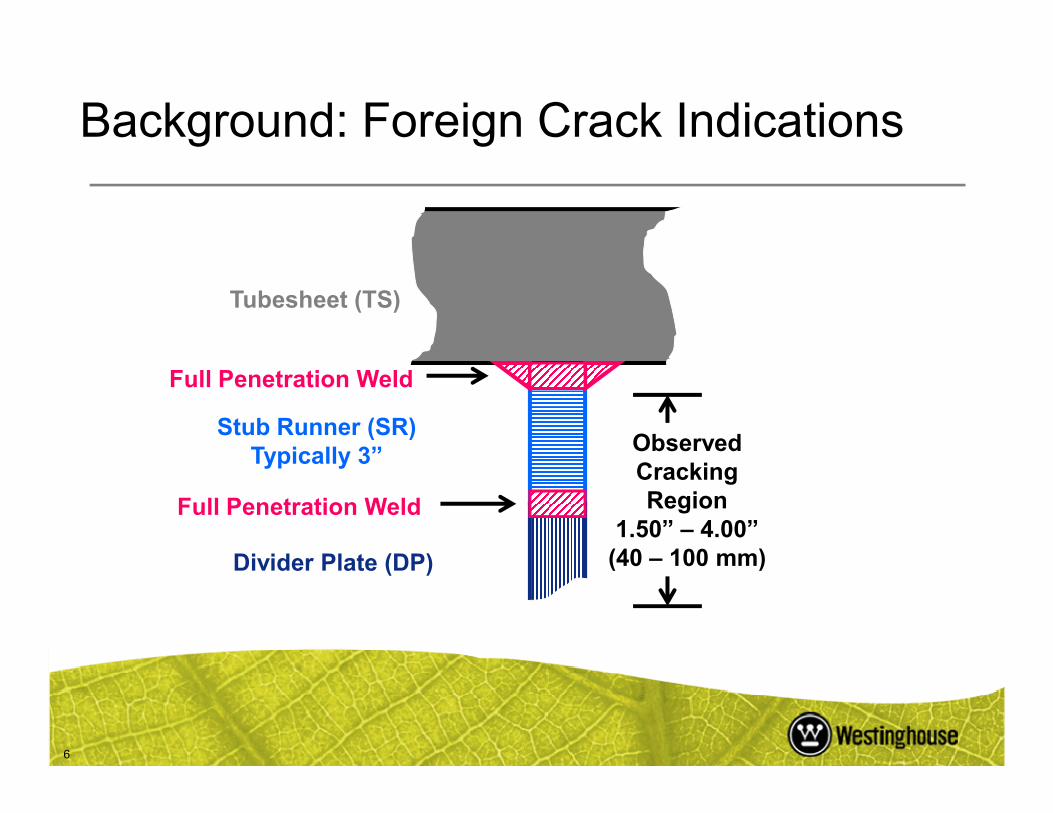
Tubesheet (TS)
Full Penetration Weld
6
Stub Runner (SR)Typically 3”
Divider Plate (DP)
ObservedCrackingRegion
1.50” – 4.00”(40 – 100 mm)
Full Penetration Weld

Background: Foreign Crack Indications
●DP Cracks have been reported in French SG for ~15 years.
●Most cracks are shallow (<<0.10 inch) and short (3 – 8 inches).
7
● A few indications are longer (~70 inches) and deeper (~0.25 inch).– In SG with history of unique events
Background: Foreign Crack Indications
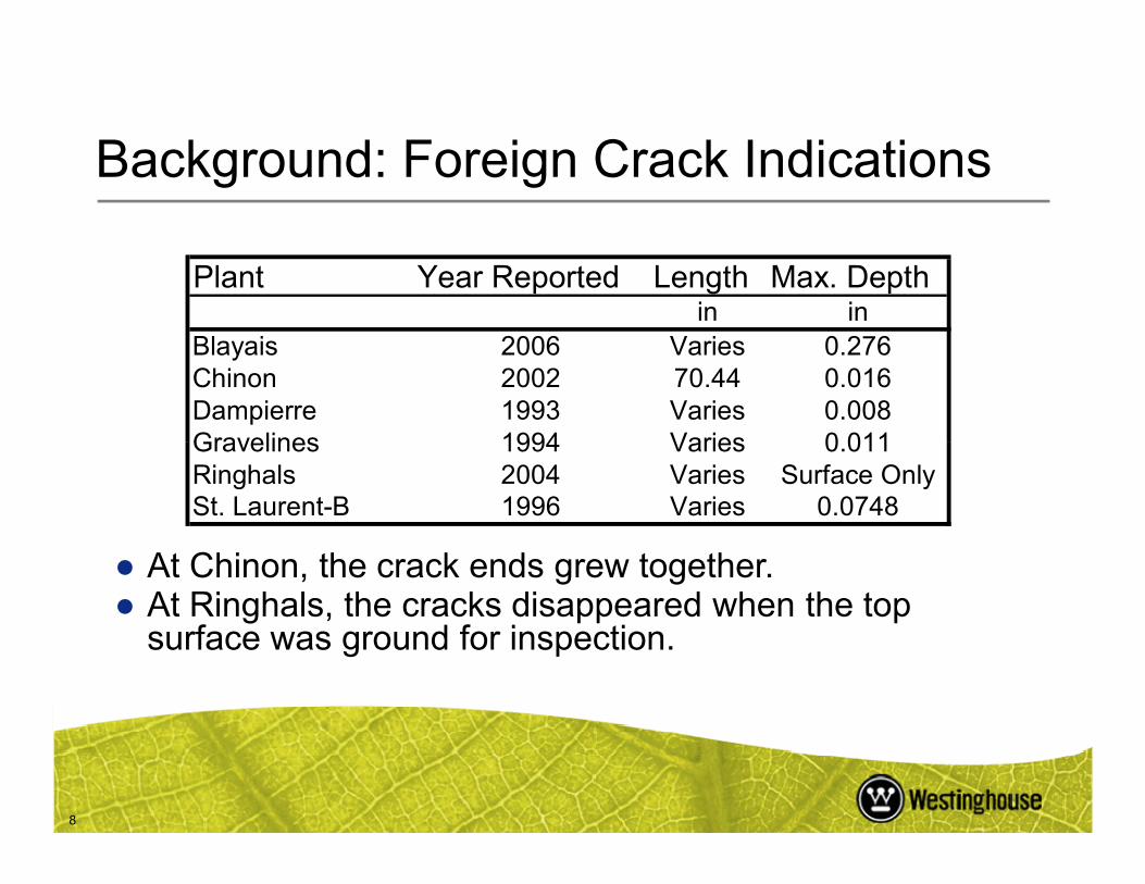
Plant Year Reported Length Max. Depthin in
Blayais 2006 Varies 0.276Chinon 2002 70.44 0.016Dampierre 1993 Varies 0.008Gravelines 1994 Varies 0 011
8
Gravelines 1994 Varies 0.011Ringhals 2004 Varies Surface OnlySt. Laurent-B 1996 Varies 0.0748
● At Chinon, the crack ends grew together.● At Ringhals, the cracks disappeared when the top
surface was ground for inspection.

Background: Crack Indications
●Displacements and stress on the DP come from four (4) sources:– Tension due to pressure drop across TS
– Bending across DP from HL to CL
9
– Thermal growth of CH, TS and DP
– Residual stresses in DP to SR weld and HAZ
● The French plants have a load follow schedule– Load following increases the number of thermal cycles on the
DP and affects fatigue resistance in the weld.

Crack Indication Clusters
Line of SR to DP Weld
Background: Foreign Crack Indications
10
+X Z
Y
Cracks typically oriented along Z-axis
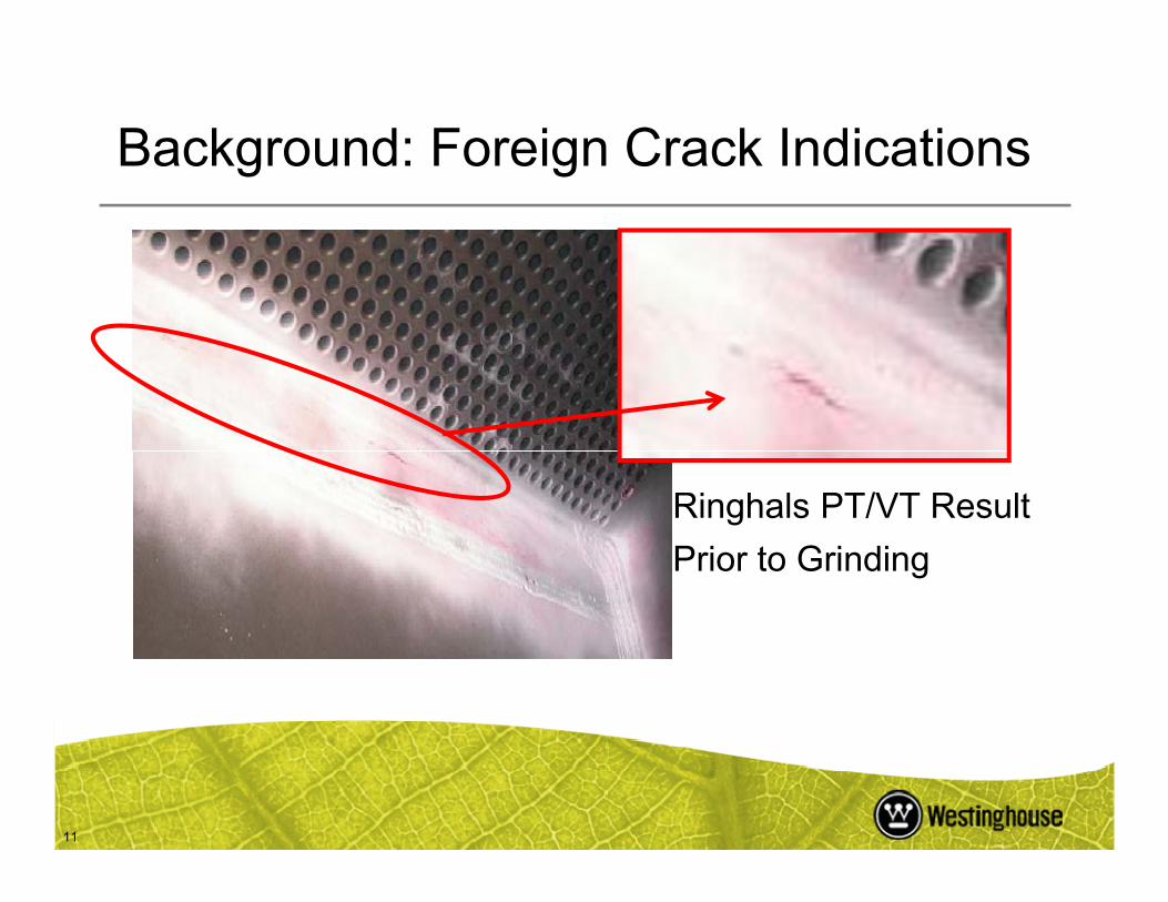
Background: Foreign Crack Indications
11
Ringhals PT/VT Result
Prior to Grinding
Background: Foreign Crack Indications
● The French have been using a combination of auto VT/PT/UT to inspect the DP for cracks
● The VT/PT/UT method resolution limit is 2 mm
●Crack growth is less than 2mm over multiple
12
inspection periods.– Crack growth at Chinon B4 (2002 – 2006)
indicate no change in crack length over multiple inspections.
Domestic Fleet: Summary
●Most SG’s have thicker DP (>1.90 inches)
●Domestic SG’s do not load follow– US DP have different thermal history– Thermal ratcheting, fatigue cycling and other
13
effects more prevalent in load follow conditions● French experience suggests differences in
manufacturing processes– Limited access to French manufacturing records
Domestic Fleet: Summary
● Typical TS-CH complex assembly process:– CH machined and prepared for DP– DP welded to CH– TS machined and prepared for DP
14
– SR welded to TS– Z-seam welds TS and CH together– TS-CH complex heat treated– SR to DP weld applied– SR to DP weld ground flush

Domestic Fleet: Summary
15
Typical Westinghouse TS-CH Complex

Domestic Fleet: Summary
● In the original WEC SG Stress Reports and design analysis:– The DP provides a pressure separation between the HL and
CL of the SG
I i b d
16
– Is not a primary pressure boundary
– TS analysis does not credit the DP
● TS junctions do take credit for the DP to reduce TS displacements– DP to CH connection alone stiffens the CH
– Proposed for Future EPRI work
Domestic Fleet: Summary
● Turkey Point, Byron/Braidwood and Wolf Creek have all received DP related RAI on H*/B* ARC.
● The current H*/B* ARC has been revised so that no credit is taken for the DP to resist vertical or
17
radial displacement of the TS.

Domestic Fleet: Summary
●Combustion Engineering (CE) style SG do not have a structurally connected DP– The DP is installed with set-screws and partial
welds to groove channelsTh t t i CE SG t th TS t th
18
● The center stay in a CE SG connects the TS to the CH directly
●CE SG do not take credit for the DP structurally
●C* is not affected by structural DP issues

Domestic Fleet: Summary
20 in
19
Typical CE Style Divider Plate and Channel Head Assembly
Domestic Fleet: Summary
●DP are currently examined using a bowl camera– There are no qualified US DP inspection
or repair criteria.● There are no qualified US DP inspection tools.
20
– We believe some surface prep may be necessary to inspect the DP
– The surface prep would be dose intensive
Domestic Fleet: Summary
● EPRI conducted an informal survey of DP inspection practices.– Most utilities examine the DP using a visual bowl
scan to look for abnormalities.N h b t d t d t
21
– None have been reported to date.● Some utilities have standards for the DP
examination.
● French style inspection (auto-VT/PT/UT) has not been attempted in the US
EPRI Scoping Study (Phase I): Purpose
1. To determine the limiting model steam generator with respect
to DP cracking.
2. If a DP crack can increase vertical TS displacement by more
than 2%
22
• If the result of a cracked DP is an increase of <2%, then DP
cracking is judged not to be a concern.
3. If a DP crack can propagate 100% through the weld material.
The scoping study was completed in May 2007.

Phase I: Method
● Series of SG model specific 2D finite element analysis (FEA) models to determine limiting SG
●Generic 3D FEA to determine stress and deflection using worst case results
23
●Conservative mechanical fatigue and PWSCC cracking analysis using FEA results
● The contribution of mechanical fatigue and PWSCC to the cracking were varied
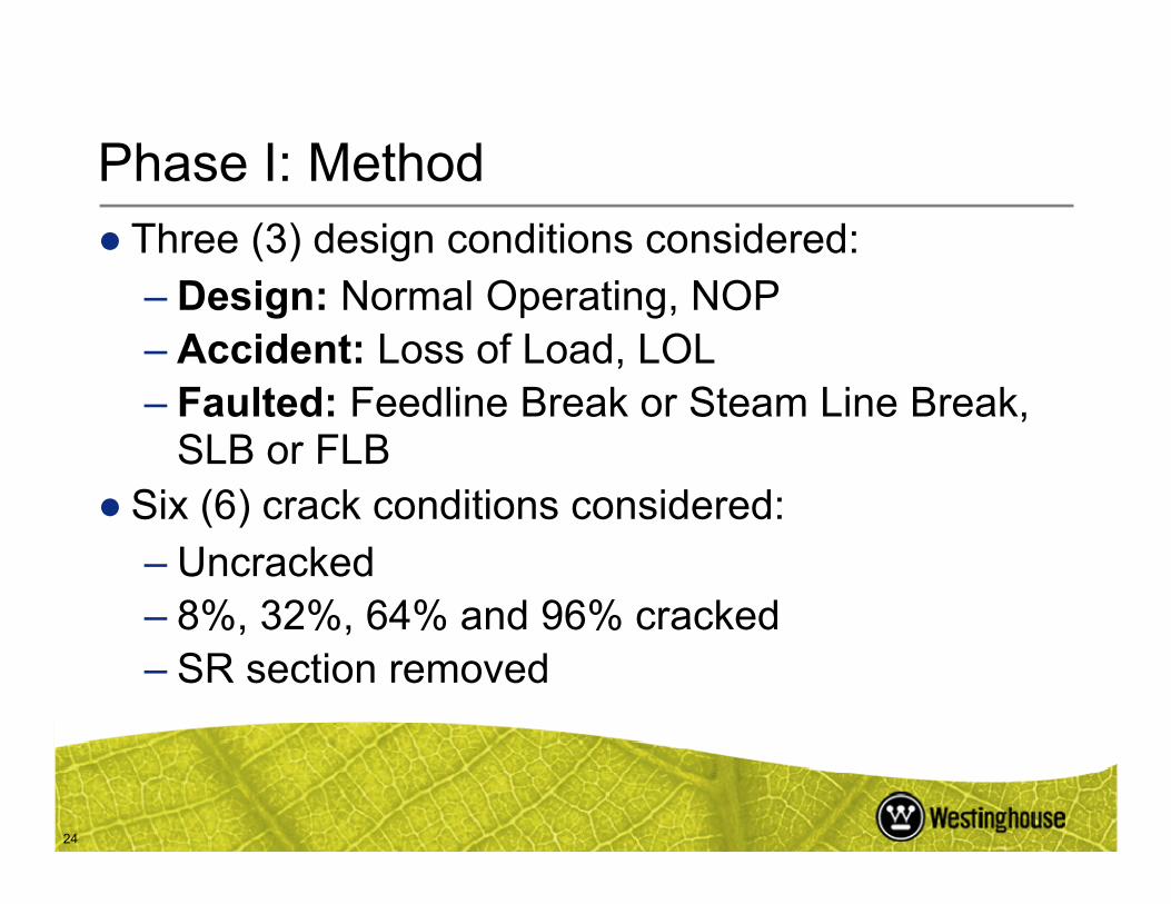
Phase I: Method● Three (3) design conditions considered:
– Design: Normal Operating, NOP– Accident: Loss of Load, LOL– Faulted: Feedline Break or Steam Line Break,
SLB or FLB
24
SLB or FLB● Six (6) crack conditions considered:
– Uncracked– 8%, 32%, 64% and 96% cracked– SR section removed

Phase I: Method
●TS modeled using transversely anisotropic material properties for a perforated structure [Slot].
●Two (2) TS Conditions:
25
–Reinforced by tube material within TS [Terakawa]
–Unmodified TS stiffness
Phase I: Method
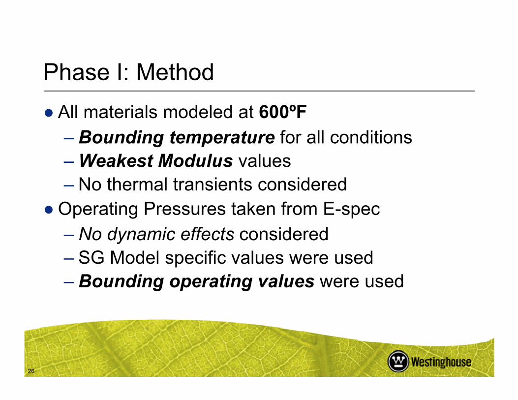
● All materials modeled at 600ºF– Bounding temperature for all conditions– Weakest Modulus values– No thermal transients considered
26
●Operating Pressures taken from E-spec– No dynamic effects considered– SG Model specific values were used– Bounding operating values were used
Phase I: Method
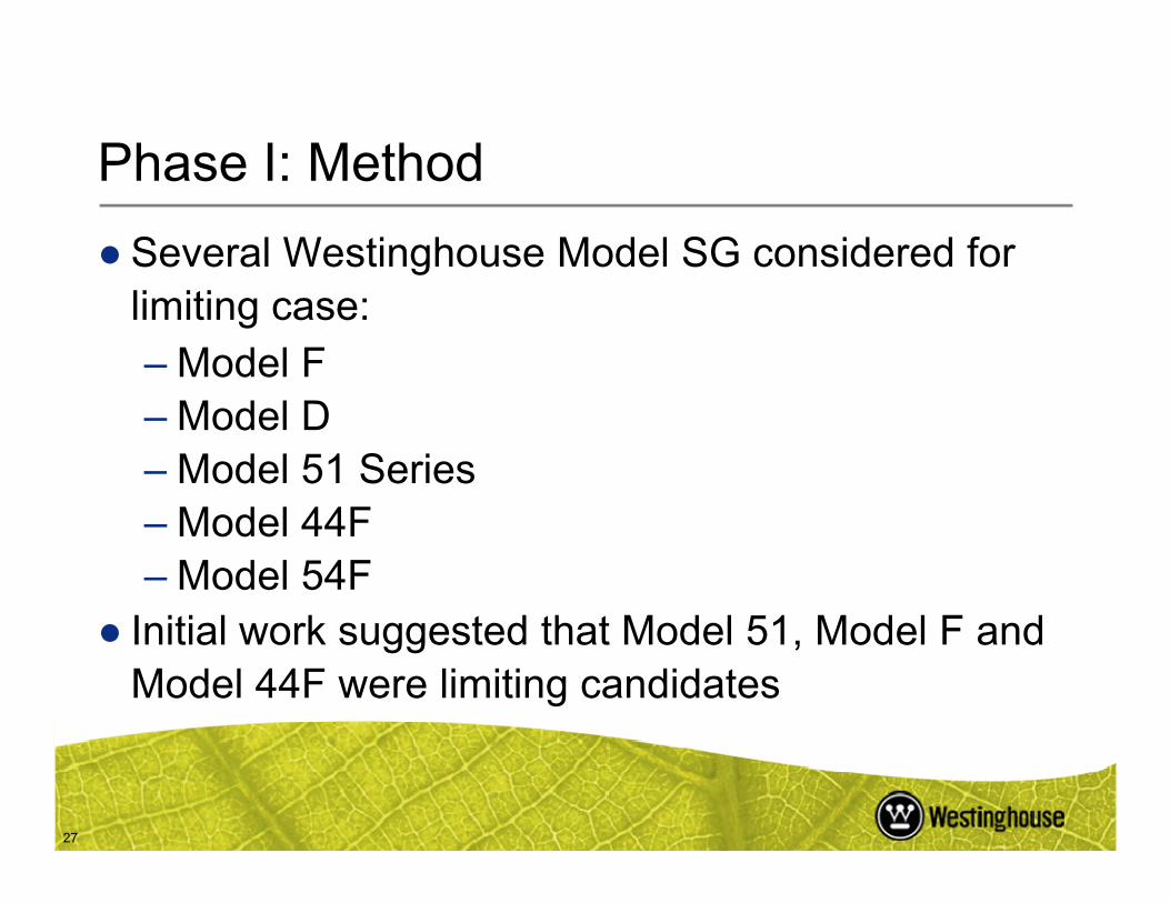
● Several Westinghouse Model SG considered for limiting case:– Model F– Model D
27
– Model 51 Series– Model 44F– Model 54F
● Initial work suggested that Model 51, Model F and Model 44F were limiting candidates

Phase I: MethodModel 51 Parameters
Model 44F Parameters
Category Condition Div. Plate DP Pri. Press Sec. Press. DP Thicknesspsi psi psi in
Design Normal Operating 50 2250 735 1.19Upset Loss of Load 45 2531 695 1.19Faulted Feed Line Break 0 2650 0 1.19
Category Condition Div. Plate DP Pri. Press Sec. Press. DP Thickness
28
Model F Parameters
psi psi psi inDesign Normal Operating 35 2235 770 1.26Upset Loss of Load 35 2735 972 1.26Faulted Feed Line Break 0 2560 0 1.26
Category Condition Div. Plate DP Pri. Press Sec. Press. DP Thicknesspsi psi psi in
Design Normal Operating 50 2272 870 1.90Upset Loss of Load 45 2663 1221 1.90Faulted Feed Line Break 0 2560 0 1.90

Phase I: Method
29
•Sharp edged crack geometry•Higher order elements to capture crack growth
Phase I: Method
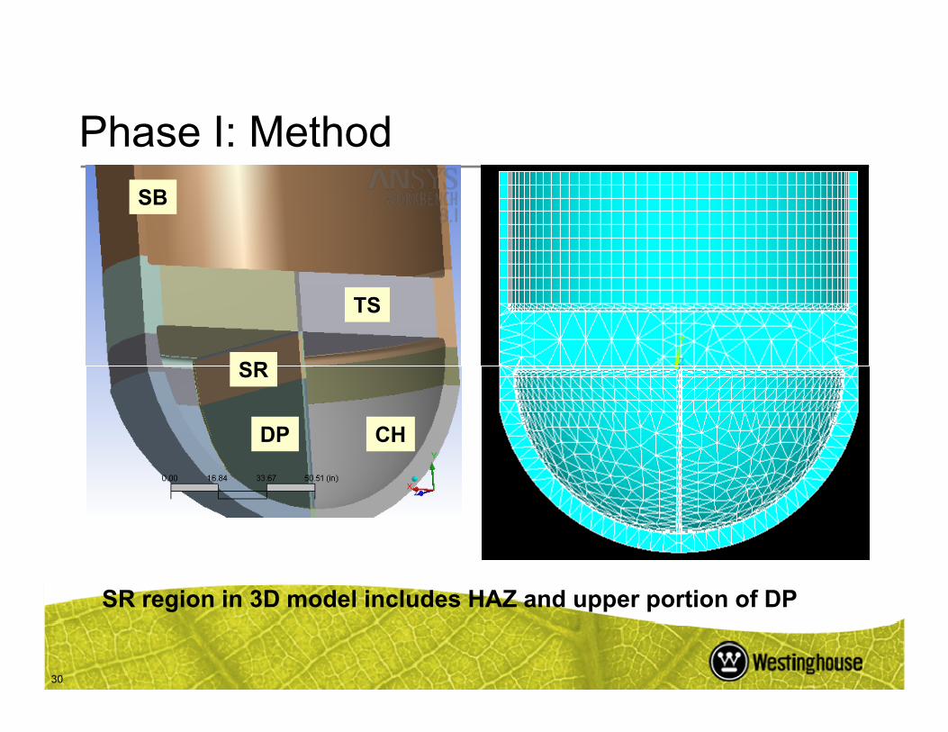
TS
SR
SB
30
CHDP
SR
SR region in 3D model includes HAZ and upper portion of DP

Phase I: Method
31
Typical Boundary Conditions in 3D FEA Model

Phase I: MethodApplied Tensile Displacement
•Crack geometry in study is conservative.•Cracks between CH and DP were not considered in the analysis.R l k ld b
32
Crack Growth into the plate thickness
Phase I Model Crack Geometry
•Real cracks would be branched.•Real cracks would grow in 3D, not 1D.
Phase I: Assumptions
● Failure of the weld in the study is defined as a crack extending 100% of the plate length and 100% of the plate depth.– Plastic yielding of the weld can occur before
l t ld f il
33
complete weld failure.– A DP with a completely failed SR to DP weld
can still bear pressure from HL and CL chambers of the CH.
Phase I: AssumptionsPhase I used very conservative assumptions, such as:
● The entire DP/SR weld surface was cracked (100%).
● A uniform crack front exists.●No threshold for PWSCC initiation
34
●No threshold for PWSCC initiation.●No decrease in crack growth rate from residual
stress effects.●Homogenous weld material.● 4.5 ksi-in0.5 fatigue crack threshold
Phase I: Assumptions
● Minimum dimensional tolerances on all machined
components.
● Maximum material corrosion loss on all secondary
surfaces.
35
● 1503 applied design transient events each calendar year.
● Full load reversal at maximum ΔP for calculating
mechanical fatigue effects.
● Worst case 2D stiffness result from limiting SG applied to
typical SG 3D model.
Phase I: Assumptions
40
60
80
100
120
140
rack
Gro
wth
Rat
e [E
-10
in/s
ec]
EdF Model
36
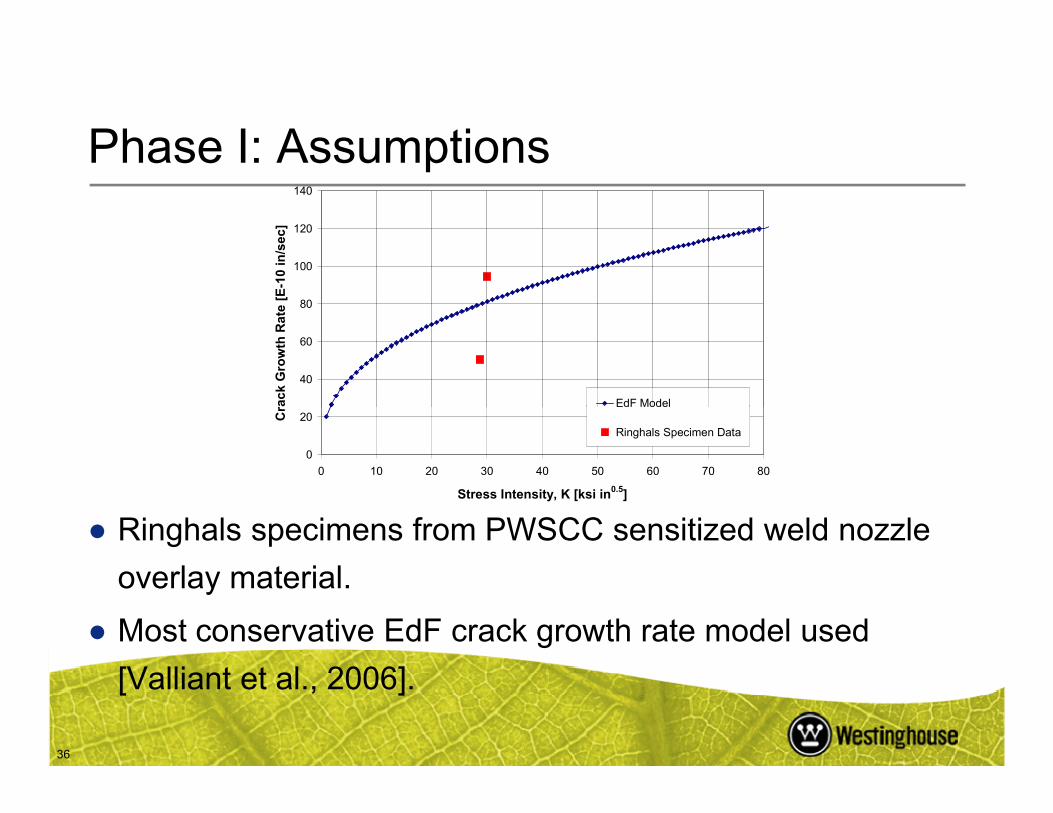
● Ringhals specimens from PWSCC sensitized weld nozzle
overlay material.
● Most conservative EdF crack growth rate model used
[Valliant et al., 2006].
0
20
0 10 20 30 40 50 60 70 80
Stress Intensity, K [ksi in0.5]
Cr d ode
Ringhals Specimen Data
Phase I: Model 51 Comparison
●Model 51 comparison of TS displacements with and without a DP present.
●Original Model 51 Stress Report analysis used FEA and scale models
37
● The purpose of the original study was to verify plastic limit load conditions in the TS and CH.
● The scale model and original FEA did not include a DP.
Phase I: Model 51 Comparison
● The original FEA predicted vertical deflection of ~0.469 inch at the center of the TS.
● The measured radial strain at the center of the TS in the scale model at 2410 psid was 0.359%. The measured deflection was 0.530 inch.
38
● It was assumed that not taking credit for the CH to DP connection was highly conservative.
Phase I: Model 51 Comparison
● In the updated FEA model, for a TS with a DP but no SR, at 2410 psid:– The radial strain is 0.034%.– The vertical displacement is ~0.035 inch.
● The presence of the DP reduced the deflection and strain by an order of magnitude without the SR present
39
by an order of magnitude, without the SR present.● The majority of the stiffening effect of the DP comes from
the DP to CH connection, not the DP to TS connection.
– This validates the assumption about the DP to CH connection.
Phase I: Results
●Westinghouse Model 51 SG is the limiting case– Thinnest DP section (1.19 inches)– Designed with SR– Largest vertical TS displacements
40
– Similar design to French SG with cracked DP●Model 44F was the next worst case
● Stiffness of tubes within TS not significant.– Due to crack geometry.

Phase I: Results
Displacement Results Magnified 100x
TS displacement not significant until cracking is >64%.
41
NOP, 8% Cracked, Vert. Displacement NOP, 64% Cracked, Vert. Displacement
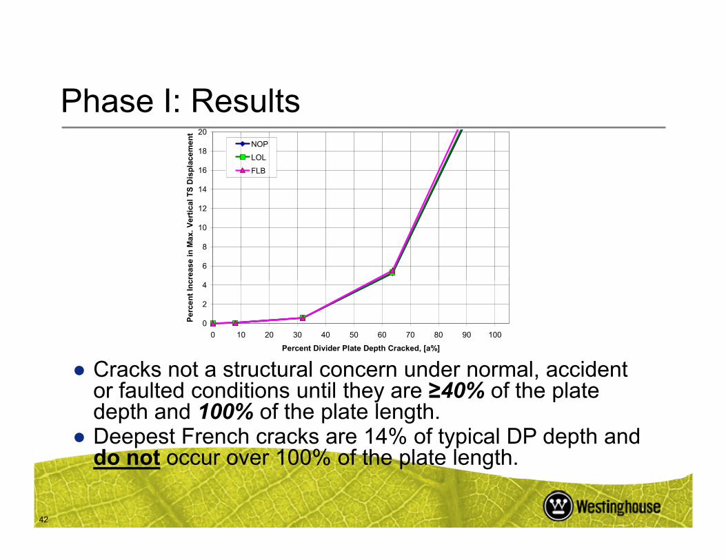
Phase I: Results
6
8
10
12
14
16
18
20
crea
se i
n M
ax.
Ver
tica
l TS
Dis
pla
cem
ent
NOP
LOL
FLB
42
0
2
4
0 10 20 30 40 50 60 70 80 90 100
Percent Divider Plate Depth Cracked, [a%]
Per
cen
t In
c
● Cracks not a structural concern under normal, accident or faulted conditions until they are ≥40% of the plate depth and 100% of the plate length.
● Deepest French cracks are 14% of typical DP depth and do not occur over 100% of the plate length.
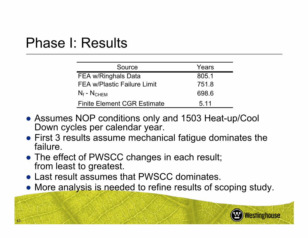
Phase I: Results
Source YearsFEA w/Ringhals Data 805.1FEA w/Plastic Failure Limit 751.8Nf - NCHEM 698.6
Finite Element CGR Estimate 5.11
● Assumes NOP conditions only and 1503 Heat-up/Cool
43
● Assumes NOP conditions only and 1503 Heat-up/Cool Down cycles per calendar year.
● First 3 results assume mechanical fatigue dominates the failure.
● The effect of PWSCC changes in each result;from least to greatest.
● Last result assumes that PWSCC dominates. ● More analysis is needed to refine results of scoping study.

Phase I: Results
Years # in ksi in0.5 ksi in0.5E-10 in/sec in/cycle in in
1 1503 0.16 15.76 15.76 62.82 1.378E-05 0.22 0.382 3006 0.16 23.83 23.83 74.12 4.763E-05 0.54 0.705 7515 0.16 30.72 30.72 82.61 1.020E-04 1.76 1.92
Avg. Final K
PWSCC CGR Fatigue CGRΔKTimeFinal Crack
LengthEstimated
nInitial Crack
LengthChange in
Crack Length
Model 51 Crack Growth Rate Summary
44
● A crack in PWSCC sensitized weld could grow through the DP in 5.11 years.– Assumes no threshold for crack growth
6 9018 0.16 48.79 48.79 98.72 4.087E-04 2.48 2.64

Phase I: Results
●Using highly conservative assumptions:– DP cracks can grow under NOP conditions– The analysis suggests that a combination of
PWSCC and mechanical fatigue could fail the weld in time
45
weld in time.– The currently observed crack indications do not
result in a structural concern under normal or accident conditions.
– The cracks must be very large (deep and long) to increase TS displacement >2%.
Phase I: Results
● 93% of the depth and 100% of the length of the DP thickness must be cracked to fail during FLB– Analysis predicts plastic yielding
● After ~15 years, the Foreign SG have not
46
approached the 2% TS deflection increase limit.
●More analysis is planned to refine scoping study.

Domestic Fleet: Conclusions
●Current tube/TS related ARC have been revised so that no credit is taken for the DP.
●More analysis is planned to determine if there is an effect on other structures because of a
47
degraded DP.– Phase II of the EPRI program is being
developed.
The Role of the Divider Plate in the H*/B* ARC Analysis
● In H*/B* WCAPs prior to 2006 the DP is assumed to provide some restraint to vertical and radial TS deflections.
●Restricting vertical TS deflections limits the radial deflection of the TS because the rotation of the TS
48
due to bowing is reduced.●Radial deflections are used in the calculation of TS
hole dilation.

Recent H*/B* Divider Plate RAI
17. Reference 2, Enclosure 1, Attachment 1 (The Westinghouse Letter Summary of Changes to B* and H*), page 14 - address the status of the divider plate evaluation being performed under EPRI sponsorship, and the schedule for completion of the various topics being addressed in the evaluation. Describe any inspections that have been performed domestically that provide insight on whether the extent and severity of
49
y p g ydivider plate cracks is bounded by the foreign experience. Discuss the available options for inspecting the divider plates.

Planned Response to RAI 17
● Phase I of the EPRI study is complete.– EPRI technical report 1014982
● Phase II of the study is being developed.– Is inspection of the DP required?
50
●General visual examination of the DP is conducted at some plants.– No large abnormalities have been observed.– There are currently no other viable domestic DP
inspection methods.

Recent H*/B* Divider Plate RAI
18. Discuss how the ability of the divider plates at Plant A to resist tubesheet deflection (without failure) under operating and accident loads is assured in the short term, pending completion of the EPRI evaluation. Include in this discussion the actions that are planned in the near term to ensure that the divider plates are capable of resisting tubesheet deflection.
51

Planned Response to RAI 18
● EDF has concluded that the DP to SR cracks do not grow.– None of the cracking indications to date have
exceeded depth necessary to cause an increase of more than 2% TS deflection
52
of more than 2% TS deflection.● The DP to CH weld, alone, is capable of limiting
the TS deflection.– The DPF for the case of a DP to CH connection
only is 0.64.

Planned Response to RAI 18, Cont’d.
● There have been no observed indications in the DP to CH weld:– The DP to CH weld is heat treated.
●Most Domestic SG have DP that are thicker than
53
the French DP.
●Domestic SG do not load follow:– Fatigue usage factor in domestic DP is expected
to be lower than French DP.● The worst French cracking is associated with
anomalies.
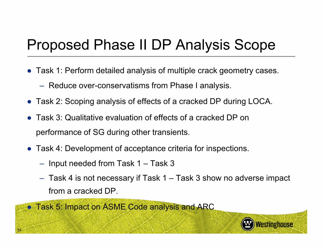
Proposed Phase II DP Analysis Scope
● Task 1: Perform detailed analysis of multiple crack geometry cases.
– Reduce over-conservatisms from Phase I analysis.
● Task 2: Scoping analysis of effects of a cracked DP during LOCA.
● Task 3: Qualitative evaluation of effects of a cracked DP on
54
performance of SG during other transients.
● Task 4: Development of acceptance criteria for inspections.
– Input needed from Task 1 – Task 3
– Task 4 is not necessary if Task 1 – Task 3 show no adverse impact
from a cracked DP.
● Task 5: Impact on ASME Code analysis and ARC

The Divider Plate Factor
●Westinghouse ARC originally assumed that the DP could reduce the displacement of the TS.
●Original H* and B* analyses take credit for the DP.
●H* and B* have been revised to exclude
55
the DP from analysis results.– Removes DP from any consideration; DP to TS
and DP to CH connections eliminated.

The Divider Plate Factor
● The original DP analysis showed that TS displacements were reduced by 24% with a fully functioning as-designed DP.
● This led to using a DP factor (DPF) of 0.76 to scale TS displacements.
●Recent analysis shows that TS displacements are
56
●Recent analysis shows that TS displacements are reduced by nearly 60% with a fully intact DP in a detailed model of the TS-CH Complex.
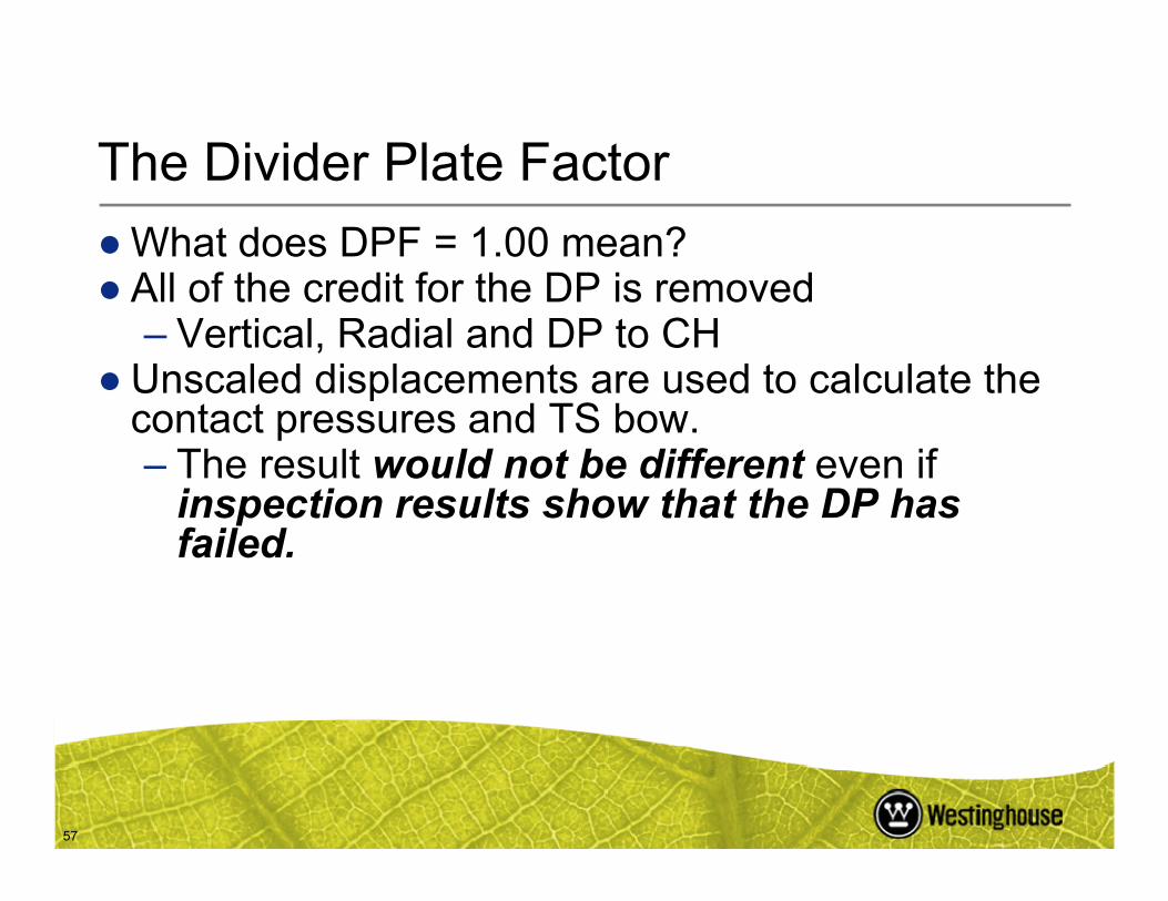
The Divider Plate Factor
●What does DPF = 1.00 mean? ● All of the credit for the DP is removed
– Vertical, Radial and DP to CH ●Unscaled displacements are used to calculate the
contact pressures and TS bow.Th lt ld t b diff t if
57
– The result would not be different even if inspection results show that the DP has failed.
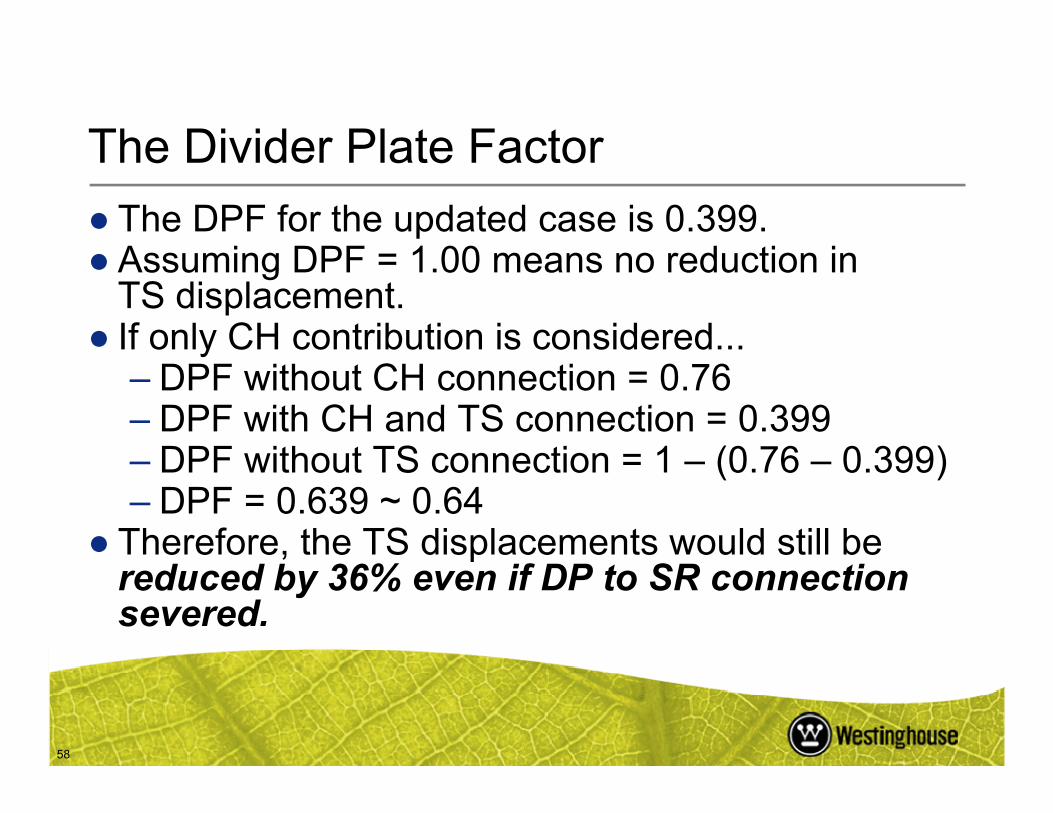
The Divider Plate Factor
● The DPF for the updated case is 0.399.● Assuming DPF = 1.00 means no reduction in
TS displacement.● If only CH contribution is considered...
– DPF without CH connection = 0.76DPF ith CH d TS ti 0 399
58
– DPF with CH and TS connection = 0.399– DPF without TS connection = 1 – (0.76 – 0.399)– DPF = 0.639 ~ 0.64
● Therefore, the TS displacements would still bereduced by 36% even if DP to SR connection severed.
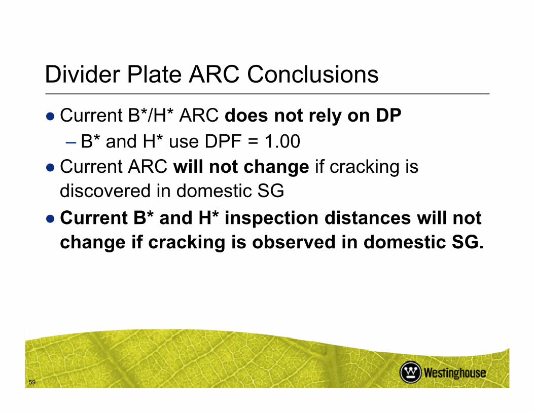
Divider Plate ARC Conclusions
●Current B*/H* ARC does not rely on DP– B* and H* use DPF = 1.00
●Current ARC will not change if cracking is discovered in domestic SG
59
●Current B* and H* inspection distances will not change if cracking is observed in domestic SG.
NRC Comments and Questions
60


