9 VG9H 20 EN • 12/2010 NELES VALVGUARD VG9000H INTELLIGENT SAFETY VALVE CONTROLLER Neles ValvGuard™ VG9000H is a new generation safety valve controller and partial stroke test device for emergency shutdown (ESD) or emergency venting (ESV) valves. It's unique and advanced functions and features are specially designed for emergency valve controllers. Together with HART communication it offers unbeatable value for our customers with increased efficiency, reliability and safety. VG9000H is IEC 61508 compliant up to SIL 3. Based on the automatic partial stroke testing (PST) and other diagnostics data, VG9000H increases safety and plant safety targets can be reached more economically than with traditional solutions. Also, unnecessary and expensive manual testing can be avoided. This increases safety and can simultaneously create major cost savings at a plant. VG9000H is operated by 4-20mA signal and the diagnostics part of the safety valve controller can be alive all the time. This is a true user benefit and gives maximum availablity of the diagnostics information. VG9000H is thus capable to record emergency trips with graph and keyfigures related to it. The availability of the safety valves is maximized through unique diagnostics features, directly integrated into device functionality. Diagnostic information is presented in easily understandable form by using graphical FDT/ DTM user interface, such as Metso FieldCare™. This enables the predictive maintenance of potentially failing valve assemblies before they have chance to impact on the process. KEY FEATURES □ Valve and self tests □ Partial stroke test (automatic or manual) □ Self test for internal electronics and pneumatics □ Emergency trip test □ High pneumatic capacity eliminates the need of additional instumentation in most cases □ Device is powered during the trip and can collect diagnostics information □ Easy of use local / remote operation □ Advanced device diagnostics including □ Self-diagnostics □ Online diagnostics □ Performance diagnostics □ HART communication Open solution □ Metso is committed to delivering products that freely interface with software and hardware from a variety of manufacturers. This open architecture allows the Valv- Guard to be integrated with other field devices and systems. □ FDT based multi-vendor support configuration □ The different support files for VG9000H are available in the internet, at http://www.metso.com/valves TÜV Certificate Neles ValvGuard VG9000H is TÜV approved to be used in safety applications up to and including safety integrity level 3 (SIL 3).
Neles ValvGuard™ VG9000H is a new generation safety valve controller and partial stroke test device for emergency shutdown (ESD) or emergency venting (ESV) valves. It's unique and advanced functions and features are specially designed for emergency valve controllers. Together with HART communication it offers unbeatable value for our customers with increased efficiency, reliability and safety. VG9000H is IEC 61508 compliant up to SIL 3. Based on the automatic partial stroke testing (PST) and other diagnostics data, VG9000H increases safety and plant safety targets can be reached more economically than with traditional solutions. Also, unnecessary and expensive manual testing can be avoided. This increases safety and can simultaneously create major cost savings at a plant. VG9000H is operated by 4-20mA signal and the diagnostics part of the safety valve controller can be alive all the time. This is a true user benefit and gives maximum availablity of the diagnostics information. VG9000H is thus capable to record emergency trips with graph and keyfigures related to it. The availability of the safety valves is maximized through unique diagnostics features, directly integrated into device functionality. Diagnostic information is presented in easily understandable form by using graphical FDT/DTM user interface, such as Metso FieldCare™. This enables the predictive maintenance of potentially failing valve assemblies before they have chance to impact on the process.
KEY FEATURES□ Valve and self tests
□ Partial stroke test (automatic or manual)□ Self test for internal electronics and pneumatics□ Emergency trip test
□ High pneumatic capacity eliminates the need ofadditional instumentation in most cases
□ Device is powered during the trip and can collectdiagnostics information
□ Easy of use local / remote operation□ Advanced device diagnostics including
Open solution□ Metso is committed to delivering products that freely
interface with software and hardware from a variety ofmanufacturers. This open architecture allows the Valv-Guard to be integrated with other field devices andsystems.
□ FDT based multi-vendor support configuration □ The different support files for VG9000H are available in
the internet, at http://www.metso.com/valves
TÜV CertificateNeles ValvGuard VG9000H is TÜV approved to beused in safety applications up to and including safetyintegrity level 3 (SIL 3).
10
M E T S O
2
9 V G 9 H 2 0 E N
Options□ High pneumatic capacity□ Remote Communication Interface (RCI9H) for 24 VDC ret-
rofit installations. (See type coding for RCI9H option)□ Integrated limit switches□ Local Control Panel (LCP9H). (See type coding for LCP9H
option) □ Language selection: English, German and French
Lower total cost of ownership□ Automised valve testing and testing documentation□ Low energy and air consumption□ Future proof design allows further options at a reduced
cost
Easy installation and configuration□ Same unit for linear and rotary valves, double and single-
acting actuators□ Simple calibration and configuration
- Using local user interface- Using Metso FieldCare or any FDT compliant software ina remote location
Easy to maintain□ Optimised spares program. Reduced number of spares□ Fewer maintainable components than in a traditional
instrumentation solution□ Ability to attach options to mechanics later□ Visibility to the safety valve operation
Mounting□ Can be mounted on single and double acting pneumatic
actuators□ Can be mounted on both rotary and linear valves□ Extensive selection of mounting kits for 3rd party actua-
tors
Product reliability□ Designed to operate in harsh environmental conditions
□ Rugged modular design□ Excellent temperature characteristics□ Vibration and impact tolerant□ IP66 enclosure□ Protected against humidity□ Full 316 stainless steel version available, see technical
bulletin 9VG93H20EN □ Maintenance free operation
□ Resistant to dirty air□ Wear resistant and sealed components□ Contactless position measurement
Predictive maintenance□ Easy access to collected data with Metso FieldCare software
□ Logical trend collection□ Information collected on service conditions□ Fast notifications with on-line alarms□ Condition monitoring tool available
TECHNICAL DESCRIPTIONNeles ValvGuard VG9000H is a 4-20 mA loop-poweredmicrocontroller-based intelligent safety valve controller andpartial stroke test device with HART communication. Thedevice stays alive even at 3.7 mA input signal and communi-cates via HART. Optional RCI unit is required if the safety sys-tem output is binary (DO) 24 V DC. The device contains a Local User Interface enabling localconfiguration. A PC with Metso FieldCare software can beused for advanced configuration and diagnostics.The powerful 32-bit microcontroller controls the valve posi-tion during partial stroke and other special testing.The measurements include:□ Input signal□ Valve position with contactless sensor□ Actuator pressures, two independent measurements□ Supply pressure□ Device temperatureAdvanced self-diagnostics ensures that all measurementsoperate correctly. Failure of any measurement does notcause the valve to go to fail-safe position. Operating priciple of VG9000H is based on pneumatic sole-noid valve (SV) and prestage (PR) which is controlled bymicrocontroller (μC). Information from the various sensors isused for the operation.
Fig. 1 The principle of operation
TECHNICAL BULLETIN 12/10
N E L E S V A L V G U A R D V G 9 0 0 0 H I N T E L L I G E N T S A F E T Y V A L V E C O N T R O L L E R9 V G 9 H 2 0 E N
TECHNICAL SPECIFICATIONS
Neles ValvGuard VG9000H
GeneralLoop powered, no external power supply required.Suitable for rotary and linear valves.Actuator connections in accordance with VDI/VDE 3845 andIEC 60534-6 standards.Action: Double or single actingTravel range: Linear: 10–120 mm
Rotary: 45–95°Measurement range 110° with freelyrotating feedback shaft
Environmental influenceStandard temperature range:
-20° to +85 °C / -4° to +185 °FInfluence of vibration on valve position
under 2g 5–150 Hz,1g 150–300 Hz, 0.5g 300–2000 Hz
Open and closed position: no effect
Enclosure Material: Anodised aluminium alloy and
glass windowProtection class: IP66, NEMA 4XPneumatic ports: VG9215 1/4 NPT
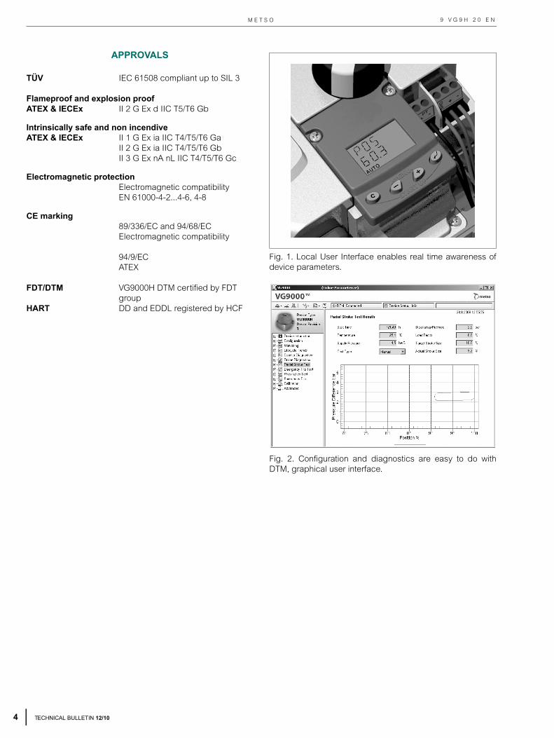
CE marking89/336/EC and 94/68/ECElectromagnetic compatibility
94/9/ECATEX
FDT/DTM VG9000H DTM certified by FDT group
HART DD and EDDL registered by HCF
Fig. 1. Local User Interface enables real time awareness ofdevice parameters.
Fig. 2. Configuration and diagnostics are easy to do withDTM, graphical user interface.
TECHNICAL BULLETIN 12/10
N E L E S V A L V G U A R D V G 9 0 0 0 H I N T E L L I G E N T S A F E T Y V A L V E C O N T R O L L E R
5
9 V G 9 H 2 0 E N
TECHNICAL BULLETIN 12/10
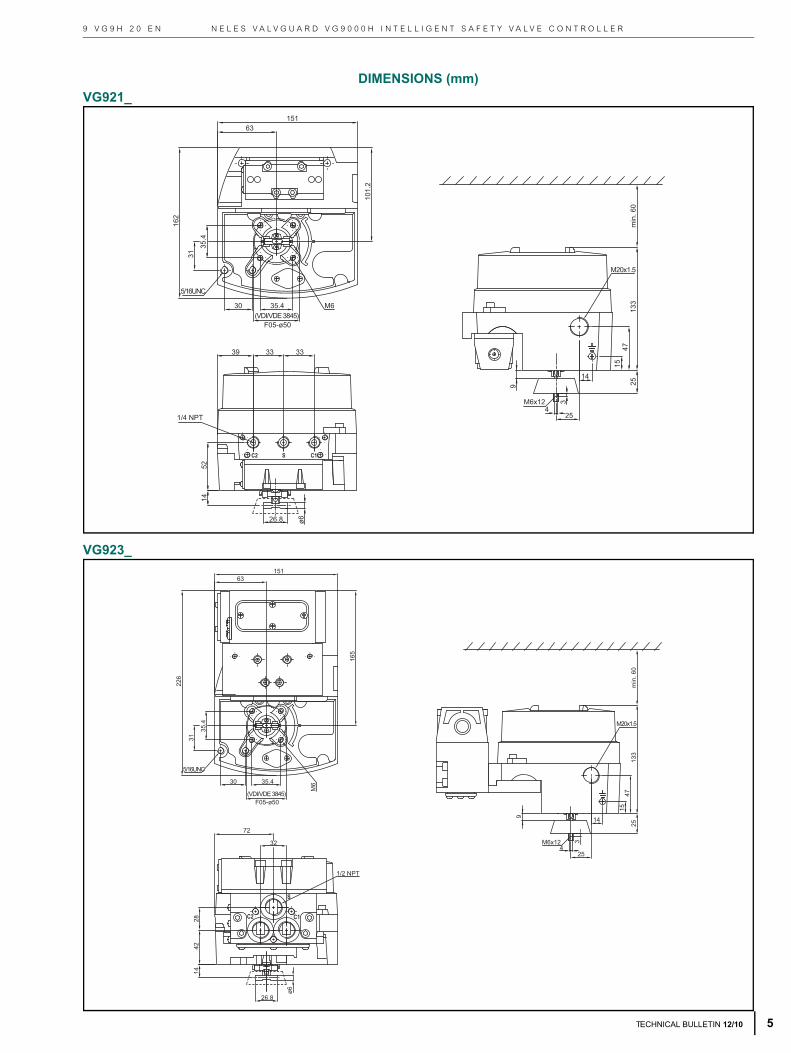
DIMENSIONS (mm)VG921_
VG923_
35.4 M630
31
5/16UNC
14
15
25
4725
133
M20x1.5
M6x124
3
1/4 NPT
33 3339
35.4
162
63151
101.
2
F05-ø50(VDI/VDE 3845)
5214
26.8 ø6
9
min
. 60
5/16UNC
31
35.4
35.430
M6x12 3
425
14
1547
133
M20x1.5
9
1/2 NPT
4228
14
ø6
26.8
226
15163
165
F05-ø50(VDI/VDE 3845)
M6
72
32
25m
in. 6
0
M E T S O
6
9 V G 9 H 2 0 E N
VG921_/I00
VG923_/I00
2630
5/16UNCx13
31
F05- 50(35.4)
M6x10
3933
33
14.5
26.8
1/4NPT
VDI/VDE 3845
ø6
62
4795
25
190
M20x1.5
103174
6316
1
min
. 60
25
47
2630
5/16UNCx13
31
F05- 50(35.4)
M6x1014.5
26.8
VDI/VDE 3845
63
151
ø6
62
M20x1.5
32
42.4 28
72
167
190
161
239
min
. 60
TECHNICAL BULLETIN 12/10
N E L E S V A L V G U A R D V G 9 0 0 0 H I N T E L L I G E N T S A F E T Y V A L V E C O N T R O L L E R9 V G 9 H 2 0 E N
HOW TO ORDER
NELES VALVGUARD VG9000H
*) Slash shall always be marked in places shown above.
1. 2. 3. 4. 5. 6. 7. 8. 9.VG 9 2 15 H E6 / I02
1. sign PRODUCT GROUP
VG Neles ValvGuard VG9000H, Intelligent Safety Valve Controller.TÜV SIL 3 certified according to IEC 61508 .
2. sign SERIES CODE
9
Series 9000 Intelligent safety valve controller with universal shaft and attachment face according to standard VDI/VDE 3845. Relevant shaft adapter included in mounting kits. *) When safety valve controllers are separate deliveries, shaft adapter kit is supplied.
3. sign ENCLOSURE
2Standard IP66 / NEMA 4X enclosure.Standard temperature range -20 to +85 °C / -4 to +185 °F. 1 pcs M20x1.5 conduit entry.
4. sign SPOOL VALVE CONNECTIONS
15 Standard capacityStroke volume of actuator < 13 dm3 S, C1, C2 = 1/4 NPT
35 High capacityStroke volume of actuator > 13 dm3
S, C1, C2 = 1/2 NPT
37 Extended capacity For single acting actuators
S = 1/2 NPT, C2 = 1 NPT
5. sign COMMUNICATION / INPUT SIGNAL RANGEH 4-20 mA, HART communication.
6. sign APPROVALS FOR HAZARDOUS AREAS
N No approvals for hazardous areas.
X1
ATEX & IECEx certifications: II 1 G Ex ia IIC T4/T5/T6 Ga
VG9_HX1:Ui ≤ 28 V, Ii ≤ 120 mA, Pi ≤ 1.0 W, Li ≤ 53 μH, Ci ≤ 9.6 nF.Temperature range: T4; -20 – +80 °C / -4 – +176 °F,T5; < +65 °C / < +149 °F, T6; < +50 °C / < +122 °F.Not available with limit switches.
X2
ATEX & IECEx certifications:II 2 G Ex ia IIC T4/T5/T6 Gb
VG9_HX2: Ui ≤ 28 V, Ii ≤ 120 mA, Pi ≤ 1.0 W, Li ≤ 53 μH, Ci ≤ 8 nF.Temperature range: T4; -20° – +80 °C / -4°– +176 °F,T5; < +65 °C / +149 °F, T6; < +50 °C / +122 °F.Only available with ATEX certified inductive limit switches (e.g. I02, I09).
X3
ATEX & IECEx certifications:II 3 G Ex nA nL IIC T4/T5/T6 GcNo Zener Barrier needed.Ui ≤ 30 V, Ii ≤ 152 mA, Pmax = device limits itself.
VG9_HX3:Temperature range: T4; -20 – +85 °C / -4 – +185 °F,T5; < +75 °C / +167 °F, T6; < +60 °C / +140 °F.Available without limit switches or with ATEX certified inductive limit switches (e.g. I02, I09)
E6
ATEX & IECEx certifications:II 2 G Ex d IIC T5/T6 Gb
VG9_HE6: Ui ≤ 30 VTemperature range: T5; -20° – +80 °C / -4° – +176 °FT6; -20° – +70 °C / -4° – +158 °FAvailable with or without limit switches.
7. sign OPTIONS OF SAFETY VALVE CONTROLLER
T
VG9_H_T only: Internal 2-wire (passive) position transmitter.Analog position feedback signal, output 4-20 mA, supply voltage 12 - 30 VDC,external load resistance 0 – 780 Ω.
VG9_HX1T and VG9_HX2T: Ui ≤ 28 V, Ii ≤ 120 mA, Pi ≤ 1.0 W, Li ≤ 53 μH, Ci ≤ 8 nF.
NOTE: Only 1 pcs M20x1.5 conduit entry in the standard enclosure, use 7. sign "J" or "L1" if additional conduit entries are required.
J
External junction box for all 4-20 mA wirings, including position transmitter, if applicable. Junction box is located in the standard enclosure, 2 pcs M20x1.5 conduit entry.Not applicable to 7. sign "L1"NOTE: This option must be selected if both 7. sign "L2" (for Local Control Panel LCP9H) and 8. sign (limit switches) are selected.
L1
Extension housing with additional conduit entries, 2 pcs M20x1.5.Applicable to Position Transmitter, 7. sign "T", if additional conduit entry is required.Not applicable to 7. sign "J", "L2" or limit switches (8.sign).
L2
Extension housing with additional conduit entries, 2 pcs M20x1.5 for Local Control Panel (LCP9H).Not applicable to 7. sign "L1".NOTE: 7. sign "J" needs to be selected also if limit switches are specified.Local Control Panels LCP9H_ need to be specified separately!
Y Special construction, to be specified.
TECHNICAL BULLETIN 12/10 7
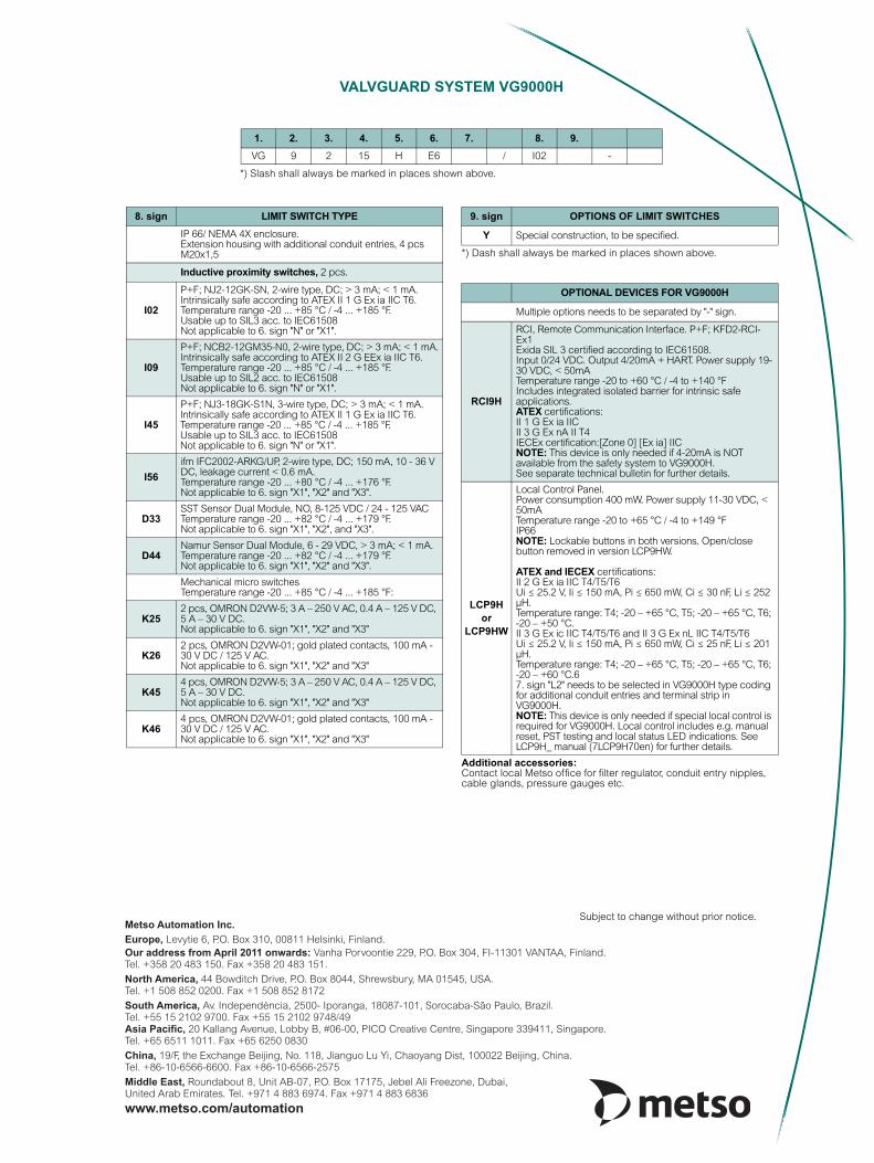
VALVGUARD SYSTEM VG9000H
*) Slash shall always be marked in places shown above.
1. 2. 3. 4. 5. 6. 7. 8. 9. VG 9 2 15 H E6 / I02 -
*) Dash shall always be marked in places shown above.
Additional accessories:Contact local Metso office for filter regulator, conduit entry nipples, cable glands, pressure gauges etc.
8. sign LIMIT SWITCH TYPEIP 66/ NEMA 4X enclosure.Extension housing with additional conduit entries, 4 pcs M20x1,5
Inductive proximity switches, 2 pcs.
I02
P+F; NJ2-12GK-SN, 2-wire type, DC; > 3 mA; < 1 mA.Intrinsically safe according to ATEX II 1 G Ex ia IIC T6.Temperature range -20 ... +85 °C / -4 ... +185 °F.Usable up to SIL3 acc. to IEC61508Not applicable to 6. sign "N" or "X1".
I09
P+F; NCB2-12GM35-N0, 2-wire type, DC; > 3 mA; < 1 mA.Intrinsically safe according to ATEX II 2 G EEx ia IIC T6.Temperature range -20 ... +85 °C / -4 ... +185 °F.Usable up to SIL2 acc. to IEC61508Not applicable to 6. sign "N" or "X1".
I45
P+F; NJ3-18GK-S1N, 3-wire type, DC; > 3 mA; < 1 mA. Intrinsically safe according to ATEX II 1 G Ex ia IIC T6.Temperature range -20 ... +85 °C / -4 ... +185 °F.Usable up to SIL3 acc. to IEC61508Not applicable to 6. sign "N" or "X1".
I56ifm IFC2002-ARKG/UP, 2-wire type, DC; 150 mA, 10 - 36 V DC, leakage current < 0.6 mA.Temperature range -20 ... +80 °C / -4 ... +176 °F.Not applicable to 6. sign "X1", "X2" and "X3".
D33SST Sensor Dual Module, NO, 8-125 VDC / 24 - 125 VACTemperature range -20 ... +82 °C / -4 ... +179 °F.Not applicable to 6. sign "X1", "X2", and "X3".
D44Namur Sensor Dual Module, 6 - 29 VDC, > 3 mA; < 1 mA.Temperature range -20 ... +82 °C / -4 ... +179 °F.Not applicable to 6. sign "X1", "X2" and "X3".
Mechanical micro switchesTemperature range -20 ... +85 °C / -4 ... +185 °F:
K252 pcs, OMRON D2VW-5; 3 A – 250 V AC, 0.4 A – 125 V DC, 5 A – 30 V DC. Not applicable to 6. sign "X1", "X2" and "X3"
K262 pcs, OMRON D2VW-01; gold plated contacts, 100 mA - 30 V DC / 125 V AC.Not applicable to 6. sign "X1", "X2" and "X3"
K454 pcs, OMRON D2VW-5; 3 A – 250 V AC, 0.4 A – 125 V DC, 5 A – 30 V DC.Not applicable to 6. sign "X1", "X2" and "X3"
K464 pcs, OMRON D2VW-01; gold plated contacts, 100 mA - 30 V DC / 125 V AC.Not applicable to 6. sign "X1", "X2" and "X3"
9. sign OPTIONS OF LIMIT SWITCHES
Y Special construction, to be specified.
OPTIONAL DEVICES FOR VG9000H
Multiple options needs to be separated by "-" sign.
RCI9H
RCI, Remote Communication Interface. P+F; KFD2-RCI-Ex1Exida SIL 3 certified according to IEC61508.Input 0/24 VDC. Output 4/20mA + HART. Power supply 19-30 VDC, < 50mATemperature range -20 to +60 °C / -4 to +140 °FIncludes integrated isolated barrier for intrinsic safe applications.ATEX certifications:II 1 G Ex ia IICII 3 G Ex nA II T4IECEx certification:[Zone 0] [Ex ia] IICNOTE: This device is only needed if 4-20mA is NOT available from the safety system to VG9000H.See separate technical bulletin for further details.
LCP9H or
LCP9HW
Local Control Panel. Power consumption 400 mW. Power supply 11-30 VDC, < 50mATemperature range -20 to +65 °C / -4 to +149 °FIP66NOTE: Lockable buttons in both versions. Open/close button removed in version LCP9HW.
ATEX and IECEX certifications:II 2 G Ex ia IIC T4/T5/T6Ui ≤ 25.2 V, Ii ≤ 150 mA, Pi ≤ 650 mW, Ci ≤ 30 nF, Li ≤ 252 μH.Temperature range: T4; -20 – +65 °C, T5; -20 – +65 °C, T6; -20 – +50 °C.II 3 G Ex ic IIC T4/T5/T6 and II 3 G Ex nL IIC T4/T5/T6Ui ≤ 25.2 V, Ii ≤ 150 mA, Pi ≤ 650 mW, Ci ≤ 25 nF, Li ≤ 201 μH.Temperature range: T4; -20 – +65 °C, T5; -20 – +65 °C, T6; -20 – +60 °C.67. sign "L2" needs to be selected in VG9000H type coding for additional conduit entries and terminal strip in VG9000H.NOTE: This device is only needed if special local control is required for VG9000H. Local control includes e.g. manual reset, PST testing and local status LED indications. See LCP9H_ manual (7LCP9H70en) for further details.