PENELIS CONSULTING ENGINEERS SA | NEMETSCHEK SCIA 4
Preface
This report has been prepared by Penelis Consulting Engineers SA at the request of Nemetschek Scia in order to serve as a verification manual for the US version of Scia Engineer and ECtools. The choice has been to verify the software against the well-known and generally accepted CSI Etabs. For the analysis Etabs 9.70 version has been used as its use is most wide spread. However for the design of concrete elements, the CSI Etabs 2013 ACI318/11 option was used, as the Etabs 9.70 version, includes a simplified ACI concrete design. For the verification a 3 Storey Reinforced concrete building with one basement has been selected. This building includes many design cases (columns, T-Beams, I, C, L walls etc) and was deemed as a more appropriate reference that simple 1d or 2d examples. Finally a simplified model of a complex actual building, which is seismically isolated with inverted pendulum isolators, which has been designed by Penelis Consulting Engineers, is briefly presented and compared with Etabs v9.70 and Scia Engineer. The building is the New Athens Opera House.
This report has been prepared by Penelis Consulting Engineers SA, and more specifically by the following engineers:
• Professor George Penelis
• Dr. Gregory Penelis
• Dr. Kostantinos Pashalidis
• Dr. Vassilis Papanikolaou
• Dr. Elias Paraskevopoulos
• Sotiria Stefanidou, MSc Eng
It should be notted that this document aims only to verify Scia Engineer using the respected in the US market CSI Etabs, and by no means does it contain any criticism on the latter. The document and reference files (Etabs, S.EN., ECtools) may be be downloads from: www.ectools.eu
PENELIS CONSULTING ENGINEERS SA | NEMETSCHEK SCIA 5
Example 1: 3 Storey Building with one Basement
1. Geometry The building is part of the ECtools example and is mentioned as Example 1. It is a very simple single storey dual system R/C building that includes shear walls, cores and Moment Resisting Frames (MRF). The geometry is shown in the plan drawings shown in the following two pages while the 3D modelling I shown in the following pictures
PENELIS CONSULTING ENGINEERS SA | NEMETSCHEK SCIA 9
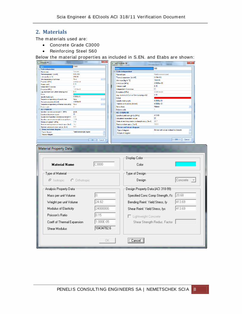
3. Loads
3.1. Gravity loads The loads applied were for simplicity the following: Self weight calculated automatically by the software Additional dead weight : 1.5 kN/m2 Live load: 5 kN/m2 Balconies 2 kN/m2 inner slabs and roof. The global force balance for the total of dead weight (self + G), live loads (L) and the mass combination G+0.3Q is shown in the following table for the Etabs and S.EN. models. The comparison shows differences less than 2%. ETABS Global Reactions S.EN. Global Reactions Diff GSW 5705.9 DEAD 6865.53 DEAD 1296.75 2.00% LIVE 2307.94 LIVE 2335.24 1.18% G+0.3Q 7557.912 G+0.3Q 7703.222 1.92%
3.2. Seismic loads The following spectra has been derived from ASCE SEI 7-10 using the following parameters:
PENELIS CONSULTING ENGINEERS SA | NEMETSCHEK SCIA 10
This spectra corresponds to the San Francisco bay area (Ch22, fig 22.2):
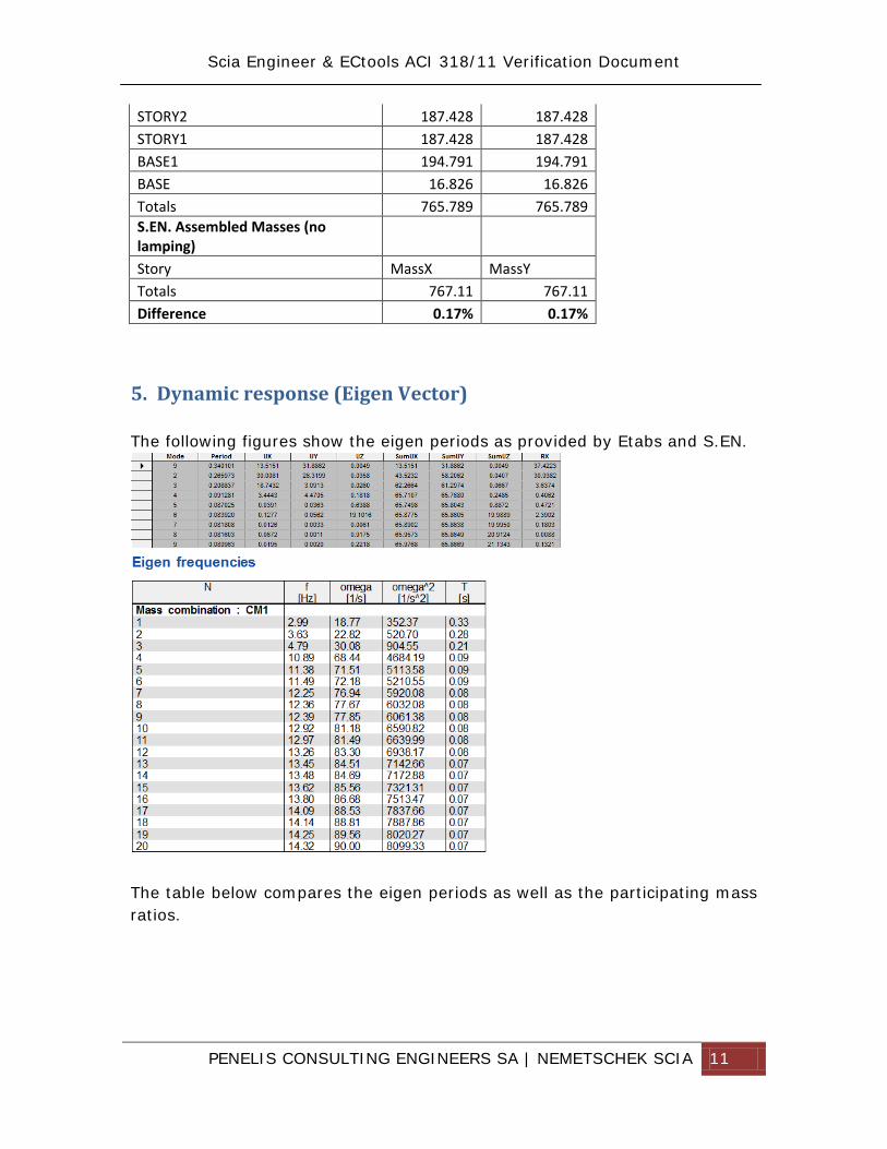
4. Mass The mass of the building has been defined for the quasi permanent combination G+0.30 Q, and is being calculated automatically both by Etabs and S.EN. The mass is calculated by dividing the loads by g. The table below includes the comparison which shows a difference less than 0.5%. ETABS Assembled Masses (no lamping) Storey MassX MassY STORY3 179.315 179.315
PENELIS CONSULTING ENGINEERS SA | NEMETSCHEK SCIA 12
It is clear that for the first 3 important modes the differences of S.EN. to
Etabs are around 3%. Considering the several different modelling approaches
used in the two software (i.e. lamped masses in Etabs Vs distributed masses
in S.EN., T beams as sections in Etabs Vs T beams as Ribs under Shells in
S.EN.) this coincidence is considered a match.
It is noted that for the insignificant modes (less than 4% active mass) the match is less accurate as one would expect between different software (hence the gray in the difference column). The table below shows the eigen deformations for each of the first three modes of vibration, using Etabs and S.EN. (3D view from top –z) Mode, T Etabs S.EN. 1, T=0.34/0.335
PENELIS CONSULTING ENGINEERS SA | NEMETSCHEK SCIA 13
6. Analysis results
6.1. General The following paragraphs compare internal forces on beams, columns and walls modeled in Etabs and S.EN. Considering the different modeling and F.E. approaches of the two software, the match is more than adequate. As a reference the following elements have been selected:
- D16 beam of storey 3 - K12 column of storey 3 - K5 column at basement - W1 wall at ground floor
6.2. Beams
6.2.1. Beams modeling general As it is known beams are modelled in S.EN. using a combined approach of 1D elements for the rib of a T-beam section and the slab F.E. for the flange. The resultant internal forces are a combination of the internal forces of the rib and the integrated stresses of the slab effective width.
PENELIS CONSULTING ENGINEERS SA | NEMETSCHEK SCIA 14
The weight and stiffners modifiers for the Etabs model are calculated in the following table:
Etabs does not have the save functionality, so beams are modelled as T sections with a weight modification factor so that the self-weight of flange is not calculated twice (once from the T beam section and once for the slab F.E.). Due to the fact that Etabs uses shell elements duplicated by the T-beam section, the correct moment and shear forces of the beam may only be calculated by adding to the beam forces the integrated sheel element corresponding forces. This is not very critical for the moment, while it is significant for the shear force. In the following paragraphs this procedure has indeed been manually applied for the shear forces of the beams.
6.2.1. Beams Dead load (G) The following table compares the results of beam internal forces for the dead load case, which in both software includes the self weight (In S.EN. the Dead is a combination of G+GSW)
T25x50x15 Actual Etabs slabLf 1 1tf 0.15 0.15h 0.5b 0.25A 0.2375 0.15Weight Mod 0.37 1A 0.2379J 4.628E-03 2.81E-04Stiff Mod 0.94 1J tot 4.632E-03
PENELIS CONSULTING ENGINEERS SA | NEMETSCHEK SCIA 17
6.3. Columns
6.3.1. Column modeling in general Columns are modelled in both software using 1D linear elements, therefore as the load transfer has been verified from the slabs and beams, the results are in agreement.
6.3.1. Dead load (G) The following table compares the results of column internal forces for the dead load case. K12 S3
PENELIS CONSULTING ENGINEERS SA | NEMETSCHEK SCIA 21
6.4. Walls
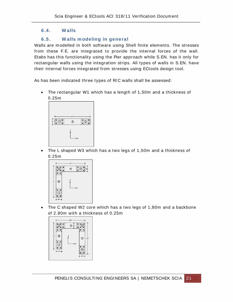
6.5. Walls modeling in general Walls are modelled in both software using Shell finite elements. The stresses from these F.E. are integrated to provide the internal forces of the wall. Etabs has this functionality using the Pier approach while S.EN. has it only for rectangular walls using the integration strips. All types of walls in S.EN. have their internal forces integrated from stresses using ECtools design tool. As has been indicated three types of R/C walls shall be assessed:
• The rectangular W1 which has a length of 1,50m and a thickness of 0.25m
• The L shaped W3 which has a two legs of 1,50m and a thickness of
0.25m
• The C shaped W2 core which has a two legs of 1,80m and a backbone
PENELIS CONSULTING ENGINEERS SA | NEMETSCHEK SCIA 22
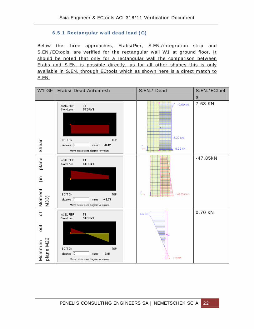
6.5.1. Rectangular wall dead load (G) Below the three approaches, Etabs/Pier, S.EN./integration strip and S.EN./ECtools, are verified for the rectangular wall W1 at ground floor. It should be noted that only for a rectangular wall the comparison between Etabs and S.EN. is possible directly, as for all other shapes this is only available in S.EN. through ECtools which as shown here is a direct match to S.EN. W1 GF Etabs/ Dead Automesh S.EN./ Dead S.EN./ECtool
PENELIS CONSULTING ENGINEERS SA | NEMETSCHEK SCIA 23
Axi
al
-356.08KN
ECtools calculation is shown below (as exported by ECtools in Scia Translation.xls exported in the temporary S.EN. folder after ECtools is executed)
6.5.1. Rectangular wall live load (L) Below the three approaches, Etabs/Pier, S.EN./integration strip and S.EN./ECtools, are verified for the rectangular wall W1 at ground floor. It should be noted that only for a rectangular wall the comparison between Etabs and S.EN. is possible directly, as for all other shapes this is only available in S.EN. through ECtools which as shown here is a direct match to S.EN. W1 GF Etabs/ Live S.EN./ Live S.EN./ECtool
PENELIS CONSULTING ENGINEERS SA | NEMETSCHEK SCIA 24
Mom
ent
(in
plan
e M
33)
-27.08 kN Axi
al
-195.94KN
ECtools calculation is shown below (as exported by ECtools in Scia Translation.xls exported in the temporary S.EN. folder after ECtools is executed)
The differences observed between S.EN. and Etabs are attributed to the Etabs automesh option, which when deactivated, as will be shown in the subsequent cases where the effect is more signifficant, the results for walls between S.EN. and Etabs&ECtools match.
6.5.2. L shaped wall dead load case (G) Below the two approaches, Etabs/Pier and S.EN./ECtools, are verified for the L Shaped wall W3 at ground floor.
PENELIS CONSULTING ENGINEERS SA | NEMETSCHEK SCIA 26
ECtools calculation is shown below (as exported by ECtools in Scia Translation.xls exported in the temporary S.EN. folder after ECtools is executed)
The axial and M33 moment are also calculated by using the integration strips of each leg of the L wall for the centroid, below.
This calculation, which is indirect shows a match between ECtools and S.EN., therefore the difference in the results of S.EN.&ECtools to Etabs are attributed to the analytical modeling itself. To further investigate the issue, the ETabs model is manually refined to a more dense mesh, thus rendering the automesh option useless. Below these results for the basic internal forces M33, N, V33 are shown:
PENELIS CONSULTING ENGINEERS SA | NEMETSCHEK SCIA 27
W3 GF Etabs/ Dead Automesh option
Etabs/ Dead Refined No Automesh
S.EN./ECtools
She
ar V
22
-7.06 M
omen
t (i
n pl
ane
M33
)
-39.65
Axi
al
-467.7kN
From the above it is clear that the automesh option in Etabs produces erroneous results in the case of R/C cores, and should be avoided. When this parameter is eliminated the differences between Etabs and S.EN. & ECtools are less than 10%.
6.5.1. L shaped wall live load case (L) Below the two approaches, Etabs/Pier and S.EN./ECtools, are verified for the L Shaped wall W3 at ground floor.
PENELIS CONSULTING ENGINEERS SA | NEMETSCHEK SCIA 29
ECtools calculation is shown below (as exported by ECtools in Scia Translation.xls exported in the temporary S.EN. folder after ECtools is executed)
The axial and M33 moment are also calculated by using the integration strips of each leg of the L wall for the centroid, below.
This calculation, which is indirect, shows a match between ECtools and S.EN., therefore the difference in the results of S.EN.&ECtools to Etabs are attributed to the analytical modeling itself. As in the case for the Dead loadcase, to further investigate the issue, the Etabs model is manually refined to a more dense mesh, thus rendering the automesh option useless. Below these results for the basic internal forces M33, N, V33 are shown:
PENELIS CONSULTING ENGINEERS SA | NEMETSCHEK SCIA 30
W3 GF Etabs/ Live Automesh
option Etabs/ Live Refined No Automesh
S.EN./ECtools
She
ar V
22
0.21
Mom
ent
(in
plan
e M
33)
-9.858
Axi
al
-218.58
From the above it is clear that the automesh option in Etabs produces erroneous results in the case of R/C cores, and should be avoided. When this parameter is eliminated, the differences between Etabs and S.EN. & ECtools are less than 10%.
PENELIS CONSULTING ENGINEERS SA | NEMETSCHEK SCIA 31
6.5.2. C shaped wall dead load case (G) Below the two approaches, Etabs/Pier and S.EN./ECtools, are verified for the C Shaped wall W2 at ground floor. W2 GF Etabs/ Dead Automesh option S.EN./ECtool
PENELIS CONSULTING ENGINEERS SA | NEMETSCHEK SCIA 32
ECtools calculation is shown below (as exported by ECtools in Scia Translation.xls exported in the temporary S.EN. folder after ECtools is executed)
The axial and M33 moment are also calculated by using the integration strips of each leg of the L wall for the centroid, below.
This calculation, which is indirect, shows a match between ECtools and S.EN., therefore the difference in the results of S.EN.&ECtools to Etabs are attributed to the analytical modeling itself. As in the case for the L shaped wall, to further investigate the issue, the Etabs model is manually refined to a more dense mesh, thus rendering the automesh option useless. Below these results for the basic internal forces M33, N, V33 are shown:
PENELIS CONSULTING ENGINEERS SA | NEMETSCHEK SCIA 33
W2 GF Etabs/ Dead Automesh option
Etabs/ Dead Refined No Automesh
S.EN./ECtools
She
ar V
22
28.106 M
omen
t (i
n pl
ane
M33
)
-278.62
Axi
al
-775.25
From the above it is clear that the automesh option in Etabs produces erroneous results in the case of R/C cores, and should be avoided. When this parameter is eliminated, the differences between Etabs and S.EN. & ECtools are less than 10%.
PENELIS CONSULTING ENGINEERS SA | NEMETSCHEK SCIA 34
6.5.1. C shaped wall live load case (L) Below the two approaches, Etabs/Pier and S.EN./ECtools, are verified for the C Shaped wall W2 at ground floor. W2 GF Etabs/ Live Automesh option S.EN./ECtool
PENELIS CONSULTING ENGINEERS SA | NEMETSCHEK SCIA 35
ECtools calculation is shown below (as exported by ECtools in Scia Translation.xls exported in the temporary S.EN. folder after ECtools is executed)
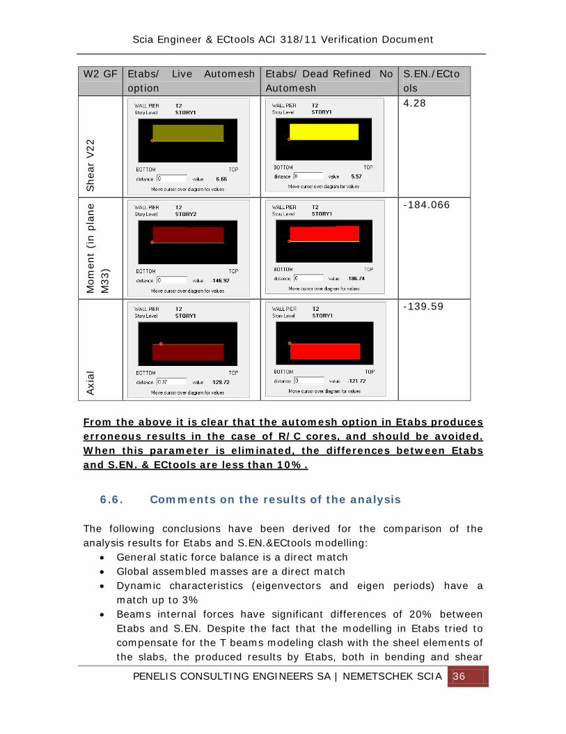
As in the case for the L shaped wall, to further investigate the issue, the Etabs model is manually refined to a more dense mesh, thus rendering the automesh option useless. Below these results for the basic internal forces M33, N, V33 are shown:
PENELIS CONSULTING ENGINEERS SA | NEMETSCHEK SCIA 36
W2 GF Etabs/ Live Automesh option
Etabs/ Dead Refined No Automesh
S.EN./ECtools
She
ar V
22
4.28 M
omen
t (i
n pl
ane
M33
)
-184.066
Axi
al
-139.59
From the above it is clear that the automesh option in Etabs produces erroneous results in the case of R/C cores, and should be avoided. When this parameter is eliminated, the differences between Etabs and S.EN. & ECtools are less than 10%.
6.6. Comments on the results of the analysis The following conclusions have been derived for the comparison of the analysis results for Etabs and S.EN.&ECtools modelling:
• General static force balance is a direct match • Global assembled masses are a direct match • Dynamic characteristics (eigenvectors and eigen periods) have a
match up to 3% • Beams internal forces have significant differences of 20% between
Etabs and S.EN. Despite the fact that the modelling in Etabs tried to compensate for the T beams modeling clash with the sheel elements of the slabs, the produced results by Etabs, both in bending and shear
PENELIS CONSULTING ENGINEERS SA | NEMETSCHEK SCIA 37
behavior underestimate the actual forces as part of the Moment and shear is transferred to the shell elements of the slab that coincide with the flange of the T beams. This effect is more serious in shear than in moment behavior, and does not take place in S.EN. where the internal forces of T beams are calculated as an integration of the 1D rib internal forces with the effective flange of the slab shell elements. It has been proven, in the relevant paragraph that the S.EN. approach is the accurate solution.
• Column internal forces are a direct match between the two software with less than 5% difference.
• Wall internal forces, either for rectangular walls or RC cores, although the modelling is different, produce results with less than 5% differences. It should be noted that again Etabs, when in automesh option, produces underestimated values for cores, a fact that has been demonstrated by comparing an automesh model to a manualy refined mesh model. S.EN. is not affected by the automatic meshing.
PENELIS CONSULTING ENGINEERS SA | NEMETSCHEK SCIA 38
7. Design results
7.1. Beams Flexure ordinary frame
7.1.1. General results Below the results for beam D16 at storey 3 are presented using the following design parameters for ECtools (left) and Etabs (right):
For both cases Ductility Class/ Framing type has been set to ordinary:
PENELIS CONSULTING ENGINEERS SA | NEMETSCHEK SCIA 39
7.1.2. Calculated reinforcement The following table shows the Etabs ACI318-11 design output for the beam D16 (envelope results):
The following table shows the ECtools design output.
From the Etabs output the following values seem out of place: Top Left Moment = -29.18 kNm for DCon26 is not the correct value as is clear from the Etabs flexural detailed design that has the same Moment, for the same Combination as -50.41 kNm. Bottom Left Moment = 19.87 kN, does not result from the design combination DCon26. To confirm these observations, the results from the flexural design of Beam left are shown, from Etabs, as following:
PENELIS CONSULTING ENGINEERS SA | NEMETSCHEK SCIA 40
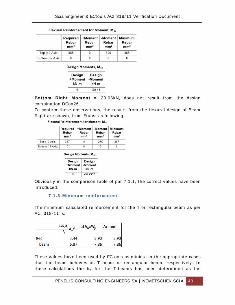
Bottom Right Moment = 23.96kN, does not result from the design combination DCon26. To confirm these observations, the results from the flexural design of Beam Right are shown, from Etabs, as following:
Obviously in the comparison table of par 7.1.1, the correct values have been introduced.
7.1.3. Minimum reinforcement The minimum calculated reinforcement for the T or rectangular beam as per ACI 318-11 is:
These values have been used by ECtools as minima in the appropriate cases that the beam behaves as T beam or rectangular beam, respectively. In these calculations the bw for the T-beams has been determined as the
PENELIS CONSULTING ENGINEERS SA | NEMETSCHEK SCIA 41
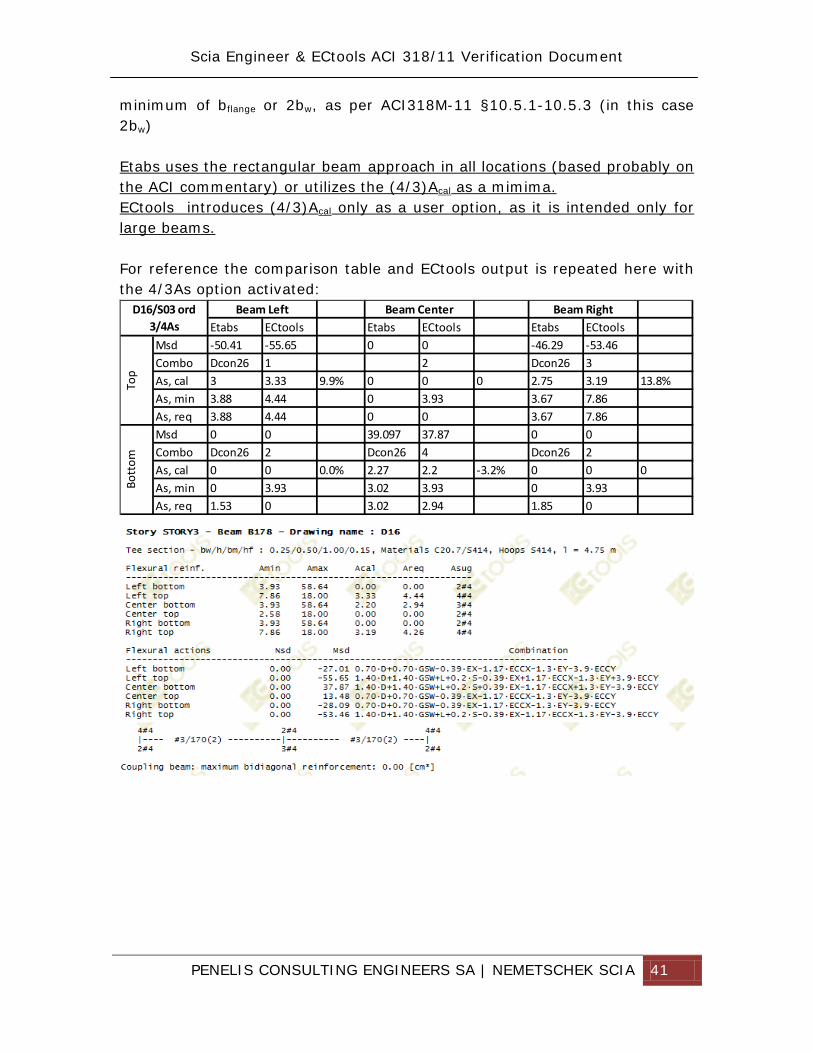
minimum of bflange or 2bw, as per ACI318M-11 §10.5.1-10.5.3 (in this case 2bw) Etabs uses the rectangular beam approach in all locations (based probably on the ACI commentary) or utilizes the (4/3)Acal as a mimima. ECtools introduces (4/3)Acal only as a user option, as it is intended only for large beams. For reference the comparison table and ECtools output is repeated here with the 4/3As option activated:
PENELIS CONSULTING ENGINEERS SA | NEMETSCHEK SCIA 42
7.2. Beams Shear ordinary
7.2.1. General results Below the results for beam D16 at storey 3 are presented using the following design parameters for ECtools (left) and Etabs (right):
For both cases Ductility Class/ Framing type has been set to ordinary:
PENELIS CONSULTING ENGINEERS SA | NEMETSCHEK SCIA 43
7.2.2. Calculated reinforcement The following table shows the Etabs ACI318-11 envelope design output for the beam D16 (envelope results):
The output of ECtools shear design is shown in the following figure:
The Etabs shear force values pointed out in red in the summary table, do not correspond to the shear design as elaborated within Etabs, and the calculated shear reinforcement does not result from these values. The design for combination Dcon 26 for the left of the beam is shown below:
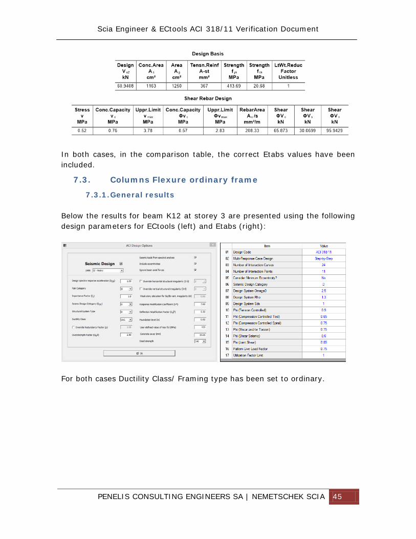
PENELIS CONSULTING ENGINEERS SA | NEMETSCHEK SCIA 45
In both cases, in the comparison table, the correct Etabs values have been included.
7.3. Columns Flexure ordinary frame
7.3.1. General results Below the results for beam K12 at storey 3 are presented using the following design parameters for ECtools (left) and Etabs (right):
For both cases Ductility Class/ Framing type has been set to ordinary.
PENELIS CONSULTING ENGINEERS SA | NEMETSCHEK SCIA 46
7.3.2. Calculated reinforcement The suggested reinforcement in both software is 12.25cm², which results from the minimum allowable reinforcement. The results plotted by Etabs are shown in the following figure:
The results plotted by ECtools are shown in the following figure:
PENELIS CONSULTING ENGINEERS SA | NEMETSCHEK SCIA 47
It should be noted that Etabs inverts the sign of the axial force for design purposes (+ means compression) as noted in the following graph:
From the same graph the utilization factor for the bottom of Dcon32 is 0.401, therefore the calculated As,cal = 4.9cm² (12.25x0.401) while for the top is 3.76cm² (12.25x0.307).
7.4. Columns Flexure special frame
7.4.1. General results Below the results for beam K12 at storey 3 are presented using the following design parameters for ECtools (left) and Etabs (right):
For both cases Ductility Class/ Framing type has been set to special.
PENELIS CONSULTING ENGINEERS SA | NEMETSCHEK SCIA 48
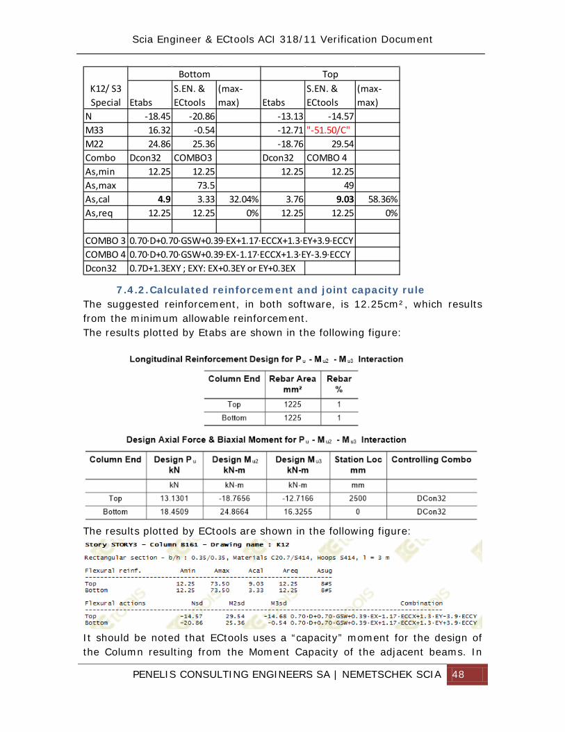
7.4.2. Calculated reinforcement and joint capacity rule The suggested reinforcement, in both software, is 12.25cm², which results from the minimum allowable reinforcement. The results plotted by Etabs are shown in the following figure:
The results plotted by ECtools are shown in the following figure:
It should be noted that ECtools uses a “capacity” moment for the design of the Column resulting from the Moment Capacity of the adjacent beams. In
PENELIS CONSULTING ENGINEERS SA | NEMETSCHEK SCIA 49
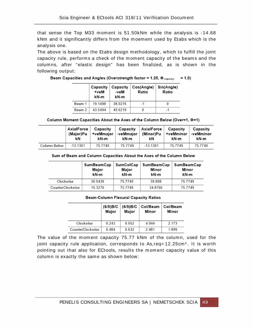
that sense the Top M33 moment is 51.50kNm while the analysis is -14.68 kNm and it significantly differs from the moement used by Etabs which is the analysis one. The above is based on the Etabs design methodology, which to fulfill the joint capacity rule, performs a check of the moment capacity of the beams and the columns, after “elastic design” has been finalized, as is shown in the following output:
The value of the moment capacity 75.77 kNm of the column, used for the joint capacity rule application, corresponds to As,req=12.25cm². It is worth pointing out that also for ECtools, results the moment capacity value of this column is exactly the same as shown below:
PENELIS CONSULTING ENGINEERS SA | NEMETSCHEK SCIA 50
Therefore the joint capacity rule has been applied in both software, via a different path, resulting in the same values.
7.5. Columns Shear ordinary
7.5.1. General results Below the results for column K12 at storey 3 are presented using the following design parameters for ECtools (left) and Etabs (right):
For both cases Ductility Class/ Framing type has been set to ordinary.
PENELIS CONSULTING ENGINEERS SA | NEMETSCHEK SCIA 51
7.5.2. Shear reinforcement The analytical calculation as is plotted from Etabs for the Top & Bottom of column. Bottom of column detailed calculation is shown below:
PENELIS CONSULTING ENGINEERS SA | NEMETSCHEK SCIA 52
Top of column detailed calculation is shown below:
The analytical calculation as is plotted from ECTools for the Top & Bottom of column, is shown below:
In both software the capacity of the concrete is more than the required reinforcement. ECtools provides also the minimum required shear reinforcement, while Etabs does not (includes it in detailing options)
PENELIS CONSULTING ENGINEERS SA | NEMETSCHEK SCIA 53
7.6. Columns Shear Special
7.6.1. General results Below the results for beam K12 at storey 3 are presented using the following design parameters for ECtools (left) and Etabs (right):
For both cases Ductility Class/ Framing type has been set to special.
PENELIS CONSULTING ENGINEERS SA | NEMETSCHEK SCIA 54
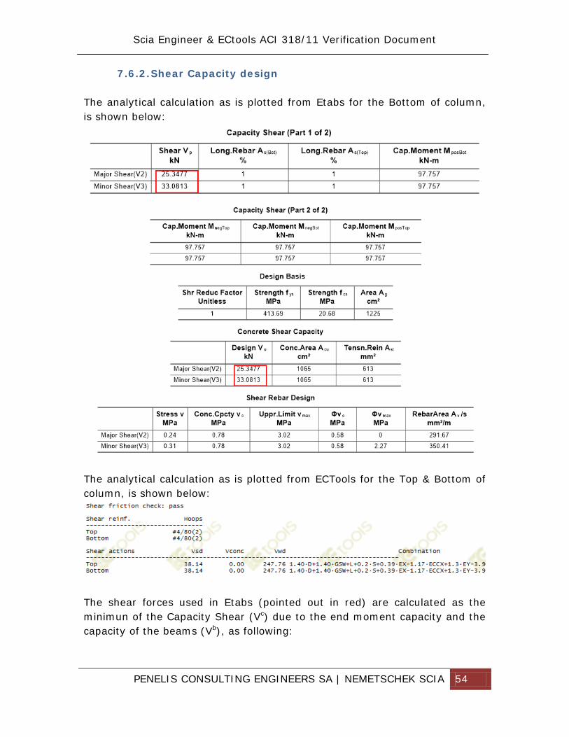
7.6.2. Shear Capacity design The analytical calculation as is plotted from Etabs for the Bottom of column, is shown below:
The analytical calculation as is plotted from ECTools for the Top & Bottom of column, is shown below:
The shear forces used in Etabs (pointed out in red) are calculated as the minimun of the Capacity Shear (Vc) due to the end moment capacity and the capacity of the beams (Vb), as following:
PENELIS CONSULTING ENGINEERS SA | NEMETSCHEK SCIA 55
(a) Vc Capacity shear due to moments
Which applied in this case results in a capacity shear of: Vc= 2x97.75/3 = 65.1 KN instead of Vb= 33 kN.
(b) Capacity Shear due to capacity of framing beams, i.e.
Which applied in this case results in a capacity shear of: Vb=33 kN The resulting shear reinforcement 350 mm2/m for Etabs corresponds to a shear force capacity of the rebars Vwd:
Vwd=350x10-6x0.75x414x103x0.335 = 36.4 kN, which corresponds to the shear force used ignoring the concrete contribution to the shear capacity.
PENELIS CONSULTING ENGINEERS SA | NEMETSCHEK SCIA 56
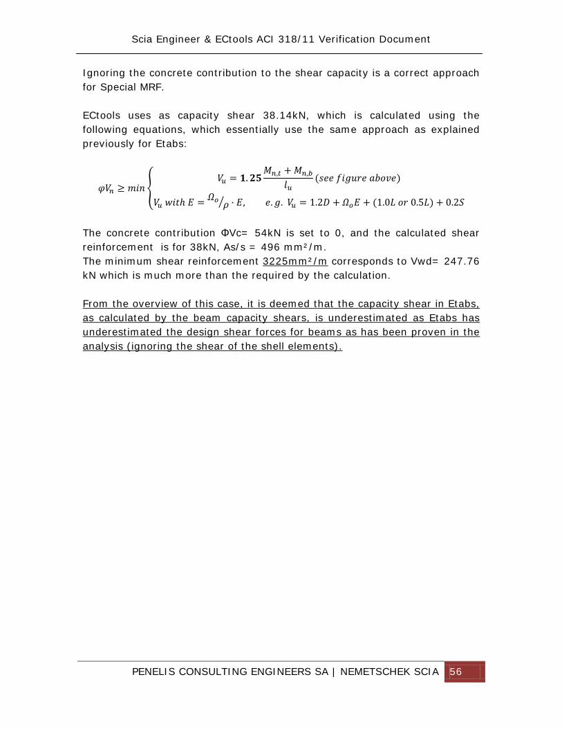
Ignoring the concrete contribution to the shear capacity is a correct approach for Special MRF. ECtools uses as capacity shear 38.14kN, which is calculated using the following equations, which essentially use the same approach as explained previously for Etabs:
The concrete contribution ΦVc= 54kN is set to 0, and the calculated shear reinforcement is for 38kN, As/s = 496 mm²/m. The minimum shear reinforcement 3225mm²/m corresponds to Vwd= 247.76 kN which is much more than the required by the calculation. From the overview of this case, it is deemed that the capacity shear in Etabs, as calculated by the beam capacity shears, is underestimated as Etabs has underestimated the design shear forces for beams as has been proven in the analysis (ignoring the shear of the shell elements).
PENELIS CONSULTING ENGINEERS SA | NEMETSCHEK SCIA 57
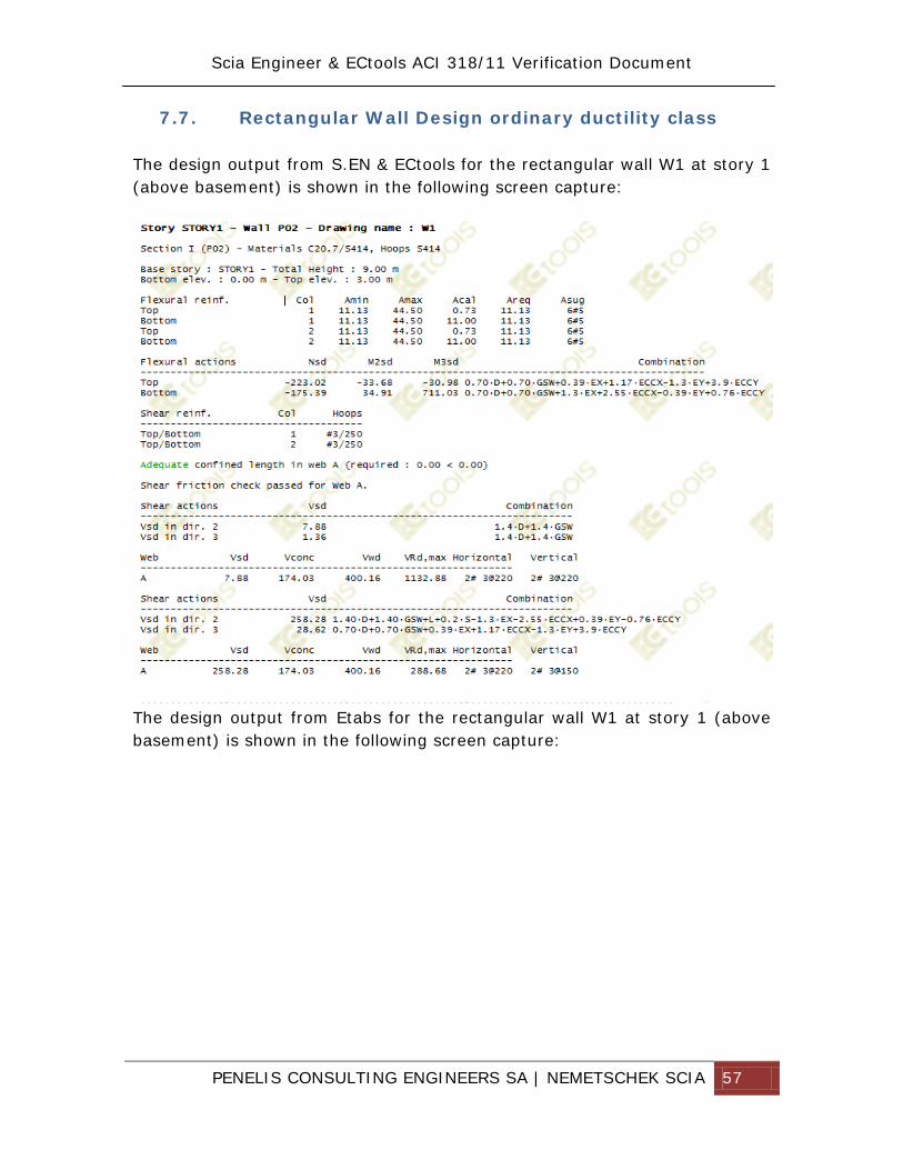
7.7. Rectangular Wall Design ordinary ductility class The design output from S.EN & ECtools for the rectangular wall W1 at story 1 (above basement) is shown in the following screen capture:
The design output from Etabs for the rectangular wall W1 at story 1 (above basement) is shown in the following screen capture:
PENELIS CONSULTING ENGINEERS SA | NEMETSCHEK SCIA 58
ECtools calculates for the bottom of the wall (base of wall) flexural reinforcement of As, req= 11.13+11.13 = 22.26 cm2 while Etabs calculates As,req= 24.49cm2, i.e. a difference of 5% ECtools calculates for the bottom of the wall (base of wall) shear reinforcement 2x3#/280 As/s=5.07 cm2/m while Etabs calculates As/s = 6.25 cm2/m, i.e. 18% difference.
PENELIS CONSULTING ENGINEERS SA | NEMETSCHEK SCIA 59
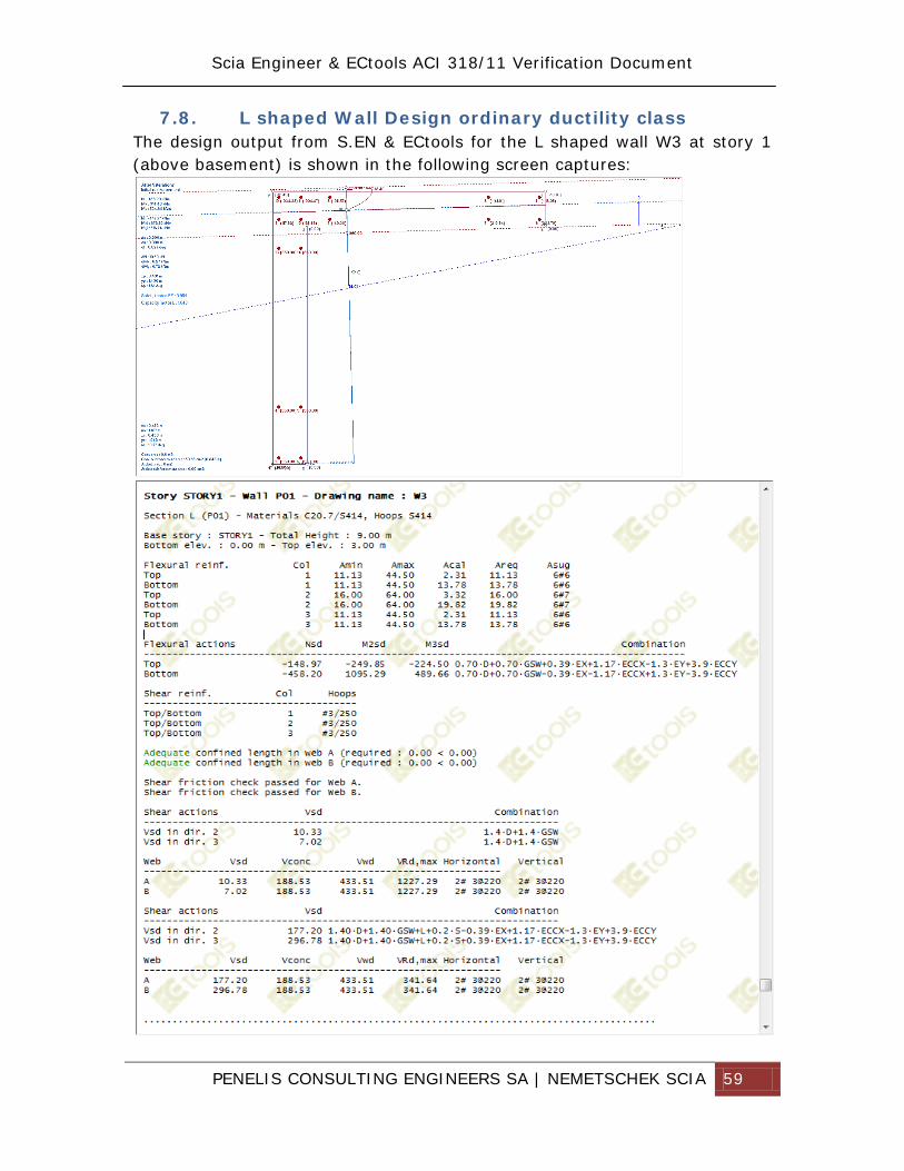
7.8. L shaped Wall Design ordinary ductility class The design output from S.EN & ECtools for the L shaped wall W3 at story 1 (above basement) is shown in the following screen captures:
PENELIS CONSULTING ENGINEERS SA | NEMETSCHEK SCIA 60
The design output from Etabs for the L shaped wall W3 at story 1 (above basement) is shown in the following screen capture:
ECtools calculates for the bottom of the wall (base of wall) flexural reinforcement of As, req= 13.78+19.82+13.78= 47.38 cm2 while Etabs calculates As,req= 78.7cm2. If the N-M2-M3 of Etabs are used as input for ECtools, the resulting reinforcement is A=67.5ocm², i.e. 14% difference.
ECtools calculates for the bottom of the wall (base of wall) shear reinforcement per leg 2x3#/280 As/s=5.07 cm2/m while Etabs calculates As/s = 6.25 cm2/m, i.e. 18% difference per leg.
PENELIS CONSULTING ENGINEERS SA | NEMETSCHEK SCIA 61
7.1. C shaped Wall Design ordinary ductility class The design output from S.EN & ECtools for the C shaped wall W2 at story 1 (above basement) is shown in the following screen captures:
PENELIS CONSULTING ENGINEERS SA | NEMETSCHEK SCIA 62
The design output from Etabs for the C shaped wall W2 at story 1 (above basement) is shown in the following screen capture:
The forces used in the design, resulting from DWall32 combination, correspond to the forces from the analysis, which are shown for verification as screen captures below:
PENELIS CONSULTING ENGINEERS SA | NEMETSCHEK SCIA 63
ECtools calculates for the bottom of the wall (base of wall) flexural reinforcement of As, req= 12.12+18.76+18.76+12.22 = 61.76 cm2, while Etabs calculates As,req= 78.15cm2, i.e a difference of 19%. ECtools calculates for the bottom of the wall (base of wall) shear reinforcement per leg 2x3#/280 As/s=5.07 cm2/m while Etabs calculates As/s = 6.25 cm2/m, i.e. 18% difference per leg.
PENELIS CONSULTING ENGINEERS SA | NEMETSCHEK SCIA 64
Example 2: Athens Opera House (SNFCC)
1. Introduction
The purpose of this report is to present the results of the design verification of the Opera House superstructure. The superstructure was modelled both in Etabs and Scia Engineer, by two teams working in parallel, so that human error or software bugs could be eliminated. This was decided due to the complexity and irregularity of the building.
As it can be easily seen from the numerical models, a large canopy on top of the Opera (100mx100m) has been accurately modelled both regarding geometry and loads, so that its effects are included in the opera static and dynamic response.
2. General Approach
An effort was made to reduce the number of factors that could produce discrepancies between the models. To that end:
• All loads, spectra, loading assumptions and load combinations were taken exactly the same
Please refer to appendix “Codes, Loads and Materials” for a detailed analysis of the loads, the design combinations and the codes applied.
• Extra loads pertaining to the stage pit and the flytower were
calculated from the relevant stage engineering technical descriptions.
• The comparison of foundation loads between was made using models without vertical springs (rigid foundation) since the addition of the deformability of the substructure would only increase the variability of the data.
Two separate numerical software were used to model the Opera House with the solar collector on top, ETABS v9.7.4 (CSI) and SCIA Engineer 2012 (Nemetschek). This double numerical modelling approach was deemed necessary given the complexity of the project, so that subsequent errors and
PENELIS CONSULTING ENGINEERS SA | NEMETSCHEK SCIA 65
discrepancies in the modelling of the geometry, in the application of loads etc. would be exposed and corrected. The solar canopy was modelled both on top the main building.
3. Numerical Models
Two numerical models were created for the Opera House, one in SCIA and one in Etabs.
• In both software, the main structure was modelled with the solar collector on top.
• Columns were modelled using frame elements.
• T-beams were modelled using frame elements for the webs. These were assigned a vertical stiffness offset from the T section’s flange, creating the actual beam stiffness. SCIA integrates the forces from the web and the flange automatically, producing the resulting T-section forces.
• Walls and spandrels were modelled using shell elements.
• Slabs were modelled using shell elements. Voided slabs were also modelled using shell elements with equivalent stiffnesses. Ribbed and waffle slabs were modelled using shell elements for the flanges and frames for the ribs. The rib frames were assigned a vertical stiffness offset in order to reproduce the actual slab section’s stiffness.
• The solar collector’s ribs were modelled via a stiffness modifier to the relevant flanges. The solar collector’s beams were modelled using frame elements that were assigned a vertical stiffness offset.
• Surface loads were applied to slabs, line loads were applied to either existing beams or supplementary zero-weight and zero-stiffness linear elements connected to the slabs’ mesh.
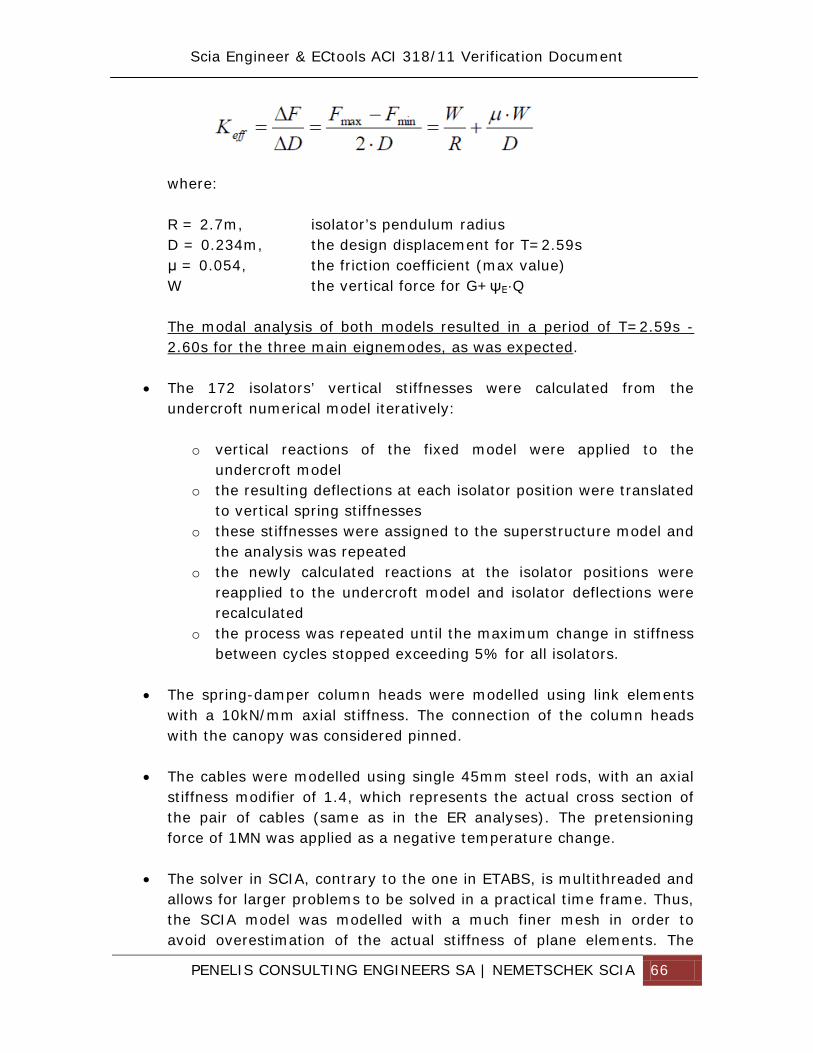
• The 172 isolators’ horizontal stiffnesses were calculated using the following expression:
PENELIS CONSULTING ENGINEERS SA | NEMETSCHEK SCIA 66
where: R = 2.7m, isolator’s pendulum radius D = 0.234m, the design displacement for T=2.59s μ = 0.054, the friction coefficient (max value) W the vertical force for G+ψΕ·Q
The modal analysis of both models resulted in a period of T=2.59s - 2.60s for the three main eignemodes, as was expected.
• The 172 isolators’ vertical stiffnesses were calculated from the
undercroft numerical model iteratively:
o vertical reactions of the fixed model were applied to the undercroft model
o the resulting deflections at each isolator position were translated to vertical spring stiffnesses
o these stiffnesses were assigned to the superstructure model and the analysis was repeated
o the newly calculated reactions at the isolator positions were reapplied to the undercroft model and isolator deflections were recalculated
o the process was repeated until the maximum change in stiffness between cycles stopped exceeding 5% for all isolators.
• The spring-damper column heads were modelled using link elements
with a 10kN/mm axial stiffness. The connection of the column heads with the canopy was considered pinned.
• The cables were modelled using single 45mm steel rods, with an axial stiffness modifier of 1.4, which represents the actual cross section of the pair of cables (same as in the ER analyses). The pretensioning force of 1MN was applied as a negative temperature change.
• The solver in SCIA, contrary to the one in ETABS, is multithreaded and allows for larger problems to be solved in a practical time frame. Thus, the SCIA model was modelled with a much finer mesh in order to avoid overestimation of the actual stiffness of plane elements. The
PENELIS CONSULTING ENGINEERS SA | NEMETSCHEK SCIA 67
SCIA model has 75.000 shell elements, while the ETABS model has 28.000 shell elements. Even though this leads in general to more accurate results from the SCIA model, the two models are in good agreement due to a significant effort that was made to optimize the meshing of the walls in ETABS.
PENELIS CONSULTING ENGINEERS SA | NEMETSCHEK SCIA 71
4. Global Model Verification – Gravity Loads
4.1. Summation of loads at base The sum of forces for the combination 1.35G + 1.50Q for the twomodels are presented in the following table:
ETABS SCIA 1771693 kN 1772505 kN
The difference between models is less than 0.5‰, rendering them equal in the total load application. Since the total load has been calculated effectively the same, any individual differences that should arise will be the product of the load positioning and the modelling of the structure stiffnesses.
4.2. Comparison of reactions at individual isolator positions The comparison of reactions for individual isolators was done between the JVIT models for three (3) cases:
1. One with fixed supports and with stiffnesses for walls and beams reduced by 50%
2. One with fixed supports and full stiffnesses 3. One with spring supports (calculated from undercroft ETABS model
and SCIA superstructuremodel) and full stiffnesses The results are presented in the following table:
The following observations are made from the above comparisons:
1. Even though the sum total for gravity loads is exactly the same for the two models, their distribution in the structure displays some variance.
2. The variance is 4x greater for the models supported on fixities than the variance observed for the models supported on springs.
The root cause for this behavior is the coarser mesh of the ETABS model compared to the SCIA, which results in an erroneously “stiffer” model. Combined with rigid supports, the error is compounded. Combined with elastic supports which are significantly less stiff than the elements they support, the error is mitigated.
PENELIS CONSULTING ENGINEERS SA | NEMETSCHEK SCIA 77
8. Global Modelling Verification – Dynamic Analysis
The dynamic behavior of the superstructure is governed by the presence of the base isolators, their horizontal stiffnesses and their fundamental period. Their horizontal stiffness is directly proportional to the vertical force applied according to equation
In turn, the vertical force for each isolator is equal to the overlying mass times 9.81m/sec². Consequently:
• the center of stiffness of the group of isolators coincides with the center of mass of the structure
• the center of the polar mass moment of inertia of the superstructurearound the vertical axis coincides with the center of torsional stiffness of the group of isolators
• the ratios m/Kisol and Jm/Jisol are equal The net effect is that the fundamental period for each degree of freedom (2 translational, 1 rotational, 3 total) is the same and equal to T = 2.59s. Furthermore the structure should exhibit no rotation under horizontal excitation along any direction. These 3 eigenmodes were produced by both ETABS and SCIA JVIT models with periods between 2.56s and 2.59s. Combined they include 99.9% of the structure’s mass for each degree of freedom. The table below presents the results from ETABS.
The project design spectra were assigned on the two orthogonal directions X and Y. The result was a translational response along the direction of each excitation (X & Y) with virtually no rotation. Therefore the assignment of the horizontal springs was done correctly in both JVIT models.
PENELIS CONSULTING ENGINEERS SA | NEMETSCHEK SCIA 79
The calculated response spectrum displacements are:
Excitation Direction
AGORA ROOF UX UY UX UY
X-X 154 mm 3 mm 158 mm 5 mm
Y-Y 0 mm 154 mm 0 mm 158 mm Multiplied by q=1.50, they produce the elastic displacement, used for the base isolator design. D = 154·1.50 = 231mm This value is in agreement with both calculations concerning the base isolation design. Therefore the numerical dynamic analysis is correct.
PENELIS CONSULTING ENGINEERS SA | NEMETSCHEK SCIA 80
Conclusions
Two different approaches have been applied for the verification of Scia Engineer & ECtools using CSI Etabs as the reference software, for ACIA 318-11 reinforced concrete design.
- Approach of example 1, examines in depth all the modelling approaches and design options and results for a 3D R/C dual system with 3 storeys and one basement
- Approach of Athens Opera House, compares the two software on the application on one of the most demanding structural models and assessed global behavior analysis results.
From the detailed analysis examination of example 1, the following conclusions have been derived:
- Global force balance is identical for both software - Global assembled masses are identical for both software - The dynamic characteristics of the two models are identical with a
deviation of less than 4% - The modelling of beams in S.EN. (rib and integration flange approach)
is more accurate than Etabs, as the latter ignores the moment and shear forces of the slab shell elements clashing with T-beam flanges. This difference is not considered significant in the design of a building.
- The modeling of columns in both software is a close match. - The modelling of complex walls in S.EN. and Etabs are closer than
10%, when Etabs has a manual meshing of the finite elements of walls and slabs (in the automesh option, Etabs pier forces are not accurate)
From the design of R/C elements using S.EN. & ECtools or Etabs the following conclusions are derived:
- Beams design in Etabs does not take into account the minimum reinforcement requirements for T beams and uses as default the 4/3Acal rule allowed by the ACI 318-11. S.EN. & ECtools uses the actual minima as defined in the main text of ACI318-11 and has the 4/3Acal as a user option, as it is aimed only for large R/C beams (ACI commentary). The general design of beam, in both software, produces close match.
PENELIS CONSULTING ENGINEERS SA | NEMETSCHEK SCIA 81
- Column design in both software produces identical results in flexure and shear, both regarding ordinary and special ductility class. Also the minima in both software are the same.
- The joint capacity rule, although applied using a different path in the two software, produces the same results and safety factor.
- Wall design for the ordinary case is comparable in both cases, both in flexure and shear
From the second example, the Athens Opera House, it is concluded that S.EN. can be used in very complex buildings and produce results directly comparable to CSI Etabs. The general conclusion, derived from the development of this very elaborate report, is that an educated structural engineer, who is knowledgeable about any of the two software, may trust these without hesitation. It should however be noted, that both software are extremely advanced providing many user options, which are not to be used by newcomers or occasional users.