NEQ6 Belt Modification Kit. Thank you for your purchase. Please read these instructions fully before fitting. Your package should contain – 2 off 47 & 2 off 12 tooth aluminium pulleys 2 off belts 6mm wide x 2.5mm pitch x 180.0 long 1 off RA Motor / idler mounting assembly 1 off Dec Motor / idler mounting assembly 4 off M3x6 long, 3 off M4x12 long socket cap screws fitted with each mounting assembly. 4 off M5x12 long socket cap screws 3 off allen keys, 2.0, 2.5, 3.0mm Installation. The installation of the belt kit requires the mount to be disassembled which requires a degree of mechanical skill. Please seek local help if you are unsure of any of the techniques required. Additional tools are required to those supplied with the kit. . We recommend leaving the mount on its tripod and placing a clean and clear working table along side. Keep all bearings, worm wheels completely free from dirt, dust or contamination. 1. Remove 4 x screws from control panel. Taking anti-static precautions disconnect the motors and polar illumination leads from the circuit board on the reverse of the control panel.
2. Remove 2 socket cap screws from each motor plate. Withdraw the motors from the housing. Make a note of which motor is RA and which is Dec.
3. Loosen 3 x grub screws in the Dec end cap and unscrew the cap and counterweight shaft.
4. Remove 4 M6 socket cap screws from the Dec worm housing. Fully loosen both opposing worm mesh adjustment grub screws.
5. Withdraw the Dec axis shaft assembly from the main housing. Take care to hold on to the Dec taper thrust bearing. Place it in a plastic bag to keep it clean. It may be necessary to use a soft faced mallet to gently tap out the shaft. Note the position and number of any plastic shim washers. Place the Dec axis to one side.
6. Unscrew the polar scope and place to one side. Remove the 3 screws from the polar scope index ring/cover.
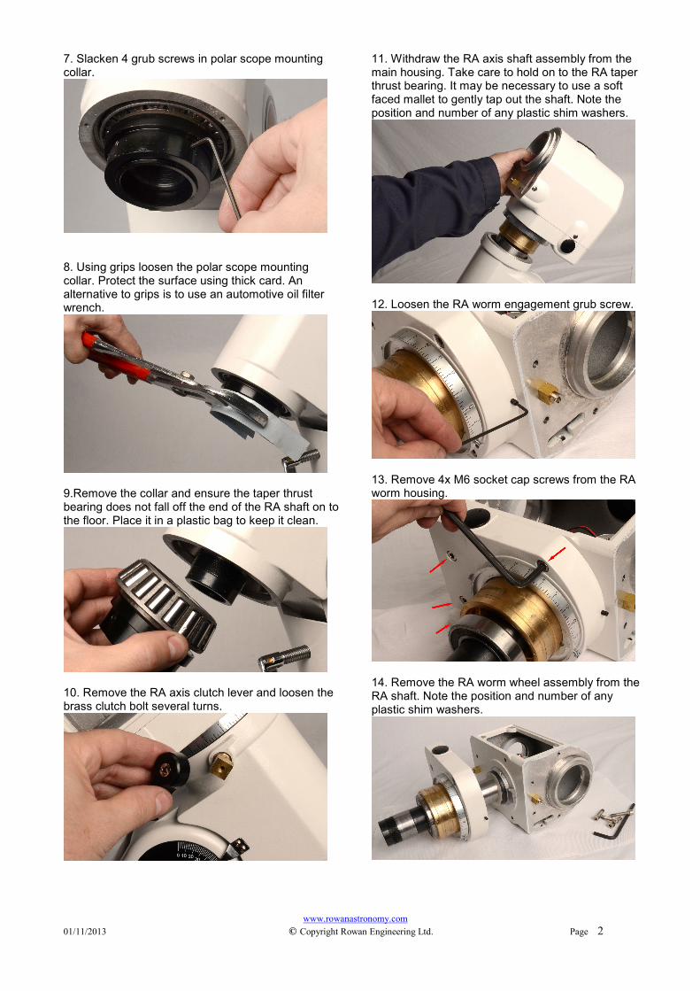
7. Slacken 4 grub screws in polar scope mounting collar.
8. Using grips loosen the polar scope mounting collar. Protect the surface using thick card. An alternative to grips is to use an automotive oil filter wrench.
9.Remove the collar and ensure the taper thrust bearing does not fall off the end of the RA shaft on to the floor. Place it in a plastic bag to keep it clean.
10. Remove the RA axis clutch lever and loosen the brass clutch bolt several turns.
11. Withdraw the RA axis shaft assembly from the main housing. Take care to hold on to the RA taper thrust bearing. It may be necessary to use a soft faced mallet to gently tap out the shaft. Note the position and number of any plastic shim washers.
12. Loosen the RA worm engagement grub screw.
13. Remove 4x M6 socket cap screws from the RA worm housing.
14. Remove the RA worm wheel assembly from the RA shaft. Note the position and number of any plastic shim washers.
15. Loosen the RA setting circle thumb screws and lift the worm housing from the wheel. Remove the RA worm bearing end covers using circlip pliers or snipe nosed pliers.
16. Loosen the 2 motor gear set screws using an allen key.
17. Using the optional bearing nut removal tool remove the slotted nut from the worm housing or alternatively use circlip pliers.
18. Pull the worm shaft from the side of the housing to leave the motor gear free. It may be necessary to remove the other worm bearing end cap and gently tap the end of the shaft to remove the gear.
19. Temporarily place the 47 tooth pulley on the worm shaft and check the shaft shoulder is above the pulley face by 1.0mm. Loop a belt around a 47 tooth pulley and slide the worm back into position. Gently tighten the 2 grub screws with longer grub screw against the shaft flat. Check the pulley does not rub on the casting. There must be a small gap between the pulley and side wall of the casting.
20. Replace the wheel in to the worm housing and replace the slotted nut. Lightly tighten the nut just enough to remove any axial play in the worm. Replace the bearing end cap.
21. Replace the RA worm wheel assembly on to the RA shaft, check that the shim washers are correct.
22. Carefully feed the belt through the slot in the casting while pushing the worm housing in to position.
23. Replace 4 x M6 socket head screws and leave just finger tight. Final worm-wheel mesh adjustment can be carried out last.
24. Replace the RA shaft assembly in to the lower housing.
25. Replace the RA taper thrust bearing and polar scope collar on to the RA shaft. Tighten the collar just sufficiently to remove any play in the RA shaft. Lock the 4 grub screws in the collar
26. Now working on the Dec axis assembly, remove the Dec axis clutch lever and loosen the brass clutch bolt several turns.
27. Remove the worm housing from the Dec shaft.
28. Separate the worm housing from the wheel.
29. Repeat steps 15 to 20 on the Dec worm to fit the 47 tooth pulley and belt.
30. Fit the Dec worm housing assembly on to the Dec shaft.
31. Carefully feed the belt through the slot in the casting while pushing the Dec shaft assembly in to position and replace 4 x M6 socket head screws and leave just finger tight. Final worm-wheel mesh adjustment can be carried out last.
32. Replace the Dec end cap and counterweight shaft. Tighten the cap just sufficiently to remove any play from the Dec axis. Tighten the 3 x grub screws.
33. The next steps can be carried out on both motors together. Remove the 3x M3 socket head screws.
34. Remove 2 M4 grub screws and extract the gear from the motor shaft. Using a small needle file clean the small dent in the shaft made by the grub screw.
35. Fit the 12 tooth pulley on to the motor. Temporarily place the motor on the plate assembly and check the motor pulley is positioned centrally to the idler rollers. Gently tighten the 2 grub screws with one against the shaft flat.
36. Separate the motor mounting and idler plates.
37. Fit the motor to the motor plate using 4 M3x8 socket head cap screws. Note the shape of the plates and the direction of the motor wires for RA and Dec
39. When fitting the socket head bolts the following tip may help. Use part of one of the plastic zip-lok bags and place over the end of the allen key to hold the bolt.
40. Slide the idler plate over the tweezers and guide the idler rollers over the loop in the belt. Fix in position using 2 M5x16 socket cap head bolts and leave finger tight. Take care not to drop any fasteners down the polar axis.
41. Place the motor so the pulley passes thorough the idler plate and on to the belt. Fit the 3 M4x12 socket cap bolts. Apply a light tension to the belt and at the same time gently turn the end of the worm shaft. This will rotate the belt so it engages with the teeth on the pulley. Finally tighten all M5 and M4 socket head bolts.
42. Connect the motors and polar illumination led to their respective sockets on the control board.
43. Fit the control panel in position checking that the cables are routed so as not to touch any moving parts. 44. Worm-wheel mesh adjustment. The 4 M6 socket head bolts left finger tight from earlier steps should be loose enough to allow the worm housing to move when the worm-wheel adjustment screws are turned. The photo below shows the Dec screw that tightens the worm wheel mesh. The opposing screw on the opposite side of the housings releases the mesh. Before tightening one screw, always loosen the opposite screw. With the axis clutch locked take hold of the axis and ‘feel’ for play in the worm wheel mesh. When approaching to the correct setting, make very small adjustments of 1/8 turn or less. Tighten the 4 M6 socket head screws and run the motor on the axis you are adjusting. Finally run the mount a full 360' to make sure there is no binding at any point. If binding occurs you will need to readjust the grub screws. Take your time to get the best setting. Repeat for the RA axis.
Your belt conversion is completed. For further information or advice about fitting the belt kit please e-mail Rowan Astronomy at [email protected] A .pdf version of this instruction sheet with higher resolution photos is available in the support section of www.rowanastronomy.com


![the GRUB manual - Unixy.pl · 03/12/2002 · Besides the GRUB boot loader itself, there is a grub shell grub (see Chapter 15 [Invoking the grub shell], page 43) which can be run](https://static.documents.pub/doc/80x56/5e7212f1c3ed9e2213482e55/the-grub-manual-unixypl-03122002-besides-the-grub-boot-loader-itself-there.jpg)


