30
Technical Report Fibre Channel over Ethernet (FCoE) End-to-End Deployment Guide Mike Frase, Cisco Patrick Strick, NetApp Rajesh Vaidyanath, Qlogic June 2011 | TR-3800 v. 2.0
| Date post: | 24-Oct-2014 |
| Category: |
Documents |
| Upload: | abhishek456 |
| View: | 335 times |
| Download: | 6 times |
Technical Report
Fibre Channel over Ethernet (FCoE)
End-to-End Deployment Guide Mike Frase, Cisco
Patrick Strick, NetApp
Rajesh Vaidyanath, Qlogic
June 2011 | TR-3800 v. 2.0
2 Fibre Channel over Ethernet End-to-End Deployment Guide
TABLE OF CONTENTS
1 OVERVIEW ............................................................................................................................................ 4
1.1 BENEFITS OF A UNIFIED INFRASTRUCTURE ........................................................................................................ 4
1.2 FIBRE CHANNEL OVER ETHERNET ....................................................................................................................... 4
1.3 ARCHITECTURE DESIGN......................................................................................................................................... 4
2 QLOGIC 8100 SERIES 10-GIGABIT CNA ............................................................................................ 5
2.1 OVERVIEW ................................................................................................................................................................ 5
2.2 CNA DRIVER MODEL ............................................................................................................................................... 6
2.3 CNA INSTALLATION ................................................................................................................................................ 7
2.4 DEPLOYMENT WITH EXISTING FC AND ETHERNET DATA NETWORKS ............................................................. 8
2.5 BOOT SUPPORT ....................................................................................................................................................... 8
2.6 CNA MANAGEMENT................................................................................................................................................. 9
2.7 FCOE CONFIGURATION ........................................................................................................................................ 10
2.8 DCBX CONFIGURATION ........................................................................................................................................ 11
2.9 NPIV ........................................................................................................................................................................ 11
2.10 QOS ......................................................................................................................................................................... 12
3 CISCO NEXUS 5000 ............................................................................................................................ 12
3.1 OVERVIEW .............................................................................................................................................................. 12
3.2 INITIAL CONFIGURATION ...................................................................................................................................... 13
3.3 LICENSE INSTALLATION ....................................................................................................................................... 14
3.4 ENABLE FCOE ....................................................................................................................................................... 14
3.5 VIRTUAL PORTCHANNELS ................................................................................................................................... 15
3.6 CREATE VSAN ....................................................................................................................................................... 17
3.7 CREATE VLAN AND MAP TO VSAN ...................................................................................................................... 18
3.8 CREATE VFC FOR INITIATOR ............................................................................................................................... 20
3.9 CREATE VFC FOR TARGET .................................................................................................................................. 20
3.10 ADD VFCS TO VSAN .............................................................................................................................................. 20
3.11 CREATE ZONESETS AND ZONES ......................................................................................................................... 22
3.12 DATA CENTER BRIDGING AND FCOE INITIALIZATION PROTOCOL.................................................................. 22
3.13 QOS ......................................................................................................................................................................... 24
4 NETAPP UNIFIED CONNECT ............................................................................................................. 26
4.1 OVERVIEW .............................................................................................................................................................. 26
4.2 FCOE TARGET AND UNIFIED CONNECT REQUIREMENTS ................................................................................ 27
4.3 HOST AND STORAGE SYSTEM CONFIGURATION .............................................................................................. 27
4.4 TROUBLESHOOTING COMMANDS ....................................................................................................................... 28
3 Fibre Channel over Ethernet End-to-End Deployment Guide
LIST OF TABLES
Table 1) Ethernet frames sent during FCoE initialization protocol. ............................................................ 23
LIST OF FIGURES
Figure 1) Converged network enabled by the FCoE technology. ................................................................. 5
Figure 2) QLogic 8100 Series CNA driver model. ........................................................................................ 6
Figure 3) Dual-port QLE8100 CNA in Windows Device Manager. ............................................................... 7
Figure 4) Accessing information about the QLE8100 Series CNA. .............................................................. 8
Figure 5) QLogic 8100 Series BIOS settings for SAN boot. ......................................................................... 9
Figure 6) SANsurfer firmware flash and driver update utilities for QLogic 8100 Series. ............................ 10
Figure 7) QLE8100 Series CNA FCoE VN_port information. ..................................................................... 11
Figure 8) QoS bandwidth settings………………………………………………………………………………...12
4 Fibre Channel over Ethernet End-to-End Deployment Guide
1 OVERVIEW
1.1 BENEFITS OF A UNIFIED INFRASTRUCTURE
Data centers run multiple parallel networks to accommodate both data and storage traffic. To support
these different networks in the data center, administrators deploy separate network infrastructures,
including different types of host adapters, connectors and cables, and fabric switches. Use of separate
infrastructures increases both capital and operational costs for IT executives. The deployment of a
parallel storage network, for example, adds to the overall capital expense in the data center, while the
incremental hardware components require additional power and cooling, management, and rack space
that negatively impact the operational expense.
Consolidating SAN and LAN in the data center into a unified, integrated infrastructure is referred to as
network convergence. A converged network reduces both the overall capital expenditure required for
network deployment and the operational expenditure for maintaining the infrastructure.
With recent enhancements to the Ethernet standards, including increased bandwidth (10GbE) and
support for congestion management, bandwidth management across different traffic types, and priority-
based flow control, convergence of data center traffic over Ethernet is now a reality. The Ethernet
enhancements are collectively referred to as Data Center Bridging (DCB).
1.2 FIBRE CHANNEL OVER ETHERNET
Fibre Channel over Ethernet (FCoE) is a protocol designed to seamlessly replace the Fibre Channel
physical interface with Ethernet. FCoE protocol specification is designed to fully exploit the enhancements
in DCB to support the lossless transport requirement of storage traffic.
FCoE encapsulates the Fibre Channel (FC) frame in an Ethernet packet to enable transporting storage
traffic over an Ethernet interface. By transporting the entire FC frame in Ethernet packets, FCoE makes
sure that no changes are required to FC protocol mappings, information units, session management,
exchange management, services, and so on.
With FCoE technology, servers hosting both host bus adapters (HBAs) and network adapters reduce their
adapter count to a smaller number of converged network adapters (CNAs) that support both TCP/IP
networking traffic and FC storage area network (SAN) traffic. Combined with native FCoE storage arrays
and switches, an end-to-end FCoE solution can now be deployed to exploit all the benefits of a converged
network in the data center.
FCoE provides the following compelling benefits to data center administrators and IT executives:
Compatibility with existing FC deployments protects existing investment and provides a smooth transition path.
100% application transparency for both storage and networking applications eliminates the need to recertify applications.
High performance comparable to the existing Ethernet and FC networks with a road map to increase the bandwidth up to 100Gbps and more is provided.
Compatibility with existing management frameworks including FC zoning, network access control lists, and virtual SAN and LAN concepts minimizes training of IT staff.
1.3 ARCHITECTURE DESIGN
For this deployment guide the following architecture will be used. Please note that this is intended to
provide a framework for your FCoE environment. It is not inclusive of all possible configuration options
that may be used in a production setting.
5 Fibre Channel over Ethernet End-to-End Deployment Guide
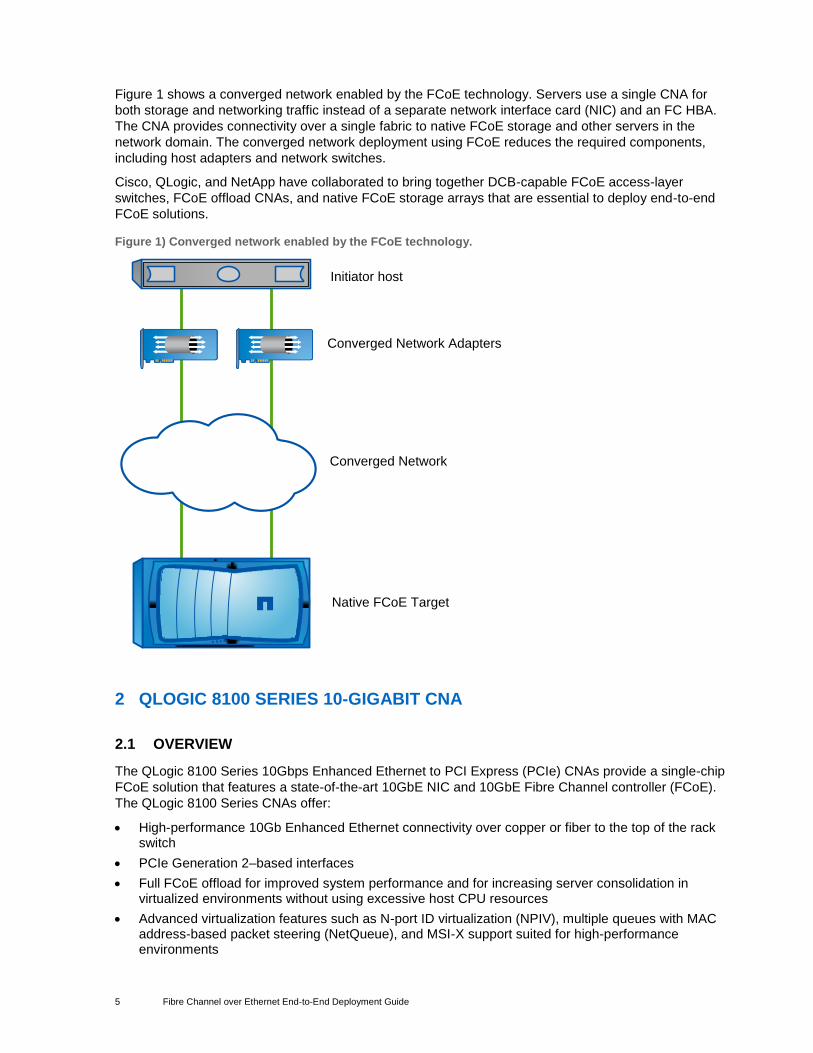
Figure 1 shows a converged network enabled by the FCoE technology. Servers use a single CNA for
both storage and networking traffic instead of a separate network interface card (NIC) and an FC HBA.
The CNA provides connectivity over a single fabric to native FCoE storage and other servers in the
network domain. The converged network deployment using FCoE reduces the required components,
including host adapters and network switches.
Cisco, QLogic, and NetApp have collaborated to bring together DCB-capable FCoE access-layer
switches, FCoE offload CNAs, and native FCoE storage arrays that are essential to deploy end-to-end
FCoE solutions.
Figure 1) Converged network enabled by the FCoE technology.
Initiator host
Converged Network Adapters
Converged Network
Native FCoE Target
2 QLOGIC 8100 SERIES 10-GIGABIT CNA
2.1 OVERVIEW
The QLogic 8100 Series 10Gbps Enhanced Ethernet to PCI Express (PCIe) CNAs provide a single-chip
FCoE solution that features a state-of-the-art 10GbE NIC and 10GbE Fibre Channel controller (FCoE).
The QLogic 8100 Series CNAs offer:
High-performance 10Gb Enhanced Ethernet connectivity over copper or fiber to the top of the rack switch
PCIe Generation 2–based interfaces
Full FCoE offload for improved system performance and for increasing server consolidation in virtualized environments without using excessive host CPU resources
Advanced virtualization features such as N-port ID virtualization (NPIV), multiple queues with MAC address-based packet steering (NetQueue), and MSI-X support suited for high-performance environments
6 Fibre Channel over Ethernet End-to-End Deployment Guide
Superior reduced power consumption; up to one-third the power of first-generation CNAs
Compact form factor; fits in blade servers and high-density storage subsystems
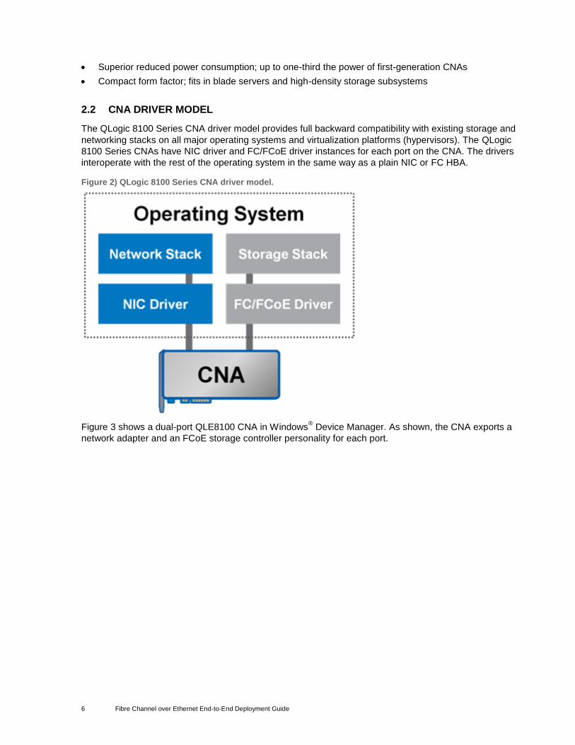
2.2 CNA DRIVER MODEL
The QLogic 8100 Series CNA driver model provides full backward compatibility with existing storage and
networking stacks on all major operating systems and virtualization platforms (hypervisors). The QLogic
8100 Series CNAs have NIC driver and FC/FCoE driver instances for each port on the CNA. The drivers
interoperate with the rest of the operating system in the same way as a plain NIC or FC HBA.
Figure 2) QLogic 8100 Series CNA driver model.
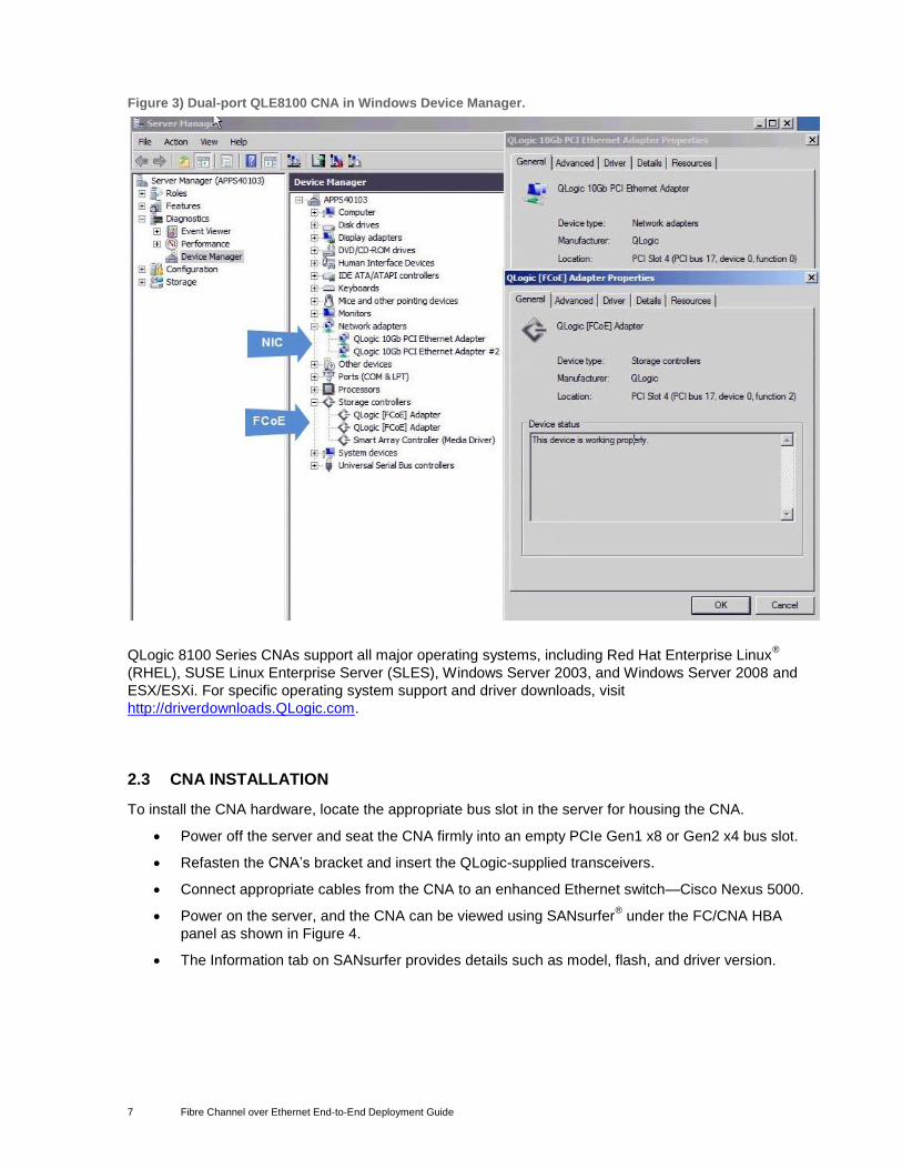
Figure 3 shows a dual-port QLE8100 CNA in Windows® Device Manager. As shown, the CNA exports a
network adapter and an FCoE storage controller personality for each port.
7 Fibre Channel over Ethernet End-to-End Deployment Guide
Figure 3) Dual-port QLE8100 CNA in Windows Device Manager.
QLogic 8100 Series CNAs support all major operating systems, including Red Hat Enterprise Linux®
(RHEL), SUSE Linux Enterprise Server (SLES), Windows Server 2003, and Windows Server 2008 and
ESX/ESXi. For specific operating system support and driver downloads, visit
http://driverdownloads.QLogic.com.
2.3 CNA INSTALLATION
To install the CNA hardware, locate the appropriate bus slot in the server for housing the CNA.
Power off the server and seat the CNA firmly into an empty PCIe Gen1 x8 or Gen2 x4 bus slot.
Refasten the CNA’s bracket and insert the QLogic-supplied transceivers.
Connect appropriate cables from the CNA to an enhanced Ethernet switch—Cisco Nexus 5000.
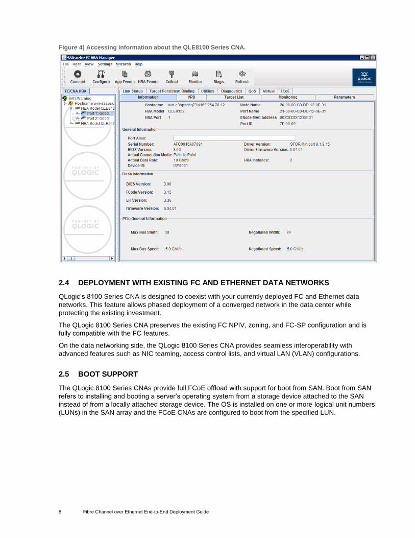
Power on the server, and the CNA can be viewed using SANsurfer® under the FC/CNA HBA
panel as shown in Figure 4.
The Information tab on SANsurfer provides details such as model, flash, and driver version.
8 Fibre Channel over Ethernet End-to-End Deployment Guide
Figure 4) Accessing information about the QLE8100 Series CNA.
2.4 DEPLOYMENT WITH EXISTING FC AND ETHERNET DATA NETWORKS
QLogic’s 8100 Series CNA is designed to coexist with your currently deployed FC and Ethernet data
networks. This feature allows phased deployment of a converged network in the data center while
protecting the existing investment.
The QLogic 8100 Series CNA preserves the existing FC NPIV, zoning, and FC-SP configuration and is
fully compatible with the FC features.
On the data networking side, the QLogic 8100 Series CNA provides seamless interoperability with
advanced features such as NIC teaming, access control lists, and virtual LAN (VLAN) configurations.
2.5 BOOT SUPPORT
The QLogic 8100 Series CNAs provide full FCoE offload with support for boot from SAN. Boot from SAN
refers to installing and booting a server’s operating system from a storage device attached to the SAN
instead of from a locally attached storage device. The OS is installed on one or more logical unit numbers
(LUNs) in the SAN array and the FCoE CNAs are configured to boot from the specified LUN.
9 Fibre Channel over Ethernet End-to-End Deployment Guide
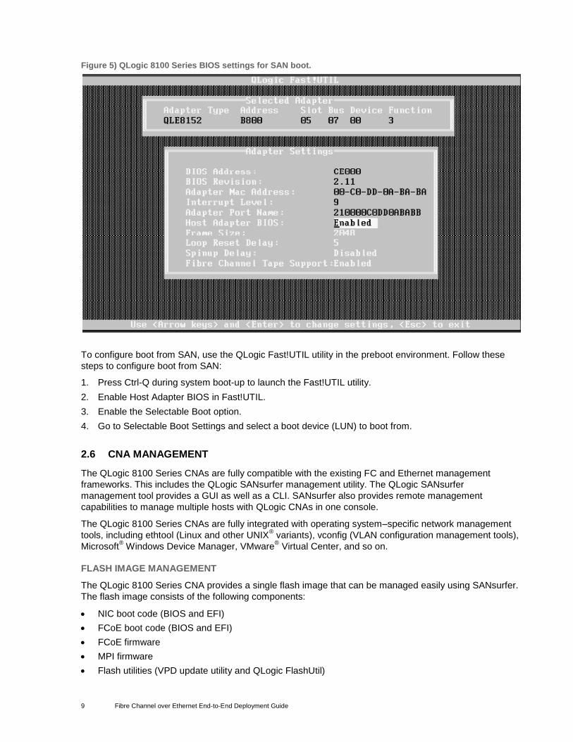
Figure 5) QLogic 8100 Series BIOS settings for SAN boot.
To configure boot from SAN, use the QLogic Fast!UTIL utility in the preboot environment. Follow these
steps to configure boot from SAN:
1. Press Ctrl-Q during system boot-up to launch the Fast!UTIL utility.
2. Enable Host Adapter BIOS in Fast!UTIL.
3. Enable the Selectable Boot option.
4. Go to Selectable Boot Settings and select a boot device (LUN) to boot from.
2.6 CNA MANAGEMENT
The QLogic 8100 Series CNAs are fully compatible with the existing FC and Ethernet management
frameworks. This includes the QLogic SANsurfer management utility. The QLogic SANsurfer
management tool provides a GUI as well as a CLI. SANsurfer also provides remote management
capabilities to manage multiple hosts with QLogic CNAs in one console.
The QLogic 8100 Series CNAs are fully integrated with operating system–specific network management
tools, including ethtool (Linux and other UNIX® variants), vconfig (VLAN configuration management tools),
Microsoft® Windows Device Manager, VMware
® Virtual Center, and so on.
FLASH IMAGE MANAGEMENT
The QLogic 8100 Series CNA provides a single flash image that can be managed easily using SANsurfer.
The flash image consists of the following components:
NIC boot code (BIOS and EFI)
FCoE boot code (BIOS and EFI)
FCoE firmware
MPI firmware
Flash utilities (VPD update utility and QLogic FlashUtil)
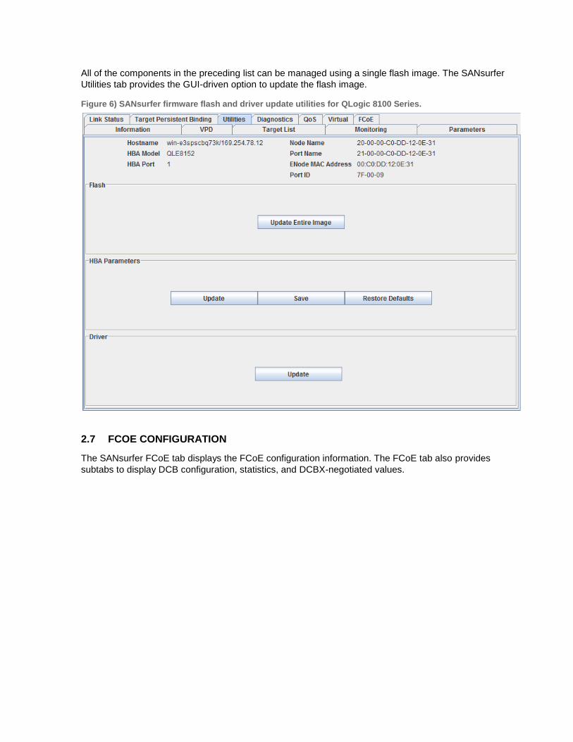
All of the components in the preceding list can be managed using a single flash image. The SANsurfer
Utilities tab provides the GUI-driven option to update the flash image.
Figure 6) SANsurfer firmware flash and driver update utilities for QLogic 8100 Series.
2.7 FCOE CONFIGURATION
The SANsurfer FCoE tab displays the FCoE configuration information. The FCoE tab also provides
subtabs to display DCB configuration, statistics, and DCBX-negotiated values.
11 Fibre Channel over Ethernet End-to-End Deployment Guide
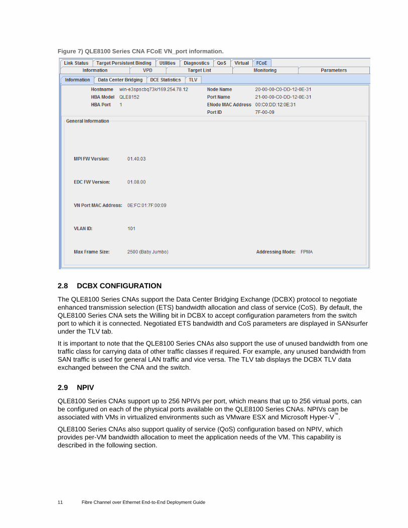
Figure 7) QLE8100 Series CNA FCoE VN_port information.
2.8 DCBX CONFIGURATION
The QLE8100 Series CNAs support the Data Center Bridging Exchange (DCBX) protocol to negotiate
enhanced transmission selection (ETS) bandwidth allocation and class of service (CoS). By default, the
QLE8100 Series CNA sets the Willing bit in DCBX to accept configuration parameters from the switch
port to which it is connected. Negotiated ETS bandwidth and CoS parameters are displayed in SANsurfer
under the TLV tab.
It is important to note that the QLE8100 Series CNAs also support the use of unused bandwidth from one
traffic class for carrying data of other traffic classes if required. For example, any unused bandwidth from
SAN traffic is used for general LAN traffic and vice versa. The TLV tab displays the DCBX TLV data
exchanged between the CNA and the switch.
2.9 NPIV
QLE8100 Series CNAs support up to 256 NPIVs per port, which means that up to 256 virtual ports, can
be configured on each of the physical ports available on the QLE8100 Series CNAs. NPIVs can be
associated with VMs in virtualized environments such as VMware ESX and Microsoft Hyper-V™
.
QLE8100 Series CNAs also support quality of service (QoS) configuration based on NPIV, which
provides per-VM bandwidth allocation to meet the application needs of the VM. This capability is
described in the following section.
12 Fibre Channel over Ethernet End-to-End Deployment Guide
2.10 QOS
QLE8100 Series CNAs support two levels of QoS configuration. The first level based on ETS protocol
provides bandwidth allocation based on traffic type (SAN and LAN). Within the allocated bandwidth limit
for SAN traffic, QLE8100 Series CNAs support NPIV-based QoS configuration on a per-virtual-port basis.
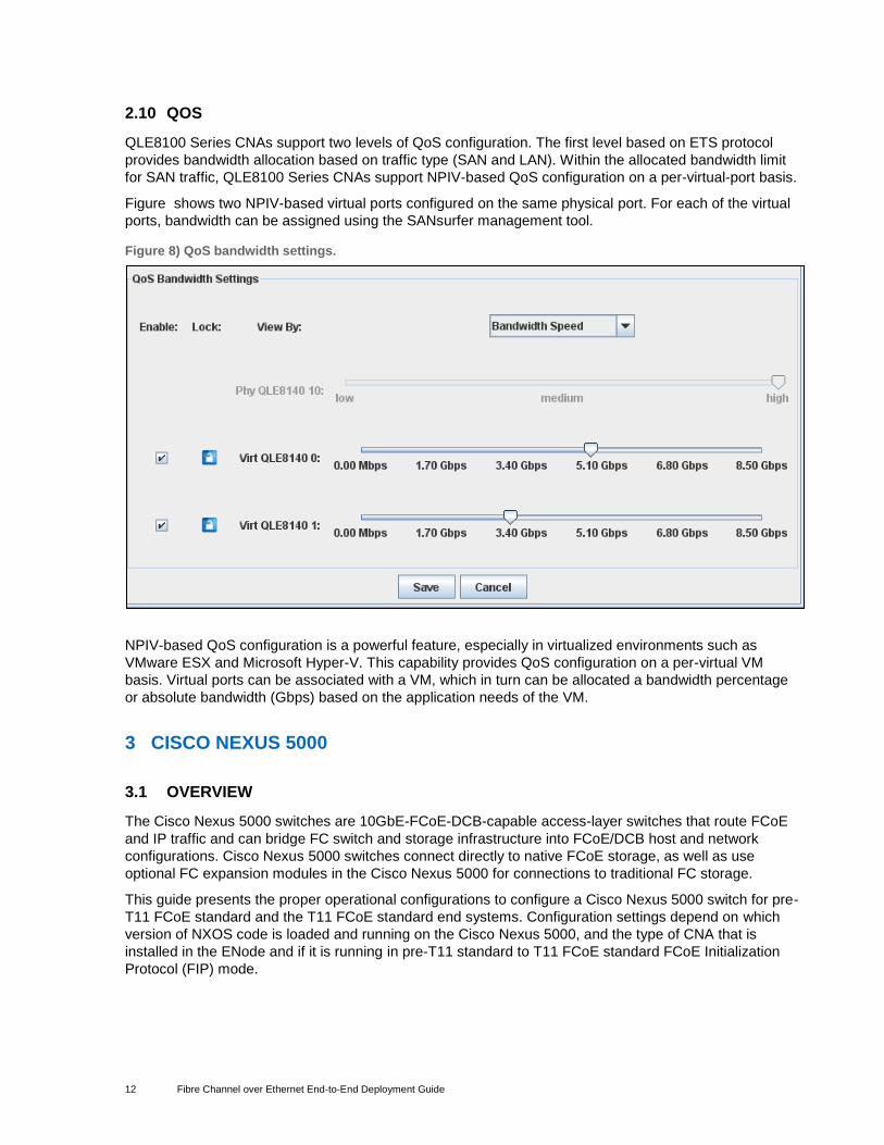
Figure shows two NPIV-based virtual ports configured on the same physical port. For each of the virtual
ports, bandwidth can be assigned using the SANsurfer management tool.
Figure 8) QoS bandwidth settings.
NPIV-based QoS configuration is a powerful feature, especially in virtualized environments such as
VMware ESX and Microsoft Hyper-V. This capability provides QoS configuration on a per-virtual VM
basis. Virtual ports can be associated with a VM, which in turn can be allocated a bandwidth percentage
or absolute bandwidth (Gbps) based on the application needs of the VM.
3 CISCO NEXUS 5000
3.1 OVERVIEW
The Cisco Nexus 5000 switches are 10GbE-FCoE-DCB-capable access-layer switches that route FCoE
and IP traffic and can bridge FC switch and storage infrastructure into FCoE/DCB host and network
configurations. Cisco Nexus 5000 switches connect directly to native FCoE storage, as well as use
optional FC expansion modules in the Cisco Nexus 5000 for connections to traditional FC storage.
This guide presents the proper operational configurations to configure a Cisco Nexus 5000 switch for pre-
T11 FCoE standard and the T11 FCoE standard end systems. Configuration settings depend on which
version of NXOS code is loaded and running on the Cisco Nexus 5000, and the type of CNA that is
installed in the ENode and if it is running in pre-T11 standard to T11 FCoE standard FCoE Initialization
Protocol (FIP) mode.
13 Fibre Channel over Ethernet End-to-End Deployment Guide
3.2 INITIAL CONFIGURATION
Configurations are shown using the switch CLI. Some configuration settings can also be set using the
Cisco Device Manager GUI that comes with the switch.
Configurations are based on the network topology shown in Figure 1.
The Cisco NXOS release used in this paper is 5.0(2)N2(1). The basic steps for configuring FCoE are the
same as for prior versions and this document can be used as a guide. However, 5.0(2)N2(1) does include
some features not available in earlier versions and some steps may have minor changes. Please consult
the Cisco Nexus documentation for your version of NXOS for specifics.
The Cisco Nexus 5000 series switch requires a console connected to the switch for the first time to apply
the hostname and password for the new switch. The typical local console connection is 9600 8N1. After
the initial setup script is complete, SSH, telnet, or the Cisco Device Manager GUI can be used to access
the Cisco Nexus 5000 switch and complete the FCoE configuration.
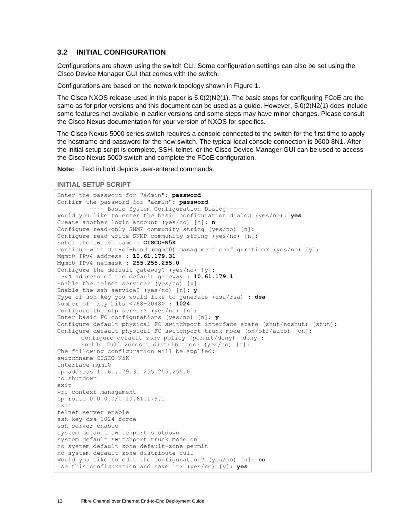
Note: Text in bold depicts user-entered commands.
INITIAL SETUP SCRIPT
Enter the password for "admin": password
Confirm the password for "admin": password
---- Basic System Configuration Dialog ----
Would you like to enter the basic configuration dialog (yes/no): yes
Create another login account (yes/no) [n]: n
Configure read-only SNMP community string (yes/no) [n]:
Configure read-write SNMP community string (yes/no) [n]:
Enter the switch name : CISCO-N5K
Continue with Out-of-band (mgmt0) management configuration? (yes/no) [y]:
Mgmt0 IPv4 address : 10.61.179.31
Mgmt0 IPv4 netmask : 255.255.255.0
Configure the default gateway? (yes/no) [y]:
IPv4 address of the default gateway : 10.61.179.1
Enable the telnet service? (yes/no) [y]:
Enable the ssh service? (yes/no) [n]: y
Type of ssh key you would like to generate (dsa/rsa) : dsa
Number of key bits <768-2048> : 1024
Configure the ntp server? (yes/no) [n]:
Enter basic FC configurations (yes/no) [n]: y
Configure default physical FC switchport interface state (shut/noshut) [shut]:
Configure default physical FC switchport trunk mode (on/off/auto) [on]:
Configure default zone policy (permit/deny) [deny]:
Enable full zoneset distribution? (yes/no) [n]:
The following configuration will be applied:
switchname CISCO-N5K
interface mgmt0
ip address 10.61.179.31 255.255.255.0
no shutdown
exit
vrf context management
ip route 0.0.0.0/0 10.61.179.1
exit
telnet server enable
ssh key dsa 1024 force
ssh server enable
system default switchport shutdown
system default switchport trunk mode on
no system default zone default-zone permit
no system default zone distribute full
Would you like to edit the configuration? (yes/no) [n]: no
Use this configuration and save it? (yes/no) [y]: yes
14 Fibre Channel over Ethernet End-to-End Deployment Guide
[########################################] 100%
Note: Key items in the preceding example were configured when the setup script was used. If the script is not used, you need to use the CLI to configure these key items.
SNMP MANAGEMENT
CISCO-N5K-A(config)# snmp-server user admin network-admin auth md5
0x2e54a976620cfd7ef00eb700ef78881f priv 0x2e54a976620cfd7ef00eb700ef78881f
localizedkey
VRF DEFAULT ROUTE FOR OOB MANAGEMENT NETWORK
CISCO-N5K-A(config)# vrf context management
CISCO-N5K-A(config)# ip route 0.0.0.0/0 10.61.179.1
3.3 LICENSE INSTALLATION
An FCoE license is required to keep FCoE enabled if running past the 90-day grace period.
CISCO-N5K-A# install license bootflash://license.lic
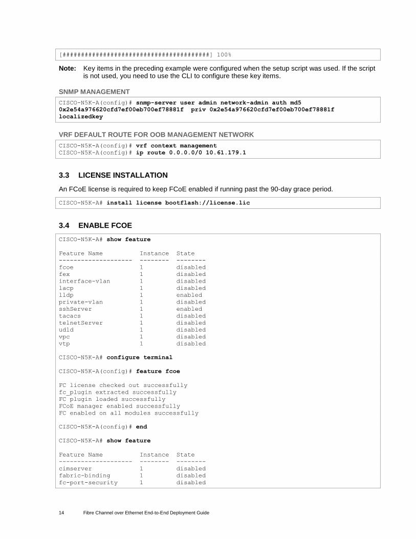
3.4 ENABLE FCOE
CISCO-N5K-A# show feature
Feature Name Instance State
-------------------- -------- --------
fcoe 1 disabled
fex 1 disabled
interface-vlan 1 disabled
lacp 1 disabled
lldp 1 enabled
private-vlan 1 disabled
sshServer 1 enabled
tacacs 1 disabled
telnetServer 1 disabled
udld 1 disabled
vpc 1 disabled
vtp 1 disabled
CISCO-N5K-A# configure terminal
CISCO-N5K-A(config)# feature fcoe
FC license checked out successfully
fc_plugin extracted successfully
FC plugin loaded successfully
FCoE manager enabled successfully
FC enabled on all modules successfully
CISCO-N5K-A(config)# end
CISCO-N5K-A# show feature
Feature Name Instance State
-------------------- -------- --------
cimserver 1 disabled
fabric-binding 1 disabled
fc-port-security 1 disabled
15 Fibre Channel over Ethernet End-to-End Deployment Guide
fcoe 1 enabled
fcsp 1 disabled
fex 1 disabled
fport-channel-trunk 1 disabled
http-server 1 disabled
interface-vlan 1 disabled
lacp 1 disabled
lldp 1 enabled
npiv 1 disabled
npv 1 disabled
port_track 1 disabled
private-vlan 1 disabled
sshServer 1 enabled
tacacs 1 disabled
telnetServer 1 disabled
udld 1 disabled
vpc 1 disabled
vtp 1 disabled
CISCO-N5K-A(config)# show license usage
Feature Ins Lic Status Expiry Date Comments
Count
--------------------------------------------------------------------------------
FM_SERVER_PKG Yes - Unused Never -
ENTERPRISE_PKG Yes - Unused Never -
FC_FEATURES_PKG Yes - In use Never -
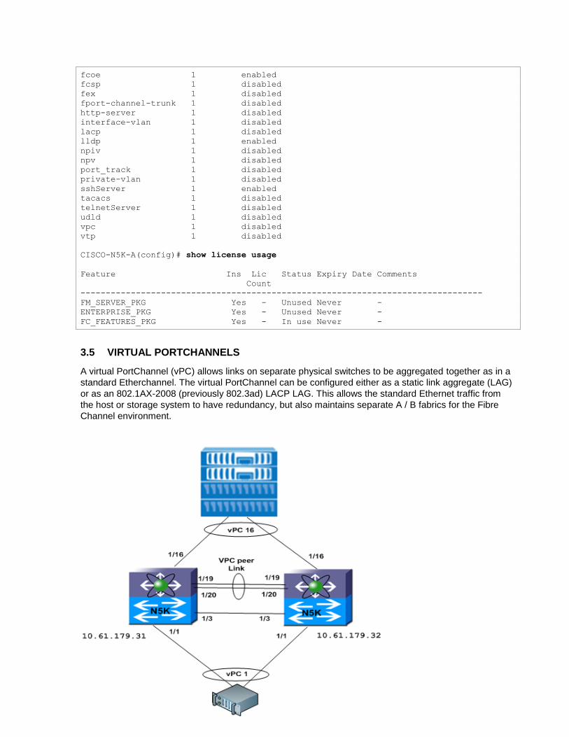
3.5 VIRTUAL PORTCHANNELS
A virtual PortChannel (vPC) allows links on separate physical switches to be aggregated together as in a
standard Etherchannel. The virtual PortChannel can be configured either as a static link aggregate (LAG)
or as an 802.1AX-2008 (previously 802.3ad) LACP LAG. This allows the standard Ethernet traffic from
the host or storage system to have redundancy, but also maintains separate A / B fabrics for the Fibre
Channel environment.
16 Fibre Channel over Ethernet End-to-End Deployment Guide
ENABLE VPC AND LACP
The LACP feature must be enabled to use LACP-style PortChannels. LACP is recommended over static
PortChannels due to improved link-state checking.
CISCO-N5K-A# feature lacp
CISCO-N5K-A# feature vpc
Repeat on the second vPC member switch.
CONFIGURE THE VPC PEER LINK
These commands set up the virtual PortChannel domain and peer links. Multiple peer links are
recommended for redundancy.
Note: Determine that the vPC peer link is not configured to transport any VLANs associated with FCoE VSANs.
CISCO-N5K-A# vpc domain 1000
CISCO-N5K-A# peer-keepalive destination 10.61.179.32
CISCO-N5K-A# interface port-channel 100
CISCO-N5K-A# vpc peer-link
CISCO-N5K-A# interface Ethernet 1/19-20
CISCO-N5K-A# switchport mode trunk
CISCO-N5K-A# switchport trunk allowed vlan 1
CISCO-N5K-A# channel-group 100 mode active
Repeat on the second switch, using the appropriate IP address and Ethernet interfaces.
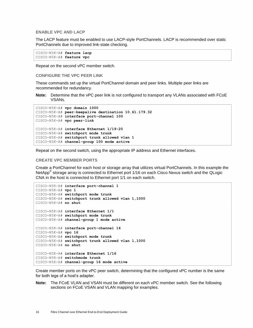
CREATE VPC MEMBER PORTS
Create a PortChannel for each host or storage array that utilizes virtual PortChannels. In this example the
NetApp® storage array is connected to Ethernet port 1/16 on each Cisco Nexus switch and the QLogic
CNA in the host is connected to Ethernet port 1/1 on each switch.
CISCO-N5K-A# interface port-channel 1
CISCO-N5K-A# vpc 1
CISCO-N5K-A# switchport mode trunk
CISCO-N5K-A# switchport trunk allowed vlan 1,1000
CISCO-N5K-A# no shut
CISCO-N5K-A# interface Ethernet 1/1
CISCO-N5K-A# switchport mode trunk
CISCO-N5K-A# channel-group 1 mode active
CISCO-N5K-A# interface port-channel 16
CISCO-N5K-A# vpc 16
CISCO-N5K-A# switchport mode trunk
CISCO-N5K-A# switchport trunk allowed vlan 1,1000
CISCO-N5K-A# no shut
CISCO-N5K-A# interface Ethernet 1/16
CISCO-N5K-A# switchmode trunk
CISCO-N5K-A# channel-group 16 mode active
Create member ports on the vPC peer switch, determining that the configured vPC number is the same
for both legs of a host’s adapter.
Note: The FCoE VLAN and VSAN must be different on each vPC member switch. See the following sections on FCoE VSAN and VLAN mapping for examples.
17 Fibre Channel over Ethernet End-to-End Deployment Guide
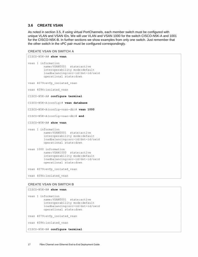
3.6 CREATE VSAN
As noted in section 3.5, if using virtual PortChannels, each member switch must be configured with
unique VLAN and VSAN IDs. We will use VLAN and VSAN 1000 for the switch CISCO-N5K-A and 1001
for the CISCO-N5K-B. In further sections we show examples from only one switch. Just remember that
the other switch in the vPC pair must be configured correspondingly.
CREATE VSAN ON SWITCH A
CISCO-N5K-A# show vsan
vsan 1 information
name:VSAN0001 state:active
interoperability mode:default
loadbalancing:src-id/dst-id/oxid
operational state:down
vsan 4079:evfp_isolated_vsan
vsan 4094:isolated_vsan
CISCO-N5K-A# configure terminal
CISCO-N5K-A(config)# vsan database
CISCO-N5K-A(config-vsan-db)# vsan 1000
CISCO-N5K-A(config-vsan-db)# end
CISCO-N5K-A# show vsan
vsan 1 information
name:VSAN0001 state:active
interoperability mode:default
loadbalancing:src-id/dst-id/oxid
operational state:down
vsan 1000 information
name:VSAN1000 state:active
interoperability mode:default
loadbalancing:src-id/dst-id/oxid
operational state:down
vsan 4079:evfp_isolated_vsan
vsan 4094:isolated_vsan
CREATE VSAN ON SWITCH B
CISCO-N5K-B# show vsan
vsan 1 information
name:VSAN0001 state:active
interoperability mode:default
loadbalancing:src-id/dst-id/oxid
operational state:down
vsan 4079:evfp_isolated_vsan
vsan 4094:isolated_vsan
CISCO-N5K-B# configure terminal
18 Fibre Channel over Ethernet End-to-End Deployment Guide
CISCO-N5K-B(config)# vsan database
CISCO-N5K-B(config-vsan-db)# vsan 1001
CISCO-N5K-B(config-vsan-db)# end
CISCO-N5K-B# show vsan
vsan 1 information
name:VSAN0001 state:active
interoperability mode:default
loadbalancing:src-id/dst-id/oxid
operational state:down
vsan 1000 information
name:VSAN1001 state:active
interoperability mode:default
loadbalancing:src-id/dst-id/oxid
operational state:down
vsan 4079:evfp_isolated_vsan
vsan 4094:isolated_vsan
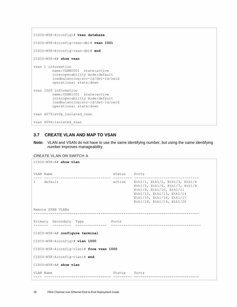
3.7 CREATE VLAN AND MAP TO VSAN
Note: VLAN and VSAN do not have to use the same identifying number, but using the same identifying number improves manageability.
CREATE VLAN ON SWITCH A
CISCO-N5K-A# show vlan
VLAN Name Status Ports
---- -------------------------------- --------- -------------------------------
1 default active Eth1/1, Eth1/2, Eth1/3, Eth1/4
Eth1/5, Eth1/6, Eth1/7, Eth1/8
Eth1/9, Eth1/10, Eth1/11
Eth1/12, Eth1/13, Eth1/14
Eth1/15, Eth1/16, Eth1/17
Eth1/18, Eth1/19, Eth1/20
Remote SPAN VLANs
-------------------------------------------------------------------------------
Primary Secondary Type Ports
------- --------- --------------- -------------------------------------------
CISCO-N5K-A# configure terminal
CISCO-N5K-A(config)# vlan 1000
CISCO-N5K-A(config-vlan)# fcoe vsan 1000
CISCO-N5K-A(config-vlan)# end
CISCO-N5K-A# show vlan
VLAN Name Status Ports
---- -------------------------------- --------- -------------------------------
19 Fibre Channel over Ethernet End-to-End Deployment Guide
1 default active Eth1/1, Eth1/2, Eth1/3, Eth1/4
Eth1/5, Eth1/6, Eth1/7, Eth1/8
Eth1/9, Eth1/10, Eth1/11
Eth1/12, Eth1/13, Eth1/14
Eth1/15, Eth1/16, Eth1/17
Eth1/18, Eth1/19, Eth1/20
1000 VLAN1000 active
VLAN Name Status Ports
---- -------------------------------- --------- -------------------------------
Remote SPAN VLANs
-------------------------------------------------------------------------------
Primary Secondary Type Ports
------- --------- --------------- -------------------------------------------
CISCO-N5K-A# show vlan fcoe
VLAN VSAN Status
-------- -------- --------
1000 1000 Operational
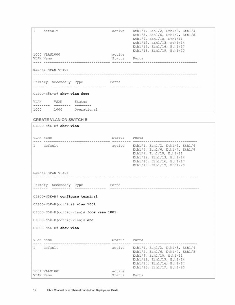
CREATE VLAN ON SWITCH B
CISCO-N5K-B# show vlan
VLAN Name Status Ports
---- -------------------------------- --------- -------------------------------
1 default active Eth1/1, Eth1/2, Eth1/3, Eth1/4
Eth1/5, Eth1/6, Eth1/7, Eth1/8
Eth1/9, Eth1/10, Eth1/11
Eth1/12, Eth1/13, Eth1/14
Eth1/15, Eth1/16, Eth1/17
Eth1/18, Eth1/19, Eth1/20
Remote SPAN VLANs
-------------------------------------------------------------------------------
Primary Secondary Type Ports
------- --------- --------------- -------------------------------------------
CISCO-N5K-B# configure terminal
CISCO-N5K-B(config)# vlan 1001
CISCO-N5K-B(config-vlan)# fcoe vsan 1001
CISCO-N5K-B(config-vlan)# end
CISCO-N5K-B# show vlan
VLAN Name Status Ports
---- -------------------------------- --------- -------------------------------
1 default active Eth1/1, Eth1/2, Eth1/3, Eth1/4
Eth1/5, Eth1/6, Eth1/7, Eth1/8
Eth1/9, Eth1/10, Eth1/11
Eth1/12, Eth1/13, Eth1/14
Eth1/15, Eth1/16, Eth1/17
Eth1/18, Eth1/19, Eth1/20
1001 VLAN1001 active
VLAN Name Status Ports
20 Fibre Channel over Ethernet End-to-End Deployment Guide
---- -------------------------------- --------- -------------------------------
Remote SPAN VLANs
-------------------------------------------------------------------------------
Primary Secondary Type Ports
------- --------- --------------- -------------------------------------------
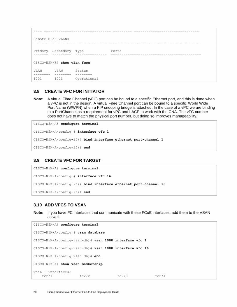
CISCO-N5K-B# show vlan fcoe
VLAN VSAN Status
-------- -------- --------
1001 1001 Operational
3.8 CREATE VFC FOR INITIATOR
Note: A virtual Fibre Channel (vFC) port can be bound to a specific Ethernet port, and this is done when a vPC is not in the design. A virtual Fibre Channel port can be bound to a specific World Wide Port Name (WWPN) when a FIP snooping bridge is attached. In the case of a vPC we are binding to a PortChannel as a requirement for vPC and LACP to work with the CNA. The vFC number does not have to match the physical port number, but doing so improves manageability.
CISCO-N5K-A# configure terminal
CISCO-N5K-A(config)# interface vfc 1
CISCO-N5K-A(config-if)# bind interface ethernet port-channel 1
CISCO-N5K-A(config-if)# end
3.9 CREATE VFC FOR TARGET
CISCO-N5K-A# configure terminal
CISCO-N5K-A(config)# interface vfc 16
CISCO-N5K-A(config-if)# bind interface ethernet port-channel 16
CISCO-N5K-A(config-if)# end
3.10 ADD VFCS TO VSAN
Note: If you have FC interfaces that communicate with these FCoE interfaces, add them to the VSAN as well.
CISCO-N5K-A# configure terminal
CISCO-N5K-A(config)# vsan database
CISCO-N5K-A(config-vsan-db)# vsan 1000 interface vfc 1
CISCO-N5K-A(config-vsan-db)# vsan 1000 interface vfc 16
CISCO-N5K-A(config-vsan-db)# end
CISCO-N5K-A# show vsan membership
vsan 1 interfaces:
fc2/1 fc2/2 fc2/3 fc2/4

21 Fibre Channel over Ethernet End-to-End Deployment Guide
fc2/5 fc2/6 fc2/7 fc2/8
vsan 1000 interfaces:
vfc1 vfc16
vsan 4079(evfp_isolated_vsan) interfaces:
vsan 4094(isolated_vsan) interfaces:
22 Fibre Channel over Ethernet End-to-End Deployment Guide
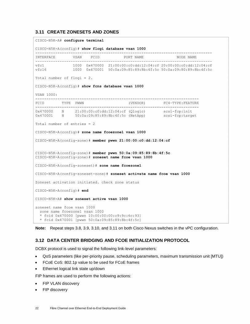
3.11 CREATE ZONESETS AND ZONES
CISCO-N5K-A# configure terminal
CISCO-N5K-A(config)# show flogi database vsan 1000
--------------------------------------------------------------------------------
INTERFACE VSAN FCID PORT NAME NODE NAME
--------------------------------------------------------------------------------
vfc1 1000 0x470000 21:00:00:c0:dd:12:04:cf 20:00:00:c0:dd:12:04:cf
vfc16 1000 0x470001 50:0a:09:85:89:8b:4f:5c 50:0a:09:80:89:8b:4f:5c
Total number of flogi = 2.
CISCO-N5K-A(config)# show fcns database vsan 1000
VSAN 1000:
--------------------------------------------------------------------------
FCID TYPE PWWN (VENDOR) FC4-TYPE:FEATURE
--------------------------------------------------------------------------
0x470000 N 21:00:00:c0:dd:12:04:cf (Qlogic) scsi-fcp:init
0x470001 N 50:0a:09:85:89:8b:4f:5c (NetApp) scsi-fcp:target
Total number of entries = 2
CISCO-N5K-A(config)# zone name fcoezone1 vsan 1000
CISCO-N5K-A(config-zone)# member pwwn 21:00:00:c0:dd:12:04:cf
CISCO-N5K-A(config-zone)# member pwwn 50:0a:09:85:89:8b:4f:5c
CISCO-N5K-A(config-zone)# zoneset name fcoe vsan 1000
CISCO-N5K-A(config-zoneset)# zone name fcoezone1
CISCO-N5K-A(config-zoneset-zone)# zoneset activate name fcoe vsan 1000
Zoneset activation initiated. check zone status
CISCO-N5K-A(config)# end
CISCO-N5K-A# show zoneset active vsan 1000
zoneset name fcoe vsan 1000
zone name fcoezone1 vsan 1000
* fcid 0x470000 [pwwn 10:00:00:00:c9:9c:6c:93]
* fcid 0x470001 [pwwn 50:0a:09:85:89:8b:4f:5c]
Note: Repeat steps 3.8, 3.9, 3.10, and 3.11 on both Cisco Nexus switches in the vPC configuration.
3.12 DATA CENTER BRIDGING AND FCOE INITIALIZATION PROTOCOL
DCBX protocol is used to signal the following link-level parameters:
QoS parameters (like per-priority pause, scheduling parameters, maximum transmission unit [MTU])
FCoE CoS: 802.1p value to be used for FCoE frames
Ethernet logical link state up/down
FIP frames are used to perform the following actions:
FIP VLAN discovery
FIP discovery
23 Fibre Channel over Ethernet End-to-End Deployment Guide
FCoE virtual link instantiation
FCoE virtual link maintenance
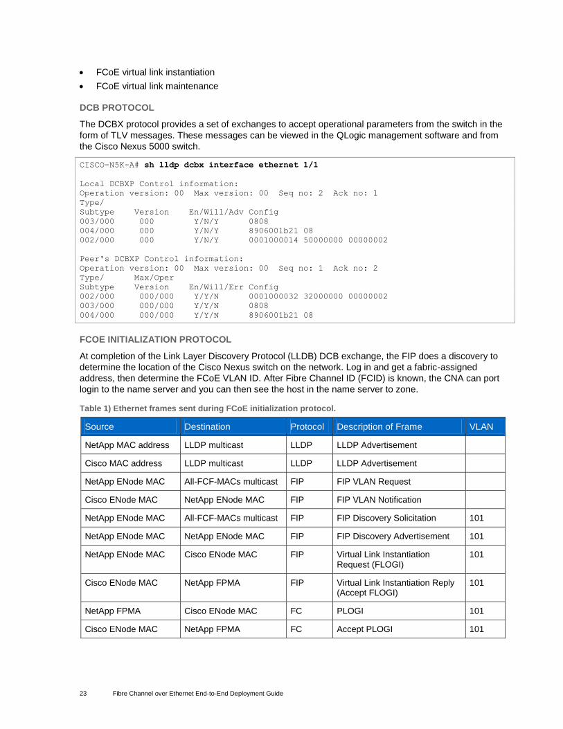
DCB PROTOCOL
The DCBX protocol provides a set of exchanges to accept operational parameters from the switch in the
form of TLV messages. These messages can be viewed in the QLogic management software and from
the Cisco Nexus 5000 switch.
CISCO-N5K-A# sh lldp dcbx interface ethernet 1/1
Local DCBXP Control information:
Operation version: 00 Max version: 00 Seq no: 2 Ack no: 1
Type/
Subtype Version En/Will/Adv Config
003/000 000 Y/N/Y 0808
004/000 000 Y/N/Y 8906001b21 08
002/000 000 Y/N/Y 0001000014 50000000 00000002
Peer's DCBXP Control information:
Operation version: 00 Max version: 00 Seq no: 1 Ack no: 2
Type/ Max/Oper
Subtype Version En/Will/Err Config
002/000 000/000 Y/Y/N 0001000032 32000000 00000002
003/000 000/000 Y/Y/N 0808
004/000 000/000 Y/Y/N 8906001b21 08
FCOE INITIALIZATION PROTOCOL
At completion of the Link Layer Discovery Protocol (LLDB) DCB exchange, the FIP does a discovery to
determine the location of the Cisco Nexus switch on the network. Log in and get a fabric-assigned
address, then determine the FCoE VLAN ID. After Fibre Channel ID (FCID) is known, the CNA can port
login to the name server and you can then see the host in the name server to zone.
Table 1) Ethernet frames sent during FCoE initialization protocol.
Source Destination Protocol Description of Frame VLAN
NetApp MAC address LLDP multicast LLDP LLDP Advertisement
Cisco MAC address LLDP multicast LLDP LLDP Advertisement
NetApp ENode MAC All-FCF-MACs multicast FIP FIP VLAN Request
Cisco ENode MAC NetApp ENode MAC FIP FIP VLAN Notification
NetApp ENode MAC All-FCF-MACs multicast FIP FIP Discovery Solicitation 101
NetApp ENode MAC NetApp ENode MAC FIP FIP Discovery Advertisement 101
NetApp ENode MAC Cisco ENode MAC FIP Virtual Link Instantiation Request (FLOGI)
101
Cisco ENode MAC NetApp FPMA FIP Virtual Link Instantiation Reply (Accept FLOGI)
101
NetApp FPMA Cisco ENode MAC FC PLOGI 101
Cisco ENode MAC NetApp FPMA FC Accept PLOGI 101
24 Fibre Channel over Ethernet End-to-End Deployment Guide
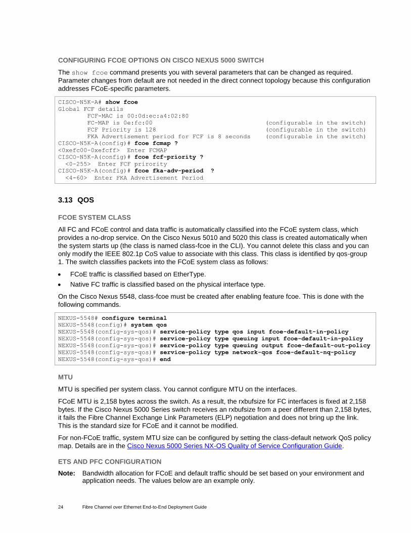
CONFIGURING FCOE OPTIONS ON CISCO NEXUS 5000 SWITCH
The show fcoe command presents you with several parameters that can be changed as required.
Parameter changes from default are not needed in the direct connect topology because this configuration
addresses FCoE-specific parameters.
CISCO-N5K-A# show fcoe
Global FCF details
FCF-MAC is 00:0d:ec:a4:02:80
FC-MAP is 0e:fc:00 (configurable in the switch)
FCF Priority is 128 (configurable in the switch)
FKA Advertisement period for FCF is 8 seconds (configurable in the switch)
CISCO-N5K-A(config)# fcoe fcmap ?
<0xefc00-0xefcff> Enter FCMAP
CISCO-N5K-A(config)# fcoe fcf-priority ?
<0-255> Enter FCF prirority
CISCO-N5K-A(config)# fcoe fka-adv-period ?
<4-60> Enter FKA Advertisement Period
3.13 QOS
FCOE SYSTEM CLASS
All FC and FCoE control and data traffic is automatically classified into the FCoE system class, which
provides a no-drop service. On the Cisco Nexus 5010 and 5020 this class is created automatically when
the system starts up (the class is named class-fcoe in the CLI). You cannot delete this class and you can
only modify the IEEE 802.1p CoS value to associate with this class. This class is identified by qos-group
1. The switch classifies packets into the FCoE system class as follows:
FCoE traffic is classified based on EtherType.
Native FC traffic is classified based on the physical interface type.
On the Cisco Nexus 5548, class-fcoe must be created after enabling feature fcoe. This is done with the
following commands.
NEXUS-5548# configure terminal
NEXUS-5548(config)# system qos
NEXUS-5548(config-sys-qos)# service-policy type qos input fcoe-default-in-policy
NEXUS-5548(config-sys-qos)# service-policy type queuing input fcoe-default-in-policy
NEXUS-5548(config-sys-qos)# service-policy type queuing output fcoe-default-out-policy
NEXUS-5548(config-sys-qos)# service-policy type network-qos fcoe-default-nq-policy
NEXUS-5548(config-sys-qos)# end
MTU
MTU is specified per system class. You cannot configure MTU on the interfaces.
FCoE MTU is 2,158 bytes across the switch. As a result, the rxbufsize for FC interfaces is fixed at 2,158
bytes. If the Cisco Nexus 5000 Series switch receives an rxbufsize from a peer different than 2,158 bytes,
it fails the Fibre Channel Exchange Link Parameters (ELP) negotiation and does not bring up the link.
This is the standard size for FCoE and it cannot be modified.
For non-FCoE traffic, system MTU size can be configured by setting the class-default network QoS policy
map. Details are in the Cisco Nexus 5000 Series NX-OS Quality of Service Configuration Guide.
ETS AND PFC CONFIGURATION
Note: Bandwidth allocation for FCoE and default traffic should be set based on your environment and application needs. The values below are an example only.
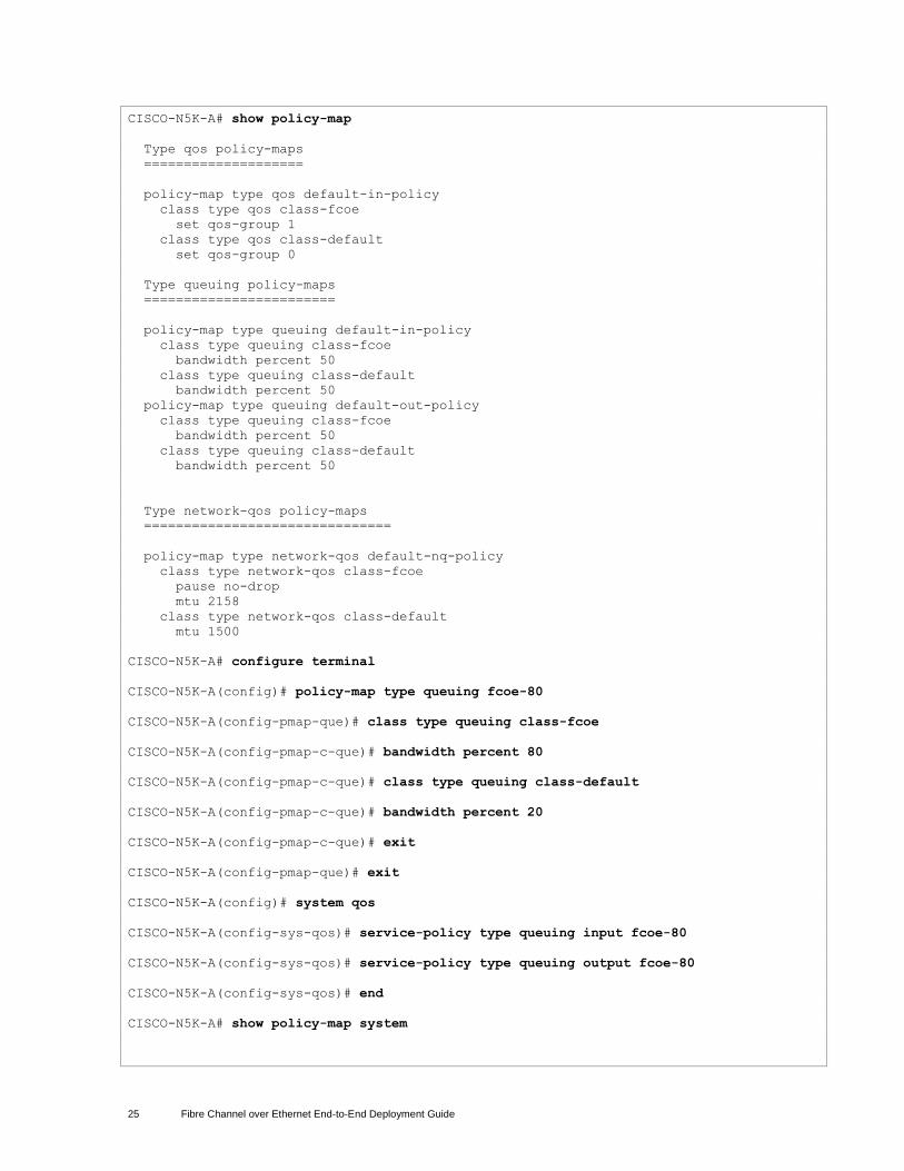
25 Fibre Channel over Ethernet End-to-End Deployment Guide
CISCO-N5K-A# show policy-map
Type qos policy-maps
====================
policy-map type qos default-in-policy
class type qos class-fcoe
set qos-group 1
class type qos class-default
set qos-group 0
Type queuing policy-maps
========================
policy-map type queuing default-in-policy
class type queuing class-fcoe
bandwidth percent 50
class type queuing class-default
bandwidth percent 50
policy-map type queuing default-out-policy
class type queuing class-fcoe
bandwidth percent 50
class type queuing class-default
bandwidth percent 50
Type network-qos policy-maps
===============================
policy-map type network-qos default-nq-policy
class type network-qos class-fcoe
pause no-drop
mtu 2158
class type network-qos class-default
mtu 1500
CISCO-N5K-A# configure terminal
CISCO-N5K-A(config)# policy-map type queuing fcoe-80
CISCO-N5K-A(config-pmap-que)# class type queuing class-fcoe
CISCO-N5K-A(config-pmap-c-que)# bandwidth percent 80
CISCO-N5K-A(config-pmap-c-que)# class type queuing class-default
CISCO-N5K-A(config-pmap-c-que)# bandwidth percent 20
CISCO-N5K-A(config-pmap-c-que)# exit
CISCO-N5K-A(config-pmap-que)# exit
CISCO-N5K-A(config)# system qos
CISCO-N5K-A(config-sys-qos)# service-policy type queuing input fcoe-80
CISCO-N5K-A(config-sys-qos)# service-policy type queuing output fcoe-80
CISCO-N5K-A(config-sys-qos)# end
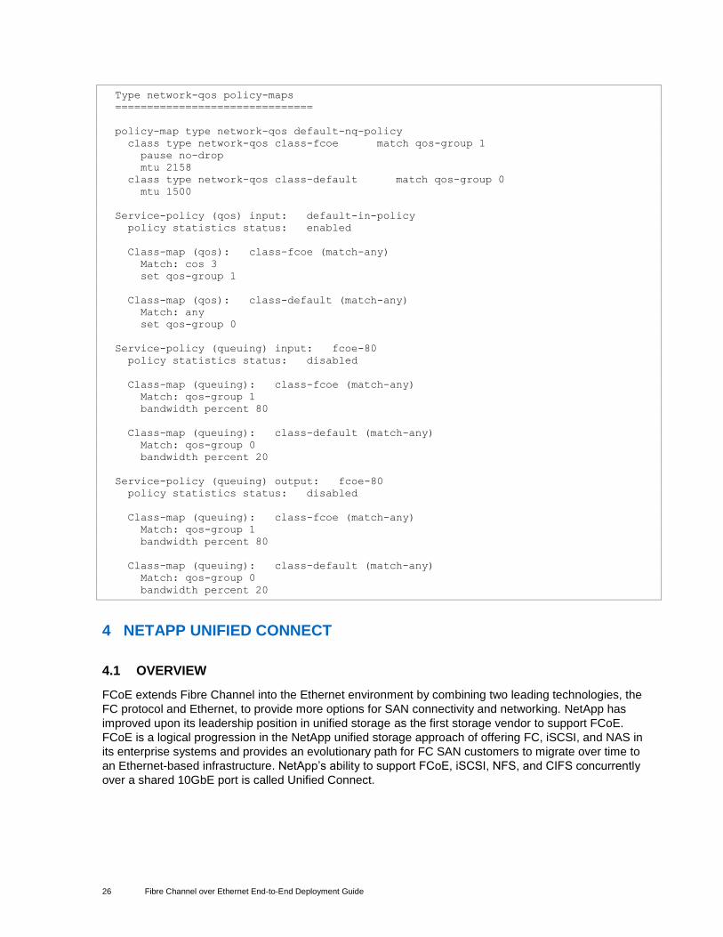
CISCO-N5K-A# show policy-map system
26 Fibre Channel over Ethernet End-to-End Deployment Guide
Type network-qos policy-maps
===============================
policy-map type network-qos default-nq-policy
class type network-qos class-fcoe match qos-group 1
pause no-drop
mtu 2158
class type network-qos class-default match qos-group 0
mtu 1500
Service-policy (qos) input: default-in-policy
policy statistics status: enabled
Class-map (qos): class-fcoe (match-any)
Match: cos 3
set qos-group 1
Class-map (qos): class-default (match-any)
Match: any
set qos-group 0
Service-policy (queuing) input: fcoe-80
policy statistics status: disabled
Class-map (queuing): class-fcoe (match-any)
Match: qos-group 1
bandwidth percent 80
Class-map (queuing): class-default (match-any)
Match: qos-group 0
bandwidth percent 20
Service-policy (queuing) output: fcoe-80
policy statistics status: disabled
Class-map (queuing): class-fcoe (match-any)
Match: qos-group 1
bandwidth percent 80
Class-map (queuing): class-default (match-any)
Match: qos-group 0
bandwidth percent 20
4 NETAPP UNIFIED CONNECT
4.1 OVERVIEW
FCoE extends Fibre Channel into the Ethernet environment by combining two leading technologies, the
FC protocol and Ethernet, to provide more options for SAN connectivity and networking. NetApp has
improved upon its leadership position in unified storage as the first storage vendor to support FCoE.
FCoE is a logical progression in the NetApp unified storage approach of offering FC, iSCSI, and NAS in
its enterprise systems and provides an evolutionary path for FC SAN customers to migrate over time to
an Ethernet-based infrastructure. NetApp’s ability to support FCoE, iSCSI, NFS, and CIFS concurrently
over a shared 10GbE port is called Unified Connect.
27 Fibre Channel over Ethernet End-to-End Deployment Guide
4.2 FCOE TARGET AND UNIFIED CONNECT REQUIREMENTS
Starting with Data ONTAP® 7.3.2, FCoE is available through our Unified Target Adapters (UTAs) in the
Data ONTAP 7.3 family. In Data ONTAP 8.0.1 and later, FCoE and all other Ethernet protocols normally
available from NetApp storage (CIFS, NFS, iSCSI, and so on) are supported concurrently. The FC
protocol license is required for FCoE functionality. For other protocols, the relevant license is required.
When a UTA is installed in a NetApp storage controller running Data ONTAP 8.0.1, a dual-port 10Gb/s
network interface card (NIC) and a 10Gb/s FCoE target adapter are presented for each UTA installed in
the controller. See the sysconfig output in section 4.4 below for an example. This is the same way that a
CNA is presented on the host.
The UTA is supported on all current platforms that have a PCIe expansion slot. See the System
Configuration Guide for details on the number of cards supported on a particular platform.
4.3 HOST AND STORAGE SYSTEM CONFIGURATION
Configuration of the FCoE side of the Unified Target Adapter in Data ONTAP is the same as it is for a
traditional Fibre Channel target adapter. The storage controller determines the appropriate DCB settings
and VLAN to use for FCoE from the upstream FCF with no user involvement needed. See section 3.13
for details on FCoE link configuration.
From that point, igroups can be created with the hosts’ initiator WWPNs, and LUNs can be mapped to the
igroups the same way as with traditional FC. An igroup can even include a mixture of traditional FC and
FCoE initiator WWPNs if the host or cluster has both. Also, a host (FC or FCoE) can connect to a LUN
presented on the NetApp storage controller over both the storage controller’s FC and FCoE ports. These
options can be useful when migrating from a traditional FC environment to an FCoE environment.
See the Fibre Channel and iSCSI Configuration Guide for details and examples of different supported
connectivity options. For explicit instructions on creating LUNs and igroups, please see the Block Access
Management Guide for iSCSI and FC for your version of Data ONTAP.
NetApp also provides a set of software programs and documentation that enable host operating systems
to be connected to NetApp storage systems called host utilities.
The host utilities include the following components:
An installation program that sets required parameters on the host computer and CNA or HBA
Diagnostic programs for displaying important information about the host, CNAs, FCoE and FC switches, and storage systems in the network
Before installing the host utilities, verify that the host utilities version supports the host and storage
system configuration. The NetApp Interoperability Matrix Tool (IMT) lists all supported configurations. For
x86 and x86-64 industry-standard hosts, individual computer models are not listed. Instead, hosts are
qualified based on the CPU architecture. The following configuration items must be verified:
Host CPU architecture
Operating system version, service pack level, and required hotfixes
FC/FCoE switch model and firmware version
Multipathing software
Data ONTAP version
Software such as SnapDrive® for Windows
There are also important notes and warnings for many configurations listed in the IMT that we found
through our certification testing. Please take the time to read these when they apply to your configuration.
They will be called out as a hyperlink in the IMT row of your configuration.
28 Fibre Channel over Ethernet End-to-End Deployment Guide
Specific host and storage system configuration steps can be found in the host utilities Installation and
Administration Guides and the Data ONTAP Block Access Management Guide for iSCSI and FC for your
version of Data ONTAP.
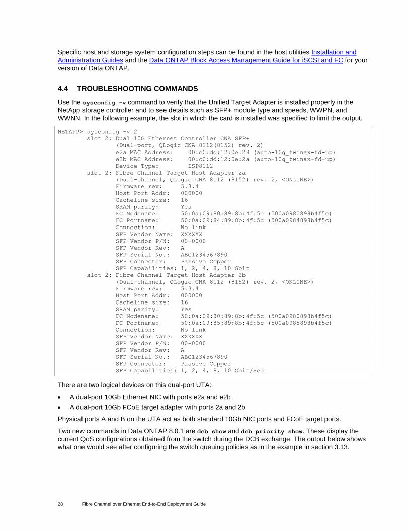
4.4 TROUBLESHOOTING COMMANDS
Use the sysconfig -v command to verify that the Unified Target Adapter is installed properly in the
NetApp storage controller and to see details such as SFP+ module type and speeds, WWPN, and
WWNN. In the following example, the slot in which the card is installed was specified to limit the output.
NETAPP> sysconfig -v 2
slot 2: Dual 10G Ethernet Controller CNA SFP+
(Dual-port, QLogic CNA 8112(8152) rev. 2)
e2a MAC Address: 00:c0:dd:12:0e:28 (auto-10g_twinax-fd-up)
e2b MAC Address: 00:c0:dd:12:0e:2a (auto-10g_twinax-fd-up)
Device Type: ISP8112
slot 2: Fibre Channel Target Host Adapter 2a
(Dual-channel, QLogic CNA 8112 (8152) rev. 2, <ONLINE>)
Firmware rev: 5.3.4
Host Port Addr: 000000
Cacheline size: 16
SRAM parity: Yes
FC Nodename: 50:0a:09:80:89:8b:4f:5c (500a0980898b4f5c)
FC Portname: 50:0a:09:84:89:8b:4f:5c (500a0984898b4f5c)
Connection: No link
SFP Vendor Name: XXXXXX
SFP Vendor P/N: 00-0000
SFP Vendor Rev: A
SFP Serial No.: ABC1234567890
SFP Connector: Passive Copper
SFP Capabilities: 1, 2, 4, 8, 10 Gbit
slot 2: Fibre Channel Target Host Adapter 2b
(Dual-channel, QLogic CNA 8112 (8152) rev. 2, <ONLINE>)
Firmware rev: 5.3.4
Host Port Addr: 000000
Cacheline size: 16
SRAM parity: Yes
FC Nodename: 50:0a:09:80:89:8b:4f:5c (500a0980898b4f5c)
FC Portname: 50:0a:09:85:89:8b:4f:5c (500a0985898b4f5c)
Connection: No link
SFP Vendor Name: XXXXXX
SFP Vendor P/N: 00-0000
SFP Vendor Rev: A
SFP Serial No.: ABC1234567890
SFP Connector: Passive Copper
SFP Capabilities: 1, 2, 4, 8, 10 Gbit/Sec
There are two logical devices on this dual-port UTA:
A dual-port 10Gb Ethernet NIC with ports e2a and e2b
A dual-port 10Gb FCoE target adapter with ports 2a and 2b
Physical ports A and B on the UTA act as both standard 10Gb NIC ports and FCoE target ports.
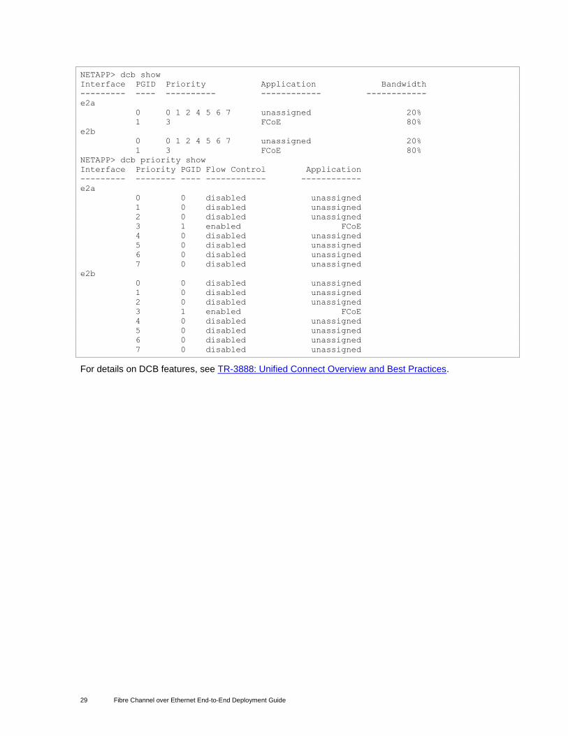
Two new commands in Data ONTAP 8.0.1 are dcb show and dcb priority show. These display the
current QoS configurations obtained from the switch during the DCB exchange. The output below shows
what one would see after configuring the switch queuing policies as in the example in section 3.13.
29 Fibre Channel over Ethernet End-to-End Deployment Guide
NETAPP> dcb show
Interface PGID Priority Application Bandwidth
--------- ---- ---------- ------------ ------------
e2a
0 0 1 2 4 5 6 7 unassigned 20%
1 3 FCoE 80%
e2b
0 0 1 2 4 5 6 7 unassigned 20%
1 3 FCoE 80%
NETAPP> dcb priority show
Interface Priority PGID Flow Control Application
--------- -------- ---- ------------ ------------
e2a
0 0 disabled unassigned
1 0 disabled unassigned
2 0 disabled unassigned
3 1 enabled FCoE
4 0 disabled unassigned
5 0 disabled unassigned
6 0 disabled unassigned
7 0 disabled unassigned
e2b
0 0 disabled unassigned
1 0 disabled unassigned
2 0 disabled unassigned
3 1 enabled FCoE
4 0 disabled unassigned
5 0 disabled unassigned
6 0 disabled unassigned
7 0 disabled unassigned
For details on DCB features, see TR-3888: Unified Connect Overview and Best Practices.
30 Fibre Channel over Ethernet End-to-End Deployment Guide
NetApp provides no representations or warranties regarding the accuracy, reliability or serviceability of any information or recommendations provided in this publication, or with respect to any results that may be obtained by the use of the information or observance of any recommendations provided herein. The information in this document is distributed AS IS, and the use of this information or the implementation of any recommendations or techniques herein is a customer’s responsibility and depends on the customer’s ability to evaluate and integrate them into the customer’s operational environment. This document and the information contained herein may be used solely in connection with the NetApp products discussed in this document.
© 2011 NetApp, Inc. All rights reserved. No portions of this document may be reproduced without prior written consent of NetApp, Inc. Specifications are subject to change without notice. NetApp, the NetApp logo, Go further, faster are trademarks or registered trademarks of NetApp, Inc. in the United States and/or other countries. All other brands or products are trademarks or registered trademarks of their respective holders and should be treated as such. TR-3800-0711


