163
Dual-Band Wireless AC Access Point User Manual Models WAC720 and WAC730 March 2018 202-11624-06 350 E. Plumeria Drive San Jose, CA 95134 USA
Dual-Band Wireless ACAccess PointUser Manual
Models WAC720 and WAC730
March 2018202-11624-06
350 E. Plumeria DriveSan Jose, CA 95134USA
SupportThank you for purchasing this NETGEAR product.You can visit www.netgear.com/support to register yourproduct, get help, access the latest downloads and user manuals, and join our community. We recommend thatyou use only official NETGEAR support resources.
ConformityFor the current EU Declaration of Conformity, visit http://kb.netgear.com/app/answers/detail/a_id/11621.
ComplianceFor regulatory compliance information, visit http://www.netgear.com/about/regulatory.
See the regulatory compliance document before connecting the power supply.
Trademarks© NETGEAR, Inc., NETGEAR, and the NETGEAR Logo are trademarks of NETGEAR, Inc. Any non-NETGEARtrademarks are used for reference purposes only.
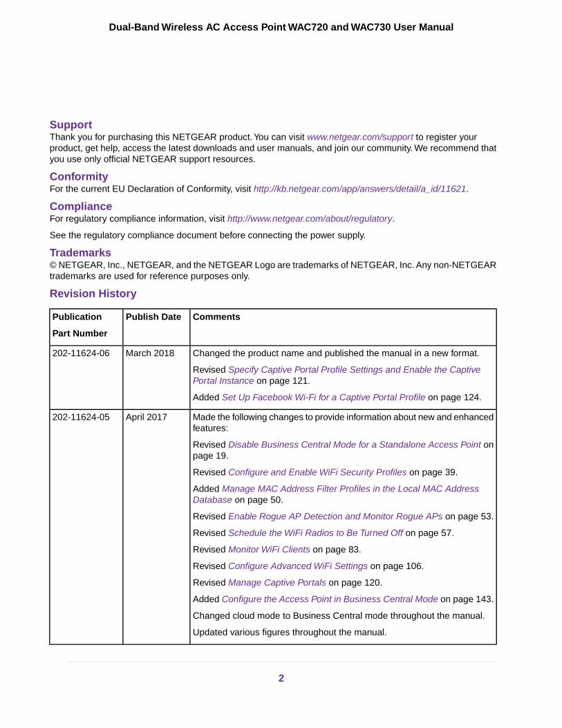
Revision History
CommentsPublish DatePublication
Part Number
Changed the product name and published the manual in a new format.March 2018202-11624-06
Revised Specify Captive Portal Profile Settings and Enable the CaptivePortal Instance on page 121.
Added Set Up Facebook Wi-Fi for a Captive Portal Profile on page 124.
Made the following changes to provide information about new and enhancedfeatures:
April 2017202-11624-05
Revised Disable Business Central Mode for a Standalone Access Point onpage 19.
Revised Configure and Enable WiFi Security Profiles on page 39.
Added Manage MAC Address Filter Profiles in the Local MAC AddressDatabase on page 50.
Revised Enable Rogue AP Detection and Monitor Rogue APs on page 53.
Revised Schedule the WiFi Radios to Be Turned Off on page 57.
Revised Monitor WiFi Clients on page 83.
Revised Configure Advanced WiFi Settings on page 106.
Revised Manage Captive Portals on page 120.
Added Configure the Access Point in Business Central Mode on page 143.
Changed cloud mode to Business Central mode throughout the manual.
Updated various figures throughout the manual.
2
Dual-Band Wireless AC Access Point WAC720 and WAC730 User Manual

CommentsPublish DatePublication
Part Number
Revised Mount the Access Point on page 30 to show the changes to theaccess point mounting bracket.
March 2016202-11624-04
Changed firmware version 3.5.4.0 to version 3.5.6.0 (see Log In to theAccess Point on page 16 and Disable Business Central Mode for aStandalone Access Point on page 19).
Major revision with the following major changes:March 2016202-11624-03
Revised Log In to the Access Point on page 16.
Added Disable Business Central Mode for a Standalone Access Point onpage 19.
Added View Dashboard Information on page 80.
Revised Configure and Enable WiFi Security Profiles on page 39.
Added Configure Load Balancing on page 118.
Revised Set Up, Manage, and Monitor Ensembles on page 87.
Revised Manage Captive Portals on page 120.
Removed the legacy 802.1x security option (RADIUS security option).
Removed the WPA and WPA-PSK (TKIP) security options.
In addition, made many minor changes plus the following nontechnicalchanges:
Increased the quality of all screen shots.
Replaced many screen shots.
Converted all procedures to standalone procedures.
Changed the name of the manual from Reference Manual to User Manual.
Revised Configure WiFi Bridging on page 132.February 2016202-11624-02
Revised Mount the Access Point on page 30.December2015
202-11624-01
First publication.October 2015202-11607-01
3
Dual-Band Wireless AC Access Point WAC720 and WAC730 User Manual
Contents
Chapter 1 Introduction and Hardware Overview
Unpack Your Access Point.....................................................................................9Top Panel...............................................................................................................9Rear Panel...........................................................................................................10Access Point Label...............................................................................................11
Chapter 2 Initial Setup
What You Need Before You Begin........................................................................13System Requirements.....................................................................................13WiFi Equipment Placement and Range Guidelines........................................13Ethernet Cabling Requirements......................................................................14LAN Configuration Requirements....................................................................14Hardware Requirements for Computers on Your LAN.....................................14Operating Frequency Guidelines.....................................................................14Requirements for Entering IP Addresses........................................................14
IPv4............................................................................................................14IPv6............................................................................................................15
Install and Configure the Access Point................................................................15Connect the Access Point to a Computer............................................................15Log In to the Access Point...................................................................................16
Log In to the Access Point When It Is Directly Connected to Your Computer...17Log In to the Access Point When It Is Connected to a Network With a DHCPServer..............................................................................................................18Local Browser Interface...................................................................................18
Disable Business Central Mode for a Standalone Access Point..........................19Configure Basic General System Settings...........................................................20Configure Time Settings.......................................................................................22Configure the IPv4 Settings.................................................................................23Configure the Basic WiFi Settings........................................................................24
Configure 802.11bg/ng/bgn WiFi Settings.......................................................24Configure 802.11a/a-na-ac WiFi Settings.......................................................27
Test Basic WiFi Connectivity................................................................................29Mount the Access Point.......................................................................................30
Package Content of the Ceiling and Wall Installation Kit.................................30Mount the Access Point to a Drop Ceiling.......................................................30Mount the Access Point to a Wall....................................................................33
Chapter 3 Configure the WiFi Features and Security
WiFi Data Security Options..................................................................................37WiFi Security Profiles...........................................................................................38
Configure and Enable WiFi Security Profiles..................................................39About WPA2-PSK and WPA-PSK & WPA2-PSK.............................................46
4

About WPA2 With RADIUS and WPA & WPA2 With RADIUS.........................47Change the QoS Policy for a WiFi Security Profile..........................................47
Configure RADIUS Server Settings.....................................................................48Manage MAC Address Filter Profiles in the Local MAC Address Database........50
Add a MAC Address Filter Profile....................................................................51Modify a MAC Address Filter Profile...............................................................52Delete a MAC Address Filter Profile................................................................53
Enable Rogue AP Detection and Monitor Rogue APs.........................................53Enable Rogue AP Detection............................................................................54Monitor Rogue APs.........................................................................................55Monitor Knows APs.........................................................................................56
Schedule the WiFi Radios to Be Turned Off.........................................................57Configure Basic WiFi Quality of Service..............................................................59
Chapter 4 Manage and Monitor the Access Point
Enable Remote Management..............................................................................62SNMP Management........................................................................................62Secure Shell and Telnet Management.............................................................63Manage the Access Point over a Telnet Connection.......................................64
Upgrade the Access Point Firmware....................................................................65Upgrade the Firmware Over a Web Browser...................................................65Upgrade the Firmware Over a TFTP Server...................................................66
Manage the Configuration File or Reset to Factory Defaults...............................67Save the Configuration....................................................................................68Restore the Configuration...............................................................................68Restore the Access Point to the Factory Default Settings...............................69
Use the Local Browser Interface to Restore Factory Default Settings........70Use the Reset Button to Restore Factory Default Settings.........................70
Reboot the Access Point Without Restoring the Default Configuration...........71Change the Administrator Password....................................................................72Manage User Accounts........................................................................................73
Add a New User Account................................................................................73Change the Name for a User Account............................................................74Change the Privilege for a User Account........................................................75Reset the Password for a User Account..........................................................75Delete a User Account....................................................................................76
Enable the Syslog Server....................................................................................76Monitor the Access Point.....................................................................................77
View System Information.................................................................................78View Dashboard Information...........................................................................80
View the Standalone Dashboard................................................................80View the Ensemble Dashboard..................................................................81
Monitor WiFi Clients........................................................................................83View the Activity Logs..........................................................................................85View the Traffic Statistics......................................................................................86Set Up, Manage, and Monitor Ensembles...........................................................87
Configure Enable Ensemble Mode..................................................................88Manage an Ensemble.....................................................................................88
5
Dual-Band Wireless AC Access Point WAC720 and WAC730 User Manual
Specify an Ensemble Management IP Address.........................................89Configure Ensemble Security With a Passphrase......................................89Specify an Ensemble’s Channel Assignment Settings...............................90Manage Automatic Channel Assignment for an Ensemble........................91Upgrade the Firmware of Ensemble Members From a Downloaded FirmwareFile..............................................................................................................93Upgrade the Firmware of Ensemble Members Over a TFTP Server..........95
Monitor an Ensemble......................................................................................96Monitor the Status of the Ensemble...........................................................96Monitor the Devices Connected to the Ensemble.......................................97Monitor the Access Points and Networks Neighboring the Ensemble........98
Chapter 5 Configure Advanced Network and WiFi Features
Configure IPv6 Settings.....................................................................................101Configure Spanning Tree Protocol, 802.1Q VLAN, and Link Layer DiscoveryProtocol..............................................................................................................102
Configure STP and VLANs............................................................................102Configure Ethernet LLDP..............................................................................104
Configure Bonjour..............................................................................................105Configure Advanced WiFi Settings....................................................................106Configure Advanced Quality of Service Settings...............................................109Configure and Manage Quality of Service Policies............................................112
Configure a New QoS Policy.........................................................................112Modify a QoS Policy......................................................................................117Delete a QoS Policy......................................................................................118
Configure Load Balancing..................................................................................118Manage Captive Portals.....................................................................................120Enable the Access Point to Register With Facebook.........................................121Specify Captive Portal Profile Settings and Enable the Captive Portal Instance.121Set Up Facebook Wi-Fi for a Captive Portal Profile...........................................124Add User Accounts to the Local Database for Captive Portal Access...............126Upload a Custom Logo......................................................................................128Configure a Default or Custom Captive Portal Splash Page..............................129Enable the Global Captive Portal Mode.............................................................131Configure WiFi Bridging.....................................................................................132
Point-to-Point Bridge and Point-to-Multipoint Bridge.....................................132Configure a WiFi Bridge................................................................................133
Chapter 6 Troubleshooting
Troubleshoot the Basic Functions......................................................................137Verify the Correct Sequence of Events at Startup.........................................137No LEDs Are Lit on the Access Point............................................................137The Active LED or the LAN LED Is Not Lit....................................................138The WLAN LED Does Not Light....................................................................138
You Cannot Access the Internet or the LAN From a WiFi Computer.................138You Cannot Configure the Access Point From a Browser..................................139When You Enter a URL or IP Address a Time-Out Error Occurs.......................140Troubleshoot a TCP/IP Network Using the Ping Utility.......................................140
6
Dual-Band Wireless AC Access Point WAC720 and WAC730 User Manual

Test the LAN Path to Your Access Point........................................................140Test the Path from Your Computer to a Remote Device................................141
Problems With Date and Time...........................................................................141Use the Packet Capture Tool..............................................................................142
Appendix A Configure the Access Point in Business Central Mode
Enable Business Central Mode..........................................................................144Configure the IP and 802.1Q VLAN Settings in Business Central Mode...........145Reboot the Access Point in Business Central Mode..........................................146Reset the Access Point in Business Central Mode to Factory Default Settings..147Upgrade Access Point Firmware in Business Central Mode..............................148Configure MAC Authentication in Business Central Mode.................................148
Add a MAC Address Filter Profile on an Access Point in Business CentralMode.............................................................................................................149Assign a MAC Address Filter Profile on an Access Point in Business CentralMode.............................................................................................................151Modify a MAC Address Filter Profile on an Access Point in Business CentralMode.............................................................................................................153Delete a MAC Address Filter Profile on an Access Point in Business CentralMode.............................................................................................................154
Monitor the Access Point in Business Central Mode.........................................154View the Activity Logs of an Access Point in Business Central Mode...........155View Basic Information About the Access Point In Business Central Mode...156
Appendix B Supplemental Information
Technical Specifications.....................................................................................158Factory Default Settings.....................................................................................161
7
Dual-Band Wireless AC Access Point WAC720 and WAC730 User Manual

1Introduction and Hardware Overview
This user manual describes how you can manage the NETGEAR Dual-Band Wireless AC Access Point modelsWAC720 and WAC730 by using the local browser–based management interface, in this manual referred to asthe local browser interface.
The essential differences between the two models are the maximum theoretical WiFi throughput and the numberof supported optional dual-band antennas:
• Model WAC720. This model can support two optional dual-band antennas. The maximum theoretical WiFithroughput is 300 Mbps in the 2.4 GHz band and 867 Mbps in the 5 GHz band
• Model WAC730.This model can support three optional dual-band antennas.The maximum theoretical WiFithroughput is 450 Mbps in the 2.4 GHz band and 1300 Mbps in the 5 GHz band
This chapter includes the following sections:
• Unpack Your Access Point• Top Panel• Rear Panel• Access Point Label
For more information about the topics covered in this manual, visit the support website atnetgear.com/support.
Note
Firmware updates with new features and bug fixes are made available from time to time atdownloadcenter.netgear.com. Some products can regularly check the site and downloadnew firmware, or you can check for and download new firmware manually. If the features orbehavior of your product does not match what is described in this guide, you might need toupdate your firmware.
Note
In this manual, WiFi and wireless are interchangeable terms.Note
8

Unpack Your Access Point
Your package contains the following items:
• ProSAFE Dual-Band Wireless AC Access Point
• Straight-through Category 5 Ethernet cable
• Ceiling and wall installation kit
• Installation guide
Contact your reseller or customer support in your area if any parts are missing or damaged.
Visit the NETGEAR website at support.netgear.com/general/contact/default.aspx for the telephone numberof customer support in your area.
Top Panel
The following figure shows the LEDs on the top panel.
Figure 1. Top panel
The following table describes the LEDs on the top panel.
Introduction and Hardware Overview
9
Dual-Band Wireless AC Access Point WAC720 and WAC730 User Manual

Table 1.Top panel LEDs
DescriptionLEDItem
Power is off.OffPower/Test1
Power is on.On (green)
A self-test is running or firmware is being loaded. Duringstartup, the LED is first steady amber, then goes off, andthen blinks green before turning steady green after about45 seconds. If after one minute the LED remains amberor continues to blink green, it indicates a system fault.
Amber, then blinkinggreen
No Ethernet traffic is detected, or no link is detected.OffActive2
Ethernet traffic is detected.On or blinking (green)
A 10 Mbps or no link is detected on LAN port.OffLAN3
A 100 Mbps link is detected on LAN port.Amber
A 1000 Mbps link is detected on LAN port.Green
The WiFi 802.11b/g/n (2.4 GHz) LAN is not ready, or noWiFi activity is detected.
Off2.4 GHzWLAN
4
The WiFi 802.11b/g/n (2.4 GHz) LAN is ready, or WiFiactivity is detected.
On or blinking (green)
The WiFi 802.11n/a (5 GHz) LAN is not ready, or no WiFiactivity is detected.
Off5 GHzWLAN
5
The WiFi 802.11n/a (5 GHz) LAN is ready, or WiFi activityis detected.
On or blinking (green)
Rear Panel
Figure 2. Rear panel
Introduction and Hardware Overview
10
Dual-Band Wireless AC Access Point WAC720 and WAC730 User Manual

The rear panel components of the access point, from left to right, are described in the following list:
1. Cable security lock receptacle for an optional lock.
2. Console port for connecting to an optional console terminal. The port provides an RJ-45 connector andsupports the following settings: 115200 K default baud rate, 8 data bits, no (N) parity bit, and one (1)stop bit.
3. Factory default Reset button. Using a sharp object, press and hold this button for about five secondsto reset the access point to factory defaults settings. All configuration settings are lost, and the defaultpassword is restored. For more information, see Restore the Access Point to the Factory Default Settingson page 69.
4. 10/100/1000BASE-T Gigabit Ethernet (RJ-45) port with Auto Uplink (Auto MDI-X) and support forIEEE 802.3af Power over Ethernet (PoE) for connection to a switch or router that can provide PoE.
5. Power socket for an optional 12 VDC, 2.5A power adapter.
The WAC720 access point can support up to two optional 2.4 GHz/5 GHz dual-bandantennas.The WAC730 access point can support up to three optional 2.4 GHz/5 GHzdual-band antennas.
Note
Access Point Label
The access point label on the bottom of the access point’s enclosure displays factory default settings,regulatory compliance, and other information.
Figure 3. Label model WAC720
Figure 4. Label model WAC730
Introduction and Hardware Overview
11
Dual-Band Wireless AC Access Point WAC720 and WAC730 User Manual
2Initial Setup
This chapter includes the following sections:
• What You Need Before You Begin• Install and Configure the Access Point• Connect the Access Point to a Computer• Log In to the Access Point• Disable Business Central Mode for a Standalone Access Point• Configure Basic General System Settings• Configure Time Settings• Configure the IPv4 Settings• Configure the Basic WiFi Settings• Test Basic WiFi Connectivity• Mount the Access Point
12

What You Need Before You Begin
You must consider the following guidelines and requirements before you can set up your access point.
System RequirementsBefore installing the access point, make sure that your system includes the following:
• A 10/100/1000 Mbps local area network device such as a hub or switch
• The Category 5 UTP straight-through Ethernet cable with RJ-45 connector included in the package, orone like it
• A PoE switch or a 12V, 2.5 A, DC power source
• A web browser for configuration
• At least one computer with the TCP/IP protocol installed
• 802.11bg/ng/bgn-compliant or 802.11a/a-na-ac-compliant devices
WiFi Equipment Placement and Range GuidelinesThe range of your WiFi connection can vary significantly based on the location of the access point. Thelatency, data throughput performance, and power consumption of WiFi devices also vary depending on yourconfiguration choices.
Failure to follow these guidelines can result in significant performance degradationor inability to connect over WiFi to the access point. For complete performancespecifications, see Supplemental Information on page 157.
Note
Before you position and mount the access point at its permanent position, first configurethe access point and test the computers on your LAN for WiFi connectivity as describedin this chapter.
Note
For best results, place your access point according to the following general guidelines:
• Near the center of the area in which the WiFi devices will operate.
• In an elevated location such as a high shelf where the WiFi devices are in a line-of-sight (even if throughwalls).
• Away from sources of interference, such as computers, microwaves ovens, and 2.4 GHz cordlessphones.
• Away from large metal surfaces or water.
• Placing an external antenna in a vertical position provides best side-to-side coverage. Placing an externalantenna in a horizontal position provides best up-and-down coverage. (An external antenna does notcome standard with the access point.)
Initial Setup
13
Dual-Band Wireless AC Access Point WAC720 and WAC730 User Manual
If you are using multiple access points, it is better if adjacent access points use different radio frequencychannels to reduce interference. The recommended channel spacing between adjacent access points isfive channels (for example, use Channels 1 and 6, or 6 and 11, or 1 and 11).
The time it takes to establish a WiFi connection can vary depending on both your security settings andplacement.
Ethernet Cabling RequirementsThe access point connects to your LAN using twisted-pair Category 5 Ethernet cable with RJ-45 connectors.
LAN Configuration RequirementsFor the initial configuration of your access point, you must connect a computer to the access point.
Hardware Requirements for Computers on Your LANTo connect to the access point on your network, your WiFi device must support 802.11b, 802.11g, 802.11n,802.11a, or 802.11ac. If your computer does not include an internal WiFi adapter, we recommend using theNETGEAR A6210 WiFi USB Adapter.
Operating Frequency GuidelinesYou do not need to change the operating frequency (channel) unless you notice interference problems oryou place the access point near another access point. If you do change the operating frequency, observethe following guidelines:
• Access points use a fixed channel.You can select a channel that provides the least interference andbest performance. In the United States and Canada, 11 channels are available.
• If you use multiple access points, it is better if adjacent access points use different channels to reduceinterference. The recommended channel spacing between adjacent access points is five channels (forexample, use Channels 1 and 6, or 6 and 11).
• In infrastructure mode (which is the default mode for the access point), WiFi stations normally scan allchannels, looking for a access point. If more than one access point can be used, the one with thestrongest signal is used. This is possible only if the access points use the same SSID.
Requirements for Entering IP AddressesIP addresses assigned to the access points must follow the following requirements for IPv4 and IPv6addresses.
IPv4
The fourth octet of an IP address must be between 0 and 255 (both inclusive). This requirement applies toany IP address that you enter on the access point’s local browser interface.
Initial Setup
14
Dual-Band Wireless AC Access Point WAC720 and WAC730 User Manual
IPv6
IPv6 addresses are denoted by eight groups of hexadecimal quartets that are separated by colons. Anyfour-digit group of zeroes within an IPv6 address can be reduced to a single zero or altogether omitted.
The following errors invalidate an IPv6 address:
• More than eight groups of hexadecimal quartets
• More than four hexadecimal characters in a quartet
• More than two colons in a row
Install and Configure the Access Point
Install and configure your access point in the order of the following sections:
1. Connect the Access Point to a Computer on page 15
2. Log In to the Access Point on page 16
3. Disable Business Central Mode for a Standalone Access Point on page 19
4. Configure Basic General System Settings on page 20
5. Configure Time Settings on page 22
6. Configure the IPv4 Settings on page 23
7. Configure the Basic WiFi Settings on page 24
Before installing the access point, make sure that your Ethernet network functions. After you connectthe access point to the Ethernet network, computers that support 802.11b/g/a/n/ac are able tocommunicate with the Ethernet network.
For this to work correctly, verify that you meet all the system requirements, shown in What You NeedBefore You Begin on page 13.
Connect the Access Point to a Computer
Before you place the access point in an elevated position that is difficult to reach, first setup and test the access point to verify WiFi network connectivity.
Tip
To set up the access point:
1. Unpack the box and verify the contents.
2. Prepare a computer with an Ethernet adapter.
If this computer is already part of your network, record its TCP/IP configuration settings. Configure thecomputer with a static IP address of 192.168.0.210 and 255.255.255.0 as the subnet mask.
3. Connect an Ethernet cable from the access point to the computer.
4. Securely insert the other end of the cable into the access point’s Ethernet port.
5. Turn on your computer.
Initial Setup
15
Dual-Band Wireless AC Access Point WAC720 and WAC730 User Manual

6. Connect the access point to a PoE switch or power adapter.
The access point supports Power over Ethernet (PoE) with power redundancy. If you areusing a switch that provides PoE, you do not need to use a power adapter to power theaccess point. Using PoE can be especially convenient when the access point is installedin a high location far away from a power outlet.
Tip
7. Verify that the LEDs functions as indicated in the following table:
DescriptionLED
Power/Test LED. The Power/Test LED blinks when the access point is first turned on. (To beexact, during startup, the LED is first steady amber, then goes off, and then blinks green.) Afterabout 45 seconds, the LED stays lit (steady green). If after one minute the Power/Test LED isnot lit or is still blinking, check the connections and see if the power outlet is controlled by awall switch that is turned off.
Active LED. The Active LED is lit or blinks green when Ethernet traffic is detected.
LAN LED. The LAN LED indicates the LAN speed for LAN port 1: green for 1000 Mbps, amberfor 100 Mbps, and no light for 10 Mbps. If the LAN LED is not lit, make sure that the Ethernetcable is securely attached at both ends.
2.4 GHz WLAN LED.The 2.4 GHz WLAN LED is lit or blinks green when the WiFi LAN (WLAN)is ready.
5 GHz WLAN LED. The 5 GHz WLAN LED is lit or blinks green when the WiFi LAN (WLAN)is ready.
Log In to the Access Point
The default IP address of your access point is 192.168.0.100.
By default, the access point functions as a DHCP client. If the access point is installed in a network thatincludes a DHCP server, the IP address of the access point is issued by the DHCP server.You can find theIP address of the access point by accessing the DHCP server or by using an IP address scanner utility.(Free IP address scanner utilities are available online.)
If you must configure the access point with a static IPv4 address, see the steps in Log In to the Access PointWhen It Is Directly Connected to Your Computer on page 17 and Configure the IPv4 Settings on page 23.
Initial Setup
16
Dual-Band Wireless AC Access Point WAC720 and WAC730 User Manual

When the access point runs firmware version 3.5.6.0 or a later version, by default, theaccess point is enabled for the cloud (that is, Business Central mode is enabled) andoperates with a limited local browser interface (only the Configuration and Monitoringmenu tabs display).
Note
Log In to the Access Point When It Is Directly Connected toYour ComputerTo log in to the access point when it is directly connected to your computer:
1. Change the IP address of your computer to an IP address in the 192.168.0.x subnet, which is the subnetin which the access point’s default IP address is located.
2. For example, change the computer’s IP address to 192.168.0.210.
3. Connect your computer to the access point with an Ethernet cable.
4. Open a web browser on your computer.
5. In the address bar, enter http://192.168.0.100.
192.168.0.100 is the default IP address of the access point.
6. Enter the user name and password.
The user name is admin. The default password is password. The user name and password arecase-sensitive.
7. Click the Login button.
The web browser displays the General page under the Configuration tab. If you are using the accesspoint as a standalone access point or as an access point with a wireless controller, you must disableBusiness Central mode (see Disable Business Central Mode for a Standalone Access Point on page19).
After you disable Business Central mode and you log in to the access point, the web browser displaysthe Dashboard page under the Monitoring tab of the main menu. For more information, see ViewDashboard Information on page 80.
Initial Setup
17
Dual-Band Wireless AC Access Point WAC720 and WAC730 User Manual
Log In to the Access Point When It Is Connected to a NetworkWith a DHCP ServerTo log in to the access point when it is connected to a network with a DHCP server.
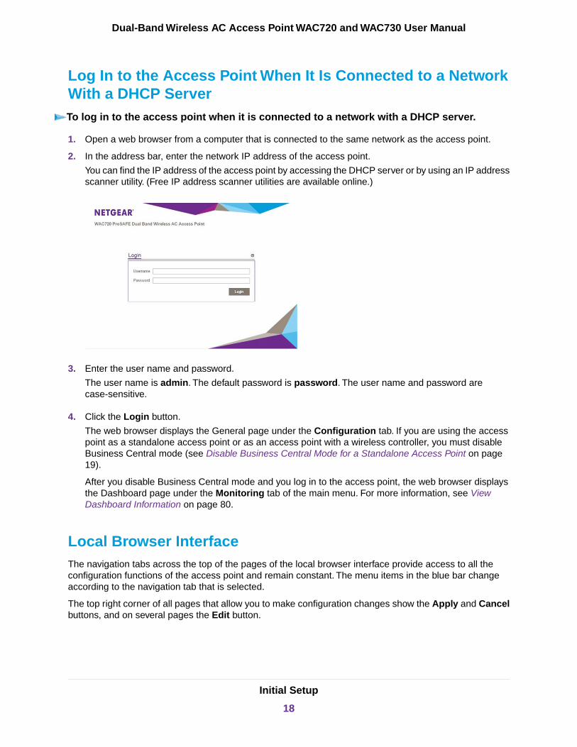
1. Open a web browser from a computer that is connected to the same network as the access point.
2. In the address bar, enter the network IP address of the access point.
You can find the IP address of the access point by accessing the DHCP server or by using an IP addressscanner utility. (Free IP address scanner utilities are available online.)
3. Enter the user name and password.
The user name is admin. The default password is password. The user name and password arecase-sensitive.
4. Click the Login button.
The web browser displays the General page under the Configuration tab. If you are using the accesspoint as a standalone access point or as an access point with a wireless controller, you must disableBusiness Central mode (see Disable Business Central Mode for a Standalone Access Point on page19).
After you disable Business Central mode and you log in to the access point, the web browser displaysthe Dashboard page under the Monitoring tab of the main menu. For more information, see ViewDashboard Information on page 80.
Local Browser InterfaceThe navigation tabs across the top of the pages of the local browser interface provide access to all theconfiguration functions of the access point and remain constant. The menu items in the blue bar changeaccording to the navigation tab that is selected.
The top right corner of all pages that allow you to make configuration changes show the Apply and Cancelbuttons, and on several pages the Edit button.
Initial Setup
18
Dual-Band Wireless AC Access Point WAC720 and WAC730 User Manual

These buttons provide the following functions:
• Edit. Allows you to edit the existing configuration.
• Cancel. Cancels all configuration changes that you made on the page.
• Apply. Saves and applies all configuration changes that you made on the page.
Disable Business Central Mode for a Standalone AccessPoint
When the access point runs firmware version 3.5.6.0 or a later version, by default, Business Central mode(also referred to as cloud mode) is enabled for the access point and the local browser interface is a restrictedinterface that shows only the Configuration and Monitoring menu tabs with limited configuration options.
If you are using the access point as a standalone access point or as an access point with a wireless controller,you must disable Business Central mode.
For information about configuring the access point in Business Central mode, seeConfigure the Access Point in Business Central Mode on page 143.
To disable Business Central mode:
1. Open a web browser from a computer that is connected to the same network as the access point or tothe access point directly through an Ethernet cable.
For more information, see Log In to the Access Point on page 16.
2. In the address bar, enter the IP address of the access point.
A login window opens.
3. Enter the user name and password.
The user name is admin. The default password is password. The user name and password arecase-sensitive.
Initial Setup
19
Dual-Band Wireless AC Access Point WAC720 and WAC730 User Manual

4. Select the Business Central Enabled No radio button.
5. Click the Apply button.
The access point restarts with factory default settings but retains its IP configuration and managementVLAN.
The access point is now ready for standalone operation with a full local browser interface.
Configure Basic General System Settings
To configure basic system settings:
1. Open a web browser from a computer that is connected to the same network as the access point or tothe access point directly through an Ethernet cable.
For more information, see Log In to the Access Point on page 16.
2. In the address bar, enter the IP address of the access point.
A login window opens.
3. Enter the user name and password.
The user name is admin. The default password is password. The user name and password arecase-sensitive.
4. Select Configuration > System > Basic > General.
Initial Setup
20
Dual-Band Wireless AC Access Point WAC720 and WAC730 User Manual
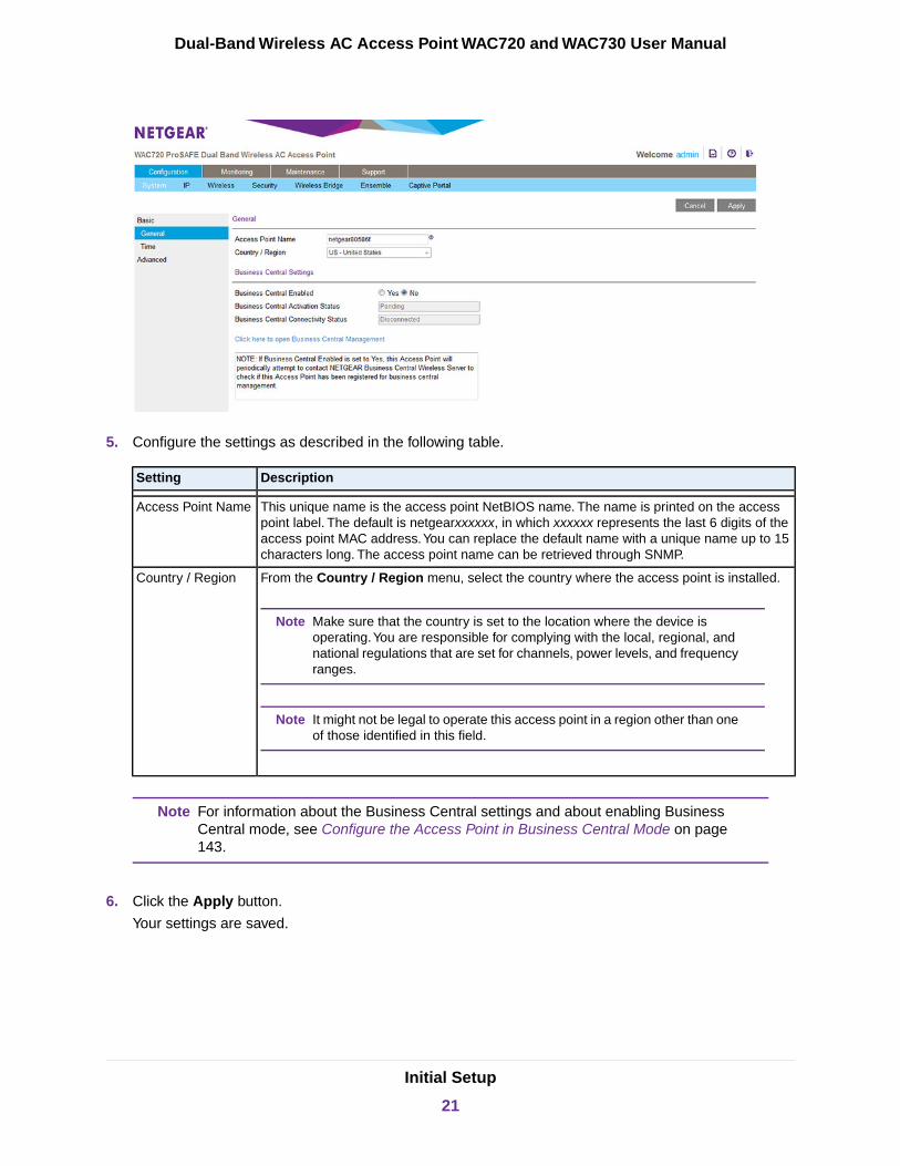
5. Configure the settings as described in the following table.
DescriptionSetting
This unique name is the access point NetBIOS name. The name is printed on the accesspoint label. The default is netgearxxxxxx, in which xxxxxx represents the last 6 digits of theaccess point MAC address.You can replace the default name with a unique name up to 15characters long. The access point name can be retrieved through SNMP.
Access Point Name
From the Country / Region menu, select the country where the access point is installed.
Make sure that the country is set to the location where the device isoperating.You are responsible for complying with the local, regional, andnational regulations that are set for channels, power levels, and frequencyranges.
Note
It might not be legal to operate this access point in a region other than oneof those identified in this field.
Note
Country / Region
For information about the Business Central settings and about enabling BusinessCentral mode, see Configure the Access Point in Business Central Mode on page143.
Note
6. Click the Apply button.
Your settings are saved.
Initial Setup
21
Dual-Band Wireless AC Access Point WAC720 and WAC730 User Manual

Configure Time Settings
To configure time settings:
1. Open a web browser from a computer that is connected to the same network as the access point or tothe access point directly through an Ethernet cable.
For more information, see Log In to the Access Point on page 16.
2. In the address bar, enter the IP address of the access point.
A login window opens.
3. Enter the user name and password.
The user name is admin. The default password is password. The user name and password arecase-sensitive.
4. Select Configuration > System > Basic > Time.
5. Configure the settings as described in the following table.
DescriptionSetting
Select the time zone to match your location.Time Zone
This is a nonconfigurable field that displays the current date and time.Current Time
Enable the Network Time Protocol (NTP) client to synchronize the time of the accesspoint with an NTP server. By default the Enable radio button is selected.
NTP Client
Select this check box if you want to use a custom NTP server.
You need an Internet connection to use an NTP server that is not on your local network.
Use Custom NTP Server
Enter the host name or IP address of the custom NTP server.The default is time-b.netgear.com.
If you use a host name, make sure that you configured a DNSserver.
Hostname / IP Address
6. Click the Apply button.
Your settings are saved.
Initial Setup
22
Dual-Band Wireless AC Access Point WAC720 and WAC730 User Manual
Configure the IPv4 Settings
For information about how to configure the IPv6 settings, see Configure IPv6 Settingson page 101.
Note
WARNING:If you enable the DHCP client, the IP address of the access point changeswhen you click the Apply button, causing you to lose your connection to theaccess point.You must use the new IP address to reconnect to the accesspoint.
If you enable the DHCP client on the access point, you can discover the new IP addressof the access point by accessing the DHCP server on your LAN, or by using a networkIP address scanner utility.
Tip
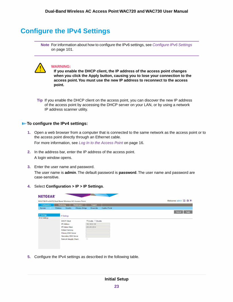
To configure the IPv4 settings:
1. Open a web browser from a computer that is connected to the same network as the access point or tothe access point directly through an Ethernet cable.
For more information, see Log In to the Access Point on page 16.
2. In the address bar, enter the IP address of the access point.
A login window opens.
3. Enter the user name and password.
The user name is admin. The default password is password. The user name and password arecase-sensitive.
4. Select Configuration > IP > IP Settings.
5. Configure the IPv4 settings as described in the following table.
Initial Setup
23
Dual-Band Wireless AC Access Point WAC720 and WAC730 User Manual
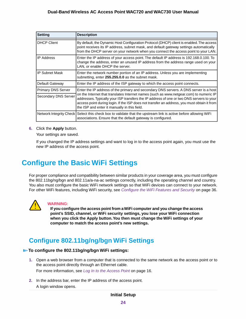
DescriptionSetting
By default, the Dynamic Host Configuration Protocol (DHCP) client is enabled.The accesspoint receives its IP address, subnet mask, and default gateway settings automaticallyfrom the DHCP server on your network when you connect the access point to your LAN.
DHCP Client
Enter the IP address of your access point. The default IP address is 192.168.0.100. Tochange the address, enter an unused IP address from the address range used on yourLAN, or enable DHCP the server.
IP Address
Enter the network number portion of an IP address. Unless you are implementingsubnetting, enter 255.255.0.0 as the subnet mask.
IP Subnet Mask
Enter the IP address of the ISP gateway to which the access point connects.Default Gateway
Enter the IP address of the primary and secondary DNS servers. A DNS server is a hoston the Internet that translates Internet names (such as www.netgear.com) to numeric IPaddresses.Typically your ISP transfers the IP address of one or two DNS servers to youraccess point during login. If the ISP does not transfer an address, you must obtain it fromthe ISP and enter it manually in this field.
Primary DNS Server
Secondary DNS Server
Select this check box to validate that the upstream link is active before allowing WiFiassociations. Ensure that the default gateway is configured.
Network Integrity Check
6. Click the Apply button.
Your settings are saved.
If you changed the IP address settings and want to log in to the access point again, you must use thenew IP address of the access point.
Configure the Basic WiFi Settings
For proper compliance and compatibility between similar products in your coverage area, you must configurethe 802.11bg/ng/bgn and 802.11a/a-na-ac settings correctly, including the operating channel and country.You also must configure the basic WiFi network settings so that WiFi devices can connect to your network.For other WiFi features, including WiFi security, see Configure the WiFi Features and Security on page 36.
WARNING:If you configure the access point from a WiFi computer and you change the accesspoint’s SSID, channel, or WiFi security settings, you lose your WiFi connectionwhen you click the Apply button.You then must change the WiFi settings of yourcomputer to match the access point’s new settings.
Configure 802.11bg/ng/bgn WiFi SettingsTo configure the 802.11bg/ng/bgn WiFi settings:
1. Open a web browser from a computer that is connected to the same network as the access point or tothe access point directly through an Ethernet cable.
For more information, see Log In to the Access Point on page 16.
2. In the address bar, enter the IP address of the access point.
A login window opens.
Initial Setup
24
Dual-Band Wireless AC Access Point WAC720 and WAC730 User Manual
3. Enter the user name and password.
The user name is admin. The default password is password. The user name and password arecase-sensitive.
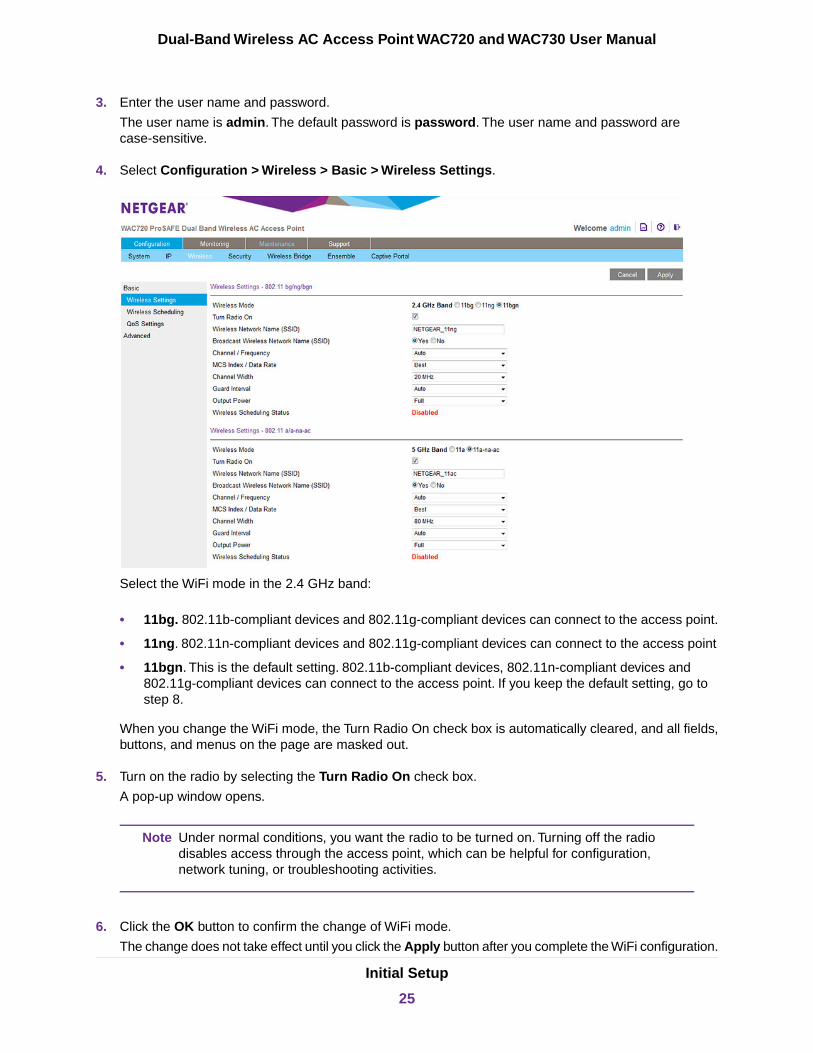
4. Select Configuration > Wireless > Basic > Wireless Settings.
Select the WiFi mode in the 2.4 GHz band:
• 11bg. 802.11b-compliant devices and 802.11g-compliant devices can connect to the access point.
• 11ng. 802.11n-compliant devices and 802.11g-compliant devices can connect to the access point
• 11bgn. This is the default setting. 802.11b-compliant devices, 802.11n-compliant devices and802.11g-compliant devices can connect to the access point. If you keep the default setting, go tostep 8.
When you change the WiFi mode, the Turn Radio On check box is automatically cleared, and all fields,buttons, and menus on the page are masked out.
5. Turn on the radio by selecting the Turn Radio On check box.
A pop-up window opens.
Under normal conditions, you want the radio to be turned on. Turning off the radiodisables access through the access point, which can be helpful for configuration,network tuning, or troubleshooting activities.
Note
6. Click the OK button to confirm the change of WiFi mode.
The change does not take effect until you click the Apply button after you complete the WiFi configuration.
Initial Setup
25
Dual-Band Wireless AC Access Point WAC720 and WAC730 User Manual

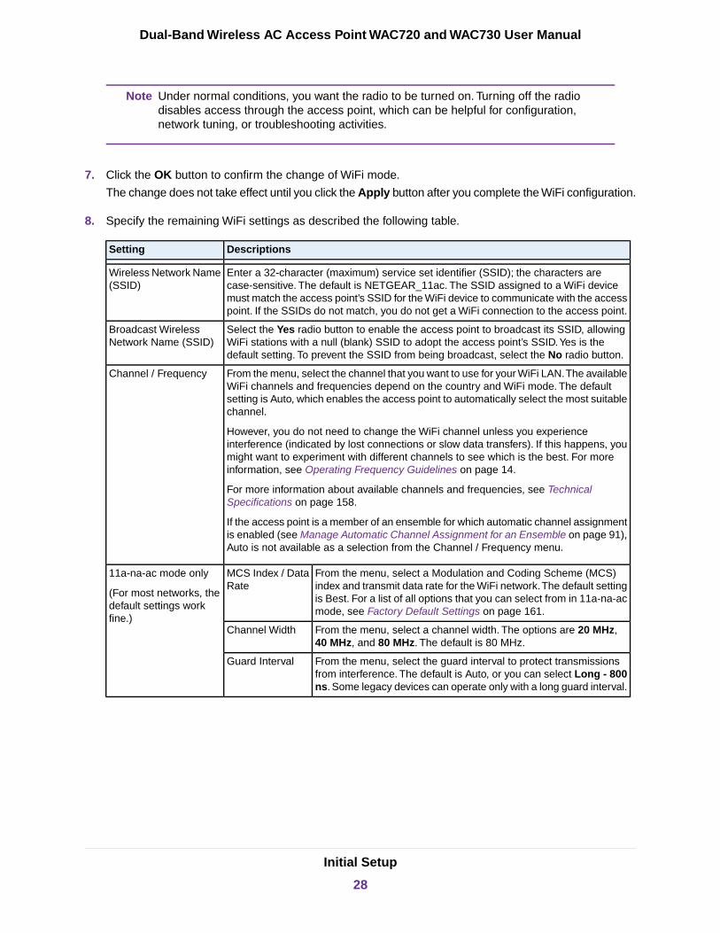
7. Specify the remaining WiFi settings as described the following table.
DescriptionsSetting
Enter a 32-character (maximum) service set identifier (SSID); the characters arecase-sensitive. The default is NETGEAR_11ng. The SSID assigned to a WiFi devicemust match the access point’s SSID for the WiFi device to communicate with the accesspoint. If the SSIDs do not match, you do not get a WiFi connection to the access point.
Wireless Network Name(SSID)
Select the Yes radio button to enable the access point to broadcast its SSID, allowingWiFi stations with a null (blank) SSID to adopt the access point’s SSID.Yes is thedefault setting. To prevent the SSID from being broadcast, select the No radio button.
Broadcast WirelessNetwork Name (SSID)
From the menu, select the channel that you want to use for your WiFi LAN.The availableWiFi channels and frequencies depend on the country and WiFi mode. The defaultsetting is Auto, which enables the access point to automatically select the most suitablechannel.
However, you do not need to change the WiFi channel unless you experienceinterference (indicated by lost connections or slow data transfers). If this happens, youmight want to experiment with different channels to see which is the best. For moreinformation, see Operating Frequency Guidelines on page 14.
For more information about available channels and frequencies, see TechnicalSpecifications on page 158.
If the access point is a member of an ensemble for which automatic channel assignmentis enabled (see Manage Automatic Channel Assignment for an Ensemble on page 91),Auto is not available as a selection from the Channel / Frequency menu.
Channel / Frequency
From the menu, select a Modulation and Coding Scheme (MCS)index and transmit data rate for the WiFi network.The default settingis Best. For a list of all options that you can select from in 11ng and11bgn modes, see Factory Default Settings on page 161.
MCS Index / DataRate
11ng and 11bgn modesonly
(For most networks, thedefault settings workfine.) From the menu, select a channel width. The options are 20 MHz
and 40 MHz. The default is 40 MHz.Channel Width
From the menu, select the guard interval to protect transmissionsfrom interference. The default is Auto, or you can select Long - 800ns. Some legacy devices can operate only with a long guard interval.
Guard Interval
From the menu, select the transmit data rate of the WiFi network.The default setting is Best. For a list of all options that you can selectfrom in 11bg mode, see Factory Default Settings on page 161.
Data Rate11bg modes only
From the menu, select the transmission power of the access point: Full, Half, Quarter,Eighth, Minimum. The default is Full.
Increasing the power improves performance, but if two or more access points areoperating in the same area and on the same channel, interference can occur.
Make sure that you comply with the regulatory requirements for total radio frequency(RF) output power in your country.
Output Power
8. Click the Apply button.
Your settings are saved.
For information about how to configure advanced WiFi settings, see ConfigureAdvanced WiFi Settings on page 106.
Note
Initial Setup
26
Dual-Band Wireless AC Access Point WAC720 and WAC730 User Manual

Configure 802.11a/a-na-ac WiFi SettingsTo configure the 802.11a/a-na-ac WiFi settings:
1. Open a web browser from a computer that is connected to the same network as the access point or tothe access point directly through an Ethernet cable.
For more information, see Log In to the Access Point on page 16.
2. In the address bar, enter the IP address of the access point.
A login window opens.
3. Enter the user name and password.
The user name is admin. The default password is password. The user name and password arecase-sensitive.
4. Select Configuration > Wireless > Basic > Wireless Settings.
5. Select the WiFi mode in the 5 GHz band:
• 11a. 802.11n-compliant devices can connect to the access point because they are backwardcompatible.
• 11a-na-ac. This is the default setting. If you keep the default setting, go to step 8.
When you change the WiFi mode, the Turn Radio On check box is automatically cleared, and all fields,buttons, and menus on the page are masked out.
6. Turn on the radio by selecting the Turn Radio On check box.
A pop-up window opens.
Initial Setup
27
Dual-Band Wireless AC Access Point WAC720 and WAC730 User Manual
Under normal conditions, you want the radio to be turned on. Turning off the radiodisables access through the access point, which can be helpful for configuration,network tuning, or troubleshooting activities.
Note
7. Click the OK button to confirm the change of WiFi mode.
The change does not take effect until you click the Apply button after you complete the WiFi configuration.
8. Specify the remaining WiFi settings as described the following table.
DescriptionsSetting
Enter a 32-character (maximum) service set identifier (SSID); the characters arecase-sensitive. The default is NETGEAR_11ac. The SSID assigned to a WiFi devicemust match the access point’s SSID for the WiFi device to communicate with the accesspoint. If the SSIDs do not match, you do not get a WiFi connection to the access point.
Wireless Network Name(SSID)
Select the Yes radio button to enable the access point to broadcast its SSID, allowingWiFi stations with a null (blank) SSID to adopt the access point’s SSID.Yes is thedefault setting. To prevent the SSID from being broadcast, select the No radio button.
Broadcast WirelessNetwork Name (SSID)
From the menu, select the channel that you want to use for your WiFi LAN.The availableWiFi channels and frequencies depend on the country and WiFi mode. The defaultsetting is Auto, which enables the access point to automatically select the most suitablechannel.
However, you do not need to change the WiFi channel unless you experienceinterference (indicated by lost connections or slow data transfers). If this happens, youmight want to experiment with different channels to see which is the best. For moreinformation, see Operating Frequency Guidelines on page 14.
For more information about available channels and frequencies, see TechnicalSpecifications on page 158.
If the access point is a member of an ensemble for which automatic channel assignmentis enabled (see Manage Automatic Channel Assignment for an Ensemble on page 91),Auto is not available as a selection from the Channel / Frequency menu.
Channel / Frequency
From the menu, select a Modulation and Coding Scheme (MCS)index and transmit data rate for the WiFi network.The default settingis Best. For a list of all options that you can select from in 11a-na-acmode, see Factory Default Settings on page 161.
MCS Index / DataRate
11a-na-ac mode only
(For most networks, thedefault settings workfine.)
From the menu, select a channel width. The options are 20 MHz,40 MHz, and 80 MHz. The default is 80 MHz.
Channel Width
From the menu, select the guard interval to protect transmissionsfrom interference. The default is Auto, or you can select Long - 800ns. Some legacy devices can operate only with a long guard interval.
Guard Interval
Initial Setup
28
Dual-Band Wireless AC Access Point WAC720 and WAC730 User Manual
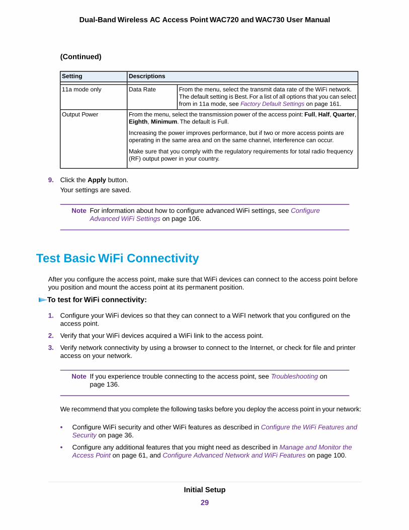
(Continued)
DescriptionsSetting
From the menu, select the transmit data rate of the WiFi network.The default setting is Best. For a list of all options that you can selectfrom in 11a mode, see Factory Default Settings on page 161.
Data Rate11a mode only
From the menu, select the transmission power of the access point: Full, Half, Quarter,Eighth, Minimum. The default is Full.
Increasing the power improves performance, but if two or more access points areoperating in the same area and on the same channel, interference can occur.
Make sure that you comply with the regulatory requirements for total radio frequency(RF) output power in your country.
Output Power
9. Click the Apply button.
Your settings are saved.
For information about how to configure advanced WiFi settings, see ConfigureAdvanced WiFi Settings on page 106.
Note
Test Basic WiFi Connectivity
After you configure the access point, make sure that WiFi devices can connect to the access point beforeyou position and mount the access point at its permanent position.
To test for WiFi connectivity:
1. Configure your WiFi devices so that they can connect to a WiFI network that you configured on theaccess point.
2. Verify that your WiFi devices acquired a WiFi link to the access point.
3. Verify network connectivity by using a browser to connect to the Internet, or check for file and printeraccess on your network.
If you experience trouble connecting to the access point, see Troubleshooting onpage 136.
Note
We recommend that you complete the following tasks before you deploy the access point in your network:
• Configure WiFi security and other WiFi features as described in Configure the WiFi Features andSecurity on page 36.
• Configure any additional features that you might need as described in Manage and Monitor theAccess Point on page 61, and Configure Advanced Network and WiFi Features on page 100.
Initial Setup
29
Dual-Band Wireless AC Access Point WAC720 and WAC730 User Manual

After you complete the configuration of the access point, you can reconfigure the computer that youused for this process back to its original TCP/IP settings.
Mount the Access Point
The following sections explain how to mount your access point.We recommend that you review the informationin WiFi Equipment Placement and Range Guidelines on page 13 before you mount the access point at itspermanent position.
• Package Content of the Ceiling and Wall Installation Kit on page 30
• Mount the Access Point to a Drop Ceiling on page 30
• Mount the Access Point to a Wall on page 33
Package Content of the Ceiling and Wall Installation Kit
Figure 5. Ceiling and wall installation kit
The ceiling and wall installation kit contains the following components:
1. One access point mounting bracket
2. One wall mounting bracket
3. Four mounting screws with integrated washers for the access point mounting bracket
4. One T-bar screw for the access point mounting bracket
5. Four wall screws for the wall mounting bracket
6. Four wall anchors for the wall mounting bracket
Mount the Access Point to a Drop CeilingThe best location for ceiling installation is at the center of your WiFi coverage area, and within line of sightof all mobile devices. Make sure that the top (the dome side) of the access point is directed toward the usersand not the ceiling. Do not place the access point in a false ceiling space facing up.
Initial Setup
30
Dual-Band Wireless AC Access Point WAC720 and WAC730 User Manual

Before mounting the access point in a high location, first set up and test the access point to verify WiFinetwork connectivity.
If you are mounting the access point on a hard ceiling, use the wall installation instructions.
To mount the access point to a drop ceiling:
1. Locate the access point mounting bracket, four mounting screws, and T-bar screw in the product package.
2. Attach the access point mounting bracket to the access point using the four mounting screws.
3. Place the access point so that the ceiling rail is between the two tabs on the access point mountingbracket.
Initial Setup
31
Dual-Band Wireless AC Access Point WAC720 and WAC730 User Manual
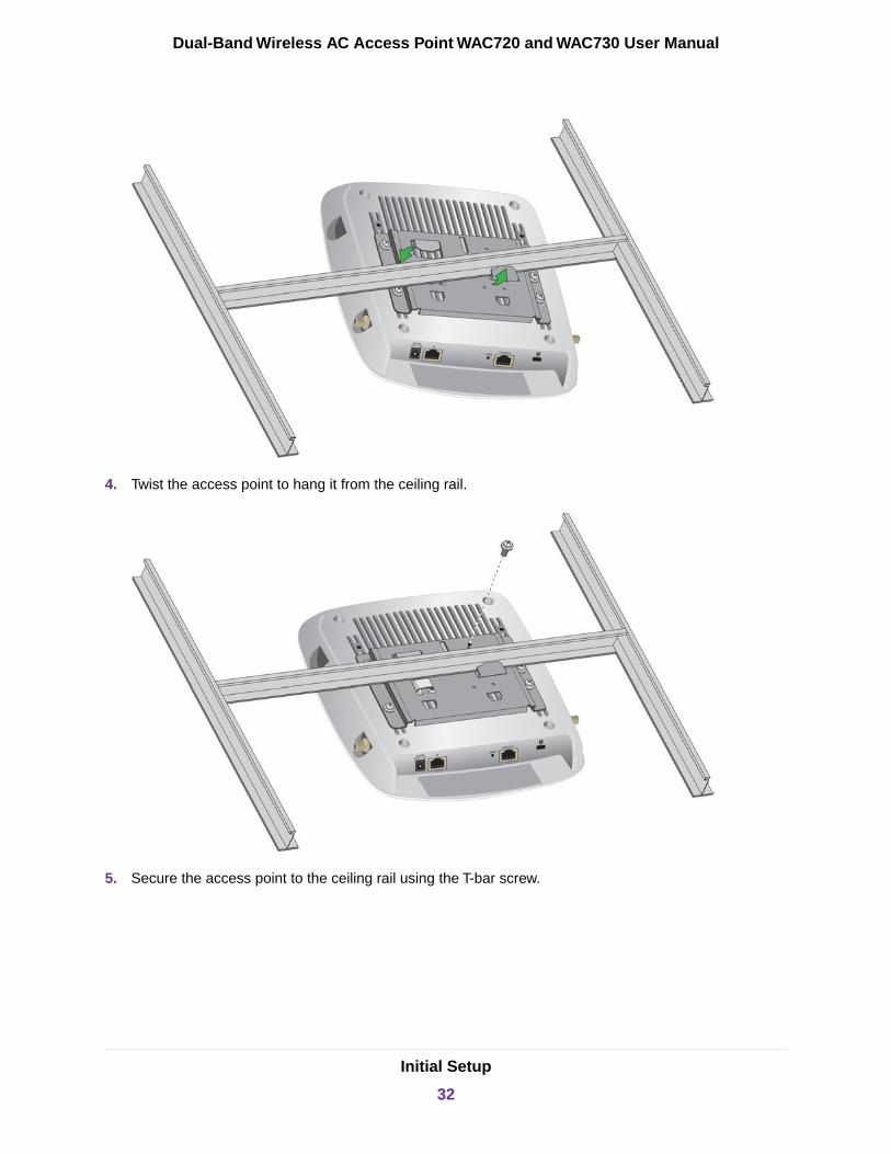
4. Twist the access point to hang it from the ceiling rail.
5. Secure the access point to the ceiling rail using the T-bar screw.
Initial Setup
32
Dual-Band Wireless AC Access Point WAC720 and WAC730 User Manual

Mount the Access Point to a WallThe best location for wall installation is at the center of your WiFi coverage area, and within line of sight ofall mobile devices. Make sure that the top (the dome side) of the access point is directed toward the usersand not the wall.
To mount the access point to a wall:
1. Locate the wall mounting bracket, access point bracket, four mounting screws, and wall anchors andscrews in the product package.
2. Place the wall mounting bracket on the wall where you want to mount the access point.
3. Mark the wall where the two mounting holes are (see the figure in step 6).
4. Attach the access point mounting bracket to the access point using the four mounting screws as shown.
5. So you can see how the brackets fit together, attach the wall mounting bracket to the access pointmounting bracket as shown in the following figure. The three hooks on the wall mounting bracket fit intothe three holes on the access point mounting bracket. The handle on the wall mounting bracket alsofits into a hole on the access point bracket. Release the wall mounting bracket by moving the handle.
Initial Setup
33
Dual-Band Wireless AC Access Point WAC720 and WAC730 User Manual
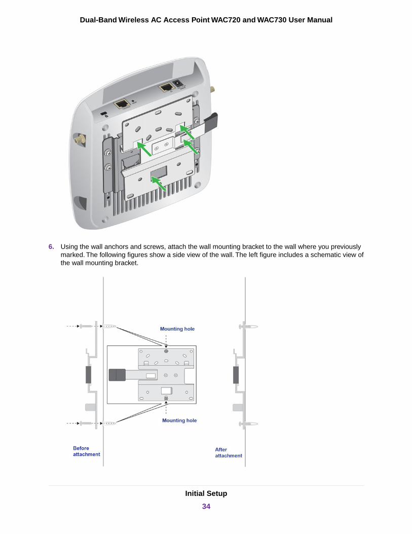
6. Using the wall anchors and screws, attach the wall mounting bracket to the wall where you previouslymarked. The following figures show a side view of the wall. The left figure includes a schematic view ofthe wall mounting bracket.
Initial Setup
34
Dual-Band Wireless AC Access Point WAC720 and WAC730 User Manual

Although the product package includes four wall anchors and screws, two screws aresufficient to attach the wall mounting bracket as shown in the previous figure. However,if you prefer, you can use four screws and insert them through the mounting holes inthe corners of the wall mounting bracket.
Note
7. Align the three holes on the access point bracket with the three hooks on the wall mounting bracket andslide the access point down until it click-attaches to the wall mounting bracket and is secured. Thefollowing figures show a side view of the wall.
Initial Setup
35
Dual-Band Wireless AC Access Point WAC720 and WAC730 User Manual

3Configure the WiFi Features and Security
This chapter describes how to configure the WiFi features of the access point.
The chapter includes the following sections:
• WiFi Data Security Options• WiFi Security Profiles• Configure RADIUS Server Settings• Manage MAC Address Filter Profiles in the Local MAC Address Database• Enable Rogue AP Detection and Monitor Rogue APs• Schedule the WiFi Radios to Be Turned Off• Configure Basic WiFi Quality of Service
Before you set up WiFi security and additional WiFi features that are described in this chapter, connect theaccess point, get the Internet connection working, and configure the 802.11bg/ng/bgn and 802.11a/a-na-ac WiFisettings as described in Initial Setup on page 12. The access point functions with an Ethernet LAN connection.Make sure that you verify WiFi connectivity before you set up WiFi security and additional WiFi features.
If you are configuring the access point from a WiFi computer and you change the accesspoint’s SSID, channel, or WiFi security settings, you lose your WiFi connection when yousave the settings.You must then change the WiFi settings of your computer to match theaccess point’s new settings.
Note
36
WiFi Data Security Options
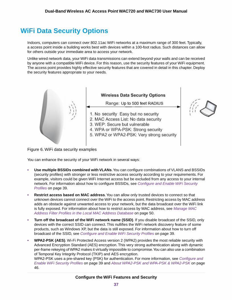
Indoors, computers can connect over 802.11ac WiFi networks at a maximum range of 300 feet. Typically,a access point inside a building works best with devices within a 100-foot radius. Such distances can allowfor others outside your immediate area to access your network.
Unlike wired network data, your WiFi data transmissions can extend beyond your walls and can be receivedby anyone with a compatible WiFi device. For this reason, use the security features of your WiFi equipment.The access point provides highly effective security features that are covered in detail in this chapter. Deploythe security features appropriate to your needs.
Figure 6. WiFi data security examples
You can enhance the security of your WiFi network in several ways:
• Use multiple BSSIDs combined with VLANs.You can configure combinations of VLANS and BSSIDs(security profiles) with stronger or less restrictive access security according to your requirements. Forexample, visitors could be given WiFi Internet access but be excluded from any access to your internalnetwork. For information about how to configure BSSIDs, see Configure and Enable WiFi SecurityProfiles on page 39.
• Restrict access based on MAC address.You can allow only trusted devices to connect so thatunknown devices cannot connect over the WiFi to the access point. Restricting access by MAC addressadds an obstacle against unwanted access to your network, but the data broadcast over the WiFi linkis fully exposed. For information about how to restrict access by MAC address, see Manage MACAddress Filter Profiles in the Local MAC Address Database on page 50.
• Turn off the broadcast of the WiFi network name (SSID). If you disable broadcast of the SSID, onlydevices with the correct SSID can connect. This nullifies the WiFi network discovery feature of someproducts, such as Windows XP, but the data is still exposed. For information about how to turn offbroadcast of the SSID, see Configure and Enable WiFi Security Profiles on page 39.
• WPA2-PSK (AES). Wi-Fi Protected Access version 2 (WPA2) provides the most reliable security withAdvanced Encryption Standard (AES) encryption. This very strong authentication along with dynamicper-frame rekeying of WPA2 makes it virtually impossible to compromise.You can also use a combinationof Temporal Key Integrity Protocol (TKIP) and AES encryption.WPA2-PSK uses a pre-shared key (PSK) for authentication. For more information, see Configure andEnable WiFi Security Profiles on page 39 and About WPA2-PSK and WPA-PSK & WPA2-PSK on page46.
Configure the WiFi Features and Security
37
Dual-Band Wireless AC Access Point WAC720 and WAC730 User Manual
• WPA2 with RADIUS. Wi-Fi Protected Access version 2 (WPA2) with a RADIUS server provides themost reliable security with Advanced Encryption Standard (AES) encryption. This very strongauthentication along with dynamic per-frame rekeying of WPA2 makes it virtually impossible tocompromise.WPA2 uses RADIUS-based 802.1x authentication. For more information, see Configure and EnableWiFi Security Profiles on page 39. and About WPA2 With RADIUS and WPA & WPA2 With RADIUSon page 47
• WPA-PSK & WPA2-PSK mixed mode. This mode provides reliable security for both WPA-PSK andWPA2-PSK clients. Encryption is supported with the TKIP + AES mode.WPA-PSK & WPA2-PSK uses a pre-shared key (PSK) for authentication; for more information, seeConfigure and Enable WiFi Security Profiles on page 39 and About WPA2-PSK and WPA-PSK &WPA2-PSK on page 46.
• WPA & WPA2 mixed mode with RADIUS. This mode provides reliable security for both WPA andWPA2 clients and a RADIUS server. Encryption is supported with the TKIP + AES mode.WPA & WPA2 uses RADIUS-based 802.1x authentication. For more information, see Configure andEnable WiFi Security Profiles on page 39 and About WPA2 With RADIUS and WPA & WPA2 WithRADIUS on page 47.
WiFi Security Profiles
WiFi security profiles, simply referred to as security profiles, let you configure unique security settings foreach SSID on each radio of the access point. For each radio, the access point supports up to 8 WiFi securityprofiles (BSSIDs).That means that you can configure 16 security profiles with custom settings (see Configureand Enable WiFi Security Profiles on page 39).
To set up a security profile, select its network authentication type, data encryption, WiFi client securityseparation, and VLAN ID:
• Network authentication. The access point is set by default as an open system with no authentication.When you configure network authentication, bear in mind that some legacy WiFi devices do not supportWPA2. If your network includes computers with legacy WiFi devices, configure WPA & WPA2 mixedmode.For information about the types of network authentication that the access point supports, see Configureand Enable WiFi Security Profiles on page 39.
• Data encryption. Select the data encryption that you want to use. The available options depend on thenetwork authentication setting (otherwise, data encryption is disabled by default). The data encryptionsettings are explained in Configure and Enable WiFi Security Profiles on page 39.
• WiFi client security separation. If this feature is enabled, the associated WiFi clients (using the sameSSID) are not able to communicate with 1each other.This feature is useful for hotspots and other publicaccess situations. By default, WiFi client separation is disabled. For more information, see Configureand Enable WiFi Security Profiles on page 39.
• VLAN ID. If this feature is enabled and if the network devices (hubs and switches) on your LAN supportthe VLAN (802.1Q) standard, the default VLAN ID for the access point is associated with each profile.The default VLAN ID must match the IDs that are used by the other network devices. For moreinformation, see Configure and Enable WiFi Security Profiles on page 39.
Configure the WiFi Features and Security
38
Dual-Band Wireless AC Access Point WAC720 and WAC730 User Manual

Some concepts and guidelines regarding the SSID are explained in the following list:
• A basic service set (BSS) is a group of WiFi stations and a single access point, all using the samesecurity profile or service set identifier (BSSID). The actual identifier in the BSSID is the MAC addressof the WiFi radio. (A WiFi radio can be assigned multiple MAC addresses, one for each security profile.)
• An extended service set (ESS) is a group of WiFi stations and multiple access points, all using the sameidentifier (ESSID).
• Different access points within an ESS can use different channels. To reduce interference, specify thatadjacent access points use different channels.
• Roaming is the ability of WiFi stations to connect over WiFi when they physically move from one BSSto another one within the same ESS. The WiFi station automatically changes to the access point withthe least interference or best performance.
Configure and Enable WiFi Security ProfilesThe access point support 16 WiFi security profiles, 8 on each radio.
A WiFi security profile defines the following characteristics for an individual WiFi network:
• Profile Definition. Lets you specify the profile name, WiFi network name (SSID), whether the SSID isbroadcast, band steering, RSSI threshold, MAC authentication, 802.11K radio resource management(RRM), and WiFi client separation of the WiFi network.
• Wireless Scheduling. Lets you specify an on and off schedule for broadcast of the WiFi network. (Forinformation about on and off scheduling of a radio, which affects all WiFi networks on the radio, seeSchedule the WiFi Radios to Be Turned Off on page 57.)
• Authentication Settings. Lets you specify the network authentication, data encryption, and VLAN IDof the WiFi network.
• QoS Policies. Lets you specify the QoS policy and bandwidth limit of the WiFi network.
• Captive Portal. Lets you assign a captive portal profile to the WiFi network.
To configure and enable a WiFi security profile, you must enable the associated radio:
• For 802.11bg/ng/bgn modes, the 2.4 GHz radio must be enabled (see Configure 802.11bg/ng/bgn WiFiSettings on page 24).
• For 802.11a/a-na-ac modes, the 5 GHz radio must be enabled. (see Configure 802.11a/a-na-ac WiFiSettings on page 27).
Both radios can function concurrently and both radios are enabled by default.
To configure and enable a WiFi security profile:
1. Open a web browser from a computer that is connected to the same network as the access point or tothe access point directly through an Ethernet cable.
For more information, see Log In to the Access Point on page 16.
2. In the address bar, enter the IP address of the access point.
A login window opens.
3. Enter the user name and password.
Configure the WiFi Features and Security
39
Dual-Band Wireless AC Access Point WAC720 and WAC730 User Manual

The user name is admin. The default password is password. The user name and password arecase-sensitive.
4. Select Configuration > Security > Profile Settings.
The Profile Settings page for the 802.11bg/ng/bgn and 802.11a/a-na-ac modes shows eight WiFi securityprofiles for each mode. (If the 2.4 GHz radio is disabled, the Enable column is masked out.)
The following table explains the fields of the Profile Settings page.
DescriptionSetting
The unique name of the security profile that makes it easy to recognize the profile.Profile Name
The WiFi network name (SSID) for the security profile.SSID
The configured WiFi authentication method for the security profile.Security
The default VLAN ID that is associated with the security profile.VLAN
The check box that specifies whether the security profile is enabled. If you select the check boxand click the Apply button, the security profile is enabled.
You cannot disable security profile #0 (NETGEAR) for either radio band. To disable this securityprofile, turn off the radio for the radio band (see Configure 802.11bg/ng/bgn WiFi Settings on page24 and Configure 802.11a/a-na-ac WiFi Settings on page 27).
Enable
The check box that specifies whether Wireless Multicast Forwarding (WMF) is enabled. If you selectthe check box and click the Apply button, WMF is enabled.
WMF is required for applications that use multicasting, such as VLC streaming applications. WhenWMF is enabled, the access point converts multicast traffic to unicast traffic. WMF improves theoverall performance because the access points transmits data according to the capability of eachWiFi client.
WMF-Enable
5. To configure a WiFi security profile, select the corresponding radio button to the left of the WiFi securityprofile.
Configure the WiFi Features and Security
40
Dual-Band Wireless AC Access Point WAC720 and WAC730 User Manual
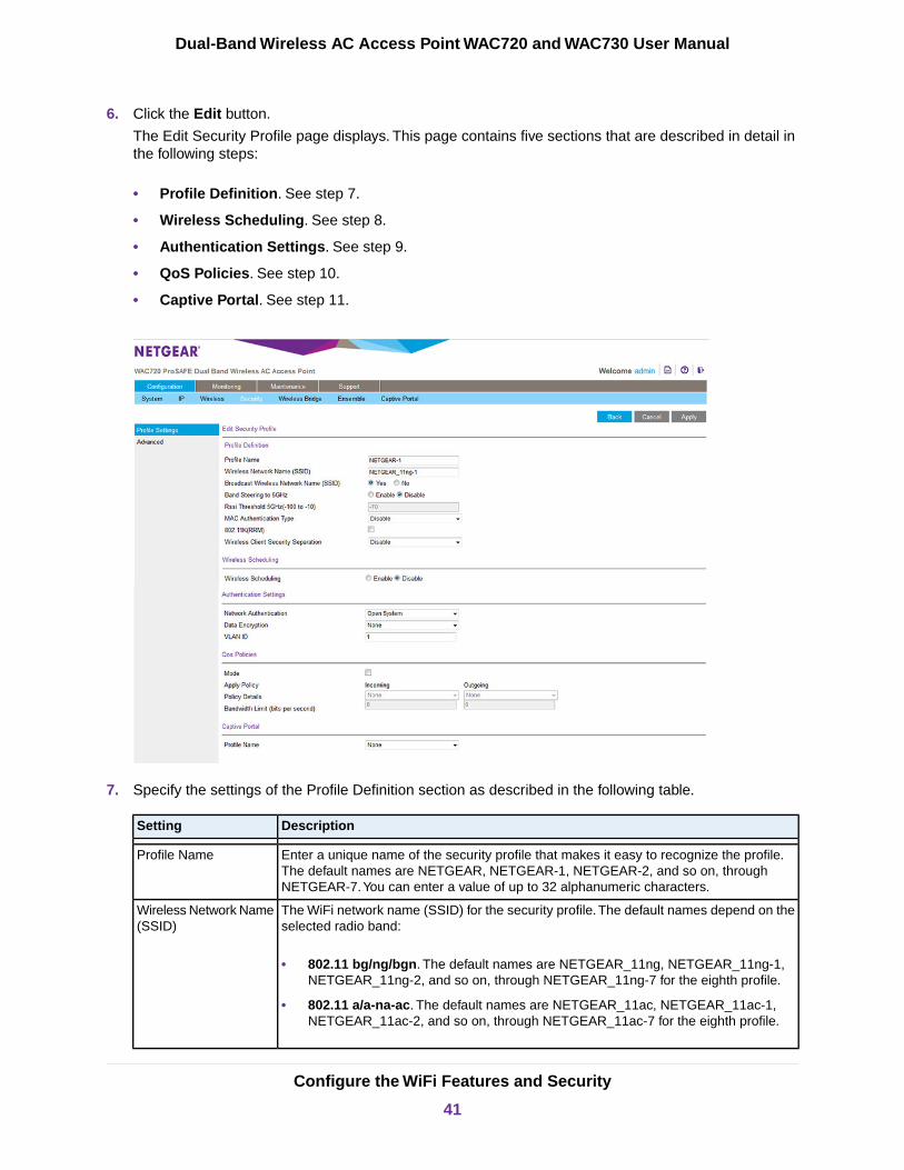
6. Click the Edit button.
The Edit Security Profile page displays. This page contains five sections that are described in detail inthe following steps:
• Profile Definition. See step 7.
• Wireless Scheduling. See step 8.
• Authentication Settings. See step 9.
• QoS Policies. See step 10.
• Captive Portal. See step 11.
7. Specify the settings of the Profile Definition section as described in the following table.
DescriptionSetting
Enter a unique name of the security profile that makes it easy to recognize the profile.The default names are NETGEAR, NETGEAR-1, NETGEAR-2, and so on, throughNETGEAR-7.You can enter a value of up to 32 alphanumeric characters.
Profile Name
The WiFi network name (SSID) for the security profile. The default names depend on theselected radio band:
• 802.11 bg/ng/bgn. The default names are NETGEAR_11ng, NETGEAR_11ng-1,NETGEAR_11ng-2, and so on, through NETGEAR_11ng-7 for the eighth profile.
• 802.11 a/a-na-ac. The default names are NETGEAR_11ac, NETGEAR_11ac-1,NETGEAR_11ac-2, and so on, through NETGEAR_11ac-7 for the eighth profile.
Wireless Network Name(SSID)
Configure the WiFi Features and Security
41
Dual-Band Wireless AC Access Point WAC720 and WAC730 User Manual
(Continued)
DescriptionSetting
Select the Yes radio button to enable the access point to broadcast its SSID, allowingWiFi stations with a null (blank) SSID to adopt the access point’s SSID.Yes is the defaultsetting. To prevent the SSID from being broadcast, select the No radio button.
Broadcast WirelessNetwork Name (SSID)
Select the Enable radio button to enable band steering from the 2.4 GHz band to the 5GHz band. Band steering can reduce the client density in the 2.4 GHz band by steeringdual-band-capable clients to the 5 GHz band, thereby increasing the WiFi network capacity.By default, the Disable button is selected and band steering is disabled.
If you enable band steering, you can set the RSSI threshold.
Band Steering to 5GHz
This setting does notapply to802.11a/a-na-acprofiles.
The received signal strength indicator (RSSI) threshold applies only if you enable bandsteering.
Enter the minimum RSSI value that a dual-band-capable client must be able to receivefrom a 5 GHz radio before the client is steered from a 2.4 GHz radio to the 5 GHz radio.
You can enter a value from –100 to –10. The default value is –70.
Rssi Threshold 5GHz(-100 to -10)
This setting does notapply to802.11a/a-na-acprofiles.
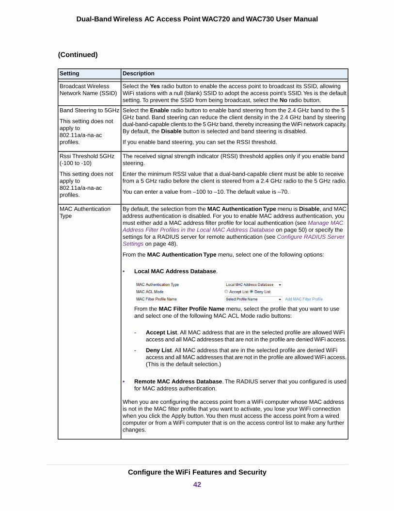
By default, the selection from the MAC Authentication Type menu is Disable, and MACaddress authentication is disabled. For you to enable MAC address authentication, youmust either add a MAC address filter profile for local authentication (see Manage MACAddress Filter Profiles in the Local MAC Address Database on page 50) or specify thesettings for a RADIUS server for remote authentication (see Configure RADIUS ServerSettings on page 48).
From the MAC Authentication Type menu, select one of the following options:
• Local MAC Address Database.
From the MAC Filter Profile Name menu, select the profile that you want to useand select one of the following MAC ACL Mode radio buttons:
- Accept List. All MAC address that are in the selected profile are allowed WiFiaccess and all MAC addresses that are not in the profile are denied WiFi access.
- Deny List. All MAC address that are in the selected profile are denied WiFiaccess and all MAC addresses that are not in the profile are allowed WiFi access.(This is the default selection.)
• Remote MAC Address Database. The RADIUS server that you configured is usedfor MAC address authentication.
When you are configuring the access point from a WiFi computer whose MAC addressis not in the MAC filter profile that you want to activate, you lose your WiFi connectionwhen you click the Apply button.You then must access the access point from a wiredcomputer or from a WiFi computer that is on the access control list to make any furtherchanges.
MAC AuthenticationType
Configure the WiFi Features and Security
42
Dual-Band Wireless AC Access Point WAC720 and WAC730 User Manual

(Continued)
DescriptionSetting
Select the 802.11K(RRM) check box to allow the access point to support 802.11K radioresource management (RRM). 802.11K RRM allows for a better utilization of accesspoints in a network. If some access points are underutilized because their signal is notas strong as that of other access points in the network and those other access points areused to their maximum capacity, 802.11K RRM can steer clients to the underutilizedaccess points. By default, the 802.11K(RRM) check box is cleared and 802.11K RRM isdisabled.
802.11K (RRM)
WiFi client separation is intended for hotspots and other public access situations. Makeone of the following selections from the menu:
• Select the Enable radio button to enable WiFi client security separation. Clients thatare connected to the WiFi network are prevented from communicating with eachother.
• By default, the Disable button is selected and WiFi client security separation isdisabled. Clients that are connected to the WiFi network are allowed to communicatewith each other. This is the default selection.
Wireless Client SecuritySeparation
8. To specify a schedule that allows the access point to turn broadcast of the WiFi network on and off, dothe following:
a. Select the Wireless Scheduling Enable radio button.
The page expands to display scheduling options. By default, the Disable radio button is selectedand the scheduling options do not display.
The Wireless Scheduling radio buttons are not shown for the NETGEAR_11ngand NETGEAR_11ac SSIDs because you cannot specify a WiFi schedule forthese default WiFi networks. However, you can specify a WiFi schedule for a radio(see Schedule the WiFi Radios to Be Turned Off on page 57), which affects allWiFi networks on the radio, including the default WiFi network.
Note
b. From the Wireless Scheduling Type menu, select one of the following options:
• Everyday.The schedule applies every day of the week (Monday through Sunday). Set the startand end time for the schedule by moving the circles on the Security Profile On & Off Timebar. By default, this schedule enables the radio to be active from 7:00 a.m. to 6:30 p.m. (18:30).
• Weekdays. The schedule applies every weekday of the week (that is, Monday through Friday).Set the start and end time for the schedule by moving the circles on the Security Profile On
Configure the WiFi Features and Security
43
Dual-Band Wireless AC Access Point WAC720 and WAC730 User Manual
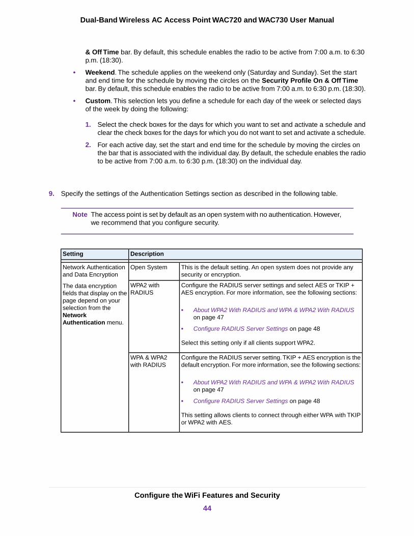
& Off Time bar. By default, this schedule enables the radio to be active from 7:00 a.m. to 6:30p.m. (18:30).
• Weekend. The schedule applies on the weekend only (Saturday and Sunday). Set the startand end time for the schedule by moving the circles on the Security Profile On & Off Timebar. By default, this schedule enables the radio to be active from 7:00 a.m. to 6:30 p.m. (18:30).
• Custom. This selection lets you define a schedule for each day of the week or selected daysof the week by doing the following:
1. Select the check boxes for the days for which you want to set and activate a schedule andclear the check boxes for the days for which you do not want to set and activate a schedule.
2. For each active day, set the start and end time for the schedule by moving the circles onthe bar that is associated with the individual day. By default, the schedule enables the radioto be active from 7:00 a.m. to 6:30 p.m. (18:30) on the individual day.
9. Specify the settings of the Authentication Settings section as described in the following table.
The access point is set by default as an open system with no authentication. However,we recommend that you configure security.
Note
DescriptionSetting
This is the default setting. An open system does not provide anysecurity or encryption.
Open SystemNetwork Authenticationand Data Encryption
The data encryptionfields that display on thepage depend on yourselection from theNetworkAuthentication menu.
Configure the RADIUS server settings and select AES or TKIP +AES encryption. For more information, see the following sections:
• About WPA2 With RADIUS and WPA & WPA2 With RADIUSon page 47
• Configure RADIUS Server Settings on page 48
Select this setting only if all clients support WPA2.
WPA2 withRADIUS
Configure the RADIUS server setting.TKIP + AES encryption is thedefault encryption. For more information, see the following sections:
• About WPA2 With RADIUS and WPA & WPA2 With RADIUSon page 47
• Configure RADIUS Server Settings on page 48
This setting allows clients to connect through either WPA with TKIPor WPA2 with AES.
WPA & WPA2with RADIUS
Configure the WiFi Features and Security
44
Dual-Band Wireless AC Access Point WAC720 and WAC730 User Manual

(Continued)
DescriptionSetting
Enter a WPA passphrase and select AES or TKIP + AES encryption.For more information, see About WPA2-PSK and WPA-PSK &WPA2-PSK on page 46.
Select this setting only if all clients support WPA2.
WPA2-PSKNetwork Authenticationand Data Encryption(continued)
Enter a WPA passphrase. TKIP + AES encryption is the defaultencryption. For more information, see About WPA2-PSK andWPA-PSK & WPA2-PSK on page 46.
This setting allows clients to connect through either WPA with TKIPor WPA2 with AES.
WPA-PSK &WPA2-PSK
Enter the VLAN ID to be associated with this security profile. The range for the VLANID is 1–4094. The default VLAN ID is 1.
The VLAN ID must match the VLAN ID that is used by the other devices in your network.
VLAN ID
10. Specify the settings of the QoS Policy section as described in the following table.
To be able to select a QoS policy, you must first configure one or more policies (seeConfigure and Manage Quality of Service Policies on page 112).
Note
DescriptionSetting
Select the Mode check box to enable the selection of QoS policies and bandwidthlimits.
Mode
Select a QoS policy from the Incoming menu, Outgoing menu, or both menus.
Depending on your selection, the policy is applied to incoming packets, outgoingpackets, or both incoming and outgoing packets, and is displayed in the PolicyDetails fields.
Policy Details
As an option, specify the bandwidth limits in bits per second (bps) for incoming traffic,outgoing traffic, or both traffic streams. For example, to set a limit of 1 Mbps, enter1048576 (or round down to 1000000).
Bandwidth Limit (bits persecond)
11. To assign a captive portal profile to the WiFi security profile, select a captive portal instance from theProfile Name menu (NETGEAR or NETGEAR-1).
To be able to select a captive portal instance, you must configure and enable at leastone captive portal instance and globally enable captive portals (see Manage CaptivePortals on page 120).
Note
12. Click the Apply button.
Your settings are saved.
Configure the WiFi Features and Security
45
Dual-Band Wireless AC Access Point WAC720 and WAC730 User Manual
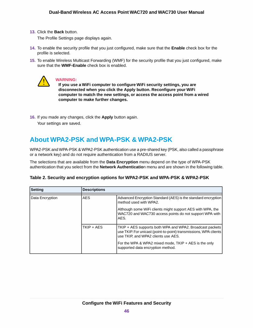
13. Click the Back button.
The Profile Settings page displays again.
14. To enable the security profile that you just configured, make sure that the Enable check box for theprofile is selected.
15. To enable Wireless Multicast Forwarding (WMF) for the security profile that you just configured, makesure that the WMF-Enable check box is enabled.
WARNING:If you use a WiFi computer to configure WiFi security settings, you aredisconnected when you click the Apply button. Reconfigure your WiFicomputer to match the new settings, or access the access point from a wiredcomputer to make further changes.
16. If you made any changes, click the Apply button again.
Your settings are saved.
About WPA2-PSK and WPA-PSK & WPA2-PSKWPA2-PSK and WPA-PSK & WPA2-PSK authentication use a pre-shared key (PSK, also called a passphraseor a network key) and do not require authentication from a RADIUS server.
The selections that are available from the Data Encryption menu depend on the type of WPA-PSKauthentication that you select from the Network Authentication menu and are shown in the following table.
Table 2. Security and encryption options for WPA2-PSK and WPA-PSK & WPA2-PSK
DescriptionsSetting
Advanced Encryption Standard (AES) is the standard encryptionmethod used with WPA2.
Although some WiFi clients might support AES with WPA, theWAC720 and WAC730 access points do not support WPA withAES.
AESData Encryption
TKIP + AES supports both WPA and WPA2. Broadcast packetsuse TKIP. For unicast (point-to-point) transmissions, WPA clientsuse TKIP, and WPA2 clients use AES.
For the WPA & WPA2 mixed mode, TKIP + AES is the onlysupported data encryption method.
TKIP + AES
Configure the WiFi Features and Security
46
Dual-Band Wireless AC Access Point WAC720 and WAC730 User Manual

Table 2. Security and encryption options for WPA2-PSK and WPA-PSK & WPA2-PSK(Continued)
DescriptionsSetting
Enter a passphrase. The passphrase length must be between 8 and 63 characters(inclusive). The default passphrase is sharedsecret.
You can display the actual passphrase by selecting the Show Passphrase in ClearText Yes radio button.
Passphrase
Select the Yes radio button to display the actual passphrase in the Passphrase field.The default setting is No.
Show Passphrase in ClearText
About WPA2 With RADIUS and WPA & WPA2 With RADIUSWPA2 and WPA & WPA2 security require RADIUS-based 802.1x authentication, so you also must defineRADIUS server settings. For information about RADIUS servers, see Configure RADIUS Server Settingson page 48.
The selections that are available from the Data Encryption menu depend on the type of WPA authenticationthat you select from the Network Authentication menu and are shown in the following table.
Table 3. Encryption options for WPA with RADIUS and WPA & WPA2 with RADIUS
DescriptionsSetting
Advanced Encryption Standard (AES) is the standard encryption method used with WPA2.
Although some WiFi clients might support AES with WPA, the WAC720 and WAC730 accesspoints do not support WPA with AES.
AES
The TKIP + AES encryption method is supported both for WPA and WPA2. Broadcast packetsuse TKIP. For unicast (point-to-point) transmissions, WPA clients use TKIP, and WPA2 clientsuse AES. For the WPA & WPA2 mixed mode, TKIP + AES is the only supported data encryptionmethod.
TKIP + AES
Change the QoS Policy for a WiFi Security ProfileTo change the QoS policy for a WiFi security profile:
1. Open a web browser from a computer that is connected to the same network as the access point or tothe access point directly through an Ethernet cable.
For more information, see Log In to the Access Point on page 16.
2. In the address bar, enter the IP address of the access point.
A login window opens.
3. Enter the user name and password.
The user name is admin. The default password is password. The user name and password arecase-sensitive.
4. Select Configuration > Security > Profile Settings.
Configure the WiFi Features and Security
47
Dual-Band Wireless AC Access Point WAC720 and WAC730 User Manual

The Profile Settings page displays.
5. Select the radio button the left of the security profile.
6. Click the Edit button.
The Edit Security Profile page displays.
7. From the menu from which you can select another QoS policy, select None.
8. Click the Apply button.
The old policy is removed from the security profile.
9. Select the new QoS policy from the same menu.
10. Click the Apply button.
Your settings are saved.
Configure RADIUS Server Settings
For authentication, accounting, or both authentication and accounting using RADIUS, you must configureprimary servers and optional secondary servers. These RADIUS server settings can apply to all devicesthat are connected to the access point.
You can configure both IPv4 and IPv6 servers. In the IPv4 RADIUS Server Settings section, enter IPv4addresses only. In the IPv6 RADIUS Server Settings section, enter IPv6 addresses only.
To configure the RADIUS server settings:
1. Open a web browser from a computer that is connected to the same network as the access point or tothe access point directly through an Ethernet cable.
For more information, see Log In to the Access Point on page 16.
2. In the address bar, enter the IP address of the access point.
A login window opens.
3. Enter the user name and password.
The user name is admin. The default password is password. The user name and password arecase-sensitive.
4. Select Configuration > Security > Advanced > RADIUS Server Settings.
Configure the WiFi Features and Security
48
Dual-Band Wireless AC Access Point WAC720 and WAC730 User Manual
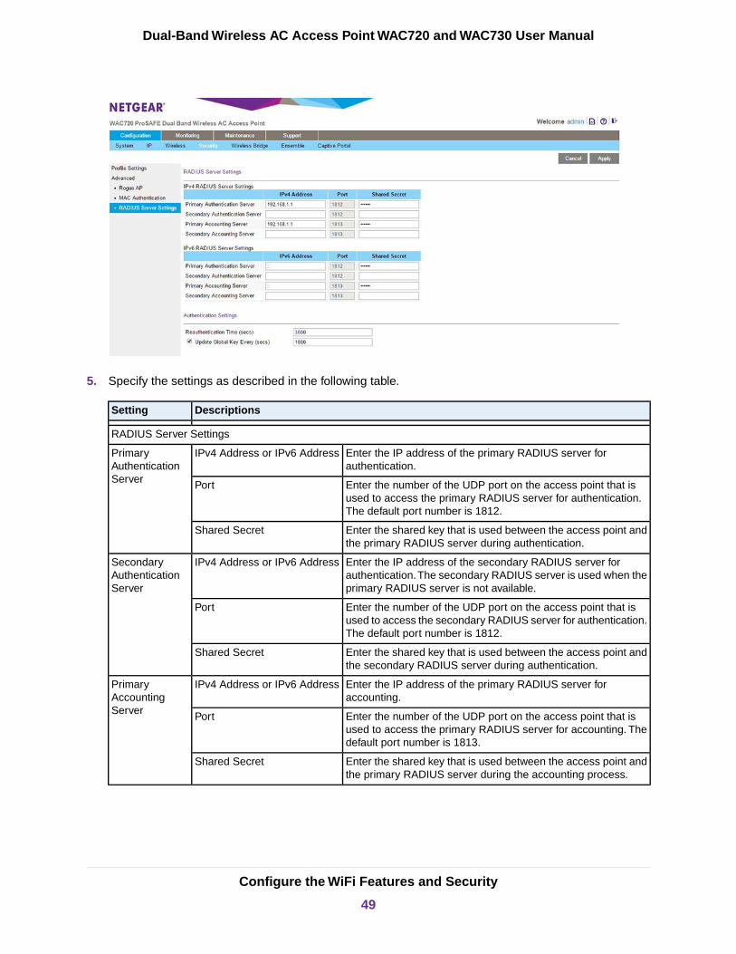
5. Specify the settings as described in the following table.
DescriptionsSetting
RADIUS Server Settings
Enter the IP address of the primary RADIUS server forauthentication.
IPv4 Address or IPv6 AddressPrimaryAuthenticationServer Enter the number of the UDP port on the access point that is
used to access the primary RADIUS server for authentication.The default port number is 1812.
Port
Enter the shared key that is used between the access point andthe primary RADIUS server during authentication.
Shared Secret
Enter the IP address of the secondary RADIUS server forauthentication.The secondary RADIUS server is used when theprimary RADIUS server is not available.
IPv4 Address or IPv6 AddressSecondaryAuthenticationServer
Enter the number of the UDP port on the access point that isused to access the secondary RADIUS server for authentication.The default port number is 1812.
Port
Enter the shared key that is used between the access point andthe secondary RADIUS server during authentication.
Shared Secret
Enter the IP address of the primary RADIUS server foraccounting.
IPv4 Address or IPv6 AddressPrimaryAccountingServer Enter the number of the UDP port on the access point that is
used to access the primary RADIUS server for accounting. Thedefault port number is 1813.
Port
Enter the shared key that is used between the access point andthe primary RADIUS server during the accounting process.
Shared Secret
Configure the WiFi Features and Security
49
Dual-Band Wireless AC Access Point WAC720 and WAC730 User Manual
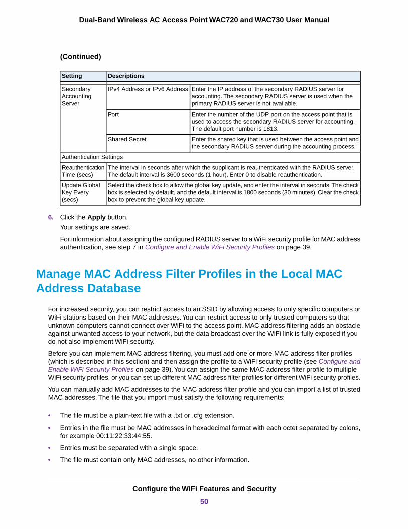
(Continued)
DescriptionsSetting
Enter the IP address of the secondary RADIUS server foraccounting. The secondary RADIUS server is used when theprimary RADIUS server is not available.
IPv4 Address or IPv6 AddressSecondaryAccountingServer
Enter the number of the UDP port on the access point that isused to access the secondary RADIUS server for accounting.The default port number is 1813.
Port
Enter the shared key that is used between the access point andthe secondary RADIUS server during the accounting process.
Shared Secret
Authentication Settings
The interval in seconds after which the supplicant is reauthenticated with the RADIUS server.The default interval is 3600 seconds (1 hour). Enter 0 to disable reauthentication.
ReauthenticationTime (secs)
Select the check box to allow the global key update, and enter the interval in seconds.The checkbox is selected by default, and the default interval is 1800 seconds (30 minutes). Clear the checkbox to prevent the global key update.
Update GlobalKey Every(secs)
6. Click the Apply button.
Your settings are saved.
For information about assigning the configured RADIUS server to a WiFi security profile for MAC addressauthentication, see step 7 in Configure and Enable WiFi Security Profiles on page 39.
Manage MAC Address Filter Profiles in the Local MACAddress Database
For increased security, you can restrict access to an SSID by allowing access to only specific computers orWiFi stations based on their MAC addresses.You can restrict access to only trusted computers so thatunknown computers cannot connect over WiFi to the access point. MAC address filtering adds an obstacleagainst unwanted access to your network, but the data broadcast over the WiFi link is fully exposed if youdo not also implement WiFi security.
Before you can implement MAC address filtering, you must add one or more MAC address filter profiles(which is described in this section) and then assign the profile to a WiFi security profile (see Configure andEnable WiFi Security Profiles on page 39).You can assign the same MAC address filter profile to multipleWiFi security profiles, or you can set up different MAC address filter profiles for different WiFi security profiles.
You can manually add MAC addresses to the MAC address filter profile and you can import a list of trustedMAC addresses. The file that you import must satisfy the following requirements:
• The file must be a plain-text file with a .txt or .cfg extension.
• Entries in the file must be MAC addresses in hexadecimal format with each octet separated by colons,for example 00:11:22:33:44:55.
• Entries must be separated with a single space.
• The file must contain only MAC addresses, no other information.
Configure the WiFi Features and Security
50
Dual-Band Wireless AC Access Point WAC720 and WAC730 User Manual
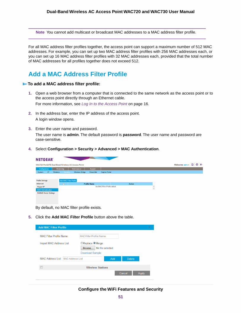
You cannot add multicast or broadcast MAC addresses to a MAC address filter profile.Note
For all MAC address filter profiles together, the access point can support a maximum number of 512 MACaddresses. For example, you can set up two MAC address filter profiles with 256 MAC addresses each, oryou can set up 16 MAC address filter profiles with 32 MAC addresses each, provided that the total numberof MAC addresses for all profiles together does not exceed 512.
Add a MAC Address Filter ProfileTo add a MAC address filter profile:
1. Open a web browser from a computer that is connected to the same network as the access point or tothe access point directly through an Ethernet cable.
For more information, see Log In to the Access Point on page 16.
2. In the address bar, enter the IP address of the access point.
A login window opens.
3. Enter the user name and password.
The user name is admin. The default password is password. The user name and password arecase-sensitive.
4. Select Configuration > Security > Advanced > MAC Authentication.
By default, no MAC filter profile exists.
5. Click the Add MAC Filter Profile button above the table.
Configure the WiFi Features and Security
51
Dual-Band Wireless AC Access Point WAC720 and WAC730 User Manual
6. In the MAC Filter Profile Name field, enter a name for the new profile.
This name identifies the profile and lets you assign it later to a WiFi security profile.
7. Populate the Wireless Stations table by one of the following methods or by a combination of the followingmethods:
• Enter MAC addresses manually by doing the following:
a. Enter a MAC address in the MAC Address List field.
b. Click the Add button.
• Import a list of trusted MAC addresses by doing the following:
a. Select the Replace radio button or Merge radio button.The imported list either replaces the MAC addresses in the Wireless Stations table or mergeswith the MAC addresses in the Wireless Stations table.
b. Click the Browse button and navigate to and select the file with MAC addresses.
The file that you import must be a plain-text file with a .txt or .cfg extension. Entries in the file must beMAC addresses in hexadecimal format with each octet separated by colons, for example00:11:22:33:44:55. Separate entries with a single space. For the file to be accepted, it must contain onlyMAC addresses.
To download a sample file, click the Download Sample link.Note
8. To fine-tune the Wireless Stations table and delete one or more MAC addresses from the WirelessStations table, select individual check boxes for the MAC addresses and click the Delete button.
9. Click the Apply button.
Your settings are saved. The Add MAC Filter Profile pop-up window closes.
For information about assigning the MAC address filter profile to a WiFi security profile, see Step 7 inConfigure and Enable WiFi Security Profiles on page 39.
Modify a MAC Address Filter ProfileTo modify an existing MAC address filter profile:
1. Open a web browser from a computer that is connected to the same network as the access point or tothe access point directly through an Ethernet cable.
For more information, see Log In to the Access Point on page 16.
2. In the address bar, enter the IP address of the access point.
A login window opens.
3. Enter the user name and password.
The user name is admin. The default password is password. The user name and password arecase-sensitive.
Configure the WiFi Features and Security
52
Dual-Band Wireless AC Access Point WAC720 and WAC730 User Manual
4. Select Configuration > Security > Advanced > MAC Authentication.
The page that displays shows a table with MAC address filter profiles.
5. If more than one profile exists, select the check box for the profile that you want to modify.
6. Click the Edit button.
The Edit MAC Filter Profile pop-up window opens.
7. Modify the MAC address filter profile.
For more information, see Add a MAC Address Filter Profile on page 51.
8. Click the Apply button.
Your settings are saved. The Add MAC Filter Profile pop-up window closes.
Delete a MAC Address Filter ProfileTo delete an existing MAC address filter profile:
1. Open a web browser from a computer that is connected to the same network as the access point or tothe access point directly through an Ethernet cable.
For more information, see Log In to the Access Point on page 16.
2. In the address bar, enter the IP address of the access point.
A login window opens.
3. Enter the user name and password.
The user name is admin. The default password is password. The user name and password arecase-sensitive.
4. Select Configuration > Security > Advanced > MAC Authentication.
The MAC Authentication page displays and shows a table with MAC address filter profiles.
5. Select the check box for the profile that you want to delete.
You can select more than one check box and delete several profiles.
6. Click the Delete Profile button.
The profile or profiles are deleted.
Enable Rogue AP Detection and Monitor Rogue APs
Unidentified access points (APs) that use the SSID of a legitimate network can present a serious securitythreat. Detecting rogue access points involves scanning the WiFi environment on all available channels,looking for unidentified access points.
When rogue AP detection is enabled, the access point interacts only with devices in the Known AP list.
Configure the WiFi Features and Security
53
Dual-Band Wireless AC Access Point WAC720 and WAC730 User Manual

Enable Rogue AP DetectionWhen you enable rogue AP detection, the access point interacts only with devices in the Known AP list.
To enable rogue AP detection:
1. Open a web browser from a computer that is connected to the same network as the access point or tothe access point directly through an Ethernet cable.
For more information, see Log In to the Access Point on page 16.
2. In the address bar, enter the IP address of the access point.
A login window opens.
3. Enter the user name and password.
The user name is admin. The default password is password. The user name and password arecase-sensitive.
4. Select Configuration > Security > Advanced > Rogue AP.
You can conrogue AP detection for 802.11 bg/ng/bgn devices, 802.11 a/a-na-ac devices, or both typesof devices.
5. Select the Turn Rogue AP Detection On check box.
6. Select a detection policy from the Rogue AP Detection Policy menu:
• Mild. The AP scans for unknown APs every 180 seconds.
• Moderate. The AP scans for unknown APs every 60 seconds.
• Aggressive. The AP scans for unknown APs every 10 seconds.
Detected rogue APs are placed in the Unknown AP List.
Configure the WiFi Features and Security
54
Dual-Band Wireless AC Access Point WAC720 and WAC730 User Manual
7. To move APs from the Unknown AP List to the Known AP List, do the following:
a. Select individual check boxes for MAC addresses, or select all MAC addresses by selecting thecheck box in the heading.
b. Click the Move button to transfer the MAC addresses from the Unknown AP List to the Known APList.
8. To import a list of known APs, do the following:
a. Click the Replace or Merge button.
The imported list either replaces the Known AP List or merges with the Known AP List.
b. Click the Choose File button and navigate to and select the file with access points.
The file that you import must be a plain-text file with a .txt or .cfg extension. Entries in the file must beMAC addresses in hexadecimal format with each octet separated by colons, for example00:11:22:33:44:55. Separate entries with a single space. For the file to be accepted, it must contain onlyMAC addresses.
9. To fine-tune the Known AP List and delete one or more MAC address from the Known AP List, selectindividual check boxes for the MAC addresses and click the Delete button.
10. Click the Apply button.
Your settings are saved.
Monitor Rogue APsYou can view a table with rogue access points that were detected.The table also provides detailed informationabout the rogue access points.
To monitor rogue APs:
1. Open a web browser from a computer that is connected to the same network as the access point or tothe access point directly through an Ethernet cable.
For more information, see Log In to the Access Point on page 16.
2. In the address bar, enter the IP address of the access point.
A login window opens.
3. Enter the user name and password.
The user name is admin. The default password is password. The user name and password arecase-sensitive.
Configure the WiFi Features and Security
55
Dual-Band Wireless AC Access Point WAC720 and WAC730 User Manual

4. Select Monitoring > Rogue AP > Unknown AP List.
The Unknown AP List shows information for each unknown device, including information about beacons.
5. To update the list, click the Refresh button.
6. To save the list as a text file, click the Save button and follow the instructions of your browser to savethe file to your computer.
Monitor Knows APsYou can view a table with known access points.The table also provides information about the known accesspoints.
To monitor known APs:
1. Open a web browser from a computer that is connected to the same network as the access point or tothe access point directly through an Ethernet cable.
For more information, see Log In to the Access Point on page 16.
2. In the address bar, enter the IP address of the access point.
A login window opens.
3. Enter the user name and password.
The user name is admin. The default password is password. The user name and password arecase-sensitive.
Configure the WiFi Features and Security
56
Dual-Band Wireless AC Access Point WAC720 and WAC730 User Manual

4. Select Monitoring > Rogue AP > Known AP List.
The Known AP List shows information for each known device.
5. To update the list, click the Refresh button.
6. To save the list as a text file, click the Save button and follow the instructions of your browser to savethe file to your computer.
Schedule the WiFi Radios to Be Turned Off
Scheduling the WiFi radios to be turned off is a green feature that allows you to turn off the WiFi radiosduring scheduled vacations, office shutdowns, on evenings, or on weekends.
The schedule applies to all WiFi networks that broadcast on a radio. For information about scheduling thebroadcast of an individual WiFi network, see step 8 in Configure and Enable WiFi Security Profiles on page39.
To schedule the radios to be turned on and off:
1. Open a web browser from a computer that is connected to the same network as the access point or tothe access point directly through an Ethernet cable.
For more information, see Log In to the Access Point on page 16.
2. In the address bar, enter the IP address of the access point.
A login window opens.
3. Enter the user name and password.
The user name is admin. The default password is password. The user name and password arecase-sensitive.
Configure the WiFi Features and Security
57
Dual-Band Wireless AC Access Point WAC720 and WAC730 User Manual

4. Select Configuration > Wireless > Basic > Wireless Scheduling.
The previous show the page for a custom scheduling type. However, by default, the page for the Everydayscheduling type displays.
You can a schedule for 802.11 bg/ng/bgn devices, 802.11 a/a-na-ac devices, or both types of devices.
5. Select the Wireless Scheduling Enable radio button.
By default, the Disable radio button is selected.
6. From the Wireless Scheduling Type menu, select one of the following options:
• Everyday. The schedule applies every day of the week (Monday through Sunday). Set the startand end time for the schedule by moving the circles on the Radio On & Off Time bar. By default,this schedule enables the radio to be active from 7:00 a.m. to 6:30 p.m. (18:30).
• Weekdays. The schedule applies every weekday of the week (that is, Monday through Friday). Setthe start and end time for the schedule by moving the circles on the Radio On & Off Time bar. Bydefault, this schedule enables the radio to be active from 7:00 a.m. to 6:30 p.m. (18:30).
• Weekend. The schedule applies on the weekend only (Saturday and Sunday). Set the start andend time for the schedule by moving the circles on the Radio On & Off Time bar. By default, thisschedule enables the radio to be active from 7:00 a.m. to 6:30 p.m. (18:30).
• Custom. This selection lets you define a schedule for each day of the week or selected days of theweek by doing the following:
Configure the WiFi Features and Security
58
Dual-Band Wireless AC Access Point WAC720 and WAC730 User Manual

a. Select the check boxes for the days for which you want to set and activate a schedule and clearthe check boxes for the days for which you do not want to set and activate a schedule.
b. For each active day, set the start and end time for the schedule by moving the circles on thebar that is associated with the individual day. By default, the schedule enables the radio to beactive from 7:00 a.m. to 6:30 p.m. (18:30) on the individual day.
7. Click the Apply button.
Your settings are saved.
The schedule is active and WiFi broadcast occurs according to the schedule that you defined.
Configure Basic WiFi Quality of Service
Wi-Fi Multimedia (WMM) is a subset of the 802.11e standard.WMM allows you to specify a range of priorities,depending on the type of data.Time-dependent information, such as video or audio, is given a higher prioritythan normal traffic. For WMM to function correctly, WiFi clients must also support WMM.
By enabling WMM, you allow Quality of Service (QoS) control for upstream traffic flowing from a WiFi stationto the access point and for downstream traffic flowing from the access point to a WiFi station.
WMM defines the following four queues in decreasing order of priority:
• Voice. The highest priority queue with minimum delay, which makes it ideal for applications like VoIPand streaming media.
• Video. The second highest priority queue with low delay is given to this queue. Video applications arerouted to this queue.
• Best Effort. The medium priority queue with medium delay is given to this queue. Most standard IPapplications use this queue.
• Background. Low priority queue with high throughput. Applications, such as FTP, that are nottime-sensitive but require high throughput can use this queue.
The WMM Powersave feature saves power for battery-powered equipment by increasing the efficiency andflexibility of data transmission.
For information about how to configure advanced WiFi QoS, that is, to configurespecific Enhanced Distributed Channel Access (EDCA) settings, see ConfigureAdvanced Quality of Service Settings on page 109.
Note
To configure basic WiFi QoS:
1. Open a web browser from a computer that is connected to the same network as the access point or tothe access point directly through an Ethernet cable.
For more information, see Log In to the Access Point on page 16.
2. In the address bar, enter the IP address of the access point.
A login window opens.
Configure the WiFi Features and Security
59
Dual-Band Wireless AC Access Point WAC720 and WAC730 User Manual

3. Enter the user name and password.
The user name is admin. The default password is password. The user name and password arecase-sensitive.
4. Select Configuration > Wireless > Basic > QoS Settings.
5. To turn on QoS globally, select the Mode Enable button.
6. Enable or disable individual WMM features for 802.11 bg/ng/bgn devices, 802.11 a/a-na-ac devices, orboth types of devices:
• Enable Wi-Fi Multimedia (WMM). To enable this feature, select the Enable radio button, which isthe default setting. Select the Disable radio button to disable the feature.
• WMM Powersave.To enable this feature, select the Enable radio button, which is the default setting.Select the Disable radio button to disable the feature.
7. Click the Apply button.
Your settings are saved.
Configure the WiFi Features and Security
60
Dual-Band Wireless AC Access Point WAC720 and WAC730 User Manual
4Manage and Monitor the Access Point
This chapter describes how to use the management and monitoring features of the access point.
The chapter includes the following sections:
• Enable Remote Management• Upgrade the Access Point Firmware• Manage the Configuration File or Reset to Factory Defaults• Change the Administrator Password• Manage User Accounts• Enable the Syslog Server• Monitor the Access Point• View the Activity Logs• View the Traffic Statistics• Set Up, Manage, and Monitor Ensembles
61
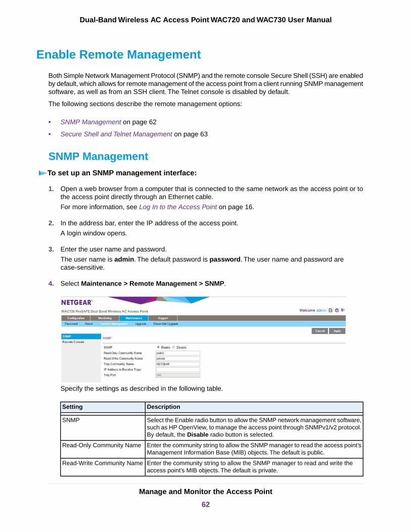
Enable Remote Management
Both Simple Network Management Protocol (SNMP) and the remote console Secure Shell (SSH) are enabledby default, which allows for remote management of the access point from a client running SNMP managementsoftware, as well as from an SSH client. The Telnet console is disabled by default.
The following sections describe the remote management options:
• SNMP Management on page 62
• Secure Shell and Telnet Management on page 63
SNMP ManagementTo set up an SNMP management interface:
1. Open a web browser from a computer that is connected to the same network as the access point or tothe access point directly through an Ethernet cable.
For more information, see Log In to the Access Point on page 16.
2. In the address bar, enter the IP address of the access point.
A login window opens.
3. Enter the user name and password.
The user name is admin. The default password is password. The user name and password arecase-sensitive.
4. Select Maintenance > Remote Management > SNMP.
Specify the settings as described in the following table.
DescriptionSetting
Select the Enable radio button to allow the SNMP network management software,such as HP OpenView, to manage the access point through SNMPv1/v2 protocol.By default, the Disable radio button is selected.
SNMP
Enter the community string to allow the SNMP manager to read the access point’sManagement Information Base (MIB) objects. The default is public.
Read-Only Community Name
Enter the community string to allow the SNMP manager to read and write theaccess point’s MIB objects. The default is private.
Read-Write Community Name
Manage and Monitor the Access Point
62
Dual-Band Wireless AC Access Point WAC720 and WAC730 User Manual
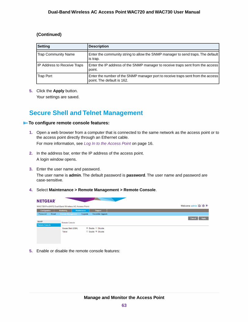
(Continued)
DescriptionSetting
Enter the community string to allow the SNMP manager to send traps.The defaultis trap.
Trap Community Name
Enter the IP address of the SNMP manager to receive traps sent from the accesspoint.
IP Address to Receive Traps
Enter the number of the SNMP manager port to receive traps sent from the accesspoint. The default is 162.
Trap Port
5. Click the Apply button.
Your settings are saved.
Secure Shell and Telnet ManagementTo configure remote console features:
1. Open a web browser from a computer that is connected to the same network as the access point or tothe access point directly through an Ethernet cable.
For more information, see Log In to the Access Point on page 16.
2. In the address bar, enter the IP address of the access point.
A login window opens.
3. Enter the user name and password.
The user name is admin. The default password is password. The user name and password arecase-sensitive.
4. Select Maintenance > Remote Management > Remote Console.
5. Enable or disable the remote console features:
Manage and Monitor the Access Point
63
Dual-Band Wireless AC Access Point WAC720 and WAC730 User Manual
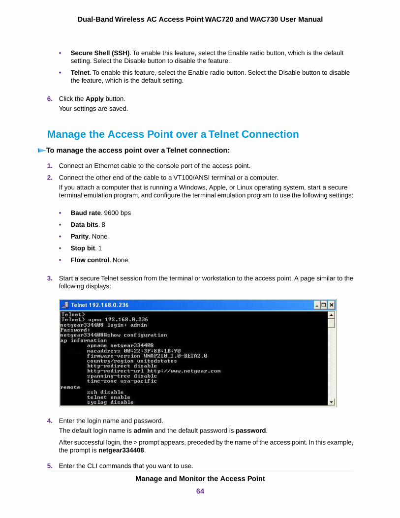
• Secure Shell (SSH). To enable this feature, select the Enable radio button, which is the defaultsetting. Select the Disable button to disable the feature.
• Telnet. To enable this feature, select the Enable radio button. Select the Disable button to disablethe feature, which is the default setting.
6. Click the Apply button.
Your settings are saved.
Manage the Access Point over a Telnet ConnectionTo manage the access point over a Telnet connection:
1. Connect an Ethernet cable to the console port of the access point.
2. Connect the other end of the cable to a VT100/ANSI terminal or a computer.
If you attach a computer that is running a Windows, Apple, or Linux operating system, start a secureterminal emulation program, and configure the terminal emulation program to use the following settings:
• Baud rate. 9600 bps
• Data bits. 8
• Parity. None
• Stop bit. 1
• Flow control. None
3. Start a secure Telnet session from the terminal or workstation to the access point. A page similar to thefollowing displays:
4. Enter the login name and password.
The default login name is admin and the default password is password.
After successful login, the > prompt appears, preceded by the name of the access point. In this example,the prompt is netgear334408.
5. Enter the CLI commands that you want to use.
Manage and Monitor the Access Point
64
Dual-Band Wireless AC Access Point WAC720 and WAC730 User Manual
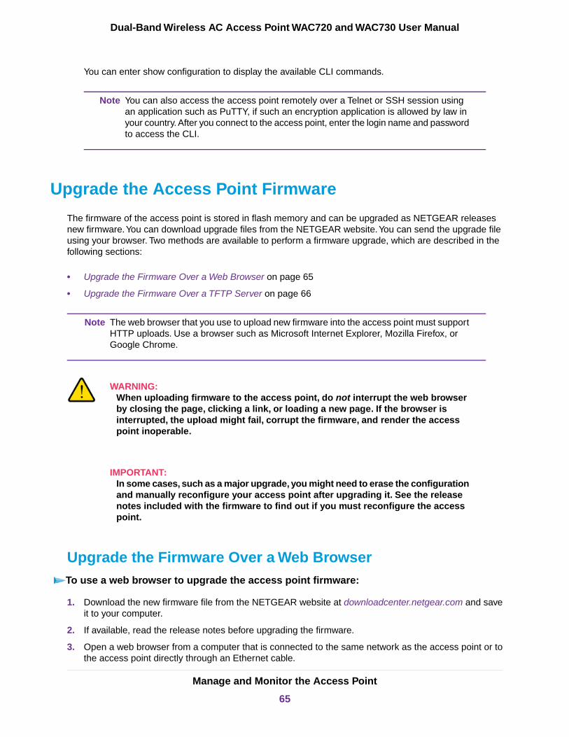
You can enter show configuration to display the available CLI commands.
You can also access the access point remotely over a Telnet or SSH session usingan application such as PuTTY, if such an encryption application is allowed by law inyour country. After you connect to the access point, enter the login name and passwordto access the CLI.
Note
Upgrade the Access Point Firmware
The firmware of the access point is stored in flash memory and can be upgraded as NETGEAR releasesnew firmware.You can download upgrade files from the NETGEAR website.You can send the upgrade fileusing your browser. Two methods are available to perform a firmware upgrade, which are described in thefollowing sections:
• Upgrade the Firmware Over a Web Browser on page 65
• Upgrade the Firmware Over a TFTP Server on page 66
The web browser that you use to upload new firmware into the access point must supportHTTP uploads. Use a browser such as Microsoft Internet Explorer, Mozilla Firefox, orGoogle Chrome.
Note
WARNING:When uploading firmware to the access point, do not interrupt the web browserby closing the page, clicking a link, or loading a new page. If the browser isinterrupted, the upload might fail, corrupt the firmware, and render the accesspoint inoperable.
IMPORTANT:In some cases, such as a major upgrade, you might need to erase the configurationand manually reconfigure your access point after upgrading it. See the releasenotes included with the firmware to find out if you must reconfigure the accesspoint.
Upgrade the Firmware Over a Web BrowserTo use a web browser to upgrade the access point firmware:
1. Download the new firmware file from the NETGEAR website at downloadcenter.netgear.com and saveit to your computer.
2. If available, read the release notes before upgrading the firmware.
3. Open a web browser from a computer that is connected to the same network as the access point or tothe access point directly through an Ethernet cable.
Manage and Monitor the Access Point
65
Dual-Band Wireless AC Access Point WAC720 and WAC730 User Manual
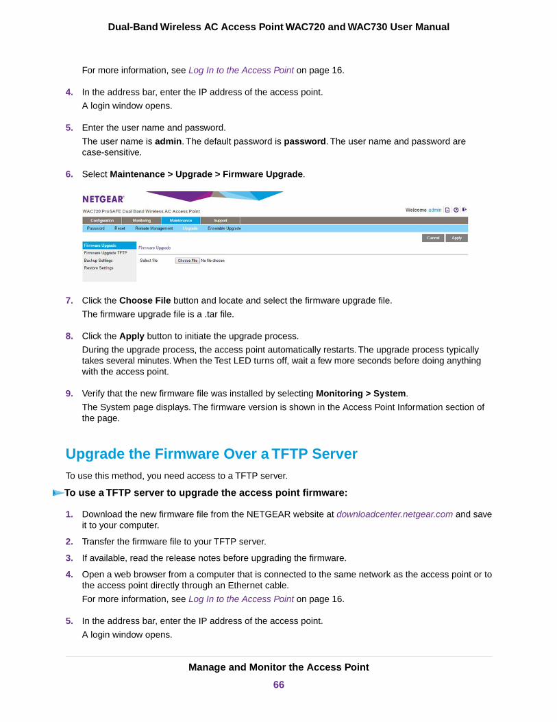
For more information, see Log In to the Access Point on page 16.
4. In the address bar, enter the IP address of the access point.
A login window opens.
5. Enter the user name and password.
The user name is admin. The default password is password. The user name and password arecase-sensitive.
6. Select Maintenance > Upgrade > Firmware Upgrade.
7. Click the Choose File button and locate and select the firmware upgrade file.
The firmware upgrade file is a .tar file.
8. Click the Apply button to initiate the upgrade process.
During the upgrade process, the access point automatically restarts. The upgrade process typicallytakes several minutes. When the Test LED turns off, wait a few more seconds before doing anythingwith the access point.
9. Verify that the new firmware file was installed by selecting Monitoring > System.
The System page displays. The firmware version is shown in the Access Point Information section ofthe page.
Upgrade the Firmware Over a TFTP ServerTo use this method, you need access to a TFTP server.
To use a TFTP server to upgrade the access point firmware:
1. Download the new firmware file from the NETGEAR website at downloadcenter.netgear.com and saveit to your computer.
2. Transfer the firmware file to your TFTP server.
3. If available, read the release notes before upgrading the firmware.
4. Open a web browser from a computer that is connected to the same network as the access point or tothe access point directly through an Ethernet cable.
For more information, see Log In to the Access Point on page 16.
5. In the address bar, enter the IP address of the access point.
A login window opens.
Manage and Monitor the Access Point
66
Dual-Band Wireless AC Access Point WAC720 and WAC730 User Manual

6. Enter the user name and password.
The user name is admin. The default password is password. The user name and password arecase-sensitive.
7. Select Maintenance > Upgrade > Firmware Upgrade TFTP.
8. Specify the following information:
• Firmware File Name. The name of the firmware file.
• TFTP Server IP. The IP address of your TFTP server.
9. Click the Apply button to initiate the upgrade process.
During the upgrade process, the access point automatically restarts. The upgrade process typicallytakes several minutes. When the Test LED turns off, wait a few more seconds before doing anythingwith the access point.
10. Verify that the new firmware file was installed by selecting Monitoring > System.
The System page displays. The firmware version is shown in the Access Point Information section ofthe page.
Manage the Configuration File or Reset to Factory Defaults
The access point settings are stored in the configuration file.You can save this file (back it up) to a computer,restore it from a computer, or reset it to factory default settings, as described in the following sections:
• Save the Configuration on page 68
• Restore the Configuration on page 68
• Restore the Access Point to the Factory Default Settings on page 69
• Reboot the Access Point Without Restoring the Default Configuration on page 71
Manage and Monitor the Access Point
67
Dual-Band Wireless AC Access Point WAC720 and WAC730 User Manual
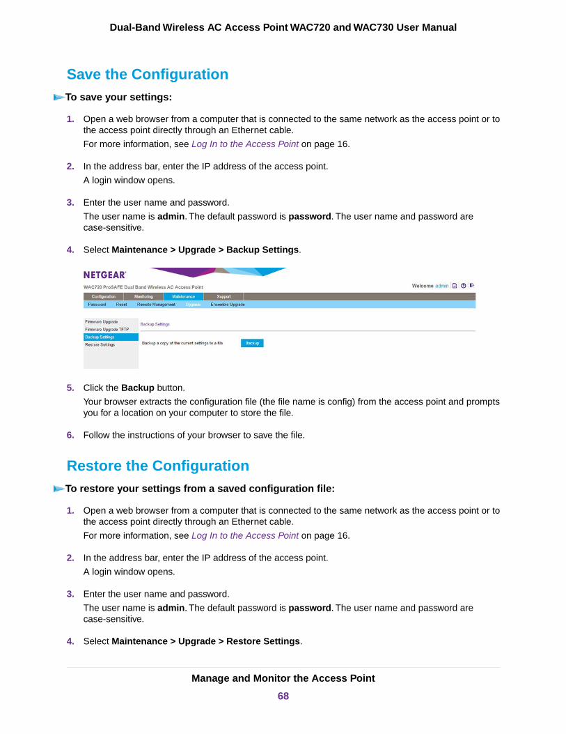
Save the ConfigurationTo save your settings:
1. Open a web browser from a computer that is connected to the same network as the access point or tothe access point directly through an Ethernet cable.
For more information, see Log In to the Access Point on page 16.
2. In the address bar, enter the IP address of the access point.
A login window opens.
3. Enter the user name and password.
The user name is admin. The default password is password. The user name and password arecase-sensitive.
4. Select Maintenance > Upgrade > Backup Settings.
5. Click the Backup button.
Your browser extracts the configuration file (the file name is config) from the access point and promptsyou for a location on your computer to store the file.
6. Follow the instructions of your browser to save the file.
Restore the ConfigurationTo restore your settings from a saved configuration file:
1. Open a web browser from a computer that is connected to the same network as the access point or tothe access point directly through an Ethernet cable.
For more information, see Log In to the Access Point on page 16.
2. In the address bar, enter the IP address of the access point.
A login window opens.
3. Enter the user name and password.
The user name is admin. The default password is password. The user name and password arecase-sensitive.
4. Select Maintenance > Upgrade > Restore Settings.
Manage and Monitor the Access Point
68
Dual-Band Wireless AC Access Point WAC720 and WAC730 User Manual
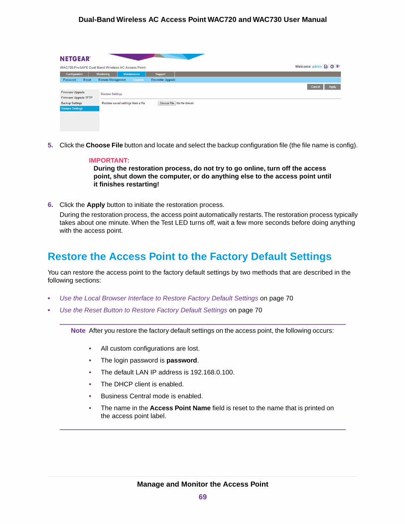
5. Click the Choose File button and locate and select the backup configuration file (the file name is config).
IMPORTANT:During the restoration process, do not try to go online, turn off the accesspoint, shut down the computer, or do anything else to the access point untilit finishes restarting!
6. Click the Apply button to initiate the restoration process.
During the restoration process, the access point automatically restarts.The restoration process typicallytakes about one minute. When the Test LED turns off, wait a few more seconds before doing anythingwith the access point.
Restore the Access Point to the Factory Default SettingsYou can restore the access point to the factory default settings by two methods that are described in thefollowing sections:
• Use the Local Browser Interface to Restore Factory Default Settings on page 70
• Use the Reset Button to Restore Factory Default Settings on page 70
After you restore the factory default settings on the access point, the following occurs:Note
• All custom configurations are lost.
• The login password is password.
• The default LAN IP address is 192.168.0.100.
• The DHCP client is enabled.
• Business Central mode is enabled.
• The name in the Access Point Name field is reset to the name that is printed onthe access point label.
Manage and Monitor the Access Point
69
Dual-Band Wireless AC Access Point WAC720 and WAC730 User Manual
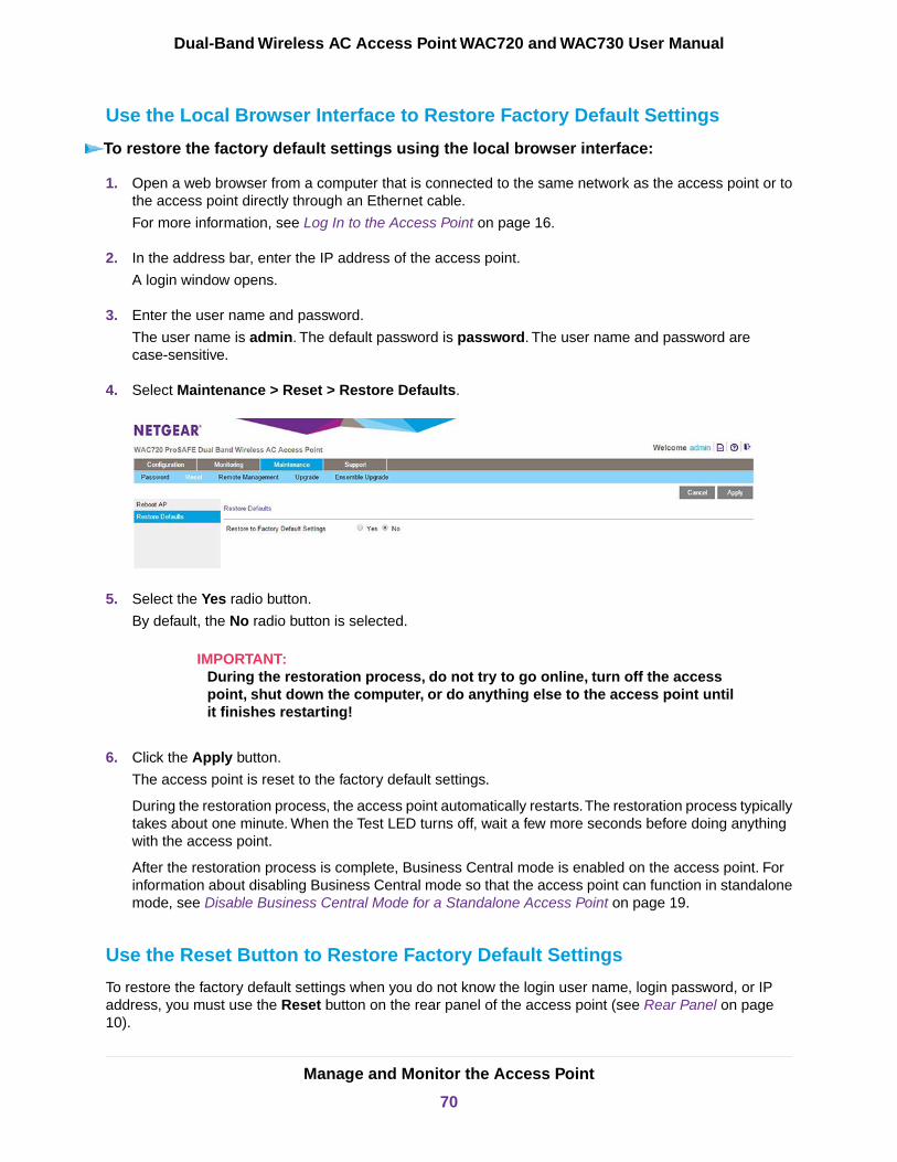
Use the Local Browser Interface to Restore Factory Default Settings
To restore the factory default settings using the local browser interface:
1. Open a web browser from a computer that is connected to the same network as the access point or tothe access point directly through an Ethernet cable.
For more information, see Log In to the Access Point on page 16.
2. In the address bar, enter the IP address of the access point.
A login window opens.
3. Enter the user name and password.
The user name is admin. The default password is password. The user name and password arecase-sensitive.
4. Select Maintenance > Reset > Restore Defaults.
5. Select the Yes radio button.
By default, the No radio button is selected.
IMPORTANT:During the restoration process, do not try to go online, turn off the accesspoint, shut down the computer, or do anything else to the access point untilit finishes restarting!
6. Click the Apply button.
The access point is reset to the factory default settings.
During the restoration process, the access point automatically restarts.The restoration process typicallytakes about one minute. When the Test LED turns off, wait a few more seconds before doing anythingwith the access point.
After the restoration process is complete, Business Central mode is enabled on the access point. Forinformation about disabling Business Central mode so that the access point can function in standalonemode, see Disable Business Central Mode for a Standalone Access Point on page 19.
Use the Reset Button to Restore Factory Default Settings
To restore the factory default settings when you do not know the login user name, login password, or IPaddress, you must use the Reset button on the rear panel of the access point (see Rear Panel on page10).
Manage and Monitor the Access Point
70
Dual-Band Wireless AC Access Point WAC720 and WAC730 User Manual
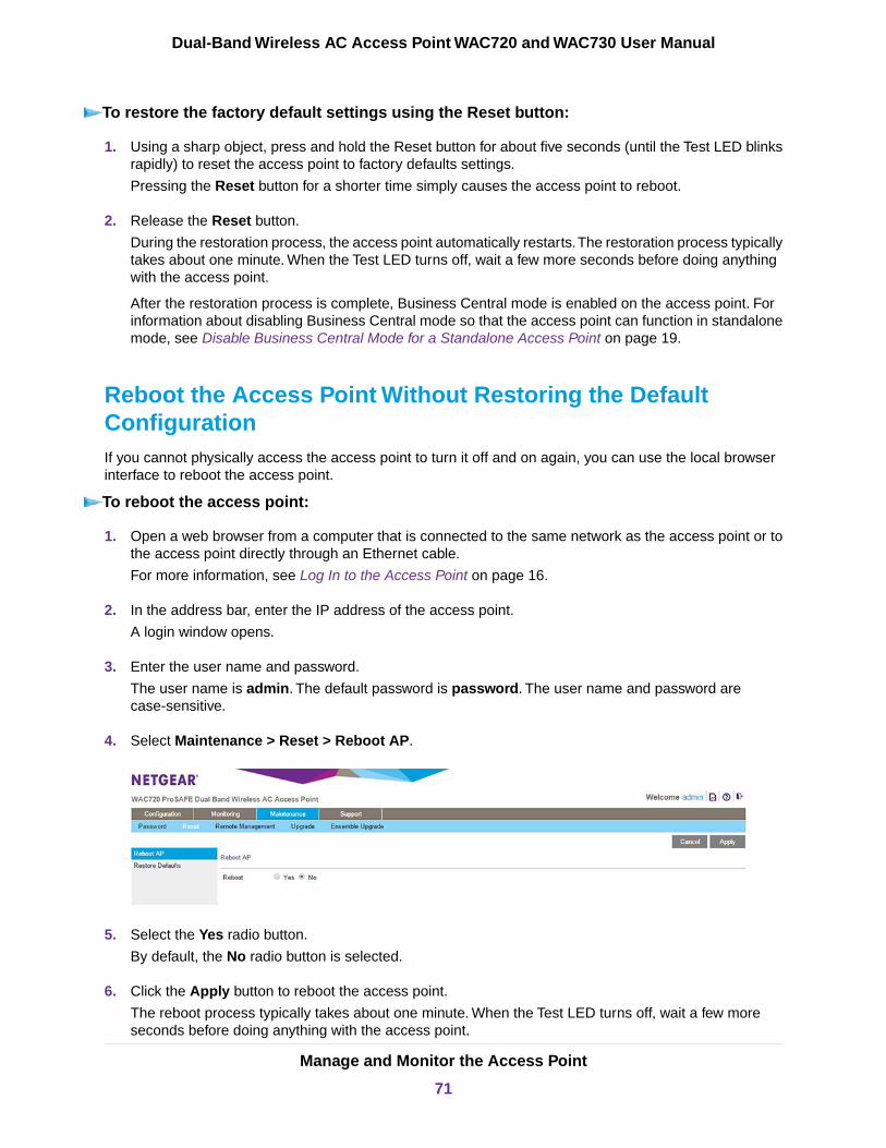
To restore the factory default settings using the Reset button:
1. Using a sharp object, press and hold the Reset button for about five seconds (until the Test LED blinksrapidly) to reset the access point to factory defaults settings.
Pressing the Reset button for a shorter time simply causes the access point to reboot.
2. Release the Reset button.
During the restoration process, the access point automatically restarts.The restoration process typicallytakes about one minute. When the Test LED turns off, wait a few more seconds before doing anythingwith the access point.
After the restoration process is complete, Business Central mode is enabled on the access point. Forinformation about disabling Business Central mode so that the access point can function in standalonemode, see Disable Business Central Mode for a Standalone Access Point on page 19.
Reboot the Access Point Without Restoring the DefaultConfigurationIf you cannot physically access the access point to turn it off and on again, you can use the local browserinterface to reboot the access point.
To reboot the access point:
1. Open a web browser from a computer that is connected to the same network as the access point or tothe access point directly through an Ethernet cable.
For more information, see Log In to the Access Point on page 16.
2. In the address bar, enter the IP address of the access point.
A login window opens.
3. Enter the user name and password.
The user name is admin. The default password is password. The user name and password arecase-sensitive.
4. Select Maintenance > Reset > Reboot AP.
5. Select the Yes radio button.
By default, the No radio button is selected.
6. Click the Apply button to reboot the access point.
The reboot process typically takes about one minute. When the Test LED turns off, wait a few moreseconds before doing anything with the access point.
Manage and Monitor the Access Point
71
Dual-Band Wireless AC Access Point WAC720 and WAC730 User Manual

Change the Administrator Password
The default password is password. We recommend that you change this password to a more securepassword.You cannot change the administrator login name (admin).
The ideal password contains no dictionary words from any language and is a mixture of letters (both uppercaseand lowercase), numbers, and symbols.Your password can be up to 30 characters.
To change the administrator password:
1. Open a web browser from a computer that is connected to the same network as the access point or tothe access point directly through an Ethernet cable.
For more information, see Log In to the Access Point on page 16.
2. In the address bar, enter the IP address of the access point.
A login window opens.
3. Enter the user name and password.
The user name is admin. The default password is password. The user name and password arecase-sensitive.
4. Select Maintenance > Password > Change Password.
5. Take one of the following actions:
• Enter a new password twice, once in the New Password field and again in the Repeat NewPassword field.
• To restore the default password, select the Restore Default Password Yes radio button.
By default, the No radio button is selected.
6. Click the Apply button.
Your settings are saved.
If you restored the default password, the login password is password. If you configured a new password,write it down in a secure place.
Manage and Monitor the Access Point
72
Dual-Band Wireless AC Access Point WAC720 and WAC730 User Manual
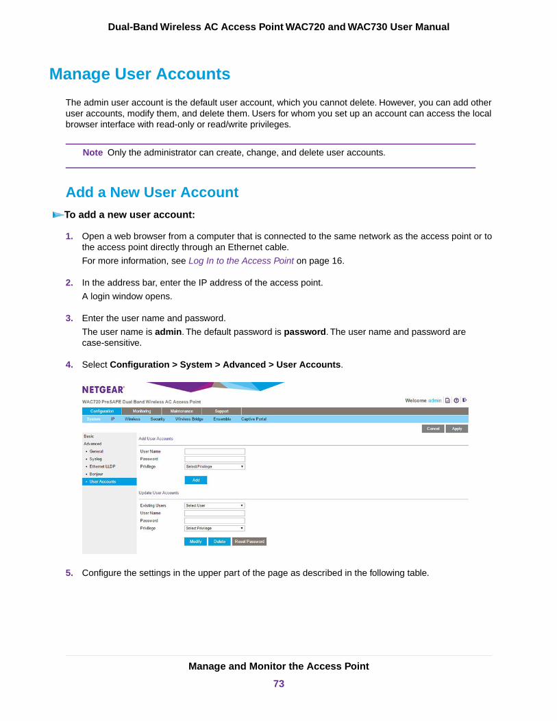
Manage User Accounts
The admin user account is the default user account, which you cannot delete. However, you can add otheruser accounts, modify them, and delete them. Users for whom you set up an account can access the localbrowser interface with read-only or read/write privileges.
Only the administrator can create, change, and delete user accounts.Note
Add a New User AccountTo add a new user account:
1. Open a web browser from a computer that is connected to the same network as the access point or tothe access point directly through an Ethernet cable.
For more information, see Log In to the Access Point on page 16.
2. In the address bar, enter the IP address of the access point.
A login window opens.
3. Enter the user name and password.
The user name is admin. The default password is password. The user name and password arecase-sensitive.
4. Select Configuration > System > Advanced > User Accounts.
5. Configure the settings in the upper part of the page as described in the following table.
Manage and Monitor the Access Point
73
Dual-Band Wireless AC Access Point WAC720 and WAC730 User Manual
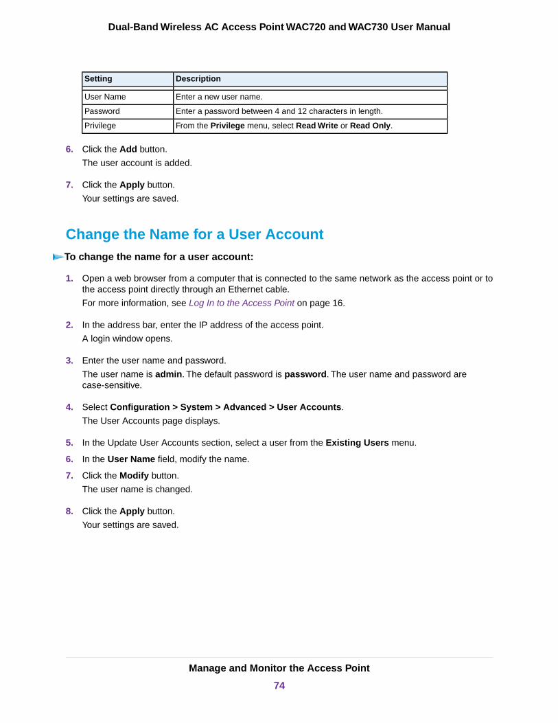
DescriptionSetting
Enter a new user name.User Name
Enter a password between 4 and 12 characters in length.Password
From the Privilege menu, select Read Write or Read Only.Privilege
6. Click the Add button.
The user account is added.
7. Click the Apply button.
Your settings are saved.
Change the Name for a User AccountTo change the name for a user account:
1. Open a web browser from a computer that is connected to the same network as the access point or tothe access point directly through an Ethernet cable.
For more information, see Log In to the Access Point on page 16.
2. In the address bar, enter the IP address of the access point.
A login window opens.
3. Enter the user name and password.
The user name is admin. The default password is password. The user name and password arecase-sensitive.
4. Select Configuration > System > Advanced > User Accounts.
The User Accounts page displays.
5. In the Update User Accounts section, select a user from the Existing Users menu.
6. In the User Name field, modify the name.
7. Click the Modify button.
The user name is changed.
8. Click the Apply button.
Your settings are saved.
Manage and Monitor the Access Point
74
Dual-Band Wireless AC Access Point WAC720 and WAC730 User Manual

Change the Privilege for a User AccountTo change the privilege for a user account:
1. Open a web browser from a computer that is connected to the same network as the access point or tothe access point directly through an Ethernet cable.
For more information, see Log In to the Access Point on page 16.
2. In the address bar, enter the IP address of the access point.
A login window opens.
3. Enter the user name and password.
The user name is admin. The default password is password. The user name and password arecase-sensitive.
4. Select Configuration > System > Advanced > User Accounts.
The User Accounts page displays.
5. In the Update User Accounts section, select a user from the Existing Users menu.
6. From the Privilege menu, select another privilege.
7. Click the Reset Password button.
The password is reset to the default password, which is password.
8. Click the Apply button.
Your settings are saved.
Reset the Password for a User AccountTo reset the password for a user account:
1. Open a web browser from a computer that is connected to the same network as the access point or tothe access point directly through an Ethernet cable.
For more information, see Log In to the Access Point on page 16.
2. In the address bar, enter the IP address of the access point.
A login window opens.
3. Enter the user name and password.
The user name is admin. The default password is password. The user name and password arecase-sensitive.
4. Select Configuration > System > Advanced > User Accounts.
The User Accounts page displays.
5. In the Update User Accounts section, select a user from the Existing Users menu.
6. Click the Reset Password button.
Manage and Monitor the Access Point
75
Dual-Band Wireless AC Access Point WAC720 and WAC730 User Manual

The password is reset to the default password, which is password.
7. Click the Apply button.
Your settings are saved.
If you want to modify a password, delete the user account, and then recreate the useraccount with the password of your choice.
Note
Delete a User AccountTo delete a user account:
1. Open a web browser from a computer that is connected to the same network as the access point or tothe access point directly through an Ethernet cable.
For more information, see Log In to the Access Point on page 16.
2. In the address bar, enter the IP address of the access point.
A login window opens.
3. Enter the user name and password.
The user name is admin. The default password is password. The user name and password arecase-sensitive.
4. Select Configuration > System > Advanced > User Accounts.
The User Accounts page displays.
5. In the Update User Accounts section, select a user from the Existing Users menu.
6. Click the Delete button.
7. Click the Apply button.
Your settings are saved.
Enable the Syslog Server
You can enable the syslog option if your LAN includes a syslog server. If syslog is enabled, the access pointsends its syslog files to the syslog server.
To enable a syslog server:
1. Open a web browser from a computer that is connected to the same network as the access point or tothe access point directly through an Ethernet cable.
For more information, see Log In to the Access Point on page 16.
2. In the address bar, enter the IP address of the access point.
A login window opens.
3. Enter the user name and password.
Manage and Monitor the Access Point
76
Dual-Band Wireless AC Access Point WAC720 and WAC730 User Manual
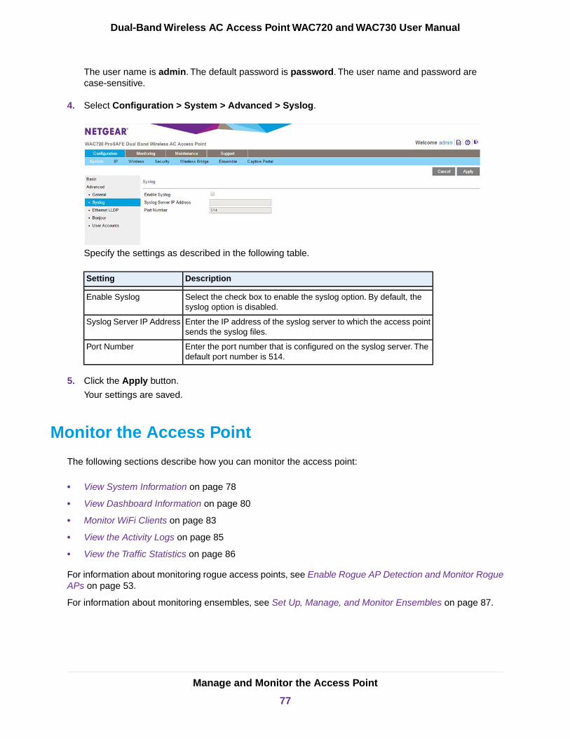
The user name is admin. The default password is password. The user name and password arecase-sensitive.
4. Select Configuration > System > Advanced > Syslog.
Specify the settings as described in the following table.
DescriptionSetting
Select the check box to enable the syslog option. By default, thesyslog option is disabled.
Enable Syslog
Enter the IP address of the syslog server to which the access pointsends the syslog files.
Syslog Server IP Address
Enter the port number that is configured on the syslog server. Thedefault port number is 514.
Port Number
5. Click the Apply button.
Your settings are saved.
Monitor the Access Point
The following sections describe how you can monitor the access point:
• View System Information on page 78
• View Dashboard Information on page 80
• Monitor WiFi Clients on page 83
• View the Activity Logs on page 85
• View the Traffic Statistics on page 86
For information about monitoring rogue access points, see Enable Rogue AP Detection and Monitor RogueAPs on page 53.
For information about monitoring ensembles, see Set Up, Manage, and Monitor Ensembles on page 87.
Manage and Monitor the Access Point
77
Dual-Band Wireless AC Access Point WAC720 and WAC730 User Manual
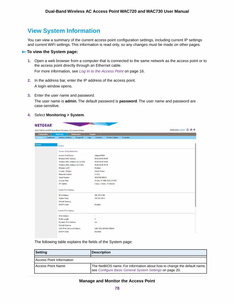
View System InformationYou can view a summary of the current access point configuration settings, including current IP settingsand current WiFi settings. This information is read only, so any changes must be made on other pages.
To view the System page:
1. Open a web browser from a computer that is connected to the same network as the access point or tothe access point directly through an Ethernet cable.
For more information, see Log In to the Access Point on page 16.
2. In the address bar, enter the IP address of the access point.
A login window opens.
3. Enter the user name and password.
The user name is admin. The default password is password. The user name and password arecase-sensitive.
4. Select Monitoring > System.
The following table explains the fields of the System page:
DescriptionSetting
Access Point Information
The NetBIOS name. For information about how to change the default name,see Configure Basic General System Settings on page 20.
Access Point Name
Manage and Monitor the Access Point
78
Dual-Band Wireless AC Access Point WAC720 and WAC730 User Manual
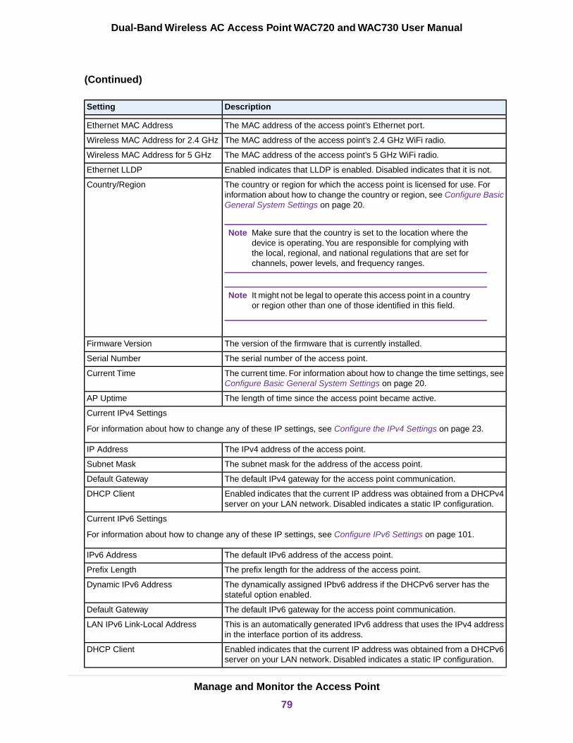
(Continued)
DescriptionSetting
The MAC address of the access point’s Ethernet port.Ethernet MAC Address
The MAC address of the access point’s 2.4 GHz WiFi radio.Wireless MAC Address for 2.4 GHz
The MAC address of the access point’s 5 GHz WiFi radio.Wireless MAC Address for 5 GHz
Enabled indicates that LLDP is enabled. Disabled indicates that it is not.Ethernet LLDP
The country or region for which the access point is licensed for use. Forinformation about how to change the country or region, see Configure BasicGeneral System Settings on page 20.
Make sure that the country is set to the location where thedevice is operating.You are responsible for complying withthe local, regional, and national regulations that are set forchannels, power levels, and frequency ranges.
Note
It might not be legal to operate this access point in a countryor region other than one of those identified in this field.
Note
Country/Region
The version of the firmware that is currently installed.Firmware Version
The serial number of the access point.Serial Number
The current time. For information about how to change the time settings, seeConfigure Basic General System Settings on page 20.
Current Time
The length of time since the access point became active.AP Uptime
Current IPv4 Settings
For information about how to change any of these IP settings, see Configure the IPv4 Settings on page 23.
The IPv4 address of the access point.IP Address
The subnet mask for the address of the access point.Subnet Mask
The default IPv4 gateway for the access point communication.Default Gateway
Enabled indicates that the current IP address was obtained from a DHCPv4server on your LAN network. Disabled indicates a static IP configuration.
DHCP Client
Current IPv6 Settings
For information about how to change any of these IP settings, see Configure IPv6 Settings on page 101.
The default IPv6 address of the access point.IPv6 Address
The prefix length for the address of the access point.Prefix Length
The dynamically assigned IPbv6 address if the DHCPv6 server has thestateful option enabled.
Dynamic IPv6 Address
The default IPv6 gateway for the access point communication.Default Gateway
This is an automatically generated IPv6 address that uses the IPv4 addressin the interface portion of its address.
LAN IPv6 Link-Local Address
Enabled indicates that the current IP address was obtained from a DHCPv6server on your LAN network. Disabled indicates a static IP configuration.
DHCP Client
Manage and Monitor the Access Point
79
Dual-Band Wireless AC Access Point WAC720 and WAC730 User Manual

(Continued)
DescriptionSetting
Current Wireless Settings for 802.11 bg/ng/bgn
and
Current Wireless Settings for 802.11 a/a-na-ac
The WiFi operation mode of the access point for the radio band. By default,the mode is 11bgn for the 2.4 GHz radio band and 11a-na-ac for the 5 GHzradio band.
Access Point Mode
The channel that the WiFi port is using. For information about how to changethe channel and frequency, see Configure 802.11bg/ng/bgn WiFi Settingson page 24 and Configure 802.11a/a-na-ac WiFi Settings on page 27.
Channel / Frequency
Enabled indicates that rogue AP detection is enabled. Disabled indicatesthat it is not.
Rogue AP Detection
View Dashboard InformationThe Dashboard pages provide general information about the access point in standalone mode or ensemblemode. In addition, the pages provide real-time and historical information about client distribution, trafficdistribution and WLAN utilization.
View the Standalone Dashboard
The Dashboard page for a standalone access point provides read-only information, so any changes mustbe made on other pages.
To view the standalone Dashboard:
1. Open a web browser from a computer that is connected to the same network as the access point or tothe access point directly through an Ethernet cable.
For more information, see Log In to the Access Point on page 16.
2. In the address bar, enter the IP address of the access point.
A login window opens.
3. Enter the user name and password.
The user name is admin. The default password is password. The user name and password arecase-sensitive.
4. Select Monitoring > Dashboard.
The Dashboard page displays.
5. Click the Stand-Alone button.
The Dashboard page displays information for the standalone access point.
Manage and Monitor the Access Point
80
Dual-Band Wireless AC Access Point WAC720 and WAC730 User Manual

6. To view more information, point to a graph.
7. To view real-time information for 5 GHz clients and traffic, click the 5 GHz button.
By default, the 2.4 GHz button is selected.
8. To view historical traffic information, click the Traffic button.
By default, the Clients button is selected.
9. To view historical information for another period, select the period from the menu below the Clients andTraffic buttons.
View the Ensemble Dashboard
The Dashboard page for an access point in ensemble mode provides read-only information, so any changesmust be made on other pages.
To view the ensemble Dashboard:
1. Open a web browser from a computer that is connected to the same network as the access point or tothe access point directly through an Ethernet cable.
For more information, see Log In to the Access Point on page 16.
2. In the address bar, enter the IP address of the access point.
A login window opens.
3. Enter the user name and password.
The user name is admin. The default password is password. The user name and password arecase-sensitive.
Manage and Monitor the Access Point
81
Dual-Band Wireless AC Access Point WAC720 and WAC730 User Manual
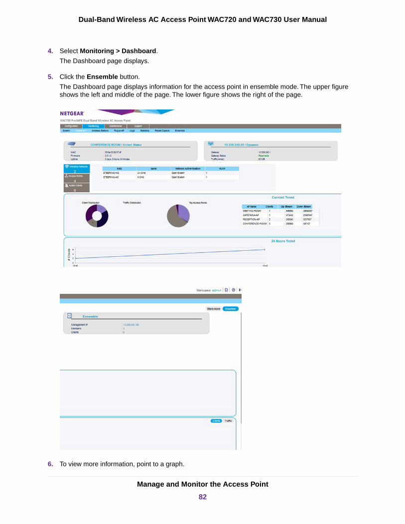
4. Select Monitoring > Dashboard.
The Dashboard page displays.
5. Click the Ensemble button.
The Dashboard page displays information for the access point in ensemble mode. The upper figureshows the left and middle of the page. The lower figure shows the right of the page.
6. To view more information, point to a graph.
Manage and Monitor the Access Point
82
Dual-Band Wireless AC Access Point WAC720 and WAC730 User Manual
7. To view historical traffic information for the past 24 hours, click the Traffic button in the lower right ofthe page.
By default, the Clients button is selected and the page shows historical client information.
8. To view details about access point in the ensemble, click the Access Points box on the left.
By default, the Wireless Networks box is selected.
9. To view details about active clients in the ensemble, click the Active Clients box on the left.
Monitor WiFi ClientsYou can view all WiFi devices that are associated with a WiFi network name (SSID) on the access point.
A WiFi network can include multiple access points, all using the same SSID. Thisuniformity extends the reach of the WiFi network and allows users to roam from oneaccess point to another, providing seamless network connectivity. Under thesecircumstances, be aware that the WiFi clients that you can monitor as described inthe following procedure are the clients that are associated with this access point.
Note
To view the attached WiFi clients and details for an individual WiFi client:
1. Open a web browser from a computer that is connected to the same network as the access point or tothe access point directly through an Ethernet cable.
For more information, see Log In to the Access Point on page 16.
2. In the address bar, enter the IP address of the access point.
A login window opens.
3. Enter the user name and password.
The user name is admin. The default password is password. The user name and password arecase-sensitive.
Manage and Monitor the Access Point
83
Dual-Band Wireless AC Access Point WAC720 and WAC730 User Manual
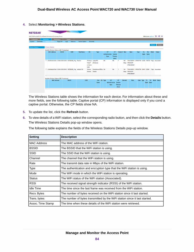
4. Select Monitoring > Wireless Stations.
The Wireless Stations table shows the information for each device. For information about these andmore fields, see the following table. Captive portal (CP) information is displayed only if you cond acaptive portal. Otherwise, the CP fields show NA.
5. To update the list, click the Refresh button.
6. To view details of a WiFi station, select the corresponding radio button, and then click the Details button.
The Wireless Stations Details pop-up window opens.
The following table explains the fields of the Wireless Stations Details pop-up window.
DescriptionSetting
The MAC address of the WiFi station.MAC Address
The BSSID that the WiFi station is using.BSSID
The SSID that the WiFi station is using.SSID
The channel that the WiFi station is using.Channel
The transmit data rate in Mbps of the WiFi station.Rate
The authentication and encryption type that the WiFi station is using.Type
The WiFi mode in which the WiFi station is operating.Mode
The WiFi status of the WiFi station (Associated).Status
The received signal strength indicator (RSSI) of the WiFi station.RSSI
The time since the last frame was received from the WiFi station.Idle Time
The number of bytes received on the WiFi station since it last started.Recv. Bytes
The number of bytes transmitted by the WiFi station since it last started.Trans. bytes
The time when these details of the WiFi station were retrieved.Assoc. Time Stamp
Manage and Monitor the Access Point
84
Dual-Band Wireless AC Access Point WAC720 and WAC730 User Manual

(Continued)
DescriptionSetting
The IP address of the WiFi station.IP Address
The channel width at which the WiFi station operates.Channel Width
View the Activity Logs
You can view the access point’s activity logs and save the log entries.
To display the activity logs and save the log entries:
1. Open a web browser from a computer that is connected to the same network as the access point or tothe access point directly through an Ethernet cable.
For more information, see Log In to the Access Point on page 16.
2. In the address bar, enter the IP address of the access point.
A login window opens.
3. Enter the user name and password.
The user name is admin. The default password is password. The user name and password arecase-sensitive.
4. Select Monitoring > Logs.
5. Click the Save As button to save the log entries to a file on your computer or to a disk drive.
6. To update the information on the page, click the Refresh button.
7. To clear the log entries, click the Clear button.
Manage and Monitor the Access Point
85
Dual-Band Wireless AC Access Point WAC720 and WAC730 User Manual
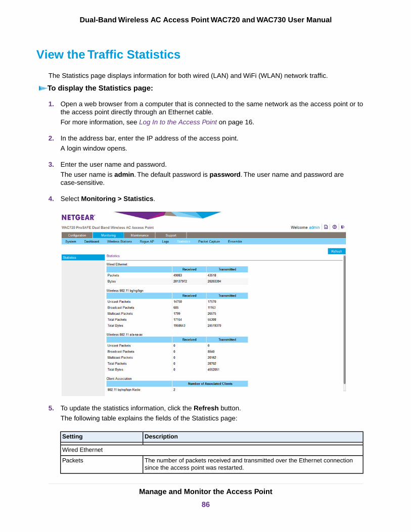
View the Traffic Statistics
The Statistics page displays information for both wired (LAN) and WiFi (WLAN) network traffic.
To display the Statistics page:
1. Open a web browser from a computer that is connected to the same network as the access point or tothe access point directly through an Ethernet cable.
For more information, see Log In to the Access Point on page 16.
2. In the address bar, enter the IP address of the access point.
A login window opens.
3. Enter the user name and password.
The user name is admin. The default password is password. The user name and password arecase-sensitive.
4. Select Monitoring > Statistics.
5. To update the statistics information, click the Refresh button.
The following table explains the fields of the Statistics page:
DescriptionSetting
Wired Ethernet
The number of packets received and transmitted over the Ethernet connectionsince the access point was restarted.
Packets
Manage and Monitor the Access Point
86
Dual-Band Wireless AC Access Point WAC720 and WAC730 User Manual

(Continued)
DescriptionSetting
The number of bytes received and transmitted over the Ethernet connection sincethe access point was restarted.
Bytes
Wireless 802.11bgn
and
Wireless 802.11a-na-ac
(The section heading depends on the configured WiFi mode.)
The number of unicast packets received and transmitted over the WiFi connectionsince the access point was restarted.
Unicast Packets
The number of broadcast packets received and transmitted over the WiFi connectionsince the access point was restarted.
Broadcast Packets
The number of multicast packets received and transmitted over the WiFi connectionsince the access point was restarted.
Multicast Packets
The total number of packets received and transmitted over the WiFi connectionsince the access point was restarted.
Total Packets
The total number of bytes received and transmitted over the WiFi connection sincethe access point was restarted.
Total Bytes
Client Association
The number of associated clients connected to the radio in the configured WiFimodes.
802.11bgn Radio,
802.11a-na-ac Radio
Set Up, Manage, and Monitor Ensembles
An access point (AP) ensemble is a dynamic, configuration-aware group of APs in the same subnet of anetwork. Each ensemble can include up to 10 members, which must be of the same model. Only oneensemble per WiFi network is supported. However, a network subnet can include multiple ensembles.Ensembles allow APs to share various configuration information, such as virtual AP (VAP) settings and QoSqueue parameters. Ensemble members share the configuration of the master AP (also referred to as thedominant AP).
With ensemble mode enabled, you can initiate common firmware updates and use a centralized ensembledashboard to monitor client connectivity and share of traffic across the ensemble members. If an ensemblemember fails, the ensemble automatically makes adjustments to ensure that the remaining members workcooperatively.
An ensemble can be formed between two more APs if the following conditions are met:
• The APs are of the same model, with the exception of model WAC720 and model WAC730, which youcan combine in an ensemble.
• The APs use the same country or region settings and the same radio mode.
• The APs are connected on the same bridged segment.
Manage and Monitor the Access Point
87
Dual-Band Wireless AC Access Point WAC720 and WAC730 User Manual

• The ensemble names of the APs that are joining are the same.
• Ensemble mode is enabled on all APs.
Configure Enable Ensemble ModeTo configure enable ensemble mode on the access point:
1. Open a web browser from a computer that is connected to the same network as the access point or tothe access point directly through an Ethernet cable.
For more information, see Log In to the Access Point on page 16.
2. In the address bar, enter the IP address of the access point.
A login window opens.
3. Enter the user name and password.
The user name is admin. The default password is password. The user name and password arecase-sensitive.
4. Select Configuration > Ensemble > Basic > General.
5. In the Ensemble Name field, enter the ensemble name.
6. In the AP Name field, enter a custom name for the access point or use the default name.
7. In the Priority (0 - 255) field, enter the access point’s priority in the ensemble.
The lowest-numbered AP becomes the master AP.
8. To enable ensemble mode, select the Start radio button.
9. Click the Apply button.
Your settings are saved.
Manage an EnsembleYou can manage an ensemble through the master access point’s local browser interface or you can specifya computer with an IP address in the same subnet as the management IP address. Through the masteraccess point or management IP address you can run an ensemble’s channel assignment, manage anensemble’s channel assignment settings, manage the firmware upgrade settings, and manage securitysettings.
Manage and Monitor the Access Point
88
Dual-Band Wireless AC Access Point WAC720 and WAC730 User Manual
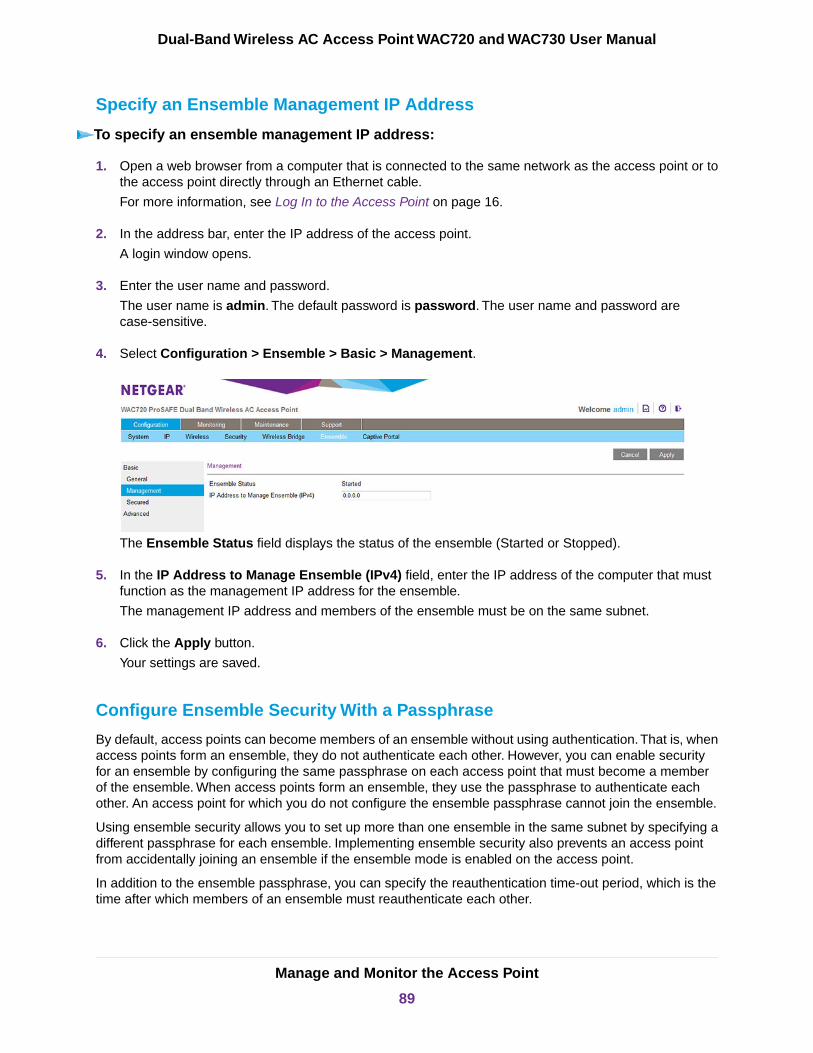
Specify an Ensemble Management IP Address
To specify an ensemble management IP address:
1. Open a web browser from a computer that is connected to the same network as the access point or tothe access point directly through an Ethernet cable.
For more information, see Log In to the Access Point on page 16.
2. In the address bar, enter the IP address of the access point.
A login window opens.
3. Enter the user name and password.
The user name is admin. The default password is password. The user name and password arecase-sensitive.
4. Select Configuration > Ensemble > Basic > Management.
The Ensemble Status field displays the status of the ensemble (Started or Stopped).
5. In the IP Address to Manage Ensemble (IPv4) field, enter the IP address of the computer that mustfunction as the management IP address for the ensemble.
The management IP address and members of the ensemble must be on the same subnet.
6. Click the Apply button.
Your settings are saved.
Configure Ensemble Security With a Passphrase
By default, access points can become members of an ensemble without using authentication.That is, whenaccess points form an ensemble, they do not authenticate each other. However, you can enable securityfor an ensemble by configuring the same passphrase on each access point that must become a memberof the ensemble. When access points form an ensemble, they use the passphrase to authenticate eachother. An access point for which you do not configure the ensemble passphrase cannot join the ensemble.
Using ensemble security allows you to set up more than one ensemble in the same subnet by specifying adifferent passphrase for each ensemble. Implementing ensemble security also prevents an access pointfrom accidentally joining an ensemble if the ensemble mode is enabled on the access point.
In addition to the ensemble passphrase, you can specify the reauthentication time-out period, which is thetime after which members of an ensemble must reauthenticate each other.
Manage and Monitor the Access Point
89
Dual-Band Wireless AC Access Point WAC720 and WAC730 User Manual

To configure security settings with a passphrase for an ensemble:
1. Open a web browser from a computer that is connected to the same network as the access point or tothe access point directly through an Ethernet cable.
For more information, see Log In to the Access Point on page 16.
2. In the address bar, enter the IP address of the access point.
A login window opens.
3. Enter the user name and password.
The user name is admin. The default password is password. The user name and password arecase-sensitive.
4. Select Configuration > Ensemble > Basic > Secured Ensemble.
5. Select the Enabled radio button.
6. Enter a passphrase between 8 and 63 characters in the passphrase field.
7. Enter a time-out period between 300 and 86400 seconds.
The default is 300 seconds.
8. Click the Apply button.
Your settings are saved.
Specify an Ensemble’s Channel Assignment Settings
Before you enable automatic channel assignment for an ensemble (see Manage Automatic ChannelAssignment for an Ensemble on page 91), you might want to specify a custom channel interference limit,which triggers channel reassignment.You can also specify the channel selection interval, which determinesthe schedule at which automatic channel assignment occurs.
The defaults are as follows:
• Channel interference limit. 75 percent (the range is from 5 percent to 75 percent).
• Channel selection interval. 1 day (the range is from 30 minutes to 6 months).
Manage and Monitor the Access Point
90
Dual-Band Wireless AC Access Point WAC720 and WAC730 User Manual
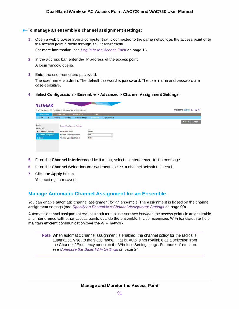
To manage an ensemble’s channel assignment settings:
1. Open a web browser from a computer that is connected to the same network as the access point or tothe access point directly through an Ethernet cable.
For more information, see Log In to the Access Point on page 16.
2. In the address bar, enter the IP address of the access point.
A login window opens.
3. Enter the user name and password.
The user name is admin. The default password is password. The user name and password arecase-sensitive.
4. Select Configuration > Ensemble > Advanced > Channel Assignment Settings.
5. From the Channel Interference Limit menu, select an interference limit percentage.
6. From the Channel Selection Interval menu, select a channel selection interval.
7. Click the Apply button.
Your settings are saved.
Manage Automatic Channel Assignment for an Ensemble
You can enable automatic channel assignment for an ensemble. The assignment is based on the channelassignment settings (see Specify an Ensemble’s Channel Assignment Settings on page 90).
Automatic channel assignment reduces both mutual interference between the access points in an ensembleand interference with other access points outside the ensemble. It also maximizes WiFi bandwidth to helpmaintain efficient communication over the WiFi network.
When automatic channel assignment is enabled, the channel policy for the radios isautomatically set to the static mode. That is, Auto is not available as a selection fromthe Channel / Frequency menu on the Wireless Settings page. For more information,see Configure the Basic WiFi Settings on page 24.
Note
Manage and Monitor the Access Point
91
Dual-Band Wireless AC Access Point WAC720 and WAC730 User Manual
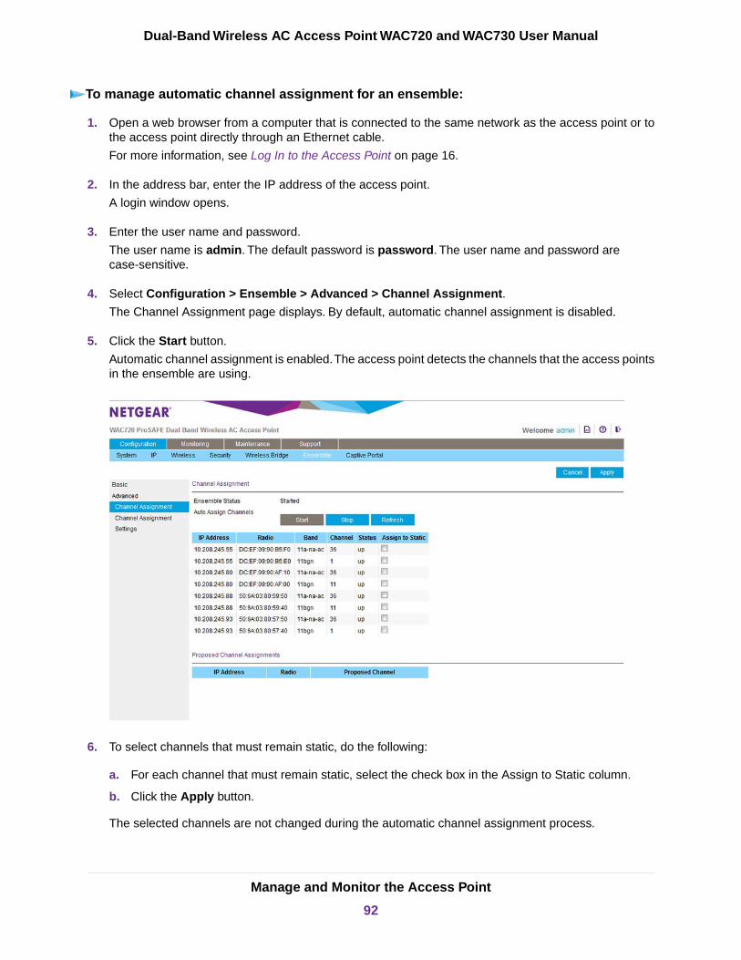
To manage automatic channel assignment for an ensemble:
1. Open a web browser from a computer that is connected to the same network as the access point or tothe access point directly through an Ethernet cable.
For more information, see Log In to the Access Point on page 16.
2. In the address bar, enter the IP address of the access point.
A login window opens.
3. Enter the user name and password.
The user name is admin. The default password is password. The user name and password arecase-sensitive.
4. Select Configuration > Ensemble > Advanced > Channel Assignment.
The Channel Assignment page displays. By default, automatic channel assignment is disabled.
5. Click the Start button.
Automatic channel assignment is enabled.The access point detects the channels that the access pointsin the ensemble are using.
6. To select channels that must remain static, do the following:
a. For each channel that must remain static, select the check box in the Assign to Static column.
b. Click the Apply button.
The selected channels are not changed during the automatic channel assignment process.
Manage and Monitor the Access Point
92
Dual-Band Wireless AC Access Point WAC720 and WAC730 User Manual
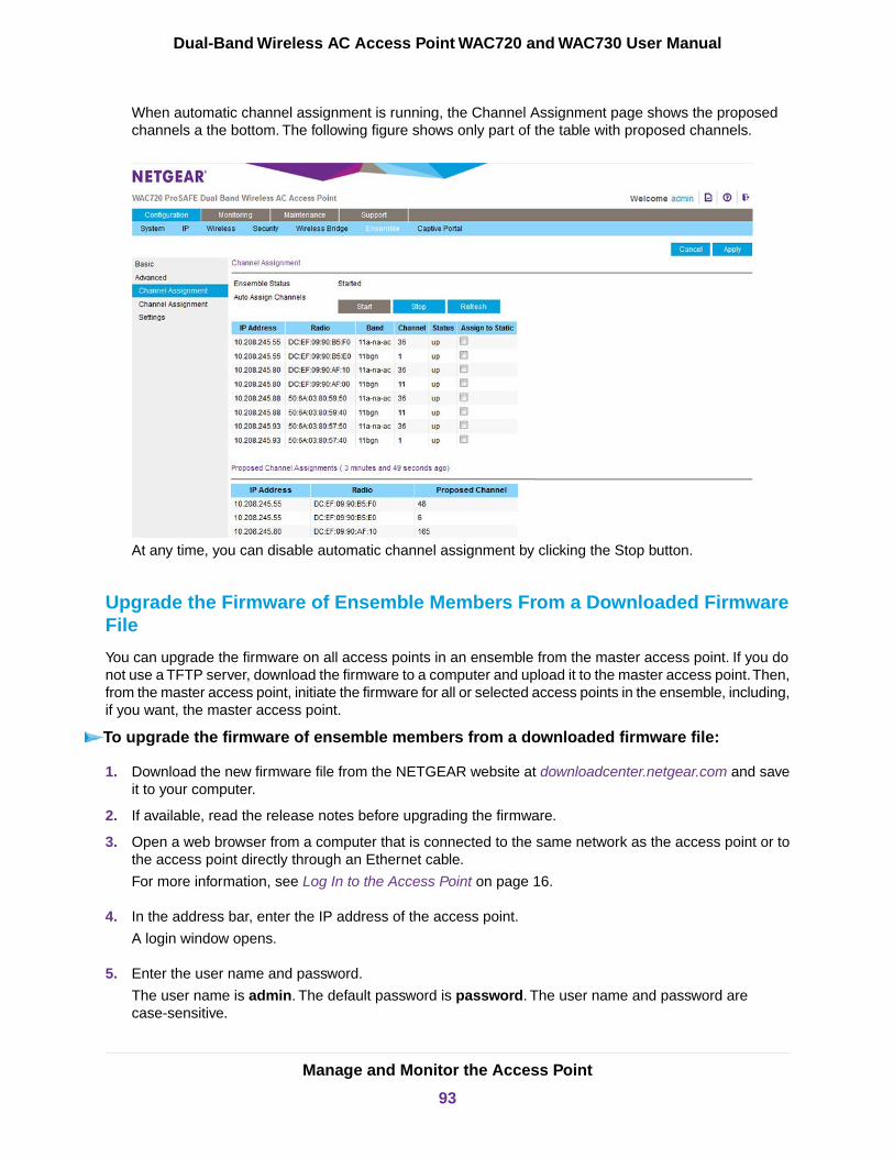
When automatic channel assignment is running, the Channel Assignment page shows the proposedchannels a the bottom. The following figure shows only part of the table with proposed channels.
At any time, you can disable automatic channel assignment by clicking the Stop button.
Upgrade the Firmware of Ensemble Members From a Downloaded FirmwareFile
You can upgrade the firmware on all access points in an ensemble from the master access point. If you donot use a TFTP server, download the firmware to a computer and upload it to the master access point.Then,from the master access point, initiate the firmware for all or selected access points in the ensemble, including,if you want, the master access point.
To upgrade the firmware of ensemble members from a downloaded firmware file:
1. Download the new firmware file from the NETGEAR website at downloadcenter.netgear.com and saveit to your computer.
2. If available, read the release notes before upgrading the firmware.
3. Open a web browser from a computer that is connected to the same network as the access point or tothe access point directly through an Ethernet cable.
For more information, see Log In to the Access Point on page 16.
4. In the address bar, enter the IP address of the access point.
A login window opens.
5. Enter the user name and password.
The user name is admin. The default password is password. The user name and password arecase-sensitive.
Manage and Monitor the Access Point
93
Dual-Band Wireless AC Access Point WAC720 and WAC730 User Manual

6. Select Maintenance > Ensemble Upgrade > Firmware Upgrade.
The Member Selection table shows the members of the ensemble, including the firmware versions ofthe members.
7. Click the Browse button.
A pop-up window opens.
8. Navigate to and select a firmware file to upload.
9. Click the Upgrade button.
An Alert pop-up window opens.
The firmware is uploaded to the master access point’s memory.
The firmware is uploaded to but not upgraded on the master access point. However,in Step 13 you can select the firmware to be upgraded on the master access point.
Note
10. In the Alert pop-up window, click the OK button.
The pop-up window closes. In the Upload Firmware section, a status bar shows the progress of theupload process. After the upload process is complete, the master access point restarts.
11. Log back in to the access point.
12. Select Maintenance > Ensemble Upgrade > Firmware Upgrade.
13. In the Member Selection table, select the check boxes for the members of the ensemble that you wantto upgrade, including, if you want, the master access point.
If you want to upgrade firmware on all members of the ensemble, select the check box in the tableheading.
14. Click the Apply button.
The firmware upgrade process starts.
The Firmware-transfer-status field in the table shows whether the firmware download to and validationin the member is successful.
Manage and Monitor the Access Point
94
Dual-Band Wireless AC Access Point WAC720 and WAC730 User Manual
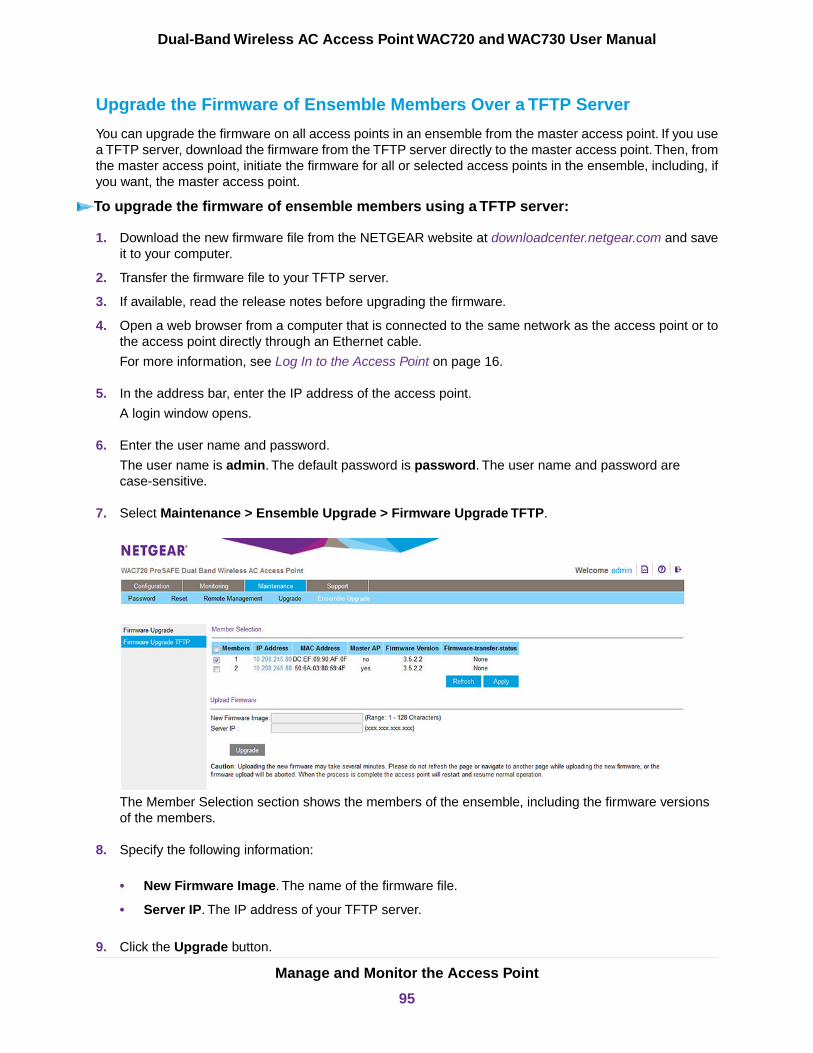
Upgrade the Firmware of Ensemble Members Over a TFTP Server
You can upgrade the firmware on all access points in an ensemble from the master access point. If you usea TFTP server, download the firmware from the TFTP server directly to the master access point.Then, fromthe master access point, initiate the firmware for all or selected access points in the ensemble, including, ifyou want, the master access point.
To upgrade the firmware of ensemble members using a TFTP server:
1. Download the new firmware file from the NETGEAR website at downloadcenter.netgear.com and saveit to your computer.
2. Transfer the firmware file to your TFTP server.
3. If available, read the release notes before upgrading the firmware.
4. Open a web browser from a computer that is connected to the same network as the access point or tothe access point directly through an Ethernet cable.
For more information, see Log In to the Access Point on page 16.
5. In the address bar, enter the IP address of the access point.
A login window opens.
6. Enter the user name and password.
The user name is admin. The default password is password. The user name and password arecase-sensitive.
7. Select Maintenance > Ensemble Upgrade > Firmware Upgrade TFTP.
The Member Selection section shows the members of the ensemble, including the firmware versionsof the members.
8. Specify the following information:
• New Firmware Image. The name of the firmware file.
• Server IP. The IP address of your TFTP server.
9. Click the Upgrade button.
Manage and Monitor the Access Point
95
Dual-Band Wireless AC Access Point WAC720 and WAC730 User Manual
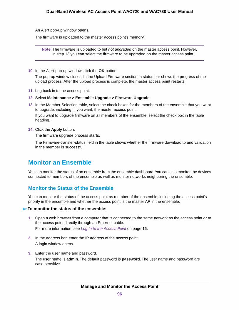
An Alert pop-up window opens.
The firmware is uploaded to the master access point’s memory.
The firmware is uploaded to but not upgraded on the master access point. However,in step 13 you can select the firmware to be upgraded on the master access point.
Note
10. In the Alert pop-up window, click the OK button.
The pop-up window closes. In the Upload Firmware section, a status bar shows the progress of theupload process. After the upload process is complete, the master access point restarts.
11. Log back in to the access point.
12. Select Maintenance > Ensemble Upgrade > Firmware Upgrade.
13. In the Member Selection table, select the check boxes for the members of the ensemble that you wantto upgrade, including, if you want, the master access point.
If you want to upgrade firmware on all members of the ensemble, select the check box in the tableheading.
14. Click the Apply button.
The firmware upgrade process starts.
The Firmware-transfer-status field in the table shows whether the firmware download to and validationin the member is successful.
Monitor an EnsembleYou can monitor the status of an ensemble from the ensemble dashboard.You can also monitor the devicesconnected to members of the ensemble as well as monitor networks neighboring the ensemble.
Monitor the Status of the Ensemble
You can monitor the status of the access point as member of the ensemble, including the access point’spriority in the ensemble and whether the access point is the master AP in the ensemble.
To monitor the status of the ensemble:
1. Open a web browser from a computer that is connected to the same network as the access point or tothe access point directly through an Ethernet cable.
For more information, see Log In to the Access Point on page 16.
2. In the address bar, enter the IP address of the access point.
A login window opens.
3. Enter the user name and password.
The user name is admin. The default password is password. The user name and password arecase-sensitive.
Manage and Monitor the Access Point
96
Dual-Band Wireless AC Access Point WAC720 and WAC730 User Manual
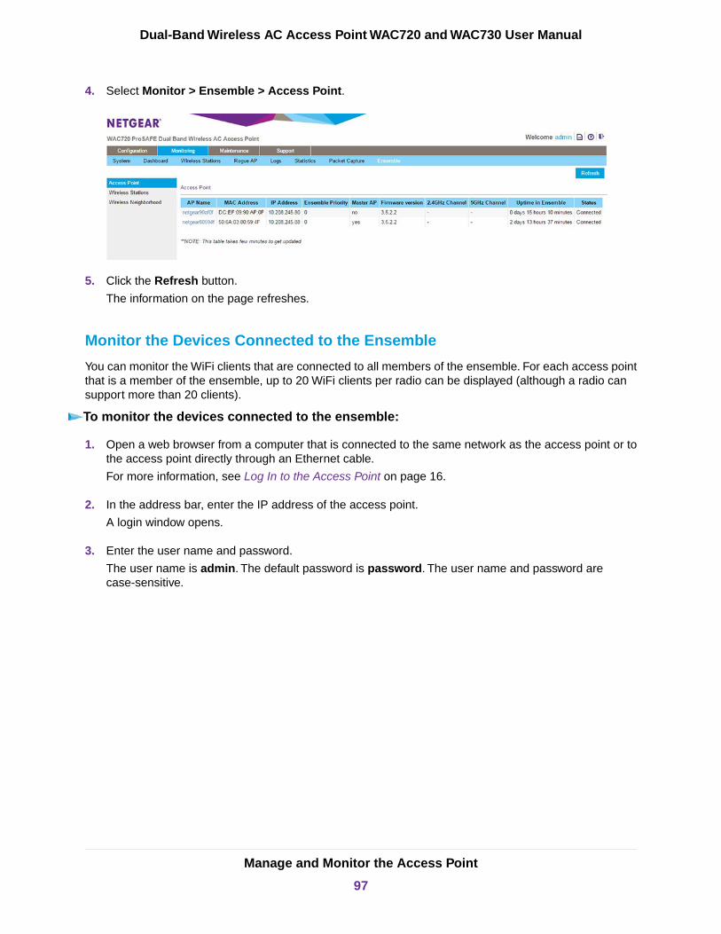
4. Select Monitor > Ensemble > Access Point.
5. Click the Refresh button.
The information on the page refreshes.
Monitor the Devices Connected to the Ensemble
You can monitor the WiFi clients that are connected to all members of the ensemble. For each access pointthat is a member of the ensemble, up to 20 WiFi clients per radio can be displayed (although a radio cansupport more than 20 clients).
To monitor the devices connected to the ensemble:
1. Open a web browser from a computer that is connected to the same network as the access point or tothe access point directly through an Ethernet cable.
For more information, see Log In to the Access Point on page 16.
2. In the address bar, enter the IP address of the access point.
A login window opens.
3. Enter the user name and password.
The user name is admin. The default password is password. The user name and password arecase-sensitive.
Manage and Monitor the Access Point
97
Dual-Band Wireless AC Access Point WAC720 and WAC730 User Manual
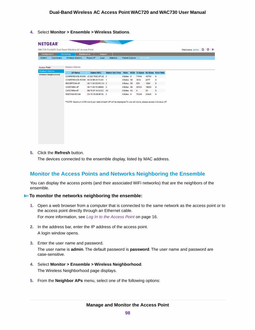
4. Select Monitor > Ensemble > Wireless Stations.
5. Click the Refresh button.
The devices connected to the ensemble display, listed by MAC address.
Monitor the Access Points and Networks Neighboring the Ensemble
You can display the access points (and their associated WiFi networks) that are the neighbors of theensemble.
To monitor the networks neighboring the ensemble:
1. Open a web browser from a computer that is connected to the same network as the access point or tothe access point directly through an Ethernet cable.
For more information, see Log In to the Access Point on page 16.
2. In the address bar, enter the IP address of the access point.
A login window opens.
3. Enter the user name and password.
The user name is admin. The default password is password. The user name and password arecase-sensitive.
4. Select Monitor > Ensemble > Wireless Neighborhood.
The Wireless Neighborhood page displays.
5. From the Neighbor APs menu, select one of the following options:
Manage and Monitor the Access Point
98
Dual-Band Wireless AC Access Point WAC720 and WAC730 User Manual

• Not in Ensemble. The access points that are not in the ensemble are displayed.
• In Ensemble. The access points that are in the ensemble are displayed.
• Both. Both the access points that are in the ensemble and that are not in the ensemble are displayed.(The following figure shows this option.)
Manage and Monitor the Access Point
99
Dual-Band Wireless AC Access Point WAC720 and WAC730 User Manual

5Configure Advanced Network and WiFiFeatures
This chapter describes how to configure the advanced features of the access point.
The chapter includes the following sections:
• Configure IPv6 Settings• Configure Spanning Tree Protocol, 802.1Q VLAN, and Link Layer Discovery Protocol• Configure Bonjour• Configure Advanced WiFi Settings• Configure Advanced Quality of Service Settings• Configure and Manage Quality of Service Policies• Configure Load Balancing• Manage Captive Portals• Configure WiFi Bridging
100
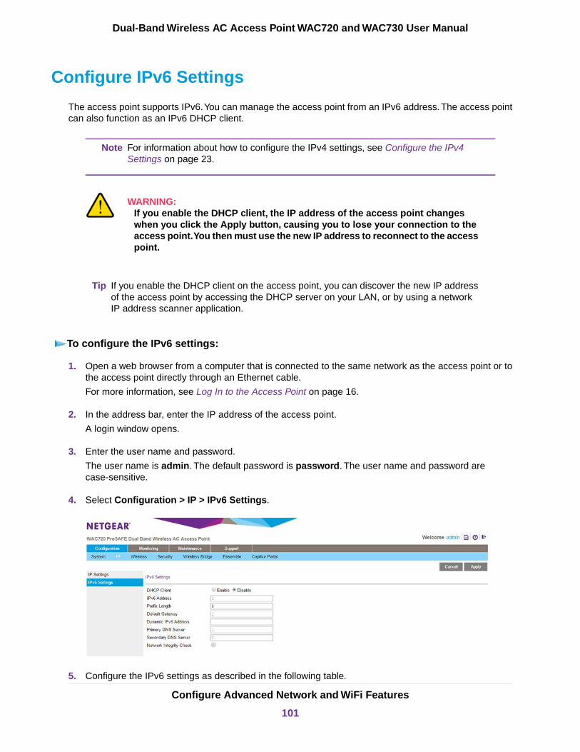
Configure IPv6 Settings
The access point supports IPv6.You can manage the access point from an IPv6 address. The access pointcan also function as an IPv6 DHCP client.
For information about how to configure the IPv4 settings, see Configure the IPv4Settings on page 23.
Note
WARNING:If you enable the DHCP client, the IP address of the access point changeswhen you click the Apply button, causing you to lose your connection to theaccess point.You then must use the new IP address to reconnect to the accesspoint.
If you enable the DHCP client on the access point, you can discover the new IP addressof the access point by accessing the DHCP server on your LAN, or by using a networkIP address scanner application.
Tip
To configure the IPv6 settings:
1. Open a web browser from a computer that is connected to the same network as the access point or tothe access point directly through an Ethernet cable.
For more information, see Log In to the Access Point on page 16.
2. In the address bar, enter the IP address of the access point.
A login window opens.
3. Enter the user name and password.
The user name is admin. The default password is password. The user name and password arecase-sensitive.
4. Select Configuration > IP > IPv6 Settings.
5. Configure the IPv6 settings as described in the following table.
Configure Advanced Network and WiFi Features
101
Dual-Band Wireless AC Access Point WAC720 and WAC730 User Manual
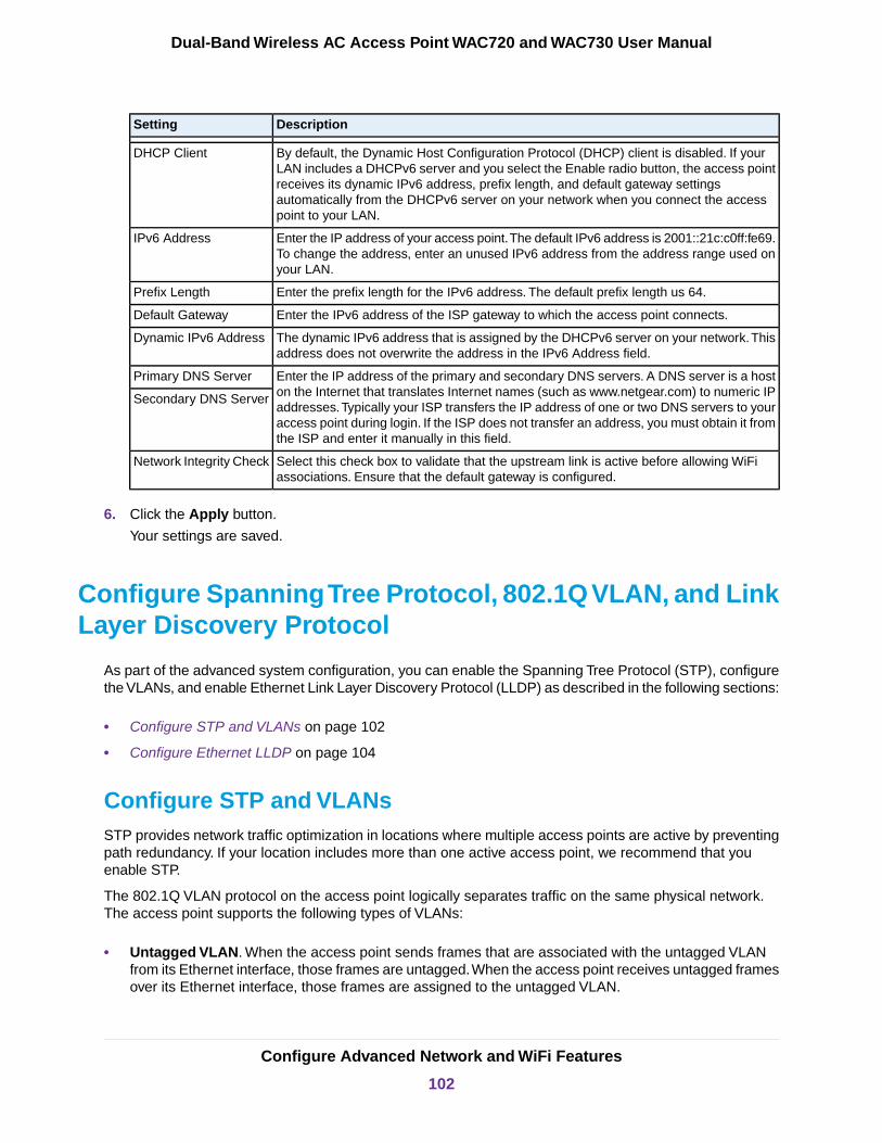
DescriptionSetting
By default, the Dynamic Host Configuration Protocol (DHCP) client is disabled. If yourLAN includes a DHCPv6 server and you select the Enable radio button, the access pointreceives its dynamic IPv6 address, prefix length, and default gateway settingsautomatically from the DHCPv6 server on your network when you connect the accesspoint to your LAN.
DHCP Client
Enter the IP address of your access point.The default IPv6 address is 2001::21c:c0ff:fe69.To change the address, enter an unused IPv6 address from the address range used onyour LAN.
IPv6 Address
Enter the prefix length for the IPv6 address. The default prefix length us 64.Prefix Length
Enter the IPv6 address of the ISP gateway to which the access point connects.Default Gateway
The dynamic IPv6 address that is assigned by the DHCPv6 server on your network.Thisaddress does not overwrite the address in the IPv6 Address field.
Dynamic IPv6 Address
Enter the IP address of the primary and secondary DNS servers. A DNS server is a hoston the Internet that translates Internet names (such as www.netgear.com) to numeric IPaddresses.Typically your ISP transfers the IP address of one or two DNS servers to youraccess point during login. If the ISP does not transfer an address, you must obtain it fromthe ISP and enter it manually in this field.
Primary DNS Server
Secondary DNS Server
Select this check box to validate that the upstream link is active before allowing WiFiassociations. Ensure that the default gateway is configured.
Network Integrity Check
6. Click the Apply button.
Your settings are saved.
Configure Spanning Tree Protocol, 802.1Q VLAN, and LinkLayer Discovery Protocol
As part of the advanced system configuration, you can enable the Spanning Tree Protocol (STP), configurethe VLANs, and enable Ethernet Link Layer Discovery Protocol (LLDP) as described in the following sections:
• Configure STP and VLANs on page 102
• Configure Ethernet LLDP on page 104
Configure STP and VLANsSTP provides network traffic optimization in locations where multiple access points are active by preventingpath redundancy. If your location includes more than one active access point, we recommend that youenable STP.
The 802.1Q VLAN protocol on the access point logically separates traffic on the same physical network.The access point supports the following types of VLANs:
• Untagged VLAN. When the access point sends frames that are associated with the untagged VLANfrom its Ethernet interface, those frames are untagged.When the access point receives untagged framesover its Ethernet interface, those frames are assigned to the untagged VLAN.
Configure Advanced Network and WiFi Features
102
Dual-Band Wireless AC Access Point WAC720 and WAC730 User Manual

Select the Untagged VLAN check box only if the hubs and switches on your LANsupport the 802.1Q VLAN protocol. Likewise, change the untagged VLAN value onlyif the hubs and switches on your LAN support the 802.1Q VLAN protocol.
Note
• Tagged VLAN. When you clear the Untagged VLAN check box, the access point tags all frames thatare sent from its Ethernet interface. Only incoming frames that are tagged with known VLAN IDs areaccepted.
• Management VLAN. The management VLAN can be active only when the access point functions asa point-to-point or point-to-multipoint bridge (see Configure WiFi Bridging on page 132).The managementVLAN is used for managing traffic (Telnet, SNMP, and HTTP) to and from the access point.
Frames belonging to the management VLAN are not given any 802.1Q header when they are sent over thetrunk. If a port is in a single VLAN, it can be untagged. However, if the port is a member of multiple VLANs,it must be tagged.
To configure STP and VLANs:
1. Open a web browser from a computer that is connected to the same network as the access point or tothe access point directly through an Ethernet cable.
For more information, see Log In to the Access Point on page 16.
2. In the address bar, enter the IP address of the access point.
A login window opens.
3. Enter the user name and password.
The user name is admin. The default password is password. The user name and password arecase-sensitive.
4. Select Configuring > System > Advanced > General.
5. Specify the settings as described in the following table.
DescriptionSetting
Spanning Tree Protocol
Select the Enable radio button to enable STP to prevent path redundancy. By default,the Disable radio button is selected.
Spanning Tree Protocol
Configure Advanced Network and WiFi Features
103
Dual-Band Wireless AC Access Point WAC720 and WAC730 User Manual
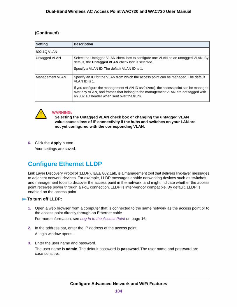
(Continued)
DescriptionSetting
802.1Q VLAN
Select the Untagged VLAN check box to configure one VLAN as an untagged VLAN. Bydefault, the Untagged VLAN check box is selected.
Specify a VLAN ID. The default VLAN ID is 1.
Untagged VLAN
Specify an ID for the VLAN from which the access point can be managed. The defaultVLAN ID is 1.
If you configure the management VLAN ID as 0 (zero), the access point can be managedover any VLAN, and frames that belong to the management VLAN are not tagged withan 802.1Q header when sent over the trunk.
Management VLAN
WARNING:Selecting the Untagged VLAN check box or changing the untagged VLANvalue causes loss of IP connectivity if the hubs and switches on your LAN arenot yet configured with the corresponding VLAN.
6. Click the Apply button.
Your settings are saved.
Configure Ethernet LLDPLink Layer Discovery Protocol (LLDP), IEEE 802.1ab, is a management tool that delivers link-layer messagesto adjacent network devices. For example, LLDP messages enable networking devices such as switchesand management tools to discover the access point in the network, and might indicate whether the accesspoint receives power through a PoE connection. LLDP is inter-vendor compatible. By default, LLDP isenabled on the access point.
To turn off LLDP:
1. Open a web browser from a computer that is connected to the same network as the access point or tothe access point directly through an Ethernet cable.
For more information, see Log In to the Access Point on page 16.
2. In the address bar, enter the IP address of the access point.
A login window opens.
3. Enter the user name and password.
The user name is admin. The default password is password. The user name and password arecase-sensitive.
Configure Advanced Network and WiFi Features
104
Dual-Band Wireless AC Access Point WAC720 and WAC730 User Manual
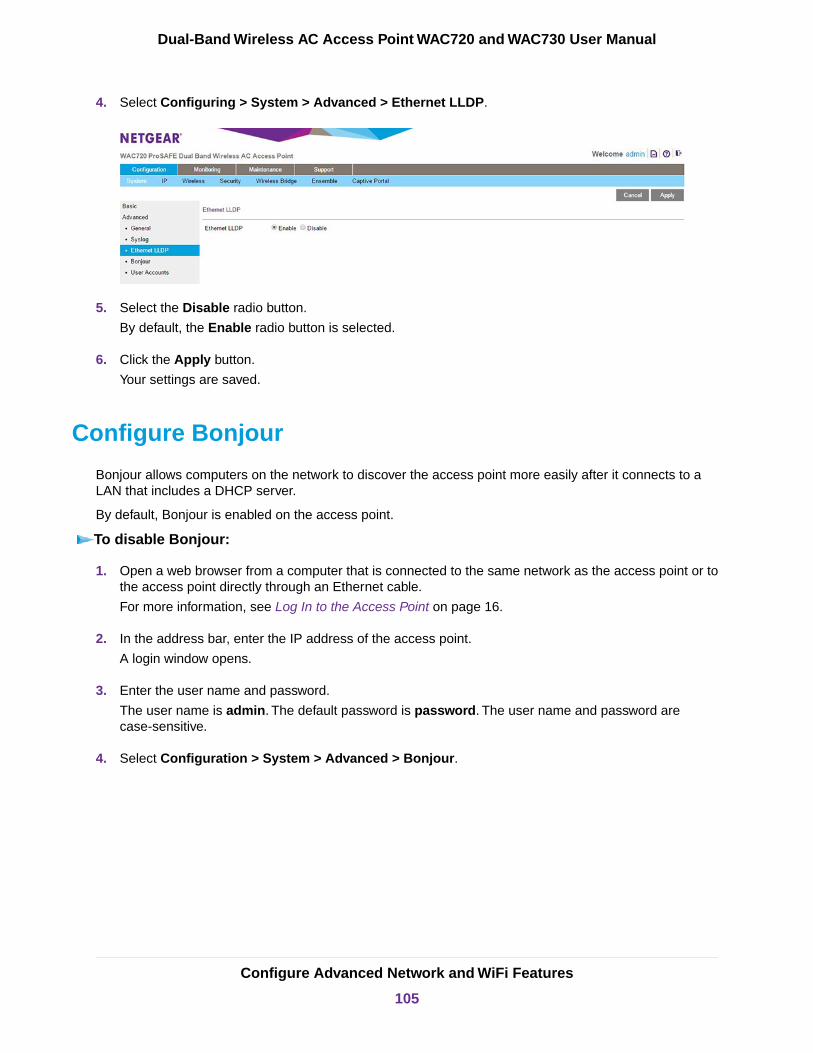
4. Select Configuring > System > Advanced > Ethernet LLDP.
5. Select the Disable radio button.
By default, the Enable radio button is selected.
6. Click the Apply button.
Your settings are saved.
Configure Bonjour
Bonjour allows computers on the network to discover the access point more easily after it connects to aLAN that includes a DHCP server.
By default, Bonjour is enabled on the access point.
To disable Bonjour:
1. Open a web browser from a computer that is connected to the same network as the access point or tothe access point directly through an Ethernet cable.
For more information, see Log In to the Access Point on page 16.
2. In the address bar, enter the IP address of the access point.
A login window opens.
3. Enter the user name and password.
The user name is admin. The default password is password. The user name and password arecase-sensitive.
4. Select Configuration > System > Advanced > Bonjour.
Configure Advanced Network and WiFi Features
105
Dual-Band Wireless AC Access Point WAC720 and WAC730 User Manual
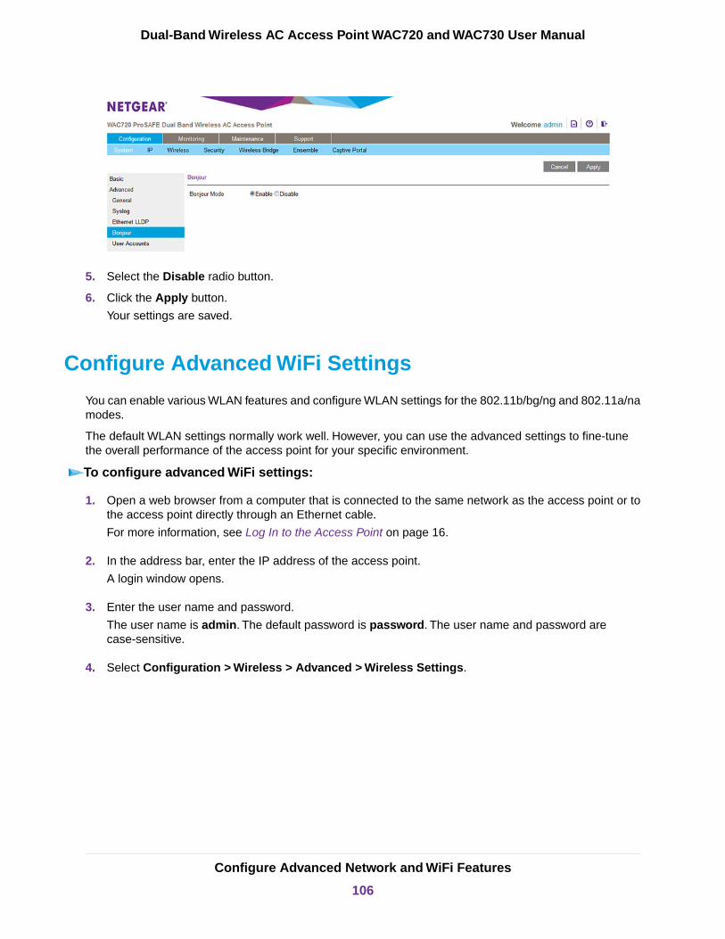
5. Select the Disable radio button.
6. Click the Apply button.
Your settings are saved.
Configure Advanced WiFi Settings
You can enable various WLAN features and configure WLAN settings for the 802.11b/bg/ng and 802.11a/namodes.
The default WLAN settings normally work well. However, you can use the advanced settings to fine-tunethe overall performance of the access point for your specific environment.
To configure advanced WiFi settings:
1. Open a web browser from a computer that is connected to the same network as the access point or tothe access point directly through an Ethernet cable.
For more information, see Log In to the Access Point on page 16.
2. In the address bar, enter the IP address of the access point.
A login window opens.
3. Enter the user name and password.
The user name is admin. The default password is password. The user name and password arecase-sensitive.
4. Select Configuration > Wireless > Advanced > Wireless Settings.
Configure Advanced Network and WiFi Features
106
Dual-Band Wireless AC Access Point WAC720 and WAC730 User Manual

The previous figure shows part of the page.
5. Select an Antenna radio button to specify whether the settings apply to the default internal antenna orto one or more optional external antennas:
• Internal. Enables the internal antenna. This is the default setting.
• External. Enables an optional external antenna or antennas.
6. If you want to disable the calibration training frame (CTF) for the antenna, clear the CTF radio button.
By default, the CTF radio button is selected and we recommend that you keep the CTF enabled. Disablingthe CTF reduces the throughput and performance of the access point and causes connected users toexperience slow Internet access.
7. Specify the settings as described in the following table.
Configure Advanced Network and WiFi Features
107
Dual-Band Wireless AC Access Point WAC720 and WAC730 User Manual

DescriptionSetting
Enter the Request to Send (RTS) threshold. The default setting is 2347.
If the packet size is equal to or less than the RTS threshold, the access point usesthe Carrier Sense Multiple Access with Collision Detection (CSMA/CD) mechanism,and the data frame is transmitted immediately after the silence period.
If the packet size is larger than the RTS threshold, the access point uses the CSMAwith Collision Avoidance (CSMA/CA) mechanism. In this situation, the transmittingstation sends an RTS packet to the receiving station and waits for the receiving stationto return a Clear to Send (CTS) packet before sending the actual packet data.
RTS Threshold (0–2347)
Enter the maximum packet size that is used for the fragmentation of data packets.Packets that are larger than the specified fragmentation length are broken up intosmaller packets before being transmitted.The fragmentation length must be an evennumber. The default setting is 2346.
Fragmentation Length(256–2346)
Enter the interval between 100 ms and 1000 ms for each beacon transmission, whichallows the access point to synchronize the WiFi network. The default setting is 100.
Beacon Interval (100–1000)
Select the Enable radio button to allow the aggregation of several MAC frames intoa single large frame to achieve higher throughput. Enabling the aggregated MACprotocol data unit (A-MPDU) could lead to better network performance. By default,the Enable radio button is selected.
AMPDU
Select the Enable radio button to allow transmission of successive frames at differenttransmit powers. Enabling reduced interframe space (RIFS) could lead to betternetwork performance. By default, the Disable radio button is selected.
RIFS Transmission
Enter the delivery traffic indication message (DTIM) interval, also referred to as thedata beacon rate, which indicates the beacon delivery traffic indication messageperiod in multiples of beacon intervals. This value must be between 1 and 255. Thedefault setting is 3.
DTIM Interval (1–255)
Select this check box to enable support for additional regulatory domains that arenot in the current standard; support includes the addition of a country informationelement to beacons, probe requests, and probe responses.This check box is selectedby default.
802.11d
This setting does not applyto the 802.11a/a-na-acmodes.
Enter the maximum number of WiFi clients that can simultaneously connect to theaccess point at one time. The default setting is 200 clients.
Max. Wireless Clients
Select the Enable radio button to allow frame burst. Frame burst can boost thedownstream throughput. By default, the Disable radio button is selected.
Frame Burst
Select the multicast traffic transmission rate you want the AP to support. The defaultvalue is Auto. For the 2.4 GHz radio, the Auto value is 1 Mbps. For the 5 GHz radio,the Auto value is 6 Mbps.
Fixed Multicast Rate
Enabling multicast and broadcast rate limiting can improve overall networkperformance by limiting the number of packets transmitted across the network.
By default the Multicast/Broadcast Rate Limiting check box is selected and youcan configure the rate limit and rate limit burst.
Broadcast/Multicast Rate
For multicast and broadcast rate limiting, the default and maximum rate limit settingis 50 packets per second. The supported range is from 1 to 50 pps.
Rate Limit
Configure Advanced Network and WiFi Features
108
Dual-Band Wireless AC Access Point WAC720 and WAC730 User Manual
(Continued)
DescriptionSetting
For multicast and broadcast rate limiting, The default and maximum rate limit burstsetting is 75 packets per second. The supported range is from 1 to 75 pps.
Rate Limit Burst
Select the 802.11n 256 QAM check box to enable the 2.4 GHz radio to function over256-quadrature amplitude modulation (QAM). By default, 256-QAM is enabled forthe 5 GHz radio but the 2.4 GHz radio is not enabled to function over 256-QAM, thatis, the check box is cleared.
802.11n 256 QAM
This setting does not applyto the 802.11a/a-na-acmodes.
8. Click the Apply button.
Your settings are saved.
Configure Advanced Quality of Service Settings
For most networks, the default Quality of Service (QoS) queue settings work well. For information abouthow to configure basic QoS, see Configure Basic WiFi Quality of Service on page 59.
You can specify the settings on multiple queues for increased throughput and better performance ofdifferentiated WiFi traffic such as Voice over IP (VoIP), other types of audio, video, and streaming media,as well as traditional IP data.
The advanced QoS options on the access point are as follows:
• AP EDCA parameters. Specify the access point (AP) Enhanced Distributed Channel Access (EDCA)settings for different types of data transmitted from the access point to WiFi clients.
• Station EDCA parameters. Specify the station EDCA parameters for different types of data transmittedfrom the WiFi clients to the access point. If WMM is disabled, you cannot configure the Station EDCAparameters. (For information about how to enable WMM, see Configure Basic WiFi Quality of Serviceon page 59.)
When you configure the EDCA settings, the access point can leverage existing information in the IP packetheader that is related to the Type of Service (ToS). The access point examines the ToS field in the headersof all packets that it processes. Based on the value in a packet’s ToS field, the access point prioritizes thepacket for transmission by assigning it to one of the queues. A different type of data is associated with eachqueue.You can configure how the access point treats each queue.
The queues defined for different types of data transmitted from AP-to-station and station-to-AP are as follows:
• Data 0 (Best Effort). Medium priority queue, medium throughput and delay. Most traditional IP data issent to this queue.
• Data 1 (Background). Lowest priority queue, high throughput. Bulk data that requires maximumthroughput and is not time-sensitive is sent to this queue (FTP data, for example).
• Data 2 (Video). Highest priority queue, minimum delay. Time-sensitive video data is automatically sentto this queue.
• Data 3 (Voice). Highest priority queue, minimum delay.Time-sensitive data such as VoIP and streamingmedia are automatically sent to this queue.
Configure Advanced Network and WiFi Features
109
Dual-Band Wireless AC Access Point WAC720 and WAC730 User Manual
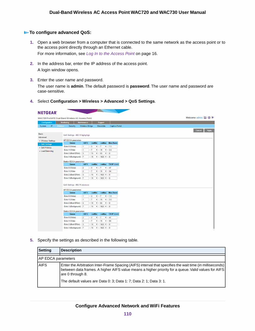
To configure advanced QoS:
1. Open a web browser from a computer that is connected to the same network as the access point or tothe access point directly through an Ethernet cable.
For more information, see Log In to the Access Point on page 16.
2. In the address bar, enter the IP address of the access point.
A login window opens.
3. Enter the user name and password.
The user name is admin. The default password is password. The user name and password arecase-sensitive.
4. Select Configuration > Wireless > Advanced > QoS Settings.
5. Specify the settings as described in the following table.
DescriptionSetting
AP EDCA parameters
Enter the Arbitration Inter-Frame Spacing (AIFS) interval that specifies the wait time (in milliseconds)between data frames. A higher AIFS value means a higher priority for a queue.Valid values for AIFSare 0 through 8.
The default values are Data 0: 3; Data 1: 7; Data 2: 1; Data 3: 1.
AIFS
Configure Advanced Network and WiFi Features
110
Dual-Band Wireless AC Access Point WAC720 and WAC730 User Manual

(Continued)
DescriptionSetting
Enter the minimum contention window (cwMin) value that specifies the upper limit (in milliseconds)of a range from which the initial random back-off wait time is determined. Decreasing this valueincreases the priority of the queue. The value for cwMin must be lower than the value for cwMax.Valid values are 0, 1, 3, 7, 15, 31, 63, 127, 255, 511, and 1023.
The default values are Data 0: 15; Data 1: 15; Data 2: 7; Data 3: 3.
cwMin
Enter the maximum contention window (cwMax) value that specifies the upper limit (in milliseconds)for the doubling of the random back-off value. Decreasing this value increases the priority of thequeue. The value for cwMax must be higher than the value for cwMin. Valid values are 0, 1, 3, 7,15, 31, 63, 127, 255, 511, and 1023.
The default values are Data 0: 63; Data 1: 1023; Data 2: 15; Data 3: 7.
cwMax
Enter the maximum burst value that specifies the maximum burst length (in microseconds) allowedfor packet bursts on the WiFi network. A packet burst is a collection of multiple frames transmittedwithout header information. Decreasing this value increases the priority of the queue. Valid valuesfor maximum burst length are all multiples of 32 between 0 and 8192, inclusive of 0 and 8192.
The default values are Data 0: 0; Data 1: 0; Data 2: 3008; Data 3: 1504.
Max. Burst
Station EDCA parameters
Enter the Arbitration Inter-Frame Spacing (AIFS) interval that specifies the wait time (in milliseconds)between data frames. A higher AIFS value means a higher priority for a queue.Valid values for AIFSare 0 through 8.
The default values are Data 0: 3; Data 1: 7; Data 2: 2; Data 3: 2.
AIFS
Enter the minimum contention window (cwMin) value that specifies the upper limit (in milliseconds)of a range from which the initial random back-off wait time is determined. Decreasing this valueincreases the priority of the queue. The value for cwMin must be lower than the value for cwMax.Valid values are 0, 1, 3, 7, 15, 31, 63, 127, 255, 511, and 1023.
The default values are Data 0: 15; Data 1: 15; Data 2: 7; Data 3: 3.
cwMin
Enter the maximum contention window (cwMax) value that specifies the upper limit (in milliseconds)for the doubling of the random back-off value. Decreasing this value increases the priority of thequeue. The value for cwMax must be higher than the value for cwMin. Valid values are 0, 1, 3, 7,15, 31, 63, 127, 255, 511, and 1023.
The default values are Data 0: 1023; Data 1: 1023; Data 2: 15; Data 3: 7.
cwMax
Enter the transmission opportunity (TXOP) value that specifies the time interval (in microseconds)in which a client station can initiate transmissions on the WiFi medium (WM). Decreasing this valueincreases the priority of the queue. Valid values for TXOP Limit are all multiples of 32 between 0and 8192, inclusive of 0 and 8192.
The default values are Data 0: 0; Data 1: 0; Data 2: 3008; Data 3: 1504.
TXOP Limit
6. Click the Apply button.
Your settings are saved.
Configure Advanced Network and WiFi Features
111
Dual-Band Wireless AC Access Point WAC720 and WAC730 User Manual

Configure and Manage Quality of Service Policies
The access point lets you configure and apply QoS policies to WiFi clients. In each QoS policy, you canspecify multiple classifications (match clauses) and apply traffic to eight priority queues based on the followinginformation in the Layer 2, Layer 3, Layer 3 IP headers, and Layer 4:
• IP precedence. Indicates the IP Type of Service (ToS) or precedence in the IP headers.
• IP DSCP. Indicates the Differentiated Services Code Point (DSCP) marking in the IP header.
• IP protocol 119. Indicates the IP protocol field in the IP header with value 119.
• 802.1P. Indicates the 3-bit Class of Service (CoS) field in the class header.
• IP protocol. Indicates the protocol field in the IP header.
• EtherType. Indicates the EtherType field in Ethernet-II frame header.
• Source MAC. Indicates the source MAC address in Ethernet-II frame header.
• Destination MAC. Indicates the destination MAC address in Ethernet-II frame header.
• Source IP. Indicates the source IP address in the IP header.
• Destination IP. Indicates the destination IP address in the IP header.
• Source port. Indicates the source port number in the port header.
• Destination port. Indicates the destination port number in the port header.
For each classification in a QoS policy, you can configure rate limiting by specifying the maximum bit rateand maximum burst rate. Packets that exceed the maximum bit rate are retained in the traffic queue andare processed when transmission falls again below the maximum bit rate.You can also configure the overallmaximum bit rate and maximum burst rate for the entire WiFi interface.
Configure a New QoS PolicyYou can configure up to eight QoS policies.
To configure a new QoS policy:
1. Open a web browser from a computer that is connected to the same network as the access point or tothe access point directly through an Ethernet cable.
For more information, see Log In to the Access Point on page 16.
2. In the address bar, enter the IP address of the access point.
A login window opens.
3. Enter the user name and password.
The user name is admin. The default password is password. The user name and password arecase-sensitive.
Configure Advanced Network and WiFi Features
112
Dual-Band Wireless AC Access Point WAC720 and WAC730 User Manual

4. Select Configuration > Wireless > Advanced > QoS Policies.
You can configure QoS policies for 802.11 bg/ng/bgn devices, 802.11 a/a-na-ac devices, or both typesof devices.
5. From the Create Policy menu, select NEW.
If you did not yet set up any QoS policies, NEW is the only selection possible.
6. In the Policy Name field, enter a name for the new QoS policy.
7. Specify a classification for the QoS policy as described in the following table.
Depending on your selection from the Match Frame Fields menu, MatchClassifications appears either as a menu from which you must make a selection oras a field in which you must enter information.
Note
Configure Advanced Network and WiFi Features
113
Dual-Band Wireless AC Access Point WAC720 and WAC730 User Manual

DescriptionSetting
From the Match Classifications menu, select the DSCP traffic classagainst which the information in the IP header must be matched:
• Routine(0)
• Priority(1)
• Immediate(2)
• Flash(3)
• Flash Override(4)
• Critic/CCP(5)
• Inter Control(6)
• Network Control(7)
IP PrecedenceMatch Frame Fieldsand MatchClassifications
From the Match Classifications menu, select the DSCP marking againstwhich the information in the IP header must be matched:
• Best Effort
• Assured Forwarding - Class 1 Low
• Assured Forwarding - Class 1 Medium
• Assured Forwarding - Class 1 High
• Assured Forwarding - Class 2 Low
• Assured Forwarding - Class 2 Medium
• Assured Forwarding - Class 2 High
• Assured Forwarding - Class 3 Low
• Assured Forwarding - Class 3 Medium
• Assured Forwarding - Class 3 High
• Assured Forwarding - Class 4 Low
• Assured Forwarding - Class 4 Medium
• Assured Forwarding - Class 4 High
• Class Selector 1
• Class Selector 2
• Class Selector 3
• Class Selector 4
• Class Selector 5
• Class Selector 6
• Class Selector 7
• Expedited Forwarding
IP DCSPMatch Frame Fieldsand MatchClassifications(continued)
Configure Advanced Network and WiFi Features
114
Dual-Band Wireless AC Access Point WAC720 and WAC730 User Manual
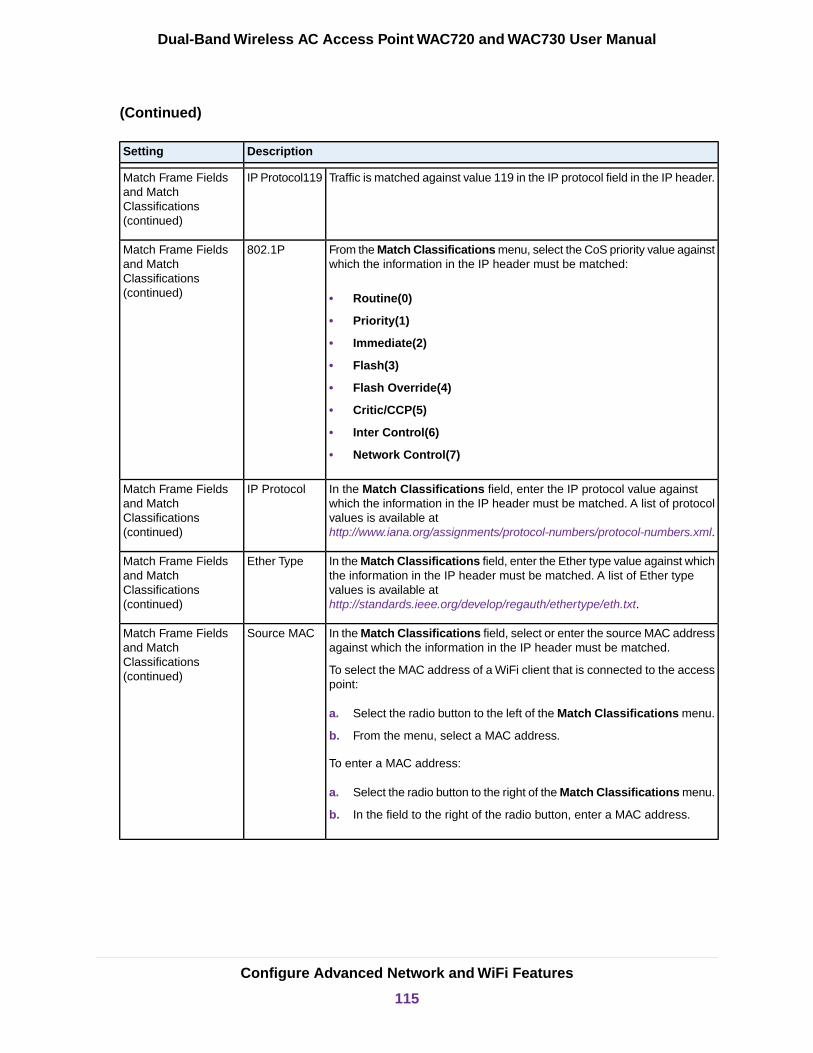
(Continued)
DescriptionSetting
Traffic is matched against value 119 in the IP protocol field in the IP header.IP Protocol119Match Frame Fieldsand MatchClassifications(continued)
From the Match Classifications menu, select the CoS priority value againstwhich the information in the IP header must be matched:
• Routine(0)
• Priority(1)
• Immediate(2)
• Flash(3)
• Flash Override(4)
• Critic/CCP(5)
• Inter Control(6)
• Network Control(7)
802.1PMatch Frame Fieldsand MatchClassifications(continued)
In the Match Classifications field, enter the IP protocol value againstwhich the information in the IP header must be matched. A list of protocolvalues is available athttp://www.iana.org/assignments/protocol-numbers/protocol-numbers.xml.
IP ProtocolMatch Frame Fieldsand MatchClassifications(continued)
In the Match Classifications field, enter the Ether type value against whichthe information in the IP header must be matched. A list of Ether typevalues is available athttp://standards.ieee.org/develop/regauth/ethertype/eth.txt.
Ether TypeMatch Frame Fieldsand MatchClassifications(continued)
In the Match Classifications field, select or enter the source MAC addressagainst which the information in the IP header must be matched.
To select the MAC address of a WiFi client that is connected to the accesspoint:
a. Select the radio button to the left of the Match Classifications menu.
b. From the menu, select a MAC address.
To enter a MAC address:
a. Select the radio button to the right of the Match Classifications menu.
b. In the field to the right of the radio button, enter a MAC address.
Source MACMatch Frame Fieldsand MatchClassifications(continued)
Configure Advanced Network and WiFi Features
115
Dual-Band Wireless AC Access Point WAC720 and WAC730 User Manual
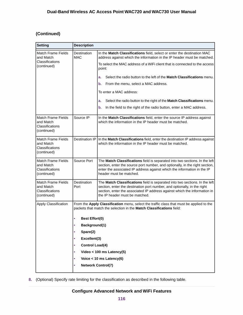
(Continued)
DescriptionSetting
In the Match Classifications field, select or enter the destination MACaddress against which the information in the IP header must be matched.
To select the MAC address of a WiFi client that is connected to the accesspoint:
a. Select the radio button to the left of the Match Classifications menu.
b. From the menu, select a MAC address.
To enter a MAC address:
a. Select the radio button to the right of the Match Classifications menu.
b. In the field to the right of the radio button, enter a MAC address.
DestinationMAC
Match Frame Fieldsand MatchClassifications(continued)
In the Match Classifications field, enter the source IP address againstwhich the information in the IP header must be matched.
Source IPMatch Frame Fieldsand MatchClassifications(continued)
In the Match Classifications field, enter the destination IP address againstwhich the information in the IP header must be matched.
Destination IPMatch Frame Fieldsand MatchClassifications(continued)
The Match Classifications field is separated into two sections. In the leftsection, enter the source port number, and optionally, in the right section,enter the associated IP address against which the information in the IPheader must be matched.
Source PortMatch Frame Fieldsand MatchClassifications(continued)
The Match Classifications field is separated into two sections. In the leftsection, enter the destination port number, and optionally, in the rightsection, enter the associated IP address against which the information inthe IP header must be matched.
DestinationPort
Match Frame Fieldsand MatchClassifications(continued)
From the Apply Classification menu, select the traffic class that must be applied to thepackets that match the selection in the Match Classifications field:
• Best Effort(0)
• Background(1)
• Spare(2)
• Excellent(3)
• Control Load(4)
• Video < 100 ms Latency(5)
• Voice < 10 ms Latency(6)
• Network Control(7)
Apply Classification
8. (Optional) Specify rate limiting for the classification as described in the following table.
Configure Advanced Network and WiFi Features
116
Dual-Band Wireless AC Access Point WAC720 and WAC730 User Manual

DescriptionSetting
Enter a value between 1 and 1,000,000 Kbytes/sec to specify the maximum data rateup to which packets that match the classification are queued for transmission andsent immediately over the WiFi interface.This value applies only to traffic that matchesthe classification.
When the maximum rate is exceeded, packets are retained in thequeue and sent when the transmission falls again below themaximum rate.
Note
Basic RateClassificationRate Limiting
Enter a value between 1 and 204,800,000 bytes to specify the maximum amount ofdata that can be transmitted in a burst for packets that match the classification. Thisvalue applies only to traffic that matches the classification.
Burst Rate
9. Click the Add button.
The classification is added to the Classifications field.
10. To add another classification to the QoS policy, repeat Step 7, Step 8, and Step 9.
11. Click the Apply button.
The QoS policy is saved.
Rate limiting for the WiFi interface is an optional setting that applies to all traffic onthe WiFi interface. Unlike classification rate limiting, which you can specify for eachclassification, rate limiting for the WiFi interface you must specify only once.
Note
Modify a QoS PolicyTo modify a QoS policy:
1. Open a web browser from a computer that is connected to the same network as the access point or tothe access point directly through an Ethernet cable.
For more information, see Log In to the Access Point on page 16.
2. In the address bar, enter the IP address of the access point.
A login window opens.
3. Enter the user name and password.
The user name is admin. The default password is password. The user name and password arecase-sensitive.
4. Select Configuration > Wireless > Advanced > QoS Policies.
The QoS Policies page displays.
5. From the Create Policy menu, select the policy that you want to modify.
6. To modify a classification, you must delete the classification and add a new classification:
Configure Advanced Network and WiFi Features
117
Dual-Band Wireless AC Access Point WAC720 and WAC730 User Manual

a. In the Classification field, select the old classification.
b. Click the Delete Classification button.
c. Add a new classification.
For information about how to add a classification, see Step 7 through Step 9 in the procedure to configurea new QoS policy.
7. To change the name of the policy, in the Policy Name field, enter a new name for the QoS policy.
8. Click the Apply button.
Your settings are saved.
Delete a QoS PolicyTo delete a QoS policy:
1. Open a web browser from a computer that is connected to the same network as the access point or tothe access point directly through an Ethernet cable.
For more information, see Log In to the Access Point on page 16.
2. In the address bar, enter the IP address of the access point.
A login window opens.
3. Enter the user name and password.
The user name is admin. The default password is password. The user name and password arecase-sensitive.
4. Select Configuration > Wireless > Advanced > QoS Policies.
The QoS Policies page displays.
5. From the Create Policy menu, select the policy that you want to delete.
6. Click the Delete Policy button.
7. Click the Apply button.
Your settings are saved.
Configure Load Balancing
You can set network utilization thresholds on the access point to maintain the speed and performance ofthe WiFi network as clients associate with and disassociate from the access point. The load balancingsettings apply to both radios.
As an option, you can specify the percentage of network bandwidth utilization that is allowed on a radiobefore the access point stops accepting new client associations. Whether client associations are alloweddepends on the specified percentage and the WLAN utilization of the radio:
Configure Advanced Network and WiFi Features
118
Dual-Band Wireless AC Access Point WAC720 and WAC730 User Manual

• New client associations are allowed if the radio’s WLAN utilization is lower than the specified percentageof network bandwidth utilization.
• New client associations are prevented if the radio’s WLAN utilization is higher than the specifiedpercentage of network bandwidth utilization.
For more information about the WLAN utilization, see View the Standalone Dashboard on page 80.
To enable and configure load balancing:
1. Open a web browser from a computer that is connected to the same network as the access point or tothe access point directly through an Ethernet cable.
For more information, see Log In to the Access Point on page 16.
2. In the address bar, enter the IP address of the access point.
A login window opens.
3. Enter the user name and password.
The user name is admin. The default password is password. The user name and password arecase-sensitive.
4. Select Configuration > Wireless > Advanced > Load Balancing.
5. To enable load balancing, select the Enabled radio button.
By default, the Disabled radio button is selected and load balancing is disabled.
6. In the Utilization For No New Associations (%) field, enter the percentage of network bandwidthutilization that is allowed on the radios before the access point stops accepting new client associations.
The default is 0, which means that all new associations are allowed, regardless of the utilization rate.
7. Click the Apply button.
Your settings are saved.
Configure Advanced Network and WiFi Features
119
Dual-Band Wireless AC Access Point WAC720 and WAC730 User Manual
Manage Captive Portals
A captive portal requires users to log in through a special login page (splash page, also referred to as weblocale) so that guests or users with a valid user name and password can access the Internet through theaccess point.
The access point supports two captive portal instances (NETGEAR and NETGEAR-1).You can create upto six splash pages (three per captive portal profile). However, for each captive portal instance, only onesplash page can be active at any time.
The following sections describe chronologically the procedures that are involved in setting up a captiveportal:
1. If you want to use the Facebook Wi-Fi capability as an authentication mode, do the following:
a. Enable the Access Point to Register With Facebook on page 121
b. Set Up Facebook Wi-Fi for a Captive Portal Profile on page 124
2. Specify Captive Portal Profile Settings and Enable the Captive Portal Instance on page 121
For each captive portal instance that you want to be available, you must specify the protocol, whetherusers are redirected to a specific website, the time-outs, and the authentication mode.
3. Add User Accounts to the Local Database for Captive Portal Access on page 126
If a captive portal instance uses the local database for user authentication, you must add a user accountto the local database for each user that you want to grant access through the captive portal.You do notneed to add users accounts to the local user database if the authentication for a captive portal instanceis configured for guest access or uses a RADIUS server.
4. (Optional) Upload a Custom Logo on page 128
Follow this procedure only if you want to be able to select a custom logo when you configure a customsplash page.
5. Configure a Default or Custom Captive Portal Splash Page on page 129
You can use the default splash page that the access point provides or set up a custom splash page.
6. Enable the Global Captive Portal Mode on page 131
You only need to enable the captive portal mode once on the access point. After the mode is enabled,it applies to both captive portal instances.
7. Select one of the captive portal instances for a WiFi security profile (see Configure and Enable WiFiSecurity Profiles on page 39).
After you select the captive portal instance for a WiFi security profile, the WiFi network that is associatedwith the WiFi security profile becomes accessible only through the captive portal.
Configure Advanced Network and WiFi Features
120
Dual-Band Wireless AC Access Point WAC720 and WAC730 User Manual
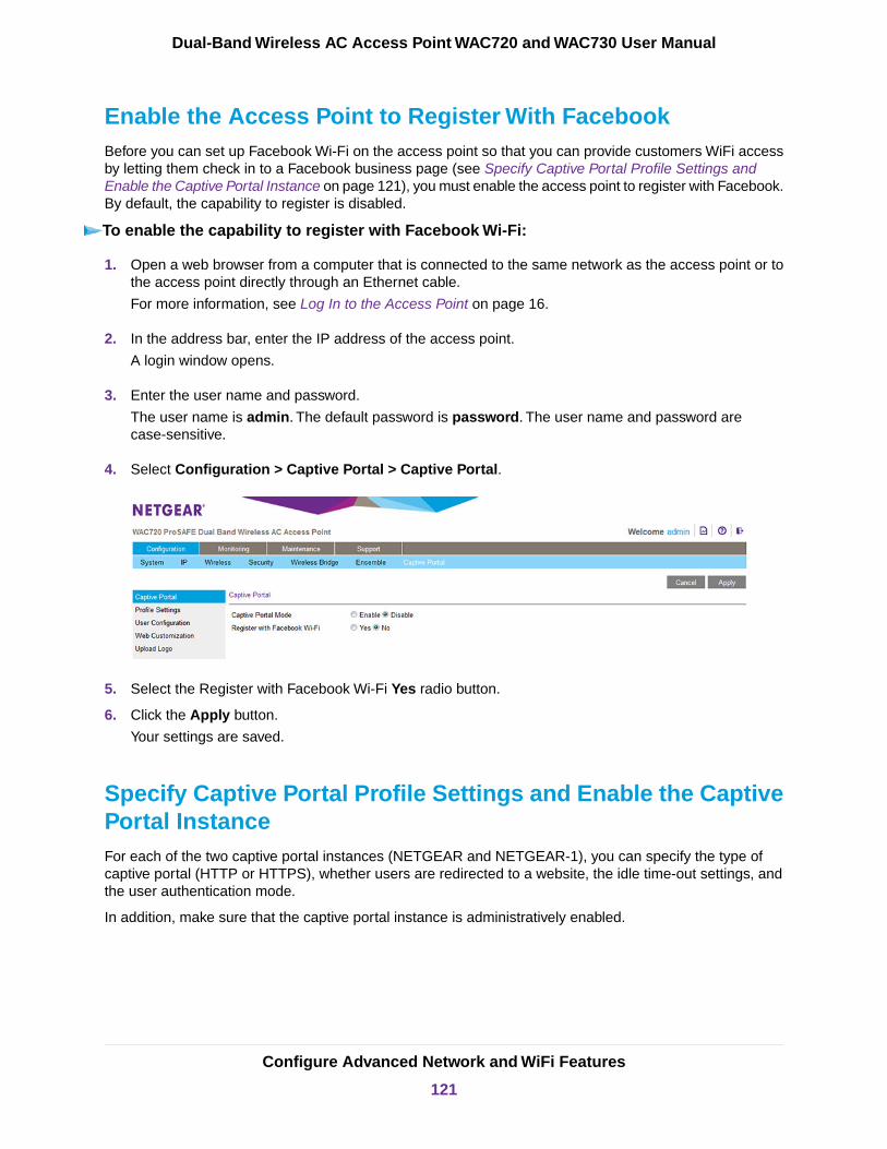
Enable the Access Point to Register With FacebookBefore you can set up Facebook Wi-Fi on the access point so that you can provide customers WiFi accessby letting them check in to a Facebook business page (see Specify Captive Portal Profile Settings andEnable the Captive Portal Instance on page 121), you must enable the access point to register with Facebook.By default, the capability to register is disabled.
To enable the capability to register with Facebook Wi-Fi:
1. Open a web browser from a computer that is connected to the same network as the access point or tothe access point directly through an Ethernet cable.
For more information, see Log In to the Access Point on page 16.
2. In the address bar, enter the IP address of the access point.
A login window opens.
3. Enter the user name and password.
The user name is admin. The default password is password. The user name and password arecase-sensitive.
4. Select Configuration > Captive Portal > Captive Portal.
5. Select the Register with Facebook Wi-Fi Yes radio button.
6. Click the Apply button.
Your settings are saved.
Specify Captive Portal Profile Settings and Enable the CaptivePortal InstanceFor each of the two captive portal instances (NETGEAR and NETGEAR-1), you can specify the type ofcaptive portal (HTTP or HTTPS), whether users are redirected to a website, the idle time-out settings, andthe user authentication mode.
In addition, make sure that the captive portal instance is administratively enabled.
Configure Advanced Network and WiFi Features
121
Dual-Band Wireless AC Access Point WAC720 and WAC730 User Manual
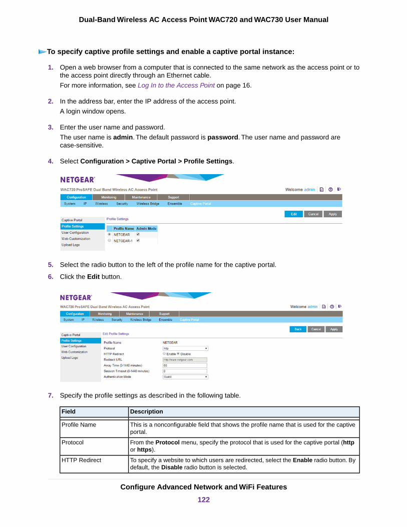
To specify captive profile settings and enable a captive portal instance:
1. Open a web browser from a computer that is connected to the same network as the access point or tothe access point directly through an Ethernet cable.
For more information, see Log In to the Access Point on page 16.
2. In the address bar, enter the IP address of the access point.
A login window opens.
3. Enter the user name and password.
The user name is admin. The default password is password. The user name and password arecase-sensitive.
4. Select Configuration > Captive Portal > Profile Settings.
5. Select the radio button to the left of the profile name for the captive portal.
6. Click the Edit button.
7. Specify the profile settings as described in the following table.
DescriptionField
This is a nonconfigurable field that shows the profile name that is used for the captiveportal.
Profile Name
From the Protocol menu, specify the protocol that is used for the captive portal (httpor https).
Protocol
To specify a website to which users are redirected, select the Enable radio button. Bydefault, the Disable radio button is selected.
HTTP Redirect
Configure Advanced Network and WiFi Features
122
Dual-Band Wireless AC Access Point WAC720 and WAC730 User Manual
(Continued)
DescriptionField
If the Enable radio button is selected, enter the website or enter the IP v4 or IPv6address:
• IPv4 address. Must be in a format similar to http://xxx.xxx.xxx.xxx, for example,http://192.0.2.10.
• IPv6 address. Must be in a format similar tohttp://[xxxx:xxxx:xxxx:xxxx::xxxx:xxxx:xxxx: xxxx], for example,http://[2001:DB8::CAD5:7D91].
Redirect URL
Enter the period during which a user remains in the authenticated client list after theuser disassociates from the captive portal. If the period expires before the user attemptsto reauthenticate, the entry is removed from the authenticated client list.
The range is from 0 to 1440 minutes. The default period is 60 minutes.
Away Time (0-1440minutes)
Enter the period after which a captive portal session is automatically terminated and auser is logged out.
The range is from 0 to 1440 minutes. The default value is 0, which effectively disablesthe session time-out.
If you select Facebook Wi-Fi from the Authentication Mode menu(see Step 8), the session time-out overrides the session length valuethat you configure on the Facebook Wi-Fi Configuration page.
Note
Session Timeout (0-1440minutes)
8. From the Authentication Mode menu, select the authentication database against which captive portalusers are authenticated:
• Guest. Although guest users must enter a name, they are not authenticated for the captive portal.These users are not in the local database or the database on a RADIUS server.This mode is suitablefor an open network, for example, a hotspot with free access. However, if the network is not open,users must enter the passphrase or password that is associated with the WiFi security profile (seeConfigure and Enable WiFi Security Profiles on page 39).
• Local. Users are authenticated against the local database.You must add each user to the localdatabase (see Add User Accounts to the Local Database for Captive Portal Access on page 126).This mode is suitable for a secured WiFi network with returning users.
• Radius. Users are authenticated against the database on a RADIUS server. The user informationmust be in the database. This mode is suitable for a secured WiFi network with returning users.Specify the following settings so that the access point can reach the RADIUS server
- Radius IP Network. From the menu, select ipv4 or ipv6.
- Primary Authentication IP. Enter the IPv4 or IPv6 address for the primary RADIUS server.
- Secondary Authentication IP. Enter the IPv4 or IPv6 address for the secondary RADIUSserver. This setting is optional.
Configure Advanced Network and WiFi Features
123
Dual-Band Wireless AC Access Point WAC720 and WAC730 User Manual

- Primary Authentication Key. Enter the shared key that is used between the access point andthe primary RADIUS server during authentication.
- Secondary Authentication Key. Enter the shared key that is used between the access pointand the secondary RADIUS server during authentication. This setting is required only if youspecify a secondary RADIUS server.
• Facebook Wi-Fi.You can set up Facebook Wi-Fi on the access point so that you can providecustomers WiFi access by letting them check in to a Facebook business page. For more information,see Set Up Facebook Wi-Fi for a Captive Portal Profile on page 124.
9. Click the Apply button.
Your settings are saved.
10. Click the Back button.
The Profile Settings page displays again.
11. Make sure that the Admin Mode check box is selected for the selected captive portal instance so thatthe instance is administratively enabled and becomes available after you select it for a WiFi profile (seeConfigure and Enable WiFi Security Profiles on page 39).
If the Admin Mode check box is cleared, the captive portal instance is administratively disabled anddoes not become available after you select the instance for a WiFi security profile.
12. Click the Apply button.
The captive portal instance is administratively enabled.
Set Up Facebook Wi-Fi for a Captive Portal ProfileYou can set up a captive portal on a WiFi network to offer free access through check-in to a Facebookbusiness page. Make sure that the capability to register with Facebook is enabled (see Enable the AccessPoint to Register With Facebook on page 121).
ATTENTION:
After you add a captive portal for Facebook Wi-Fi, the associated portal splash pagemight not open under some circumstances, allowing users Internet access withoutlogging in. This security limitation is implemented by Facebook Wi-Fi, not byNETGEAR. If a user opens a browser and attempts to access a website over HTTP(by default, over port 80), the user is directed to the splash page. However, if a userattempts to access a website that does not use HTTP, the splash page might notopen and the user can access the website without logging in. For example, thissituation occurs if a user opens a browser and accesses a secure website over HTTPS(by default, over port 443), or if an application uses HTTPS to send traffic to theInternet.
Configure Advanced Network and WiFi Features
124
Dual-Band Wireless AC Access Point WAC720 and WAC730 User Manual

To set up Facebook Wi-Fi:
1. Open a web browser from a computer that is connected to the same network as the access point or tothe access point directly through an Ethernet cable.
For more information, see Log In to the Access Point on page 16.
2. In the address bar, enter the IP address of the access point.
A login window opens.
3. Enter the user name and password.
The user name is admin. The default password is password. The user name and password arecase-sensitive.
4. Select Configuration > Captive Portal > Profile Settings.
The Profile Settings page displays.
5. Select the radio button to the left of the WiFi network name (SSID) with which you want to associatethe captive portal.
6. Click the Edit button.
The Edit Profile Settings page displays.
7. From the Authentication Mode menu, select Facebook Wi-Fi.
The page adjust and displays the Add Page button.
8. Click the Add Page button.
The Facebook Login page displays.
9. Log in to a Facebook account.
10. From the Select a Page menu, select a Facebook business page.
11. Select the bypass mode option:
• To allow customers to skip check-in, select the Skip check-in link radio button.
Configure Advanced Network and WiFi Features
125
Dual-Band Wireless AC Access Point WAC720 and WAC730 User Manual
If you enable this option, users can either check in to the selected Facebook business page or skipthe check-in.
• To require users to enter a WiFi code before they can gain WiFi access, select the Require Wi-Ficode radio button and type a WiFi code in the field that displays.If you enable this option, users can either check in to the selected Facebook business page or skipthe check-in by using the WiFi code.
12. From the Session Length menu, select the period after which users are automatically logged out.
13. To add terms of service to the Facebook check-in page, select the Terms of Service check box andtype or copy the terms of service.
14. Click the Save Settings button.
The Facebook Wi-Fi settings are saved.
The name of the selected Facebook business page displays on the Facebook Wi-Fi configuration page,along with the Change Page button, which lets you replace the selected Facebook business page withanother one.
15. On the Edit Profile Settings page, click the Apply button.
Your settings are saved.
16. Click the Back button.
The Profile Settings page displays again.
17. Make sure that the Admin Mode check box is selected for the selected captive portal instance so thatthe instance is administratively enabled and becomes available after you select it for a WiFi profile (seeConfigure and Enable WiFi Security Profiles on page 39).
If the Admin Mode check box is cleared, the captive portal instance is administratively disabled anddoes not become available after you select the instance for a WiFi security profile.
18. Click the Apply button.
The captive portal instance is administratively enabled.
Add User Accounts to the Local Database for Captive PortalAccess
You do not need to add users accounts to the local user database if the authenticationfor a captive portal instance is configured for guest access or uses a RADIUS server.
Note
If a captive portal instance uses the local database for authentication (see Specify Captive Portal ProfileSettings and Enable the Captive Portal Instance on page 121), you must add a user account to the localdatabase for each user that you want to grant access through the captive portal.
A user who wants to log in through the captive portal must use the user name and password that you assignto him or her.
Configure Advanced Network and WiFi Features
126
Dual-Band Wireless AC Access Point WAC720 and WAC730 User Manual
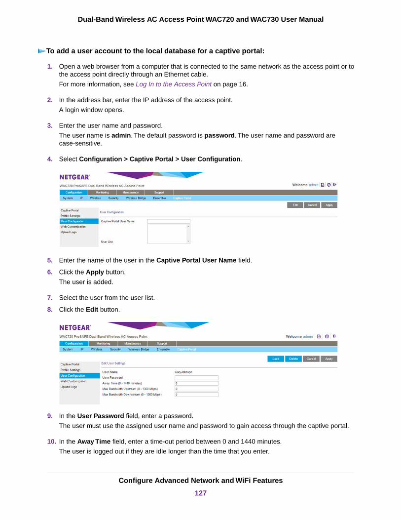
To add a user account to the local database for a captive portal:
1. Open a web browser from a computer that is connected to the same network as the access point or tothe access point directly through an Ethernet cable.
For more information, see Log In to the Access Point on page 16.
2. In the address bar, enter the IP address of the access point.
A login window opens.
3. Enter the user name and password.
The user name is admin. The default password is password. The user name and password arecase-sensitive.
4. Select Configuration > Captive Portal > User Configuration.
5. Enter the name of the user in the Captive Portal User Name field.
6. Click the Apply button.
The user is added.
7. Select the user from the user list.
8. Click the Edit button.
9. In the User Password field, enter a password.
The user must use the assigned user name and password to gain access through the captive portal.
10. In the Away Time field, enter a time-out period between 0 and 1440 minutes.
The user is logged out if they are idle longer than the time that you enter.
Configure Advanced Network and WiFi Features
127
Dual-Band Wireless AC Access Point WAC720 and WAC730 User Manual

11. In the Max Bandwidth Upstream field, enter the maximum upstream bandwidth allowed to the user,in megabits per second.
This setting is optional.
12. In the Max Bandwidth Downstream field, enter the maximum downstream bandwidth allowed to theuser, in megabits per second.
This setting is optional.
13. Click the Apply button.
Your settings are saved.
Upload a Custom LogoIf you want to use a custom logo on the splash page for captive portal, you must upload it before you canselect it. If you do not need to use a custom logo, skip this procedure.
To upload a custom logo:
1. Open a web browser from a computer that is connected to the same network as the access point or tothe access point directly through an Ethernet cable.
For more information, see Log In to the Access Point on page 16.
2. In the address bar, enter the IP address of the access point.
A login window opens.
3. Enter the user name and password.
The user name is admin. The default password is password. The user name and password arecase-sensitive.
4. Select Configuration > Captive Portal > Upload Logo.
5. Click the Choose File button.
6. Navigate to and select the logo file.
The file name including the file extension (.jpg or .gif) is limited to 32 characters and the file sizecannot exceed 5 KB.
7. Click the Upload button.
The logo file is uploaded and is selectable when you configure the splash page for a captive portal.
Configure Advanced Network and WiFi Features
128
Dual-Band Wireless AC Access Point WAC720 and WAC730 User Manual
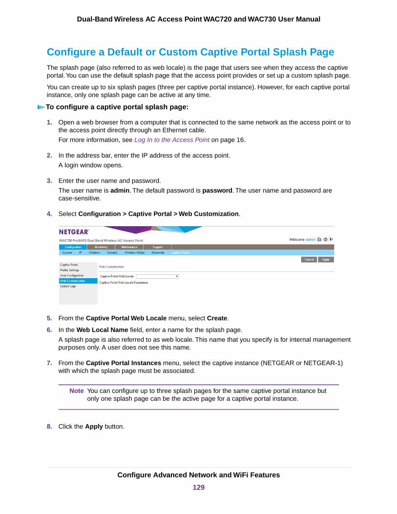
Configure a Default or Custom Captive Portal Splash PageThe splash page (also referred to as web locale) is the page that users see when they access the captiveportal.You can use the default splash page that the access point provides or set up a custom splash page.
You can create up to six splash pages (three per captive portal instance). However, for each captive portalinstance, only one splash page can be active at any time.
To configure a captive portal splash page:
1. Open a web browser from a computer that is connected to the same network as the access point or tothe access point directly through an Ethernet cable.
For more information, see Log In to the Access Point on page 16.
2. In the address bar, enter the IP address of the access point.
A login window opens.
3. Enter the user name and password.
The user name is admin. The default password is password. The user name and password arecase-sensitive.
4. Select Configuration > Captive Portal > Web Customization.
5. From the Captive Portal Web Locale menu, select Create.
6. In the Web Local Name field, enter a name for the splash page.
A splash page is also referred to as web locale. This name that you specify is for internal managementpurposes only. A user does not see this name.
7. From the Captive Portal Instances menu, select the captive instance (NETGEAR or NETGEAR-1)with which the splash page must be associated.
You can configure up to three splash pages for the same captive portal instance butonly one splash page can be the active page for a captive portal instance.
Note
8. Click the Apply button.
Configure Advanced Network and WiFi Features
129
Dual-Band Wireless AC Access Point WAC720 and WAC730 User Manual
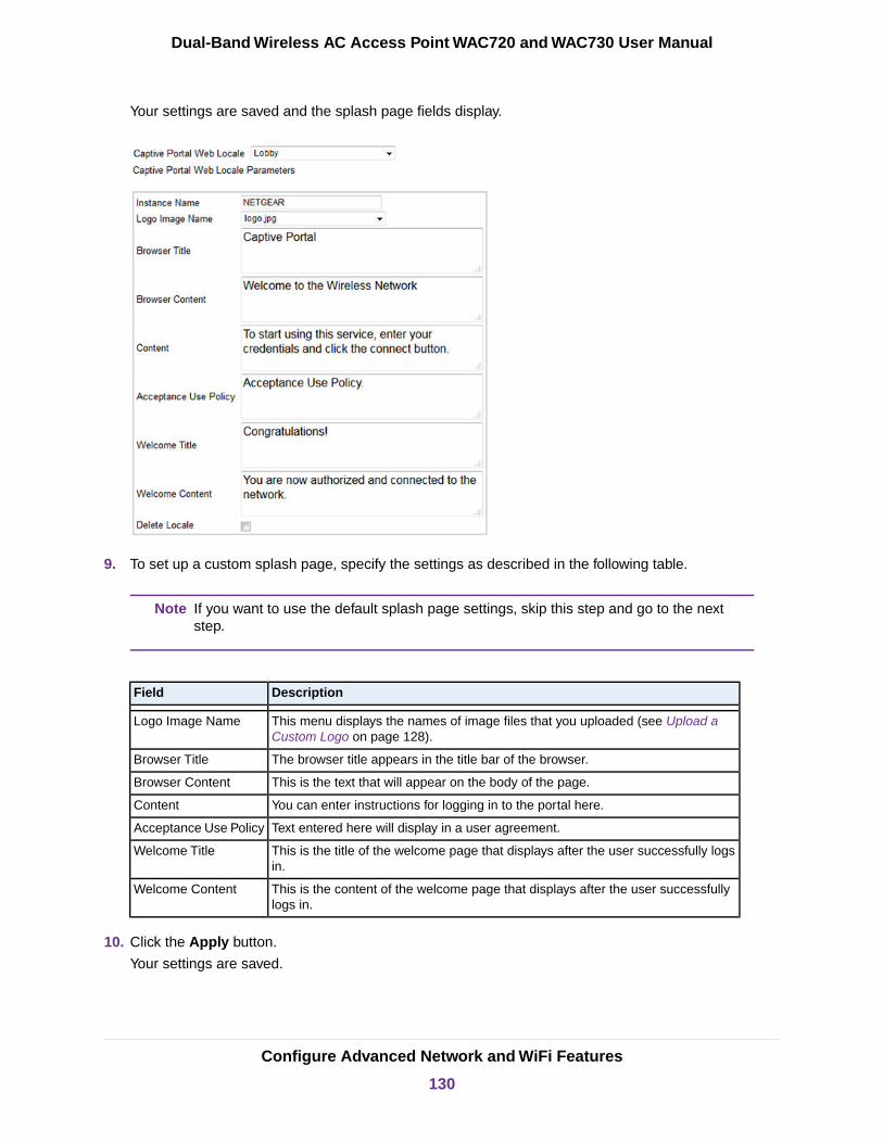
Your settings are saved and the splash page fields display.
9. To set up a custom splash page, specify the settings as described in the following table.
If you want to use the default splash page settings, skip this step and go to the nextstep.
Note
DescriptionField
This menu displays the names of image files that you uploaded (see Upload aCustom Logo on page 128).
Logo Image Name
The browser title appears in the title bar of the browser.Browser Title
This is the text that will appear on the body of the page.Browser Content
You can enter instructions for logging in to the portal here.Content
Text entered here will display in a user agreement.Acceptance Use Policy
This is the title of the welcome page that displays after the user successfully logsin.
Welcome Title
This is the content of the welcome page that displays after the user successfullylogs in.
Welcome Content
10. Click the Apply button.
Your settings are saved.
Configure Advanced Network and WiFi Features
130
Dual-Band Wireless AC Access Point WAC720 and WAC730 User Manual

Enable the Global Captive Portal ModeBy default, the global captive portal mode is disabled on the access point. If you do not want to use a captiveportal, leave the mode disabled because it globally disables captive portals on the access point.
If you do want to use a captive portal, enable the global captive portal mode.You must still enable eachindividual captive portal instance before it can become accessible.
To enable the global captive portal mode:
1. Open a web browser from a computer that is connected to the same network as the access point or tothe access point directly through an Ethernet cable.
For more information, see Log In to the Access Point on page 16.
2. In the address bar, enter the IP address of the access point.
A login window opens.
3. Enter the user name and password.
The user name is admin. The default password is password. The user name and password arecase-sensitive.
4. Select Configuration > Captive Portal > Captive Portal.
5. Select the Enable radio button.
6. Click the Apply button.
Your settings are saved.
IMPORTANT:Before you can use a captive portal that you configured, you must select thecaptive portal instance for a WiFi security profile (see Configure and EnableWiFi Security Profiles on page 39). After you do so, the WiFi network that isassociated with the WiFi security profile becomes accessible only throughthe captive portal.
Configure Advanced Network and WiFi Features
131
Dual-Band Wireless AC Access Point WAC720 and WAC730 User Manual

Configure WiFi Bridging
The access point supports a wireless distribution system (WDS) that lets you build large bridged WiFinetworks.
Point-to-Point Bridge and Point-to-Multipoint BridgeYou can set up a single point-to-point bridge or create a point-to-multipoint bridge by setting up to fourpoint-to-point bridges with your access point functioning as the master:
• WiFi point-to-point bridge. The access point communicates with another bridge-mode access pointand with WiFi clients.You can use WPA2-PSK to secure the communication. The following figure showsan example in which two access points (APs) function in point-to-point bridge mode.
Figure 7. Point-to-point WiFi network
• WiFi point-to-multipoint bridge. The access point is the master for a group of bridge-mode accesspoints.You can configure up to four WiFi bridges.The other bridge-mode WiFi access points must be set to point-to-point bridge mode, using the MACaddress of the your access point (that is, the master). Rather than communicating directly with eachother, all other bridge-mode access points send their traffic to the master access point.You can useWPA2-PSK to secure the communication.
Figure 8. Point-to-multipoint WiFi network
Configure Advanced Network and WiFi Features
132
Dual-Band Wireless AC Access Point WAC720 and WAC730 User Manual

Configure a WiFi BridgeIn bridge mode, the access point communicates with one or more other bridge-mode access points. Bydefault, the connection is an open system but you can use WPA2-PSK security to protect this communication.
You cannot configure WiFi bridging when automatic channel selection is enabled. Onthe basic Wireless Settings page, make sure that Auto is not selected from the Channel/ Frequency menu (see Configure the Basic WiFi Settings on page 24).
Note
To configure a WiFi bridge:
1. Open a web browser from a computer that is connected to the same network as the access point or tothe access point directly through an Ethernet cable.
For more information, see Log In to the Access Point on page 16.
2. In the address bar, enter the IP address of the access point.
A login window opens.
3. Enter the user name and password.
The user name is admin. The default password is password. The user name and password arecase-sensitive.
4. Configure the access point (AP1 on LAN Segment 1 in the previous figures) as a point-to-point bridge:
a. Select Configuration > Wireless Bridge.
b. Select the Enable Wireless Bridging check box.
c. Click the Apply button.
Your settings are saved and the WiFi bridging feature is enabled. However, you still must configureone or more WiFi bridges and enable them.
You can configure up to four profiles. By default, a profile does not provide security (it is an opensystem), but you can configure WPA2-PSK. The Local MAC Address field is a nonconfigurablefield that shows the MAC address of the access point.
d. Select the radio button for a profile.
Configure Advanced Network and WiFi Features
133
Dual-Band Wireless AC Access Point WAC720 and WAC730 User Manual
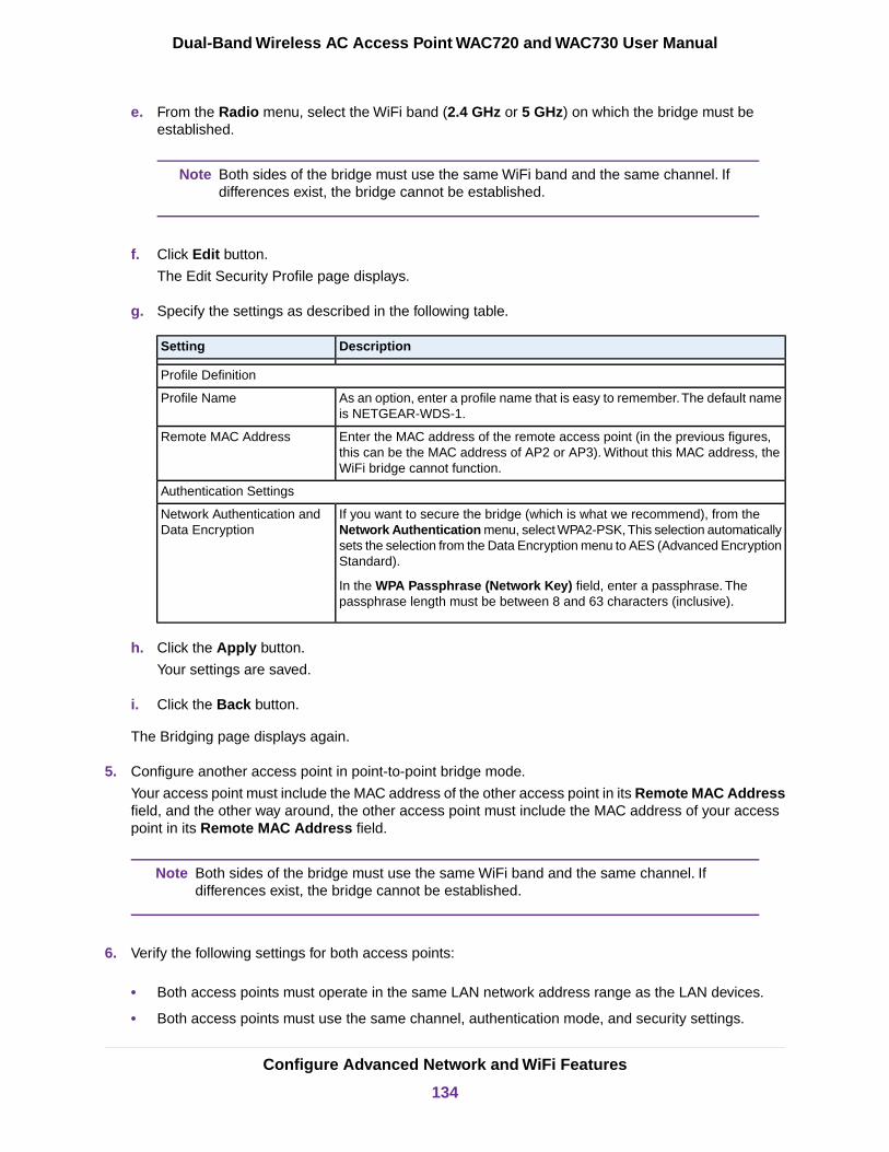
e. From the Radio menu, select the WiFi band (2.4 GHz or 5 GHz) on which the bridge must beestablished.
Both sides of the bridge must use the same WiFi band and the same channel. Ifdifferences exist, the bridge cannot be established.
Note
f. Click Edit button.
The Edit Security Profile page displays.
g. Specify the settings as described in the following table.
DescriptionSetting
Profile Definition
As an option, enter a profile name that is easy to remember.The default nameis NETGEAR-WDS-1.
Profile Name
Enter the MAC address of the remote access point (in the previous figures,this can be the MAC address of AP2 or AP3). Without this MAC address, theWiFi bridge cannot function.
Remote MAC Address
Authentication Settings
If you want to secure the bridge (which is what we recommend), from theNetwork Authentication menu, select WPA2-PSK, This selection automaticallysets the selection from the Data Encryption menu to AES (Advanced EncryptionStandard).
In the WPA Passphrase (Network Key) field, enter a passphrase. Thepassphrase length must be between 8 and 63 characters (inclusive).
Network Authentication andData Encryption
h. Click the Apply button.
Your settings are saved.
i. Click the Back button.
The Bridging page displays again.
5. Configure another access point in point-to-point bridge mode.
Your access point must include the MAC address of the other access point in its Remote MAC Addressfield, and the other way around, the other access point must include the MAC address of your accesspoint in its Remote MAC Address field.
Both sides of the bridge must use the same WiFi band and the same channel. Ifdifferences exist, the bridge cannot be established.
Note
6. Verify the following settings for both access points:
• Both access points must operate in the same LAN network address range as the LAN devices.
• Both access points must use the same channel, authentication mode, and security settings.
Configure Advanced Network and WiFi Features
134
Dual-Band Wireless AC Access Point WAC720 and WAC730 User Manual

7. Go back to the Bridging page on your access point and select the Enable check box for the profile.
8. Click the Apply button.
Your settings are saved.
9. Enable bridging on the other access point.
10. Verify connectivity across the LAN segments.
A computer on either LAN segment must be able to connect to the Internet and share files and printersof any other computers or servers on the other LAN segment.
11. To set up a point-to-multipoint WiFi network, repeat Step 4 through Step 10 for another profile andanother access point.
In point-to-multipoint WiFi network, your access point becomes the master for all WiFi bridges. For eachaccess point that you want the master to be able to connect to, you must configure a security profilewith a unique name and the MAC address of the access point.You can configure up to four such securityprofiles (NETGEAR-WDS-1, NETGEAR-WDS-2, and so on).
You can extend the range of a WiFi bridge with NETGEAR WiFi antenna accessories.Note
Configure Advanced Network and WiFi Features
135
Dual-Band Wireless AC Access Point WAC720 and WAC730 User Manual

6Troubleshooting
This chapter provides information about troubleshooting the access point. After each problem description,instructions are given to help you diagnose and solve the problem.
For the common problems listed, go to the section indicated.
• Is the access point on?Go to Troubleshoot the Basic Functions on page 137.
• Did I connected the access point correctly?Go to Troubleshoot the Basic Functions on page 137.
• I cannot access the Internet or the LAN.Go to You Cannot Access the Internet or the LAN From a WiFi Computer on page 138.
• I cannot access the access point from a browser.Go to You Cannot Configure the Access Point From a Browser on page 139.
• A time-out occurs.Go to When You Enter a URL or IP Address a Time-Out Error Occurs on page 140.
• Problems with the LAN connection occur.Go to Troubleshoot a TCP/IP Network Using the Ping Utility on page 140.
• I cannot remember the access point’s configuration password.Go to Change the Administrator Password on page 72.
• I want to clear the configuration and start over again.Go to Restore the Access Point to the Factory Default Settings on page 69.
• The date or time is not correct.Go to Problems With Date and Time on page 141.
The access point provides a packet capture tool that enables you to perform problem diagnoses. For informationabout how to use this tool, see Use the Packet Capture Tool on page 142.
136

Troubleshoot the Basic Functions
The following sections describe how you can troubleshoot the basic functions of the access point:
• Verify the Correct Sequence of Events at Startup on page 137
• No LEDs Are Lit on the Access Point on page 137
• The Active LED or the LAN LED Is Not Lit on page 138
• The WLAN LED Does Not Light on page 138
For descriptions of the LEDs, see Top Panel on page 9.Note
Verify the Correct Sequence of Events at Startup
• After you turn on power to the access point, check that the following sequence of events occurs:
• The Power/Test LED is first steady amber, then goes off, and then blinks green before turning steadygreen after about 45 seconds.
• The Active LED is lit or blinks green when Ethernet traffic is detected.
• The LAN LED indicates the LAN speed: green for 1000 Mbps, amber for 100 Mbps, and no light for 10Mbps.
• The WLAN LED is lit or blinks green when the WiFi LAN (WLAN) is ready.
If any of these conditions does not occur, see the appropriate following section.
No LEDs Are Lit on the Access PointIt takes a few seconds for the Power LED to light. Wait a minute and check the Power LED status on theaccess point.
If the access point is not receiving power, do the following:
• If you use one or more PoE switches to provide power to the access point, check these items:
- Make sure that the Ethernet cables between the access point and the PoE switches are correctlyconnected at both ends.
- Make sure that the power cords of the PoE switches are plugged into working power outlets orpower strips.
- Make sure that the PoE switches are functioning normally.
• If you use a power cord to provide power to the access point, check these items:
Troubleshooting
137
Dual-Band Wireless AC Access Point WAC720 and WAC730 User Manual
- Make sure that the power cord is connected to the access point.
- Make sure that the power adapter is connected to a functioning power outlet. If it is in a power strip,make sure that the power strip is turned on. If it is plugged directly into the wall, verify that it is nota switched outlet.
- Make sure that you are using the correct NETGEAR power adapter that is supplied with your accesspoint.
The Active LED or the LAN LED Is Not LitA hardware connection problem occurs.
Check these items:
• Make sure that the cable connectors are securely plugged in at the access point and the networkdevice—hub, (PoE) switches, or router.
• Make sure that the connected device is turned on.
• Make sure that the correct cable is used. Use a standard Category 5 Ethernet patch cable. If the networkdevice has Auto Uplink (MDI/MDIX) ports, you can use either a crossover cable or a normal patch cable.
The WLAN LED Does Not LightThe access point’s antenna is not working.
Check these items:
• If the WLAN LED remains off, either disconnect the cables to the PoE switches and then reconnectthem again, or disconnect the adapter from its power source and then plug it in again.
• Make sure that optional external antennas are tightly connected to the access point.
Contact NETGEAR technical support if the WLAN LED remains off.
You Cannot Access the Internet or the LAN From a WiFiComputer
A configuration problem occurred.
Check these items:
• Maybe you did not restart the WiFi computer to allow TCP/IP changes to take effect. If so, restart thecomputer.
• The WiFi computer might not include the correct TCP/IP settings to communicate with the network.Restart the computer and check that TCP/IP is set up correctly for that network. In Windows, the usualsetting for Network Properties is to obtain an IP address automatically.
• The access point’s default values might not work with your network. Check the access point’s defaultconfiguration against the configuration of other devices in your network.
Troubleshooting
138
Dual-Band Wireless AC Access Point WAC720 and WAC730 User Manual

• Make sure that the SSID, network authentication, and data encryption settings of the WiFi computerare the same as those of the access point.
• Ping the IP address of the access point to verify that a WiFi connection exists between the WiFi computerand the access point. If the ping fails, check the network configuration (for the access point, see Configurethe IPv4 Settings on page 23).
• Ping the default gateway to verify that a path exists from the WiFi computer to the default gateway. Ifthe ping fails, check the network configuration or call the Internet service provider (ISP).
You Cannot Configure the Access Point From a Browser
Check these items:
• The access point is correctly installed, it is powered on, and LAN connections are okay. Check to seethat the Active LED and LAN LED are on to verify that the Ethernet connection is okay.
• If your computer uses a fixed (static) IP address, ensure that it is using an IP address in the range ofthe access point. The access point’s default IP address is 192.168.0.100, and its subnet mask is255.255.255.0, with DHCP disabled. Make sure that your network configuration settings are correct.
• If you are using the NetBIOS name of the access point to connect, ensure that your computer and theaccess point are on the same network segment or that your network includes a WINS server.
• If your computer is set to obtain an IP address automatically (DHCP client), restart it.
• Make sure that Java, JavaScript, or ActiveX is enabled in your browser. If you are using Internet Explorer,click the Refresh button to be sure that the Java applet is loaded.
• Try quitting the browser, clearing the cache, deleting the cookies, and launching the browser again.
• Make sure that you are using the correct login information. The factory default login name is admin,and the password is password. Make sure that Caps Lock is off when entering this information.
If the access point does not save changes that you made in the local browser interface, check the following:
• When entering configuration settings, be sure to click the Apply button before moving to another pageor tab, or your changes are lost.
• Click the Refresh or Reload button in the web browser. The changes might occur, but the web browsermight be caching the old configuration.
Troubleshooting
139
Dual-Band Wireless AC Access Point WAC720 and WAC730 User Manual
When You Enter a URL or IP Address a Time-Out ErrorOccurs
A number of things could be causing this situation. Try the following troubleshooting steps:
• Check to see whether other computers on the LAN work correctly. If they do, ensure that your computer’sTCP/IP settings are correct. If you use a fixed (static) IP address, check the subnet mask, defaultgateway, DNS, and IP addresses of the access point (see Configure the IPv4 Settings on page 23).
• If the computer is configured correctly but still not working, ensure that the access point is connectedand turned on. Access it and check its settings. If you cannot connect to the access point, check theLAN and power connections.
• If the access point is configured correctly, check your Internet connection (for example, your cablemodem) to make sure that it is working correctly.
Troubleshoot a TCP/IP Network Using the Ping Utility
Most TCP/IP terminal devices and routers contain a ping utility that sends an echo request packet to thedesignated device. The device then responds with an echo reply.You can easily troubleshoot a TCP/IPnetwork by using the ping utility in your computer, as described in the following sections:
• Test the LAN Path to Your Access Point on page 140
• Test the Path from Your Computer to a Remote Device on page 141
Test the LAN Path to Your Access PointYou can ping the access point from your computer to verify that the LAN path to your access point is set upcorrectly.
To ping the access point from a computer running Windows:
1. From the Windows toolbar, click the Start button, and select Run.
2. In the field provided, type ping followed by the IP address of the access point, as in this example:
ping 192.168.0.100
3. Click the OK button.
A message like the following one displays:
Pinging <IP address> with 32 bytes of data
If the path is working, you see this message:
Reply from < IP address >: bytes=32 time=NN ms TTL=xxx
If the path is not working, you see this message:
Request timed out
Troubleshooting
140
Dual-Band Wireless AC Access Point WAC720 and WAC730 User Manual
If the path is not functioning correctly, one of the following problems could be occurring:
• Make sure that the Active LED and LAN LED are on. If one or both of these LEDs are off, followthe instructions in The Active LED or the LAN LED Is Not Lit on page 138.
• Check to see that the corresponding link LEDs are on for your network interface card and for thehub ports (if any) that are connected to your workstation and access point.
• Wrong network configuration:
- Verify that the Ethernet card driver software and TCP/IP software are both installed andconfigured on your computer.
- Verify that the IP address for your access point and your workstation are correct and that theaddresses are on the same subnet.
Test the Path from Your Computer to a Remote DeviceAfter verifying that the LAN path works correctly, test the path from your computer to a remote device.
1. From the Windows toolbar, click the Start button, and select Run.
2. In the field provided, enter ping -n 10 IP address.
where IP address is the IP address of a remote device such as the DNS server of your ISP.
If the path is functioning correctly, replies as in Test the LAN Path to Your Access Point on page 140display. If you do not receive replies, do the following:
• Check to see that the IP address of your access point is listed as the IP address of the default routerin your computer. If the IP configuration of your computer is assigned by DHCP, this information isnot visible in your computer’s Network Control Panel. Verify that the IP address of the access pointis listed as the IP address of the default router.
• Check to see that the network address of your computer (the portion of the IP address specified bythe netmask) is different from the network address of the remote device.
• Check to see that your cable or DSL modem is connected and functioning.
• If your ISP assigned a host name to your computer, enter that host name as the account name onthe basis General system settings page (see Configure Basic General System Settings on page20).
Problems With Date and Time
The Time Settings page that is accessible through the Configuration > System > Basic > Time menu choicesdisplays the current date and time of day.The access point uses the Network Time Protocol (NTP) to obtainthe current time from a network time server on the Internet that you specify in the Time Settings page (seeConfigure Basic General System Settings on page 20). Each entry on the Logs page is stamped with thedate and time of day. Problems with the date and time function can include the following:
• Date and time shown is Fri Dec 31 00:00:00 1999 or a similar incorrect date and time. Cause: Theaccess point did not yet successfully reach the network time server. Check to see that your Internet
Troubleshooting
141
Dual-Band Wireless AC Access Point WAC720 and WAC730 User Manual
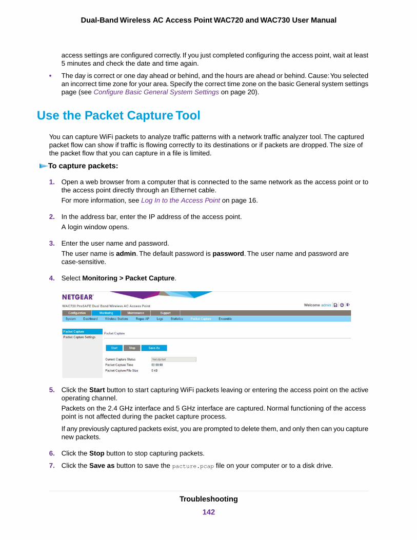
access settings are configured correctly. If you just completed configuring the access point, wait at least5 minutes and check the date and time again.
• The day is correct or one day ahead or behind, and the hours are ahead or behind. Cause:You selectedan incorrect time zone for your area. Specify the correct time zone on the basic General system settingspage (see Configure Basic General System Settings on page 20).
Use the Packet Capture Tool
You can capture WiFi packets to analyze traffic patterns with a network traffic analyzer tool. The capturedpacket flow can show if traffic is flowing correctly to its destinations or if packets are dropped. The size ofthe packet flow that you can capture in a file is limited.
To capture packets:
1. Open a web browser from a computer that is connected to the same network as the access point or tothe access point directly through an Ethernet cable.
For more information, see Log In to the Access Point on page 16.
2. In the address bar, enter the IP address of the access point.
A login window opens.
3. Enter the user name and password.
The user name is admin. The default password is password. The user name and password arecase-sensitive.
4. Select Monitoring > Packet Capture.
5. Click the Start button to start capturing WiFi packets leaving or entering the access point on the activeoperating channel.
Packets on the 2.4 GHz interface and 5 GHz interface are captured. Normal functioning of the accesspoint is not affected during the packet capture process.
If any previously captured packets exist, you are prompted to delete them, and only then can you capturenew packets.
6. Click the Stop button to stop capturing packets.
7. Click the Save as button to save the pacture.pcap file on your computer or to a disk drive.
Troubleshooting
142
Dual-Band Wireless AC Access Point WAC720 and WAC730 User Manual
AConfigure the Access Point inBusiness Central Mode
This appendix provides information about the features that you can manually control while the access pointfunctions in Business Central mode (also referred to as cloud mode), that is, when the access point is cloudmanaged by the NETGEAR Business Central Wireless Manager (BCWM) application.
For information about the BCWM application, see the Business Central Wireless Manager Application QuickStart Guide and the Business Central Wireless Manager Application User Manual, both of which you candownload from downloadcenter.netgear.com.
The appendix includes the following sections:
• Enable Business Central Mode• Configure the IP and 802.1Q VLAN Settings in Business Central Mode• Reboot the Access Point in Business Central Mode• Reset the Access Point in Business Central Mode to Factory Default Settings• Upgrade Access Point Firmware in Business Central Mode• Configure MAC Authentication in Business Central Mode• Monitor the Access Point in Business Central Mode
For information about disabling Business Central mode, see Disable Business Central Modefor a Standalone Access Point on page 19.
Note
143

Enable Business Central Mode
By enabling Business Central mode, you can convert the access point from a standalone access point to astate in which the access point can be cloud managed by the NETGEAR BCWM application.
When the access point functions in Business Central mode, the local browser interface is a restricted interfacethat shows only the Configuration and Monitoring menu tabs with limited configuration options.
To enable Business Central mode:
1. Open a web browser from a computer that is connected to the same network as the access point or tothe access point directly through an Ethernet cable.
For more information, see Log In to the Access Point on page 16.
2. In the address bar, enter the IP address of the access point.
A login window opens.
3. Enter the user name and password.
The user name is admin. The default password is password. The user name and password arecase-sensitive.
4. Select Configuration > System > Basic > General.
5. Select the Business Central Enabled Yes radio button.
6. Click the Apply button.
The access point restarts with factory default settings but retains its IP configuration and managementVLAN.
The access point is now ready for cloud management with a restricted local browser interface.
Configure the Access Point in Business Central Mode
144
Dual-Band Wireless AC Access Point WAC720 and WAC730 User Manual
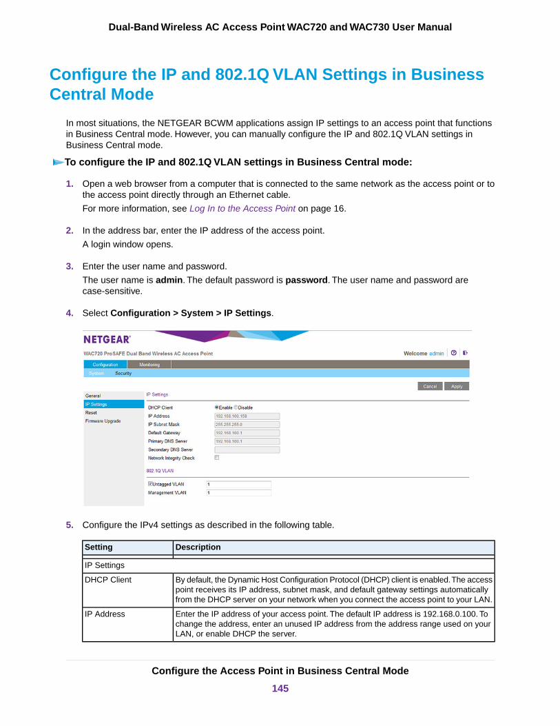
Configure the IP and 802.1Q VLAN Settings in BusinessCentral Mode
In most situations, the NETGEAR BCWM applications assign IP settings to an access point that functionsin Business Central mode. However, you can manually configure the IP and 802.1Q VLAN settings inBusiness Central mode.
To configure the IP and 802.1Q VLAN settings in Business Central mode:
1. Open a web browser from a computer that is connected to the same network as the access point or tothe access point directly through an Ethernet cable.
For more information, see Log In to the Access Point on page 16.
2. In the address bar, enter the IP address of the access point.
A login window opens.
3. Enter the user name and password.
The user name is admin. The default password is password. The user name and password arecase-sensitive.
4. Select Configuration > System > IP Settings.
5. Configure the IPv4 settings as described in the following table.
DescriptionSetting
IP Settings
By default, the Dynamic Host Configuration Protocol (DHCP) client is enabled.The accesspoint receives its IP address, subnet mask, and default gateway settings automaticallyfrom the DHCP server on your network when you connect the access point to your LAN.
DHCP Client
Enter the IP address of your access point. The default IP address is 192.168.0.100. Tochange the address, enter an unused IP address from the address range used on yourLAN, or enable DHCP the server.
IP Address
Configure the Access Point in Business Central Mode
145
Dual-Band Wireless AC Access Point WAC720 and WAC730 User Manual
(Continued)
DescriptionSetting
Enter the network number portion of an IP address. Unless you are implementingsubnetting, enter 255.255.0.0 as the subnet mask.
IP Subnet Mask
Enter the IP address of the ISP gateway to which the access point connects.Default Gateway
Enter the IP address of the primary and secondary DNS servers. A DNS server is a hoston the Internet that translates Internet names (such as www.netgear.com) to numeric IPaddresses.Typically your ISP transfers the IP address of one or two DNS servers to youraccess point during login. If the ISP does not transfer an address, you must obtain it fromthe ISP and enter it manually in this field.
Primary DNS Server
Secondary DNS Server
Select this check box to validate that the upstream link is active before allowing WiFiassociations. Ensure that the default gateway is configured.
Network Integrity Check
802.1Q VLAN
Select the Untagged VLAN check box to configure one VLAN as an untagged VLAN.By default, the Untagged VLAN check box is selected.
Specify a VLAN ID. The default VLAN ID is 1.
Untagged VLAN
Specify an ID for the VLAN from which the access point can be managed. The defaultVLAN ID is 1.
If you configure the management VLAN ID as 0 (zero), the access point can be managedover any VLAN, and frames that belong to the management VLAN are not tagged withan 802.1Q header when sent over the trunk.
Management VLAN
6. Click the Apply button.
Your settings are saved.
If you changed the IP address settings and want to log in to the access point again, you must use thenew IP address of the access point.
Reboot the Access Point in Business Central Mode
Situations might occur in which you must manually reboot the access point in Business Central mode.
To reboot the access point in Business Central mode:
1. Open a web browser from a computer that is connected to the same network as the access point or tothe access point directly through an Ethernet cable.
For more information, see Log In to the Access Point on page 16.
2. In the address bar, enter the IP address of the access point.
A login window opens.
3. Enter the user name and password.
The user name is admin. The default password is password. The user name and password arecase-sensitive.
4. Select Configuration > System > Reset.
Configure the Access Point in Business Central Mode
146
Dual-Band Wireless AC Access Point WAC720 and WAC730 User Manual

The Reboot AP and Restore Defaults page displays.
5. Select the Reboot Yes radio button.
By default, the Reboot No radio button is selected.
6. Click the Apply button.
The access point reboots.
The reboot process typically takes about one minute. When the Test LED turns off, wait a few moreseconds before doing anything with the access point.
Reset the Access Point in Business Central Mode toFactory Default Settings
Situations might occur in which you must manually reset the access point in Business Central mode tofactory default settings.
To reset the access point in Business Central mode to factory default settings:
1. Open a web browser from a computer that is connected to the same network as the access point or tothe access point directly through an Ethernet cable.
For more information, see Log In to the Access Point on page 16.
2. In the address bar, enter the IP address of the access point.
A login window opens.
3. Enter the user name and password.
The user name is admin. The default password is password. The user name and password arecase-sensitive.
4. Select Configuration > System > Reset.
The Reboot AP and Restore Defaults page displays.
5. Select the Restore to Factory Default Settings Yes radio button.
By default, the Restore to Factory Default Settings No radio button is selected.
6. Click the Apply button.
IMPORTANT:During the restoration process, do not try to go online, turn off the accesspoint, shut down the computer, or do anything else to the access point untilit finishes restarting!
7. Click the Apply button.
The access point is reset to the factory default settings.
During the restoration process, the access point automatically restarts.The restoration process typicallytakes about one minute. When the Test LED turns off, wait a few more seconds before doing anythingwith the access point.
Configure the Access Point in Business Central Mode
147
Dual-Band Wireless AC Access Point WAC720 and WAC730 User Manual

Upgrade Access Point Firmware in Business Central Mode
In most situations, the NETGEAR BCWM application upgrades firmware to an access point that functionsin Business Central mode. However, situations might occur in which you must manually upgrade the firmwareon the access point in Business Central mode.
To upgrade the access point firmware in Business Central mode if you already downloadedthe firmware file:
1. Open a web browser from a computer that is connected to the same network as the access point or tothe access point directly through an Ethernet cable.
For more information, see Log In to the Access Point on page 16.
2. In the address bar, enter the IP address of the access point.
A login window opens.
3. Enter the user name and password.
The user name is admin. The default password is password. The user name and password arecase-sensitive.
4. Select Configuration > System > Reset.
The Firmware Upgrade page displays.
5. Click the Browse button and locate and select the firmware upgrade file.
The firmware upgrade file is a .tar file.
6. Click the Apply button.
WARNING:When uploading firmware to the access point, do not interrupt the web browserby closing the page, clicking a link, or loading a new page. If the browser isinterrupted, the upload might fail, corrupt the firmware, and render the accesspoint inoperable.
During the upgrade process, the access point automatically restarts. The upgrade process typicallytakes several minutes. When the Test LED turns off, wait a few more seconds before doing anythingwith the access point.
7. Verify that the new firmware file was installed by selecting Configuration > General.
The Business Central Settings and Access Point Information page displays. The firmware version isshown in the Access Point Information section of the page.
Configure MAC Authentication in Business Central Mode
All WiFi networks for an access point that functions in Business Central mode are managed by the BCWMapplication. Any changes that you make to a WiFi security profile must be made through the BCWMapplication, with one exception: On the access point in Business Central mode, you can set up a MACaddress filter profile using the local MAC address database and assign that profile to a cloud-managed WiFi
Configure the Access Point in Business Central Mode
148
Dual-Band Wireless AC Access Point WAC720 and WAC730 User Manual
network.You perform those actions on the access point in Business Central mode itself rather than throughthe BCWM application.
For increased security, you can restrict access to an SSID by allowing access to only specific computers orWiFi stations based on their MAC addresses.You can restrict access to only trusted computers so thatunknown computers cannot connect over WiFi to the access point. MAC address filtering adds an obstacleagainst unwanted access to your network, but the data broadcast over the WiFi link is fully exposed if youdo not also implement WiFi security.
Before you can implement MAC address filtering, you must set up one or more MAC address filter profiles(which is described in this section) and then assign the profile to a WiFi security profile (see Assign a MACAddress Filter Profile on an Access Point in Business Central Mode on page 151).You can assign the sameMAC address filter profile to multiple WiFi security profiles, or you can set up different MAC address filterprofiles for different WiFi security profiles.
You can manually add MAC addresses to the MAC address filter profile and you can import a list of trustedMAC addresses.
The file that you import must satisfy the following requirements:
• The file must be a plain-text file with a .txt or .cfg extension.
• Entries in the file must be MAC addresses in hexadecimal format with each octet separated by colons,for example 00:11:22:33:44:55.
• Entries must be separated with a single space.
• The file must contain only MAC addresses, no other information.
You cannot add multicast or broadcast MAC addresses to a MAC address filter profile.Note
For all MAC address filter profiles together, the access point can support a maximum number of 512 MACaddresses. For example, you can set up two MAC address filter profiles with 256 MAC addresses each, oryou can set up 16 MAC address filter profiles with 32 MAC addresses each, provided that the total numberof MAC addresses for all profiles together does not exceed 512.
Add a MAC Address Filter Profile on an Access Point inBusiness Central ModeTo add a MAC address filter profile on an access point in Business Central mode:
1. Open a web browser from a computer that is connected to the same network as the access point or tothe access point directly through an Ethernet cable.
For more information, see Log In to the Access Point on page 16.
2. In the address bar, enter the IP address of the access point.
A login window opens.
3. Enter the user name and password.
The user name is admin. The default password is password. The user name and password arecase-sensitive.
Configure the Access Point in Business Central Mode
149
Dual-Band Wireless AC Access Point WAC720 and WAC730 User Manual
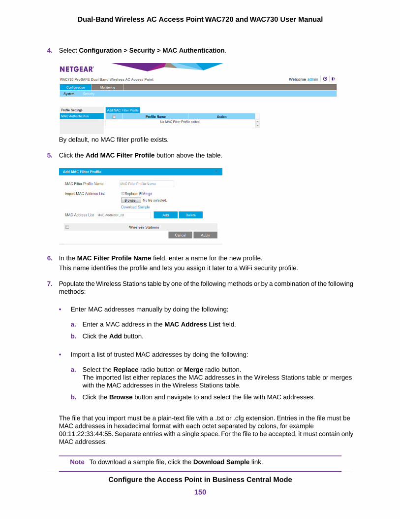
4. Select Configuration > Security > MAC Authentication.
By default, no MAC filter profile exists.
5. Click the Add MAC Filter Profile button above the table.
6. In the MAC Filter Profile Name field, enter a name for the new profile.
This name identifies the profile and lets you assign it later to a WiFi security profile.
7. Populate the Wireless Stations table by one of the following methods or by a combination of the followingmethods:
• Enter MAC addresses manually by doing the following:
a. Enter a MAC address in the MAC Address List field.
b. Click the Add button.
• Import a list of trusted MAC addresses by doing the following:
a. Select the Replace radio button or Merge radio button.The imported list either replaces the MAC addresses in the Wireless Stations table or mergeswith the MAC addresses in the Wireless Stations table.
b. Click the Browse button and navigate to and select the file with MAC addresses.
The file that you import must be a plain-text file with a .txt or .cfg extension. Entries in the file must beMAC addresses in hexadecimal format with each octet separated by colons, for example00:11:22:33:44:55. Separate entries with a single space. For the file to be accepted, it must contain onlyMAC addresses.
To download a sample file, click the Download Sample link.Note
Configure the Access Point in Business Central Mode
150
Dual-Band Wireless AC Access Point WAC720 and WAC730 User Manual
8. To fine-tune the Wireless Stations table and delete one or more MAC addresses from the WirelessStations table, select individual check boxes for the MAC addresses and click the Delete button.
9. Click the Apply button.
Your settings are saved. The Add MAC Filter Profile pop-up window closes.
For information about assigning the MAC address filter profile to a WiFi security profile, see Assign aMAC Address Filter Profile on an Access Point in Business Central Mode on page 151.
Assign a MAC Address Filter Profile on an Access Point inBusiness Central ModeFor you to enable MAC address authentication on a cloud-managed WiFi network, you must first set up aMAC address filter profile for local authentication (see Add a MAC Address Filter Profile on an Access Pointin Business Central Mode on page 149).
You enable MAC address authentication on a cloud-managed WiFi network by assigning a MAC addressfilter profile to the WiFi security profile for the WiFi network.
To assign a MAC address filter profile to a cloud-managed WiFi network on an access pointin Business Central mode:
1. Open a web browser from a computer that is connected to the same network as the access point or tothe access point directly through an Ethernet cable.
For more information, see Log In to the Access Point on page 16.
2. In the address bar, enter the IP address of the access point.
A login window opens.
3. Enter the user name and password.
The user name is admin. The default password is password. The user name and password arecase-sensitive.
Configure the Access Point in Business Central Mode
151
Dual-Band Wireless AC Access Point WAC720 and WAC730 User Manual
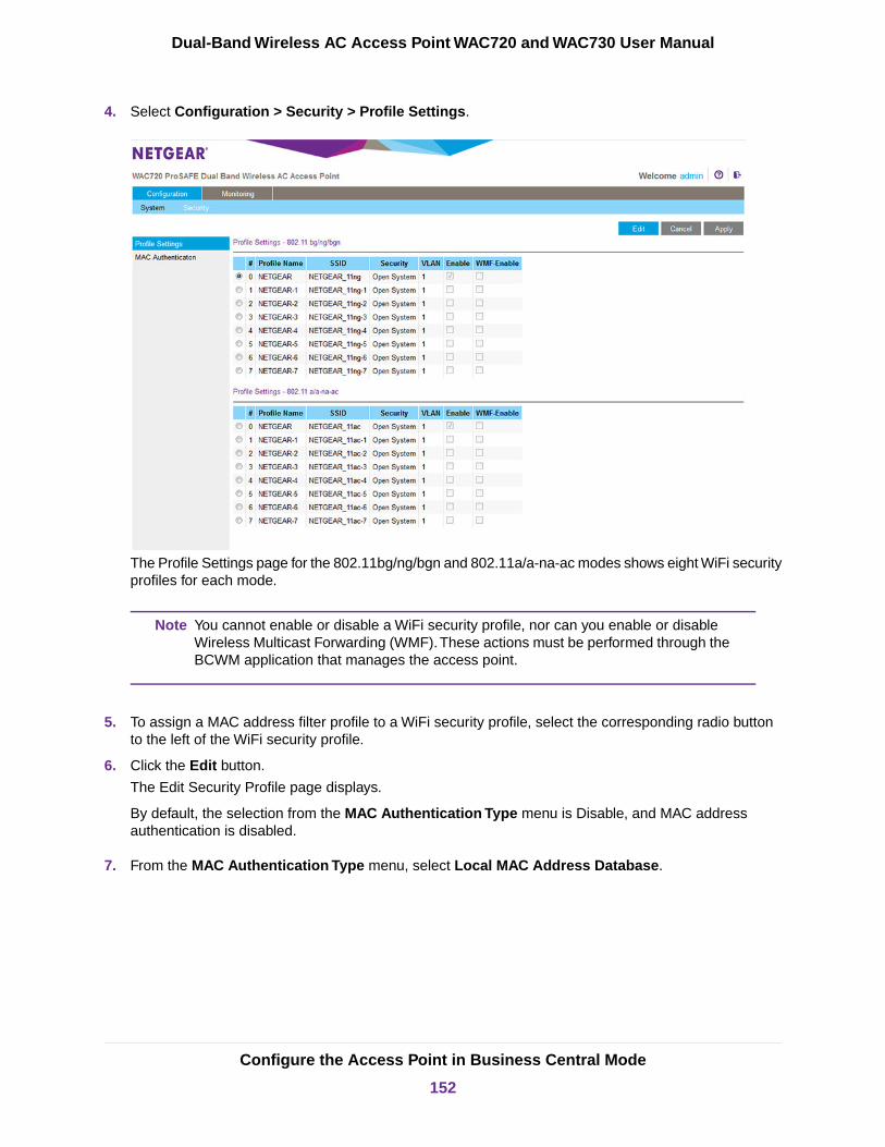
4. Select Configuration > Security > Profile Settings.
The Profile Settings page for the 802.11bg/ng/bgn and 802.11a/a-na-ac modes shows eight WiFi securityprofiles for each mode.
You cannot enable or disable a WiFi security profile, nor can you enable or disableWireless Multicast Forwarding (WMF).These actions must be performed through theBCWM application that manages the access point.
Note
5. To assign a MAC address filter profile to a WiFi security profile, select the corresponding radio buttonto the left of the WiFi security profile.
6. Click the Edit button.
The Edit Security Profile page displays.
By default, the selection from the MAC Authentication Type menu is Disable, and MAC addressauthentication is disabled.
7. From the MAC Authentication Type menu, select Local MAC Address Database.
Configure the Access Point in Business Central Mode
152
Dual-Band Wireless AC Access Point WAC720 and WAC730 User Manual
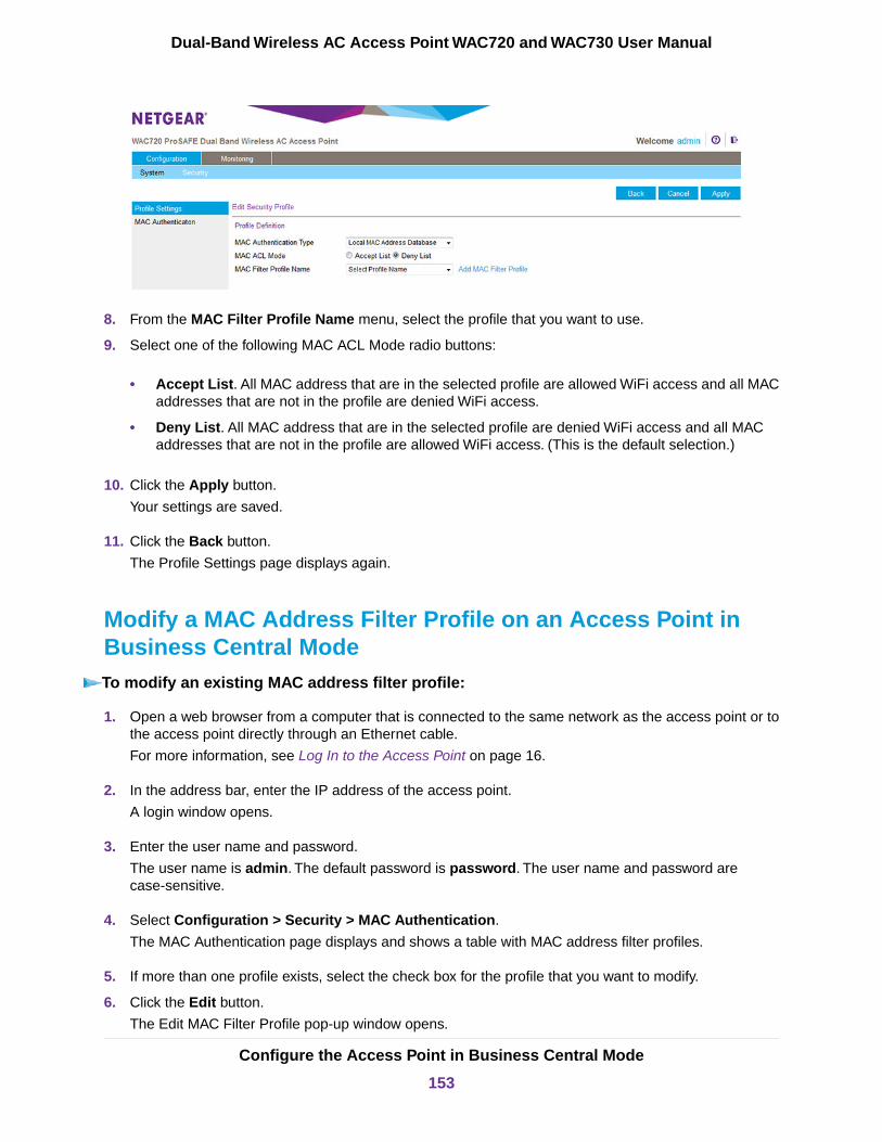
8. From the MAC Filter Profile Name menu, select the profile that you want to use.
9. Select one of the following MAC ACL Mode radio buttons:
• Accept List. All MAC address that are in the selected profile are allowed WiFi access and all MACaddresses that are not in the profile are denied WiFi access.
• Deny List. All MAC address that are in the selected profile are denied WiFi access and all MACaddresses that are not in the profile are allowed WiFi access. (This is the default selection.)
10. Click the Apply button.
Your settings are saved.
11. Click the Back button.
The Profile Settings page displays again.
Modify a MAC Address Filter Profile on an Access Point inBusiness Central ModeTo modify an existing MAC address filter profile:
1. Open a web browser from a computer that is connected to the same network as the access point or tothe access point directly through an Ethernet cable.
For more information, see Log In to the Access Point on page 16.
2. In the address bar, enter the IP address of the access point.
A login window opens.
3. Enter the user name and password.
The user name is admin. The default password is password. The user name and password arecase-sensitive.
4. Select Configuration > Security > MAC Authentication.
The MAC Authentication page displays and shows a table with MAC address filter profiles.
5. If more than one profile exists, select the check box for the profile that you want to modify.
6. Click the Edit button.
The Edit MAC Filter Profile pop-up window opens.
Configure the Access Point in Business Central Mode
153
Dual-Band Wireless AC Access Point WAC720 and WAC730 User Manual

7. Modify the MAC address filter profile.
For more information, see Add a MAC Address Filter Profile on an Access Point in Business CentralMode on page 149.
8. Click the Apply button.
Your settings are saved. The Add MAC Filter Profile pop-up window closes.
Delete a MAC Address Filter Profile on an Access Point inBusiness Central ModeTo delete an existing MAC address filter profile:
1. Open a web browser from a computer that is connected to the same network as the access point or tothe access point directly through an Ethernet cable.
For more information, see Log In to the Access Point on page 16.
2. In the address bar, enter the IP address of the access point.
A login window opens.
3. Enter the user name and password.
The user name is admin. The default password is password. The user name and password arecase-sensitive.
4. Select Configuration > Security > MAC Authentication.
The MAC Authentication page displays and shows a table with MAC address filter profiles.
5. Select the check box for the profile that you want to delete.
You can select more than one check box and delete several profiles.
6. Click the Delete Profile button.
The profile or profiles are deleted.
Monitor the Access Point in Business Central Mode
You can view the activity logs of an access point in Business Central mode, which can be useful if you aretroubleshooting a problem.
You can also view basic information about the access point.
Configure the Access Point in Business Central Mode
154
Dual-Band Wireless AC Access Point WAC720 and WAC730 User Manual
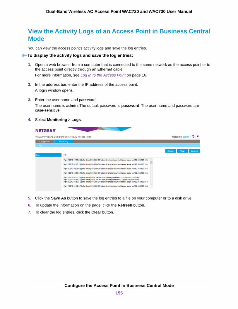
View the Activity Logs of an Access Point in Business CentralModeYou can view the access point’s activity logs and save the log entries.
To display the activity logs and save the log entries:
1. Open a web browser from a computer that is connected to the same network as the access point or tothe access point directly through an Ethernet cable.
For more information, see Log In to the Access Point on page 16.
2. In the address bar, enter the IP address of the access point.
A login window opens.
3. Enter the user name and password.
The user name is admin. The default password is password. The user name and password arecase-sensitive.
4. Select Monitoring > Logs.
5. Click the Save As button to save the log entries to a file on your computer or to a disk drive.
6. To update the information on the page, click the Refresh button.
7. To clear the log entries, click the Clear button.
Configure the Access Point in Business Central Mode
155
Dual-Band Wireless AC Access Point WAC720 and WAC730 User Manual
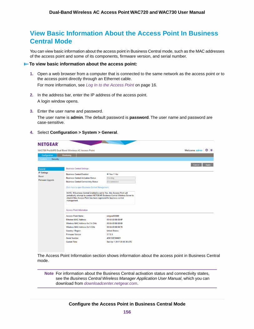
View Basic Information About the Access Point In BusinessCentral ModeYou can view basic information about the access point in Business Central mode, such as the MAC addressesof the access point and some of its components, firmware version, and serial number.
To view basic information about the access point:
1. Open a web browser from a computer that is connected to the same network as the access point or tothe access point directly through an Ethernet cable.
For more information, see Log In to the Access Point on page 16.
2. In the address bar, enter the IP address of the access point.
A login window opens.
3. Enter the user name and password.
The user name is admin. The default password is password. The user name and password arecase-sensitive.
4. Select Configuration > System > General.
The Access Point Information section shows information about the access point in Business Centralmode.
For information about the Business Central activation status and connectivity states,see the Business Central Wireless Manager Application User Manual, which you candownload from downloadcenter.netgear.com.
Note
Configure the Access Point in Business Central Mode
156
Dual-Band Wireless AC Access Point WAC720 and WAC730 User Manual

BSupplemental Information
This appendix provides factory default settings and technical specifications for the access point. The appendixincludes the following sections:
• Technical Specifications• Factory Default Settings
157

Technical Specifications
Table 4.Technical specifications
DescriptionFeature
802.11bg/ng/bgn WiFi specifications
1, 2, 5.5, and 11 Mbps, and auto-rate capable802.11b data rates
1, 2, 5.5, 6, 9, 11, 12, 18, 24, 36, 48, 54 Mbps, and auto-rate capable802.11bg data rates
Data rates for a 20 MHz channel width and an automatic guard interval:
0 / 7.2 Mbps, 1 / 14.4 Mbps, 2 / 21.7 Mbps, 3 / 28.9 Mbps, 4 / 43.3 Mbps, 5 / 57.8 Mbps, 6/ 65 Mbps, 7 / 72.2 Mbps, 8 / 14.44 Mbps, 9 / 28.88 Mbps, 10 / 43.33 Mbps, 11 / 57.77 Mbps,12 / 86.66 Mbps, 13 / 115.56 Mbps, 14 / 130 Mbps, 15 / 144.44 Mbps, 16 / 21.7 Mbps, 17 /43.3 Mbps, 18 / 65 Mbps, 19 / 86.7 Mbps, 20 / 130.7 Mbps, 21 / 173.3 Mbps, 22 / 195 Mbps,23 / 216.7 Mbps, and auto-rate capable
802.11bgn MCS indexand data rates
Data rates for a 20 MHz channel width and a long guard interval (800 ms):
0 / 6.5 Mbps, 1 / 13 Mbps, 2 / 19.5 Mbps, 3 / 26 Mbps, 4 / 39 Mbps, 5 / 52 Mbps, 6 / 58.5Mbps, 7 / 65 Mbps, 8 / 13 Mbps, 9 / 26 Mbps, 10 / 39 Mbps, 11 / 52 Mbps, 12 / 78 Mbps, 13/ 104 Mbps, 14 / 117 Mbps, 15 / 130 Mbps, 16 / 19.5 Mbps, 17 / 39 Mbps, 18 / 58.5 Mbps,19 / 78 Mbps, 20 / 117 Mbps, 21 / 156 Mbps, 22 / 175.5 Mbps, 23 / 195 Mbps, and auto-ratecapable
Data rates for a 40 MHz channel width and an automatic guard interval:
0 / 15 Mbps, 1 / 30 Mbps, 2 / 45 Mbps, 3 / 60 Mbps, 4 / 90 Mbps, 5 / 120 Mbps, 6 / 135 Mbps,7 / 150 Mbps, 8 / 30 Mbps, 9 / 60 Mbps, 10 / 90 Mbps, 11 / 120 Mbps, 12 / 180 Mbps, 13 /240 Mbps, 14 / 270 Mbps, 15 / 300 Mbps, 16 / 45 Mbps, 17 / 90 Mbps, 18 / 135 Mbps, 19 /180 Mbps, 20 / 270 Mbps, 21 / 360 Mbps, 22 / 405 Mbps, 23 / 450 Mbps, and auto-ratecapable
Data rates for a 40 MHz channel width and a long guard interval (800 ms):
0 / 13.5 Mbps, 1 / 27 Mbps, 2 / 40.5 Mbps, 3 / 54 Mbps, 4 / 81 Mbps, 5 / 108 Mbps, 6 / 121.5Mbps, 7 / 135 Mbps, 8 / 27 Mbps, 9 / 54 Mbps, 10 / 81 Mbps, 11 / 108 Mbps, 12 / 162 Mbps,13 / 216 Mbps, 14 / 243 Mbps, 15 / 270 Mbps, 16 / 40.5 Mbps, 17 / 81 Mbps, 18 / 121.5Mbps, 19 / 162 Mbps, 20 / 243 Mbps, 21 / 324 Mbps, 22 / 364.5 Mbps, 23 / 405 Mbps, andauto-rate capable
• 2.412–2.462 GHz (US)
• 2.457–2.462 GHz (Spain)
• 2.410–2.484 GHz (Japan 11b)
• 2.410–2.472 GHz (Japan 11ng)
• 2.457–2.472 GHz (France)
• 2.412–2.472 GHz (Europe ETSI)
• 2.412–2.472 GHz (China)
802.11bg/ng/bgnoperating frequencies
Supplemental Information
158
Dual-Band Wireless AC Access Point WAC720 and WAC730 User Manual

Table 4.Technical specifications (Continued)
DescriptionFeature
• WPA-PSK & WPA2-PSK
• AES
• TKIP
802.11 bg/ng/bgnencryption
802.11a/a-na-ac WiFi specifications
6, 9, 12, 18, 24, 36, 48, 54 Mbps, and auto-rate capable802.11a data rates
Data rates for a 20 MHz channel width and an automatic guard interval:
0 / 7.2 Mbps, 1 / 14.4 Mbps, 2 / 21.7 Mbps, 3 / 28.9 Mbps, 4 / 43.3 Mbps, 5 / 57.8 Mbps, 6/ 65 Mbps, 7 / 72.2 Mbps, 8 / 14.44 Mbps, 9 / 28.88 Mbps, 10 / 43.33 Mbps, 11 / 57.77 Mbps,12 / 86.66 Mbps, 13 / 115.56 Mbps, 14 / 130 Mbps, 15 / 144.44 Mbps, 16 / 21.7 Mbps, 17 /43.3 Mbps, 18 / 65 Mbps, 19 / 86.7 Mbps, 20 / 130.7 Mbps, 21 / 173.3 Mbps, 22 / 195 Mbps,23 / 216.7 Mbps, and auto-rate capable
802.11a/a-na-ac datarates
Data rates for a 20 MHz channel width and a long guard interval (800 ms):
0 / 6.5 Mbps, 1 / 13 Mbps, 2 / 19.5 Mbps, 3 / 26 Mbps, 4 / 39 Mbps, 5 / 52 Mbps, 6 / 58.5Mbps, 7 / 65 Mbps, 8 / 13 Mbps, 9 / 26 Mbps, 10 / 39 Mbps, 11 / 52 Mbps, 12 / 78 Mbps, 13/ 104 Mbps, 14 / 117 Mbps, 15 / 130 Mbps, 16 / 19.5 Mbps, 17 / 39 Mbps, 18 / 58.5 Mbps,19 / 78 Mbps, 20 / 117 Mbps, 21 / 156 Mbps, 22 / 175.5 Mbps, 23 / 195 Mbps, and auto-ratecapable
Data rates for a 40 MHz channel width and an automatic guard interval:
0 / 15 Mbps, 1 / 30 Mbps, 2 / 45 Mbps, 3 / 60 Mbps, 4 / 90 Mbps, 5 / 120 Mbps, 6 / 135 Mbps,7 / 150 Mbps, 8 / 30 Mbps, 9 / 60 Mbps, 10 / 90 Mbps, 11 / 120 Mbps, 12 / 180 Mbps, 13 /240 Mbps, 14 / 270 Mbps, 15 / 300 Mbps, 16 / 45 Mbps, 17 / 90 Mbps, 18 / 135 Mbps, 19 /180 Mbps, 20 / 270 Mbps, 21 / 360 Mbps, 22 / 405 Mbps, 23 / 450 Mbps, and auto-ratecapable
Data rates for a 40 MHz channel width and a long guard interval (800 ms):
0 / 13.5 Mbps, 1 / 27 Mbps, 2 / 40.5 Mbps, 3 / 54 Mbps, 4 / 81 Mbps, 5 / 108 Mbps, 6 / 121.5Mbps, 7 / 135 Mbps, 8 / 27 Mbps, 9 / 54 Mbps, 10 / 81 Mbps, 11 / 108 Mbps, 12 / 162 Mbps,13 / 216 Mbps, 14 / 243 Mbps, 15 / 270 Mbps, 16 / 40.5 Mbps, 17 / 81 Mbps, 18 / 121.5Mbps, 19 / 162 Mbps, 20 / 243 Mbps, 21 / 324 Mbps, 22 / 364.5 Mbps, 23 / 405 Mbps, andauto-rate capable
Data rates for an 80 MHz channel width and an automatic guard interval:
0 / 97.5 Mbps, 1 / 195 Mbps, 2 / 292.5 Mbps, 3 / 390 Mbps, 4 / 585 Mbps, 5 / 780 Mbps, 6/ 877.5 Mbps, 7 / 975 Mbps, 8 / 1170 Mbps, 9 / 1300 Mbps, and auto-rate capable
Data rates for an 80 MHz channel width and a long guard interval (800 ms):
0 / 87.9 Mbps, 1 / 175.5 Mbps, 2 / 263.4 Mbps, 3 / 351 Mbps, 4 / 526.5 Mbps, 5 / 702 Mbps,6 / 789.9 Mbps, 7 / 877.5 Mbps, 8 / 1053 Mbps, 9 / 1170 Mbps, and auto-rate capable
Supplemental Information
159
Dual-Band Wireless AC Access Point WAC720 and WAC730 User Manual
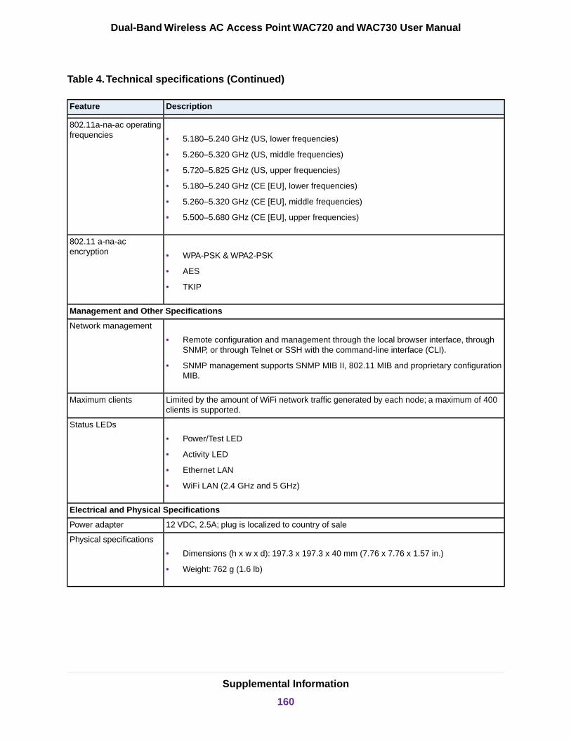
Table 4.Technical specifications (Continued)
DescriptionFeature
• 5.180–5.240 GHz (US, lower frequencies)
• 5.260–5.320 GHz (US, middle frequencies)
• 5.720–5.825 GHz (US, upper frequencies)
• 5.180–5.240 GHz (CE [EU], lower frequencies)
• 5.260–5.320 GHz (CE [EU], middle frequencies)
• 5.500–5.680 GHz (CE [EU], upper frequencies)
802.11a-na-ac operatingfrequencies
• WPA-PSK & WPA2-PSK
• AES
• TKIP
802.11 a-na-acencryption
Management and Other Specifications
• Remote configuration and management through the local browser interface, throughSNMP, or through Telnet or SSH with the command-line interface (CLI).
• SNMP management supports SNMP MIB II, 802.11 MIB and proprietary configurationMIB.
Network management
Limited by the amount of WiFi network traffic generated by each node; a maximum of 400clients is supported.
Maximum clients
• Power/Test LED
• Activity LED
• Ethernet LAN
• WiFi LAN (2.4 GHz and 5 GHz)
Status LEDs
Electrical and Physical Specifications
12 VDC, 2.5A; plug is localized to country of salePower adapter
• Dimensions (h x w x d): 197.3 x 197.3 x 40 mm (7.76 x 7.76 x 1.57 in.)
• Weight: 762 g (1.6 lb)
Physical specifications
Supplemental Information
160
Dual-Band Wireless AC Access Point WAC720 and WAC730 User Manual
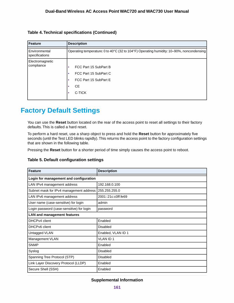
Table 4.Technical specifications (Continued)
DescriptionFeature
Operating temperature: 0 to 40°C (32 to 104°F) Operating humidity: 10–90%, noncondensingEnvironmentalspecifications
• FCC Part 15 SubPart B
• FCC Part 15 SubPart C
• FCC Part 15 SubPart E
• CE
• C-TICK
Electromagneticcompliance
Factory Default Settings
You can use the Reset button located on the rear of the access point to reset all settings to their factorydefaults. This is called a hard reset.
To perform a hard reset, use a sharp object to press and hold the Reset button for approximately fiveseconds (until the Test LED blinks rapidly).This returns the access point to the factory configuration settingsthat are shown in the following table.
Pressing the Reset button for a shorter period of time simply causes the access point to reboot.
Table 5. Default configuration settings
DescriptionFeature
Login for management and configuration
192.168.0.100LAN IPv4 management address
255.255.255.0Subnet mask for IPv4 management address
2001::21c:c0ff:fe69LAN IPv6 management address
adminUser name (case-sensitive) for login
passwordLogin password (case-sensitive) for login
LAN and management features
EnabledDHCPv4 client
DisabledDHCPv6 client
Enabled, VLAN ID 1Untagged VLAN
VLAN ID 1Management VLAN
EnabledSNMP
DisabledSyslog
DisabledSpanning Tree Protocol (STP)
EnabledLink Layer Discovery Protocol (LLDP)
EnabledSecure Shell (SSH)
Supplemental Information
161
Dual-Band Wireless AC Access Point WAC720 and WAC730 User Manual

Table 5. Default configuration settings (Continued)
DescriptionFeature
DisabledTelnet
USA-PacificTime zone
EnabledNTP client
DisabledCustom NTP server
10/100/1000Port speed
See bottom labelEthernet MAC address
Radio and WiFi settings
Access point, infrastructure modeOperating mode
netgearxxxxxx, where xxxxxx are the last 6 digits of the WiFi accesspoint MAC address
WiFi access point name
Varies by regionCountry and region
2.4 GHz radio enabled
5 GHz radio enabled
WiFi communication
11bg/ng/bgn
11a/a-na-ac
WiFi modes
NETGEAR_11ng
NETGEAR_11ac
WiFi network names (SSIDs)
EnabledBroadcast network names (SSIDs)
11ng: Auto
11ac: Auto
Radio frequency channels
Best
Maximum WiFi signal rate derived from IEEEStandard 802.11 specifications. Actual throughputwill vary. Network conditions and environmentalfactors, including volume of network traffic, buildingmaterials and construction, and network overhead,lower actual data throughput rate.
Note
MCS index/data rate (transmission speed)
11ng: 20 MHz
11ac: Dynamic 20/40 MHz
Channel width
AutoGuard interval
FullOutput power
DisabledWiFi on/off (radio scheduling)
2347RTS threshold
2346Fragmentation length
100Beacon interval
Supplemental Information
162
Dual-Band Wireless AC Access Point WAC720 and WAC730 User Manual

Table 5. Default configuration settings (Continued)
DescriptionFeature
65535Aggregation length
EnabledA-MPDU
DisabledRIFS transmission
3DTIM interval
AutoPreamble type
InternalAntenna
Enabled802.11d
400Maximum WiFi clients
EnabledWi-Fi Multimedia (WMM)
EnabledWMM powersave
See Configure and Manage Quality of Service Policies on page 112.AP EDCA parameters (QoS settings)
Station EDCA parameters (QoS settings)
NoneQoS policies
DisabledWiFi bridging
Default WiFi profile and profile security
NETGEARProfile name
EnabledProfile state
NETGEAR_11ng
NETGEAR_11ac
WiFi network names (SSIDs)
EnabledBroadcast WiFi network names (SSIDs)
Open system (no authentication)Network authentication
NoneData encryption
DisabledWiFi client security separation
1VLAN ID
WiFi security features
DisabledRogue AP detection
ModerateRogue AP detection policy
DisabledMAC authentication
NoneRADIUS servers
1812RADIUS authentication port number
sharedsecretRADIUS shared secret
1813RADIUS accounting port number
3600 secondsRADIUS reauthentication time
1800 secondsRADIUS update of the global key
Supplemental Information
163
Dual-Band Wireless AC Access Point WAC720 and WAC730 User Manual


