USER MANUAL NetGuardian G5 Expansion March 5, 2012 D-OC-UM10C.02100 Firmware Version 5.0B Visit our website at www.dpstele.com for the latest PDF manual and FAQs. (Discretes, Relays, and Analogs)
Transcript
USER MANUAL
NetGuardian G5 Expansion
March 5, 2012 D-OC-UM10C.02100 Firmware Version 5.0B
Visit our website at www.dpstele.com for the latest PDF manual and FAQs.
This document contains proprietary information which is protected by copyright. All rights are reserved. No part of thisdocument may be photocopied without prior written consent of DPS Telecom.
All software and manuals are copyrighted by DPS Telecom. Said software and manuals may not be reproduced, copied,transmitted or used to make a derivative work, by either mechanical, electronic or any other means in whole or in part, withoutprior written consent from DPS Telecom, except as required by United States copyright laws.
The material in this manual is for information purposes and is subject to change without notice. DPS Telecom shall not beliable for errors contained herein or consequential damages in connection with the furnishing, performance, or use of thismanual.
Notice
Revision History
March 5, 2012
December 2, 2010
May 10, 2010
April 16, 2010
Updated shipping list
Added FCC compliance notice for Class A device
Added pinout for build without control relays.
D-OC-UM104.16100 released.
ContentsVisit our website at www.dpstelecom.com for the latest PDF manual and FAQs
NetGuardian Expansion Overview1 1
Summary of Features1.1 1
Introduction1.2 1
Installation2 2
Shipping List2.1 2
Optional Accessories2.2 3
Specifications2.3 4
Hardware Installation2.4 5
Site Preparation2.4.1 5
Installation Steps Overview2.4.2 5
Mounting Instructions2.4.3 5
Power and Ground Connection2.4.4 6
Communication Lines2.4.5 8
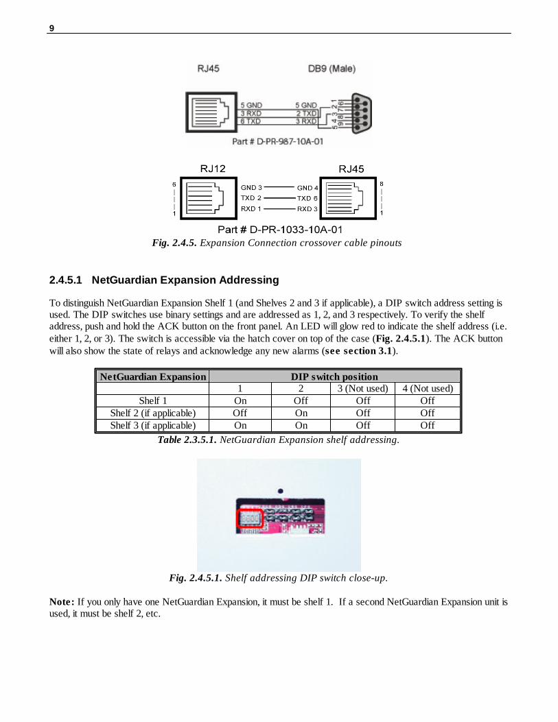
2.4.5.1 NetGuardian Expansion Addressing 9
Alarm and Control Relay Connections2.4.6 10
2.4.6.1 Alarm, Control, and Analog Connectors (832 DX G5) 11
2.4.6.2 Alarm, Control, and Analog Connectors (864 DX G5) 13
2.4.6.3 Changing Jumper Options 16
2.4.6.4 Analog Dipswitches 18
Power-up2.4.7 18
NGEdit Configuration2.4.8 19
Web Browser Configuration2.5 21
Logon2.5.1 21
Configuring the Expansion Unit2.5.2 22
Setting Up An Expansion Alarm2.5.3 24
Setting Up a Relay2.5.4 26
Setting Up an Analog2.5.5 28
Operation3 29
Front Panel Functions3.1 29
Upgrading Firmware3.2 30
Display Mapping3.3 31
Technical Support4 33
End User License Agreement5 34
1
NetGuardian Expansion Overview1
Summary of Features1.1
Low cost method of expansion to existing NetGuardian 832A or 864A G5 units (supported by NetGuardian G2,G4, G5 and others)
Gives additional capacity over existing communications lines
Helps conserve T/MonXM or IAM ports by reporting more alarms to the same address
32 or 64 ground activated discrete alarms per expansion
8 additional relay contact closures per expansion
8 additional analog channels per expansion *
RS232 ports for easy daisy chaining between units
LED indications of alarms and communications status
Easy setup
DPS has kept the operation and interfaces of the DX G5 model very similar to previous DX models. You will findthe new DX G5 very interchangeable with existing DX equipment. Note: The pinout may vary depending on yourDX G5 model, so you may need to adjust connectors to interchange with existing DX equipment.
* When used in conjunction with the NetGuardian 832A or 864A G5 as the base unit. Not compatible as anexpansion to the NetGuardian 832A G2 or G4.
Introduction1.2
The NetGuardian Expansion box is a low cost, self contained device that provides the NetGuardian 832A with anadditional 32 or 64 ground activated discrete alarms per unit. With the capacity of adding up to 3 NetGuardianExpansions, at 32 or 64 alarms points per unit, an additional 96 or 192 discrete alarms to the base NetGuardian832A or 864A can be provided.
To make expansion a simpler and less expensive task, each unit is equipped with dual RS232 ports so thatadditional Expansions can be daisy chained to one another. In this way, currently deployed NetGuardian 832Ascan be easily expanded.
x2Two Large Power Connector Plugs for Main Power2-820-00862-02
3
Optional Accessories2.2
8' RJ45 to RJ45 connection cableD-PR-1028-10C-08 (1 per unit)(for connection to NetGuardian 832A G5)
Note: Please refer to Page 8 for pinout information
4
Specifications2.3
Physical Dimensions: 1.720" H x 17.026" W x 9.636" D (NetGuardian 864 DX)1.720" H x 17.026" W x 8.136" D (NetGuardian 832 DX)
Weight: 2.3 lb Mounting: 19" or 23" rack with supplied ears
Discrete Alarms: 32 per NetGuardian 832 DX G564 per NetGuardian 864 DX G5
Control Relays: 8 (optional)
Analogs: 8 (optional) *
Operating temperature: 41º – 95ºF (5º – 35ºC)
Power InputVoltage Options Include: –48 VDC (-40 to -70 VDC)
(Optional) -24 VDC (-18 to -36 VDC)(Optional) Wide Range -24/-48 VDC (-18 to -58 VDC)
Fuse: 3/4 amp GMTCurrent Draw: 250mA
Interfaces: 1 - RJ45 connector for RS232 1 - RJ12 connector for RS232
2 - 50 Pin connectors for discrete alarms, controls, and analogs 1-61 - 4-pin connector for analogs 7-8
Protocol: DCPX
MTBF: 60 years
Windows Compatibility: Windows 95, 98, NT, ME, XP, 2000, Vista, 7 32/64 bit
* When used in conjunction with the NetGuardian 832A or 864A G5 as the base unit. Not compatible as anexpansion to the NetGuardian 832A G2 or G4.
FCC Compliance:
This equipment has been tested and found to comply with the limits for a Class A digital device, pursuant to part15 of the FCC Rules. These limits are designed to provide reasonable protection against harmful interferencewhen the equipment is operated in a commercial environment. This equipment generates, uses, and can radiateradio frequency energy and, if not installed and used in accordance with the instruction manual, may causeharmful interference to radio communications. Operation of this equipment in a residential area is likely to causeharmful interference in which case the user will be required to correct the interference at his own expense.
5
Hardware Installation2.4
2.4.1 Site Preparation
Tools needed:
Phillips screwdriver
Small standard No. 2 screwdriver
Wire strippers/cutters
! Precaution
* Pull fuses on source of -48VDC before connecting power. * Always observe electrostatic discharge (ESD) precautions.
2.4.2 Installation Steps Overview
Mount hardware: Mount NetGuardian Expansion in the rack.
Connect alarms leads.
Connect power.
Provision NetGuardian 832A / 864A G5 for NetGuardian Expansion
Review NetGuardian Expansion status LEDs.
2.4.3 Mounting Instructions
The NetGuardian Expansion can be mounted in a 19" or a "23" rack by using different rack ears for each size. Attach the appropriate size ears for your rack in the flush-mount locations shown in the figures below.
Fig. 2.4.3. The NetGuardian Expansion can be flush (top) or rear-mounted, as shown above.
Note: Rack ears can be flipped 180° for other mounting options not shown.
6
2.4.4 Power and Ground Connection
Fig. 2.4.4. Power connectors and fuses
The NetGuardian Expansiom has two screw terminal barrier plug power connectors, located on the left side of theback panel. (See Figure 2.4.4.)
Before you connect a power supply to the NetGuardian Expansion, test the voltage of your powersupply:
Connect the black common lead of a voltmeter to the ground terminal of the battery, and connect the redlead of the voltmeter to the battery's –48 VDC terminal. The voltmeter should read between –43 and –53 VDC. If the reading is outside this range, test the power supply.
To connect the NetGuardian Expansion to a power supply, follow these steps:
1. Remove Fuse A and Fuse B from the back panel of the NetGuardian Expansion. Do not reinsert thefuses until all connections to the unit have been made.
2. Remove the power connector plug from Power Connector A. Note that the plug can be inserted into thepower connector only one way - this ensures that the barrier plug can only be reinserted with the correctpolarity. Note that the –48V terminal is on the left and the RTN terminal is on the right.
3. Use the grounding lug to properly ground the unit.
4. Insert a battery ground into the power connector plug's right terminal and tighten the screw; theninsert a –48 VDC line to the plug's left terminal and tighten its screw.
5. Push the power connector plug firmly back into the power connector. If the power feed is connectedcorrectly, the LED by the connector will light GREEN. The LED by the power connector will be off ifthe power feed is reversed.
6. Repeat Steps 2–5 for Power Connector B.
7. Reinsert Fuse A and Fuse B to power the NetGuardian Expansion. The front panel LEDs will flash REDand GREEN.
To connect the NetGuardian to a power supply using a WAGO connector, follow these steps:
1. Remove the 2 fuses (A& B) from the back panel of the NetGuardian. Do not reinsert the fuses until allconnections to the unit have been made.
2. Remove the WAGO power connector. Note that the plug can be inserted into thepower connector only one way - this ensures that the barrier plug can only be reinserted with thecorrect polarity. Note that the –48V terminal is on Slots 1 and 3 and the GND terminal is on Slots 2 and 4.
7
3. Use the grounding lug to properly ground the unit.
4. Insert a battery ground into the power connector plug's slots 2 and 4 by pushing down on top of theappropriate slot of the WAGO connector with a screwdriver and inserting the wire into the slot, then releasing thescrewdriver. Insert a –48 VDC line to the plug's slots 1 and 3 using the same method as before.
Inserting a -48 VDC Line into Slot 1 of WAGO
Connector
5. Push the power connector plug firmly back into the power connector. If the power feed is connected correctly,the LED by the connector will light GREEN. If the polarity of the power feed is reversed, the LED will notilluminate.
6. Reinsert the fuses to power the NetGuardian. The front panel LEDs will flash RED and GREEN.
8
2.4.5 Communication Lines
1. Connect one end of the RJ45-RJ45 cable to reach through port number 7 (of the 8) located on the NetGuardianG5 back panel.Note: For NetMediator G5 products (TNT or T2S) use expansion port.2. Connect the other end of the RJ45-RJ45 cable to the “DX In” port of the NetGuardian Expansion (See Figure2.3.5 below). Note: If interfacing to the legacy NetGuardian G2 model, then use the supplied DB9-to-RJ45 cable instead.
If additional NetGuardian Expansions are to be installed:
3. Connect one end of another RJ12-RJ45 cable to the “DX Out” port in the first NetGuardian Expansion.4. Connect the other end of that RJ12-RJ45 cable to the “DX In” port of the second NetGuardian Expansion.5. To connect a third NetGuardian Expansion, repeat steps 3 and 4.Note: The “DX IN” and “DX OUT” ports as well as the NetGuardian’s Data Ports are DCE type ports.
Fig. 2.3.5. NetGuardian Expansion with communications line
To distinguish NetGuardian Expansion Shelf 1 (and Shelves 2 and 3 if applicable), a DIP switch address setting isused. The DIP switches use binary settings and are addressed as 1, 2, and 3 respectively. To verify the shelfaddress, push and hold the ACK button on the front panel. An LED will glow red to indicate the shelf address (i.e.either 1, 2, or 3). The switch is accessible via the hatch cover on top of the case (Fig. 2.4.5.1). The ACK buttonwill also show the state of relays and acknowledge any new alarms (see section 3.1).
Note: If you only have one NetGuardian Expansion, it must be shelf 1. If a second NetGuardian Expansion unit isused, it must be shelf 2, etc.
10
2.4.6 Alarm and Control Relay Connections
Fig. 2.4.6 Alarm and control relay connectors
The NetGuardian 832/864 DX's discrete alarm inputs and control relay outputs are connected through the two 50-pinconnectors, located on the back panel.
Discrete alarm points connected to the NetGuardian 864 Expansion variant are essentially single-lead signalsreferenced to ground. The B-side of each alarm point is internally wired to ground, so either a single wire bringinga contact to ground or a dry closure with the second lead connected to the B-side will be sensed as an alarmsignal.
For the NetGuardian 832 Expansion variant, there are 2 leads per alarm signal, and the pinout is exactly thesame as a standard NetGuardian 832A.
11
2.4.6.1 Alarm, Control, and Analog Connectors (832 DX G5)
Discretes 1–25
RTN ALM RTN ALM
ALM 1 1 26 ALM 13 13 38
ALM 2 2 27 ALM 14 14 39
ALM 3 3 28 ALM 15 15 40
ALM 4 4 29 ALM 16 16 41
ALM 5 5 30 ALM 17 17 42
ALM 6 6 31 ALM 18 18 43
ALM 7 7 32 ALM 19 19 44
ALM 8 8 33 ALM 20 20 45
ALM 9 9 34 ALM 21 21 46
ALM 10 10 35 ALM 22 22 47
ALM 11 11 36 ALM 23 23 48
ALM 12 12 37 ALM 24 24 49
GND 25 50
Discretes 25–32
RTN ALM
ALM 25 1 26
ALM 26 2 27
ALM 27 3 28
ALM 28 4 29
ALM 29 5 30
ALM 30 6 31
ALM 31 7 32
ALM 32 8 33
Control Relays 1–8
NO/NC CO
CTRL 1 9 34
CTRL 2 10 35
CTRL 3 11 36
CTRL 4 12 37
CTRL 5 13 38
CTRL 6 14 39
CTRL 7 15 40
CTRL 8 16 41
FUSE 17 42
Analogs 1–6
ADC + –
ADC 1 19 44
ADC 2 20 45
ADC 3 21 46
ADC 4** 22 47
ADC 5** 23 48
ADC 6** 24 49
GND 25 50
Analogs 7–8
ADC – +
7 7– 7+
8 8– 8+
Analogs 7 –8
ANA 7 – ANA 8 +
ANA 7 + ANA 8 –
Alarm and control relay connector pinout for the NetGuardian 832A DX G5
Note that the NetGuardian's control relays can be set for either Normally Open or Normally Closed operation. Byfactory default, all control relays are set to Normally Open. You can reset all relays for Normally Closed operationat the hardware level by resetting a jumper on the NetGuardian circuit board. You can also configure the controlrelays individually, using either the Web interface or the NGEditG5 software utility.
For instructions on resetting control relays for Normally Closed operation, see Section 6.12, "Jumper Options."
ADC** channels 4, 5, and 6 may be unavailable for external use. These analog channels aresometimes configured in hardware for monitoring A and B power feeds, and internal temperature. Fordetails regarding your unit's hardware, please reference the product description appendix.
Pinout Diagram for Discretes 24-32, Analogs 1-6,and Relays 1-8 connector on the NetGuardian 832
DX G5.
13
2.4.6.2 Alarm, Control, and Analog Connectors (864 DX G5)
Discretes 1–48
ALM PIN ALM PIN
1 26 26 13
2 1 27 39
3 27 28 14
4 2 29 40
5 28 30 15
6 3 31 41
7 29 32 16
8 4 33 42
9 30 34 17
10 5 35 43
11 31 36 18
12 6 37 44
13 32 38 19
14 7 39 45
15 33 40 20
16 8 41 46
17 34 42 21
18 9 43 47
19 35 44 22
20 10 45 48
21 36 46 23
22 11 47 49
23 37 48 24
24 12 GND 25
25 38 GND/RTN* 50
Discretes 49-64, Relays 1-8, Analogs 1-6
ALM PIN Relays 1-8
49 26 RLY 1 9 34
50 1 RLY 2 10 35
51 27 RLY 3 11 36
52 2 RLY 4 12 37
53 28 RLY 5 13 38
54 3 RLY 6 14 39
55 29 RLY 7 15 40
56 4 RLY 8 16 41
57 30 FUSE 17 42
58 5 ADC + -
59 31 ADC 1 19 44
60 6 ADC 2 20 45
61 32 ADC 3 21 46
62 7 ADC 4** 22 47
63 33 ADC 5** 23 48
64 8 ADC 6** 24 49
GND 25
GND/RTN* 50
Analogs 7-8
ADC + -
7 B A
8 B A
Alarm and relay connection pinouts for NetGuardian 864 DX G5
RTN* is the alarm return pin. Alarms on standard units are dry closure or ground closure. Most units willhave RTN internally tied to GND. However, special hardware assemblies may have RTN isolated fromGND. For details regarding your unit's hardware, please reference the product description appendix.
ADC** channels 4, 5, and 6 may be unavailable for external use. These analog channels aresometimes configured in hardware for monitoring A and B power feeds, and internal temperature. Fordetails regarding your unit's hardware, please reference the product description appendix.
14
Pinout Diagram for Discretes 1-48 Connector on theNetGuardian 864A DX
Pinout Diagram for Analogs 1-6/Discretes 49-64/Relays 1-8 Connector
RTN* is the alarm return pin. Standard configurations have this pin tied to GND. While it is possible tochange this configuration to utilize different types of alarms (i.e. TTL, Open Collector, Battery Closure),the hardware must be ordered in that configuration. It is NOT field-adjustable.
15
Pinout Diagram for Analogs 1-6/Discretes 49-64. This pinout only applies to the NetGuardian 864 DX G5 without relays. See note below.
Note: Figure 6.6.5.2 is a special pinout for a particular build of the NetGuardian 864 DX G5 withoutcontrol relays. It only applies to the following part number: D-PK-DX864-12007.00001
16
2.4.6.3 Changing Jumper Options
Fig. 2.4.6.2.1 Adjustable jumpers on the NetGuardian circuit board
The following options are adjusted by resetting jumpers on the NetGuardian DX's circuit board:Control relays can be switched from normally open (N/O) to normally closed (N/C)
To simply configure the jumpers, use the hatch panel access on the top of the NetGuardian DX chassis. This allowsfor easy access and configuration of jumpers without having to open the entire case. Remove top screw on hatchpanel and rotate hatch cover until you can easily reach the jumpers. Figure 2.4.6.2.1 shows the circuit board andthe location of the adjustable jumpers.
Hatch Panel Access on Top of NetGuardian DX G5 Chassis
WARNING: Always observe anti-static precautions whenever opening the unit.
17
Fig. 2.4.6.2.2. Jumper settings for control relays
For control relay jumpers, the open position corresponds to normally open operation, and the closed positioncorresponds to normally closed operation. See Figure 2.4.6.2.2.
Note: Default settings may be different if you ordered a special configuration NetGuardian.
18
2.4.6.4 Analog Dipswitches
The analogs are controlled by the dipswitches accessible via the top sliding panel. For milliamp sensor operation(current loop), turn the dipswitch on by placing it in the up (ON) position. For voltage operation, place thedipswitch in the down (OFF) position.
You can access the analog dipswitches via the sliding hatch panel on top of the unit
WARNING: Do not put the dipswitches in the upward, ON position (current loop mode) unless youare sure of the analog setting. Having the dipswitch on puts a 250 ohm resistor across the inputlines. Any voltage beyond 5V or 20 mA will damage components.
2.4.7 Power-up
Now that all alarm and communications wiring is complete, power up the unit by installing Fuse A and Fuse B inthe back panel.
19
2.4.8 NGEdit Configuration
NGEditG5 is the DPS-recommended way for configuring points on the NetGuardian DX. You can refer to theNGEditG5 Help File or the NGEditG5 User Manual for full instructions. The following is to show you the screensyou would use to configure the NetGuardian DX.
Click the Ports tab to access the Options drop-down menu
20
Configure Your Selected DX with the Alarms Tab.
When you click on the Expansion tab in the Alarms screen, enter the appropriate event in the Description field.
Configure the expansion unit's analogs in the Analogs tab.
Click on the Analogs tab to enter in the analog descriptions, threshold settings, and notification choices for theexpansion units.
21
Web Browser Configuration2.5
The base NetGuardian 832A or 864A G5 offers Web Browser configuration for easy and convenient setup ofthe discrete alarms. The NetGuardian 864 DX supports Internet Explorer versions 6.0 and up and NetscapeNavigator versions 4.7 and up.
2.5.1 Logon
1. After connecting to the NetGuardian's IP address, enter your password and click Submit (factory defaultpassword is "dpstelecom"). (See figure 2.5.1)
2. In the main menu, there is a Monitor menu button and an Edit menu button. Most of the software configurationwill occur in the Edit menu.
Fig. 2.5.1. Enter your password to configure and monitor your NetGuardian's discrete alarms using theWeb Browser feature
22
2.5.2 Configuring the Expansion Unit
When you first logon, you will see the Alarm Summary window in Monitor Mode.
Alarm Summary Window in Monitor Mode
To configure your Expansion Unit, click on the Edit link on the bottom left-hand corner of the Alarm Summarywindow.
1. Once you are in the Edit screen, click on 'Edit Ports'
2. Once in the Edit Ports screen, use the NGDdx drop-down menu in the Options section to select how many DXunits you will be working with. For this example, we will choose 1 DX unit.
Select Expansion Units from the NGDdx drop-down menu in the Options section
3. Click Submit Data
4. At this point, refresh the browser. You will see 2 new entries in the EDIT menu: Exp 1 Controls and Exp 1Alarms.
23
There are 2 new entries in the Edit Menu after you select a DX in the Options Menu
24
2.5.3 Setting Up An Expansion Alarm
To configure an alarm for your expansion unit simply do the following:
1. Click on the Exp 1 Alarms link in the Edit Menu
The Exp 1. Alarms Window
2. Enter the desired alarm description and values
3. Click Submit Data
4. Exit to 'Monitor Mode' by clicking on the Monitor link in the upper-left hand corner of the screen.
25
5. The Alarm Summary window will show the newly-configured Exp 1. alarm.
The Alarm Summary Window showing a newly-active Exp.1 Alarm
6. Click on the Exp.1 Alarms link to view your alarm information.
26
2.5.4 Setting Up a Relay
1. Click on the Edit link in the bottom left-hand corner of the Alarm Summary Window.
2. Once in the Edit screen, click 'Exp 1 Controls'
3. Enter the description for the relay and click Submit Data
Enter Description Information to Configure Your Relay
4. You will see a 'Successfully Submitted' dialog box. Click OK.
5. Return to 'Monitor Mode' by clicking the Monitor link.
6. Click on 'Exp.1 Controls'
27
7. Select the OPR option under the 'State' drop-down menu.
To Activate The Relay, Select OPR
8. You should hear a clicking noise coming from your Expansion Unit confirming the relay.
28
2.5.5 Setting Up an Analog
1. Click on the Edit link in the bottom left-hand corner of the Alarm Summary Window.
2. Once in the Edit screen, click 'Exp 1 Analogs'.
3. Enter the description for the analog, your threshold settings (Major Under/Over & Minor Under/Over), andselect between primary or secondary pagers. Check to Trap box to send SNMP traps, and change the Unit valueby clicking the link. Hit the Submit Data button when finished.
Enter Description Information to Configure Your Relay
4. You will see a 'Successfully Submitted' dialog box. Click OK.
5. Return to 'Monitor Mode' by clicking the Monitor link.
6. Click on 'Exp.1 Analogs'.
The Monitor > Exp 1 Analogs screen
8. From here, you are able to view live analog reading from your NetGuardian expansion units.
29
Operation3
Front Panel Functions3.1
Fig. 3.1. The front panel displays alarm and communication status.
Label Descriptions1. ACK button. The ACK button will acknowledge any new alarms (change of state (COS) alarms). It will alsocause the shelf address (determined by the DIP switch accessible via top hatch) to be displayed by LEDs 1-3when it is held down. And it will show the state of the relays.
2. Front panel LEDs. See Table 3.1 for LED indications.
LED STATUS DESCRIPTION
ConfigFlashing Red Invalid Shelf Address,
check front panel DIPswitch setting
Flashing Green Shelf Address setcorrectly
Link Solid Green
DX InFlashing Green/Red Grn = Transmit
Red = Receive
DX OutFlashing Green/Red Grn = Transmit
Red = Receive
Alarms 1-8
Green=Banks A green flash indicatesthe point bank number (1-8). A point bank iscomprised of 8 alarmpoints each.
Red=Points
A red flash after thegreen point bank numberflash indicates which ofthe 8 alarms in that pointbank are in an alarmedstate (see table below).Note: The Expansionalarm points are alsodisplayed on theNetGuardian's LCD.
Table 3.1. NetGuardian Expansion LED indications (above), and alarm point designations per point bank
30
(below)
Note: The silkscreen designations "DX IN" and "DX OUT" do not indicate communication direction.
Point Bank Alarm Points1 1-82 9-163 17-244 24-325 32-406 41-487 49-568 57-64
Upgrading Firmware3.2
Use the DSTniLoader to upgrade the firmware of your DX expansion. NOTE: This process should only be usedwhen prompted by DPS Technical Support. To upload new firmware:1. Connect your PC to the NetGuardian DX craft port, located on the front panel.
2. Install and launch DSTniLoader.3. Click the Browse button and search for the firmware update you have saved on your PC.
4. Select the Com port you are connected to.
5. Click the Start button and reboot the unit when prompted. Reboot once more for firmware changes to takeeffect.
31
Display Mapping3.3
Display numbers 1 through 11 in Table 3.2A correspond to the NetGuardian 864A, and Display numbers 12through 17 (in bold) correspond to the NetGuardian Expansion unit.
Port Address Display Description Set Clear
99 1 1 Discrete Alarms 1-32For NG 864 Alarms 1-64
8001-80328001-8064
9001-90329001-9064
99 1 2 Ping Table 8065-8096 9065-9096
99 1 3 Analog Channel 1** 8129-8132 9129-9132
99 1 4 Analog Channel 2** 8193-8196 9193-9196
99 1 5 Analog Channel 3** 8257-8260 9257-9260
99 1 6 Analog Channel 4** 8321-8324 9321-9324
99 1 7 Analog Channel 5** 8385-8388 9385-9388
99 1 8 Analog Channel 6** 8449-8452 9449-9452
99 1 9 Analog Channel 7** 8513-8516 9513-9516
99 1 10 Analog Channel 8** 8577-8580 9577-9580
99 1 11 Relays/System Alarms (See table below) 8641-8674 9641-9674
* The TRAP number ranges shown correspond to the point range of each display. For example, the SNMP Trap"Set" number for alarm 1 (in Display 1) is 8001, "Set" for alarm 2 is 8002, "Set" for alarm 3 is 8003, etc.
** The TRAP number descriptions for the Analog channels (1-8) are in the following order: minor under, minor over,major under, and major over. For example, for Analog channel 1, the "Set" number for minor under is 8129, minor
32
over is 8130, major under is 8131, and major over is 8132.
*** Expansion analog channels use points 1-4 for the first channel in the display, and 33-36 for the second channel.Analogs thresholds are in the following order: Minor Under, Minor Over, Major Under, and Major Over.
Display 11 Point Description56 NGDdx 1 Fail (Expansion
shelf 1 communication linkfailure)
57 NGDdx 2 Fail (Expansionshelf 2 communication linkfailure)
58 NGDdx 3 Fail (Expansionshelf 3 communication linkfailure)
Table 3.2.B. NetGuardian housekeeping display 11 alarm points for Expansion communication linkfailures
33
Technical Support4
DPS Telecom products are backed by our courteous, friendly Technical Support representatives, who will give youthe best in fast and accurate customer service. To help us help you better, please take the following steps beforecalling Technical Support:
1. Check the DPS Telecom website.
You will find answers to many common questions on the DPS Telecom website, at http://www.dpstelecom.com/support/. Look here first for a fast solution to your problem.
2. Prepare relevant information.
Having important information about your DPS Telecom product in hand when you call will greatly reduce the time ittakes to answer your questions. If you do not have all of the information when you call, our Technical Supportrepresentatives can assist you in gathering it. Please write the information down for easy access. Please haveyour user manual and hardware serial number ready.
3. Have access to troubled equipment.Please be at or near your equipment when you call DPS Telecom Technical Support. This will help us solve yourproblem more efficiently.
4. Call during Customer Support hours.Customer support hours are Monday through Friday, from 7 A.M. to 6 P.M., Pacific time. The DPS TelecomTechnical Support phone number is (559) 454-1600.
Emergency Assistance: Emergency assistance is available 24 hours a day, 7 days a week. For emergencyassistance after hours, allow the phone to ring until it is answered with a paging message. You will be asked toenter your phone number. An on-call technical support representative will return your call as soon as possible.
34
End User License Agreement5
All Software and firmware used in, for, or in connection with the Product, parts, subsystems, or derivatives thereof,in whatever form, including, without limitation, source code, object code and microcode, including any computerprograms and any documentation relating to or describing such Software is furnished to the End User only under anon-exclusive perpetual license solely for End User's use with the Product.
The Software may not be copied or modified, in whole or in part, for any purpose whatsoever. The Software may notbe reverse engineered, compiled, or disassembled. No title to or ownership of the Software or any of its parts istransferred to the End User. Title to all patents, copyrights, trade secrets, and any other applicable rights shallremain with the DPS Telecom.
DPS Telecom's warranty and limitation on its liability for the Software is as described in the warranty informationprovided to End User in the Product Manual.
End User shall indemnify DPS Telecom and hold it harmless for and against any and all claims, damages, losses,costs, expenses, obligations, liabilities, fees and costs and all amounts paid in settlement of any claim, action orsuit which may be asserted against DPS Telecom which arise out of or are related to the non-fulfillment of anycovenant or obligation of End User in connection with this Agreement.
This Agreement shall be construed and enforced in accordance with the laws of the State of California, withoutregard to choice of law principles and excluding the provisions of the UN Convention on Contracts for theInternational Sale of Goods. Any dispute arising out of the Agreement shall be commenced and maintained only inFresno County, California. In the event suit is brought or an attorney is retained by any party to this Agreement toseek interpretation or construction of any term or provision of this Agreement, to enforce the terms of thisAgreement, to collect any money due, or to obtain any money damages or equitable relief for breach, the prevailingparty shall be entitled to recover, in addition to any other available remedy, reimbursement for reasonable attorneys'fees, court costs, costs of investigation, and other related expenses.
35
36
“Your Part ners in Network Alarm Management ”
“Dependable, Powerful Solutionsthat allow users to monitor larger,more complicated networks with a