SECA Core Technology Program SECA Core Technology Program NETL Fuel Cell Modeling Program: NETL Fuel Cell Modeling Program: Development, Validation, and Application Development, Validation, and Application Presenter: William Rogers Presenter: William Rogers November 16, 2001 November 16, 2001
Transcript
SECA Core Technology Program SECA Core Technology Program
NETL Fuel Cell Modeling Program: NETL Fuel Cell Modeling Program: Development, Validation, and ApplicationDevelopment, Validation, and Application
Presenter: William RogersPresenter: William Rogers
November 16, 2001November 16, 2001
SECA Core Technology Program (war) / November 16, 2001
Goals and ObjectivesGoals and Objectives•• Develop robust and accurate modeling tools capable of Develop robust and accurate modeling tools capable of detaileddetailed fuel fuel
cell and stack performance analysiscell and stack performance analysis
•• Develop SOFC test facility for testing of smallDevelop SOFC test facility for testing of small--scale cells and stacks scale cells and stacks −− use welluse well--characterized test specimenscharacterized test specimens−− produce detailed data for model validationproduce detailed data for model validation
•• Extensive validation of SOFC modelsExtensive validation of SOFC models−− data from open literaturedata from open literature−− data from NETL test facilitydata from NETL test facility−− data from SECA partnersdata from SECA partners
•• Apply these new tools toward development of new/novel fuel cell Apply these new tools toward development of new/novel fuel cell concepts that can achieve the SECA goalsconcepts that can achieve the SECA goals−− support SECA developerssupport SECA developers
SECA Core Technology Program (war) / November 16, 2001
Technical ApproachTechnical Approach
•• Use commercial CFD code as underlying platform for detailed Use commercial CFD code as underlying platform for detailed fuel cell modelfuel cell model
•• FLUENT code is parallel, unstructured mesh, with wellFLUENT code is parallel, unstructured mesh, with well--validated models for fluid flow, heat transfer, species validated models for fluid flow, heat transfer, species transport transport
SECA Core Technology Program (war) / November 16, 2001
NETL SOFC Model CapabilitiesNETL SOFC Model Capabilities•• Electrochemical SOFC Electrochemical SOFC submodelsubmodel
−− HH22 and CO Electrochemistryand CO Electrochemistry
•• Electrical field Electrical field submodelsubmodel to calculate electrical potential field to calculate electrical potential field in conducting regionsin conducting regions−− Ohmic heat generationOhmic heat generation−− Current FlowCurrent Flow
•• Species diffusion in flow channels and in porous media in Species diffusion in flow channels and in porous media in developmentdevelopment
•• Couple model data to ANSYS FEA codeCouple model data to ANSYS FEA code
SECA Core Technology Program (war) / November 16, 2001
Planned Capabilities and ValidationPlanned Capabilities and Validation•• Stack ModelStack Model•• Internal ReformingInternal Reforming•• Contact ResistancesContact Resistances
−− current collectorcurrent collector--electrodeelectrode−− electrodeelectrode--electrolyteelectrolyte−− current collectorcurrent collector--interconnectinterconnect
•• Model ValidationModel Validation−− Data from open literatureData from open literature−− Data from NETL testing facilitiesData from NETL testing facilities−− Data from SECA partnersData from SECA partners
SECA Core Technology Program (war) / November 16, 2001
Local Species ConcentrationLocal Species ConcentrationLocal TemperatureLocal Temperature
Local Electrical Potential Local Electrical Potential
SECA Core Technology Program (war) / November 16, 2001
NETL SOFC Model Overview
•• The electrolyte is always assumed thin for electrochemical The electrolyte is always assumed thin for electrochemical modeling purposesmodeling purposes−− It can be represented by a finite thickness region in the It can be represented by a finite thickness region in the
FLUENT simulationFLUENT simulation
• The electrodes can be resolved as porous media zones to capture concentration gradients directly−− FickianFickian--based based overpotentialoverpotential models are also included to allow models are also included to allow
the treatment of thin electrodesthe treatment of thin electrodes
•• Models for activation losses are also available for each Models for activation losses are also available for each electrodeelectrode−− account for chemical kineticsaccount for chemical kinetics
SECA Core Technology Program (war) / November 16, 2001
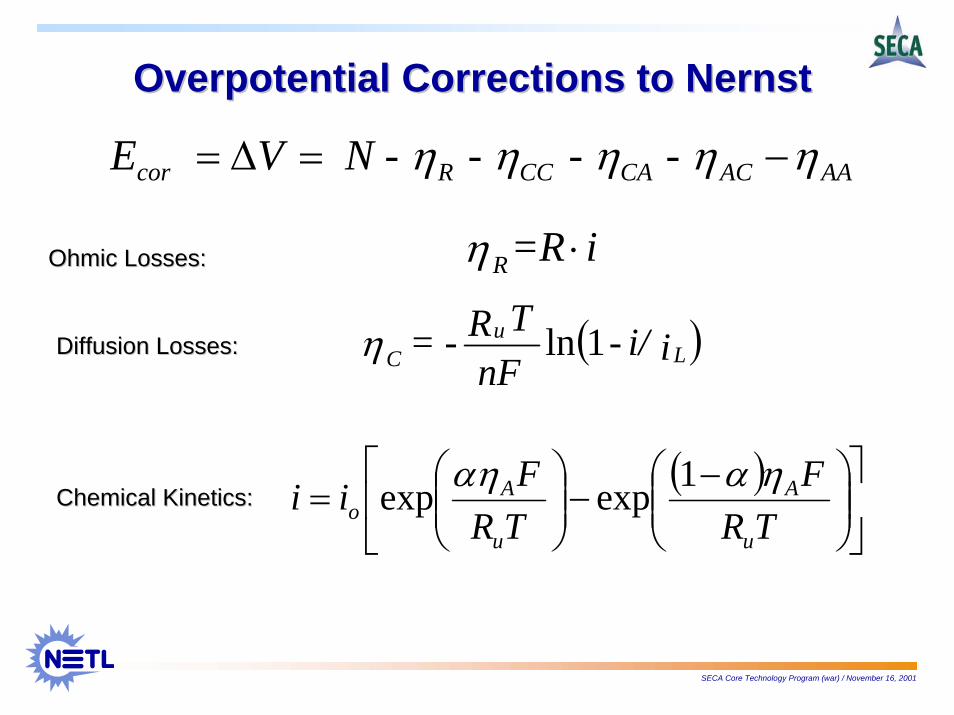
OverpotentialOverpotential Corrections to NernstCorrections to Nernst
AAACCACCRcor - - - N - V E ηηηηη −=Δ=
i=RR ⋅η
( )ii/-nF
TR-= Lu
C 1lnη
( )⎥⎦
⎤⎢⎣
⎡⎟⎟⎠
⎞⎜⎜⎝
⎛ −−⎟⎟⎠
⎞⎜⎜⎝
⎛=
TRF
TRFii
u
A
u
Ao
ηααη 1expexp
Ohmic Losses:Ohmic Losses:
Diffusion Losses:Diffusion Losses:
Chemical Kinetics:Chemical Kinetics:
SECA Core Technology Program (war) / November 16, 2001
NETL SOFC ModelNon-Proprietary Examples
•• Tube Geometry Tube Geometry
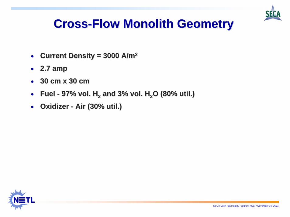
•• CrossflowCrossflow -- MonolithMonolith
•• Single Single -- Channel MonolithChannel Monolith
SECA Core Technology Program (war) / November 16, 2001
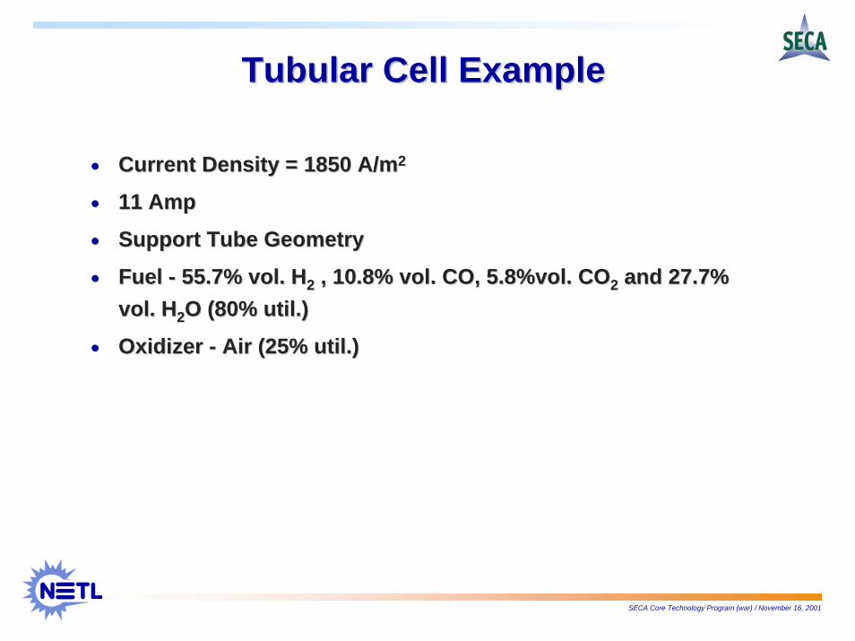
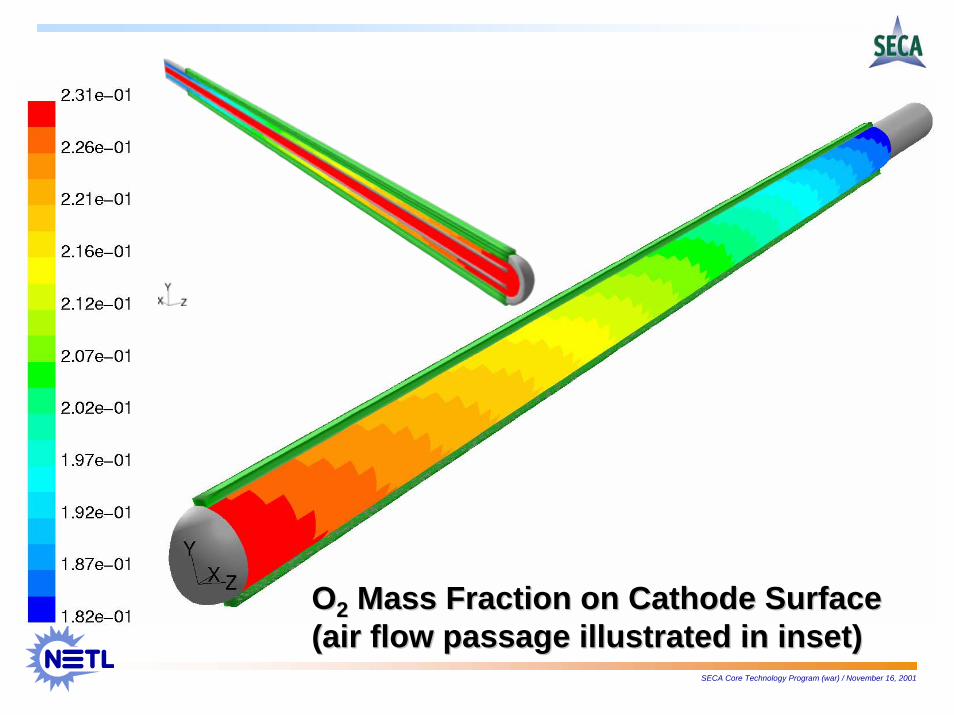
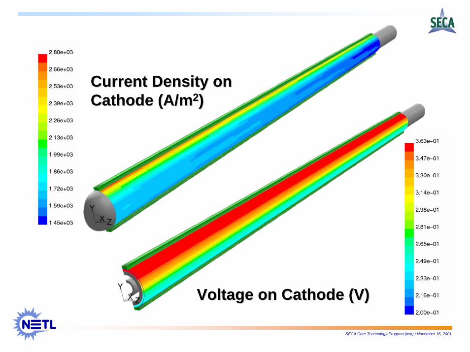
Tubular Cell ExampleTubular Cell Example
•• Current Density = 1850 A/mCurrent Density = 1850 A/m22
•• Current Density = 3000 A/mCurrent Density = 3000 A/m22
•• 2.7 amp2.7 amp
•• 30 cm x 30 cm30 cm x 30 cm
•• Fuel Fuel -- 97% vol. H97% vol. H22 and 3% vol. Hand 3% vol. H22O (80% util.)O (80% util.)
•• Oxidizer Oxidizer -- Air (30% util.)Air (30% util.)
SECA Core Technology Program (war) / November 16, 2001
Anode Current CollectorAnode Current Collector
Cathode Cathode Current Current CollectorCollector
CathodeCathode
AnodeAnode
ElectrolyteElectrolyte
Fuel InFuel In
Fuel OutFuel OutOxidizer InOxidizer In
Oxidizer Oxidizer OutOut
SECA Core Technology Program (war) / November 16, 2001
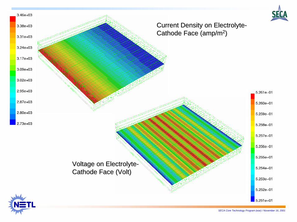
Current Density on ElectrolyteCurrent Density on Electrolyte--Cathode Face (amp/mCathode Face (amp/m22))
Voltage on ElectrolyteVoltage on Electrolyte--Cathode Face (Volt)Cathode Face (Volt)
SECA Core Technology Program (war) / November 16, 2001
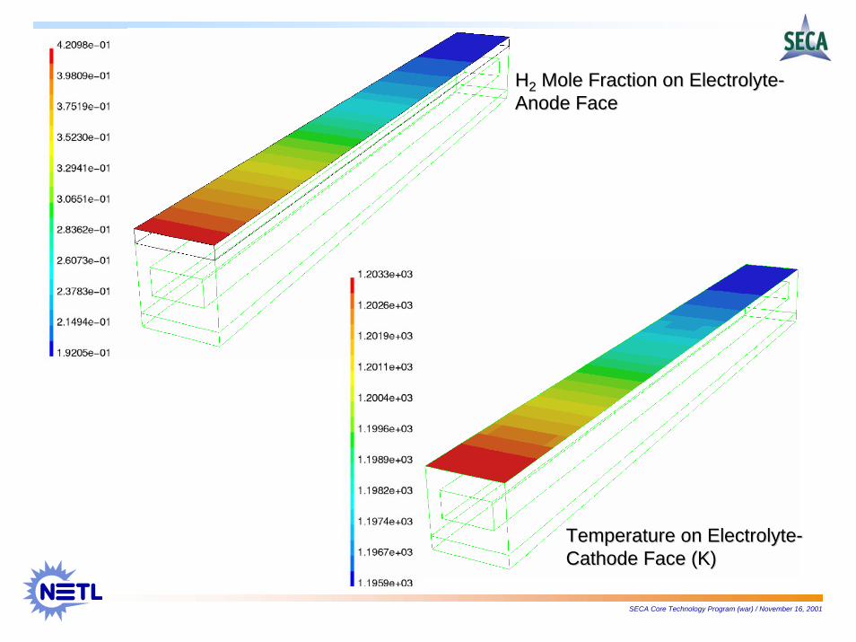
Temperature on ElectrolyteTemperature on Electrolyte--Cathode Face (K)Cathode Face (K)
HH22 Mole Fraction Mole Fraction on Electrolyteon Electrolyte--Anode FaceAnode Face
SECA Core Technology Program (war) / November 16, 2001
CoCo--Flow Monolith ChannelFlow Monolith Channel
•• Current Density = 3000 A/mCurrent Density = 3000 A/m22
•• 0.27 amp0.27 amp
•• 30 cm x 3mm30 cm x 3mm
•• Fuel Fuel -- 97% vol. H97% vol. H22 and 3% vol. Hand 3% vol. H22O (80% util.)O (80% util.)
•• Oxidizer Oxidizer -- Air (30% util.)Air (30% util.)
•• Couple with ANSYSCouple with ANSYS
SECA Core Technology Program (war) / November 16, 2001
Anode Current CollectorAnode Current Collector
Cathode Current Cathode Current CollectorCollector
CathodeCathodeAnodeAnode
Electrolyte
Fuel InFuel In
Fuel OutFuel Out
Oxidizer InOxidizer In
Oxidizer Oxidizer OutOut
SECA Core Technology Program (war) / November 16, 2001
Current Density on ElectrolyteCurrent Density on Electrolyte--Cathode Face (Amp/m2)Cathode Face (Amp/m2)
Voltage on ElectrolyteVoltage on Electrolyte--Cathode Face (Volt)Cathode Face (Volt)
SECA Core Technology Program (war) / November 16, 2001
HH22 Mole Fraction on ElectrolyteMole Fraction on Electrolyte--Anode FaceAnode Face
Temperature on ElectrolyteTemperature on Electrolyte--Cathode Face (K)Cathode Face (K)
SECA Core Technology Program (war) / November 16, 2001
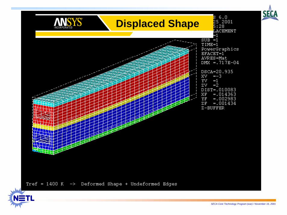
Displaced Shape
SECA Core Technology Program (war) / November 16, 2001
Displacement
SECA Core Technology Program (war) / November 16, 2001
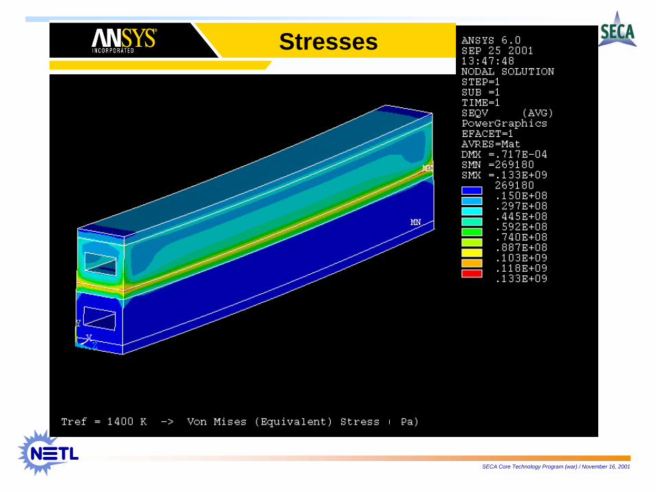
Stresses
SECA Core Technology Program (war) / November 16, 2001
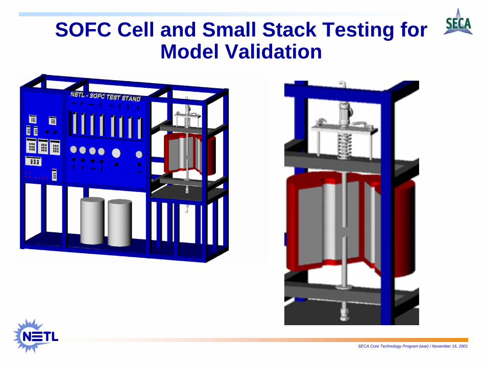
SOFC Cell and Small Stack Testing for Model Validation
SECA Core Technology Program (war) / November 16, 2001
Technical Approach•• Collaborate with cell/stack developers that can provide Collaborate with cell/stack developers that can provide ‘‘genericgeneric--
customizedcustomized’’ test specimenstest specimens
•• Partner with labs capable of property analysisPartner with labs capable of property analysis−− Single & composite material analysisSingle & composite material analysis−− Porous media characterizationPorous media characterization−− Post test analysis (ensure consistent and proper operation of spPost test analysis (ensure consistent and proper operation of specimens ecimens
under test)under test)
•• Work closely with model developers to ensure data relevancy for Work closely with model developers to ensure data relevancy for model model validation purposesvalidation purposes
•• Redundant testingRedundant testing
SECA Core Technology Program (war) / November 16, 2001
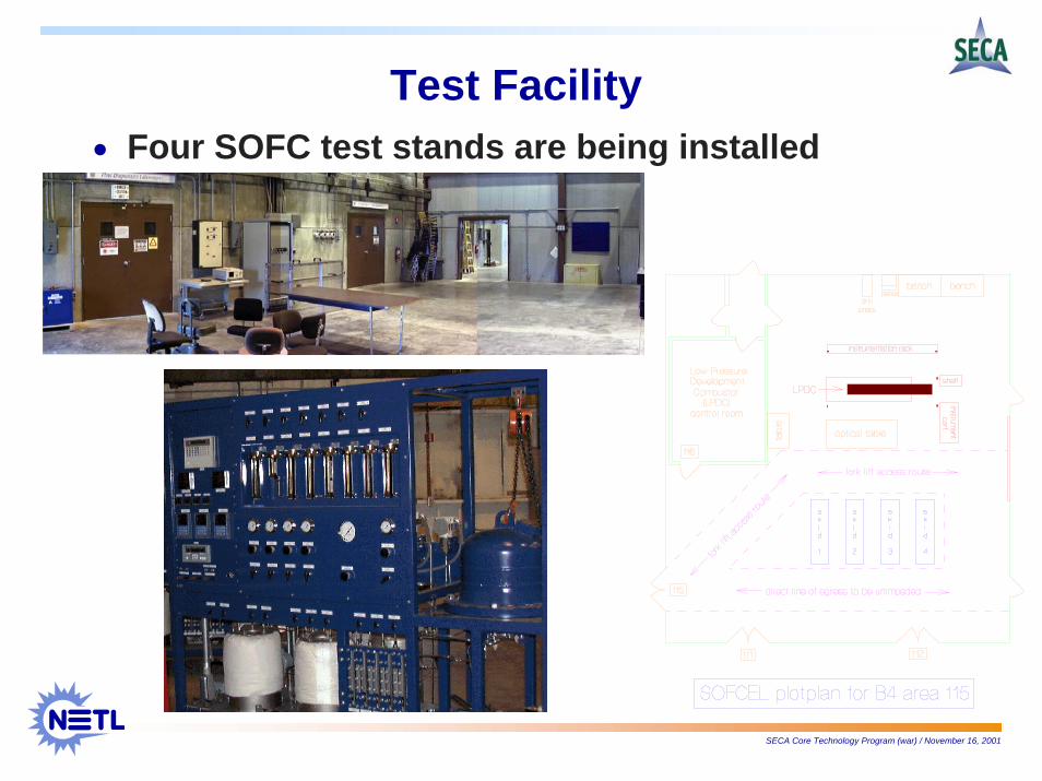
Test Facility• Four SOFC test stands are being installed
SECA Core Technology Program (war) / November 16, 2001
Specimen Test FixturesSpecimen Test Fixtures•• Model validation using different flow conditions:Model validation using different flow conditions:
−−Stagnant environmentStagnant environment
Humidified H2
FurnaceWall
PEN
Ambient Air (Diffusion
Driven)
SupportTube
Spent H2
Humidified H2
Humidified Air
PEN
−−Convective environmentConvective environment
SECA Core Technology Program (war) / November 16, 2001
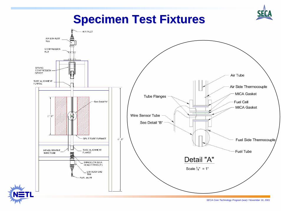
Specimen Test FixturesSpecimen Test Fixtures
SECA Core Technology Program (war) / November 16, 2001
•• NETL/Fluent Incorporated CRADA for fuel cell model NETL/Fluent Incorporated CRADA for fuel cell model development and validation (11/14/01)development and validation (11/14/01)
•• Fluent plans to offer commercial versions of SOFC and Fluent plans to offer commercial versions of SOFC and PEMFC models in 2nd Quarter 2002PEMFC models in 2nd Quarter 2002
SECA Core Technology Program (war) / November 16, 2001
•• SECA Prototype Test FacilitySECA Prototype Test Facility
−− Periodically assess progress in meeting SECA Fuel Cell Periodically assess progress in meeting SECA Fuel Cell Program GoalsProgram Goals
−− Independently test each prototype system at NETL under well Independently test each prototype system at NETL under well controlled and monitored conditionscontrolled and monitored conditions
−− Report technical performance to SECA managersReport technical performance to SECA managers
SECA Core Technology Program (war) / November 16, 2001