20
Network Analysis Short-Circuit – ANSI Short-Circuit – IEC Arc Flash Load Flow Motor Acceleration CUSTOMIZABLE INTEGRATED MODULAR

Network Analysis
Short-Circuit – ANSIShort-Circuit – IEC
Arc FlashLoad Flow
Motor Acceleration
CUSTOMIZABLE
INTEGRATED
MODULAR

Power System Enterprise SolutionETAP is the most comprehensive analysis platform for the design, simulation, operation, control, optimization, and automation of generation, transmission, distribution, and industrial power systems.
2 |

Ground Grid Systems
Finite Element MethodIEEE 80 & 665 Methods
Transmission Line
Line ConstantsLine AmpacitySag & Tension
HV DC Transmission Link
Base Package
Cable Ampacity & SizingTransmission Line Constants
Report ManagerProject Management Wizards
Output Report ComparatorMulti-D Database
Libraries
Data Exchange
DataXMS Access & Excel
CAD Interfacee-DPP Interface
SmartPlant Interface
DC Systems Load Flow
Short-CircuitControl System Diagram
Battery DischargeBattery Sizing
ARTTS Relay Testing & Simulation
Relay Test Set EquipmentETAP Test Set Software
Cable Systems Underground Thermal Analysis
Cable PullingCable Ampacity
Cable SizingSTAR
Protective Devices
Coordination & SelectivitySequence-of-OperationRelay Test Set Interface
Dynamics & Transients
Transient StabilityGenerator Start-Up
Wind Turbine GeneratorUser-Defined Dynamic Model
Parameter Estimation
Distribution Unbalanced Load Flow
Optimal Power FlowTransformer Tap OptimizationSwitching Sequence Mgmt.
Reliability AssessmentOptimal Capacitor Placement
GIS Map
Energy Management
System Automatic Generation Control
Economic DispatchSupervisory Control
Interchange SchedulingReserve Management
Power QualityHarmonic Load Flow
Frequency ScanHarmonic FiltersNetwork
Analysis Short-Circuit – ANSIShort-Circuit – IEC
Arc FlashLoad Flow
Motor Acceleration
Panel SystemsPanels ANSI & IEC
Customize ETAP to fit your needs, from small to large power systems
Monitoring & SimulationAdvanced MonitoringEnergy Accounting
Real-Time SimulationEvent Playback
Load Forecasting
Intelligent Load Shedding
Load PreservationLoad Restoration
Load Shedding Validation
Intelligent Substation
Substation AutomationSwitching Management
Load Management
| 3
ETAP Enterprise Suite provides one solution to your power system
design, analysis, and operation needs. ETAP offers a comprehensive
suite of analysis modules that can be configured to suit your specific
needs. This modular approach allows you to purchase only the
modules you need.
FEATURED IN THIS BROCHURE
ANSI / IEEE Standards C37 & UL 489
IEC Standards 60909 & 61363
Automatic Device Evaluation for 3-Phase, 1-Phase, & Panel Systems
Load Terminal Short Circuit Calculation
Display Critical & Marginal Alerts
Integrates with Star Protective Device Coordination
Seamless Transition to Arc Flash
Instant Results, Comprehensive, Graphical Summary
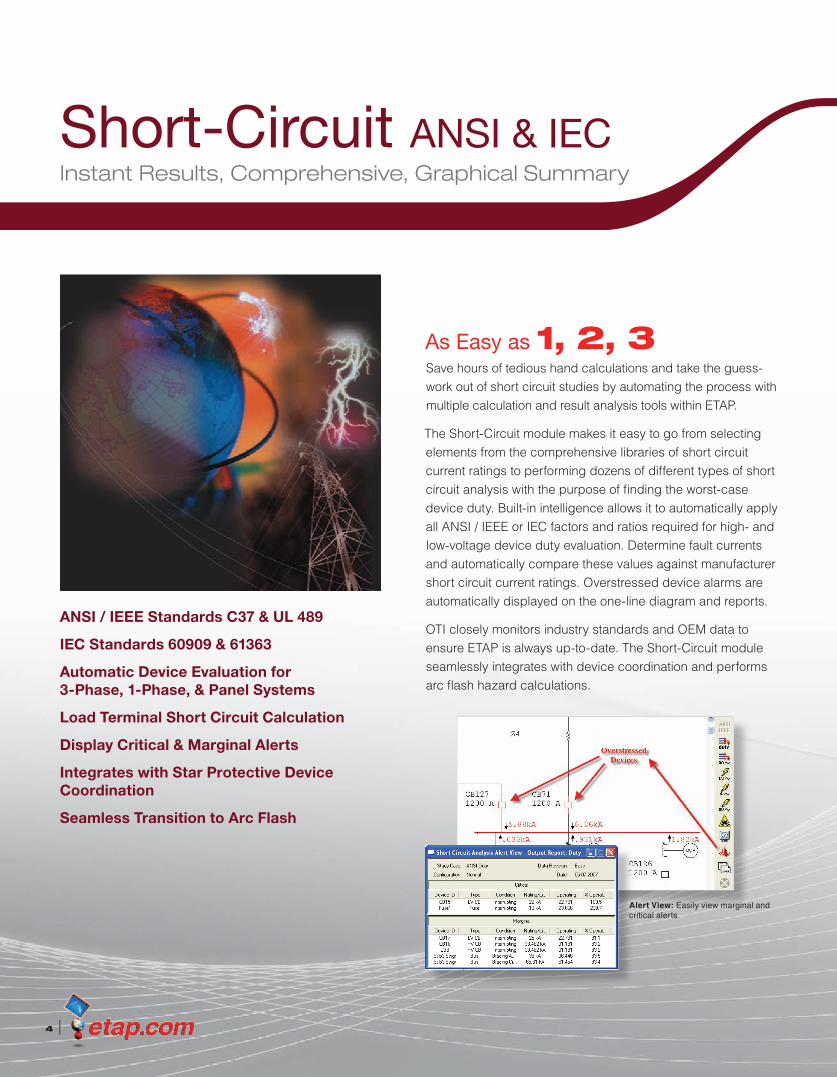
As Easy as 1, 2, 3Save hours of tedious hand calculations and take the guess- work out of short circuit studies by automating the process with multiple calculation and result analysis tools within ETAP.
The Short-Circuit module makes it easy to go from selecting elements from the comprehensive libraries of short circuit current ratings to performing dozens of different types of short circuit analysis with the purpose of finding the worst-case device duty. Built-in intelligence allows it to automatically apply all ANSI / IEEE or IEC factors and ratios required for high- and low-voltage device duty evaluation. Determine fault currents and automatically compare these values against manufacturer short circuit current ratings. Overstressed device alarms are automatically displayed on the one-line diagram and reports.
OTI closely monitors industry standards and OEM data to ensure ETAP is always up-to-date. The Short-Circuit module seamlessly integrates with device coordination and performs arc flash hazard calculations.
Short-Circuit ANSI & IEC
4 |
Alert View: Easily view marginal and critical alerts

Short-Circuit ANSI & IEC | 5
Device Duty Calculation & Evaluation for Single & Multiple-Phase Systems, Panel, & UPSANSI and IEC standards are used for calculating short circuit current for parts of the network below main panels, subpanels, UPS, and phase adapters. Device duty calculation compares the calculated fault current from these networks for evaluation of protective devices and automatically generates critical and marginal alerts based on user-defined alarm limits.
Panel Systems
UPS Systems
Multi-Phase Systems
Capabilities• Automatic 3-phase device evaluation
• Device evaluation based on total or maximum through fault current
• Automatically adjust conductor resistance & length (both lines & cables)
• Global or individual device impedance tolerance adjustments for maximum & minimum fault currents
• Include / exclude fault impedance modeling for unbalanced faults
• Include / exclude shunt admittance for branches & capacitive loads (unbalanced faults)
• Graphical or tabular bus fault selections
• Automatically determine fault currents at motor terminals without the need to add additional buses
• Phase-shifting transformers
• Grounding models for generators, transformers, motors, & other loads
• Motor contribution based on loading category, demand factor, or both
• Extract manufacturer published data from the libraries for thousands of devices

ANSI / IEEE Standards
6 |
Features• 1-phase & panel systems device evaluation
• Determine maximum & minimum short circuit fault currents
• Calculate ½ cycle, 1.5–4, & 30 cycle balanced & unbalanced faults (3-phase, L-G, L-L, L-L-G)
• Check momentary & interrupting device capabilities
• Check closing & latching capabilities
• Evaluate symmetrical or total rated circuit breakers
• Special handling of generator circuit breakers for system & generator faults
• Interrupting duty as a function breaker contact parting time
• Standard & user-definable contact parting time
• Automatically includes No AC Decay (NACD) ratio
• User options for automatic adjustment of HVCB rating
StandardsIEEE C37.04 Standard Rating Structure for AC High-Voltage Circuit Breakers
Rated on a Symmetrical Current including Supplements: IEEE C37.04f, IEEE C37.04g, IEEE C37.04h, IEEE C37.04i
IEEE C37.010 Standard Application Guide for AC High-Voltage Circuit Breakers Rated on a Symmetrical Current
IEEE C37.010b Standard and Emergency Load Current-Carrying Capability
IEEE C37.010e Supplement to IEEE C37.010
IEEE C37.13 Standard for Low-Voltage AC Power Circuit Breakers Used in Enclosures
IEEE C37.013 Standard for AC High-Voltage Generator Circuit Breakers Rated on a Symmetrical Current Basis
IEEE C37.20.1 Standard for Metal Enclosed Low-Voltage Power Circuit Breaker Switchgear
IEEE 399 Power System Analysis – the Brown Book
IEEE 141 Electric Power Distribution for Industrial Plants – the Red Book
IEEE 242 IEEE Recommended Practice for Protection and Coordination of Industrial and Commercial Power Systems – the Buff Book
UL 489_9 Standard for Safety for Molded-Case Circuit Breakers, Molded-Case Switches, and Circuit Breaker Enclosures
Reporting (ANSI & IEC)• Load terminal fault current reporting
• Automatically flag marginal & critical overstressed devices
• Individual fault current contributions for Isym, Ia, & 3I0
• Phase & sequence voltage profiles (Va, Vb, Vc, V1, V2, & V0)
• Phase & sequence current profiles (Ia, Ib, Ic, I1, I2, & I0)
• Phase & sequence impedances
• Alert view to display critical & marginal limit violations
• Export one-lines with short circuit results to third party CAD applications
• Input data, detailed individual & total short circuit contributions, & summaries
• Enhanced state-of-the-art graphic display of results for balanced & unbalanced faults
• Export output reports to your favorite word processor or spreadsheet
• Full color customizable Crystal Report® viewers
Reporting: Load terminal fault current reporting

IEC Standards
Short-Circuit ANSI & IEC | 7
Features• 1-pole / 2-pole short circuit device duty for 1-phase
panel / UPS systems
• Unbalanced L-G, L-L, & L-L-G faults analysis
• Transient IEC 61363 short circuit calculations
• Compares device ratings with calculated short circuit values
• User-definable voltage C factor
• Service or ultimate short circuit current ratings for LVCB breaking capability
• User-definable R/X adjustment methods for Ip (method A, B, or C)
• Phase-shifting transformers
• Negative or positive impedance adjustments for max/min I˝k & Ik
• Automatic application of K correction factors (i.e., KT, KG, KSO)
• Automatically determines meshed & non-meshed networks for calculating Ib, Ik, & Idc
• Ib for meshed network is adjusted by individual machine contributions for improved accuracy
• Considers both near & far from generator short circuits
• Generates relay test set compatible plots for transient short circuits
• Detailed IEC device duty reports & complete contributions for unbalanced faults
StandardsIEC 62271-100 High-Voltage Switchgear and Controlgear,
Part 100:High-Voltage Alternating-Current Circuit Breakers
IEC 62271-200 High-Voltage Switchgear and Controlgear, Part 200: AC Metal-Enclosed Switchgear and Controlgear for Rated Voltages Above 1 kV and up to and including 52 kV
IEC 62271-203 High-Voltage Switchgear and Controlgear, Part 203: Gas-Insulated Metal-Enclosed Switchgear for Rated Voltages Above 52 kV
IEC 60282-2 High-Voltage Fuses, Part 2: Expulsion Fuses
IEC 60909-0 Short Circuit Currents in Three-Phase AC Systems, Part 0: Calculation of Currents (including 2002 Corrigendum 1)
IEC 60909-1 Short Circuit Currents in Three-Phase AC Systems, Part 1: Factors for the Calculation of Short Circuit Currents According to IEC 60909-0
IEC 60909-2 Electrical Equipment – Data for Short Circuit Current Calculations in Accordance with IEC 909 (1988)
IEC 60909-4 Short Circuit Currents in Three-Phase AC Systems, Part 4: Examples for the Calculation of Short Circuit Currents
IEC 60947-1 Low Voltage Switchgear and Controlgear, Part 1: General Rules
IEC 60947-2 Low Voltage Switchgear and Controlgear, Part 2: Circuit Breakers
IEC 61363-1 Electrical Installations of Ships and Mobile and Fixed Offshore Units, Part 1: Procedures for Calculating Short Circuit Currents in Three-Phase AC
Fault Current Waveform

IEEE 1584a 2004
NFPA 70E 2000 & 2004
Enclosed & Open Air Equipment Arc Flash Calculations
Integrated with ETAP Short-Circuit
Integrated with ETAP Star Protective Device Coordination
Reduce Risk, Improve Safety, Enforce Compliance
Arc Flash Analysis
8 |
Industry Leader in Comprehensive Arc Flash SolutionsETAP Arc Flash Analysis brings you new and enhanced capabilities which allow for faster and easier performance of arc flash hazard analysis. Identify and analyze high risk arc flash areas in your electrical system with greater flexibility by simulating various incident energy mitigation methods.
Arc Flash is a completely integrated module that solves multiple scenarios to determine worst-case incident energy levels. It also produces professional reports and high quality arc flash labels at the press of a button.
One-Line Diagram: TCC and arc flash results
Most Capable & User-Friendly Arc Flash Hazard Assessment Solution
Arc Flash Analysis | 9
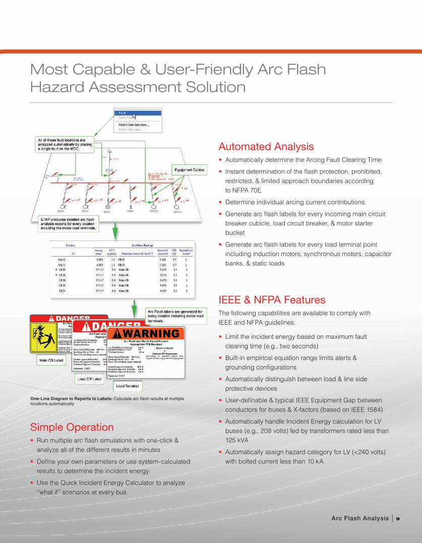
One-Line Diagram to Reports to Labels: Calculate arc flash results at multiple locations automatically
IEEE & NFPA FeaturesThe following capabilities are available to comply with IEEE and NFPA guidelines:
• Limit the incident energy based on maximum fault clearing time (e.g., two seconds)
• Built-in empirical equation range limits alerts & grounding configurations
• Automatically distinguish between load & line side protective devices
• User-definable & typical IEEE Equipment Gap between conductors for buses & X-factors (based on IEEE 1584)
• Automatically handle Incident Energy calculation for LV buses (e.g., 208 volts) fed by transformers rated less than 125 kVA
• Automatically assign hazard category for LV (<240 volts) with bolted current less than 10 kA
Simple Operation• Run multiple arc flash simulations with one-click &
analyze all of the different results in minutes
• Define your own parameters or use system-calculated results to determine the incident energy
• Use the Quick Incident Energy Calculator to analyze “what if” scenarios at every bus
Automated Analysis• Automatically determine the Arcing Fault Clearing Time
• Instant determination of the flash protection, prohibited, restricted, & limited approach boundaries according to NFPA 70E
• Determine individual arcing current contributions
• Generate arc flash labels for every incoming main circuit breaker cubicle, load circuit breaker, & motor starter bucket
• Generate arc flash labels for every load terminal point including induction motors, synchronous motors, capacitor banks, & static loads
Comprehensive Arc Flash Safety Program
10 |
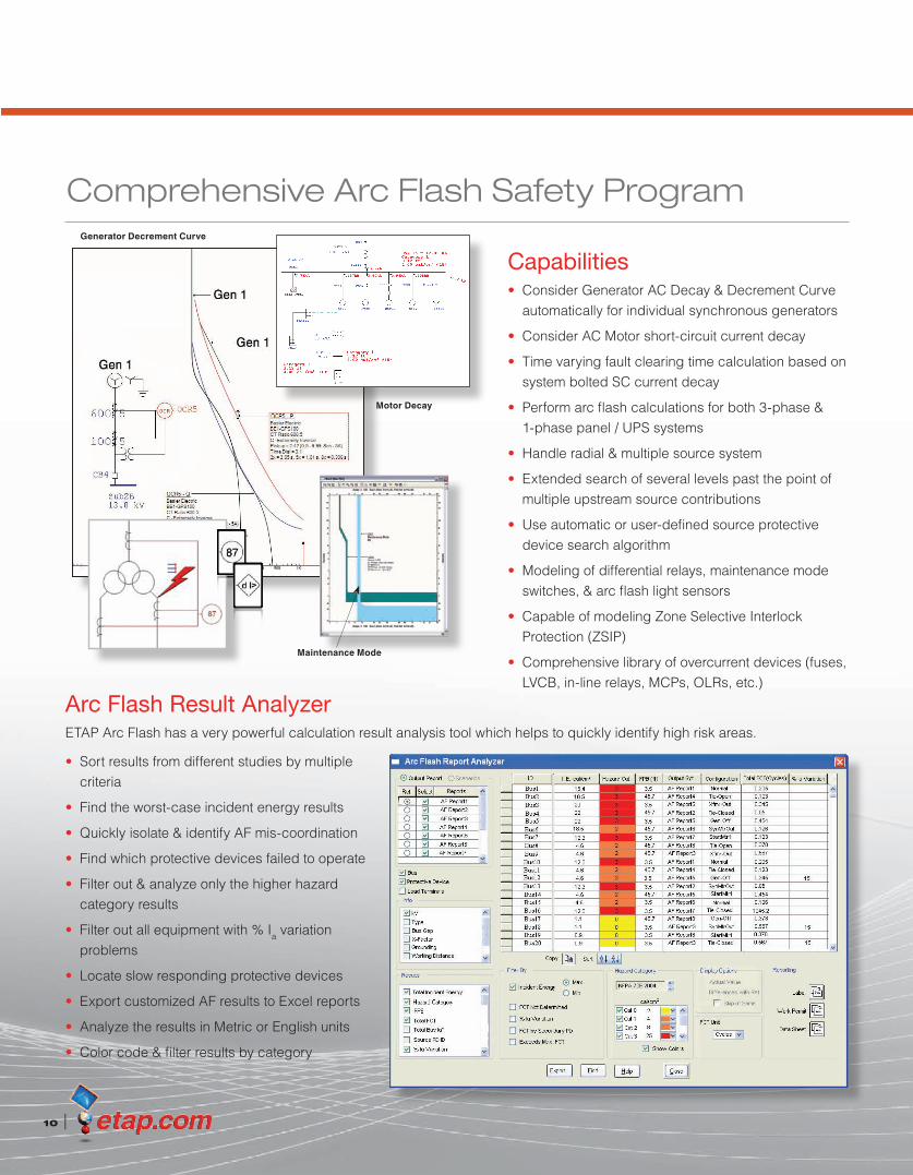
Maintenance Mode
Motor Decay
Arc Flash Result AnalyzerETAP Arc Flash has a very powerful calculation result analysis tool which helps to quickly identify high risk areas.
Capabilities• Consider Generator AC Decay & Decrement Curve
automatically for individual synchronous generators
• Consider AC Motor short-circuit current decay
• Time varying fault clearing time calculation based on system bolted SC current decay
• Perform arc flash calculations for both 3-phase & 1-phase panel / UPS systems
• Handle radial & multiple source system
• Extended search of several levels past the point of multiple upstream source contributions
• Use automatic or user-defined source protective device search algorithm
• Modeling of differential relays, maintenance mode switches, & arc flash light sensors
• Capable of modeling Zone Selective Interlock Protection (ZSIP)
• Comprehensive library of overcurrent devices (fuses, LVCB, in-line relays, MCPs, OLRs, etc.)
• Sort results from different studies by multiple criteria
• Find the worst-case incident energy results
• Quickly isolate & identify AF mis-coordination
• Find which protective devices failed to operate
• Filter out & analyze only the higher hazard category results
• Filter out all equipment with % Ia variation problems
• Locate slow responding protective devices
• Export customized AF results to Excel reports
• Analyze the results in Metric or English units
• Color code & filter results by category
Generator Decrement Curve
Work Permits, Data Sheets, Labels, . . .
Reporting• Calculated results are displayed automatically on the
one-line diagram
• Printing of ANSI Z535 arc flash label templates with user-defined text fields / PPE requirements / disclaimers
• Print assorted sizes (4"x 6", 4"x 4", 3"x 3") of arc flash labels to Brady® Label printers or DuraLabel® Pro printers
• Print arc flash labels to Avery® Permanent Durable ID templates
• Print labels in multiple languages, such as Spanish, Portuguese, & French
• Plot incident energy vs. time & arcing current in Star (for coordination)
• MS Excel reports for bus & individual protective device arc flash analysis results
• Hundreds of customizable arc flash label templates are available
Arc Flash Analysis | 11
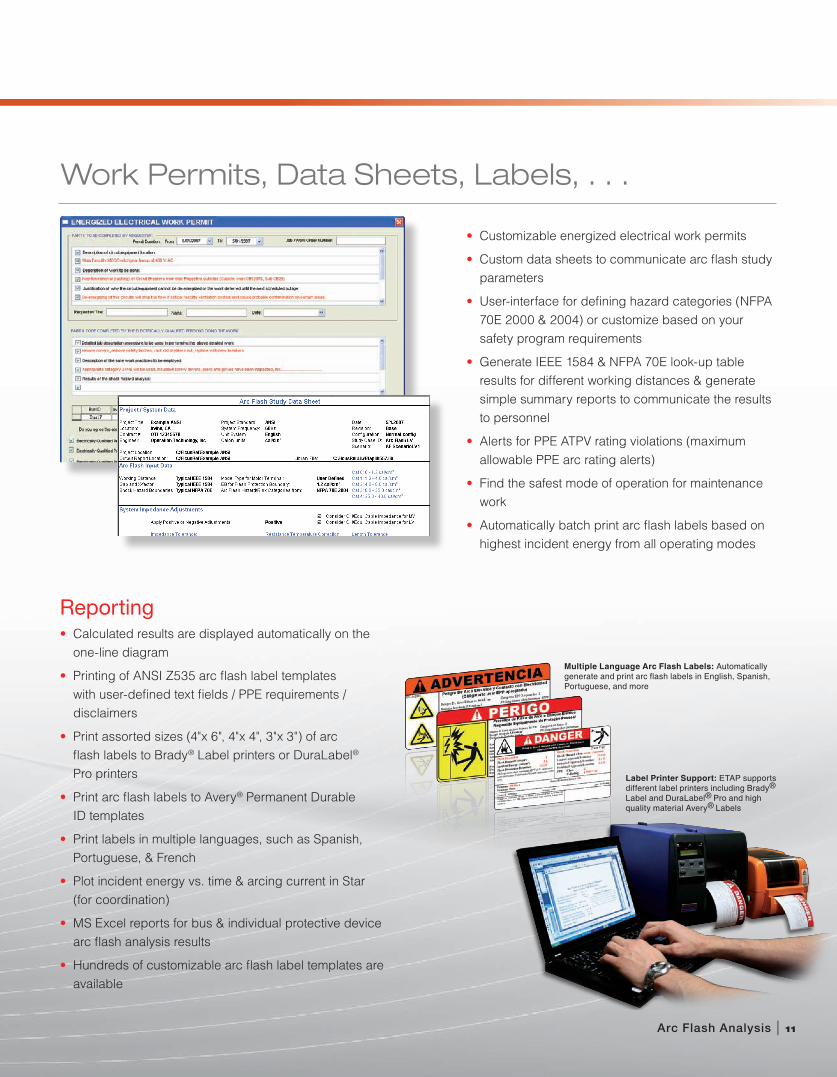
Label Printer Support: ETAP supports different label printers including Brady® Label and DuraLabel® Pro and high quality material Avery® Labels
Multiple Language Arc Flash Labels: Automatically generate and print arc flash labels in English, Spanish, Portuguese, and more
• Customizable energized electrical work permits
• Custom data sheets to communicate arc flash study parameters
• User-interface for defining hazard categories (NFPA 70E 2000 & 2004) or customize based on your safety program requirements
• Generate IEEE 1584 & NFPA 70E look-up table results for different working distances & generate simple summary reports to communicate the results to personnel
• Alerts for PPE ATPV rating violations (maximum allowable PPE arc rating alerts)
• Find the safest mode of operation for maintenance work
• Automatically batch print arc flash labels based on highest incident energy from all operating modes

Voltage Drop
Power Factor Correction
Automatic Device Evaluation
Automatic Temperature Correction
2W & 3W Transformer LTC / Regulator Actions
Real & Reactive Power Losses
Extensive Violation Alerts
Multi-Report Result Analyzer
One Program, One Database, One Solution
Create & Validate System Models with Ease & AccuracyWith ETAP’s advanced Load Flow module, you can create and validate your system model with ease and obtain accurate and reliable results. Built-in features like automatic device evaluation, summary alarms / warnings, result analyzer, and intelligent graphics make it the most efficient Load Flow program available today.
ETAP calculates bus voltages, branch power factors, currents, and power flows throughout the electrical system. ETAP allows for swing, voltage regulated, and unregulated power sources with multiple power grids and generator connections. It is capable of performing analysis on both radial and loop systems. ETAP allows you to select from several different methods in order to achieve the best calculation efficiency and accuracy.
Load Flow Analysis
Intelligent Graphics: State-of-the-art graphical display of results including voltage drop, load terminal voltage, branch losses, and transformer LTC settings
12 |
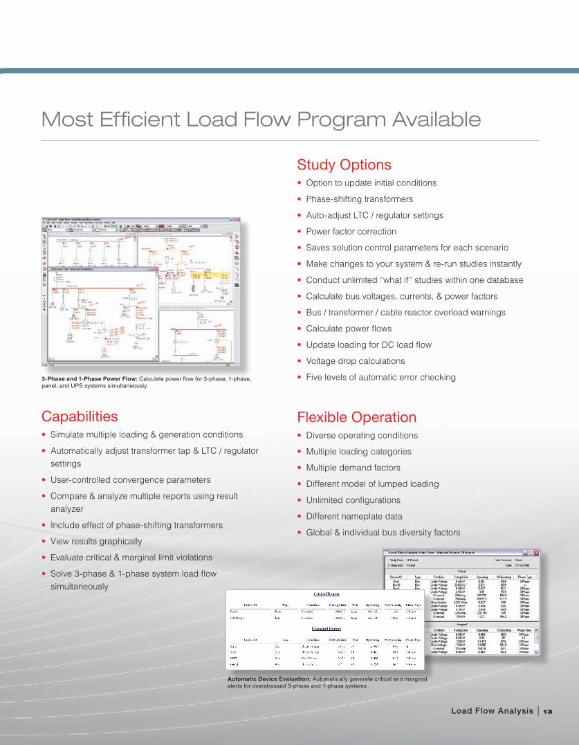
Most Efficient Load Flow Program Available
Load Flow Analysis | 13
Capabilities• Simulate multiple loading & generation conditions
• Automatically adjust transformer tap & LTC / regulator settings
• User-controlled convergence parameters
• Compare & analyze multiple reports using result analyzer
• Include effect of phase-shifting transformers
• View results graphically
• Evaluate critical & marginal limit violations
• Solve 3-phase & 1-phase system load flow simultaneously
Automatic Device Evaluation: Automatically generate critical and marginal alerts for overstressed 3-phase and 1-phase systems
3-Phase and 1-Phase Power Flow: Calculate power flow for 3-phase, 1-phase, panel, and UPS systems simultaneously
Study Options• Option to update initial conditions
• Phase-shifting transformers
• Auto-adjust LTC / regulator settings
• Power factor correction
• Saves solution control parameters for each scenario
• Make changes to your system & re-run studies instantly
• Conduct unlimited “what if” studies within one database
• Calculate bus voltages, currents, & power factors
• Bus / transformer / cable reactor overload warnings
• Calculate power flows
• Update loading for DC load flow
• Voltage drop calculations
• Five levels of automatic error checking
Flexible Operation• Diverse operating conditions
• Multiple loading categories
• Multiple demand factors
• Different model of lumped loading
• Unlimited configurations
• Different nameplate data
• Global & individual bus diversity factors
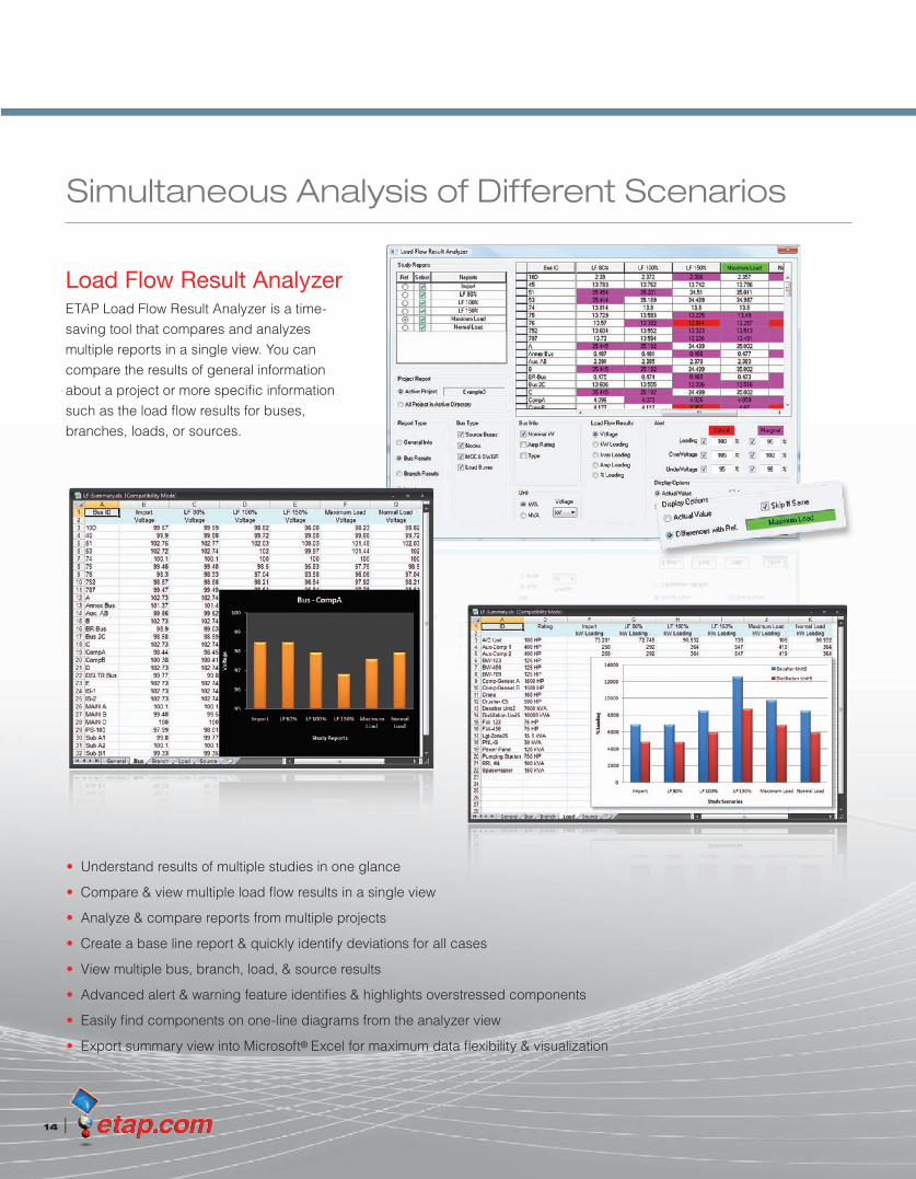
Simultaneous Analysis of Different Scenarios
14 |
Load Flow Result AnalyzerETAP Load Flow Result Analyzer is a time-saving tool that compares and analyzes multiple reports in a single view. You can compare the results of general information about a project or more specific information such as the load flow results for buses, branches, loads, or sources.
• Understand results of multiple studies in one glance
• Compare & view multiple load flow results in a single view
• Analyze & compare reports from multiple projects
• Create a base line report & quickly identify deviations for all cases
• View multiple bus, branch, load, & source results
• Advanced alert & warning feature identifies & highlights overstressed components
• Easily find components on one-line diagrams from the analyzer view
• Export summary view into Microsoft® Excel for maximum data flexibility & visualization
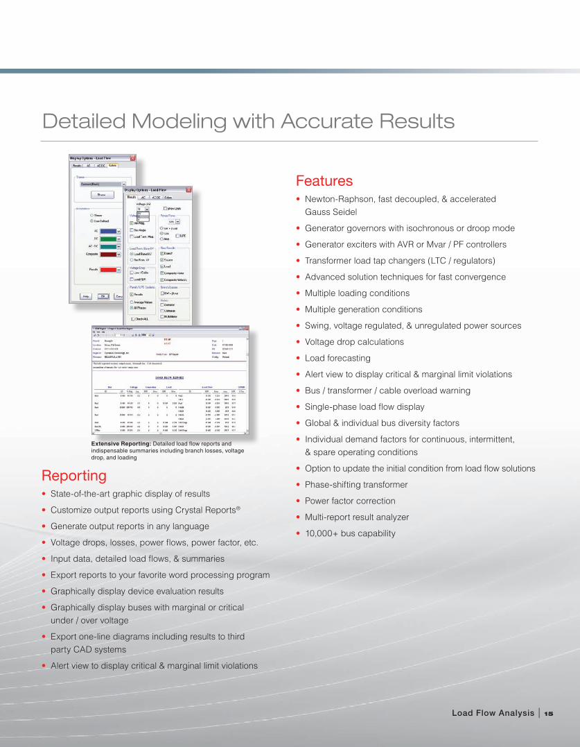
Detailed Modeling with Accurate Results
Reporting• State-of-the-art graphic display of results
• Customize output reports using Crystal Reports®
• Generate output reports in any language
• Voltage drops, losses, power flows, power factor, etc.
• Input data, detailed load flows, & summaries
• Export reports to your favorite word processing program
• Graphically display device evaluation results
• Graphically display buses with marginal or critical under / over voltage
• Export one-line diagrams including results to third party CAD systems
• Alert view to display critical & marginal limit violations
Features• Newton-Raphson, fast decoupled, & accelerated
Gauss Seidel
• Generator governors with isochronous or droop mode
• Generator exciters with AVR or Mvar / PF controllers
• Transformer load tap changers (LTC / regulators)
• Advanced solution techniques for fast convergence
• Multiple loading conditions
• Multiple generation conditions
• Swing, voltage regulated, & unregulated power sources
• Voltage drop calculations
• Load forecasting
• Alert view to display critical & marginal limit violations
• Bus / transformer / cable overload warning
• Single-phase load flow display
• Global & individual bus diversity factors
• Individual demand factors for continuous, intermittent, & spare operating conditions
• Option to update the initial condition from load flow solutions
• Phase-shifting transformer
• Power factor correction
• Multi-report result analyzer
• 10,000+ bus capability
Load Flow Analysis | 15
Extensive Reporting: Detailed load flow reports and indispensable summaries including branch losses, voltage drop, and loading

Dynamic Motor Acceleration
Static Motor Starting
Voltage Flicker
Motor & Load Dynamic Models
Conventional & Soft Starting Devices
Multi-Sequence Starting
Load & Generation Transitioning
Comprehensive Alarm & Warning
Motor Operated Valve (MOV) Simulation
Intuitive, Intelligent, Incomparable
Advanced Technology in Motor Evaluation & SimulationThe Motor Acceleration module enables engineers to thoroughly evaluate the impact of load changes to electric power systems. Motor Acceleration is fully capable of starting one motor or transitioning an entire power system to another state. Sequence-start a series of machines using static or dynamic models, operate Motor Operated Valves (MOVs), and simulate the switching actions of Load Tap Changers. Advanced plotting and time varying graphical display enable engineers to quickly evaluate results and make decisions.
Motor Acceleration
16 |
Accelerate Multiple Motors: Start multiple motors using unlimited sequence of events

Quickly Evaluate Results & Make Decisions
Motor Acceleration | 17
Capabilities• Accelerate / stop multiple motors
• Dynamically model motors & loads
• Create unlimited sequence of events
• Compare the response from various motor starters
• Simulate load ramping of starting motor
• Transition loading of entire system
• Vary generator / grid operating parameters
• Visualize results with extensive alerts & warnings
• Simulate transformer LTCs / voltage regulators
• Simulate MOVs with five operating stages
Comprehensive Modeling• No voltage or system connection limitations
• Induction / synchronous motor dynamic models
• Typical & user-defined load models
• Global or individual LTC time delays
• Transformer phase shift
• Starting devices: auto-transformer, capacitor, rotor / stator R or X, Y/D, partial winding, etc.
• Voltage, current, or torque controlled soft starters
• Five levels of automatic error checking
Motor Starting Time Slider: View time domain results graphically
Dynamic Modeling: Complete modeling of machines and connected load

Reporting• Graphical display of time-varying results
• Auto-alert abnormal conditions with marginal or critical levels
• Graphically display buses with marginal or critical voltage levels
• Comprehensive plots with operation details
• Export one-line diagrams including results to third party CAD systems
• Export to your favorite word processing program
18 |
Comprehensive Reporting: Customizable output reports using Crystal Reports®
User-Defined Alerts: Automatically flag marginal and overstressed devices
Realistic Operation: Simulate load and generation transitioning
Automatic Result Validation / Alert• Motor start failure
• Under-voltage for starting motor / MOV
• Under-voltage buses per bus type & voltage level
• Overloaded generator & prime mover
• User-defined marginal & critical alert limits
Libraries & Models• Double-cage (dependent circuit)
• Double-cage (independent circuit)
• Single-cage (without deep-bar)
• Single-cage (deep-bar)
• Characteristic motor model
• Polynomial & characteristic load models
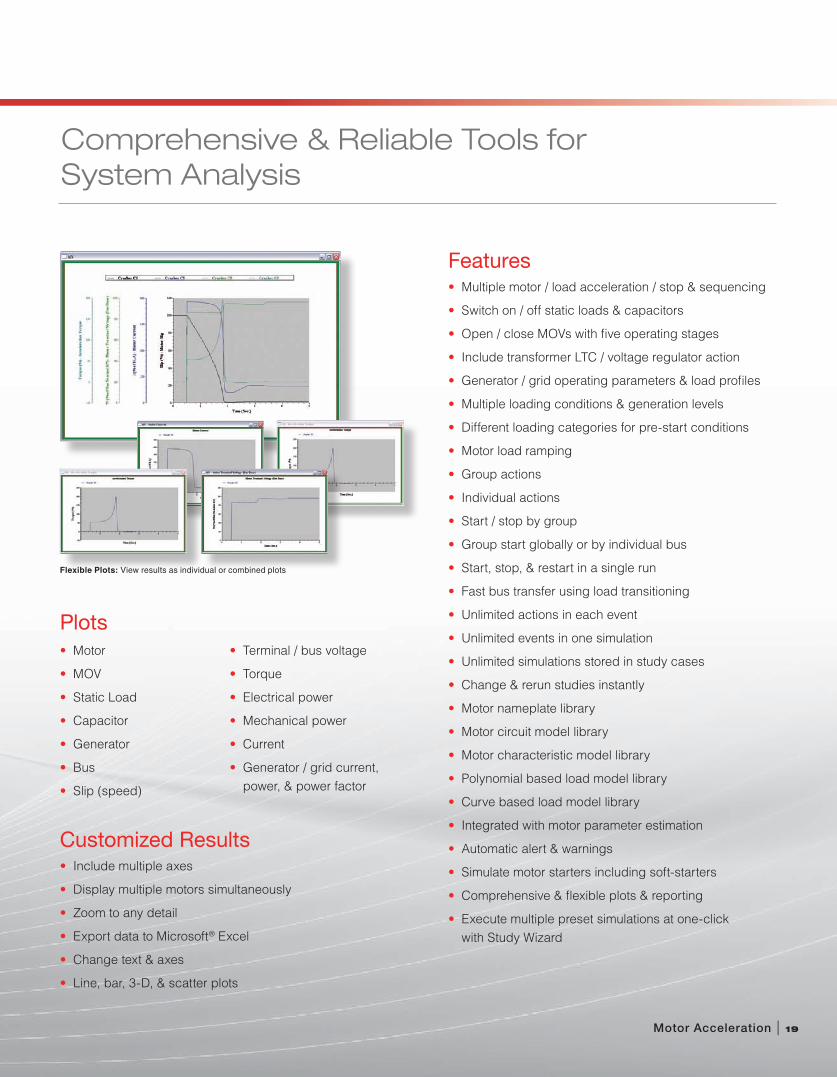
Comprehensive & Reliable Tools for System Analysis
Features• Multiple motor / load acceleration / stop & sequencing
• Switch on / off static loads & capacitors
• Open / close MOVs with five operating stages
• Include transformer LTC / voltage regulator action
• Generator / grid operating parameters & load profiles
• Multiple loading conditions & generation levels
• Different loading categories for pre-start conditions
• Motor load ramping
• Group actions
• Individual actions
• Start / stop by group
• Group start globally or by individual bus
• Start, stop, & restart in a single run
• Fast bus transfer using load transitioning
• Unlimited actions in each event
• Unlimited events in one simulation
• Unlimited simulations stored in study cases
• Change & rerun studies instantly
• Motor nameplate library
• Motor circuit model library
• Motor characteristic model library
• Polynomial based load model library
• Curve based load model library
• Integrated with motor parameter estimation
• Automatic alert & warnings
• Simulate motor starters including soft-starters
• Comprehensive & flexible plots & reporting
• Execute multiple preset simulations at one-click with Study Wizard
Motor Acceleration | 19
Plots• Motor
• MOV
• Static Load
• Capacitor
• Generator
• Bus
• Slip (speed)
• Terminal / bus voltage
• Torque
• Electrical power
• Mechanical power
• Current
• Generator / grid current, power, & power factor
Flexible Plots: View results as individual or combined plots
Customized Results• Include multiple axes
• Display multiple motors simultaneously
• Zoom to any detail
• Export data to Microsoft® Excel
• Change text & axes
• Line, bar, 3-D, & scatter plots

| 17 Goodyear, Suite 100 | Irvine, CA 92618 | T 800.477.ETAP | T 949.462.0100 | F 949.462.0200 | [email protected]
etap.com
© 2008 Operation Technology, Inc. All rights reserved. Certain names and/or logos used in this document may constitute trademarks, service marks, or trade names of Operation Technology, Inc. Other brand and product names are trademarks of their respective holders.
ISO 9001:2000
10 CFR 50 Appendix B
10 CFR 21
ANSI/ASME N45.2
ASME NQA-1
ANSI/IEEE 730.1
CAN/CSA-Q396.1.2
ANSI N45.22
Quality Assurance Commitment ETAP is Verified and Validated (V&V) against field results, real system measurements, established programs, and hand calculations to ensure its technical accuracy. Each release of ETAP undergoes a complete V&V process using thousands of test cases for each and every calculation module. ETAP Quality Assurance program is specifically dedicated to meeting the requirements of:
OperatiOn technOlOgy, inc.


