22
Network Configuration Example Configuring BGP Route Reflectors Release NCE0044 Modified: 2016-11-08 Copyright © 2017, Juniper Networks, Inc.
Network Configuration Example
Configuring BGP Route Reflectors
Release
NCE0044
Modified: 2016-11-08
Copyright © 2017, Juniper Networks, Inc.
Juniper Networks, Inc.1133 InnovationWaySunnyvale, California 94089USA408-745-2000www.juniper.net
Copyright © 2017, Juniper Networks, Inc. All rights reserved.
Juniper Networks, Junos, Steel-Belted Radius, NetScreen, and ScreenOS are registered trademarks of Juniper Networks, Inc. in the UnitedStates and other countries. The Juniper Networks Logo, the Junos logo, and JunosE are trademarks of Juniper Networks, Inc. All othertrademarks, service marks, registered trademarks, or registered service marks are the property of their respective owners.
Juniper Networks assumes no responsibility for any inaccuracies in this document. Juniper Networks reserves the right to change, modify,transfer, or otherwise revise this publication without notice.
Network Configuration Example Configuring BGP Route ReflectorsNCE0044Copyright © 2017, Juniper Networks, Inc.All rights reserved.
The information in this document is current as of the date on the title page.
YEAR 2000 NOTICE
Juniper Networks hardware and software products are Year 2000 compliant. Junos OS has no known time-related limitations through theyear 2038. However, the NTP application is known to have some difficulty in the year 2036.
ENDUSER LICENSE AGREEMENT
The Juniper Networks product that is the subject of this technical documentation consists of (or is intended for use with) Juniper Networkssoftware. Use of such software is subject to the terms and conditions of the End User License Agreement (“EULA”) posted athttp://www.juniper.net/support/eula.html. By downloading, installing or using such software, you agree to the terms and conditions ofthat EULA.
Copyright © 2017, Juniper Networks, Inc.ii
Table of Contents
Chapter 1 Configuring BGP Route Reflectors . . . . . . . . . . . . . . . . . . . . . . . . . . . . . . . . . . . . 5
About This Network Configuration Example . . . . . . . . . . . . . . . . . . . . . . . . . . . . . . . 5
Understanding BGP Route Reflectors . . . . . . . . . . . . . . . . . . . . . . . . . . . . . . . . . . . . 5
Example: Configuring a BGP Route Reflector . . . . . . . . . . . . . . . . . . . . . . . . . . . . . . 7
iiiCopyright © 2017, Juniper Networks, Inc.

Copyright © 2017, Juniper Networks, Inc.iv
Configuring BGP Route Reflectors

CHAPTER 1
Configuring BGP Route Reflectors
• About This Network Configuration Example on page 5
• Understanding BGP Route Reflectors on page 5
• Example: Configuring a BGP Route Reflector on page 7
About This Network Configuration Example
This network configuration example describes how to configure a BGP route reflector
withinanautonomoussystem(AS)andhow it canbeused to improvenetwork scalability
by minimizing the number of advertisements propagated throughout the AS.
Understanding BGP Route Reflectors
Because of the internal BGP (IBGP) full-mesh requirement, most networks use route
reflectors to simplify configuration. The formula to compute the number of sessions
required for a full mesh is v * (v - 1)/2, where v is the number of BGP-enabled devices.
The full-meshmodel does not scale well. Using a route reflector, you group routers into
clusters, which are identified by numeric identifiers unique to the autonomous system
(AS).Within the cluster, youmust configure aBGP session froma single router (the route
reflector) to each internal peer. With this configuration, the IBGP full-mesh requirement
is met.
To use route reflection in an AS, you designate one or more routers as a route
reflector—typically, one per point of presence (POP). Route reflectors have the special
BGP ability to readvertise routes learned from an internal peer to other internal peers.
So rather than requiring all internal peers to be fully meshed with each other, route
reflection requires only that the route reflector be fully meshed with all internal peers.
The route reflector and all of its internal peers form a cluster, as shown in
Figure 1 on page 6.
NOTE: For some JuniperNetworksdevices, youmust haveanAdvancedBGPFeature license installedoneachdevice thatusesa route reflector. For licensedetails, see the Junos OS Initial Configuration Guide for Security Devices.
5Copyright © 2017, Juniper Networks, Inc.

Figure 1: Simple Route Reflector Topology (One Cluster)
Figure 1 on page 6 shows Router RR configured as the route reflector for Cluster 127. The
other routers are designated internal peers within the cluster. BGP routes are advertised
to Router RR by any of the internal peers. RR then readvertises those routes to all other
peers within the cluster.
You can configure multiple clusters and link them by configuring a full mesh of route
reflectors (see Figure 2 on page 6).
Figure 2: Basic Route Reflection (Multiple Clusters)
Figure 2 on page 6 shows Route Reflectors RR 1, RR 2, RR 3, and RR 4 as fully meshed
internal peers. When a router advertises a route to RR 1, RR 1 readvertises the route to
the other route reflectors, which, in turn, readvertise the route to the remaining routers
within the AS. Route reflection allows the route to be propagated throughout the AS
without the scaling problems created by the full mesh requirement.
Copyright © 2017, Juniper Networks, Inc.6
Configuring BGP Route Reflectors

However, as clusters become large, a full mesh with a route reflector becomes difficult
to scale, as does a full mesh between route reflectors. To help offset this problem, you
can group clusters of routers together into clusters of clusters for hierarchical route
reflection (see Figure 3 on page 7).
Figure 3: Hierarchical Route Reflection (Clusters of Clusters)
Figure 3 on page 7 shows RR 2, RR 3, and RR 4 as the route reflectors for Clusters 127,
19, and 45, respectively. Rather than fully mesh those route reflectors, the network
administrator has configured them as part of another cluster (Cluster 6) for which RR 1
is the route reflector. When a router advertises a route to RR 2, RR 2 readvertises the
route to all the routers within its own cluster, and then readvertises the route to RR 1. RR
1 readvertises the route to the routers in its cluster, and those routers propagate the route
down through their clusters.
RelatedDocumentation
Example: Configuring a BGP Route Reflector on page 7•
Example: Configuring a BGP Route Reflector
This example shows how to configure a route reflector.
• Requirements on page 7
• Overview on page 7
• Configuration on page 9
• Verification on page 17
Requirements
No special configuration beyond device initialization is required before you configure this
example.
Overview
Generally, internal BGP (IBGP)-enabled devices need to be fully meshed, because IBGP
does not readvertise updates to other IBGP-enabled devices. The full mesh is a logical
mesh achieved through configuration of multiple neighbor statements on each
7Copyright © 2017, Juniper Networks, Inc.
Chapter 1: Configuring BGP Route Reflectors
IBGP-enabled device. The full mesh is not necessarily a physical full mesh. Maintaining
a full mesh (logical or physical) does not scale well in large deployments.
Figure 4 on page 9 shows an IBGP network with Device A acting as a route reflector.
Device B andDevice C are clients of the route reflector. Device D andDevice E are outside
the cluster, so they are nonclients of the route reflector.
On Device A (the route reflector), youmust form peer relationships with all of the
IBGP-enabled devices by including the neighbor statement for the clients (Device B and
Device C) and the nonclients (Device D and Device E). Youmust also include the cluster
statement and a cluster identifier. The cluster identifier can be any 32-bit value. This
example uses the loopback interface IP address of the route reflector.
On Device B and Device C, the route reflector clients, you only need one neighbor
statement that forms a peer relationship with the route reflector, Device A.
On Device D and Device E, the nonclients, you need a neighbor statement for each
nonclient device (D-to-E and E-to-D). You also need a neighbor statement for the route
reflector (D-to-A and E-to-A). Device D and Device E do not need neighbor statements
for the client devices (Device B and Device C).
TIP: Device D and Device E are considered to be nonclients because theyhave explicitly configured peer relationships with each other. Tomake themRRroute reflector clients, remove the neighbor 192.168.5.5 statement from
theconfigurationonDeviceD, and remove theneighbor 192.168.0.1 statement
from the configuration on Device E.
Copyright © 2017, Juniper Networks, Inc.8
Configuring BGP Route Reflectors

Figure 4: IBGPNetwork Using a Route Reflector
BC
192.168.40.4
192.163.6.4
AS 17
192.168.0.1
192.168.5.5
A
E
D
192.168.6.5
g040
867
Route Reflector
Configuration
CLI QuickConfiguration
To quickly configure this example, copy the following commands, paste them into a text
file, remove any line breaks, change any details necessary to match your network
configuration, and then copy andpaste the commands into theCLI at the [edit]hierarchy
level.
Device A set interfaces fe-0/0/0 unit 1 description to-Bset interfaces fe-0/0/0 unit 1 family inet address 10.10.10.1/30set interfaces fe-0/0/1 unit 3 description to-Dset interfaces fe-0/0/1 unit 3 family inet address 10.10.10.9/30set interfaces lo0 unit 1 family inet address 192.168.6.5/32set protocols bgp group internal-peers type internalset protocols bgp group internal-peers local-address 192.168.6.5set protocols bgp group internal-peers export send-ospfset protocols bgp group internal-peers cluster 192.168.6.5set protocols bgp group internal-peers neighbor 192.163.6.4set protocols bgp group internal-peers neighbor 192.168.40.4set protocols bgp group internal-peers neighbor 192.168.0.1set protocols bgp group internal-peers neighbor 192.168.5.5set protocols ospf area 0.0.0.0 interface lo0.1 passiveset protocols ospf area 0.0.0.0 interface fe-0/0/0.1set protocols ospf area 0.0.0.0 interface fe-0/0/1.3set policy-options policy-statement send-ospf term 2 from protocol ospf
9Copyright © 2017, Juniper Networks, Inc.
Chapter 1: Configuring BGP Route Reflectors

set policy-options policy-statement send-ospf term 2 then acceptset routing-options router-id 192.168.6.5set routing-options autonomous-system 17
Device B set interfaces fe-0/0/0 unit 2 description to-Aset interfaces fe-0/0/0 unit 2 family inet address 10.10.10.2/30set interfaces fe-0/0/1 unit 5 description to-Cset interfaces fe-0/0/1 unit 5 family inet address 10.10.10.5/30set interfaces lo0 unit 2 family inet address 192.163.6.4/32set protocols bgp group internal-peers type internalset protocols bgp group internal-peers local-address 192.163.6.4set protocols bgp group internal-peers export send-ospfset protocols bgp group internal-peers neighbor 192.168.6.5set protocols ospf area 0.0.0.0 interface lo0.2 passiveset protocols ospf area 0.0.0.0 interface fe-0/0/0.2set protocols ospf area 0.0.0.0 interface fe-0/0/1.5set policy-options policy-statement send-ospf term 2 from protocol ospfset policy-options policy-statement send-ospf term 2 then acceptset routing-options router-id 192.163.6.4set routing-options autonomous-system 17
Device C set interfaces fe-0/0/0 unit 6 description to-Bset interfaces fe-0/0/0 unit 6 family inet address 10.10.10.6/30set interfaces lo0 unit 3 family inet address 192.168.40.4/32set protocols bgp group internal-peers type internalset protocols bgp group internal-peers local-address 192.168.40.4set protocols bgp group internal-peers export send-ospfset protocols bgp group internal-peers neighbor 192.168.6.5set protocols ospf area 0.0.0.0 interface lo0.3 passiveset protocols ospf area 0.0.0.0 interface fe-0/0/0.6set policy-options policy-statement send-ospf term 2 from protocol ospfset policy-options policy-statement send-ospf term 2 then acceptset routing-options router-id 192.168.40.4set routing-options autonomous-system 17
Device D set interfaces fe-0/0/0 unit 4 description to-Aset interfaces fe-0/0/0 unit 4 family inet address 10.10.10.10/30set interfaces fe-0/0/1 unit 7 description to-Eset interfaces fe-0/0/1 unit 7 family inet address 10.10.10.13/30set interfaces lo0 unit 4 family inet address 192.168.0.1/32set protocols bgp group internal-peers type internalset protocols bgp group internal-peers local-address 192.168.0.1set protocols bgp group internal-peers export send-ospfset protocols bgp group internal-peers neighbor 192.168.6.5set protocols bgp group internal-peers neighbor 192.168.5.5set protocols ospf area 0.0.0.0 interface lo0.4 passiveset protocols ospf area 0.0.0.0 interface fe-0/0/0.4set protocols ospf area 0.0.0.0 interface fe-0/0/1.7set policy-options policy-statement send-ospf term 2 from protocol ospfset policy-options policy-statement send-ospf term 2 then acceptset routing-options router-id 192.168.0.1set routing-options autonomous-system 17
Device E set interfaces fe-0/0/0 unit 8 description to-Dset interfaces fe-0/0/0 unit 8 family inet address 10.10.10.14/30
Copyright © 2017, Juniper Networks, Inc.10
Configuring BGP Route Reflectors

set interfaces lo0 unit 5 family inet address 192.168.5.5/32set protocols bgp group internal-peers type internalset protocols bgp group internal-peers local-address 192.168.5.5set protocols bgp group internal-peers export send-ospfset protocols bgp group internal-peers neighbor 192.168.0.1set protocols bgp group internal-peers neighbor 192.168.6.5set protocols ospf area 0.0.0.0 interface lo0.5 passiveset protocols ospf area 0.0.0.0 interface fe-0/0/0.8set policy-options policy-statement send-ospf term 2 from protocol ospfset policy-options policy-statement send-ospf term 2 then acceptset routing-options router-id 192.168.5.5set routing-options autonomous-system 17
Configuring the Route Reflector
Step-by-StepProcedure
The following example requires you to navigate various levels in the configuration
hierarchy. For informationaboutnavigating theCLI, seeUsing theCLI Editor inConfiguration
Mode in the CLI User Guide.
To configure IBGP in the network using Juniper Networks Device A as a route reflector:
1. Configure the interfaces.
[edit interfaces]user@A# set fe-0/0/0 unit 1 description to-Buser@A# set fe-0/0/0 unit 1 family inet address 10.10.10.1/30user@A# set fe-0/0/1 unit 3 description to-Duser@A# set fe-0/0/1 unit 3 family inet address 10.10.10.9/30user@A# set lo0 unit 1 family inet address 192.168.6.5/32
2. Configure BGP, including the cluster identifier and neighbor relationships with all
IBGP-enabled devices in the autonomous system (AS).
Also apply the policy that redistributes OSPF routes into BGP.
[edit protocols bgp group internal-peers]user@A# set type internaluser@A# set local-address 192.168.6.5user@A# set export send-ospfuser@A# set cluster 192.168.6.5user@A# set neighbor 192.163.6.4user@A# set neighbor 192.168.40.4user@A# set neighbor 192.168.0.1user@A# set neighbor 192.168.5.5
3. Configure static routing or an interior gateway protocol (IGP).
This example uses OSPF.
[edit protocols ospf area 0.0.0.0]user@A# set interface lo0.1 passiveuser@A# set interface fe-0/0/0.1user@A# set interface fe-0/0/1.3
4. Configure the policy that redistributes OSPF routes into BGP.
[edit policy-options policy-statement send-ospf term 2]user@A# set from protocol ospf
11Copyright © 2017, Juniper Networks, Inc.
Chapter 1: Configuring BGP Route Reflectors

user@A# set then accept
5. Configure the router ID and the autonomous system (AS) number.
[edit routing-options]user@A# set router-id 192.168.6.5user@A# set autonomous-system 17
Results From configuration mode, confirm your configuration by entering the show interfaces,
showprotocols, showpolicy-options, and show routing-options commands. If the output
does not display the intended configuration, repeat the instructions in this example to
correct the configuration.
user@A# show interfacesfe-0/0/0 {unit 1 {description to-B;family inet {address 10.10.10.1/30;
}}
}fe-0/0/1 {unit 3 {description to-D;family inet {address 10.10.10.9/30;
}}
}lo0 {unit 1 {family inet {address 192.168.6.5/32;
}}
}
user@A# show protocolsbgp {group internal-peers {type internal;local-address 192.168.6.5;export send-ospf;cluster 192.168.6.5;neighbor 192.163.6.4;neighbor 192.168.40.4;neighbor 192.168.0.1;neighbor 192.168.5.5;
}}ospf {area 0.0.0.0 {interface lo0.1 {passive;
}
Copyright © 2017, Juniper Networks, Inc.12
Configuring BGP Route Reflectors

interface fe-0/0/0.1;interface fe-0/0/1.3;
}}
user@A# show policy-optionspolicy-statement send-ospf {term 2 {from protocol ospf;then accept;
}}
user@A# show routing-optionsrouter-id 192.168.6.5;autonomous-system 17;
If you are done configuring the device, enter commit from configuration mode.
NOTE: Repeat these steps for each nonclient BGP peer within the clusterthat you are configuring, if the other nonclient devices are from JuniperNetworks. Otherwise, consult the device’s documentation for instructions.
Configuring Client Peers
Step-by-StepProcedure
The following example requires you to navigate various levels in the configuration
hierarchy. For informationaboutnavigating theCLI, seeUsing theCLI Editor inConfiguration
Mode in the CLI User Guide.
To configure client peers:
1. Configure the interfaces.
[edit interfaces]user@B# set fe-0/0/0 unit 2 description to-Auser@B# set fe-0/0/0 unit 2 family inet address 10.10.10.2/30user@B# set fe-0/0/1 unit 5 description to-Cuser@B# set fe-0/0/1 unit 5 family inet address 10.10.10.5/30user@B# set lo0 unit 2 family inet address 192.163.6.4/32
2. Configure the BGP neighbor relationship with the route reflector.
Also apply the policy that redistributes OSPF routes into BGP.
[edit protocols bgp group internal-peers]user@B# set type internaluser@B# set local-address 192.163.6.4user@B# set export send-ospfuser@B# set neighbor 192.168.6.5
3. Configure OSPF.
[edit protocols ospf area 0.0.0.0]user@B# set interface lo0.2 passiveuser@B# set interface fe-0/0/0.2
13Copyright © 2017, Juniper Networks, Inc.
Chapter 1: Configuring BGP Route Reflectors

user@B# set interface fe-0/0/1.5
4. Configure the policy that redistributes OSPF routes into BGP.
[edit policy-options policy-statement send-ospf term 2]user@B# set from protocol ospfuser@B# set then accept
5. Configure the router ID and the AS number.
[edit routing-options]user@B# set router-id 192.163.6.4user@B# set autonomous-system 17
Results From configuration mode, confirm your configuration by entering the show interfaces,
showprotocols, showpolicy-options, and show routing-options commands. If the output
does not display the intended configuration, repeat the instructions in this example to
correct the configuration.
user@B# show interfacesfe-0/0/0 {unit 2 {description to-A;family inet {address 10.10.10.2/30;
}}
}fe-0/0/1 {unit 5 {description to-C;family inet {address 10.10.10.5/30;
}}
}lo0 {unit 2 {family inet {address 192.163.6.4/32;
}}
}
user@B# show protocolsbgp {group internal-peers {type internal;local-address 192.163.6.4;export send-ospf;neighbor 192.168.6.5;
}}ospf {area 0.0.0.0 {interface lo0.2 {passive;
Copyright © 2017, Juniper Networks, Inc.14
Configuring BGP Route Reflectors

}interface fe-0/0/0.2;interface fe-0/0/1.5;
}}
user@B# show policy-optionspolicy-statement send-ospf {term 2 {from protocol ospf;then accept;
}}
user@B# show routing-optionsrouter-id 192.163.6.4;autonomous-system 17;
If you are done configuring the device, enter commit from configuration mode.
NOTE: Repeat these steps for each client BGP peer within the cluster thatyou are configuring if the other client devices are from Juniper Networks.Otherwise, consult the device’s documentation for instructions.
Configuring Nonclient Peers
Step-by-StepProcedure
The following example requires you to navigate various levels in the configuration
hierarchy. For informationaboutnavigating theCLI, seeUsing theCLI Editor inConfiguration
Mode in the CLI User Guide.
To configure nonclient peers:
1. Configure the interfaces.
[edit interfaces]user@D# set fe-0/0/0 unit 4 description to-Auser@D# set fe-0/0/0 unit 4 family inet address 10.10.10.10/30user@D# set fe-0/0/1 unit 7 description to-Euser@D# set fe-0/0/1 unit 7 family inet address 10.10.10.13/30user@D# set lo0 unit 4 family inet address 192.168.0.1/32
2. Configure the BGP neighbor relationships with the RRroute reflector and with the
other nonclient peers.
Also apply the policy that redistributes OSPF routes into BGP.
[edit protocols bgp group internal-peers]user@D# set type internaluser@D# set local-address 192.168.0.1user@D# set export send-ospfuser@D# set neighbor 192.168.6.5user@D# set neighbor 192.168.5.5
3. Configure OSPF.
15Copyright © 2017, Juniper Networks, Inc.
Chapter 1: Configuring BGP Route Reflectors

[edit protocols ospf area 0.0.0.0]user@D# set interface lo0.4 passiveuser@D# set interface fe-0/0/0.4user@D# set interface fe-0/0/1.7
4. Configure the policy that redistributes OSPF routes into BGP.
[edit policy-options policy-statement send-ospf term 2]user@D# set from protocol ospfuser@D# set then accept
5. Configure the router ID and the AS number.
[edit routing-options]user@D# set router-id 192.168.0.1user@D# set autonomous-system 17
Results From configuration mode, confirm your configuration by entering the show interfaces,
showprotocols, showpolicy-options, and show routing-options commands. If the output
does not display the intended configuration, repeat the instructions in this example to
correct the configuration.
user@D# show interfacesfe-0/0/0 {unit 4 {description to-A;family inet {address 10.10.10.10/30;
}}
}fe-0/0/1 {unit 7 {description to-E;family inet {address 10.10.10.13/30;
}}
}lo0 {unit 4 {family inet {address 192.168.0.1/32;
}}
}
user@D# show protocolsbgp {group internal-peers {type internal;local-address 192.168.0.1;export send-ospf;neighbor 192.168.6.5;neighbor 192.168.5.5;
}}
Copyright © 2017, Juniper Networks, Inc.16
Configuring BGP Route Reflectors

ospf {area 0.0.0.0 {interface lo0.4 {passive;
}interface fe-0/0/0.4;interface fe-0/0/1.7;
}}
user@D# show policy-optionspolicy-statement send-ospf {term 2 {from protocol ospf;then accept;
}}
user@D# show routing-optionsrouter-id 192.168.0.1;autonomous-system 17;
If you are done configuring the device, enter commit from configuration mode.
NOTE: Repeat these steps for each nonclient BGP peer within the clusterthat you are configuring if the other nonclient devices are from JuniperNetworks. Otherwise, consult the device’s documentation for instructions.
Verification
Confirm that the configuration is working properly.
• Verifying BGP Neighbors on page 17
• Verifying BGP Groups on page 20
• Verifying BGP Summary Information on page 20
• Verifying Routing Table Information on page 21
Verifying BGPNeighbors
Purpose Verify thatBGP is runningonconfigured interfacesand that theBGPsession is established
for each neighbor address.
Action From operational mode, enter the show bgp neighbor command.
user@A> show bgp neighborPeer: 192.163.6.4+179 AS 17 Local: 192.168.6.5+62857 AS 17 Type: Internal State: Established (route reflector client)Flags: <Sync> Last State: OpenConfirm Last Event: RecvKeepAlive Last Error: None Export: [ send-ospf ] Options: <Preference LocalAddress Cluster Refresh> Local Address: 192.168.6.5 Holdtime: 90 Preference: 170
17Copyright © 2017, Juniper Networks, Inc.
Chapter 1: Configuring BGP Route Reflectors

Number of flaps: 0 Peer ID: 192.163.6.4 Local ID: 192.168.6.5 Active Holdtime: 90 Keepalive Interval: 30 Peer index: 0 BFD: disabled, down NLRI for restart configured on peer: inet-unicast NLRI advertised by peer: inet-unicast NLRI for this session: inet-unicast Peer supports Refresh capability (2) Restart time configured on the peer: 120 Stale routes from peer are kept for: 300 Restart time requested by this peer: 120 NLRI that peer supports restart for: inet-unicast NLRI that restart is negotiated for: inet-unicast NLRI of received end-of-rib markers: inet-unicast NLRI of all end-of-rib markers sent: inet-unicast Peer supports 4 byte AS extension (peer-as 17) Peer does not support Addpath Table inet.0 Bit: 10000 RIB State: BGP restart is complete Send state: in sync Active prefixes: 0 Received prefixes: 6 Accepted prefixes: 1 Suppressed due to damping: 0 Advertised prefixes: 6 Last traffic (seconds): Received 5 Sent 3 Checked 19 Input messages: Total 2961 Updates 7 Refreshes 0 Octets 56480 Output messages: Total 2945 Updates 6 Refreshes 0 Octets 56235 Output Queue[0]: 0
Peer: 192.168.0.1+179 AS 17 Local: 192.168.6.5+60068 AS 17 Type: Internal State: Established (route reflector client)Flags: <Sync> Last State: OpenConfirm Last Event: RecvKeepAlive Last Error: None Export: [ send-ospf ] Options: <Preference LocalAddress Cluster Refresh> Local Address: 192.168.6.5 Holdtime: 90 Preference: 170 Number of flaps: 0 Peer ID: 192.168.0.1 Local ID: 192.168.6.5 Active Holdtime: 90 Keepalive Interval: 30 Peer index: 3 BFD: disabled, down NLRI for restart configured on peer: inet-unicast NLRI advertised by peer: inet-unicast NLRI for this session: inet-unicast Peer supports Refresh capability (2) Restart time configured on the peer: 120 Stale routes from peer are kept for: 300 Restart time requested by this peer: 120 NLRI that peer supports restart for: inet-unicast NLRI that restart is negotiated for: inet-unicast NLRI of received end-of-rib markers: inet-unicast NLRI of all end-of-rib markers sent: inet-unicast Peer supports 4 byte AS extension (peer-as 17) Peer does not support Addpath Table inet.0 Bit: 10000 RIB State: BGP restart is complete Send state: in sync Active prefixes: 0 Received prefixes: 6 Accepted prefixes: 1 Suppressed due to damping: 0
Copyright © 2017, Juniper Networks, Inc.18
Configuring BGP Route Reflectors

Advertised prefixes: 6 Last traffic (seconds): Received 18 Sent 20 Checked 12 Input messages: Total 15 Updates 5 Refreshes 0 Octets 447 Output messages: Total 554 Updates 4 Refreshes 0 Octets 32307 Output Queue[0]: 0
Peer: 192.168.5.5+57458 AS 17 Local: 192.168.6.5+179 AS 17 Type: Internal State: Established (route reflector client)Flags: <Sync> Last State: OpenConfirm Last Event: RecvKeepAlive Last Error: None Export: [ send-ospf ] Options: <Preference LocalAddress Cluster Refresh> Local Address: 192.168.6.5 Holdtime: 90 Preference: 170 Number of flaps: 0 Peer ID: 192.168.5.5 Local ID: 192.168.6.5 Active Holdtime: 90 Keepalive Interval: 30 Peer index: 2 BFD: disabled, down NLRI for restart configured on peer: inet-unicast NLRI advertised by peer: inet-unicast NLRI for this session: inet-unicast Peer supports Refresh capability (2) Restart time configured on the peer: 120 Stale routes from peer are kept for: 300 Restart time requested by this peer: 120 NLRI that peer supports restart for: inet-unicast NLRI that restart is negotiated for: inet-unicast NLRI of received end-of-rib markers: inet-unicast NLRI of all end-of-rib markers sent: inet-unicast Peer supports 4 byte AS extension (peer-as 17) Peer does not support Addpath Table inet.0 Bit: 10000 RIB State: BGP restart is complete Send state: in sync Active prefixes: 0 Received prefixes: 7 Accepted prefixes: 7 Suppressed due to damping: 0 Advertised prefixes: 6 Last traffic (seconds): Received 17 Sent 3 Checked 9 Input messages: Total 2967 Updates 7 Refreshes 0 Octets 56629 Output messages: Total 2943 Updates 6 Refreshes 0 Octets 56197 Output Queue[0]: 0
Peer: 192.168.40.4+53990 AS 17 Local: 192.168.6.5+179 AS 17 Type: Internal State: Established (route reflector client)Flags: <Sync> Last State: OpenConfirm Last Event: RecvKeepAlive Last Error: None Export: [ send-ospf ] Options: <Preference LocalAddress Cluster Refresh> Local Address: 192.168.6.5 Holdtime: 90 Preference: 170 Number of flaps: 0 Peer ID: 192.168.40.4 Local ID: 192.168.6.5 Active Holdtime: 90 Keepalive Interval: 30 Peer index: 1 BFD: disabled, down NLRI for restart configured on peer: inet-unicast NLRI advertised by peer: inet-unicast NLRI for this session: inet-unicast Peer supports Refresh capability (2) Restart time configured on the peer: 120 Stale routes from peer are kept for: 300 Restart time requested by this peer: 120
19Copyright © 2017, Juniper Networks, Inc.
Chapter 1: Configuring BGP Route Reflectors
NLRI that peer supports restart for: inet-unicast NLRI that restart is negotiated for: inet-unicast NLRI of received end-of-rib markers: inet-unicast NLRI of all end-of-rib markers sent: inet-unicast Peer supports 4 byte AS extension (peer-as 17) Peer does not support Addpath Table inet.0 Bit: 10000 RIB State: BGP restart is complete Send state: in sync Active prefixes: 0 Received prefixes: 7 Accepted prefixes: 7 Suppressed due to damping: 0 Advertised prefixes: 6 Last traffic (seconds): Received 5 Sent 23 Checked 52 Input messages: Total 2960 Updates 7 Refreshes 0 Octets 56496 Output messages: Total 2943 Updates 6 Refreshes 0 Octets 56197 Output Queue[0]: 0
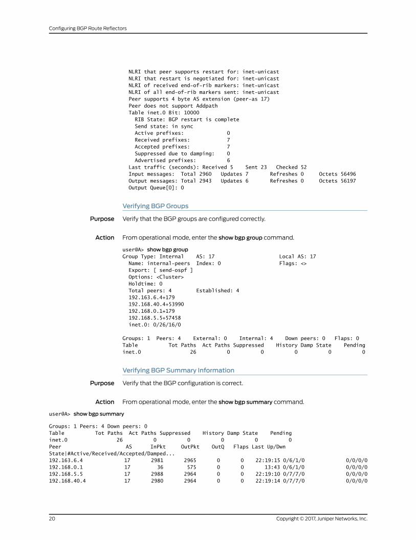
Verifying BGPGroups
Purpose Verify that the BGP groups are configured correctly.
Action From operational mode, enter the show bgp group command.
user@A> show bgp groupGroup Type: Internal AS: 17 Local AS: 17 Name: internal-peers Index: 0 Flags: <> Export: [ send-ospf ] Options: <Cluster> Holdtime: 0 Total peers: 4 Established: 4 192.163.6.4+179 192.168.40.4+53990 192.168.0.1+179 192.168.5.5+57458 inet.0: 0/26/16/0
Groups: 1 Peers: 4 External: 0 Internal: 4 Down peers: 0 Flaps: 0Table Tot Paths Act Paths Suppressed History Damp State Pendinginet.0 26 0 0 0 0 0
Verifying BGP Summary Information
Purpose Verify that the BGP configuration is correct.
Action From operational mode, enter the show bgp summary command.
user@A> show bgp summary
Groups: 1 Peers: 4 Down peers: 0Table Tot Paths Act Paths Suppressed History Damp State Pendinginet.0 26 0 0 0 0 0Peer AS InPkt OutPkt OutQ Flaps Last Up/Dwn State|#Active/Received/Accepted/Damped...192.163.6.4 17 2981 2965 0 0 22:19:15 0/6/1/0 0/0/0/0192.168.0.1 17 36 575 0 0 13:43 0/6/1/0 0/0/0/0192.168.5.5 17 2988 2964 0 0 22:19:10 0/7/7/0 0/0/0/0192.168.40.4 17 2980 2964 0 0 22:19:14 0/7/7/0 0/0/0/0
Copyright © 2017, Juniper Networks, Inc.20
Configuring BGP Route Reflectors

Verifying Routing Table Information
Purpose Verify that the routing table contains the IBGP routes.
Action From operational mode, enter the show route command.
user@A> show routeinet.0: 12 destinations, 38 routes (12 active, 0 holddown, 10 hidden)+ = Active Route, - = Last Active, * = Both
10.10.10.0/30 *[Direct/0] 22:22:03 > via fe-0/0/0.1 [BGP/170] 22:20:55, MED 2, localpref 100, from 192.168.40.4 AS path: I > to 10.10.10.2 via fe-0/0/0.1 [BGP/170] 22:20:51, MED 3, localpref 100, from 192.168.5.5 AS path: I > to 10.10.10.10 via fe-0/0/1.310.10.10.1/32 *[Local/0] 22:22:03 Local via fe-0/0/0.110.10.10.4/30 *[OSPF/10] 22:21:13, metric 2 > to 10.10.10.2 via fe-0/0/0.1 [BGP/170] 22:20:51, MED 4, localpref 100, from 192.168.5.5 AS path: I > to 10.10.10.10 via fe-0/0/1.310.10.10.8/30 *[Direct/0] 22:22:03 > via fe-0/0/1.3 [BGP/170] 22:20:51, MED 2, localpref 100, from 192.168.5.5 AS path: I > to 10.10.10.10 via fe-0/0/1.3 [BGP/170] 22:20:55, MED 3, localpref 100, from 192.168.40.4 AS path: I > to 10.10.10.2 via fe-0/0/0.110.10.10.9/32 *[Local/0] 22:22:03 Local via fe-0/0/1.310.10.10.12/30 *[OSPF/10] 22:21:08, metric 2 > to 10.10.10.10 via fe-0/0/1.3 [BGP/170] 22:20:55, MED 4, localpref 100, from 192.168.40.4 AS path: I > to 10.10.10.2 via fe-0/0/0.1192.163.6.4/32 *[OSPF/10] 22:21:13, metric 1 > to 10.10.10.2 via fe-0/0/0.1 [BGP/170] 22:20:55, MED 1, localpref 100, from 192.168.40.4 AS path: I > to 10.10.10.2 via fe-0/0/0.1 [BGP/170] 22:20:51, MED 3, localpref 100, from 192.168.5.5 AS path: I > to 10.10.10.10 via fe-0/0/1.3192.168.0.1/32 *[OSPF/10] 22:21:08, metric 1 > to 10.10.10.10 via fe-0/0/1.3 [BGP/170] 22:20:51, MED 1, localpref 100, from 192.168.5.5 AS path: I > to 10.10.10.10 via fe-0/0/1.3 [BGP/170] 22:20:55, MED 3, localpref 100, from 192.168.40.4 AS path: I > to 10.10.10.2 via fe-0/0/0.1192.168.5.5/32 *[OSPF/10] 22:21:08, metric 2 > to 10.10.10.10 via fe-0/0/1.3 [BGP/170] 00:15:24, MED 1, localpref 100, from 192.168.0.1 AS path: I
21Copyright © 2017, Juniper Networks, Inc.
Chapter 1: Configuring BGP Route Reflectors

> to 10.10.10.10 via fe-0/0/1.3 [BGP/170] 22:20:55, MED 4, localpref 100, from 192.168.40.4 AS path: I > to 10.10.10.2 via fe-0/0/0.1192.168.6.5/32 *[Direct/0] 22:22:04 > via lo0.1 [BGP/170] 22:20:51, MED 2, localpref 100, from 192.168.5.5 AS path: I > to 10.10.10.10 via fe-0/0/1.3 [BGP/170] 22:20:55, MED 2, localpref 100, from 192.168.40.4 AS path: I > to 10.10.10.2 via fe-0/0/0.1192.168.40.4/32 *[OSPF/10] 22:21:13, metric 2 > to 10.10.10.2 via fe-0/0/0.1 [BGP/170] 22:20:55, MED 1, localpref 100, from 192.163.6.4 AS path: I > to 10.10.10.2 via fe-0/0/0.1 [BGP/170] 22:20:51, MED 4, localpref 100, from 192.168.5.5 AS path: I > to 10.10.10.10 via fe-0/0/1.3224.0.0.5/32 *[OSPF/10] 22:22:07, metric 1 MultiRecv
RelatedDocumentation
• Understanding BGP Route Reflectors on page 5
Copyright © 2017, Juniper Networks, Inc.22
Configuring BGP Route Reflectors


