44
Network Configuration Management Nick Feamster CS 6250: Computer Networking Fall 2011 (Some slides on configuration complexity from Prof. Aditya Akella)
| Date post: | 21-Dec-2015 |
| Category: |
Documents |
| View: | 225 times |
| Download: | 3 times |
Network Configuration Management
Nick FeamsterCS 6250: Computer Networking
Fall 2011
(Some slides on configuration complexity from Prof. Aditya Akella)

The Case for Management
• Typical problem–Remote user arrives at regional office and experiences slow or no response from corporate web server
• Where do you begin?–Where is the problem?–What is the problem?–What is the solution?
• Without proper network management, these questions are difficult to answer
Corp Network
Regional Offices
WWW Servers
Remote User

Corp Network
Regional Offices
WWW Servers
Remote User
The Case for Management
• With proper management tools and procedures in place, you may already have the answer
• Consider some possibilities What configuration changes were
made overnight? Have you received a device fault
notification indicating the issue? Have you detected a security
breach? Has your performance baseline
predicted this behavior on an increasingly congested network link?

• An accurate database of your network’s topology, configuration, and performance
• A solid understanding of the protocols and models used in communication between your management server and the managed devices
• Methods and tools that allow you to interpret and act upon gathered information
Response Times High Availability
Predictability
Security
Problem Solving

5
Network Configuration
6
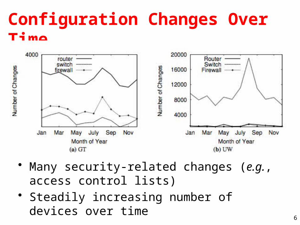
Configuration Changes Over Time
• Many security-related changes (e.g., access control lists)
• Steadily increasing number of devices over time
7
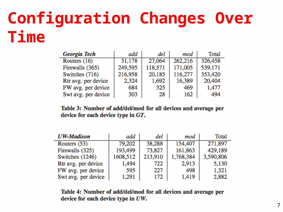
Configuration Changes Over Time

8
Modern Networks are Complex
• Intricate logical and physical topologies
• Diverse network devices– Operating at different layers– Different command sets, detailed
configuration
• Operators constantly tweak network configurations– New admin policies– Quick-fixes in response to crises
• Diverse goals– E.g. QOS, security, routing,
resilience
Complex configuration
9
Interface vlan901
ip address 10.1.1.2 255.0.0.0
ip access-group 9 out
!Router ospf 1router-id 10.1.2.23network 10.0.0.0 0.255.255.255
!
access-list 9 10.1.0.0 0.0.255.255
Interface vlan901
ip address 10.1.1.5 255.0.0.0
ip access-group 9 out
!Router ospf 1router-id 10.1.2.23network 10.0.0.0 0.255.255.255
!
access-list 9 10.1.0.0 0.0.255.255
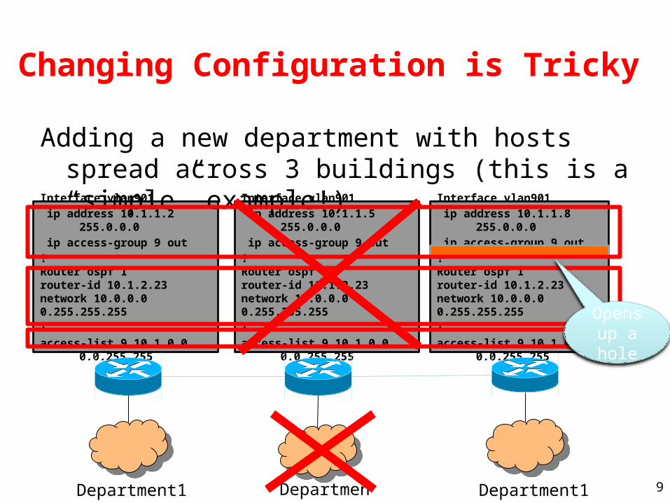
Changing Configuration is Tricky
Adding a new department with hosts spread across 3 buildings (this is a “simple” example!)
Interface vlan901
ip address 10.1.1.8 255.0.0.0
ip access-group 9 out
!Router ospf 1router-id 10.1.2.23network 10.0.0.0 0.255.255.255
!
access-list 9 10.1.0.0 0.0.255.255
Department1Department1 Department1
Opens up a hole

10
Getting a Grip on Complexity
• Complexity misconfiguration, outages
• Can’t measure complexity today – Ability to predict difficulty of future changes
• Benchmarks in architecture, DB, software engineering have guided system design
• Metrics essential for designing manageable networks
• No systematic way to mitigate or control complexity
• Quick fix may complicate future changes– Troubleshooting, upgrades harder over
time• Hard to select the simplest from
alternatesOptions for making a change
or for ground-up design
Com
plex
ity
of n
/w d
esig
n
#1 #2 #3

Measuring and Mitigating Complexity
• Metrics for layer-3 static configuration [NSDI 2009]– Succinctly describe complexity
• Align with operator mental models, best common practices
– Predictive of difficulty• Useful to pick among alternates
– Empiricial study and operator tests for 7 networks
• Network-specific and common
• Network redesign (L3 config)– Discovering and representing
policies [IMC 2009]• Invariants in network redesign
– Automatic network design simplification [Ongoing work]
• Metrics guide design exploration
Options for making a changeor for ground-up design
Co
mp
lexi
ty
of
n/w
de
sig
n
#1 #2 #3
Many routing processwith minor differences
Few consolidatedrouting process
(2) Ground-up simplification
(1) Useful to pick among alternates
Metrics

12
Services
• VPN: Each customer gets a private IP network, allowing sites to exchange traffic among themselves
• VPLS: Private Ethernet (layer-2) network• DDoS Protection: Direct attack traffic to a
“scrubbing farm”• Virtual Wire: Point-to-point VPLS network• VoIP: Voice over IP

13
MPLS Overview
• Main idea: Virtual circuit– Packets forwarded based only on circuit identifier
Destination
Source 1
Source 2
Router can forward traffic to the same destination on different interfaces/paths.

14
Circuit Abstraction: Label Swapping
• Label-switched paths (LSPs): Paths are “named” by the label at the path’s entry point
• At each hop, label determines:– Outgoing interface– New label to attach
• Label distribution protocol: responsible for disseminating signalling information
A 12
3
A 2 D
Tag Out New
D
15
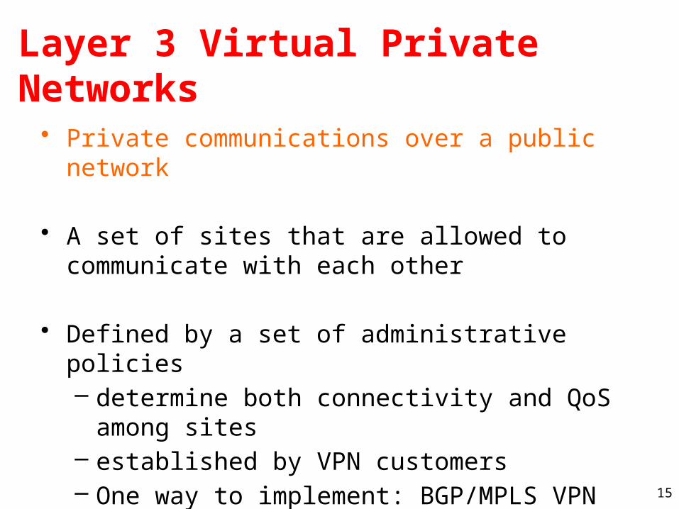
Layer 3 Virtual Private Networks
• Private communications over a public network
• A set of sites that are allowed to communicate with each other
• Defined by a set of administrative policies– determine both connectivity and QoS among
sites– established by VPN customers– One way to implement: BGP/MPLS VPN
mechanisms (RFC 2547)

16
Building Private Networks
• Separate physical network– Good security properties– Expensive!
• Secure VPNs– Encryption of entire network stack between endpoints
• Layer 2 Tunneling Protocol (L2TP)– “PPP over IP”– No encryption
• Layer 3 VPNs
Privacy and interconnectivity (not confidentiality, integrity, etc.)

17
Layer 2 vs. Layer 3 VPNs
• Layer 2 VPNs can carry traffic for many different protocols, whereas Layer 3 is “IP only”
• More complicated to provision a Layer 2 VPN
• Layer 3 VPNs: potentially more flexibility, fewer configuration headaches

18
Layer 3 BGP/MPLS VPNs
• Isolation: Multiple logical networks over a single, shared physical infrastructure
• Tunneling: Keeping routes out of the core
VPN A/Site 1
VPN A/Site 2
VPN A/Site 3
VPN B/Site 2
VPN B/Site 1
VPN B/Site 3
CEA1
CEB3
CEA3
CEB2
CEA2CE1B1
CE2B1
PE1
PE2
PE3
P1
P2
P3
10.1/16
10.2/16
10.3/16
10.1/16
10.2/16
10.4/16
BGP to exchange routes
MPLS to forward traffic

19
High-Level Overview of Operation
• IP packets arrive at PE
• Destination IP address is looked up in forwarding table
• Datagram sent to customer’s network using tunneling (i.e., an MPLS label-switched path)

20
BGP/MPLS VPN key components
• Forwarding in the core: MPLS
• Distributing routes between PEs: BGP
• Isolation: Keeping different VPNs from routing traffic over one another– Constrained distribution of routing information– Multiple “virtual” forwarding tables
• Unique addresses: VPN-IP4 Address extension

21
Virtual Routing and Forwarding
• Separate tables per customer at each router
10.0.1.0/24RD: Green
10.0.1.0/24RD: Blue
10.0.1.0/24
10.0.1.0/24
Customer 1
Customer 2
Customer 1
Customer 2
22
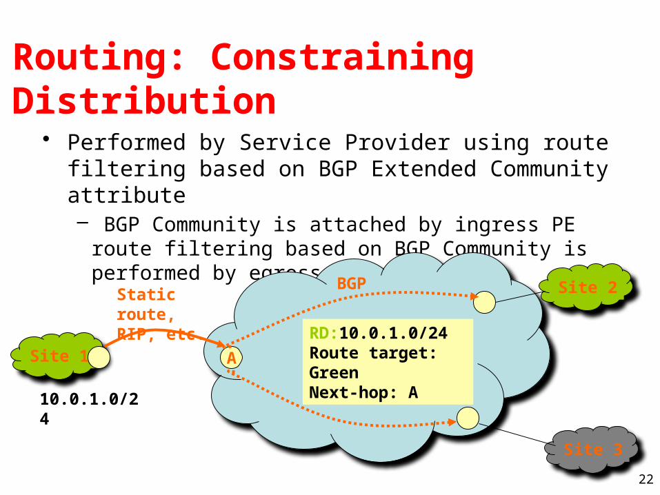
Routing: Constraining Distribution
• Performed by Service Provider using route filtering based on BGP Extended Community attribute– BGP Community is attached by ingress PE route filtering
based on BGP Community is performed by egress PE
Site 1
Site 2
Site 3
Static route, RIP, etc.
RD:10.0.1.0/24Route target: GreenNext-hop: A
A
10.0.1.0/24
BGP
23
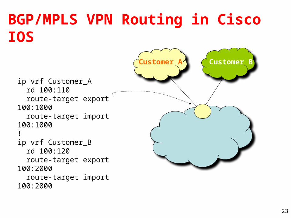
BGP/MPLS VPN Routing in Cisco IOS
ip vrf Customer_A rd 100:110 route-target export 100:1000 route-target import 100:1000 ! ip vrf Customer_B rd 100:120 route-target export 100:2000 route-target import 100:2000
Customer A Customer B

24
Forwarding• PE and P routers have BGP next-hop reachability
through the backbone IGP
• Labels are distributed through LDP (hop-by-hop) corresponding to BGP Next-Hops
• Two-Label Stack is used for packet forwarding• Top label indicates Next-Hop (interior label)• Second level label indicates outgoing interface or
VRF (exterior label)
IP DatagramLabel2
Label1
Layer 2 Header
Corresponds to LSP ofBGP next-hop (PE)
Corresponds to VRF/interface at exit

25
Forwarding in BGP/MPLS VPNs
• Step 1: Packet arrives at incoming interface– Site VRF determines BGP next-hop and Label #2
IP DatagramLabel2
• Step 2: BGP next-hop lookup, add corresponding LSP (also at site VRF)
IP DatagramLabel2
Label1

26
Measuring Complexity
27
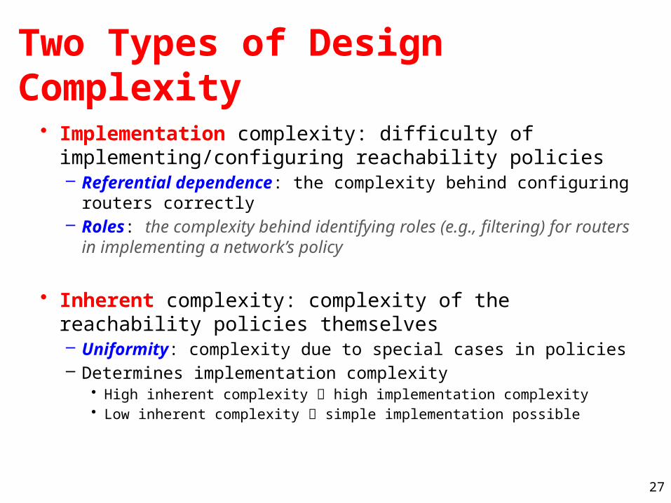
Two Types of Design Complexity
• Implementation complexity: difficulty of implementing/configuring reachability policies– Referential dependence: the complexity behind configuring
routers correctly– Roles: the complexity behind identifying roles (e.g., filtering) for
routers in implementing a network’s policy
• Inherent complexity: complexity of the reachability policies themselves– Uniformity: complexity due to special cases in policies– Determines implementation complexity
• High inherent complexity high implementation complexity• Low inherent complexity simple implementation possible

28
Naïve Metrics Don’t Work
Networks Mean file size
Number of routers
Univ-1 2535 12
Univ-2 560 19
Univ-3 3060 24
Univ-4 1526 24
Enet-1 278 10
Enet-2 200 83
Enet-3 600 19
• Size or line count not a good metric– Complex– Simple
• Need sophisticated metrics that capture configuration difficulty

29
Referential Complexity: Dependency Graph
• An abstraction derived from router configs
• Intra-file links, e.g., passive-interfaces, and access-group
• Inter-file links– Global network symbols, e.g.,
subnet, and VLANs
1 Interface Vlan901
2 ip 128.2.1.23 255.255.255.252
3 ip access-group 9 in
4 !
5 Router ospf 1
6 router-id 128.1.2.133
7 passive-interface default
8 no passive-interface Vlan901
9 no passive-interface Vlan900
10 network 128.2.0.0 0.0.255.255
11 distribute-list in 12
12 redistribute connected subnets
13 !
14 access-list 9 permit 128.2.1.23 0.0.0.3 any
15 access-list 9 deny any
16 access-list 12 permit 128.2.0.0 0.0.255.255
ospf1
Vlan901
Access-list 9
Access-list 12
Subnet 1
ospf 1
Vlan30
Access-list 11Access-list 10
Route-map 12

30
Referential Dependence Metrics
• Operator’s objective: minimize dependencies– Baseline difficulty of maintaining reference links network-wide– Dependency/interaction among units of routing policy
• Metric: # ref links normalized by # devices
• Metric: # routing instances– Distinct units of control plane policy
• Router can be part of many instances• Routing info: unfettered exchange
within instance, but filtered across instances
– Reasoning about a reference harder with number/diversity of instances
• Which instance to add a reference?• Tailor to the instance
31
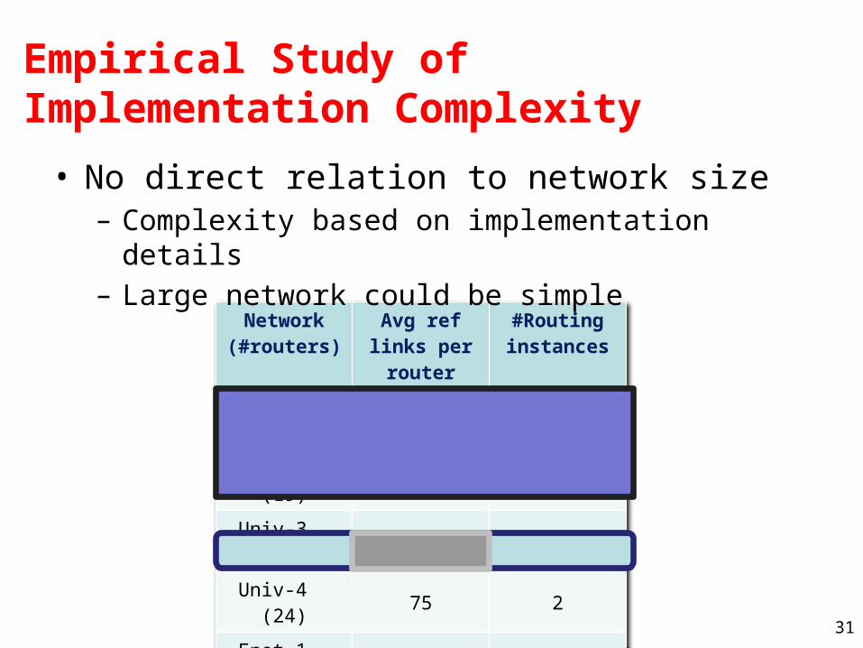
Empirical Study of Implementation Complexity
Network (#routers)
Avg ref links per router
#Routing instances
Univ-1 (12) 42 14
Univ-2 (19) 8 3
Univ-3 (24) 4 1
Univ-4 (24) 75 2
Enet-1 (10) 2 1
Enet-2 (83) 8 10
Enet-3 (19) 22 8
• No direct relation to network size– Complexity based on implementation details– Large network could be simple
32
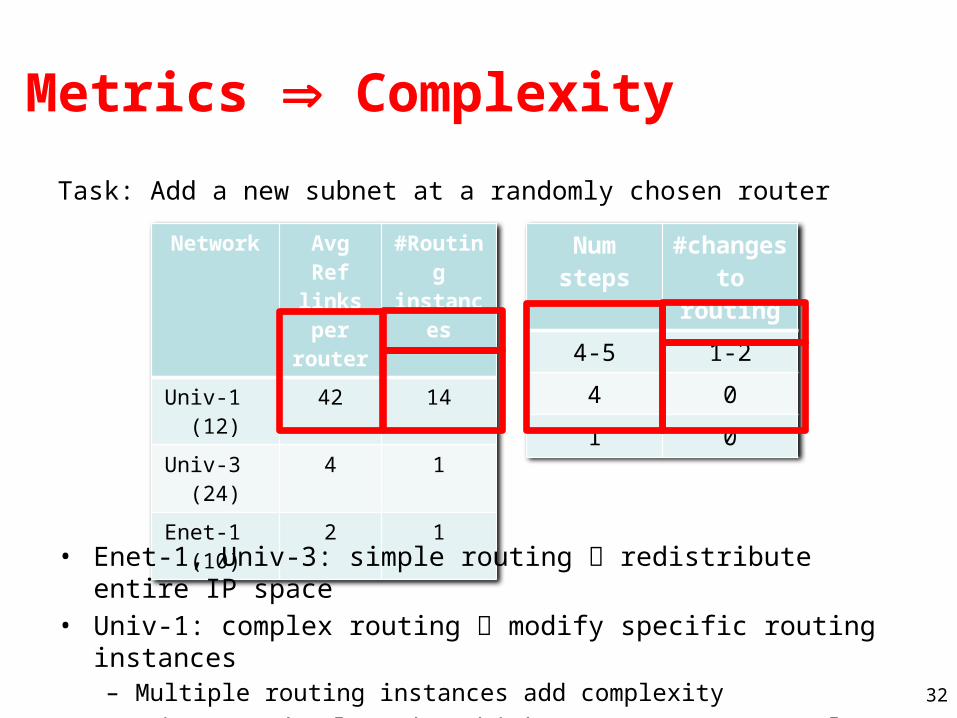
Metrics Complexity
Network Avg Ref links per
router
#Routing instance
s
Univ-1 (12)
42 14
Univ-3 (24)
4 1
Enet-1 (10)
2 1
Num steps
#changes to routing
4-5 1-2
4 0
1 0
Task: Add a new subnet at a randomly chosen router
• Enet-1, Univ-3: simple routing redistribute entire IP space• Univ-1: complex routing modify specific routing instances
– Multiple routing instances add complexity
• Metric not absolute but higher means more complex
33
Inherent Complexity
• Reachability policies determine a network’s configuration complexity– Identical or similar policies
• All-open or mostly-closed networks• Easy to configure
– Subtle distinctions across groups of users• Multiple roles, complex design, complex referential profile• Hard to configure
• Not “apparent” from configuration files– Mine implemented policies– Quantify similarities/consistency

34
Reachability Sets
• Networks policies shape packets exchanged– Metric: capture properties of sets of
packets exchanged
• Reachability set (Xie et al.): set of packets allowed between 2 routers– One reachability set for each pair of
routers (total of N2 for a network with N routers)
– Affected by data/control plane mechanisms
• Approach– Simulate control plane– Normalized ACL representation for
FIBs– Intersect FIBs and data plane ACLs
FIB ACL
FIB ACL
35
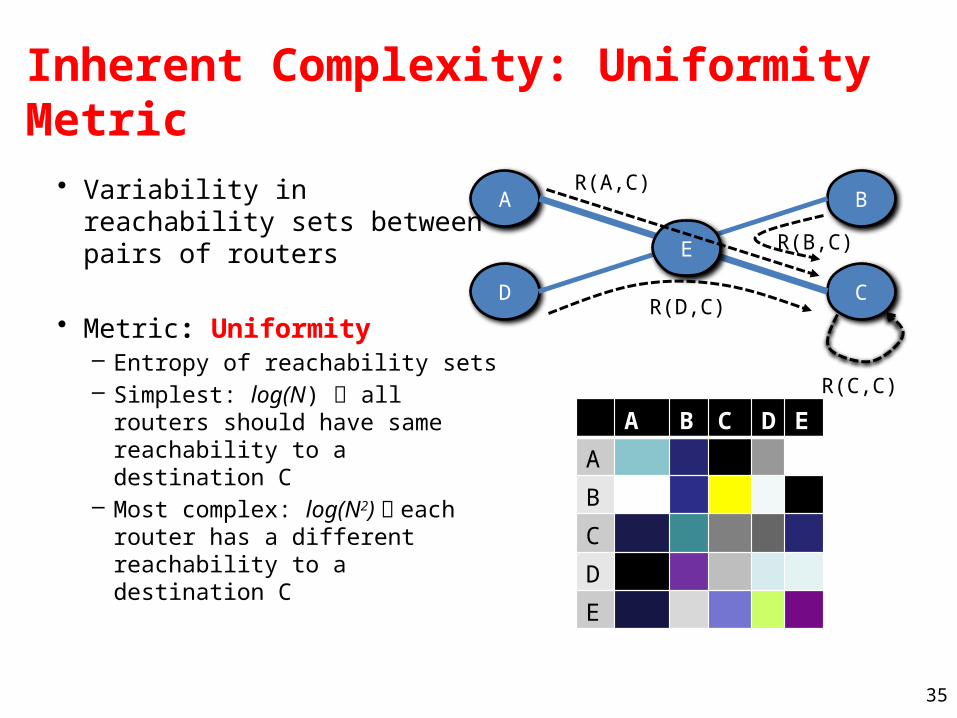
Inherent Complexity: Uniformity Metric
• Variability in reachability sets between pairs of routers
• Metric: Uniformity– Entropy of reachability sets– Simplest: log(N) all routers
should have same reachability to a destination C
– Most complex: log(N2) each router has a different reachability to a destination C
A B
CD
E
R(A,C)
R(D,C)
R(B,C)
R(C,C)
A B C D E
A
B
C
D
E
A B C D E
A
B
C
D
E

36
Network
Entropy (diff from ideal)
Univ-1 3.61 (0.03)
Univ-2 6.14 (1.62)
Univ-3 4.63 (0.05)
Univ-4 5.70 (1.12)
Enet-1 2.8 (0.0)
Enet-2 6.69 (0.22)
Enet-3 5.34 (1.09)
Empirical Results• Simple policies
– Entropy close to ideal
• Univ-3 & Enet-1: simple policy – Filtering at higher levels
• Univ-1:– Router was not
redistributing local subnet
BUG!Network
(#routers)Avg Ref links per
router
#Routing instances
Univ-1 (12) 42 14

37
Insights
• Studied networks have complex configuration, But, inherently simple policies
• Network evolution– Univ-1: dangling references– Univ-2: caught in the midst of a major
restructuring
• Optimizing for cost and scalability– Univ-1: simple policy, complex config– Cheaper to use OSPF on core
routers and RIP on edge routers• Only RIP is not scalable• Only OSPF is too expensive
Networks(#routers)
Ref
links
Entropy(diff from
ideal)
Univ-1(12)
42 3.61 (0.03)
Univ-2(19)
8 6.14 (1.62)
Univ-3(24)
4 4.63 (0.05)
Univ-4(24)
75 5.70 (1.12)
Enet-1(10)
2 2.8 (0.0)
Enet-2(83)
8 6.69 (0.22)
Enet-3(19)
22 5.34 (1.09)

38
(Toward) Mitigating complexity –Mining policy
39
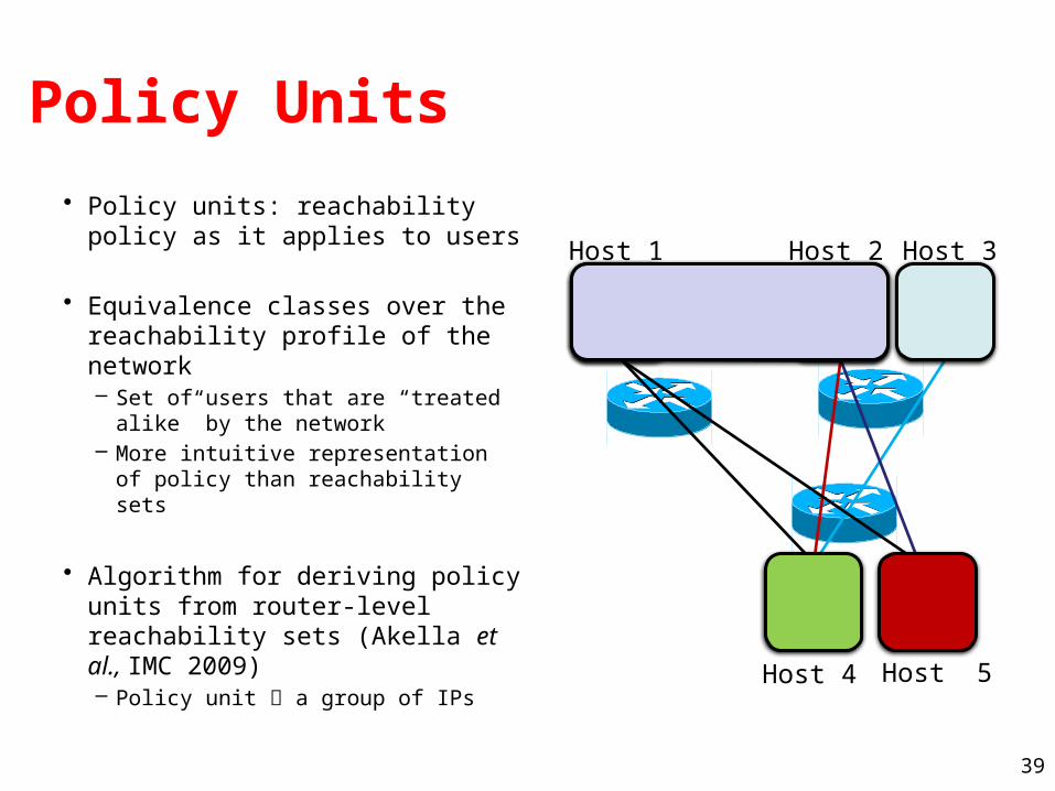
Policy Units
• Policy units: reachability policy as it applies to users
• Equivalence classes over the reachability profile of the network– Set of users that are “treated
alike” by the network– More intuitive representation of
policy than reachability sets
• Algorithm for deriving policy units from router-level reachability sets (Akella et al., IMC 2009)– Policy unit a group of IPs
Host 1 Host 2 Host 3
Host 4 Host 5

40
Policy Units in Enterprises
Name # Subnets # Policy Units
Univ-1 942 2
Univ-2 869 2
Univ-3 617 15
Enet-1 98 1
Enet-2 142 40
• Policy units succinctly describe network policy
• Two classes of enterprises• Policy-lite: simple with few units
• Mostly “default open”• Policy-heavy: complex with many units

41
Policy units: Policy-heavy Enterprise
• Dichotomy:– “Default-on”: units 7—15 – “Default-off”: units 1—6
• Design separate mechanisms to realize default-off and default-off network parts– Complexity metrics to design the simplest such network [Ongoing]
42
Conclusion
43
Deconstructing Network Complexity
• Metrics that capture complexity of network configuration– Predict difficulty of making changes– Static, layer-3 configuration– Inform current and future network design
• Policy unit extraction– Useful in management and as invariant in redesign
• Empirical study– Simple policies are often implemented in complex ways– Complexity introduced by non-technical factors– Can simplify existing designs

44
Many open issues…
• Comprehensive metrics (other layers)• Simplification framework, config “remapping”• Cross-vendor? Cross-architecture?• ISP networks vs. enterprises• Application design informed by complexity


![Nick Feamster - Princeton University Computer Sciencefeamster/cv/cv-feb2017.pdf · Publications Theses [1] Nick Feamster. Proactive Techniques for Correct and Predictable Internet](https://static.documents.pub/doc/80x56/5abef3157f8b9a8e3f8da109/nick-feamster-princeton-university-computer-science-feamstercvcv-feb2017pdfpublications.jpg)


