Before attempting to connect or operate this product, please read these instructions carefully and save this manual for future use. Model No. WJ-NT104 Network Interface Unit Operating Instructions OPERATE RCV XMT LINK Network Interface Unit WJ-NT104
Transcript
Before attempting to connect or operate this product,please read these instructions carefully and save this manual for future use.
Model No. WJ-NT104
Network Interface UnitOperating Instructions
OPERATE
RCV XMTLINK
Network Interface Unit WJ-NT104
2
The serial number of this product may be found on the bot-tom of the unit.You should note the serial number of this unit in the spaceprovided and retain this book as a permanent record of yourpurchase to aid identification in the event of theft.
Model No.
Serial No.
WARNING:To reduce the risk of fire or electric shock, do not expose this appliance to rain or moisture.
The lightning flash with arrowhead sym-bol, within an equilateral triangle, isintended to alert the user to the pres-ence of uninsulated "dangerous voltage"within the product's enclosure that maybe of sufficient magnitude to constitute arisk of electric shock to persons.
The exclamation point within an equilat-eral triangle is intended to alert the userto the presence of important operatingand maintenance (servicing) instructionsin the literature accompanying the appli-ance.
CAUTION: TO REDUCE THE RISK OF ELECTRIC SHOCK,
DO NOT REMOVE COVER (OR BACK).
NO USER-SERVICEABLE PARTS INSIDE.
REFER SERVICING TO QUALIFIED SERVICE PERSONNEL.
CAUTIONRISK OF ELECTRIC SHOCK
DO NOT OPEN
SA 1965
SA 1966
NOTE: This equipment has been tested and found to complywith the limits for a Class A digital device, pursuant to Part15 of the FCC Rules. These limits are designed to providereasonable protection against harmful interference when theequipment is operated in a commercial environment. Thisequipment generates, uses, and can radiate radio frequencyenergy and, if not installed and used in accordance with theinstruction manual, may cause harmful interference to radiocommunications.Operation of this equipment in a residential area is likely tocause harmful interference in which case the user will berequired to correct the interference at his own expense.
FCC Caution: To assure continued compliance, (example -use only shielded interface cables when connecting to com-puter or peripheral devices). Any changes or modificationsnot expressly approved by the party responsible for compli-ance could void the user’s authority to operate this equip-ment.
For U.S.A
Caution:Before attempting to connect or operate this product,please read the label on the bottom.
3
CONTENTSPREFACE ....................................................................................................................................................................................... 4FEATURES ..................................................................................................................................................................................... 4PRECAUTIONS .............................................................................................................................................................................. 5MAJOR OPERATING CONTROLS AND THEIR FUNCTIONS ....................................................................................................... 6
Front View ............................................................................................................................................................................... 6 Rear View ................................................................................................................................................................................ 6
INSTALLATIONS ........................................................................................................................................................................... 8 Mounting in the Rack .............................................................................................................................................................. 8
SYSTEM CONNECTIONS ............................................................................................................................................................. 10 LAN Type Connection ........................................................................................................................................................... 10 PPP (Point to Point Protocol) Type Connection ..................................................................................................................... 11
PREPARATIONS ........................................................................................................................................................................... 12 LAN Type Connection ........................................................................................................................................................... 12 Setup for WJ-NT104 .............................................................................................................................................................. 15 PPP Type Connection 1 (P to P ACCESS) ............................................................................................................................. 16 PPP Type Connection 2 (NETWORK ACCESS) ..................................................................................................................... 22
MAIN PAGE AND CONTROLS ..................................................................................................................................................... 25 Main Page and Control Windows .......................................................................................................................................... 25 Operation Mode ..................................................................................................................................................................... 26 Pull Mode and Push Mode .................................................................................................................................................... 28 Picture Quality Setup ............................................................................................................................................................. 29 MAIN PAGE (without Camera Control) .................................................................................................................................. 30 MAIN PAGE (with Camera Control) ....................................................................................................................................... 32
SETUP PROCEDURES ................................................................................................................................................................. 40 How to Read ADMINISTRATOR SETUP PAGE ..................................................................................................................... 40 MODE SETUP ........................................................................................................................................................................ 41 NETWORK SETUP ................................................................................................................................................................. 44 ALARM SETUP ...................................................................................................................................................................... 45 SERIAL PORT SETUP ............................................................................................................................................................ 47 MODEM SETUP ..................................................................................................................................................................... 48 USER SETUP ......................................................................................................................................................................... 49 HOST SETUP ......................................................................................................................................................................... 50 DATE & TIME SETUP ............................................................................................................................................................. 51 CAMERA MENU SETUP ........................................................................................................................................................ 52
UTILITY SOFTWARE ..................................................................................................................................................................... 53 Network Setup ....................................................................................................................................................................... 53 Camera Menu Setup .............................................................................................................................................................. 55
ACCESS AUTHORIZATION .......................................................................................................................................................... 56 Control of Access Authorization ............................................................................................................................................ 56 Access Level ......................................................................................................................................................................... 56 Registration ............................................................................................................................................................................ 56
EXTEND FUNCTION ..................................................................................................................................................................... 58 WJ-FS616 Video Multiplexer Control ..................................................................................................................................... 58 WJ-SX550A Matrix Switcher Control ...................................................................................................................................... 60 WJ-DR200 AV Disk Recorder Control ................................................................................................................................... 63
CONTROL BY HTML DESCRIPTION ............................................................................................................................................ 67 Image Display ........................................................................................................................................................................ 67 Camera Operation ................................................................................................................................................................. 68 Alarm Operation .................................................................................................................................................................... 72 Substitution Character Strings in HTTP Server ...................................................................................................................... 73
TROUBLESHOOTING .................................................................................................................................................................. 75INSTRUMENTS TO BE CONNECTED .......................................................................................................................................... 76SPECIFICATIONS ......................................................................................................................................................................... 77STANDARD ACCESSORIES ......................................................................................................................................................... 77
4
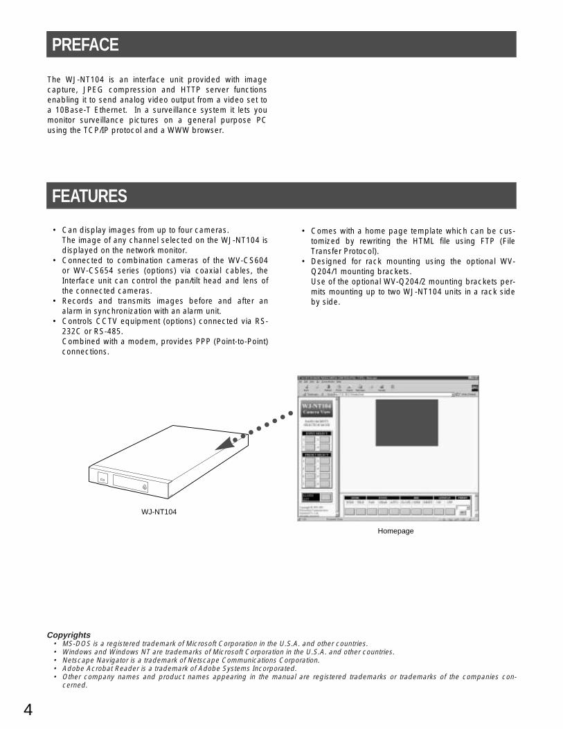
The WJ-NT104 is an interface unit provided with imagecapture, JPEG compression and HTTP server functionsenabling it to send analog video output from a video set toa 10Base-T Ethernet. In a surveillance system it lets youmonitor surveillance pictures on a general purpose PCusing the TCP/IP protocol and a WWW browser.
PREFACE
FEATURES
• Can display images from up to four cameras.The image of any channel selected on the WJ-NT104 isdisplayed on the network monitor.
• Connected to combination cameras of the WV-CS604or WV-CS654 series (options) via coaxial cables, theInterface unit can control the pan/tilt head and lens ofthe connected cameras.
• Records and transmits images before and after analarm in synchronization with an alarm unit.
• Controls CCTV equipment (options) connected via RS-232C or RS-485.Combined with a modem, provides PPP (Point-to-Point)connections.
• Comes with a home page template which can be cus-tomized by rewriting the HTML file using FTP (FileTransfer Protocol).
• Designed for rack mounting using the optional WV-Q204/1 mounting brackets.Use of the optional WV-Q204/2 mounting brackets per-mits mounting up to two WJ-NT104 units in a rack sideby side.
Homepage
WJ-NT104
Copyrights• MS-DOS is a registered trademark of Microsoft Corporation in the U.S.A. and other countries.• Windows and Windows NT are trademarks of Microsoft Corporation in the U.S.A. and other countries.• Netscape Navigator is a trademark of Netscape Communications Corporation.• Adobe Acrobat Reader is a trademark of Adobe Systems Incorporated.• Other company names and product names appearing in the manual are registered trademarks or trademarks of the companies con-
cerned.
5
PRECAUTIONS
• Refer all work related to the installation of this prod-uct to qualified service personnel or systeminstallers.
• Do not attempt to disassemble the appliance.To prevent electric shock, do not remove screws orcovers.There are no user-serviceable parts inside. Contactqualified service personnel for maintenance.
• Handle the appliance with care.Do not strike or shake, as this may damage the appli-ance.
• Do not expose the appliance to water or moisture,nor try to operate it in wet areas.Do take immediate action if the appliance becomeswet. Turn the power off and refer servicing to qualifiedservice personnel. Moisture may damage the appli-ance and also cause electric shock.
• Do not use strong or abrasive detergents whencleaning the appliance body.Use a dry cloth to clean the appliance when it is dirty.When the dirt is hard to remove, use a mild detergentand wipe gently.
• Do not operate the appliance beyond its specifiedtemperature, humidity or power source ratings.Do not use the appliance in an extreme environmentwhere high temperature or high humidity exists.Use the appliance at temperatures within −10°C -+50°C (14°F - 122°F) and a humidity below 90 %.The input power source for this appliance is 120 V AC60 Hz.
6
MAJOR OPERATING CONTROLS AND THEIR FUNCTIONS
Front View
Rear View
RS−232C
G 8 7 6 5 G4 3 2 1G B A G B A
XMT RCV SET UP
RS485
VIDEO
IN 4 3 2 1
4 3 2 1OUT
ALARM
DC 12VIN
10BASE-T
o !0 !1 !2
!3 !4 !5 !6 !7
LINK RCV XMTOPERATE
Network Interface Unit WJ-NT104
LINK RCV XMTOPERATE
Network Interface Unit WJ-NT104
RS232C MODERESET
q w e r
t
y u i
q Operate indicator [OPERATE]Is on while the power of the WJ-NT104 is turned on.
w Link indicator [LINK]Lights when the unit is connected to a normally operat-ing network.
e Receiving indicator [RCV]Lights when data is received from the network.
r Transmitting indicator [XMT]Lights when data is transmitted to the network.
t Front panel
y Reset button [RESET]Used to set or change a mode, or to restart.
u RS-232C port [RS232]Used as an alternative to the RS-232C port !4 on therear panel.
RS-485 mode
i Mode selector [MODE]Used to set a mode.Set all the switches to OFF exceptwhen setting a mode.
• SW1To initialize the IP address (IP=192.168.0.10) orother data already set.
• It takes about 10 seconds after SW1 is set toON and the RESET button is pressed for thedata to be initialized.
• After initializing, set SW1 back to OFF andpress the RESET button again to restart.
• SW2To return the HTML file, JPEG or other image datastored in the WJ-NT104 to the factory default set-tings. The IP address and other setup data will notbe initialized.
7
o Video input connectors [VIDEO IN 1/2/3/4] (BNC)Used to connect cameras.
!0 RS-485 connectors [XMT/RCV]To connect the control data cables of combinationcameras (options)
!1 RS-485 setup switches [RS485 SETUP]Used when combination cameras with an RS-485 inter-face are connected.
MODE
1 2 3 4 5 6 7 8 9 10ON
Switch Positions
SW1
OFF
SW2
OFF
SW3
OFF
SW4
OFF
SW5
OFF
SW6
OFF
SW7
OFF
SW8
OFF
SW9
OFF
SW10
OFFTo operate
ON ON OFF OFF OFF OFF OFF OFF OFF OFFTo initialize
SW1
ON
ON
OFF
OFF
SW2
ON
OFF
ON
OFF
SW3
ON
OFF
ON
ON
SW4
ON
ON
ON
ON
Half Duplex (2 Lines)/termination ON
Full Duplex (4 Lines)/termination ON
Half Duplex (2 Lines)/termination OFF
Full Duplex (4 Lines)/termination OFF
• It takes a few minutes after SW2 is set to ONand the RESET button is pressed for the datato be initialized.
• After initializing, set SW2 back to OFF andpress the RESET button again to restart.
To return all data, including settings and homepage, to the factory default settings, set both SW1and SW2 to ON and press the RESET button.
• SW3, SW4, SW5, SW6, SW7, SW8, SW10Keep these in the OFF position.
• SW9Selects the RS-232C port (front or rear panel).Setting SW9 to OFF selects the rear panel port,setting it to ON selects the front panel port.
!5 Ethernet port [10BASE-T]To connect a 10Base-T cable.
!6 DC power connector [DC 12V IN]To connect the AC adapter (accessory).
!7 Cord clamp (accessory)To clamp the cord of the AC adapter (accessory).Insert the clamp into the hole in the rear panel shownbelow.
DC12V
10BASE-T
ALARM
IN
Cord clamp
!2 Alarm input/output port [ALARM]To connect an external alarm unit. Input and output canbe changed from the ADMINISTRATOR SETUP PAGE.
!3 Video output connectors [VIDEO OUT 1/2/3/4] (BNC)The video signal connected to VIDEO IN is loopedthrough to this connector.
!4 RS-232C port [RS-232C]To connect a modem or CCTV equipment for control-ling the system.
SET UP
1 2 3 4ON
8
The installation described below should be made by qualified service personal or system installers.
Mounting in a Rack
The WJ-NT104 can be mounted in a rack using the optional WV-Q204/1 mounting brackets.Use of the optional WV-204/2 mounting brackets permits mounting up to two WJ-NT104 units in a rack side by side.
INSTALLATIONS
Rubber feet
Rack mountingbracket (small)
Rack mountingbracket (large)
Joint metal Remove 2 screws from the rear beforehand.
Rack mountingbracket (small)
Rack mountingbracket (small)
1. Remove the four rubber feet by removing the four screws from the bottom of the WJ-NT104.
Mounting one WJ-NT104 with the WV-Q204/12. Fix the mounting brackets (large and small) on both sides of the WJ-NT104 with the eight supplied screws (M3x8) as
shown below.
Mounting two WJ-NT104 with the WV-Q204/22. Place the joint metals on the WJ-NT104 units as shown below and fix them with the twelve supplied screws (M3x6)
Note: Remove two screws from the rear of the WJ-NT104 beforehand.
Fix the mounting brackets (small) on both sides of the WJ-NT104 units with the eight supplied screws (M3x8) as shownbelow.
9
3. Install the WJ-NT104 with the rack mounting brackets inthe rack by using four screws (not included).
Rack mounting screws
Mounting two WJ-NT104s
Cautions:• Do not block the ventilation opening or slots in the
cover to prevent the appliance from overheating.Always keep the temperature in the rack within+50°C (122°F).
• Secure the rear of the appliance to the rack byusing additional mounting brackets (procuredlocally) if the rack is subject to vibration.
10
SYSTEM CONNECTIONS
The WJ-NT104 can be operated either in a LAN type connection to an Ethernet or a PPP type connection to a public line via amodem/terminal adapter (TA).
LAN Type ConnectionFor LAN type connection, it is necessary to set the IP address, netmask, and default gateway of the WJ-NT104 according toyour LAN environment.
Access from a PC on the same subnetShown below is an example of direct access from a client PC on the same subnet.IP address and netmask must be properly set.
PC (browser)
LAN
Ethernet(10Base-T Cable)
WJ-NT104
Camera (max. 4)
WJ-NT104
LAN LAN
PC (browser)
Router
Camera (max. 4)
Access from PCs via routersShown below is an example of monitoring from PCs on two or more subnets via routers, for example.IP address, netmask and default gateway must be properly set.
WJ-NT104
Router RouterCSU/DSUIMUX
CSU/DSUIMUX
Serial Serial
Leased lines
LANLAN
Camera (max. 4)
PC
Access between LAN and LANShown below is an example of monitoring from two PCs at different sites through a LAN connection, for example.IP address, netmask, default gateway and routing table must be properly set.
11
PPP (Point to Point Protocol) Type Connection Access from a Client PC to the WJ-NT104
• Direct connection to the WJ-NT104In this configuration, a client PC accesses the WJ-NT104 via a public line using PPP (Point to Point Protocol). With PPPMODE in the NETWORK SETUP dialog box set to P to P ACCESS, the WJ-NT104 can be accessed by a PC runningWindows95, for example.
WJ-NT104Modem/TACSU/DSU
Modem/TACSU/DSU
Serial Serial
Public lines
Dial-up server/router etc.
LAN
Camera (max. 4)
PC (Windows95 etc.)
PC (Windows 95 etc.)
Serial
Modelm/TAWJ-NT104
Modelm/TA
Serial
Public lines
Camera (max. 4)
WJ-NT104
Modem/TA Modem/TA
Serial Serial
Public lines
LAN
Camera (max. 4)
PC (WindowsNT etc.)
• Connection via a dial-up server (or a router)Set an WJ-NT104 telephone number and IP address in the dial-up server (or ISDN, POTS router) in advance. This configu-ration enables the dial-up server to access the WJ-NT104 using PPP (Point to Point Protocol) when a PC specifies the setaddress. With PPP MODE in the NETWORK SETUP dialog box set to NETWORK ACCESS, the WJ-NT104 can beaccessed by a PC running Windows95, for example.
Access from the WJ-NT104 to a Client PCSet the telephone number, user name, password, etc. of the client PC in the WJ-NT104.In this configuration, the WJ-NT104 calls the registered destination and accesses it using PPP (Point to Point Protocol)when an alarm input is received.
12
PREPARATIONS
∗ Requires a PC satisfying the following conditions.
• OS: Windows95, Windows98 or Windows NT4.0• WWW browser active
Recommended browser > Internet Explorer Ver 4.0 or higher Netscape Navigator Ver. 4.04 orhigher
• Display resolution: 800 x 600 pixels or more
To PC directly or via hub AC adapter (Accessory)
Camera
10Base-T cable
RS−232C
G 8 7 6 5 G4 3 2 1G B A G B A
XMT RCV SET UP
RS485
VIDEO
IN 4 3 2 1
4 3 2 1OUT
ALARM
DC 12VIN
10BASE-T
LAN Type ConnectionThe figure below shows how the WJ-NT104 can be connected directly to a PC for testing before it is connected directly toa network. The connection can also be made via a hub.
Direct Connection to a PC without HubConnect the 10Base-T port on the PC to the Ethernet port on the WJ-NT104 with a crossover cable.
PC (browser)
Ethernet crossover cable
WJ-NT104
Camera (max. 4)
PC (browser)Hub
Ethernetstraight cable
Ethernetstraight cable
WJ-NT104
Camera (max. 4)
Connection to a Client PC via HubConnect the 10Base-T port on the PC to the Ethernet port on the WJ-NT104 with straight cables via a hub.
12345678
12345678
13
PC SetupThe factory default settings of the WJ-NT104 are as fol-lows:
IP address
Netmask
Default gateway
192.168.0.10
255.255.255.0
192.168.0.1
For a client PC to access WJ-NT104 factory default set-tings, set the IP address of the PC to 192.168.0.XX (XXmeans any number from 2 to 254 except 10).
q Connect the WJ-NT104 to the PC. (See page 12.)
w Change the PC’s TCP/IP to match the factory defaultsettings of the WJ-NT104.
If your PC's OS is Windows95 or Windows98, proceedas follows:
(1) Click the Start button, point to settings, and thenclick Control Panel.
(2) Double-click Network.
(3) In the Network dialog box, click the Configurationtab.
(4) Choose TCP/IP, and then click the [Properties]button to display the TCP/IP Properties dialogbox.
(5) Specify an IP address as follows:IP Address: 192.168.0.9Subnet Mask: 255.255.255.0
e Restart the PC.Start the WWW browser, and select [Do not use proxyfor address 192.168.0.10].
14
If your browser is Netscape Navigator, proceed as fol-lows:
(1) Click the Edit menu, and then click Preferences.
(2) In the Preferences dialog box, click Advanced,and then click Proxies.
(3) Select the Manual proxy configuration option,and then click the [View] button to display theManual Proxy Configuration dialog box.
(4) In the space [Do not use proxy servers fordomains beginning with:], specify 192.168.0.10.
r In the Location bar, specify http://192.168.0.10.
t The browser displays the MAIN PAGE of the WJ-NT104's home page. If there is a camera input, it alsodisplays the camera image.
y Click [button] on the home page and verify the func-tions of the WJ-NT104.For details on home page operations see MAIN PAGEon page 30.
15
IP Address Setting via LAN Connectionq On the Location bar, enter http://192.168.0.10/hwset-
up.html to display the ADMINISTRATOR SETUPPAGE.To open the ADMINISTRATOR SETUP PAGE, youneed to enter your user ID and password. The defaultID and password are [admin] and [nil], respectively.Click the [NETWORK] button to display the NETWORKSETUP dialog box.
w Set IP-ADDRESS, NETMASK, DEFAULT GATEWAY.Consult your network administrator for the correct set-tings.
e Specify the TCP/IP settings for the PC.If the PC is already operating on a network, specify itsoriginal IP address in the TCP/IP Properties dialog box(before changing it to 192.168.0.9).
WJ-NT104 SetupFirst, it is necessary to set an IP address for the WJ-NT104 according to the operating environment. Consult your networkadministrator for the address to set.
If the PC is running Windows95 or Windows98, selectControl Panel / Network / Configuration, click the[Properties] button to open the TCP/ IP Propertiesdialog box, and enter the IP address. Refer to the set-tings on page 13.
r Restart the PC.
t Start the PC’s browser.Specify http://(IP address set in the WJ-NT104)/ in theLocation bar. The connection is established when theimage from the WJ-NT104 is displayed on the PCscreen.
Note: Refer page 14 for further details.
IP Address Setting via RS-232CConnectionFor further information, refer to page 53.
16
PPP Type Connection 1 (P to P ACCESS)To use this mode, match the IP address of the PC with the address of the WJ-NT104.The WJ-NT104 permits PPP (Point-to-Point Protocol) connection via a public line or the ISDN by connecting it to a modemor a terminal adapter (TA).
PC (Windows 95 etc.)
Serial
Modelm/TAWJ-NT104
Modelm/TA
Serial
Public lines
Camera (max. 4)
Setup ProceduresTo set up the PPP connection, access the WJ-NT104 from a PC via a LAN and open the ADMINISTRATOR SETUP PAGE.If the WJ-NT104 is already connected to a LAN, go to the Location bar and specify http://192.168.0.10 (or IP address set previ-ously)/hwsetup.html to display the ADMINISTRATOR SETUP PAGE. If it is not yet connected to a LAN, connect to the LANfollowing the procedures described under "PREPARATIONS" (p. 12) and specify hwsetup.html to open the ADMINISTRATORSETUP PAGE.
q On the ADMINISTRATOR SETUP PAGE, click the[SERIAL PORT] button to open the SERIAL PORTSETUP dialog box.
Set these items to match the settings of themodem/TA used. If the settings of the modem/TA are unknown, set 57 600 bps (see note), 8bit, 1 bit, NONE, and NONE, respectively.
Note: Set a baud rate (net nec.) close to that of themodem or TA connected. If there is a large differ-ence, it may take much longer for images toappear.
w Click the [SET&REBOOT] button to save the settings.
17
e On the ADMINISTRATOR SETUP PAGE, click the [MODEM] button to open the MODEM/TA SETUP dialog box.Make the necessary entries for MODEM MODELS, MODEM INITIALIZE COMMAND (specify directly), LINE TYPE,LOCAL TELEPHONE NUMBER, DESTINATION TELEPHONE NUMBER, LOGON ID, LOGON PASSWORD and REDIAL(NUMBER OF TIMES/INTERVAL).
r Click the [SET] button to save.
t On the ADMINISTRATOR SETUP PAGE, click the [NETWORK] button to open the NETWORK SETUP dialog box. ForNETWORK TYPE, mark PPP.
y Click the [SET & REBOOT] button to save.The WJ-NT104 is switched from LAN connection mode to PPP connection mode.
u Connect the RS-232C port on the rear panel of the WJ-NT104 to the RS-232C port on the modem/TA with a crossovercable, and access the WJ-NT104 from a client PC via the modem/TA.
18
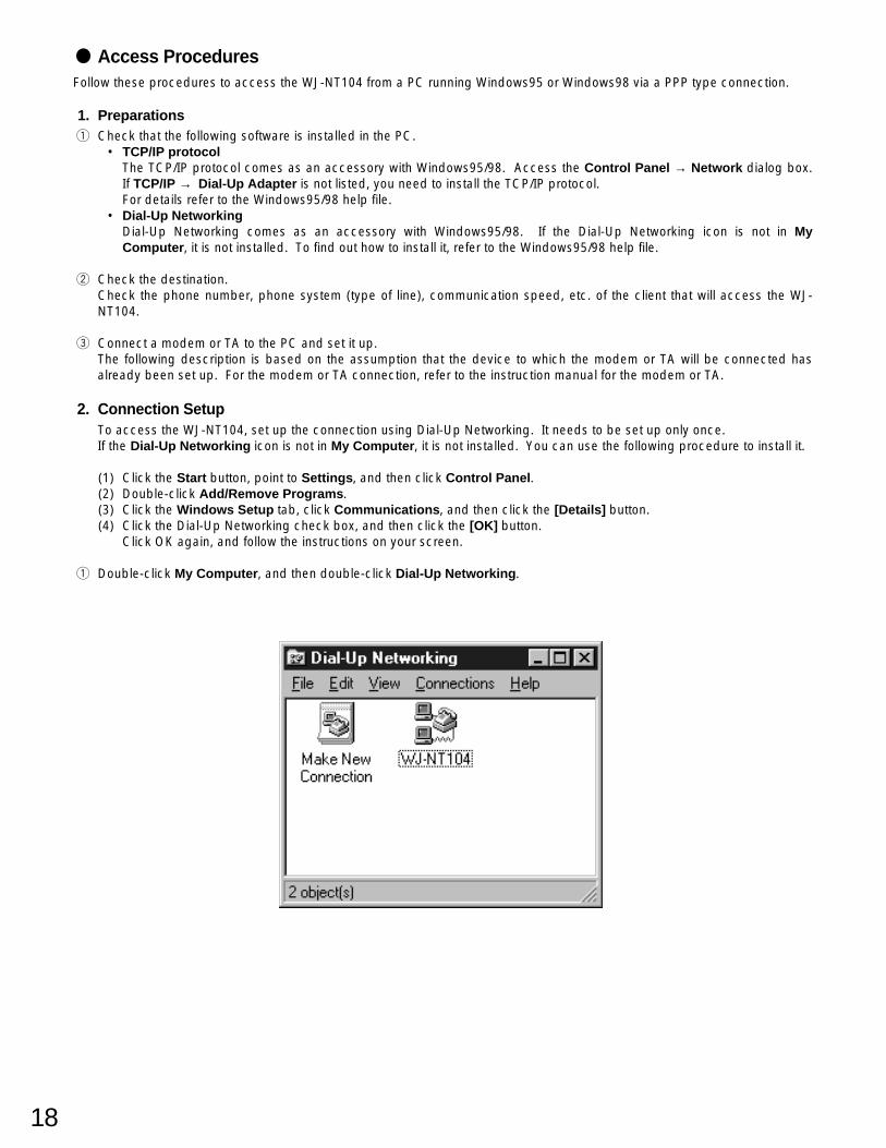
Access ProceduresFollow these procedures to access the WJ-NT104 from a PC running Windows95 or Windows98 via a PPP type connection.
1. Preparationsq Check that the following software is installed in the PC.
• TCP/IP protocolThe TCP/IP protocol comes as an accessory with Windows95/98. Access the Control Panel → Network dialog box.If TCP/IP → Dial-Up Adapter is not listed, you need to install the TCP/IP protocol.For details refer to the Windows95/98 help file.
• Dial-Up NetworkingDial-Up Networking comes as an accessory with Windows95/98. If the Dial-Up Networking icon is not in MyComputer, it is not installed. To find out how to install it, refer to the Windows95/98 help file.
w Check the destination.Check the phone number, phone system (type of line), communication speed, etc. of the client that will access the WJ-NT104.
e Connect a modem or TA to the PC and set it up.The following description is based on the assumption that the device to which the modem or TA will be connected hasalready been set up. For the modem or TA connection, refer to the instruction manual for the modem or TA.
2. Connection SetupTo access the WJ-NT104, set up the connection using Dial-Up Networking. It needs to be set up only once.If the Dial-Up Networking icon is not in My Computer, it is not installed. You can use the following procedure to install it.
(1) Click the Start button, point to Settings, and then click Control Panel.(2) Double-click Add/Remove Programs.(3) Click the Windows Setup tab, click Communications, and then click the [Details] button.(4) Click the Dial-Up Networking check box, and then click the [OK] button.
Click OK again, and follow the instructions on your screen.
q Double-click My Computer, and then double-click Dial-Up Networking.
19
w Double-click the Make New Connection icon.
e Type a name for the PC and select a modem. Then click the [Next] button.
r Enter the phone number and click the [Next>] button.A message appears, reading [You have successfully created a new Dial-Up Networking connection called:].
t Click the [Finish] button.The screen returns to the Dial-Up Networking window.The newly created icon is displayed.
y Right-click the new icon to display the pull-down menu, and then click Properties.
20
y Click the [Server Type...] button.
u For Type of Dial-up Server, select PPP: Windows95, Windows NT 3.5, Internet (for Windows95), or PPP:Windows95/98, Windows NT 4.0, Internet (for Windows98).
i Remove all checks in the Advanced options field.
o Check TCP/IP in the Allowed network protocols field.
!0 Click the [TCP/IP Settings....] button to display the TCP/IP Settings dialog box.
!1 Check Server assigned IP address.
!2 Check Server assigned name server addresses.
!3 Remove checks from User IP header compression and Use default gateway on remote network.
!4 Click the [OK] button.The screen returns to the Server Types dialog box. Click the [OK] button and click it again.
21
3. Access Proceduresq Double-click the new icon in the Dial-Up Networking window.
w After checking the contents of the dialog box, click the [Connect] button.The Connection Established dialog box is displayed after a short delay to indicate that the connection is under way.
* With some versions of Windows95 this dialog box is not displayed.
e Double-click the icon shown on the task bar to display the Connected to WJ-NT104 dialog box which indicates that theconnection is under way.
r To disconnect, click the [Disconnect] button.
22
PPP Type Connection 2 (NETWORK ACCESS)1. Windows NT Setup
q When installed, Remote Access Service appears in thelist of Network Services.In the Network dialog box, choose Remote AccessService, and then click the [Properties] button to dis-play the Remote Access Setup window.
w Click the [Configure] button and configure the port inthe Configure Port Usage dialog box. Then click [OK]to return to the Remote Access Setup window of Stepq.
e Click the [Network...] button and set the protocolsused in the Network Configuration dialog box as fol-lows:
r Check TCP/IP in the Dial out Protocols field.
t Check TCP/IP in the Allow remote clients runningfield.
y Check Allow any authentication including clear testin the Encryption settings field.
If the Dial-Up Networking icon is not in My Computer, it is not installed. You can use the following procedure to install it.(1) Right-click the Network Neighborhood icon on the desktop, and then click Properties in the pull-down menu.(2) In Network dialog box, click the Services tab.(3) If the Remote Access Service is not in the Network Services list, click the [Add] button to display the Select Network
Service dialog box.(4) Choose Remote Access Service, and then click the [OK] button to display the Windows NT Setup dialog box.(5) Click the [Continue] button in the dialog box to install Remote Access Service.
WJ-NT104Modem/TACSU/DSU
Modem/TACSU/DSU
Serial Serial
Public lines
Dial-up server/router etc.
LAN
Camera (max. 4)
PC (Windows95 etc.)
23
u Click the [Configure...] button to display the RAS Server TCP/IP Configuration dialog box.
i Check Entire network in the Allow remote TCP/IP clients to access field.o Check Use static address pool under Choose Cancel if you do not want to allow remote TCP/IP clients to dial in.
!0 Set Begin and End of an address.The above dialog box setting applies in cases where addresses from 192.168.1.10 to 192.168.1.15 can be pooled.Click the [OK] button.
!1 Set Remote Access Admin to grant remote access permission to users. To activate the Remote Access Admin.(1) Click the Start button, point to Programs, and then Administrative Tools.(2) Click Remote Access Admin.(3) Point to Users menu and then click Permissions to display the Remote Access Permissions window.
!2 Select a user to whom remote access permission is to be granted, and check Grant dialin permission to user.
!3 Click the [OK] button.
24
2. Windows98 SetupIf the Dial-Up Networking icon is not in My Computer, it is not installed. You can use the following procedure to install it.
(1) Click the Start button, point to Settings, and then click Control Panel.(2) Double-click Add/Remove Programs.(3) Click the Windows Setup tab, click Communications, and then click the [Details] button.(4) Click the Dial-Up Networking check box, and then click the [OK] button.
Click OK again, and follow the instructions on your screen.
w If more than one modem is connected, click the tab at the top of the box and select a modem to use.
e Check Allow caller access.
r Click the [Change Password...] button.The Dial-Up Networking Password dialog box is displayed.
t Enter a password, and then click the [OK] buttonType the same password as used to set up the connection and modem/TA.
y Click the [Server Types...] button to display the Server Types dialog box.
u For Types of Dial-Up Servers, select PPP:Internet, Windows NT Server, Windows98.
i In the Advanced options field, remove checks from Enable software compression and Require encrypted password.
o Click the [OK] button.The screen returns to the Dial-Up Server dialog box. Click the [OK] button.
q Click the icon on the taskbar to display the Dial-Up Server dialog box.
25
Main Page and Control Windows
On the Location bar of the PC, type http://192.168.0.10 (or IP address set for WJ-NT104) to display the MAIN PAGEdefault window.The MAIN PAGE window is available in the following five modes:
1. Images without camera control / PULL mode2. Images without camera control / PUSH mode3. Images with camera control / PULL mode4. Images with camera control / PUSH mode5. Others
The mode 1 to 4 windows may differ slightly depending on the operation mode.
For the Main Page setup see MODE SETUP on page 41.
MAIN PAGE AND CONTROLS
26
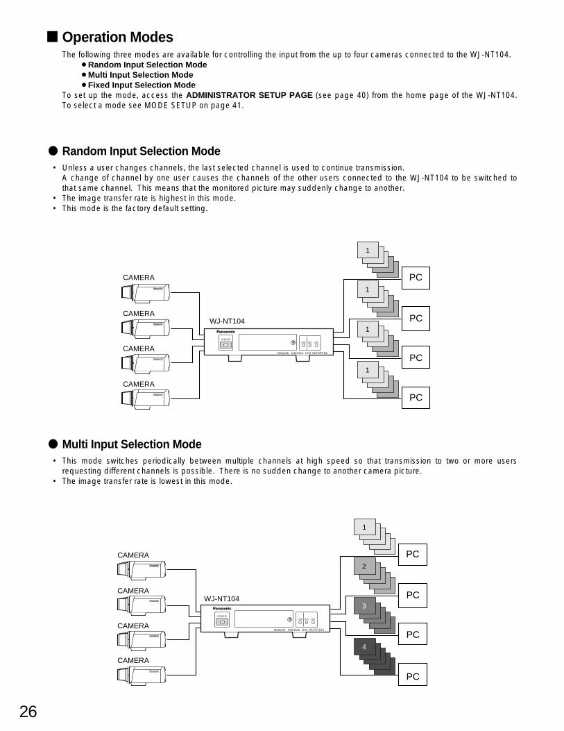
Random Input Selection Mode• Unless a user changes channels, the last selected channel is used to continue transmission.
A change of channel by one user causes the channels of the other users connected to the WJ-NT104 to be switched tothat same channel. This means that the monitored picture may suddenly change to another.
• The image transfer rate is highest in this mode.• This mode is the factory default setting.
LINK RCV XMTOPERATE
Network Interface Unit WJ-NT104
1
1
1
1
PC
PC
PC
PC
WJ-NT104
CAMERA
CAMERA
CAMERA
CAMERA
LINK RCV XMTOPERATE
Network Interface Unit WJ-NT104
1
2
3
4
PC
PC
PC
PC
WJ-NT104
CAMERA
CAMERA
CAMERA
CAMERA
Multi Input Selection Mode• This mode switches periodically between multiple channels at high speed so that transmission to two or more users
requesting different channels is possible. There is no sudden change to another camera picture.• The image transfer rate is lowest in this mode.
Operation ModesThe following three modes are available for controlling the input from the up to four cameras connected to the WJ-NT104.
To set up the mode, access the ADMINISTRATOR SETUP PAGE (see page 40) from the home page of the WJ-NT104.To select a mode see MODE SETUP on page 41.
27
LINK RCV XMTOPERATE
Network Interface Unit WJ-NT104
1
1
1
1
PC
PC
PC
PC
WJ-NT104CAMERA
LINK RCV XMTOPERATE
Network Interface Unit WJ-NT104
1
1
1
1
PC
PC
PC
PC
WJ-NT104
CAMERA
CAMERA
CAMERA
CAMERA
Channel Selection
Fixed Input Selection Mode• You cannot select other than the channels specified by ADMINISTRATION SETUP PAGE.• The image transfer rate is highest in this mode.
Sequence Mode• This is an applied version of Random Input Selection Mode, used to change channels at specified intervals.
Pan/tilt, zoom, and other camera functions cannot be controlled in this mode.
• Channels available for monitoring are limited to those specified on the ADMINIS-TRATOR SETUP PAGE.
28
Pull Mode and Push ModeThe WJ-NT104 has two modes of video output.
Pull ModeA request to receive the newest image is automatically and repeatedly sent from the PC to the WJ-NT104. The imagereceived by the PC is displayed as frame feed image (semi-animated picture). The process of sending the request, receiv-ing the data, and displaying the image on the screen is performed by the Java Script program included in the HTML.
PC (browser)
Network
WJ-NT104
Camera (max. 4)
Coaxial cable(video + control)
Request to receive the newest image is sent from personal computer.
PC (browser)
Network
WJ-NT104
Newest image is continuously sent from the WJ-NT104.
Camera (max. 4)
Coaxial cable(video + control)
Note:To display images in pull mode requires Internet Explorer 4.0, Netscape Navigator 3.0, or a browser of a newer versionwhich can execute Java Script.
Push ModeA request to send continuous images is sent from the PC to the WJ-NT104. The WJ-NT104 receives the newest image atset time intervals, and continuously sends the received images to the PC.
Note:To display images in push mode requires Netscape Navigator 3.X or a browser of a newer version. Internet Explorerdoes not support displaying images in push mode.
To select a mode see MODE SETUP on page 41.
29
Picture Quality Setup Image ResolutionThe following four image resolutions (number of picture elements) are available. The higher the resolution, the larger theimage and the lower the display speed.
q 640 x 480 pixelw 640 x 240 pixele 320 x 240 pixelr 160 x 120 pixel
Note:The display size of images received in any of the above resolutions can be changed from the WWW browser.
• Incoming images with a resolution except of 640 x 240 pixels are displayed in the size in which they are received.• Incoming images with a resolution of 640 x 240 pixels are displayed in 640 x 480 pixel size.
Image QualityThe following four image qualities (compression ratios) are available. The lower the compression ratio, the better theimage quality, but the large size of the image data file slows down the image display speed.q Super Fine (compressed to about 1/6)w Fine (compressed to about 1/10)e Normal (compressed to about 1/16)r Rough (compressed to about 1/25)
30
MAIN PAGE (without Camera Control) [index1.html]
Random Input Selection Mode
q
w
q
q INPUT SELECTThese buttons are used to switch the images of up to four cameras.A change of channel by one user causes the channels of the other users connected to the WJ-NT104 to be switched tothat same channel.
w Live image displayImages of the selected camera are displayed on the default page as semi-animated pictures.
Fixed Input Selection Mode
q Live image displayOnly the images of the camera channels specified in the MODE SETUP window are displayed.Note: Ordinary users are barred from selecting video input channels.
31
q
w
e
Multi Input Selection Mode
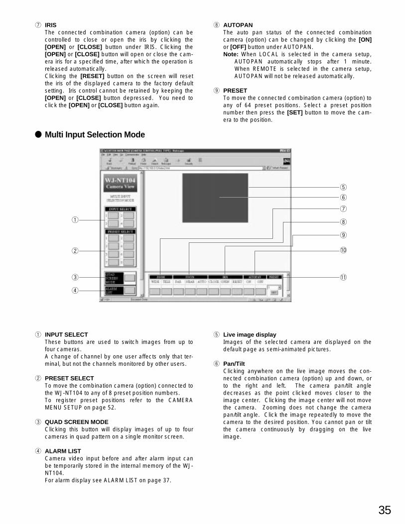
q INPUT SELECTThese buttons are used to switch the images of up to four cameras.A change of channel by one user affects only that terminal, but not the channels monitored by other users.
w QUAD SCREEN MODEClocking this button will display images of up to four cameras in quad pattern on a single monitor screen (see below).
e Live image displayImages of the selected camera are displayed on the default page as semi-animated pictures.
Quad Screen Mode [index4.html]
q
w
q RETURN TO MAIN PAGERestores Multi Input Selection mode.
w ALARM LISTCamera video input before and after alarm input can be temporarily stored in the internal memory of the WJ-NT104.For alarm display see ALARM LIST on page 37.
e Live image displayImages from up to four cameras are displayed.
e
32
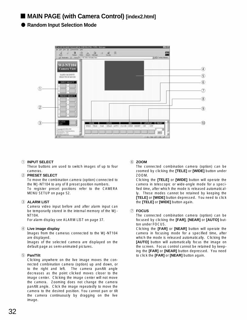
MAIN PAGE (with Camera Control) [index2.html]
Random Input Selection Mode
q
w
e
r
!0
t
o
i
u
y
q INPUT SELECTThese buttons are used to switch images of up to fourcameras.
w PRESET SELECTTo move the combination camera (option) connected tothe WJ-NT104 to any of 8 preset position numbers.To register preset positions refer to the CAMERAMENU SETUP on page 52.
e ALARM LISTCamera video input before and after alarm input canbe temporarily stored in the internal memory of the WJ-NT104.For alarm display see ALARM LIST on page 37.
r Live image displayImages from the cameras connected to the WJ-NT104are displayed.Images of the selected camera are displayed on thedefault page as semi-animated pictures.
t Pan/TiltClicking anywhere on the live image moves the con-nected combination camera (option) up and down, orto the right and left. The camera pan/tilt angledecreases as the point clicked moves closer to theimage center. Clicking the image center will not movethe camera. Zooming does not change the camerapan/tilt angle. Click the image repeatedly to move thecamera to the desired position. You cannot pan or tiltthe camera continuously by dragging on the liveimage.
y ZOOMThe connected combination camera (option) can bezoomed by clicking the [TELE] or [WIDE] button underZOOM.Clicking the [TELE] or [WIDE] button will operate thecamera in telescopic or wide-angle mode for a speci-fied time, after which the mode is released automatical-ly. These modes cannot be retained by keeping the[TELE] or [WIDE] button depressed. You need to clickthe [TELE] or [WIDE] button again.
u FOCUSThe connected combination camera (option) can befocused by clicking the [FAR], [NEAR] or [AUTO] but-ton under FOCUS.Clicking the [FAR] or [NEAR] button will operate thecamera in focusing mode for a specified time, afterwhich the mode is released automatically. Clicking the[AUTO] button will automatically focus the image onthe screen. Focus control cannot be retained by keep-ing the [FAR] or [NEAR] button depressed. You needto click the [FAR] or [NEAR] button again.
33
i IRISThe connected combination camera (option) can becontrolled to close or open the iris by clicking the[OPEN] or [CLOSE] button under IRIS. Clicking the[OPEN] or [CLOSE] button will open or close the cam-era iris for a specified time, after which the operation isreleased automatically.Clicking the [RESET] button on the screen will resetthe iris of the displayed camera to the factory defaultsetting. Iris control cannot be retained by keeping the[OPEN] or [CLOSE] button depressed. You need toclick the [OPEN] or [CLOSE] button again.
o AUTOPANThe auto pan status of the connected combinationcamera (option) can be changed by clicking the [ON]or [OFF] button under AUTOPAN.Note: When LOCAL is selected in the camera setup,
AUTOPAN automatically stops after 1 minute.When REMOTE is selected in the camera setup,AUTOPAN will not be released automatically.
!0 PRESETTo move the connected combination camera (option) toany of 64 preset positions. Select a preset positionnumber, then press the [SET] button to move the cam-era to the position.
34
Fixed Input Selection Mode
q PRESET SELECTTo move the combination camera (option) connected tothe WJ-NT104 to any of 8 preset position numbers.To register preset positions refer to the CAMERAMENU SETUP on page 52.
w ALARM LISTCamera video input before and after alarm input canbe temporarily stored in the internal memory of the WJ-NT104.For alarm display see ALARM LIST on page 37.
e Live image displayImages from the cameras connected to the WJ-NT104are displayed.Note: Other than the camera of the channel set cannot
be selected.
r Pan/TiltClicking anywhere on the live image moves the con-nected combination camera (option) up and down, orto the right and left. The camera pan/tilt angledecreases as the point clicked moves closer to theimage center. Clicking the image center will not movethe camera. Zooming does not change the camerapan/tilt angle. Click the image repeatedly to move thecamera to the desired position. You cannot pan or tiltthe camera continuously by dragging on the liveimage.
t ZOOMThe connected combination camera (option) can bezoomed by clicking the [TELE] or [WIDE] button underZOOM.Clicking the [TELE] or [WIDE] button will operate thecamera in telescopic or wide-angle mode for a speci-fied time, after which the mode is released automatical-ly. These modes cannot be retained by keeping the[TELE] or [WIDE] button depressed. You need to clickthe [TELE] or [WIDE] button again.
y FOCUSThe connected combination camera (option) can befocused by clicking the [FAR], [NEAR] or [AUTO] but-ton under FOCUS.Clicking the [FAR] or [NEAR] button will operate thecamera in focusing mode for a specified time, afterwhich the mode is released automatically. Clicking the[AUTO] button will automatically focus the video on thescreen. Focus control cannot be retained by keepingthe [FAR] or [NEAR] button depressed. You need toclick the [FAR] or [NEAR] button again.
q
w
e
o
r
i
u
y
t
35
q
Multi Input Selection Mode
q INPUT SELECTThese buttons are used to switch images from up tofour cameras.A change of channel by one user affects only that ter-minal, but not the channels monitored by other users.
w PRESET SELECTTo move the combination camera (option) connected tothe WJ-NT104 to any of 8 preset position numbers.To register preset positions refer to the CAMERAMENU SETUP on page 52.
e QUAD SCREEN MODEClicking this button will display images of up to fourcameras in quad pattern on a single monitor screen.
r ALARM LISTCamera video input before and after alarm input canbe temporarily stored in the internal memory of the WJ-NT104.For alarm display see ALARM LIST on page 37.
t Live image displayImages of the selected camera are displayed on thedefault page as semi-animated pictures.
y Pan/TiltClicking anywhere on the live image moves the con-nected combination camera (option) up and down, orto the right and left. The camera pan/tilt angledecreases as the point clicked moves closer to theimage center. Clicking the image center will not movethe camera. Zooming does not change the camerapan/tilt angle. Click the image repeatedly to move thecamera to the desired position. You cannot pan or tiltthe camera continuously by dragging on the liveimage.
u IRISThe connected combination camera (option) can becontrolled to close or open the iris by clicking the[OPEN] or [CLOSE] button under IRIS. Clicking the[OPEN] or [CLOSE] button will open or close the cam-era iris for a specified time, after which the operation isreleased automatically.Clicking the [RESET] button on the screen will resetthe iris of the displayed camera to the factory defaultsetting. Iris control cannot be retained by keeping the[OPEN] or [CLOSE] button depressed. You need toclick the [OPEN] or [CLOSE] button again.
i AUTOPANThe auto pan status of the connected combinationcamera (option) can be changed by clicking the [ON]or [OFF] button under AUTOPAN.Note: When LOCAL is selected in the camera setup,
AUTOPAN automatically stops after 1 minute.When REMOTE is selected in the camera setup,AUTOPAN will not be released automatically.
o PRESETTo move the connected combination camera (option) toany of 64 preset positions. Select a preset positionnumber then press the [SET] button to move the cam-era to the position.
w
e
r
t
!1
y
!0
o
i
u
36
u ZOOMThe connected combination camera (option) can bezoomed by clicking the [TELE] or [WIDE] button underZOOM.Clicking the [TELE] or [WIDE] button will operate thecamera in telescopic or wide-angle mode for a speci-fied time, after which the mode is released automatical-ly. These modes cannot be retained by keeping the[TELE] or [WIDE] button depressed. You need to clickthe [TELE] or [WIDE] button again.
i FOCUSThe connected combination camera (option) can befocused by clicking the [FAR], [NEAR] or [AUTO] but-ton under FOCUS.Clicking the [FAR] or [NEAR] button will operate thecamera in focusing mode for a specified time, afterwhich the mode is released automatically. Clicking the[AUTO] button will automatically focus the video on thescreen. Focus control cannot be retained by keepingthe [FAR] or [NEAR] button depressed. You need toclick the [FAR] or [NEAR] button again.
o IRISThe connected combination camera (option) can becontrolled to close or open the iris by clicking the[OPEN] or [CLOSE] button under IRIS. Clicking the[OPEN] or [CLOSE] button will open or close the cam-era iris for a specified time, after which the operation isreleased automatically.Clicking the [RESET] button on the screen will resetthe iris of the displayed camera to the factory defaultsetting. Iris control cannot be retained by keeping the[OPEN] or [CLOSE] button depressed. You need toclick the [OPEN] or [CLOSE] button again.
!0 AUTOPANThe auto pan status of the connected combinationcamera (option) can be changed by clicking the [ON]or [OFF] button under AUTOPAN.Note: When LOCAL is selected in the camera setup,
AUTOPAN automatically stops after 1 minute.When REMOTE is selected in the camera setup,AUTOPAN will not stop automatically.
!1 PRESETTo move the connected combination camera (option) toany of 64 preset positions. Select a preset positionnumber, then press the [SET] button to move the cam-era to the position.
37
ALARM FUNCTION
ALARM LIST WindowOn the Location bar, type http://192.168.0.10 (or IP address set for WJ-NT104)/almindex.html, or click the ALARM LISTbutton on the MAIN PAGE to display the ALARM LIST window. The window displays a list of alarm input dates, times andchannels. To display recorded alarm images, click the icon on the list.
q
w
e
r
t u i oy
q RETURN TO MAIN PAGEClick to return to the MAIN PAGE window.
w ALARM LISTDisplays a list of alarm IDs, dates, times and channelswhere alarm was generated. The list stores up to 100alarms. An icon at the right end of the line indicatesthat images have been recorded. Clicking the icon willdisplay the alarm images.
e Alarm image displayAlarm images are displayed in this space. The imagedisplay size is specified in the MODE SETUP window.(Images for which size 640 x 240 was selected, will befitted to the screen (640 x 480)).
r ALARM IMAGE CONTROL PANELFor frame-by-frame display of alarm images in CON-TINUOUS RECORDING mode. The control panel is notdisplayed in SINGLE FRAME RECORDING mode.
t GO TO FIRST FRAMETo jump to the first of a series of alarm images
y FRAME AT ALARM EVENTTo jump to the first image after an alarm in CONTINU-OUS RECORDING (BEFORE/AFTER ALARM) mode; tojump to the first of alarm images in CONTINUOUSRECORDING (AFTER ALARM) mode.
u GO TO LAST FRAMETo jump to the last of a series of alarm images
i PREVIOUS FRAMETo move one frame backward.
o NEXT FRAMETo move one frame forward.
38
Alarm activated Time base
Set delay time
Continuous recording
Alarm activated
Before continuous recording
After continuous recording
Time base
Alarm activated Single Frame Recording Time base
Set delay time
Differs depending on resolution and picture quality.Super Fine/Fine Normal/Rough
640 x 480 18 images 27 images640 x 240 43 images 61 images320 x 240 94 images 129 images160 x 120 255 images 255 images
Maximum number of recorded alarm images
ALARM RecordingThe WJ-NT104 records images before and after an alarm is activated and notifies the user of alarm input. Alarm imagescan be recorded in the following three modes:
Single Frame Recording modeWhen an alarm is received, the alarm image is captured and saved as a still image after the specified delay time.
• The delay time from receiving an alarm until capture of the alarm image can be specified in the range of 0 to 10 sec-onds in increments of 100 ms.
Continuous Recording [after alarm] modeWhen an alarm is received, the specified number of alarm images are captured and saved after the specified delay time.
• The delay time from receiving an alarm until capture of the alarm image can be specified in the range of 0 to 10 sec-onds in increments of 100 ms.
• The number of images to save can be set to between 1 and 18 (resolution 640 x 480).• A frame rate of 1/10, 1/5, 3/10, 1/2, 1, 2, 3, 5, or 10 can be selected.• If another alarm is received while recording an alarm, the on-going alarm processing is suspended and the new alarm
image is recorded with priority over the preceding one.
Continuous Recording [before/after alarm] modeImages before receiving an alarm are recorded at the preset frame rate and in the preset number of images. After analarm is activated, the specified number of images are continuously captured and saved.
• The total number of images to be saved before and after an alarm can be set to between 1 and 18 (resolution 640 x480).
• A frame rate of 1/10, 1/5, 3/10, 1/2, 1, 2, 3, 5, or 10 can be selected. (Frame rate 10 is not available for recordingbefore an alarm event.)
• If another alarm is received while recording an alarm, the on-going alarm processing is suspended and the new alarmimage is recorded with priority over the preceding one.
Note: This mode is valid only in Fixed Input Selectionmode is selected.
39
ALARM NOTICEThe WJ-NT104 can notify the user of an alarm event.The notice is sent either by Panasonic original protocol,e-mail (SMTP client) or a combination of both.
E-Mail NoticeMail is sent to the mail server using SMTP (Simple MailTransfer Protocol).16 mail addresses can be specified.
• Mail contents include the URL to access the alarmimage, date and time (hours, minutes, seconds) ofthe alarm, camera channel, and connection portID.
• If mail is not sent to the mail server before the settimeout, the mail is automatically deleted.
• In case of continuous recording [after/before], mailcontents are as follows:[Explanation]NT104:
Host name set by network setup (8 charactersmaximum). Default setting is WJ-NT104.
Date and time of alarm activation:Based on the time of the internal clock of theWJ-NT104.
Generating port:Port number of the alarm input/output terminalwhere an alarm is generated
Link to alarm image:Alarm image URL. In continuous recordingmode, the URL of the first image. In the follow-ing cases, accessing the URL may not displaythe alarm image.
q Alarm image is overwritten.(For the number of alarm images recorded seepage 38.)
w Alarm log is overwritten.(Up to 100 alarm logs can be recorded.)
e NT104 is restarted due to a change in settings.r Power is switched back on or the reset button
is pressed.Number of frames recorded:
Number of alarm images to be recorded.None in case Single Frame Recordingmode.
[Example]
If the PC on the alarm receiving end does not respondafter a specified number of connection retries because itis not powered up or for some other reason, the WJ-NT104 sends the alarm notice to another PC registeredas an alarm notice recipient.
Note
Panasonic Original Protocol Notice(option)This is a special protocol based on the TCP/IP protocolused to notify the users of an alarm.If an alarm is activated, an alarm notice is sent to thePC IP addresses set for the WJ-NT104 as alarm noticerecipients.
• To receive alarms, you need to install the specialalarm receiving software for the WJ-NT104 (option)on your PC. Your PC must be kept powered upand connected to the WJ-NT104 via a LAN.
• Up to 16 alarm notice destinations can be speci-fied for the WJ-NT104.
Alarm Image ReadoutRecorded alarm images can be read out by accessingthe alarm list (almindex.html) of the WJ-NT104.
<NUMBER OF FRAMES RECORDED>Total : 14Before : 4After : 10
40
SETUP PROCEDURES
How to Read ADMINISTRATOR SETUP PAGEOn the Location bar, type http://192.168.0.10/hwsetup.html to display the ADMINISTRATOR SETUP PAGE. To open theADMINISTRATOR SETUP PAGE, you need to enter your user ID and password. The default ID and password are[admin] and [nil (none)], respectively.
q
w
e
r
t
y
u
i
o
!0
[SET][SUBMIT] buttonClicking this button stores the settings made on theADMINISTRATOR SETUP PAGE in the WJ-NT104.The setting range of this button is indicated by theruled line that separates one item from another.The area showing the data within the range returnsto the original display when the button is clicked.The system is not restarted when this button ispressed.
[SET & REBOOT] buttonClicking this button stores the settings made onthis page in the WJ-NT104. Remember, however,that any recorded alarm data will be deleted.
q MODE SETUPTo set the default page when a file name is specified.Also set operation mode, image quality, and cameracontrol selection on this page.
w NETWORKTo select LAN/PPP and set the IP address, network,and default gateway.
e ALARMTo set alarm input ON/OFF, alarm image save mode,image overwrite YES/NO, number of images recorded,frame rate, and parallel I/O port (See page 37.).
r SERIAL PORTTo select RS-232C or RS-485 and set the communica-tion parameters.
t MODEMTo set the modem or TA to be used in the PPP connec-tion.
y USERUser authorization, user registration, user deletion.To register or delete a user table.
u HOSTTo set the address of the host that can be accessedwithout user certification.
i DATE/TIMETo set the internal clock of the device.
o CAMERA MENUTo set connected cameras (option) by remote control.
!0 RETURN TO MAIN PAGETo return to the MAIN PAGE window.
41
MODE SETUPOn the ADMINISTRATOR SETUP PAGE, click the MODE SETUP button to display the MODE SETUP window.Select the operation mode, image quality and camera control.
q VIDEO INPUT SELECTION MODESelect an operation mode for the camera displayed onthe monitor.The factory default setting is RANDOM INPUT SELEC-TION MODE.
w INPUT CHANNELThis item is available in FIXED INPUT SELECTIONMODE only. Select a channel for display on the moni-tor.The factory default setting is CH1
e VIDEO INPUT CHANNEL ON/OFFThis item is available in RANDOM INPUT SELECTIONMODE or MULTI INPUT SELECTION MODE only.
• RANDOM INPUT SELECTION MODEChannels set to OFF will not be displayed. Insequence mode, such channels are skipped.
• MULTI INPUT SELECTION MODEIf a channel set to OFF is selected, the frame rategoes up because images are captured by skippingthe channel set to OFF.
The factory default setting for channels are ON.
r INPUT CHANNEL SEQUENCEThis item is available in RANDOM INPUT SELECTIONMODE only.Set sequence operation to ON or OFF.The factory default setting is OFF.
t SEQUENCE INTERVALThis item is available in RANDOM INPUT SELECTIONMODE only. It defines the dwell time (time untilchangeover to the next channels) for sequence opera-tion.Dwell time can be set to a value between 1 and 30 sec-onds in increments of 1 second.The factory default setting is 2 Sec.
y MAIN PAGE DEFAULT INDEX FILE SELECTSet the window to be displayed when only a URL isspecified on the LOCATION bar.Note: If OTHERS is marked, the name specified next to
File name will open the MAIN PAGE window.
The factory default setting is index1.html
q
e
r
t
y
w
42
u RESOLUTIONSet a pixel number (resolution) for images from the WJ-NT104. The same value is applied for live images andalarm images.
The factory default setting is 320x240 pixels
i IMAGE QUALITYSet the image quality for images from the WJ-NT104.The same value is applied for live images and alarmimages.The factory default setting is FINE.
o FRAME SPEED CONTROL FOR PULL MODESet a frame speed for PULL mode.1 is the highest frame speed. The higher the number,the lower the frame speed.The factory default setting is 3.
!0 FRAME SPEED CONTROL FOR PUSH MODESet a frame speed for PUSH mode.This mode is supported by the Netscape Navigatorbrowser only.1 is the highest frame speed. The higher the number,the lower the frame speed.The factory default setting is 3.
!1 OUTPUT DATA RATE CONTROLSelecting a lower data rate reduces the possibility if anetwork traffic jam.The factory default setting is MAX.
u
i
o
!0
!1
43
!2 CAMERA CONTROL SELECTA camera control cable can be selected for each chan-nel.The factory default setting is COAXIAL.
!2
44
NETWORK SETUPOn the ADMINISTRATOR SETUP PAGE click the NETWORK button to display the NETWORK SETUP window.Select LAN/PPP, and set IP address, netmask, and default gateway.
q IP ADDRESS (LAN)Enter the IP address to be used with LAN.The factory default setting is 192.168.0.10.
w NETMASK (LAN)Enter the netmask to be used with LAN.The factory default setting is 255.255.255.0.
e DEFAULT GATEWAY (LAN)Enter the default gateway to be used with LAN.The factory default setting is 192.168.0.1.
r IP ADDRESS (PPP)Enter the IP address to be used with PPP.The factory default setting is 192.168.1.10.
t NETMASK (PPP)Enter the netmask to be used with PPP.The factory default setting is 255.255.255.0.
y DEFAULT GATEWAY (PPP)Enter the default gateway to be used with PPP.The factory default setting is 192.168.1.1.
u REMOTE IP ADDRESSUsed when PPP mode is on P to P ACCESS.Enter the IP address of the PC which calls and access-es the WJ-NT104. The PC's IP address must be set toObtain an IP automatically. The factory default settingis 192. 168. 1.11.
i PPP MODE• P to P ACCESS mode
To use this mode, match the IP address of the PCwith the address of the WJ-NT104.
• NETWORK ACCESS modeTo use this mode, match the address of the WJ-NT104 with the address of the PC. (Independent ofoutgoing and incoming calls)
The factory default setting is P to P ACCESS.
o HOSTNAMEEnter the host name.Alarm notice (e-mail) is sent in the host name specifiedhere. The host name you enter may be different fromthat entered for the domain settings (DNS).The factory default setting is WJ-NT104.
!0 NETWORK TYPESelect LAN or PPP.If PPP is marked, access via LAN is not possible.
q
w
e
r
t
y
u
i
o
!0
45
u
ALARM SETUPOn the ADMINISTRATOR SETUP PAGE, click the ALARM button to display the ALARM SETUP window.
q ALARM RECORDING/LOGSet the alarm recording function to ON or OFF.
w ALARM RECORDING MODESelect on alarm image recording mode.
e OVERWRITEWhen YES is marked, old alarm images are overwrittenby new alarm images.When NO is marked, new alarm images received afterthe limit for recording of alarm images has beenreached will not be recorded.
r NUMBER OF RECORDING FRAMESSet a number of images to be recorded before andafter an alarm is activated.
Note: Depending on the recording mode, this item isnot shown on the window.
t FRAME RATE OF RECORDING FRAMESet a frame rate range for recording before and afteran alarm is activated.Note: Depending on the recording mode, this item is
not shown on the window.
y ALARM RESETClicking this button clears the alarm images and alarmlog file saved in the memory.
u PARALLEL I/O PORTDesignate the Alarm Input/Output Port (Parallel I/Oport). The factory default setting is INPUT.Port number 8 can also be used for time adjustment. Ifa contact input is received within plus or minus 3 min-utes of the hour, the internal clock is set to the hour.
q
w
e
r
t
y
46
!6
!0 !1 !2 !3 !4
!5
!7
i PORT No.Same as the alarm terminal numbers on the rear panel
o ALARM FUNCTIONSet the alarm function to ON or OFF.
!0 CAMERA CHSpecify a camera channel to be selected when analarm is activated.
!1 CAMERA PRESETSpecify a preset position for the camera when an alarmis activated.This is valid only when a camera with preset function isconnected.
!2 DELAY TIME (per 100 msec)Set the time from activation of an alarm to the start ofrecording.
!3 ALARM CONTACTSelect between normally closed (NC) and normallyopen (NO) alarm contact.open: Accepts an NC alarm signalclose: Accepts an NO alarm signal
!4 SET buttonClicking this button saves the settings in the WJ-NT104.
!5 ALARM NOTICE (SMTP E-MAIL)To use the e-mail notice function, select YES.
!6 SERVER ADDRESSSpecify the address of the mail server to which mail issent directly from the WJ-NT104.
!7 SENDER NAMESet the name of a mail sender (up to 8, alphanumericcharacters lower case).
!8 Destination E-Mail addressSpecify the destination mail addresses of alarm noticerecipients. Up to 16 addresses can be set.
!9 Delete destination E-Mail addressesDisplays the list of e-mail addresses to receive alarmnotices. Clicking the DELETE button will delete anaddress from the list.
@0 ALARM NOTICE (Panasonic Protocol)If Panasonic's special alarm receiving software* isinstalled, mark YES to use the alarm notice function.* This software will be available in the near future as anoption.
@1 DESTINATION PORTSpecify 1818.
@2 RETRY NUMBER OF TIMESEnter the number of retries in the event that an alarmnotice is undeliverable.
@3 Destination IP addressSpecify the IP addresses of PCs to which an alarmnotice is to be sent. Up to 16 IP addresses can be set.
@4 Delete destination IP addressesDisplays the list of IP addresses to receive alarmnotices. Clicking the DELETE button will delete anaddress from the list.
i o
!8
!9
@0
@1
@2
@3
@4
47
SERIAL PORT SETUPOn the ADMINISTRATOR SETUP PAGE, click the SERIAL PORT button to display the SERIAL PORT SETUP window.Specify whether to use the RS-232C or RS-485 interface, and set the communication parameters.
q TYPE (RS-232C)Set up the RS-232C port usage. Select None, MODEM/TA, WJ-SX550A, WJ-FS616, WJ-DR200 or SerialThrough.The factory default setting is None.
w BAUD RATE (RS-232C)Set the baud rate for RS-232C to 300, 1200, 2400,4800, 9600, 14400, 19200, 38400, 57600, or 115200bps can be selected.The factory default setting is 4800 bps.It is recommended that 38400 bps be selected for a 56kbps modem, and 57600 bps when for a TA.
e DATA BIT (RS-232C)Set the data bits for RS-232C.The factory default setting is 8 bits.
r STOP BIT (RS-232C)Set the stop bit for RS-232C.The factory default setting is 1 bit.
t PARITY (RS-232C)Set the parity bit for RS-232C.The factory default setting is none.
y USE FLOW CONTROL (RS-232C)Set flow control for RS-232C.The factory default setting is none.
u TYPE (RS-485)Set up the RS-485 port usage. Select None or CAM-ERA + WJ-SX550A.The factory default setting is None.
i BAUD RATE (RS-485)Set the baud rate for RS-485 to 1200, 2400, 4800,9600, 19200, or 38400 bps can be selected.The factory default setting is 4800 bps.
o DATA BIT (RS-485)Set the data bits for RS-485.The factory default setting is 8 bits.
!0 STOP BIT (RS-485)Set the stop bit for RS-485.The factory default setting is 1 bit.
!1 PARITY(RS-485)Set the parity bit for RS-485.The factory default setting is NONE.
!2 X ON/X OFF (RS-485)Set flow control for RS-485 (X ON/X OFF).The factory default setting is OFF.
!3 DUPLEX MODESet the communication mode for RS-485.The factory default setting is FULL DUPLEX.
q
w
e
r
t
y
u
i
o
!0
!1
!2
!3
48
MODEM SETUPOn the ADMINISTRATOR SETUP PAGE, click the MODEM button to display the MODEM/TA SETUP window. Select themodem or TA (terminal adapter) for the PPP connection.
q MODEM MODELSSet a modem mode. Depending on the set value, themodem initializing command is issued. Select manualsetting or standard modem.The factory default setting is MANUAL SETTING.
w MODEM INITIALIZE COMMANDThis command is valid when MANUAL SETTING isselected for MODEM MODELS.Refer to the manual for the modem and set the initializ-ing command.
e LINE TYPESelect the type of telephone line to use. The factorydefault setting is TONE.
r LOCAL TELEPHONE NUMBERSet a telephone number for the WJ-NT104.
t DESTINATION TELEPHONE NUMBERSet the destination telephone numbers in case thealarm notice function is used.
y LOGON IDSet an ID code to log into the destination network whenmaking calls from the WJ-NT104.
u LOGON PASSWORDSet a password to log into the destination networkwhen making calls from the WJ-NT104.
i REDIAL (NUMBER OF TIMES/INTERVAL)In case of failure of the PPP connection, the number isredialed for the set number of times.The factory default setting is 2 retries at intervals of 60seconds.
o CONNECTION TIME (After alarm notice)Set a time to automatically disconnect the line after theWJ-NT104 accesses an alarm notice recipient. Thetime countdown starts with completion of alarm noticeprocessing. The factory default setting is 0 minute.
q
w
e
r
t
y
u
i
o
49
USER SETUPOn the ADMINISTRATOR SETUP PAGE, click the USER button to display the USER SETUP window. Use this window toregister or delete users.
q USER AUTHORIZATIONSet USER AUTHORIZATION to OFF or ON.Even if USER AUTHORIZATION is set to OFF, hostauthorization is necessary to access the pages exclu-sive to your network administrator, or to use the FTPfunction and PPP connection (to call the WJ-NT104).The factory default setting is OFF.
w USER REGISTRATIONSet USER NAME, PASSWORD, and ACCESS LEVEL.USER NAME and PASSWORD can be entered in upto 16 upper or lower case alphanumerics charactersand symbols. Select an ACCESS LEVEL 1 to 4. Tochange an already registered password and accesslevel, set them in the same way as to register a newpassword and access level, and then press the [SUB-MIT] button.For user authorization, refer to the ACCESS AUTHO-RIZATION on page 56.
e DELETE USERSelect a registered user and click the [DELETE] buttonto delete.The list of currently registered users can be viewed byclicking this pulldown list. The number in brackets isthe access level.
q
w
e
50
HOST SETUPOn the ADMINISTRATOR SETUP PAGE, click the HOST button to display the HOST SETUP window. Use this window toregister or delete hosts that can be accessed without user authorization.
q HOST AUTHORIZATIONSet HOST AUTHORIZATION to OFF or ON.The factory default setting is OFF.
w HOST REGISTRATIONSet a HOST IP ADDRESS and ACCESS LEVEL.Select an ACCESS LEVEL (1 to 4). To change analready registered password and access level, setthem in the same way as to register a new passwordand access level, and then press the [SUBMIT] button.For host authorization, refer to ACCESS AUTHORIZA-TION on page 56.
e DELETE HOSTSelect a registered HOST and press the [DELETE]button to delete.The list of currently registered hosts can be viewed byclicking this pulldown list. The number in brackets isthe access level.
q
w
e
51
DATE & TIME SETUPOn the ADMINISTRATOR SETUP PAGE, click the DATE/TIME button to display the CLOCK SETUP window. Use thiswindow to adjust the internal clock of the device.
q DATESet a date in the order of YY/MM/DD (for example,99/01/23 for January 23, 1999). The date is shownwhen this window is called on the screen.
w TIMESet a time in the order of HH:MM:SS (for example,12:03:45 for 3 minutes 45 seconds past 12 o’clock).Use the 24-hour system for time setting. The date isshown when this window is called on the screen.
q
w
52
CAMERA MENU SETUPOn the ADMINISTRATOR SETUP PAGE, click the CAMERA MENU button to display the CAMERA MENU SETUP win-dow.The CAMERA MENU SETUP function is available in RANDOM INPUT SELECTION MODE and FIXED INPUT SELEC-TION MODE, but not in MULTI INPUT SELECTION MODE.The cameras (option) can be set by remote control from this page.For the individual functions of the camera menu, refer to the operating instructions for the camera.
q MENU ON/OFFSelect ON or OFF for CAMERA MENU.
w ESCEscape from the currently selection and return to theprevious page of the CAMERA MENU.
e MOVE CURSOR - LeftTo move the cursor to the left. Use to change settingsor adjust levels.
r MOVE CURSOR - UpTo move the cursor up.
t MOVE CURSOR - DownTo move the cursor down.
y MOVE CURSOR - RightTo move the cursor to the right. Use to change settingsor adjust levels.
u SETTo execute the currently selected settings or to enter asubmenu of the CAMERA MENU.
i ALL RESETTo reset all camera settings to the factory defaults,clicking this button when the cursor is positioned on theCAMERA RESET in the SPECIAL MENU.
o RESETTo reset individual parameters to the factory defaults.Clicking this button will enter the SPECIAL MENU whenthe cursor is positioned on the SPECIAL in the menu.
!0 CAMERA SELECTTo select any of the cameras connected.
!0
e
w
q
r t y
o
u
i
53
UTILITY SOFTWARE
Network SetupSet IP address by using Utility Software provided to theunit and connecting it to the RS-232C port of the WJ-NT104.
ConnectionUse the COM1 port of the RS-232C for setting theaddress. Use a IBM-PC compactible computer inwhich either of the Windows 95/Windows 98/WindowsNT4.0 has been installed and the RS-232C port is pro-vided.Before installing the optional Utility Software, refer toReadme.txt contained in the Utility Software Disk 1.
q Turn ON the Mode Selector No. 7 in the WJ-NT104 frontpanel interior, and keep other switches turned OFF.
w Connect the WJ-NT104 to the PC.
e Click the Start button, point the Programs and thenWJ-NT104 Utilities, then Click Network Configu-ration.
r Setting the IP address: After entering the IP addressinto the [IP ADDRESS] of the dialog box in the rightside, press the [SET] button. If the NT 104 reply indi-cates both the reply command REI and the addressnumber entered (hexadecimal, 8-bit), for instance“REI:COA8000A” (if the address to be set is192.168.0.10), the address has been established nor-mally. If any wrong number is indicated, press the[SET] button again.
t Setting the network: After entering a set value in the[NETWORK] in the right dialog box, press the [SET]button. If the WJ-NT104 RESPONCE indicates boththe reply command REM and the address numberentered (hexadecimal, 8-bit), for instance“REM:FFFFFF00” (if the address to be set is255.255.255.0), the address has been established nor-mally. If any wrong number is indicated, press the[SET] button again.
y Setting the default gateway: After entering a set valuein the [DEFAULT GATEWAY] in the right dialog box,press the [SET] button. If the WJ-NT104 RESPONCEindicates both the reply command REG and theaddress number entered (hexadecimal, 8-bit), forinstance “REG:C0A80001” (if the address to be set is192.168.0.1), the address has been established nor-mally. If any wrong number is indicated, press the[SET] button again.
u When all the above-mentioned steps have been fin-ished, press the [EXIT] button.
PC
RS-232C crossover cable
WJ-NT104
9-pin D-sub connector(famale)
9-pin D-sub connector(famale)
1
2
3
4
5
6
7
8
Frame
1
2
3
4
5
6
7
8
FrameSheild
54
Confirmation of the set valuesAfter turning OFF all of the Mode Setup Switches in theWJ-NT104 front panel interior, reset the power switch.After conducting the resetting operation, the addressesentered come into effect.Confirm the communication by means of ping com-mands in the following procedures.
q Connect the WJ-NT104 to the PC. (See Page 10.) PC
10Base-Tcrossover cable
WJ-NT104
w Click the [START] button on the PC, and then point the [Programs]. The program menu appears. Choose [MS-DOSPrompt] out of the Programs and enter the following commands.
Pinging 192.168.0.10 With 32 bytes of date :
Reply from 192.168.0.10 : bytes = 32 time = 1ms TTL = 255Reply from 192.168.0.10 : bytes = 32 time = 1ms TTL = 255Reply from 192.168.0.10 : bytes = 32 time = 1ms TTL = 255Reply from 192.168.0.10 : bytes = 32 time = 1ms TTL = 255
C: \Windows>ping 192.168.0.10 (if the WJ-NT104 address is 192.168.0.10)
• If the WJ-NT104 replies as shown below, the address has been set normally.
• If the WJ-NT104 makes no reply and indicates as shown below, it is probable that the address has not been set at all.Attempt to set again.
• If the WJ-NT104 indicates as shown below, it is probable that the network setup of the PC is wrong. After correcting thesetup (for example, by setting the IP address to 192.168.0.2 and the sub network to 255.255.255.0), enter the ping com-mand again.
55
PC (DOS/V)
RS-232C crossover cable
WJ-NT104
Camera
Camera Menu SetupThis is software to control the camera menu of the WV-CS604A and CS654 (optional).This allows a user to open the menu of a camera connected to the WJ-NT104 with a coaxial cable and select preset posi-tion and other camera settings.
Operationq Connect the RS-232C port of the WJ-NT104 front panel and a PC with an RS-232C crossover cable.
w Turn ON both SW7 and SW9 of the mode of the WJ-NT104.
e Click the Start button, point to Programs and then WJ-NT104 Utilities, then Click Camera Setup.
r Select a channel in the Camera Select.
t Click the [MENU ON/OFF] button, and the Menu appears.Should it not appear, click the button repeatedly.
y Use [UP], [DOWN], [LEFT], [RIGHT], [ENTER], and [ESC] buttons to select the menu and execute a selected menu item.Refer to the Operating Instructions of each camera for the operation and setup of the menu.
u The [SPECIAL] button can be selected only when the cursor points the SPECIAL on the camera menu.
i When the [Camera Control] button is depressed, a panel for Coaxial Camera Control appears.PAN/TILT, ZOOM, and FOCUS control are selectable only in the “position setting menu.”
o To exit from the setup, press the [EXIT] button.
56
ACCESS AUTHORIZATION
Control of AccessAuthorizationControl the user’s access authorization in the followingprocedures.
If no access authorization is appliedIf neither user authorization nor host authorization areused (or are set to OFF) within a network, all the usersmay operate the following items at the access level 2.
• To control a camera and other equipment to beconnected to the WJ-NT104.
• To monitor live images.• To monitor alarm images and refer to log files.• To make access to the contents stored in the WJ-
NT104.* To make access to the administrator setup page of the
WJ-NT104 needs the account of the administrator.
If the access authorization is applied• Access authorization is applied in conformity with the
host access levels as designated in the HOST SETUPwindow. Since the IP Address of the host that hasmade a request to the WJ-NT104 is used for referringto the HOST SETUP window, the access level is deter-mined by the IP address of a proxy server, because theaccess is made via the proxy server.
• If an access is made from a PC that is not stored on theHOST SETUP window, the dialog box shown belowappears to request a user name and his/her passwordto be entered. The access level is determined whenboth the user name and the password are entered.
Access LevelThe users can be managed under the following fourlevels.More than one user can be designated to a same level.Commands to control equipment are given top priority,and the priority is not affected by the differences in thelevels. More than one administrator can be selected,and such a setup change can be made at any time.
Administrator Level (Level 1)• Access to and setting of the ADMINISTRATOR
SETUP PAGE can be effected.• The contents stored in the WJ-NT104 can be
rewritten by using an FTP (File Transfer Protocol).• Controlling of cameras and other equipment to be
connected to the WJ-NT104.• Monitoring of live image.• Monitoring of alarm image and reference to the log
file.• Access to the contents stored in the WJ-NT104.
INPUT Select and operation level(Level 2)
• Controlling of cameras and other equipment to beconnected to the WJ-NT104.
• Monitoring of live image.• Monitoring of alarm image and reference to the log
file.• Access to the contents stored in the WJ-NT104.
Monitoring only level (Level 3)• Monitoring of live image.• Monitoring of alarm image and reference to the log
file.• Access to the contents stored in the WJ-NT104.
Unauthorized level (Level 4)• No access is allowed to the WJ-NT104.
57
Host Setup WindowThe HOST SETUP window accepts maximum 16 termi-nal addresses. The default window contains nothing.The host IP address is written in a decimal style, like192.168.0.10, with a period (.) acting as separatingsymbol. No host names can be entered. The designa-tion of the host IP address in a form of “0.0.0.0” is treat-ed as ineffective one. Select one of Level 1 to 4 asaccess level.
RegistrationUsers of the administrator level (Level 1) alone can be registered to both the HOST SETUP and the USER SETUP windows.Both windows are established through their exclusive setting page.The factory default setting includes those users who correspond to the group of the user name = admin., password = nil(not necessary), and level = 1. The user “admin” allows the passwords to be changed, but does not accept the deletion ofa user and the changes of levels.
User Setup WindowThe USER SETUP window accepts maximum 16 users.User names and passwords should be composed ofthe maximum 16 characters, including majuscules andminuscules (identified from each other), numerals,and/or symbols. Select (enter) one of Level 1 to 4 asaccess level.
WJ-NT104 Authorized Function
CheckOperation Level
Host LevelAuthorization Process
Operation willbe Accepted
Operation willbe Denied
User LevelAuthorization Process
OperationRequest
OK
NG
NGOK
58
EXTEND FUNCTION
WJ-FS616 Video Multiplexer Control Connection(1) Connect between MULTISCREEN OUT on the rear of the WJ-FS616 and VIDEO IN 1 on the rear of the WJ-NT104(2) Connect the both of RS-232C Ports with a Crossover Cable.
• Fixed Input Selection ModeAvailables only the images from the MULTISCREEN OUT of the Video Multiplexer.
LINK RCV XMTOPERATE
Network Interface Unit WJ-NT104
1
1
1
1
PC
PC
PC
PC
WJ-NT104 (VIDEO IN1)WJ-FS616(MULTISCREEN OUT)
4
8
12
16
3
7
11
15
2
6
10
14
1
5
9
13
PUSH OPEN
16
POWER
LOCK
ON
OFF
ALARMMULTI
SCREENMULTISCREEN
SELECT
RESET SPOT SEQUENCE
VCRCAM
CAMERA/PRESET POSITION
Crossover CableRS-232C
PortRS-232C
Port
Setup(1) Click the [SERIAL PORT] button on ADMINISTRATOR SETUP PAGE to open the SERIAL PORT SETUP window.
Set the TYPE of RS-232C SETUP to WJ-FS616. Set all communication parameters to as same as WJ-FS616’s parameters.(2) Click the [MODE SETUP] button on ADMINISTRATOR SETUP PAGE to open the MODE SETUP window.(3) Set the VIDEO INPUT SELECTION MODE of OPERATION MODE SELECT to FIXED INPUT SELECTION MODE.
Control OperationSpecify http://192.168.0.10/fsindex.html in the Location bar, the following WJ-FS616 OPERATION VIEW window appears.
q
w
e
r o y !2
!3
!0 !1 iu t
59
q CAMERA SELECT (Left part of screen)To select a camera (camera 1 to camera 16) connect-ed to the WJ-FS616 Video Multiplexer. The selectedcamera is displayed in spot picture.
w PRESET SELECT (Left part of screen)To move the combination camera (option) connected tothe WJ-FS616 to any of 8 preset position number.
e ALARM LISTAny image before or after alarm input can be temporar-ily stored in the internal memory of the WJ-NT104. Foralarm display, see ALARM LIST (page 37).
r CAMERA SELECT (Bottom of screen)To select a camera (camera 1 to camera 16) connect-ed to the WJ-FS616. Select a camera number and thenclick the [SET] button to select a camera. The select-ed camera is displayed in spot picture.
t MULTISCREEN SELECTClicking this button repeatedly will switch the screen asfollows:
4 → 7 → 9 → 10 → 13 → 16→ 4 screen segments
y PRESET SELECT (Bottom of screen)To move the combination camera (option) connected tothe WJ-FS616 to any of 64 preset positions. Select apreset position number then click the [SET] button tomove the camera to the position.
u ALARM ALL RESETTo reset all alarms activated in the Video Multiplexer,and returns it to normal condition.
i PAN/TILTWhen this button is clicked, the connected combinationcamera (option) moves up and down, or to right andleft. Camera pan/tilt angle decreases as the point ofclick comes closer to the center of the button. Thecamera will not move when the button is clicked at thecenter. The camera pan/tilt angle does not change byzoom. It is not possible to continuously pan or tilt thecamera by kept clicking the button. Click the buttonrepeatedly until moving to the desired position.
o ZOOMThe connected combination camera (option) can bezoomed by clicking the [TELE] or [WIDE] button underZOOM.When the [TELE] or [WIDE] button is clicked on thescreen, the camera keeps telescopic or wide angleoperation for a specific time, then stops automatically.Such operation cannot be continued by keeping the[TELE] or [WIDE] button depressed. Click the [TELE]or [WIDE] button again.
!0 FOCUSThe connected combination camera (option) can befocused by clicking the [FAR], [NEAR] or [AUTO] but-ton under FOCUS.When the [FAR] or [NEAR] button is clicked on thescreen, the camera keeps focusing operation for a spe-cific time, then st ops automatically. When the [AUTO]button is clicked, the image on the display is automati-cally focused. Focusing cannot be continued by keep-ing the [FAR] or [NEAR] button depressed. Click the[FAR] or [NEAR] button again.
!1 IRISThe connected combination camera (option) can becontrolled to close or open iris by clicking the [CLOSE]or [OPEN] button under IRIS.When the [CLOSE] or [OPEN] button is clicked on thescreen, the camera iris is closed or opened for a spe-cific time, then stops automatically. When the [RESET]button is clicked, the camera iris on the display is resetto the factory default setting. Iris control cannot becontinued by keeping the [CLOSE] or [OPEN] buttondepressed. Click the [CLOSE] or [OPEN]] buttonagain.
!2 AUTO PANThe auto pan status of the connected combinationcamera (option) can be changed by clicking the [ON]or [OFF] button under AUTOPAN.Note: When LOCAL is selected in camera setup menu,
auto pan automatically stops in 1 minute. WhenREMOTE is selected in camera setup, auto pan willnot stop automatically.
!3 Image DisplayThe image output from MULTISCREEN OUT on thevideo multiplexer connected to the WJ-NT104 is dis-played.
60
WJ-SX550A Matrix Switcher Control Connections(1) Connect between the MONITOR OUTs on the rear of the WJ-SX550A and VIDEO IN 1 to 4 on the rear of the WJ-NT104.(2) Connect both of RS-232C Ports (on the WJ-SX550A and WJ-NT104) with a Straight Cable.
Or, connect between the CONTROL DATA port on the rear of the WJ-SX550A and RS-485 connectors on the rear of theWJ-NT104.
• Random Input Selection Mode• Set the VIDEO INPUT SELECTION MODE to RANDOM INPUT SELECTION MODE.• Unless a user changes channels, the last selected channel is used to continue transmission.• The image transfer speed is faster than the Multi Input Selection Mode.
O P E R A T E
Matrix Switcher WJ-SX550
LINK RCV XMTOPERATE
Network Interface Unit WJ-NT104
1
1
1
1
PC
PC
PC
PC
WJ-NT104WJ-SX550A
MON1 MON2
MON1 MON2
MON1 MON2
MON1 MON2
MonitorOut 1
MonitorOut 2
MonitorOut 3
MonitorOut 4
Straight Cable RS-232CPort
RS-232CPort
or RS-485Connector
CONTROLDATA Port
• Multi Input Selection Mode• Set the VIDEO INPUT SELECTION MODE to MULTI INPUT SELECTION MODE.• Multiple channels are periodically, even if different channel change requests come from two or more users.• The image transfer speed is slower than the Random Input Selection Mode.
O P E R A T E
Matrix Switcher WJ-SX550
LINK RCV XMTOPERATE
Network Interface Unit WJ-NT104
1
2
3
4
PC
PC
PC
PC
WJ-NT104WJ-SX550A
MonitorOut 1
MonitorOut 2
MonitorOut 3
MonitorOut 4
Straight Cable RS-232CPort
RS-232CPort
or RS-485Connector
CONTROLDATA Port
MON1
MON2
MON3
MON4
61
SetupSet the TYPE of RS-232C or RS-485 to WJ-SX550A, using the SERIAL PORT SETUP window. Also set the other commu-nication parameters to the same values as set in the matrix switcher. (For further details, refer to the Operation Manual forthe Matrix Switcher WJ-SX550A.) The MATRIX SW CONFIGURATION page appears when the link to [MATRIX SW CON-FIGURATION page] at the end of the SERIAL PORT SETUP window is clicked.
q PASSWORDSet the same value as set for the matrix switcher in 5numerals.
w VIDEO-INPUT NUMBER AND MONITOR-OUT CHAN-NEL SETUPSet a channel number for the monitor output of the
matrix switcher WJ-SX550A to be connected to thevideo input connector on the network interface unit WJ-NT104. When WJ-NT104 VIDEO IN is selected fromthe table set by this setup procedure, there will be thesame status as when a monitor compatible with theSX550A is selected.
Control OperationThe matrix switcher (WJ-SX550A) control windows are available when http://192.168.0.10/sxindex.html is specified forURL.
q
w
e
r
ti y u !1o !0
q
w
!2
62
q VIDEO IN (WJ-NT104)To select any of the 4 video inputs of the network inter-face unit to display the desired image. Set the matrixswitcher monitor outputs corresponding to the networkinterface unit video inputs, referring to the MATRIXSWITCHER CONFIGURATION page on page 61.Video switching takes place according to the mode setby the operating mode procedures. Refer to [MAINPAGE AND CONTROLS] at page 25 for operatingmode specifications and to [MODE SETUP] at page 41for the setting procedures.
w CAMERA SELECT (Left part of screen)To select a camera (camera 01 to camera 08) connect-ed to the WJ-SX550A matrix switcher. The selectedcamera is displayed on the display that is correspond-ing to the input selection mode previously set.
e PRESET SELECT (Left part of screen)To move the combination camera (option) connected tothe WJ-SX550A to any of 8 preset position number.
r ALARM LISTAny image before and after alarm input can be tem-porarily stored in the internal memory of the WJ-NT104.For alarm display, see ALARM LIST (page 37).
t CAMERA SELECT (Bottom of screen)To select a camera (CAMERA 1 TO CAMERA 128) con-nected to the WJ-SX550A. Select a camera numberand then click the [SET] button to select a camera.The selected camera is displayed on the display that iscorresponding to the input selection mode previouslyset.
y PRESET SELECT (Bottom of screen)To move the combination camera (option) connected tothe WJ-SX550A to any of 64 preset positions. Select apreset position number then click the [SET] button tomove the camera to the position.
u ALARM ALL RESETTo reset all alarms activated in the Matrix Switcher, andreturns it to normal condition.
i Image DisplayThe image output from the matrix switcher connectedto the NT104 is displayed. Set the matrix switchermonitor outputs corresponding to the network interfaceunit video inputs, referring to [MATRIX SWITCHERCONFIGURATION] at page 61.
o PAN/TILTWhen a point on the live images is clicked, the con-nected combination camera (option) moves up anddown, or to right and left. Camera pan/tilt angledecreases as the point of clock comes closer to thecenter of the live images. The camera will not movewhen the live image is clicked at the center. The cam-era pan/tilt angle does not change by zoom. It is notpossible to continuously pan or tilt the camera by drag-ging on the live image. click on the image repeatedlyuntil moving to the desired position.
!0 ZOOMThe connected combination camera (option) can bezoomed by clicking the [TELE] or [WIDE] button underZOOM.When [TELE] or [WIDE] button is clicked on thescreen, the camera keeps telescopic or wide-angleoperation for a specific time, then stops automatically.Such operation cannot be continued by keeping the[TELE] or [WIDE] button depressed. Click the [TELE]or [WIDE] button again.
!1 FOCUSThe connected combination camera (option) can befocused by clicking the [FAR], [NEAR] or [AUTO] but-ton under FOCUS.When the [FAR] or [NEAR] button is clicked on thescreen, the camera keeps focusing operation for a spe-cific time, then stops automatically. When the [AUTO]button is clicked, the image on the display is automati-cally focused. Focusing cannot be continued by keep-ing the [FAR] or [NEAR] button depressed. Click the[FAR] or [NEAR] button again.
!22 IRISThe connected combination camera (option) can becontrolled to close or open iris by clicking the [CLOSE]or [OPEN] button under IRIS.When the [CLOSE] or [OPEN] button is clicked on thescreen, the camera iris is closed or opened for a spe-cific time, then stops automatically. When the [RESET]button is clicked, the camera iris on the display is resetto the factory default setting. Iris control cannot becontinued by keeping the [CLOSE] or [OPEN] buttondepressed. Click the [CLOSE] or [OPEN] buttonagain.
!33 AUTO PANThe auto pan status of the connected combinationcamera (option) can be changed by clicking the [ON]or [OFF] button under AUTOPAN.Note: When LOCAL is selected in camera setup menu,
auto pan automatically stops in 1 minute. WhenREMOTE is selected in camera setup, auto pan willnot stop automatically.
LINK RCV XMTOPERATE
Network Interface Unit WJ-NT104
R A M
PUSH OPEN PUSH OPEN
AV Disc Recorder WJ-DR
REMOTE
OPERATE
ALARM
RESET
REC
DISC
ALARMREC
DISC CONTROL
PC
PC
PCWJ-DR200
WJ-NT104
CAMERA 1
CAMERA 2
CAM1
CAM1
CAM1
(VIDEO OUT)
Crossover CableRS-232C
PortRS-232C
Port
63
LINK RCV XMTOPERATE
Network Interface Unit WJ-NT104
R A M
PUSH OPEN PUSH OPEN
AV Disc Recorder WJ-DR
REMOTE
OPERATE
ALARM
RESET
REC
DISC
ALARMREC
DISC CONTROL
DR
PC
DR
PC
DR
PC
WJ-DR200 WJ-NT104 (VIDEO IN 1)CAMERA 1
CAMERA 2
(VIDEO OUT)
Crossover Cable RS-232CPort
RS-232CPort
WJ-DR200 AV Disk Recorder Control Connections• Fixed Input Selection Mode(1) Connect CAMERA 1 and 2 to the VIDEO IN A and B on the rear of the WJ-DR200.(2) Connect between the VIDEO OUT on the rear of the WJ-DR200 and VIDEO IN 1 on the rear of the WJ-NT104.(3) Connect the both of RS-232C Ports (on the WJ-DR200 and WJ-NT104) with a Crossover Cable.
• Available only the images from the VIDEO OUT on the rear of the AV Disc Recorder.
• Random Input Selection Mode(1) Connect CAMERA 1 and 2 to the VIDEO IN 1 and 2 on the rear of the WJ-NT104.(2) Connect between the VIDEO OUT 1 and 2 on the rear of the WJ-NT104 and the VIDEO IN A and B of the WJ-DR200.(3) Connect between the VIDEO OUT of the WJ-DR200 and the VIDEO IN 3 of the WJ-NT104.(4) Connect the both of RS-232C Ports (on the WJ-DR200 and WJ-NT104) with a Crossover Cable.
• Set the VIDEO INPUT SELECTION MODE to RANDOM INPUT SELECTION MODE.• Enables camera control, if the cameras are connected to VIDEO IN on the rear of the WJ-NT104. (Requires to cus-
tomize the WJ-DR200 OPERATION VIEW window)• Unless a user changes channels, the last selected channel is used to continue transmission.
• Multi Input Selection Mode(1) Connect CAMERA 1 and 2 to the VIDEO IN 1 and 2 on the rear of the WJ-NT104.(2) CONNECT BETWEEN THE VIDEO OUT 1 and 2 on the rear of the WJ-NT104 and the VIDEO IN A and B of the WJ-DR200.(3) Connect between the VIDEO OUT of the WJ-DR200 and the VIDEO IN 3 of the WJ-NT104.(4) Connect the both of RS-232C Ports (on the WJ-DR200 and WJ-NT104) with a Crossover Cable.
• Set the VIDEO INPUT SELECTION MODE to MULTI INPUT SELECTION MODE.• Availables camera control, if the cameras are connected to VIDEO IN on the rear of the WJ-NT104. (Requires tot cus-
tomize the WJ-DR200 OPERATIONVIEW window)
• Multiple channels are periodically,even if different channel changerequests come from two or moreusers.
LINK RCV XMTOPERATE
Network Interface Unit WJ-NT104
R A M
PUSH OPEN PUSH OPEN
AV Disc Recorder WJ-DR
REMOTE
OPERATE
ALARM
RESET
REC
DISC
ALARMREC
DISC CONTROL
PC
PC
PCWJ-DR200
WJ-NT104
CAMERA 1
CAMERA 2
CAM1
CAM2
DR200
(VIDEO OUT)Crossover Cable RS-232C
PortRS-232C
Port
64
SetupSet the TYPE of RS-232C to WJ-DR200, using the SERIAL PORT SETUP window. Also set the other communication para-meters to the same values as set in the AV Disk Recorder (WJ-DR200). (For further details, refer to the Operation Manualfor the AV Disk Recorder WJ-DR200.)
Control OperationThe WJ-DR200 OPERATION VIEW windows are available when http://192.168.0.10/drindex.html is specified for URL.
q ALARM REC STANDBYTo Toggle the alarm recording enabled and disabledon the WJ-DR200 AV disc recorder.
w INDEXTo search the disk for recorded frames. The WJ-DR200 Record List window appears on the display asshown below. Click the [REFRESH] button in the win-dow to renew the record corresponding with the recorddisplay on the image display position, and then clickthe specific number to play back the selected frames.To exit from the search mode, click the [STOP] button.
This button also toggles the record display in list andthumbnail.WHILE the recorded list is displayed on the image dis-play position, it is also available to search the disk assimilar as the operation of the WJ-DR200.Refer to the Operation Instructions for further operationdetails.
q
w
e
r
tyu
i
o !4
!9
!0 !5 !1 !6 !2 !7 !3 !8
65
e FINDTo directly specify and play back a recorded frame.
r UP/Next FrameClick in paused playback to advancE the playbackoperation one step to the next frame.It also moves the cursor up one line while the recordedlist or thumbnail is displayed on the screen.
t LEFT/Prev RecTo move the playback operation back one step to theprevious record.It also moves the cursor to the left while the recordedlist or thumbnail is displayed on the screen.
y SETWhen it is clicked during list display or thumbnail dis-play, the selected frames begin to play back.In frame search, click this button to apply the enteredvalue.
u RIGHT/Next RecTo move the playback operation one step to the nextrecord.It also moves the cursor to the right while the recordedlist or thumbnail is displayed on the screen.
i DOWN/Prev FrameClick in paused playback to move the playback opera-tion back one step to the previous frame.It also moves the cursor down one line while therecorded list or thumbnail is displayed on the screen.
o REWTo playback the record in search backward.
!0 REVERSE PLAYTo play back frames in reverse order.
!1 STOPClicking this button will terminate all modes of opera-tion, such as recording, playback, and setting.
!2 PLAYTo play back frames in forward order.
!3 FFTo playback the record in search forward.
!4 RECTo start recording in the previously defined mode.
!5 PAUSEClick to temporarily pause playback.
!6 TL MODE - (minus)Clicking this button in playback will increase the play-back speed.Clicking it in paused playback will decrement the play-back channel (or camera ID). to play back the select-ed channel, click the [PLAYBACK SELECT] button.
!7 TL MODE + (plus)Clicking this button in playback will decrease the play-back speed.Clicking it in paused playback will increment the play-
back channel (or camera ID). To play back the select-ed channel, click the [PLAYBACK SELECT] button.
!8 PLAYBACK SELECTClicking this button after selecting the input channelwith the (+) or (–) button will start playback of therespective channel.
!9 Image DisplayThe images that are previously set in the input select isdisplayed.
Note: The buttons on the screen will be applied similar tothe WJ-DR200’s buttons.Refer to the Operating Instructions of the WJ-DR200 forfurther details.
66
CONTENTS UPLOAD
Contents can be uploaded by means of an FTP (FileTransfer Protocol). The following describes how to uploadcontents produced by using a PC.
Uploading a FileUpload contents produced by using a PC in the follow-ing procedures.
q Click the [Start] button, point to Programs, and thenclick MS-DOS Prompt to open on MS-DOS window.
w Enter an FTP command on the MS-DOS window andstart the FTP. Then, enter the address of the WJ-NT104IP address.C:\CONTENTS>FTP 192.168.0.10
e In response to the input request for a user account, login the user at the administrator level (Level 1).User (192.168.0.10 : (none)) : admin
r Enter a password.Password:
t After finishing the log-in operation, enter “bin” to selecta binary transmission mode.ftp>bin
y Enter a put command to upload the file.ftp>put upload.html
u After finishing the transmission, enter “quit” to exit fromthe FTP.ftp>quit
NotesIf transmitting more than one file, enter “prompt” torelease the interactive mode. Then, enter a wild cardsymbol (for example, “*”) in the input portion of the file-name of the input command, thereby enabling to trans-mit more than one file at a time.
ftp>promptInteractive mode offftp>mput *.html
Content Storage Memory• Content files such as HTML that have been uploaded
by means of the FTP are stored in the flash ROM of theWJ-NT104. Hence, they are protected from erasurewhen the power switch is turned off. However, they arereturned to an initial state during version-up operationor if reset after turning on the Mode Setup Switch “2” ofthe WJ-NT104. Be sure to back up the files beforeattempting to conduct such operations.
• No directories can be prepared in the content memoryinterior.
• Majuscules and minuscules are discriminated in thecontent file name.
Storing capacity: A total of about 1.5 MbytesNumber. of files to be stored: Maximum 650
* The above figures are subject to change, depend-ing on file sizes and memory usage.
Description
To get a frame of a new image.Parameter CH:
Fixed Input, Random Input mode:Ignored (or can be omitted)Multi Input mode: Essential
Push mode image get command for NetscapeParameter CH:
Fixed Input, Random Input mode: Ignored (orcan be omitted)Multi Input mode: Essential
Channel for converting %c: Essential
Name of files to be converted: Essential
67
Parameter
1-4
1-4
1-4
File name
Parameter name
CH
CH
CH
FILE
URL
/cgi-bin/camera
/cgi-bin/push
/cgi-bin/chconv
CGI item
Pull modeimage get
Push modeimage get
Channel No.conversion
(See page 73.)
CONTROL BY HTML DESCRIPTION
Image display, camera operation, and alarm image display can be effected on WWW browser by means of commandsdescribed in the HTML (Hyper Text Mark-up Language) file. The WJ-NT104 employs CGI (Common Gateway Interface) tocarry out these functions. When using a function, the following syntax is used.
z This is the function to call new images by means of Javascript.
x This is a time interval (msec) to be converted by %i, requesting a new image in a pull mode. (See Page 73.) The pagenumber of the argument is added for nullifying the cache.
x
file name
68
HTML Sample File [nsmainview1.html]
<HTML><HEAD></HEAD><BODY BGCOLOR=”#FFFFCC”>
<CENTER><SCRIPT LANGUAGE=”JavaScript”>width=%Wheight=%HmyDate = new Date();document.write(“<IMG SRC=/cgi-bin/push?CH=%c&PAGE=”+myDate.getTime()+”WIDTH=”+width+” HEIGHT=”+height+ “ VSPACE=5></A>”);</SCRIPT>
</CENTER></BODY>
</HTML
z
z This is to request to get a new image in a push mode. The page number of the argument is added for nullifying the cache.
Camera Operation CGI functions related to the camera operation
The WV-CS604 and CS654 (optional) can be operated by using the following commands.The following commands can be selected at a time. (Example: PAN and TILT can be operated in a combined manner.)
CGI item URL Parameter name Parameter Parameter
Cameracontrol
/cgi-bin/camctrl CHSEL 1-4 Selecting a video channelRandom Camera mode: EnabledMulti Camera/Fixed Camera mode: Disabled
CH 1-4 Selecting a camera to be controlled in the MultiCamera modeRandom Camera and Fixed Camera modes areineffective even if they are selected, and com-mands are applied only to the CH displayed.
PRESET 0-64 0: Calling a home position1 to 64: Calling a preset position
PAN –10-10 PAN & STOPNegative: Left, Positive: RightThe moving distance is in proportion to theirabsolute values.
TILT –10-10 TILT & STOPNegative: Down, Positive: UpThe moving distance is in proportion to theirabsolute values.
ZOOM –10-10 ZOOMNegative: Wide, Positive: TeleZooming ratio is in proportion to their absolute val-ues.
ATPAN on, off Turning ON/OFF of auto pan
AF on Auto Focus
FOCUS –10-10 FocusNegative: Near, Positive: FarFocusing ratio is in proportion to their absolute val-ues.
IRIS
FILE
–10-10 IrisNegative: Close, Positive: Open, 0: ResetThe iris-opening ratio is in proportion to theirabsolute values.If a user wants to change the display on thescreen after camera controlling operation, specifythe name of a file to be displayed. No displayedscreen is changed, if omitted.
</SCRIPT></CENTER><HR><FONT SIZE=2 COLOR=BLUE>Copyright © 1998-1999Matsushita Communication Industrial Co., Ltd.<BR>All rights reserved.</FONT></BODY></HTML>
z If selecting a channel in the Random Input Selection mode, set a value to the ARGUMENT CHSEL and carry out the CGIfunction (camctrl).
x If selecting a channel in the Multi Input Selection mode, the function of “chconv” is used to make known the channel selec-tion to the mainview.html and camctrl.html.
c This is a link to Quad Screen display. The link button for the four-screen concurrent display is indicated only in the MultiInput Selection mode.
z This changes the zooming ratio of the camera (optional) in the channel designated by the %c (Page 73).Negative values indicate TELE and positive ones indicate WIDE.
x This changes the focusing ratio of the camera (optional) in the channel designated by the %c (Page 73).Negative values indicate FAR and positive ones indicate NEAR. AF is the abbreviation of “auto focus.”
c This changes the iris-opening/closing ratio of the camera (optional) in the channel designated by the %c (Page 73).Negative values indicate OPEN and positive ones indicate CLOSE. The value zero (0) indicates resetting.
v This selects ON/OFF of the auto pan of the camera (optional) in the channel designated by the %c (Page 73).
b This calls a preset position (1 to 64) of the camera (optional) in the channel designated by the %c (Page 73).
z
x
c
v
b
Alarmimage control(See page 73.)
72
Description
Alarm Operation CGI functions concerning alarming
Alarm images and log files recorded in the WJ-NT104 can be referred to by using the following commands.
CGI item URL Parameter name Parameter
Alarm logfile list
/cgi-bin/almlog TARGETI HTMLframe name
Alarm image display target name(A new window is produced, if the command isomitted.)
/cgi-bin/almctrl
TARGETC HTMLframe name
Alarm image control frame target name(The control frame cannot be used, if the com-mand is omitted.)
BGCOLOR 000000-FFFFFF
Background color(Default color of the browser, if the command isomitted.)(hexadecimal, 6-bit or HTML color name)
IMGHTML file name HTML file name for the alarm image frame(Direct display of images, if the command is omit-ted.)
z When the button is clicked, the first frame is displayed.
x When the button is clicked, frame immediately after alarm is displayed.
c When the button is clicked, the last frame is displayed.
v When the button is clicked, the image of the preceding frame is displayed.
b When the button is clicked, the image of the next frame is displayed.
Substitution Character Strings in HTTP ServerParameters can be described in HTML files by means of substitute characters as described below.
Ordinary HTML file getWhen an HTML file containing the following substitute characters is transmitted to a client through the HTML protocol, it istransmitted with the substitute characters unconditionally converted into internal parameters.Any characters that begin with % but are not substitute ones are displayed as they are (for example, %k is displayed as%k).If a user wants to transmit a character string that are same as substitute one, one of the following methods can be chosen.(for example, %m / %m)
Description
Version
Substitute character
Action mode
Camera channel
%m
%c
Pull interval %i
In the Random Input Selection mode, %m is substituted with 0, and in the 1ch staticmode, it is substituted with 1.
DescriptionItem Substitute character
Camera channel %c Number (1 to 4) of channel for argument parameter
%v
In the Multi Input Selection mode, %m is substituted with 2.Channel (1 to 4) selected in the Random Input Selection mode.Camera channel is not fixed in other modes.
Call interval (msec.) in the pull mode (decimal).
Live imagedata size
%w%h
Live imagedisplay size
%W
%H
Both %w and %h indicate the width and height of current live image, respectively.Both %W and %H indicate the width and height with which the above-mentioned liveimage is displayed.
Firmware Version
Ether address %e Ether address (MAC address)00-00-00-00-00-00 type (hexadecimal, 2 x 6-bit)
/cgi-bin/chconvThe substitute characters other than %c are same as those in the case of normal HTML file get. This substitute character isused to designate a channel number in the Multi Input Selection mode.
74
Item Description
Next frame number
Substitute character
Log number
First frame number
%l
%h
Immediatelyafter alarm
Frame number
%a
Log number 0000-FFFF (hexadecimal, 6-bit)
%n
First frame number of an alarm image for specified log number (LNO). Normally, 00.
Frame number immediately after receiving an alarm for specified log number (LNO). 00 -FF (hexadecimal, 2-bit)
Last frame %t Last frame number of an alarm image for specified log number (LNO). 00 - FF (hexadeci-mal, 2-bit)
Specified frame %c Same as the value of argument FNO. 00 - FF (hexadecimal, 2-bit)
Value of preceding argument FNO. If the FNO represents the first frame number (= %h)of the specified log number (LNO), the value of the FNO is applied. 00 - FF (hexadeci-mal, 2-bit)
Preceding framenumber
%p Value of preceding argument FNO. If the FNO represents the last frame number (= %t)of the specified log number (LNO), the value of the FNO is applied. 00 - FF (hexadeci-mal, 2-bit)
Alarm imagedisplay size
%W%H
Both %W and %H represent the width and the height at which an alarm image of thespecified log number (LNO) is displayed, respectively.(%w, %h, %W, %H ) = (640, 480, 640, 480) or (640, 240, 640, 480) or (320, 240, 320,
240) or (160, 120, 160, 120)
cgi-bin/almctrlNo substitute characters in the case of normal HTML file get can be used.This can be used in the same manner as the HTML file get ones.
For example, the first alarm number of the specified log is described as /alm%l_%h.jpg in the HTML.
75
TROUBLESHOOTING
No power is supplied(No operation indicator is lit on).
Prior to having the unit repaired, check the following items.
• Is an AC adapter (optional) connected to the DC power connector in the WJ-NT104 rearpanel?
No access from the browser.• If connected through a modem
• Is the modem power switch turned ON?• Is the modem cable connected to the RS-232C connector of the rear panel?• Is network-type PPP in the Network Setup mode chosen (refer to the CD-ROM).
• In the case of LAN connection • Is a 10Base-T cable connected to the Ethernet connector of the rear panel?
• Is the link indicator of the front panel lit on?If it is not lit on, the unit is not correctly connected to the LAN or the network is not correctlyconnected. Check for any poor contact or disconnection of the cable.
• Is the WJ-NT104 IP address correctly set? (Refer to the CD-ROM.)
• Is the wrong IP address accessed? (Refer to the CD-ROM.)If making access from Windows95 or UNIX, confirm the connection in the following manner.>ping [IP address set in the WJ-NT104]If the WJ-NT104 gives a reply when the above command is entered, the unit is operatingcorrectly. If it gives no reply, follow the subsequent setting procedures:
(1) Make initialization by referring to the “mode setting,” and set the IP address to192.168.0.10.
(2) Retry to set the IP address to a desired value while referring to the section describingthe connection to the global network (in the CD-ROM).
• Does the selected IP address not overlap with other instrument? (Refer to the CD-ROM.)• Does the setting address not contradict with a network sub-network of the system in which
it has been set?[If the WJ-NT104 and a client PC are connected to the same sub-network]
• Are the WJ-NT104 and a client PC connected to a common sub-network?Or, is “using a proxy server” not selected in the browser?It is recommended to select the WJ-NT104 address as one “not using a proxy server” ifmaking access to the WJ-NT104 within the same sub-network.
[If the WJ-NT104 and a client PC are connected to different sub-networks]• Is the selected value of the WJ-NT104 default gateway not wrong?
Any image is not displayed. • Are power switches for a camera and other instruments turned ON?
Images are not updated. • Images may not be updated or camera control may become out of order, depending on thetypes and versions of the WWW browser adopted. It is recommended, therefore, to employthe Netscape Navigator version 4.04 or higher or Internet Explorer 4.0 or higher.
• Display of images may sometimes be suspended, if the network is crowded or access tothe WJ-NT104 is concentrated. In such a case, press the [Reload] button of the browser tomake request to get image.
The certification window that wasopened when displaying a defaultpage cannot be closed.
• Enter correct user name and password.If the correct user name and password are unavailable, repeatedly press the [ESC] buttonon the screen. If a series of more than one input is effectively accepted, the certificationwindow is not displayed again.
The image rate of the modem con-nected is very slow.
• Check the actual data transfer rate of the circuit between the modems.The image rate may be improved in some cases, if the bit rate of serial setting is set to avalue near the actual data transfer rate.
No HTML files are displayed. • Check the contents of the HTML file.No HTML files are displayed, if they are wrongly described or are broken.HTML files may be broken, if they have not been fully initialized. Initialize the files again byturning on the Mode Setup Switch No. 2 of the WJ-NT104.
Images cannot be saved. • Check the image-displaying mode. No images can be saved in the push mode.
Image get is abnormally delayed, orPC does not react at all.
• Microsoft has publicized that the Windows 95 may develop a trouble if it is operated formore than 50 consecutive days. It is recommended to reset your PC once a week.
Live images cannot be updated.Alarm images cannot be updated.
• Image request may not be made to the WJ-NT104, because data are called from the cacheof the PC. Should this phenomenon occur frequently, it is recommended to set the browserin the following manner:[In the case of Netscape Navigator]
Set to zero Kbyte the memory cache and disk cache in the category [DETAIL-CACHE] ofthe Menu [SETTING].
[In the case of Internet Explorer]Change the “Checking the latest version of pages stored” to “Checking whenever apage is displayed” in the item “Setting an Internet temporary file” of the “InternetOptions.”
Symptoms Check items
To be used when connecting to the LAN. Thiscan be connected to a hub for 10Base-T or10/100 BASE-TX or a switching hub for10Base-T or 10/100 BASE.
Available image modes
Ethernet hub orSwitching hub
76
INSTRUMENTS TO BE CONNECTED
Network System
CCTV Camera (option)
Monitoring Browser
Instrument Outline
ModemTo be used when connecting to a telephonecircuit (POTS).
Terminal adapterTo be used when connecting to an ISDN cir-cuit.
Terminal adapterTo be used when connecting to an ISDN cir-cuit.
Browser Type
Netscape Navigatorversion 4.04 or higher
Push mode under the Netscape systemPull mode under the Java Script system
Internet Explorer 4.0 or higher Pull mode under the Java Script system
Instrument
CCTV camera
Available image modes
Recommend: Panasonic-made
Combination cameraWV-CS604, WV-CS654
Outline
Camera equipped with the function to outputimages complying with the NTSC standard.
Coaxial communication type. Both pan/tilthead control and lens control can be used viaLAN from a remote PC.
Power Source: 12 V DC, 800 mAAmbient Operating Temperature: –10°C - +50°C (14°F - 122°F)Ambient Operating Humidity: Less than 90 %Dimensions: 210 (W) x 44 (H) x 350 (D) mm
8-1/4” (W) x 1-3/4” (H) x 13-3/4” (D)Weight: 2.3 kg (5.1 lbs.)
Input and Output
Video Input: 1.0 V[p-p]/75 Ω, NTSC Composite Video Signal (x4)Video Output: 1.0 V[p-p]/75 Ω NTSC Composite Video Signal (x4)Serial Control Port: RS-232C (9-pin D-sub Connector), RS-485 (Terminal board)Parallel Control Port: Default 8-bit input (I/O selectable for all bits depending on the configuration)Image Resolution: Selectable from 640 (H) x 480 (V); 640 (H) x 240 (V); 320 (H) x 240 (V); or 160 (H) x 120 (V)Image Compression: JPEG (image quality selectable by 4 stages)Installed protocol: HTTP, TCP/IP, PPP, FTP, SMTPCamera Coaxial Control: Pan/tilt, Zoom, Focus, Preset, Auto Focus (for Combination Camera WV-CS604/CS654
Series)LAN Interface: 10Base-T, 8-conductor Modular JackSecurity measures: Password type
AC AdapterInput: 120 AC 60 Hz 17 WOutput: 12 V DC 800 mA
Weight and dimensions shown are approximate.Specifications are subject to change without notice.
Panasonic Sales CompanyDivision of Matsushita Electric of Puerto Rico Inc.Ave. 65 de Infanteria. Km. 9.5San Gabriel Industrial Park, Carolina,Puerto Rico 00985 (809)750-4300
Panasonic Security and Digital Imaging Company
A Division of Matsushita Electric Corporation of AmericaExecutive Office: One Panasonic Way 3E-7, Secaucus, New Jersey 07094
Regional Offices:
Northeast: One Panasonic Way, Secaucus, NJ 07094 (201) 348-7303
Southern: 1225 Northbrook Parkway, Suite 1-160, Suwanee, GA 30024 (770) 338-6838
Midwest: 1707 North Randall Road, Elgin, IL 60123 (847) 468-5211
Western: 6550 Katella Ave., Cypress, CA 90630 (714) 373-7840