45
www.awe-com.com © 2012 by AWE Communications GmbH Radio Network Planning
| Date post: | 24-Apr-2017 |
| Category: |
Documents |
| Upload: | ronald-bruce-paccieri-berzain |
| View: | 220 times |
| Download: | 0 times |

www.awe-com.com© 2012 by AWE Communications GmbH
Radio Network Planning

2012 © by AWE Communications GmbH 2
Contents
Motivation
Overview
Network Planning Module• Propagation
• Frequency carriers
• Definition of TRX properties
• Specification of air interface (LTE, UMTS, WiMAX, WLAN, ..)
• Distributed antenna and MIMO antenna systems
• Cell assignment
• Interference computation
• Predicted results

2012 © by AWE Communications GmbH 3
The performance of wireless communication networks depends on an efficient architecture of the network
Coverage limited by signal and/or interference power
Radio networks require planning due to frequency reuse
For high data rate services exist strong requirements with respect to the signal-to-noise-and-interference-ratio at each receiver location
Network planning allows to simulate the coverage before the deployment
Optimization of radio network based on simulation results
Network planning is required to analyze the performance of the wireless network
Motivation

2012 © by AWE Communications GmbH 4
Overview
Network Planning with WinProp
• Propagation Models for different scenarios• Rural/suburban, urban, indoor• Multiple prediction heights
• Seamless transition urban indoor
• Definition of frequency carriers according to air interface (number, bandwidth, ...)
• Deployment of transmitters with configuration of antenna and carrier assignment
• Computation of best server for each pixel in the simulation area
• Interference computation depending on air interface (inter-cell interference and/or multipath interference)
• Air Interfaces • OFDM / SOFDMA (LTE, WiMAX, WLAN, …) • CDMA / WCDMA / HSPA (UMTS, …)• TDMA (GSM, EDGE, TETRA, …)• FDMA (Broadcast, …)
• Individual simulation for each transmission mode (modulation & coding scheme)• Received power & SNIR • Min. required Tx powers (DL / UL)
• Cell areas, best server• Max data rates, throughput
2012 © by AWE Communications GmbH 5
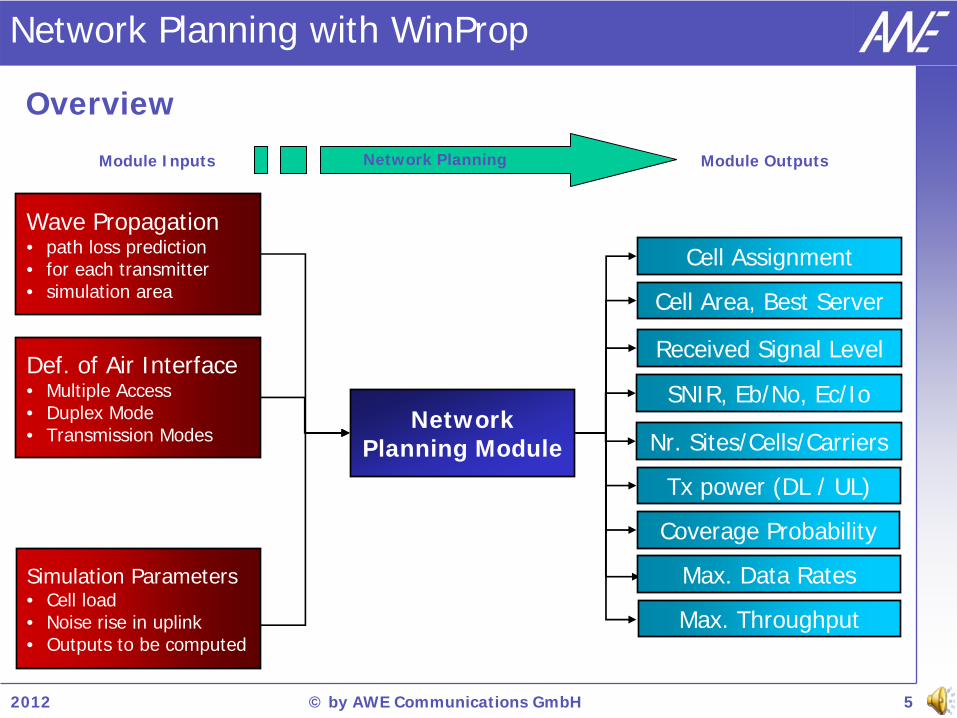
Network Planning Module
Def. of Air Interface• Multiple Access• Duplex Mode• Transmission Modes
Cell Assignment
Module Inputs Module OutputsNetwork Planning
Wave Propagation• path loss prediction• for each transmitter• simulation area Cell Area, Best Server
Received Signal Level
Nr. Sites/Cells/Carriers
Tx power (DL / UL)
Coverage Probability
Network Planning with WinProp
SNIR, Eb/No, Ec/Io
Overview
Max. Data Rates
Max. Throughput
Simulation Parameters• Cell load• Noise rise in uplink• Outputs to be computed

2012 © by AWE Communications GmbH 6
Wave Propagation (1/2)
Network Planning Module
Highly accurate wave propagation models for rural, suburban, urban indoor, and tunnel environments
Hybrid scenarios: Smooth transition between indoor, urban, and rural in one simulation
Consideration of 3D vector building databases (urban & indoor), topography (pixel), and clutter (pixel) data

2012 © by AWE Communications GmbH 7
Wave Propagation (2/2)
Angular profile
Prediction on multiple heights for indoor scenarios
Network Planning Module
Propagation paths
Propagation on multiple height levels
• Absolute / Relative to defined building floors
Propagation paths
Calculation of spatial channel impulse response, delay spread, angular spread & angular profile at Tx and Rx
Spatial channel impulse response

2012 © by AWE Communications GmbH 8
Frequency Carriers
Definition of carriers
• Bandwidth ( for noise power)
• Carrier separation
• Frequency (downlink center)
• ID of carrier
• Duplex separation (DL / UL)
• Available / not available
Carrier list in ProMan• Single / multi carrier (1st column)
• Green color indicates assigned carrier black color means not assigned
• Red color means not available carrier grey color assigned but Tx disabled
Carrier Assignment • On antenna/cell level
• Single carrier or group can be assigned
• Combination of multiple carriers to group
Network Planning Module
Carrier list in ProMan
Spectrum divided in frequency carriers

2012 © by AWE Communications GmbH 9
Transmitter Definition (1/5)
Site definition
• Name
• Location
• Type
- Site with sectors
- Leaky feeder cable
- Satellite
• Number of transmitters
Site properties• Initial properties for new sites
• Default properties
• Noise figure, cable loss,…
• Prediction area
- Individual rectangular area
- Total area (as defined on simulation page)
- Local area around transmitter (radius)
Network Planning Module

2012 © by AWE Communications GmbH 10
Transmitter Definition (2/5)
List of antennas for each site
Name of antenna
Location of antenna• x / Longitude, y / Latitude, z / Height
Enabled / disabled
RF parameters• Carrier assignment
• Tx power
• Noise figure, cable loss,…
Antenna • Azimuth, downtilt
• Antenna pattern
• ….
Network Planning Module
Properties of TRX
2012 © by AWE Communications GmbH 11
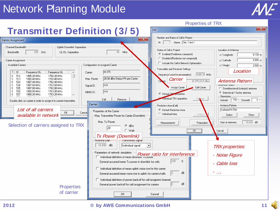
Transmitter Definition (3/5)
Network Planning Module
Selection of carriers assigned to TRX
Properties of TRX
Properties of carrier
Tx Power (Downlink)
Power ratio for interference
List of all carriers available in network
TRX properties:
- Noise Figure
- Cable loss
- ….
Antenna PatternCarrier
Location

2012 © by AWE Communications GmbH 12
Transmitter Definition (4/5)
Leaky feeder cable
Draw route with the mouse
Definition of height
RF parameters• Power at start point
• Cable loss along the leaky feeder cable [dB/100m]
• Coupling loss [dB]
• Distance for coupling loss [m]
Network Planning Module

2012 © by AWE Communications GmbH 13
Transmitter Definition (5/5)
Feeder cable for antennas
Draw route with the mouse
Modification of coordinates (height)
RF parameters• Definition of specific loss
• Computation of length
• Resulting cable loss
• Assignment to antenna via individual TRX properties
Network Planning Module
2012 © by AWE Communications GmbH 14
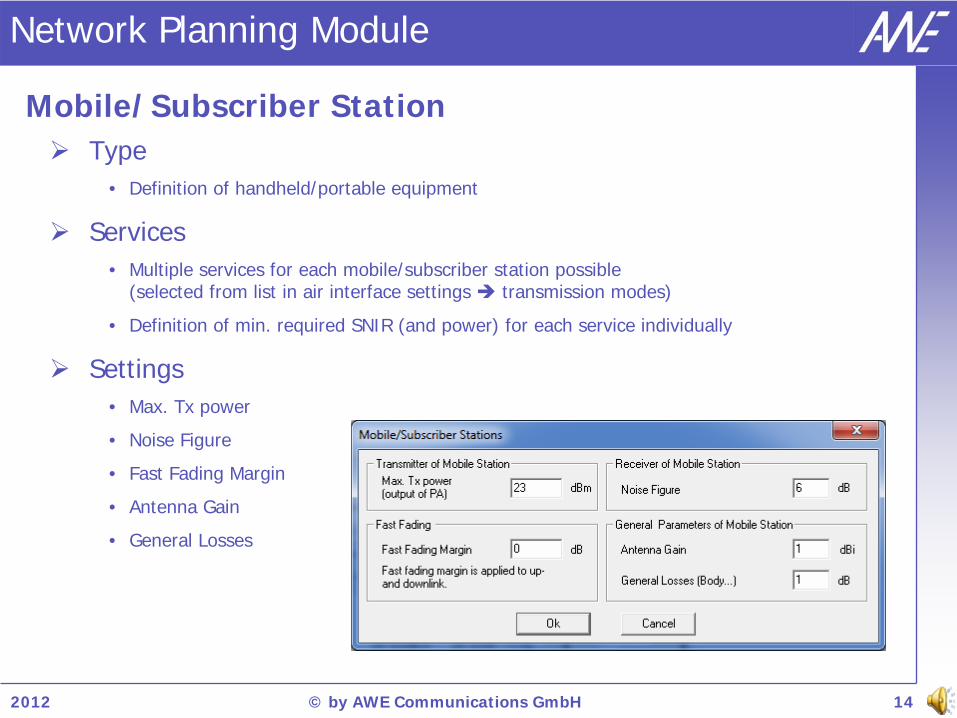
Network Planning Module
Type • Definition of handheld/portable equipment
Services• Multiple services for each mobile/subscriber station possible
(selected from list in air interface settings transmission modes)
• Definition of min. required SNIR (and power) for each service individually
Settings • Max. Tx power
• Noise Figure
• Fast Fading Margin
• Antenna Gain
• General Losses
Mobile/Subscriber Station

2012 © by AWE Communications GmbH 15
Network Planning Module
BS power definitions• Output power of the power amplifier (OPA): PC = PA - Cable Loss, PE = PC + BS Antenna Gain
• EIRP or ERP mode: PE defined directly by user (incl. cable loss and BS antenna gain)
MS power definitions • PR1 is the received power incl. the MS antenna gain
• Propagation results & settings do not include MS antenna gain (power (PR2 ), path loss, …)
• Path loss independent of the power mode (OPA, EIRP, ERP) and cable loss: PL = PE - PR2
• Network planning results: BS and MS antenna gain included: PR1 (max. received MS power)PA (min. BS transmit power)
Power Definitions for Downlink
2012 © by AWE Communications GmbH 16
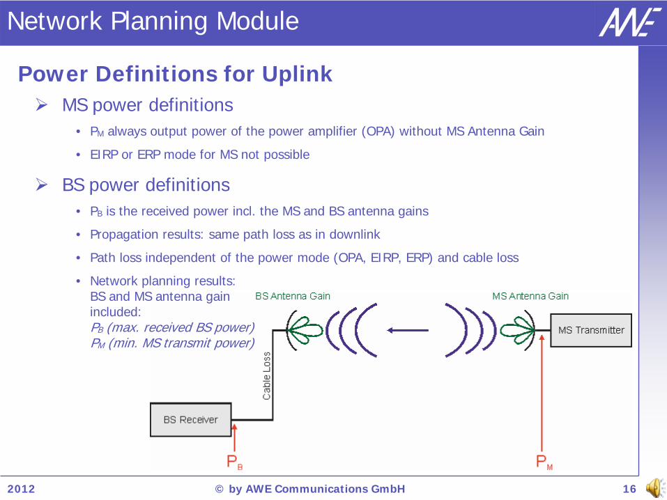
Network Planning Module
MS power definitions• PM always output power of the power amplifier (OPA) without MS Antenna Gain
• EIRP or ERP mode for MS not possible
BS power definitions • PB is the received power incl. the MS and BS antenna gains
• Propagation results: same path loss as in downlink
• Path loss independent of the power mode (OPA, EIRP, ERP) and cable loss
• Network planning results: BS and MS antenna gain included: PB (max. received BS power)PM (min. MS transmit power)
Power Definitions for Uplink
2012 © by AWE Communications GmbH 17
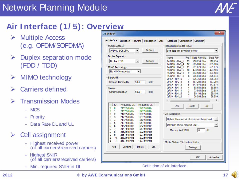
Air Interface (1/5): Overview
Multiple Access (e.g. OFDM/SOFDMA)
Duplex separation mode (FDD / TDD)
MIMO technology
Carriers defined
Transmission Modes- MCS- Priority- Data Rate DL and UL
Cell assignment- Highest received power
(of all carriers/received carriers)- Highest SNIR
(of all carriers/received carriers)- Min. required SNIR in DL Definition of air interface
Network Planning Module
2012 © by AWE Communications GmbH 18
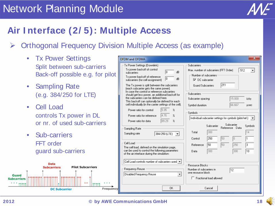
Orthogonal Frequency Division Multiple Access (as example)
• Tx Power Settings Split between sub-carriers Back-off possible e.g. for pilot
• Sampling Rate (e.g. 384/250 for LTE)
• Cell Load controls Tx power in DL or nr. of used sub-carriers
• Sub-carriers FFT order guard sub-carriers
Air Interface (2/5): Multiple Access
Network Planning Module
2012 © by AWE Communications GmbH 19
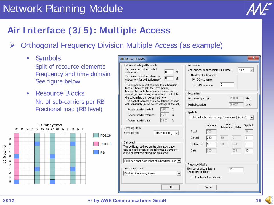
Orthogonal Frequency Division Multiple Access (as example)
• Symbols Split of resource elements Frequency and time domain See figure below
• Resource Blocks Nr. of sub-carriers per RB Fractional load (RB level)
Air Interface (3/5): Multiple Access
Network Planning Module

2012 © by AWE Communications GmbH 20
Specification of an arbitrary number of transmission modes• Name: MCS - code rate
• Priority: Impacts filling of resources (overall throughput)
• Transmission direction Bidirectional, DL only, UL only
• Modulation BPSK, QPSK, 16-QAM, 64-QAM
• Code Rate 1/3, 1/2, 3/4, 4/5,…
• Number of resource blocks
• Data rate incl. overhead
• Min. required SNIR target
• Min. required received signal level at BTS and SS• Power back-off
Air Interface (4/5): Transmission Modes
Network Planning Module

2012 © by AWE Communications GmbH 21
Duplex Mode:• TDD or FDD mode can be selected
(identical for all BTS in network)• FDD
Specification of carrier separation of UL and DL (identical for all carriers)
• TDD Definition of switching type
Definition of transmission blocks with number and length
Ratio inside each block
Resulting overall ratios for DL and UL automatically computed and considered in network simulation
Air Interface (5/5): Duplex Mode
Network Planning Module

2012 © by AWE Communications GmbH 22
Distributed Antenna and MIMO Antenna Systems (1/2)
Network Planning Module
Antenna Type Signal Group MIMO Stream
Conventional antenna Individual Not available
Antenna belonging to DAS A / B / C / … No MIMO
Antenna belonging to MIMO A / B / C / … MIMO stream 1 / stream 2
Different antenna types
Computation of Rx power Antenna Type Received Power
Conventional antenna Received power from serving cell
Antenna belonging to distributed antenna system
(DAS)
Superposition of received power values from all antennas
belonging to DAS of serving cell
Antenna belonging to MIMO system
Superposition of received power values from all antennas
transmitting the same MIMO stream as the serving cell
2012 © by AWE Communications GmbH 23
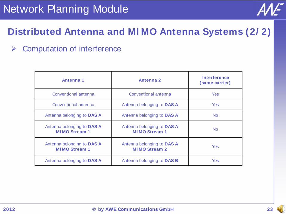
Distributed Antenna and MIMO Antenna Systems (2/2)
Network Planning Module
Computation of interference
Antenna 1 Antenna 2 Interference(same carrier)
Conventional antenna Conventional antenna Yes
Conventional antenna Antenna belonging to DAS A Yes
Antenna belonging to DAS A Antenna belonging to DAS A No
Antenna belonging to DAS AMIMO Stream 1
Antenna belonging to DAS AMIMO Stream 1 No
Antenna belonging to DAS AMIMO Stream 1
Antenna belonging to DAS AMIMO Stream 2 Yes
Antenna belonging to DAS A Antenna belonging to DAS B Yes

2012 © by AWE Communications GmbH 24
MIMO Technology (1/2)
Definition of separate antenna for each MIMO antenna element
Carrier assignment for MIMO antenna - Definition of same signal group ID - Assignment of individual MIMO stream
Network Planning Module

2012 © by AWE Communications GmbH 25
MIMO Technology (2/2)
Signaling overhead (spatial multiplex)
Beamforming improves antenna gain
Interference between MIMO streams - No interference (ideal separation) - Relative contribution to interference - Location dependent contribution
Consideration of MIMO at MS - Computation of power and data rate - Superposition of data rate at MS
Example of distributed MIMO 2x2
Visualization of results with additional output
Network Planning Module

2012 © by AWE Communications GmbH 26
Comparison DAS and MIMO Antenna Systems
Consideration at carrier assignment for antenna (signal group ID)
Configuration left: Both antennas form a DAS (Signal Group A)
Configuration right: Both are MIMO antennas (Signal Group A) and transmit individual MIMO streams (site 1 MIMO stream 1 and site 2 MIMO stream 2)
Network Planning Module

2012 © by AWE Communications GmbH 27
Cell Assignment - Serving Cell (1/2)
Highest Rx power among the carriers received First the received carriers are determined based on the given criteria for SNIR and received power (optional). From the remaining received carriers the one with highest received power is chosen.
Highest Rx power of all carriers in the network First the carrier with the highest received power is chosen. If this carrier meets the criteria for SNIR and received power (optional) it is taken as serving cell. If the criteria are not met, the pixel is referred to as not served (not computed in result map).
Highest SNIR among the carriers received First the received carriers are determined based on the given criteria for SNIR and received power (optional). From the remaining received carriers the one with the highest SNIR is chosen as serving cell.
Highest SNIR of all carriers in the network First the carrier with the highest SNIR is chosen. If this carrier meets the criteria for SNIR and received power (optional) it is taken as serving cell. If the criteria are not met, the pixel is referred to as not served (not computed in result map).
Network Planning Module

2012 © by AWE Communications GmbH 28
Cell Assignment - Serving Cell (2/2)
Example with two cells A and B and the following criteria • Min. required SNIR 3 dB • Min. required received power -90 dBm
Network Planning Module
CriterionExample 1 Example 2 Example 3 Example 4
Cell A Cell B Cell A Cell B Cell A Cell B Cell A Cell B
Received power at receiver pixel
-80.0 dBm
-85.0 dBm
-80.0 dBm
-85.0 dBm
-80.0 dBm
-92.0 dBm
-80.0 dBm
-95.0 dBm
SNIR at receiver pixel 4.0 dB 4.5 dB 2.0 dB 4.5 dB 3.2 dB 4.5 dB 2.0 dB 4.5 dB
Selection Mode Serving cell Serving cell Serving cell Serving cell
Highest Rx poweramong the carriers received
Cell A Cell B Cell A not served
Highest Rx power of all carriers in the network
Cell A not served(SNIR not met) Cell A not served
Highest SNIR among the carriers received
Cell B Cell B Cell A not served
Highest SNIR of all carriers in the network
Cell B Cell Bnot served
(rec. power not met)
not served

2012 © by AWE Communications GmbH 29
Transmission Mode Priority
Network Planning Module
Sorting of transmission modes - according to priority - DL / UL data rate - Order used for result tree
Priority affects throughput - Mode with highest priority
is analyzed first - Allocating radio resources - Filling up with lower priority modes
Max. throughput for priority according to feasible DL data rate
Otherwise radio resources are used by transmission modes with lower data rate but higher priority

2012 © by AWE Communications GmbH 30
Individual Analysis of Downlink and Uplink
Transmission modes can be defined in different ways
Bidirectional, DL only, UL only
If one direction is blocked mode not available
Individual analysis feasible
Computed results:
- DL Tx Power BS: min. required power for service (incl. power control)
- DL Rx Power MS: max. available power for service (full power transmission)
- DL SNIR: max. available SNIR for service (full power transmission)
- UL Tx Power MS: min. required power for service (incl. power control)
- UL Rx Power BS: max. available power for service (full power transmission)
- UL SNIR: max. available SNIR for service (full power transmission)
Network Planning Module

2012 © by AWE Communications GmbH 31
Definition of Cell Load (Interference)
Network Planning Module
Definition of relative transmit power if no traffic is considered
Interference (SNIR) calculation influenced by this parameter
• Value indicates how much of the data transmission power should be considered for the interference calculation
• 50% means 50% of the linear data transmission power (in Watts)
• Data transmission power is calculated based on total transmit power, the power split (data/reference/control) and the power backoff value
• Controls either Tx power or number of sub-carriers used
Cell load can be defined globally or individually for each transmitter
2012 © by AWE Communications GmbH 32
Inter-cell interference (other cells using the same carrier)
• Interference computation based on cell assignment
• Tx power of interfering BS is specified relative to max. Tx power of the BS (e.g. 80% of max. power)
- For all BTS in the network homogenously
- For each BTS individually
- Especially important if frequency reuse factor is equal to 1 (or 3)
- Sub-channelization can be modeled (if adjacent cells use different sub-carriers to reduce the interference)
• Cell load by relative Tx power of interfering cells is suitable to define typical and/or worst case scenario (sufficient for network planning)
• Actual traffic (load) of BTS depending on the number of users in the cell is not considered to determine Tx power because
- Actual Tx power depends on transmission modes
- Resource management must be included in simulator to decide which user/traffic is transmitted in which transmission mode
typically resource management is operator dependent and cannot be handled in an external planning tool
Network Simulation (Interference)
Network Planning Module

2012 © by AWE Communications GmbH 33
Network projects with multiple assigned (frequency) carriers
• Results provided for each carrier individually
- Based on individual cell assignment
- Assuming only the investigated carrier is currently available
• Superposed results considering all carriers in the network
- Based on final cell assignment considering all carriers
- Results for serving cell are given
- Data rate and throughput results are not superposed
Simulation of each carrier individually
Network Planning Module

2012 © by AWE Communications GmbH 34
Simulation Results (depending on air interface)
General results
• Best server, cell/site areas
• Max received power (DL/UL)
• Max data rate (DL/UL)
Cell assignment (control) • Received power level
• SNIR or Eb/No
• Received sites, cells, carriers
Transmission mode results• Max Rx power MS (full power BS)
• Min Tx power BS
• Max SNIR (full power BS)
• Max data rate per user
• Number of streams
• Max throughput
Network Planning Module
For each transmission
mode
Cell Assignment
General results
Pilot resultsLTE specific
results

2012 © by AWE Communications GmbH 35
Cell Areas
Knowledge of best server especially important for cellular networks
Useful to avoid cell overloads
Computed based on defined cell assignment mode
Evaluating pilot/control channel
Cell areas for LTE network
Network Planning Module – Predicted Results

2012 © by AWE Communications GmbH 36
Network Planning Module – Predicted Results
Best Server Map and Site Areas in Building
Best server map indicates which carrier is received best
Site area map shows the dominating site over the simulation area

2012 © by AWE Communications GmbH 37
Max. Received Signal Level
Reception level on different (and multiple) heights
Reception level on street level and in different building floors
1.5m above ground 5.0m above ground 13.0m above ground
Network Planning Module – Predicted Results

2012 © by AWE Communications GmbH 38
Network Planning Module – Predicted Results
Rx Power, SNIR and Max. Throughput in Building
Prediction of received signal level
Prediction of SNIR
Computation of overall throughput

2012 © by AWE Communications GmbH 39
Signal/Noise & Interference Ratio (SNIR)
Essential for selection of feasible MCS data rate / throughput
Computed for each transmission mode individually
Prediction height: 25m above ground
Prediction height: 1.5m above ground
Network Planning Module – Predicted Results
2012 © by AWE Communications GmbH 40
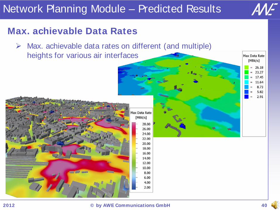
Max. achievable Data Rates
Max. achievable data rates on different (and multiple) heights for various air interfaces
Network Planning Module – Predicted Results

2012 © by AWE Communications GmbH 41
Required Tx Power for BS and MS (i.e. DL & UL)
Required Tx power for a connection between MS and BS for each transmission mode (MCS)
Actual Tx power can be higher depending on traffic load (and interference situation)
Network Planning Module – Predicted Results
Prediction height: 25m above ground
Prediction height: 1.5m above ground

2012 © by AWE Communications GmbH 42
Reception Probability (Coverage)
Consideration of the fast fading of the radio channel
Individually computed for each transmission mode
Prediction height: 25m above ground Prediction height: 1.5m above ground
Network Planning Module – Predicted Results

2012 © by AWE Communications GmbH 43
Handover options
Results show the number of received sites, antennas, carriers
For the determination of alternative sites, cells, carriers
Visualization of handover options
Multi layer prediction for office building
Network Planning Module – Predicted Results

2012 © by AWE Communications GmbH 44
Results on Prediction Planes
Visualization in 3D view
Statistical evaluation by using the info button
Network planning result in stadium
Network Planning Module – Predicted Results

2012 © by AWE Communications GmbH 47
Further Information
Further information: www.awe-com.com


