NW000-S0007 UNCONTROLLED IF PRINTED Page 1 of 35 Network Standard NETWORK Document No Amendment No Approved By Approval Date Review Date : : : : : NW000-S0007 1 Manager NR & P 28/03/2017 19/03/2020 (Full review with minor updates completed 28.03.2017) NW000-S0007 NS187 PASSIVE FIRE MITIGATION DESIGN OF SUBSTATIONS
Transcript
NW000-S0007 UNCONTROLLED IF PRINTED Page 1 of 35
Network Standard
NETWORK
Document No Amendment No Approved By Approval Date Review Date
:::::
NW000-S0007 1 Manager NR & P 28/03/2017 19/03/2020
(Full review with minor updates completed 28.03.2017)
NW000-S0007 NS187 PASSIVE FIRE MITIGATION DESIGN OF SUBSTATIONS
NS187 Passive Fire Mitigation Design of Substations Amendment No 1
NW000-S0007 UNCONTROLLED IF PRINTED Page 2 of 35
ISSUE
For issue to all Ausgrid and Accredited Service Providers’ staff involved with the design of substations.
Ausgrid maintains a copy of this and other Network Standards together with updates and amendments on www.ausgrid.com.au.
Where this standard is issued as a controlled document replacing an earlier edition, remove and destroy the superseded document
DISCLAIMER
As Ausgrid’s standards are subject to ongoing review, the information contained in this document may be amended by Ausgrid at any time.
It is possible that conflict may exist between standard documents. In this event, the most recent standard shall prevail.
This document has been developed using information available from field and other sources and is suitable for most situations encountered in Ausgrid. Particular conditions, projects or localities may require special or different practices. It is the responsibility of the local manager, supervisor, assured quality contractor and the individuals involved to make sure that a safe system of work is employed and that statutory requirements are met.
Ausgrid disclaims any and all liability to any person or persons for any procedure, process or any other thing done or not done, as a result of this Standard.
All design work, and the associated supply of materials and equipment, must be undertaken in accordance with and consideration of relevant legislative and regulatory requirements, latest revision of Ausgrid’s Network Standards and specifications and Australian Standards. Designs submitted shall be declared as fit for purpose. Where the designer wishes to include a variation to a network standard or an alternative material or equipment to that currently approved the designer must obtain authorisation from the Network Standard owner before incorporating a variation to a Network Standard in a design.
External designers including those authorised as Accredited Service Providers will seek approval through the approved process as outlined in NS181 Approval of Materials and Equipment and Network Standard Variations. Seeking approval will ensure Network Standards are appropriately updated and that a consistent interpretation of the legislative framework is employed.
Note that compliance with this Network Standard does not automatically satisfy the requirements of a Designer Safety Report. The designer must comply with the provisions of the Workplace Health and Safety Regulation 2011 (NSW - Part 6.2 Duties of designer of structure and person who commissions construction work) which requires the designer to provide a written safety report to the person who commissioned the design. This report must be provided to Ausgrid in all instances, including where the design was commissioned by or on behalf of a person who proposes to connect premises to Ausgrid’s network, and will form part of the Designer Safety Report which must also be presented to Ausgrid. Further information is provided in Network Standard (NS) 212 Integrated Support Requirements for Ausgrid Network Assets.
INTERPRETATION
In the event that any user of this Standard considers that any of its provisions is uncertain, ambiguous or otherwise in need of interpretation, the user should request Ausgrid to clarify the provision. Ausgrid’s interpretation shall then apply as though it was included in the Standard, and is final and binding. No correspondence will be entered into with any person disputing the meaning of the provision published in the Standard or the accuracy of Ausgrid’s interpretation.
KEYPOINTS
This standard has a summary of content labelled “KEYPOINTS FOR THIS STANDARD”. The inclusion or omission of items in this summary does not signify any specific importance or criticality to the items described. It is meant to simply provide the reader with a quick assessment of some of the major issues addressed by the standard. To fully appreciate the content and the requirements of the standard it must be read in its entirety.
AMENDMENTS TO THIS STANDARD
Where there are changes to this standard from the previously approved version, any previous shading is removed and the newly affected paragraphs are shaded with a grey background. Where the document changes exceed 25% of the document content, any grey background in the document is to be removed and the following words should be shown below the title block on the right hand side of the page in bold and italic, for example, Supersedes – document details (for example, “Supersedes Document Type (Category) Document No. Amendment No.”).
KEY POINTS OF THIS STANDARD
NW000-S0007 UNCONTROLLED IF PRINTED Page 3 of 35
Passive Fire Protection Egress Provisions and Public Safety
Bushfire Protection Scope and Risks Addressed
Tools and Forms Annexure D – Sample Compliance Checklist
Tools and Forms Annexure D –Sample Compliance Checklist
This standard is limited to scope identified below and provides controls for associated risks as listed below:
This standard details minimum levels of passive fire protection systems for the protection of Ausgrid’s substations
Design of emergency egress capabilities within substations is an important focus of the standard
The standard applies only to sub-transmission, and zone substations. Chamber substations are covered by NS 113.
The design concepts are intended to be applied to new substation designs although they can be applied to existing substations as directed by Ausgrid Primary Systems
This standard does not apply for kiosks substations or pole top equipment, e.g. transformers, capacitors and reclosers.
Protection of buildings against fire shall be to minimum requirements of the Building Code of Australia.
This standard addresses only passive controls – refer to NEGSM07 Active Fire Systems for Substations for details on active control systems.
Passive control systems are required to be the primary fire protection system
Examples of passive systems include fire separation walls, fire barriers, fire stopping, fire dampers, minimum separation distances, bunding, etc.
Where to for more information? Section 1, 2, and 6
Fire mitigation design shall consider the substation criticality, fuel loading, response time, and public/personnel safety. Key design criteria include:
the fire intensity, fire duration and oil containment capabilities.
fire separation wall requirements vertical and horizontal separation
distances between buildings and equipment
compartmentalisation radiant heat exposure limits for
different construction materials and equipment
protection requirements for different equipment types
proximity and construction materials used in adjacent properties
location of doors ,windows and vents use of fire stopping to seal cables and
other openings in walls, floors and ceilings
cable fire retardant coatings (see NS171 for more detail)
substation overpressure (see more detail in NS188)
Egress provisions include consideration of access to escape safely as well as providing access for switching and control of equipment. Provisions include:
Minimum of two paths of emergency egress from a compartment with HV equipment, except where an exemption is allowed
Consideration of radiant heat levels and exposure times
Effect of wind on fire plumes Minimum standard for Public Safety is Building Code of Australia. Consideration is also given to:
Adjacent and adjoining properties Heat flux limits Building materials used in adjacent,
adjoining properties.
This section provides guidance for protecting the substation against bush fires. It does not cover the requirements for protecting the bush against fire from equipment failure. Key points in protection during bushfire events include:
Availability to maintain supply during and after the bushfire to support the needs of the local community
Overall approach taken will be site dependent and based on substation criticality
Annexure A provides required fire resistance levels for different equipment types.
Adequate set-backs from property boundaries or suitable fire barriers are considered the main defence against radiant heat damage from bushfires
Tools and Forms Annexure D – Sample Compliance Checklist
Where to for more information? Section 7, 8, 10
Where to for more information? Section 9, 11
Where to for more information? Section 12
NS187 Passive Fire Mitigation Design of Substations Amendment No 1
6.0 THE APPROACH ................................................................................................................................. 12 6.1 General .................................................................................................................................... 12 6.2 Fire risk zones .......................................................................................................................... 12 6.3 Passive fire protection .............................................................................................................. 12 6.4 Active fire protection................................................................................................................. 12
6.4.1 General ......................................................................................................................... 12 6.4.2 Limitations of active systems ....................................................................................... 13 6.4.3 Application of active systems ....................................................................................... 13
6.5 Typical properties of combustible liquids ................................................................................. 13
7.0 PASSIVE FIRE MITIGATION DESIGN ............................................................................................... 14 7.1 General .................................................................................................................................... 14 7.2 Key design criteria .................................................................................................................... 14
7.2.1 Oil fires ......................................................................................................................... 14 7.2.2 Fire separation walls .................................................................................................... 14 7.2.3 Special design requirements ........................................................................................ 15
8.0 PASSIVE FIRE PROTECTION SYSTEMS ......................................................................................... 16 8.1 General .................................................................................................................................... 16 8.2 Passive fire protection within buildings .................................................................................... 16
8.3 Passive fire protection external to buildings ............................................................................ 16 8.3.1 General ......................................................................................................................... 16 8.3.2 Separation distances for buildings and transformers ................................................... 17 8.3.3 Fire separation walls for transformers .......................................................................... 18 8.3.4 Separation distances for other switchyard equipment ................................................. 19
9.0 EGRESS PROVISIONS....................................................................................................................... 20 9.1 Emergency egress within buildings .......................................................................................... 20 9.2 Emergency egress external to buildings .................................................................................. 20
NS187 Passive Fire Mitigation Design of Substations Amendment No 1
NW000-S0007 UNCONTROLLED IF PRINTED Page 5 of 35
10.0 SPECIAL DETAILED DESIGN REQUIREMENTS .............................................................................. 21 10.1 Scope ....................................................................................................................................... 21 10.2 Openings in fire barrier walls and fire separation walls ........................................................... 21
10.2.1 General ......................................................................................................................... 21 10.2.2 Doors ............................................................................................................................ 21 10.2.3 Vent openings .............................................................................................................. 21 10.2.4 Minimum clearance to fire doors and fire dampers ...................................................... 21
10.3 Switchyard trenches and other locations ................................................................................. 22 10.4 Firestopping ............................................................................................................................. 22 10.5 Smoke seals ............................................................................................................................. 22 10.6 Roof system ............................................................................................................................. 22
10.6.1 General ......................................................................................................................... 22 10.6.2 Internal fire protection .................................................................................................. 22 10.6.3 External fire protection ................................................................................................. 22
ANNEXURE A – PASSIVE FIRE MITIGATION REQUIREMENTS ................................................................ 28
ANNEXURE B – TYPICAL PROPERTIES OF COMBUSTIBLE LIQUIDS ..................................................... 30
ANNEXURE C – BACKGROUND INFORMATION RELATING TO PASSIVE FIRE PROTECTION ............. 31 C.1 General .................................................................................................................................... 31 C.2 Cable marshalling areas .......................................................................................................... 31 C.3 Oil containment bund drainage ................................................................................................ 31 C.4 Transformer bushings .............................................................................................................. 32 C.5 Transformer tank ...................................................................................................................... 32 C.6 Response to major fires ........................................................................................................... 32
ANNEXURE D – SAMPLE COMPLIANCE CHECKLIST ................................................................................ 34
NS187 Passive Fire Mitigation Design of Substations Amendment No 1
NW000-S0007 UNCONTROLLED IF PRINTED Page 6 of 35
1.0 PURPOSE
This Network Standard details Ausgrid’s minimum levels of passive fire protection systems needed to provide a cost and performance effective solution for the protection of Ausgrid’s substations.
The requirements in this Network Standard in some instances are over and above the minimum requirements of relevant statutory regulations given the unique risks of substations. The primary aim is to provide a greater level of awareness and direction regarding passive fire protection of substations and surrounding properties, as well as the minimum requirements for personnel safety and emergency egress in the event of fire.
The requirements in this Network Standard have been developed by assessing the unique risks and past experiences relating to fuel loading, reduced reliability of active systems, isolation and de-energising times and fire-fighting response times.
2.0 SCOPE
The objective of this Network Standard is to provide details of the design of passive fire mitigation requirements for substations and for safe egress from substation buildings and switchyards in the event of a fire.
This Standard covers sub-transmission and zone substations. Chamber substations are covered by NS 113, and some details have been included in this Standard for completeness and reference purposes only.
This Standard does not include provisions for kiosk substations (refer to NS 141) or pole top equipment such as transformers, capacitors and reclosers.
Where this Network Standard is to be applied to proposed works within an existing substation, Ausgrid Primary Systems will provide additional recommendations on the type and extent of passive fire protection to be applied.
NS187 Passive Fire Mitigation Design of Substations Amendment No 1
NW000-S0007 UNCONTROLLED IF PRINTED Page 7 of 35
3.0 REFERENCES
3.1 General All work covered in this document shall conform to all relevant Legislation, Standards, Codes of Practice and Network Standards. Current Network Standards are available on Ausgrid’s Internet site at www.ausgrid.com.au.
3.2 Ausgrid documents Bushfire Risk Management Plan Company Form (Governance) - Network Technical Document Endorsement and Approval Company Procedure (Governance) - Network Technical Document Endorsement and
Approval Company Procedure (Network) – Network Standards Compliance Company Procedure (Network) - Production / Review of Engineering Technical Documents
within BMS Division Workplace Instruction (Network) – Production /review of Network Standards Electrical Safety Rules Electricity Network Safety Management System Manual NEGSM07 Active Fire Systems for Substations. NS171 Firestopping in Substations. NS181 Approval of Materials and Equipment and Network Standard Variations NS185 Major Substations Building Design Standard. NS188 Design for Substation Overpressure NS189 Oil Containment for Major Substations NS190 Oil Containment Operational Requirements for Major Substations NS212 Integrated Support Requirements for Ausgrid Network Assets NS261 Requirement for Design Compliance Framework for Network Standards
3.3 Other standards and documents AS/NZS 1170.0 Structural design actions - General principles. AS 1530.1 Methods for fire tests on building materials, components and structures –
Combustibility test for materials. AS 1530.4 Methods for fire tests on building materials, components and structures Fire-
resistance tests of elements of building construction. AS 1530.8.1 Methods for fire tests on building materials, components and structures - Tests
on elements of construction for buildings exposed to simulated bushfire attack - Radiant heat and small flaming sources.
AS 1530.8.2 Methods for fire tests on building materials, components and structures - Tests on elements of construction for buildings exposed to simulated bushfire attack - Large flaming sources.
AS 2067Substations and high voltage installations exceeding 1kV a.c. AS 2484.1 Fire - Glossary of terms – Fire tests. AS 3600 Concrete structures. AS 3700 Masonry structures. AS 3959 Construction of buildings in bushfire-prone areas. AS 4072.1 Components for the protection of openings in fire resistant separating Elements –
Service penetrations and control points. AS 4100 Steel structures. ENA Doc 001 National Electricity Network Safety Code IEC 61039 Ed. 2.0 Classification of insulating liquids. NSW Rural Fire Services Guide, Planning for Bushfire Protection
3.4 Acts and regulations Building Code of Australia (BCA). Electricity Supply (General) Regulation 2014 (NSW) Electricity Supply (Safety and Network Management) Regulation 2014 Work Health and Safety Act 2011 and Regulation 2011
NS187 Passive Fire Mitigation Design of Substations Amendment No 1
NW000-S0007 UNCONTROLLED IF PRINTED Page 8 of 35
4.0 DEFINITIONS
Accredited Service Provider (ASP)
An individual or entity accredited by the NSW Department of Industry, Division of Resources and Energy, in accordance with the Electricity Supply (Safety and Network Management) Regulation 2014 (NSW).
Active Describes a system that has moving parts or relies on mechanical, chemical or electrical controls in order to function. Examples of active systems include fire protection systems such as sprinklers and smoke detection systems.
Approval Written consent from Ausgrid. This can be for proposals to meet the requirements of this Network Standard or for authorising specific departures from the Network Standard or where a proposal is provided which is related to this Network Standard although not sufficiently covered.
Bushfire Front For the purpose of this document, bushfire front shall be taken at a location between the substation fence and the boundary depending on land use within the boundary.
Business Management System (BMS)
An Ausgrid internal integrated policy and procedure framework that contains the approved version of documents.
Cable A single conductor (with its insulation but not including any mechanical protective covering), or two or more conductor cores laid together, either with or without fillings, reinforcements, or protective coverings.
Cable Marshalling Areas
Areas where groups of cables are present such as cable basements, jointing areas, galleries and pits all within substations.
Combustible Liquid
Any liquid other than a flammable liquid that has a flash point and a fire point less than its boiling point. Combustible liquids can be divided into two categories: Class C1 and Class C2. The flash point of these combustible liquids is less than or equal to 150oC and exceeds 150oC respectively.
Compartmentalisation
The division of a building into discrete compartments thereby confining any potential fire to the compartment of origin with the aim to prevent the spread of the fire into adjacent compartments for a designated fire resistance period.
Convection The transfer of heat by the circulation or buoyant motions of air flow. This mode of heat transfer becomes less significant for larger lateral distances from a fire or other heat source.
Dedicated Compartment
A compartment that only has the nominated equipment contained within and only the cabling required for its operation. There is no other equipment and associated cables in the compartment.
Design Report A report prepared by an appropriately qualified engineer practicing in the specific discipline of fire engineering. The report shall provide details of the schematic designs developed and demonstrate by calculation how the objectives of passive fire mitigation performance requirements stipulated in this Network Standard are satisfied.
Document control
Ausgrid employees who work with printed copies of document must check the BMS regularly to monitor version control. Documents are considered “UNCONTROLLED IF PRINTED”, as indicated in the footer.
EGOWS Enhanced Gravity Oil Water Separator.
NS187 Passive Fire Mitigation Design of Substations Amendment No 1
NW000-S0007 UNCONTROLLED IF PRINTED Page 9 of 35
Emissivity The ratio of thermal radiation that can be emitted by a body to the amount emitted by an ideal mass or “blackbody” at the same temperature. An ideal “blackbody” is a body or mass that absorbs and re-emits all radiation incident on it. An ideal “blackbody” has an emissivity of 1.
Fire Barrier A wall, floor, ceiling bounding a fire rated compartment.
Fire Hazard A hazard that occurs when a fire risk zone extends to include other buildings, parts of the same building that house the high voltage installation, fire escape routes, or other fire sensitive locations and facilities.
Fire Intensity The rate of release of calorific energy from a fire.
Fire Rated An item or a compartment that has a Fire Resistance Level (FRL).
Fire Refuge Area A refuge area is a safe place providing refuge to personnel from a substation fire. It can be a temporary “haven” to protect people while evacuating during a fire. Refuge areas can be either inside or outside a building and must provide personnel with protection from a fire until safe escape is possible to open space.
Fire Resistance The ability of an element of construction, component or structure to maintain its structural adequacy, integrity and thermal insulation during exposure to a fire.
Fire Resistance Level (FRL)
The ability of an element of construction, component or structure to maintain its structural adequacy, integrity and thermal insulation during exposure to a fire for a specific fire resistance period. The intensity of the fire shall be equal to either the Hydrocarbon Fire (for oil fires) or the Standard Fire (for all other fires) as specified in AS 1530.4 Fire resistance tests of elements of building construction.
Fire Resistance Period (FRP)
The ability of an element of construction, component or structure to maintain a specific expected duty during exposure to a fire for a specified period of time. Fire Resistance Period is generally specified in minutes.
Fire Risk Zone A zone that extends in every direction from the perimeter of a high voltage installation. It is based on a risk assessment that considers, as a minimum, the provisions of AS 2067 – Substations and high voltage installations exceeding 1kV a.c together with the additional requirements of this Network Standard.
Fire Separation Wall (FSW)
A wall with an appropriate level of resistance to the spread of fire that divides a building (or a storey within a building) or switchyard into segregated zones.
Fire Source Any electrical apparatus (generally of high voltage) that comprises of mineral oil, or a similar combustible fluid as an insulating medium. This includes oil filled transformers and oil filled switchgear. Other fuel sources can be combustible construction materials, cables etc.
Fire Source Feature
Fire-source feature in accordance with the Building Code of Australia (BCA) is defined as:
the far boundary of a road adjoining the allotment; or a side or rear boundary of the allotment; or an external wall of another building on the allotment which is not a Class 10
building (a non-habitable building or structure, eg carport, shed, fence, free standing wall etc.).
Note: For the purpose of this Network Standard, there is a clear distinction between a Fire source feature (BCA) and the Fire source.
Flash Point The temperature at which a liquid first evolves vapour in a sufficient quantity to be ignited by a specified flame but not necessarily propagate.
NS187 Passive Fire Mitigation Design of Substations Amendment No 1
NW000-S0007 UNCONTROLLED IF PRINTED Page 10 of 35
Heat Flux Incident heat power per unit area. This includes both radiant heat flux and convective heat flux.
Ignition Source A source of energy sufficient to ignite a flammable atmosphere.
Linear Compartmentalisation
Segregation of individual power transition, switching and control such that if loss of one system is disrupted in the event of a fire, the other system(s) configurations remain functional.
Network Standard
A document, including Network Planning Standards, that describes the Company's minimum requirements for planning, design, construction, maintenance, technical specification, environmental, property and metering activities on the distribution and transmission network. These documents are stored in the Network Category of the BMS repository.
Non combustible A material not deemed combustible under AS 1530.1 Methods for fire tests on building materials, components and structures – Combustibility test for materials, or a building element or section that comprises wholly of materials that are not deemed to be combustible.
Non piloted ignition
Externally induced ignition where the onset of the flaming combustion process is initiated, without the presence of a pilot, by energy from an external source.
Passive Describes a system that relates to fire protection that has no moving parts or does not rely on other external controls in order to function as intended. Examples of passive systems include fire rated building elements such as fire barrier walls and fire doors in the closed position etc.
Piloted ignition Externally induced ignition where the onset of combustion is initiated by near contact of a flame or an arc source (the pilot) with a gas or with volatiles from a liquid or from a body undergoing thermal degradation.
Note: Ignition will not occur without oxygen.
PPS Parallel Plate Coalescing Separator also known as a PPS. PPSs are gravity separation separators.
Primary Systems A section in the Ausgrid organisational structure under Network Risk Management & Planning.
Project Development
A section under Ausgrid’s organisational structure under Major Project Services.
Radiation The transfer of heat energy between two or more masses or bodies through radiation. The net effect is that heat is transferred from the hotter body to the cooler body. No medium needs to exist between the two bodies for this type of heat transfer to occur. In the context of this Network Standard, radiant heat is the transfer of heat from a fire engulfed elements to the surrounding objects.
Review date The review date displayed in the header of the document is the future date for review of a document. The default period is three years from the date of approval however a review may be mandated at any time where a need is identified. Potential needs for a review include changes in legislation, organisational changes, restructures, occurrence of an incident or changes in technology or work practice and/or identification of efficiency improvements.
Segregated zones
Areas or equipment that are segregated from other areas or equipment by either spatial separation sufficient to prevent ignition or by fire barrier walls or fire separation walls. Segregated zones also includes the prevention of fire tracking along cables and the prevention of burning oil spreading from one zone to another. Segregated zones may also be required to prevent damage by heat in specific applications. Segregated zones are not
NS187 Passive Fire Mitigation Design of Substations Amendment No 1
NW000-S0007 UNCONTROLLED IF PRINTED Page 11 of 35
overlapped.
Substation Substations in this document include sub-transmission and zone substations with the voltages of 132, 66, 33 & 11 kV. It also includes ground-mounted regulators and ground mounted tap changer auto-transformer substations.
Switchgear Equipment for controlling the distribution of electrical energy or for controlling or protecting circuits, machines, transformers, or other equipment.
Temporary Relates to the substation type and has a design life of 20 years. Refer to NS185 Major Substations Building Design Standard for a further explanation of the various types of substations.
Transformer A static item of apparatus with one or more windings which, by electromagnetic induction, transforms a system of alternating voltage and current into another system of voltage and current usually of different values but with the same frequency, for the purpose of transmitting electrical power.
Uncontrolled Arc An electric arc under abnormal conditions that is neither deliberate nor contained and is exposed to fuel and/or air.
5.0 ASBESTOS
All materials and equipment used for construction of Ausgrid’s assets are to be free from Asbestos and or Asbestos related products. Suppliers are expected to comply with the Work Health and Safety Act 2011 (NSW) together with the Work Health and Safety Regulation 2011 (NSW) and confirm in writing that all products supplied to Ausgrid contain no Asbestos related materials.
NS187 Passive Fire Mitigation Design of Substations Amendment No 1
NW000-S0007 UNCONTROLLED IF PRINTED Page 12 of 35
6.0 THE APPROACH
6.1 General Fire protection shall be provided where a potential fire hazard exists due to a fire initiated or propagated by any part or element of a high voltage installation.
The minimum requirements that shall apply for the protection of buildings against fire are those contained in the Building Code of Australia (BCA).
Fire protection can be broken down into two specific areas: Passive fire protection systems and Active fire protection systems.
The intention of this document is to provide design guidance on passive fire systems generally as the first line of defence and preferred means of fire spread prevention in substations.
Refer to NEGSM07 Active Fire Systems for Substations for details on active fire systems.
6.2 Fire risk zones Fire risk zones for high voltage installations such as substations shall be based on a risk assessment that considers, as a minimum, the provisions of AS 2067 Substations and high voltage installations exceeding 1kV a.c. together with the additional requirements of this Network Standard.
If any part of the fire risk zone extends to include other buildings, parts of the same building that house the high voltage installation, fire escape routes, or other fire sensitive locations and facilities, then a potential fire hazard exists.
Where a fire hazard exists, high voltage installation enclosures within or adjacent to buildings shall be designed with suitable fire protection to meet the requirements of AS 2067 and this Network Standard.
6.3 Passive fire protection Passive fire systems are required to minimise the risk of damage from the spread of fire from one segregation zone to another.
Except where exceptional circumstances apply, active fire protection systems shall be used only as additional protection to passive systems and not as a substitute to passive fire protection systems. Refer to Clause 6.4 for the general requirements of active fire protection systems in relation to passive fire systems. NEGSM07 covers the details on active fire protection systems.
Examples of passive fire protection systems include:
Fire separation walls and fire barriers. Fire stopping and fire dampers to penetrations within fire barriers. Self-closing fire doors to openings in fire separation walls and fire barriers. Minimum fire separation distances from fire sources. Oil containment/bunding.
6.4 Active fire protection
6.4.1 General The general requirements of active fire protection systems in relation to passive fire systems are covered below. NEGSM07 has the complete details on active fire protection systems.
Active fire extinguishing systems such as sprinklers and deluge systems aim at reducing the damage due to burning equipment by reducing or eliminating any fire or smoke damage to the remaining substation and equipment. Active systems assist in reducing the overall damage:
by providing early warning for Ausgrid and/or Fire Brigade intervention.
by reducing the duration of a fire and providing a safe means of extinguishing the fire without isolating and earthing.
NS187 Passive Fire Mitigation Design of Substations Amendment No 1
NW000-S0007 UNCONTROLLED IF PRINTED Page 13 of 35
by overcoming access problems for fire fighting.
by limiting the spread of fire within a compartment.
by reducing smoke.
by providing, in some cases, cooling to adjoining areas.
by providing a secondary system in the event the primary passive system is compromised prior or during a fire event.
where linear compartmentalisation may be a consideration, such as some CBD cable basements, but is not possible. Note that alternative passive fire protection systems may be available at these locations e.g. cable fire protection or flame retardant cable insulation.
6.4.2 Limitations of active systems The Designer shall make allowances for all the credible limitations of active systems including any WHS and environmental impacts.
6.4.3 Application of active systems The following active fire systems shall be installed throughout Ausgrid substation buildings unless otherwise specified:
Smoke Detection System (except for distribution substations) Fire Extinguishers
These active fire systems shall comply with the design requirements of Ausgrid.
Consideration shall only be given to the use of other active fire systems when required by the BCA. The use of an active fire system to supplement a passive system must have written approval from Ausgrid.
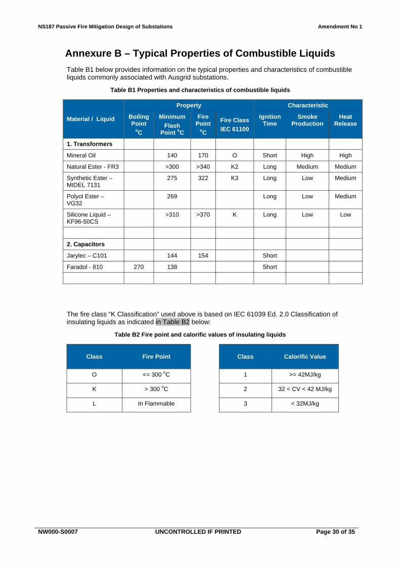
6.5 Typical properties of combustible liquids Annexure B provides information on the typical properties and characteristics of combustible liquids commonly associated with Ausgrid substations.
NS187 Passive Fire Mitigation Design of Substations Amendment No 1
NW000-S0007 UNCONTROLLED IF PRINTED Page 14 of 35
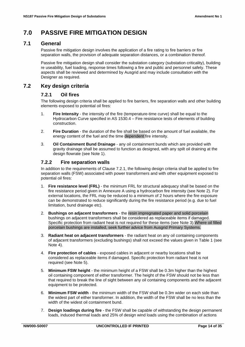
7.0 PASSIVE FIRE MITIGATION DESIGN
7.1 General Passive fire mitigation design involves the application of a fire rating to fire barriers or fire separation walls, the provision of adequate separation distances, or a combination thereof.
Passive fire mitigation design shall consider the substation category (substation criticality), building re useability, fuel loading, response times following a fire and public and personnel safety. These aspects shall be reviewed and determined by Ausgrid and may include consultation with the Designer as required.
7.2 Key design criteria
7.2.1 Oil fires The following design criteria shall be applied to fire barriers, fire separation walls and other building elements exposed to potential oil fires:
1. Fire Intensity - the intensity of the fire (temperature-time curve) shall be equal to the Hydrocarbon Curve specified in AS 1530.4 – Fire resistance tests of elements of building construction.
2. Fire Duration - the duration of the fire shall be based on the amount of fuel available, the energy content of the fuel and the time dependent fire intensity.
3. Oil Containment Bund Drainage - any oil containment bunds which are provided with gravity drainage shall be assumed to function as designed, with any spilt oil draining at the design flowrate (see Note 1).
7.2.2 Fire separation walls In addition to the requirements of Clause 7.2.1, the following design criteria shall be applied to fire separation walls (FSW) associated with power transformers and with other equipment exposed to potential oil fires:
1. Fire resistance level (FRL) - the minimum FRL for structural adequacy shall be based on the fire resistance period given in Annexure A using a hydrocarbon fire intensity (see Note 2). For external locations, the FRL may be reduced to a minimum of 2 hours where the fire exposure can be demonstrated to reduce significantly during the fire resistance period (e.g. due to fuel limitation, bund drainage etc).
2. Bushings on adjacent transformers - the resin impregnated paper and solid porcelain bushings on adjacent transformers shall be considered as replaceable items if damaged. Specific protection from radiant heat is not required for these items (see Note 3).Where oil filled porcelain bushings are installed, seek further advice from Ausgrid Primary Systems.
3. Radiant heat on adjacent transformers - the radiant heat on any oil containing components of adjacent transformers (excluding bushings) shall not exceed the values given in Table 1 (see Note 4).
4. Fire protection of cables - exposed cables in adjacent or nearby locations shall be considered as replaceable items if damaged. Specific protection from radiant heat is not required (see Note 5).
5. Minimum FSW height - the minimum height of a FSW shall be 0.3m higher than the highest oil containing component of either transformer. The height of the FSW should not be less than that required to break the line of sight between any oil containing components and the adjacent equipment to be protected.
6. Minimum FSW width - the minimum width of the FSW shall be 0.3m wider on each side than the widest part of either transformer. In addition, the width of the FSW shall be no less than the width of the widest oil containment bund.
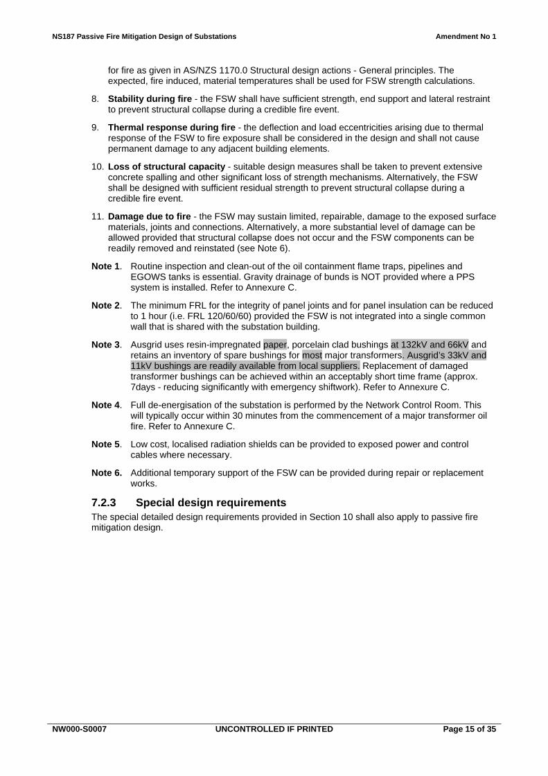
7. Design loadings during fire - the FSW shall be capable of withstanding the design permanent loads, induced thermal loads and 25% of design wind loads using the combination of actions
NS187 Passive Fire Mitigation Design of Substations Amendment No 1
NW000-S0007 UNCONTROLLED IF PRINTED Page 15 of 35
for fire as given in AS/NZS 1170.0 Structural design actions - General principles. The expected, fire induced, material temperatures shall be used for FSW strength calculations.
8. Stability during fire - the FSW shall have sufficient strength, end support and lateral restraint to prevent structural collapse during a credible fire event.
9. Thermal response during fire - the deflection and load eccentricities arising due to thermal response of the FSW to fire exposure shall be considered in the design and shall not cause permanent damage to any adjacent building elements.
10. Loss of structural capacity - suitable design measures shall be taken to prevent extensive concrete spalling and other significant loss of strength mechanisms. Alternatively, the FSW shall be designed with sufficient residual strength to prevent structural collapse during a credible fire event.
11. Damage due to fire - the FSW may sustain limited, repairable, damage to the exposed surface materials, joints and connections. Alternatively, a more substantial level of damage can be allowed provided that structural collapse does not occur and the FSW components can be readily removed and reinstated (see Note 6).
Note 1. Routine inspection and clean-out of the oil containment flame traps, pipelines and EGOWS tanks is essential. Gravity drainage of bunds is NOT provided where a PPS system is installed. Refer to Annexure C.
Note 2. The minimum FRL for the integrity of panel joints and for panel insulation can be reduced to 1 hour (i.e. FRL 120/60/60) provided the FSW is not integrated into a single common wall that is shared with the substation building.
Note 3. Ausgrid uses resin-impregnated paper, porcelain clad bushings at 132kV and 66kV and retains an inventory of spare bushings for most major transformers. Ausgrid’s 33kV and 11kV bushings are readily available from local suppliers. Replacement of damaged transformer bushings can be achieved within an acceptably short time frame (approx. 7days - reducing significantly with emergency shiftwork). Refer to Annexure C.
Note 4. Full de-energisation of the substation is performed by the Network Control Room. This will typically occur within 30 minutes from the commencement of a major transformer oil fire. Refer to Annexure C.
Note 5. Low cost, localised radiation shields can be provided to exposed power and control cables where necessary.
Note 6. Additional temporary support of the FSW can be provided during repair or replacement works.
7.2.3 Special design requirements The special detailed design requirements provided in Section 10 shall also apply to passive fire mitigation design.
NS187 Passive Fire Mitigation Design of Substations Amendment No 1
NW000-S0007 UNCONTROLLED IF PRINTED Page 16 of 35
8.0 PASSIVE FIRE PROTECTION SYSTEMS
8.1 General Where a fire hazard exists, suitable fire protection shall be provided to address the potential fire risk.
The two ways of achieving passive fire protection in substations are:
by physical separation distance to prevent ignition; or
by the provision of fire compartments.
Dependent on space availability, physical separation is the preferred method of passive fire segregation.
8.2 Passive fire protection within buildings
8.2.1 Separation distances Adequate separation both internal and external to buildings can achieve protection in a fire. However, it is often not practical to provide adequate separation distances inside buildings. Compartmentalisation is a more economical way of segregation internally.
For oil fires, calculation of design radiant heat levels shall be based on the relevant design criteria given in Clause 7.2.
8.2.2 Compartmentalisation
8.2.2.1 Ausgrid design requirements Compartmentalisation and other requirements of substations shall limit the extent of damage and reduce restoration times for the building and equipment. On this basis, the Ausgrid design requirements to reduce fire spread in substations can be more onerous than the Building Code of Australia (BCA).
8.2.2.2 Compartment fire rating level Where effective Compartmentalisation is required, a fire rating shall be applied to all walls, floor, ceiling and openings to the compartment. Refer to Annexure A for the fire rating requirements of various building elements within the substation.
Where a fire barrier is required to prevent ignition, the table in Annexure A provides the minimum fire rating.
8.2.2.3 Linear compartmentalisation in substation buildings Where Linear Compartmentalisation is required it is normally achieved by Compartmentalisation. Consideration should be given to balancing the need for Linear Compartmentalisation and the introduction of obstructions in congested areas such as cable basements.
Linear Compartmentalisation requires written approval from Ausgrid and may include cable coating and other measures as part of the overall linear compartmentation system.
8.3 Passive fire protection external to buildings
8.3.1 General Locating electrical equipment external to buildings does not eliminate the need to provide fire segregated zones to substation equipment that are exposed to a fire hazard and that require protection against fire. Where fire segregated zones are required external to buildings, this Section details the requirements for achieving the required level of fire protection.
NS187 Passive Fire Mitigation Design of Substations Amendment No 1
NW000-S0007 UNCONTROLLED IF PRINTED Page 17 of 35
8.3.2 Separation distances for buildings and transformers
8.3.2.1 General The main fuel source features in open switchyards are power transformers and, to a lesser extent, oil circuit breakers and smaller earthing and distribution style transformers.
The separation distances provided between external building elements and adjacent fuel source features shall limit the extent of damage and reduce the restoration times for the building.
The separation distances provided between power transformers and adjacent fuel source features shall ensure significant damage to the power transformer is reduced or eliminated. Consideration shall be given to any long lead time vulnerable components of a transformer when determining separation distances.
8.3.2.2 Wind factors Determination of separation distances shall include a factor of safety of 1.5 to the distance calculated to allow for prevailing wind effects. Alternatively, the fire plume can be modelled using a radiant heat analysis with a flame tilt of 45o to the vertical.
8.3.2.3 Radiant heat factors In determining the required separation distances, consideration shall be given to the fuel source, fire intensity, fire duration, bund drainage and the ultimate transformer size.
The radiant heat exposure limits applicable to various fire sensitive elements within a substation are indicated in Table 1 below.
Table 1 – Radiant Heat Exposure Limits
Item
Maximum allowable radiant heat flux
(kW/m2)
Comment
Cable 12.5 Cables begin to distort and may ignite. Cables may also sustain damage at lower radiant heat levels.
Steel support structure
15.0 To 60% of yield strength.
Porcelain bushing/Insulators
12.5 Damage may occur requiring replacement or in extreme case resulting in catastrophic failure. Refer to Clause 7.2.2.
Polymeric bushing/insulators
11 Damage may occur requiring replacement or in extreme case resulting in catastrophic failure. Refer to Clause 7.2.2.
Aluminium busbar 12.5 Busbars may undergo significant distortion and impose significant stresses on rigid insulators.
Copper busbar 12.5 Busbars may undergo significant distortion and impose significant stresses on rigid insulators.
Transformer oil 4.5 Auto-Ignition is possible.
Transformer tank 25 (Top)
17 (Side)
Refer to Note 1 regarding bushings and cables.
Conservator 20 Limited by maximum oil temperature.
Combustibles <12.5 typical Piloted ignition may occur on timber
Non-combustible <25.0
Note 1. Transformers always have some more vulnerable components such as bushings and cables etc. Refer to Clause 7.2.
Radiant heat levels for oil fires shall be based on the relevant design criteria given in Clause 7.2.
NS187 Passive Fire Mitigation Design of Substations Amendment No 1
NW000-S0007 UNCONTROLLED IF PRINTED Page 18 of 35
The radiant heat exposure limits in Table 1 are not applicable to bushfire events which are typically of much shorter duration than major oil fires. Refer to Section 12.
8.3.2.4 Minimum separation distances for outdoor transformers A radiant heat analysis should be undertaken wherever possible to establish the required minimum separation distances for outdoor transformers.
Where a radiant heat analysis is not available, AS 2067 Substations and high voltage installations exceeding 1kV a.c. provides guidance for the segregation of outdoor transformers installed without an enclosure. Table 6.1 of AS 2067 is a guide indicating the minimum separation distances for outdoor transformers based on transformer type, insulating liquid volume and type and other factors.
8.3.3 Fire separation walls for transformers
8.3.3.1 General Where fire segregation zones are required and where the required separation distances cannot be achieved, fire separation walls (FSW) shall be used.
FSW’s shall be designed to the relevant design criteria given in Clause 7.2. Consideration should be given to ensure the design dimensions prevent fire spread over and around the wall.
Fire separation walls are not required between power transformers and “directly connected” neutral earthing reactors/resistors and/or earthing transformers.
Fire separation wall design details shall take into consideration the fuel source, fire intensity, fire duration, bund drainage, ultimate transformer size, vertical clearance to buildings and the required horizontal clearance to electrical equipment for egress and operational requirements.
Radiant heat levels for oil fires shall be based on the relevant design criteria given in Clause 7.2. A factor of safety of 1.5 shall be applied to separation distances for exposed elements to allow for wind effects. Alternatively, the fire plume can be modelled using a radiant heat analysis with a flame tilt of 45o to the vertical. Where significant, convection shall also be considered.
All methods and design justification of fire separation wall sizes are to be submitted to Ausgrid for approval if requested.
8.3.3.2 Vertical separation distances Vertical separation distances above externally located transformers or the extremities of oil filled transformer components shall comply with the following:
(a) For transformers with less than or equal to 1,000 litres of oil capacity a minimum vertical separation of 6m shall be provided.
(b) For transformers with an oil capacity greater than 1,000 litres but less than or equal to 2,000 litres a minimum vertical separation of 7.5m shall be provided.
(c) For transformers with an oil capacity greater than 2,000 litres but less than or equal to 20,000 litres a minimum vertical separation of 10m shall be provided. This distance shall not be reduced unless a lesser separation distance can be justified by a comprehensive fire engineering analysis approved by Ausgrid.
(d) For transformers containing more than 20,000 litres of oil a comprehensive fire engineering analysis shall be undertaken by Ausgrid.
8.3.3.3 Requirements between transformers and buildings Where there is a building compartment (or part thereof) within the fire risk zone then a fire hazard exists and suitable fire protection shall be provided. Generally the wall facing the transformer should be of sufficient height and width to ensure fire protection of the entire building compartment including the roof structure.
Alternatively, where there is a self-supporting ceiling that provides fire protection, the roof structure does not need to be fire rated provided the self-supporting ceiling can support the collapsed roof structure.
NS187 Passive Fire Mitigation Design of Substations Amendment No 1
NW000-S0007 UNCONTROLLED IF PRINTED Page 19 of 35
8.3.3.4 Requirements for boundary fire separation walls Consideration shall be given to the height and type of construction of neighbouring buildings and the likely fire size. In the event of a fire, the radiant heat emitted from the substation shall comply with the requirements of the BCA. The effect of convection shall also be considered.
Refer to Clause 11.3 for the maximum heat flux that can be emitted from the boundary of the substation.
8.3.4 Separation distances for other switchyard equipment This Network Standard is not intended to cover the fire protection of all switchyard equipment and structures. However, Table 1 can be applied where protection is required.
The specific switchyard equipment and structures which may require fire protection will vary on a site by site basis depending on the equipment function and the substation criticality. This equipment may include, but is not limited to, the following items:
(a) External cable trenches at specific locations (Refer to NS171).
(b) Manually operated outlet valves associated with outdoor oil containment tanks (Refer to NS189).
(c) Project specific equipment where approved in writing by Ausgrid.
However, many items of switchyard equipment can be readily replaced in the event of damage during a fire and other items may not be critical for the partial re-energisation and restoration of service. Equipment which does not require fire protection includes, but is not limited to, the following items:
(a) Power transformer insulated bushings (Refer to Clause 7.2.2 and Annexure C).
Refer to Ausgrid for project-specific scopes in relation to switchyard equipment and structures including sealing ends, circuit breakers and AC or DC boards.
NS187 Passive Fire Mitigation Design of Substations Amendment No 1
NW000-S0007 UNCONTROLLED IF PRINTED Page 20 of 35
9.0 EGRESS PROVISIONS
9.1 Emergency egress within buildings General access and emergency egress shall be in accordance with Building Code of Australia (BCA) requirements and AS 2067 Substations and high voltage installations exceeding 1kV a.c., as a minimum. All compartments containing high voltage equipment in Ausgrid buildings shall have a minimum of two points of safe egress, except where an exemption is allowed under NS 185 Major Substations Building Design Standard.
Flash fires or effects of blasts caused by arc explosions are outside the scope of this document.
9.2 Emergency egress external to buildings
9.2.1 Effects of radiant heat exposure Fire emergency egress within switchyards must consider the effects of radiant heat exposure from burning oil filled transformers or other oil filled electrical equipment with a similar fire hazard.
9.2.2 Radiant heat and personnel safety Apart from preventing fire spreading to buildings, it is essential to have provisions for personnel safety and emergency egress. This Section provides Ausgrid’s minimum performance requirements for egress in relation to substation fires allowing for the effect that fires have on human exposure limitations.
9.2.3 Minimum egress provisions Egress points in gates shall be positioned such that exposure for personnel shall be limited to 2.5kW/m2 for egress where a single action handle is on the escape door/gate. Where there is no single action door/gate 1.7kW/m2 for indefinite exposure shall be adopted for egress points.
Design of substation egress paths shall consider locations of safe egress points from site, radiant heat levels of egress paths, all possible oil and other significant fire source locations and exposure limits on personnel. Personnel shall not be exposed to a radiant heat flux of level greater than 2.5kW/m2 along designated egress paths during evacuation. This radiant heat flux shall be reduced where exposure times greater than 30 seconds are possible.
Consideration shall be given to providing other means of protection if adequate separation distances cannot be provided, such as refuge areas.
A factor of safety of at least 1.5 shall be applied to calculated separation distances to allow for prevailing wind effects. Alternatively, the fire plume can be modelled using a radiant heat analysis with a flame tilt of 45o to the vertical.
NS187 Passive Fire Mitigation Design of Substations Amendment No 1
NW000-S0007 UNCONTROLLED IF PRINTED Page 21 of 35
10.0 SPECIAL DETAILED DESIGN REQUIREMENTS
10.1 Scope This Section outlines the special Ausgrid design requirements for passive fire mitigation of substations.
10.2 Openings in fire barrier walls and fire separation walls
10.2.1 General Door openings in fire barrier walls and fire separation walls shall only be provided where access and emergency egress requirements dictate. Refer to Section 9 for emergency egress requirements.
Windows are not permitted in a substation fire barrier walls or fire separation walls.
Fire dampers should be considered for any openings in fire barrier walls and fire separation walls that are not otherwise fire rated.
10.2.2 Doors Where a door is located in a fire barrier, it shall be fire rated to the FRL of the wall. Doors are not to impact on bund integrity.
In addition, doors shall be located such the radiant heat damage of vulnerable equipment or components in adjoining compartments is minimised. Refer to Clause 10.2.4 below.
10.2.3 Vent openings Vents in fire barrier walls and fire separation walls facing other fire compartments should be avoided where possible.
All vent openings that are required in a fire barrier wall or fire separation wall shall be fitted with fail-safe automatically controlled fire dampers having a fire rating not less than the required fire rating of the fire barrier wall.
Where vent openings are provided, electrical equipment may need to be located a sufficient distance away from the vent fire damper. This is to ensure that, for the duration of a fire event, the equipment is not damaged by heat radiated through, or from, the vent fire damper due to a fully developed fire in the adjoining compartment.
Refer to Clause 10.2.4 below.
10.2.4 Minimum clearance to fire doors and fire dampers Ausgrid will provide direction on the minimum clearance requirements to be applied to a particular substation based on the risks to the network.
In order to reduce potential heat damage and ensure the safe operation of a neighbouring compartment’s equipment following a fire, a minimum set-back distance of equipment from the fire doors and fire dampers may be required.
The minimum clear distance to electrical equipment shall ensure that radiant heat levels emitted from the fire door or fire damper do not cause greater internal temperatures than the equipment’s safe operational limits.
Maximum design temperatures are as specified in Table 2 below and apply for the duration of the fire event to those components that are considered to be non-replaceable items only.
No factor of safety on separation distances to allow for wind effects is required for interior or sheltered environments.
Table 2 – Maximum Design Temperatures of Electrical Equipment
Switchgear Transformer Cables
105 o C 130 o C 130 o C
NS187 Passive Fire Mitigation Design of Substations Amendment No 1
NW000-S0007 UNCONTROLLED IF PRINTED Page 22 of 35
The radiant heat flux emitted from a typical fire door opening can be assumed as 10kW/m2 with the door shut.
10.3 Switchyard trenches and other locations Ausgrid will provide recommendations on the type and extent of external switchyard fire protection to be applied to a particular substation based on the risks to the network. Refer to Clause 8.3.4.
NS171 Fire Stopping in Substations details the fire protection measures which may be required to protect cable trenches and other locations in switchyards from catching fire due to the effects of transformer oil fires or from bushfire related embers and radiant heat.
10.4 Firestopping In general, where penetrations exist through fire rated building elements, it is essential that the penetrations are sealed to prevent the passage of fire or smoke to other areas within the substation. The requirements for substation fire rating are outlined in Annexure A, and further details are provided in Annexure C for cable marshalling areas.
Firestopping requirements, properties and installation procedures are detailed in NS171.
10.5 Smoke seals Smoke management systems are detailed in NS171.
10.6 Roof system
10.6.1 General Roof systems may need to prevent an internal fire from spreading or prevent external fires from entering the building. External fire sources include transformer fires or bushfires. Refer to the fire rating requirements in Annexure A.
Roof structures are not to be constructed of, or contain any, combustible material. Combustible materials are those deemed to be combustible when tested in accordance with AS 1530.1 – Methods for fire tests on building materials, components and structures – Combustibility test for materials.
10.6.2 Internal fire protection Fire spread through any ceiling void into other compartments of the building shall be prevented. Preferably, fire should also be prevented from entering the ceiling void where possible.
10.6.3 External fire protection If there is a risk of exposure to an external fire hazard, the roof structure shall be designed for the appropriate fire resistance level.
Alternatively, where there is a self-supporting ceiling that provides fire protection, the roof structure does not need to be fire rated provided the self-supporting ceiling can support the collapsed roof structure.
10.7 Impact resistance Fire barrier elements shall have sufficient impact resistance to ensure fire integrity is maintained following any operational impacts.
10.8 Substation overpressure Consideration shall be given to the effects of substation overpressure on all passive fire mitigation systems. Refer to NS188 Design for Substation Overpressure.
NS187 Passive Fire Mitigation Design of Substations Amendment No 1
NW000-S0007 UNCONTROLLED IF PRINTED Page 23 of 35
11.0 PUBLIC SAFETY AND REGULATORY COMPLIANCE
11.1 General The requirements of the Building Code of Australia (BCA) in terms of building element fire ratings, set-backs, services, egresses etc. shall be met as an absolute minimum.
Where an Alternative Solution approach is used to satisfy the BCA provisions, the Alternative Solution shall meet the intent and performance requirements of the BCA and shall comply with Ausgrid’s Network Standards.
11.2 Adjacent or adjoining properties and buildings The BCA regulates controls necessary to ensure required building performance with respect to a fire. The main objective of the BCA with respect to fire safety and fire resistance is to provide suitable protection to occupants from injury that may arise due to a fire within a building and while the occupants are evacuating the building.
Furthermore, fire spread to adjoining buildings must also be prevented and other properties protected from structural damage caused by structural failure of the building where the fire originated. The BCA is not intended to include provision for building re-use following a fire.
New substation buildings shall comply with all the relevant performance requirements of the BCA. With respect to fire performance, the BCA provides criteria for verification of the performance requirements, placing limits on allowable levels of heat flux radiation with respect to distances beyond a property boundary.
11.3 Heat flux limits In all cases, the maximum potential heat flux between buildings on adjoining allotments, and on the same allotment, shall not exceed those specified in the BCA.
At locations where the building adjoining the Ausgrid substation site is constructed of timber on or near the boundary, a heat flux of less than 25 kW/m2 shall be achieved at the boundary. Where flame impingement is possible this value should be reduced to 12.5 kW/m2.
NS187 Passive Fire Mitigation Design of Substations Amendment No 1
NW000-S0007 UNCONTROLLED IF PRINTED Page 24 of 35
12.0 BUSHFIRE
12.1 General The purpose of this Section is to provide guidance for the protection of the substation against bushfires.
This Network Standard does not cover the requirements for protecting the bush against fire from equipment failure. However, as a minimum, segregation distances to combustibles (using 12.5 kW/m2 where flame impingement is possible) shall be adopted at the boundary, or the yard fence depending on the land use within the boundary.
Substations deemed to be in bushfire-prone areas shall satisfy all the requirements of AS 3959 Construction of buildings in bushfire-prone areas and the NSW Rural Fire Services (RFS) guide, Planning for Bushfire Protection (PBP).
This Section does not consider the use of fire separation walls to protect external equipment from a bushfire as enough land to achieve adequate separation distances is generally available in bushfire prone areas. Where adequate space is not available, seek advice from Ausgrid Primary Systems.
12.2 Approach to bushfire protection Design of Ausgrid substations should ensure that they do not contribute to the bushfire and are able to maintain supply at a minimum predetermined level after a bushfire event. If required, the substation should be able to shut down safely in the event of radiant heat damage.
The criticality of Ausgrid substations and the level of service required during (and after) a bushfire event will vary with location within the network. This aspect will impact upon the type and extent of bushfire protection provided at a given site.
Where bushfire protection is required, the radiant heat exposure limits provided in Table 3 should be applied to the critical substation elements only. Assessment of criticality should consider substation importance, reliability of supply, repair / replacement options, potential bushfire exposure and other aspects.
The overall approach to be taken for bushfire protection is expected to be site dependent. Subject to the location and criticality, it is acknowledged that some HV components could be protected, some could be sacrificed and readily replaced and others possibly sacrificed and the substation returned to service temporarily at reduced output.
12.3 Buildings In addition to the requirements of AS 3959, at locations where loss of facility or supply is considered unacceptable consideration shall be given to further measures aimed at preventing a fire from entering through openings, roof systems, or any other means.
The building shall also be designed for the required fire resistance level (FRL). Refer to Annexure A.
12.3.1 Doors All external doors must match the fire performance FRL of the building and be fitted with fire resistant smoke seals at the base of the door to prevent embers entering under the door.
12.4 Switchyard equipment Radiant heat is the most likely cause of damage to switchyard equipment and structures. All switchyard equipment must therefore be adequately set back from the boundary or fire barriers are to be provided. Other causes of fire spread are embers to combustibles in the switchyard. Therefore consideration shall be given to the protection of combustible switchyard equipment against ember damage.
Bushfire events can provide significant radiant heat flux levels but the peak exposure level is typically of very short duration when compared to other fuel source features within a substation. As a result, the allowable radiant heat exposure limits are correspondingly higher for most substation elements based on the short term exposure.
NS187 Passive Fire Mitigation Design of Substations Amendment No 1
NW000-S0007 UNCONTROLLED IF PRINTED Page 25 of 35
A typical radiant heat / temperature duration curve applicable to bushfires would be as follows:
Peak values are reached after 1 minute; Values remain at peak for up to 4 minutes; and Values recede to ambient linearly over a further 5 minutes.
Refer to Table 3 for limiting radiant heat flux levels for determining minimum safe separation distances. For bushfires the NSW RFS PBP is the key reference document in establishing the maximum bushfire intensity at a given location. A flame front length equal to the approach boundary length is to be assumed and a flame height based on the PBP shall be used in calculations.
Table 3 – Radiant Heat Exposure Limits for Bushfires
Item
Maximum allowable radiant heat flux
(kW/m2)
Comment
Cable 12.5
20
PVC Cables begin to distort and may ignite.
Ignition of XLPE cables between 85 and 550 seconds.
Steel support structure
35 To 60% of yield strength after a maximum duration of 5 minutes. Applies where elastic deflections due to elevated temperatures are not critical.
Porcelain bushing/Insulators
>30 Damage may occur requiring replacement or in extreme case resulting in catastrophic failure. See Note 2.
Polymeric bushing/insulators
>30 Damage may occur requiring replacement or in extreme case resulting in catastrophic failure. See Note 2.
Aluminium busbar 20 Based on 250°C after a maximum duration of 5 minutes. Comparable to withstand temperature under fault conditions.
Copper busbar 25 Busbars may undergo significant distortion and impose significant stresses on rigid insulators.
Transformer tank >35
(see Note 1)
Refer to above regarding bushings and cables.
Combustibles 12.5 Piloted ignition may occur on timber.
Note 1. Transformers always have some more vulnerable components such as bushings and cables etc. Refer to Clause 7.2.
Note 2. Detailed information on radiant heat exposure limits is not available. However in-service applications exposed to bushfire indicate a high radiant heat limit and a low risk of damage or failure.
The radiant heat limits provided in Table 3 are applicable to identified critical substation structures and HV components. Critical elements are those deemed to be essential for return to service following a bushfire event.
The location of critical substation elements, their sensitivity to radiant heat and their ease of replacement will all impact upon the potential Asset Protection Zone (APZ) required at a given substation.
APZ widths may potentially reduce where critical exposed elements nearest the boundary are able to be locally protected and/or rapidly replaced following a bushfire event.
Substation design should aim for a high level of bushfire protection for critical assets and a rapid return to service following a bushfire event.
NS187 Passive Fire Mitigation Design of Substations Amendment No 1
NW000-S0007 UNCONTROLLED IF PRINTED Page 26 of 35
12.5 House keeping Substations in bush fire prone areas may accumulate leaf matter to levels where it becomes an additional fuel source often up against the building or in alcoves.
Substations must be inspected and cleaned regularly to prevent the build-up of any combustible matter.
NS187 Passive Fire Mitigation Design of Substations Amendment No 1
NW000-S0007 UNCONTROLLED IF PRINTED Page 27 of 35
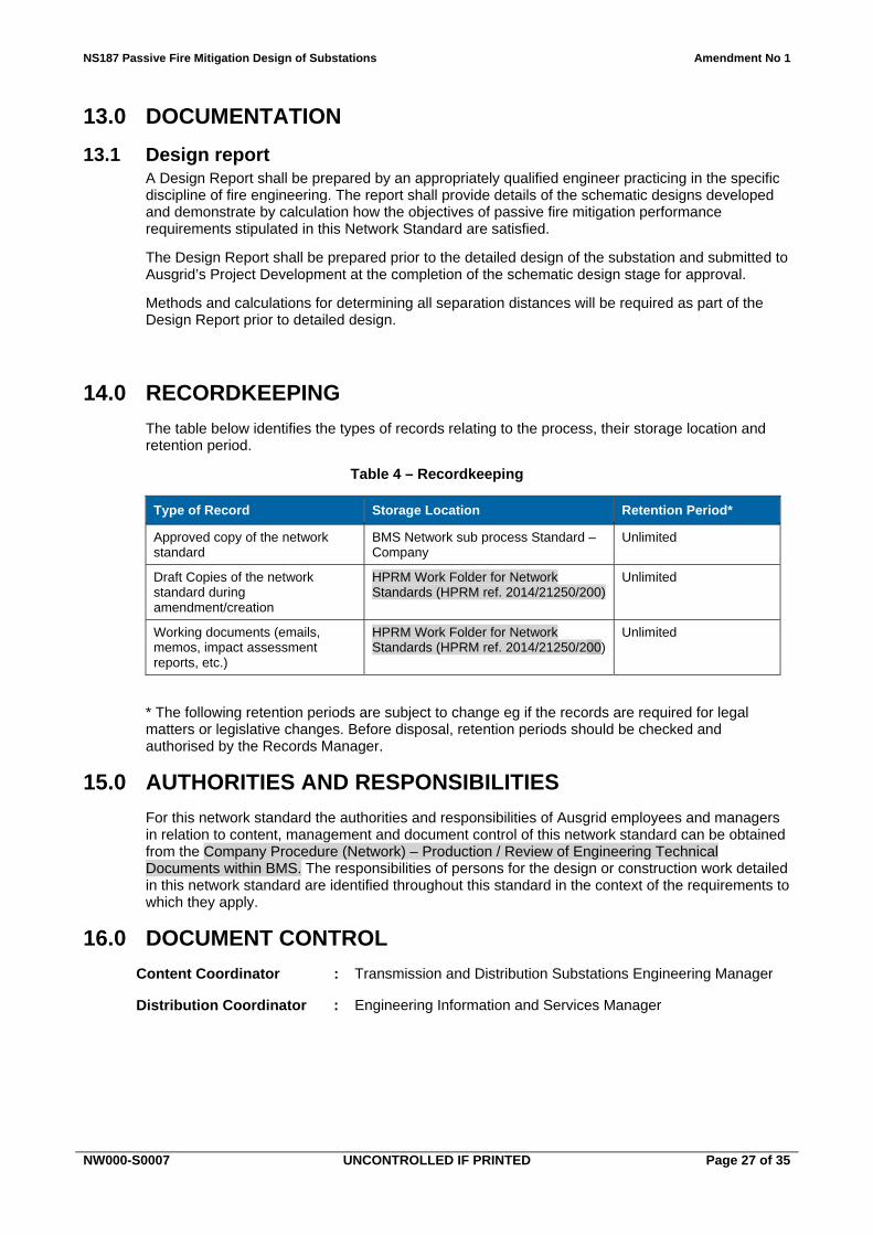
13.0 DOCUMENTATION
13.1 Design report A Design Report shall be prepared by an appropriately qualified engineer practicing in the specific discipline of fire engineering. The report shall provide details of the schematic designs developed and demonstrate by calculation how the objectives of passive fire mitigation performance requirements stipulated in this Network Standard are satisfied.
The Design Report shall be prepared prior to the detailed design of the substation and submitted to Ausgrid’s Project Development at the completion of the schematic design stage for approval.
Methods and calculations for determining all separation distances will be required as part of the Design Report prior to detailed design.
14.0 RECORDKEEPING
The table below identifies the types of records relating to the process, their storage location and retention period.
Table 4 – Recordkeeping
Type of Record Storage Location Retention Period*
Approved copy of the network standard
BMS Network sub process Standard – Company
Unlimited
Draft Copies of the network standard during amendment/creation
HPRM Work Folder for Network Standards (HPRM ref. 2014/21250/200)
Unlimited
Working documents (emails, memos, impact assessment reports, etc.)
HPRM Work Folder for Network Standards (HPRM ref. 2014/21250/200)
Unlimited
* The following retention periods are subject to change eg if the records are required for legal matters or legislative changes. Before disposal, retention periods should be checked and authorised by the Records Manager.
15.0 AUTHORITIES AND RESPONSIBILITIES
For this network standard the authorities and responsibilities of Ausgrid employees and managers in relation to content, management and document control of this network standard can be obtained from the Company Procedure (Network) – Production / Review of Engineering Technical Documents within BMS. The responsibilities of persons for the design or construction work detailed in this network standard are identified throughout this standard in the context of the requirements to which they apply.
16.0 DOCUMENT CONTROL
Content Coordinator : Transmission and Distribution Substations Engineering Manager
Distribution Coordinator : Engineering Information and Services Manager
NS187 Passive Fire Mitigation Design of Substations Amendment No 1
NW000-S0007 UNCONTROLLED IF PRINTED Page 28 of 35
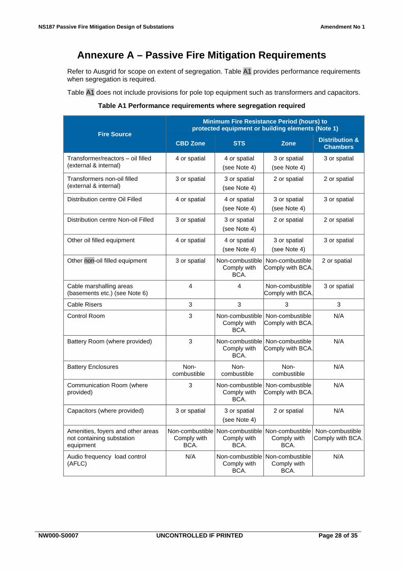
Annexure A – Passive Fire Mitigation Requirements
Refer to Ausgrid for scope on extent of segregation. Table A1 provides performance requirements when segregation is required.
Table A1 does not include provisions for pole top equipment such as transformers and capacitors.
Table A1 Performance requirements where segregation required
Fire Source
Minimum Fire Resistance Period (hours) to protected equipment or building elements (Note 1)
Distribution centre Oil Filled 4 or spatial 4 or spatial
(see Note 4)
3 or spatial
(see Note 4)
3 or spatial
Distribution centre Non-oil Filled 3 or spatial 3 or spatial
(see Note 4)
2 or spatial 2 or spatial
Other oil filled equipment 4 or spatial 4 or spatial
(see Note 4)
3 or spatial
(see Note 4)
3 or spatial
Other non-oil filled equipment 3 or spatial Non-combustible Comply with
BCA.
Non-combustible Comply with BCA.
2 or spatial
Cable marshalling areas (basements etc.) (see Note 6)
4 4 Non-combustible Comply with BCA.
3 or spatial
Cable Risers 3 3 3 3
Control Room 3 Non-combustible Comply with
BCA.
Non-combustible Comply with BCA.
N/A
Battery Room (where provided) 3 Non-combustible Comply with
BCA.
Non-combustible Comply with BCA.
N/A
Battery Enclosures Non-combustible
Non-combustible
Non-combustible
N/A
Communication Room (where provided)
3 Non-combustible Comply with
BCA.
Non-combustible Comply with BCA.
N/A
Capacitors (where provided) 3 or spatial 3 or spatial
(see Note 4)
2 or spatial N/A
Amenities, foyers and other areas not containing substation equipment
Non-combustible Comply with
BCA.
Non-combustible Comply with
BCA.
Non-combustible Comply with
BCA.
Non-combustible Comply with BCA.
Audio frequency load control (AFLC)
N/A Non-combustible Comply with
BCA.
Non-combustible Comply with
BCA.
N/A
NS187 Passive Fire Mitigation Design of Substations Amendment No 1
NW000-S0007 UNCONTROLLED IF PRINTED Page 29 of 35
Notes:
1. Higher fire resistant periods may be required under the BCA particularly where multi classifications exist when a substation is incorporated within another building.
2. AS 2067 – Substations and high voltage installations exceeding 1kV a.c. may have additional requirements for fire protection where a fire hazard exists.
3. Spatial separation shall only be applied in outdoor applications.
4. The required fire resistance period associated with external power transformers, external capacitors and other external oil filled equipment may be reduced to a minimum of 2 hours where the fire exposure can be demonstrated to reduce significantly during the fire resistance period (e.g. due to fuel limitation, bund drainage etc.).
5. Ausgrid may require a higher fire resistant period than those nominated in Table A1 for specific sites where loss of supply and/or safety issues dictate.
6. Refer to Annexure C for further discussion on the fire resistance period of cable marshalling areas. Refer to NS171 Firestopping in Substations for firestopping of penetrations and additional measures for cable fire protection.
NS187 Passive Fire Mitigation Design of Substations Amendment No 1
NW000-S0007 UNCONTROLLED IF PRINTED Page 30 of 35
Annexure B – Typical Properties of Combustible Liquids
Table B1 below provides information on the typical properties and characteristics of combustible liquids commonly associated with Ausgrid substations.
Table B1 Properties and characteristics of combustible liquids
Material / Liquid
Property Characteristic
Boiling Point
oC
Minimum
Flash Point oC
Fire Point
oC
Fire Class
IEC 61100
Ignition Time
Smoke Production
Heat Release
1. Transformers
Mineral Oil 140 170 O Short High High
Natural Ester - FR3 >300 >340 K2 Long Medium Medium
Synthetic Ester – MIDEL 7131
275 322 K3 Long Low Medium
Polyol Ester – VG32
269 Long Low Medium
Silicone Liquid – KF96-50CS
>310 >370 K Long Low Low
2. Capacitors
Jarylec – C101 144 154 Short
Faradol - 810 270 138 Short
The fire class “K Classification” used above is based on IEC 61039 Ed. 2.0 Classification of insulating liquids as indicated in Table B2 below:
Table B2 Fire point and calorific values of insulating liquids
Class Fire Point Class Calorific Value
O <= 300 oC 1 >= 42MJ/kg
K > 300 oC 2 32 < CV < 42 MJ/kg
L In Flammable 3 < 32MJ/kg
NS187 Passive Fire Mitigation Design of Substations Amendment No 1
NW000-S0007 UNCONTROLLED IF PRINTED Page 31 of 35
Annexure C – Background Information Relating to Passive Fire Protection
C.1 General
This Annexure provides general background information relating to some specific design approaches that have been adopted by Ausgrid for passive fire protection at substations.
C.2 Cable marshalling areas
Previous versions of NS187 required a fire resistance period (FRP) of 3 to 4 hours for all cable marshalling areas (CMA) in Annexure A. For many substations this would often exceed the minimum BCA requirements for the building overall.
Historically, the FRP requirements for CMA's were driven by a number of potential hazards that adversely impacted on fire risk, including:
1. The use of oil filled and oil impregnated HV cables in the CMA.
2. The use of oil filled switchgear in the switchroom directly above the CMA.
3. Small and confined basement areas with limited internal space for physical separation of cables.
4. Congested HV cable paths with multiple cable crossovers.
5. A prevalence of HV cable joints with inadequate separation to other cables and negligible cable fire protection.
Today, these potential hazards have been significantly reduced through the use of modern substation equipment and designs, the adoption of XLPE HV cable materials and the selective application of cable fire protection.
For modular buildings, the CMA is also open on all sides and this would effectively prevent the build-up of smoke and heat from a potential fire event.
Overall, the internal building fire risk for the CMA has been reduced to the point where a significant FRP is no longer considered to be necessary other than at critical locations (CBD, STS) or where required by the BCA. This change has now been incorporated into Annexure A of this Network Standard.
In addition, the treatment of penetrations through the various building elements can be correspondingly reduced to comply with the revised requirements of NS171 Firestopping in Substations, the BCA and AS 2067 Substations and high voltage installations exceeding 1kV a.c. where appropriate.
At locations where the residual fire risk is considered to be significant (e.g. major LV cables, highly congested HV crossovers), the Designer can chose to apply local cable fire protection as outlined in NS171.
C.3 Oil containment bund drainage
For oil pool fires this Network Standard requires that oil containment bunds which are provided with gravity drainage shall be assumed to function as designed. In this regard, any oil which is spilt within the bund shall be assumed to drain away via the flame trap and pipeline at the design flowrate.
For this to occur in practice the oil containment bund drainage system must be kept clean and in good working order. Routine inspection and clean-out of the oil containment flame traps, pipelines and EGOWS tanks is essential.
Refer to NS190 Oil Containment Operational Requirements for Major Substations for the Ausgrid requirements relating to the operation and maintenance of the various oil containment systems.
NS187 Passive Fire Mitigation Design of Substations Amendment No 1
NW000-S0007 UNCONTROLLED IF PRINTED Page 32 of 35
It should be noted that gravity drainage of bunds is NOT provided for all oil containment systems. In particular, Parallel Plate Separator (PPS) systems rely on a closed (undrained) system which uses pumps to empty the bunds. For these closed drainage systems any spilt oil will be retained within the bund enclosure and hence would be potentially available as fuel for an oil pool fire.
C.4 Transformer bushings
This Network Standard recognises that the resin impregnated paper and solid porcelain bushings on new power transformers are potentially replaceable items if damaged. On this basis, specific protection from radiant heat due to fire is not required for these items. Where oil filled porcelain bushings are installed, further advice should be sought from Ausgrid Primary Systems.
Ausgrid uses resin-impregnated paper, porcelain clad bushings at 132kV and 66kV and retains an inventory of spare bushings for most of its major power transformers. Augrid’s 33kV and 11kV bushings are readily available from local suppliers. Replacement of damaged transformer bushings can be achieved within an acceptably short timeframe that would typically involve the following key steps:
Day 1 – removal of HV connections and part drainage of transformer oil Day 2 – removal of damaged bushings Day 3 – workshop modifications to bushing flanges and connectors if required Day 4 – installation of new bushings Day 5 – refill transformer with oil Day 6 – contingency day Day 7 – transformer testing Day 8 – transformer testing Day 9 – reconnection of HV bars and cables
Overall, the bushing replacement process involves 7 to 9 days of work using regular hours and depends on the amount of local modifications required.
Under emergency conditions, and using shiftwork, the work duration could be reasonably expected to reduce to 4 days or less, allowing for multiple crews working closely together.
The estimated capital cost for a complete set of new insulated bushings for a power transformer is approximately $40,000 (in 2016).
C.5 Transformer tank
This Network Standard allows for a permissible radiant heat flux exposure of up to 25 kW/m2 for adjacent power transformers exposed to a fire. This limit applies to the main transformer tank and other non-replaceable oil filled components, but excludes the transformer insulated bushings (Refer to Clause C.4).
For Ausgrid’s current 132kV and 33kV power transformer designs, this radiant heat limit enables the equipment to remain within the main limiting design temperatures, as indicated below:
1. Transformer HV Winding Temperature Rise: 900C
2. Transformer HV Winding Hotspot: 1400C
Reasonable (but still conservative) values were used for the key inputs including initial temperatures, fire duration, time to de-energisation and temperature gradients. Detailed power transformer data for the current designs was supplied by Ausgrid Primary Systems.
C.6 Response to major fires
During a major fire, the adjacent power transformers are likely to remain in service and will continue to be actively monitored by the protection system. Adverse effects caused by heat and smoke (e.g. conductor damage, flashover etc.) are rapidly detected and the protection system will trip the unit off-line as required.
NS187 Passive Fire Mitigation Design of Substations Amendment No 1
NW000-S0007 UNCONTROLLED IF PRINTED Page 33 of 35
Ausgrid’s Network Security has developed agreed response procedures in the event of catastrophic events, including major transformer fires. There is recognition that major power transformer fires are rare events, and that the insulated bushings of adjacent transformers are potentially replaceable items that can be changed over if damaged by radiant heat exposure.
Network Security advises that, in the event of a major power transformer fire, full de-energisation of the substation would typically occur within 30 minutes. A worst case scenario may increase this time to 1 hour, although this would be rare.
De-energisation of the substation is undertaken from the Network Control Room, following a site visit and confirmation by an Ausgrid Operator. Once de-energisation has been confirmed by the Operator on site, the Fire Brigade will then enter the substation and commence their attack on the fire.
During a major fire, the Fire Brigade has control of the site and its perimeter and will determine the safe approach distance and who can access the site. These controls will also apply to any Ausgrid representatives at the site.
NS187 Passive Fire Mitigation Design of Substations Amendment No 1
NW000-S0007 UNCONTROLLED IF PRINTED Page 34 of 35
Annexure D – Sample Compliance Checklist
NS187 Passive Fire Mitigation Design of Substations Amendment No 1