Abstract This document describes the Network Time Protocol (NTP), specifies its formal structure and summarizes information useful for its implementation. NTP provides the mechanisms to synchro- nize time and coordinate time distribution in a large, diverse internet operating at rates from mundane to lightwave. It uses a returnable-time design in which a distributed subnet of time servers operating in a self-organizing, hierarchical-master-slave configuration synchronizes local clocks within the subnet and to national time standards via wire or radio. The servers can also redistribute reference time via local routing algorithms and time daemons. Status of this Memo This RFC specifies an IAB standards track protocol for the Internet community and requests discussion and suggestions for improvements. Please refer to the current edition of the “IAB Official Protocol Standards” for the standardization state and status of this protocol. Distribution of this memo is unlimited. Keywords: network clock synchronization, standard time distribution, fault-tolerant architecture, maximum-likelihood estimation, disciplined oscillator, internet protocol, high-speed networks, formal specification. Network Time Protocol (Version 3) Specification, Implementation and Analysis Network Working Group David L. Mills Request for Comments: 1305 University of Delaware Obsoletes: RFC-1119, RFC-1059, RFC-958 March 1992
Transcript
Abstract
This document describes the Network Time Protocol (NTP), specifies its formal structure andsummarizes information useful for its implementation. NTP provides the mechanisms to synchro-nize time and coordinate time distribution in a large, diverse internet operating at rates from mundaneto lightwave. It uses a returnable-time design in which a distributed subnet of time servers operatingin a self-organizing, hierarchical-master-slave configuration synchronizes local clocks within thesubnet and to national time standards via wire or radio. The servers can also redistribute referencetime via local routing algorithms and time daemons.
Status of this Memo
This RFC specifies an IAB standards track protocol for the Internet community and requestsdiscussion and suggestions for improvements. Please refer to the current edition of the “IAB OfficialProtocol Standards” for the standardization state and status of this protocol. Distribution of thismemo is unlimited.
Keywords: network clock synchronization, standard time distribution, fault-tolerant architecture,maximum-likelihood estimation, disciplined oscillator, internet protocol, high-speed networks,formal specification.
Network Time Protocol (Version 3)Specification, Implementation and Analysis
Network Working Group David L. MillsRequest for Comments: 1305 University of DelawareObsoletes: RFC-1119, RFC-1059, RFC-958 March 1992
Preface
This document describes Version 3 of the Network Time Protocol (NTP). It supersedes Version 2of the protocol described in RFC-1119 dated September 1989. However, it neither changes theprotocol in any significant way nor obsoletes previous versions or existing implementations. Themain motivation for the new version is to refine the analysis and implementation models for newapplications at much higher network speeds to the gigabit-per-second regime and to provide for theenhanced stability, accuracy and precision required at such speeds. In particular, the sources of timeand frequency errors have been rigorously examined and error bounds established in order toimprove performance, provide a model for correctness assertions and indicate timekeeping qualityto the user. The revision also incorporates two new optional features, (1) an algorithm to combinethe offsets of a number of peer time servers in order to enhance accuracy and (2) improvedlocal-clock algorithms which allow the poll intervals on all synchronization paths to be substantiallyincreased in order to reduce network overhead. An overview of the changes, which are describedin detail in Appendix D, follows:
1. In Version 3 The local-clock algorithm has been overhauled to improve stability and accuracy.Appendix G presents a detailed mathematical model and design example which has been refinedwith the aid of feedback-control analysis and extensive simulation using data collected overordinary Internet paths. Section 5 of RFC-1119 on the NTP local clock has been completelyrewritten to describe the new algorithm. Since the new algorithm can result in message rates farbelow the old ones, it is highly recommended that they be used in new implementations. Notethat use of the new algorithm does not affect interoperability with previous versions or existingimplementations.
2. In Version 3 a new algorithm to combine the offsets of a number of peer time servers is presentedin Appendix F. This algorithm is modelled on those used by national standards laboratories tocombine the weighted offsets from a number of standard clocks to construct a syntheticlaboratory timescale more accurate than that of any clock separately. It can be used in an NTPimplementation to improve accuracy and stability and reduce errors due to asymmetric paths inthe Internet. The new algorithm has been simulated using data collected over ordinary Internetpaths and, along with the new local-clock algorithm, implemented and tested in the Fuzzballtime servers now running in the Internet. Note that use of the new algorithm does not affectinteroperability with previous versions or existing implementations.
3. Several inconsistencies and minor errors in previous versions have been corrected in Version3. The description of the procedures has been rewritten in pseudo-code augmented by Englishcommentary for clarity and to avoid ambiguity. Appendix I has been added to illustrateC-language implementations of the various filtering and selection algorithms suggested for NTP.Additional information is included in Section 5 and in Appendix E, which includes the tutorialmaterial formerly included in Section 2 of RFC-1119, as well as much new material clarifyingthe interpretation of timescales and leap seconds.
4. Minor changes have been made in the Version-3 local-clock algorithms to avoid problemsobserved when leap seconds are introduced in the UTC timescale and also to support an auxiliary
RFC-1305 Network Time Protocol (Version 3) March 1992
Mills Page ii
precision oscillator, such as a cesium clock or timing receiver, as a precision timebase. Inaddition, changes were made to some procedures described in Section 3 and in the clock-filterand clock-selection procedures described in Section 4. While these changes were made to correctminor bugs found as the result of experience and are recommended for new implementations,they do not affect interoperability with previous versions or existing implementations in otherthan minor ways (at least until the next leap second).
5. In Version 3 changes were made to the way delay, offset and dispersion are defined, calculatedand processed in order to reliably bound the errors inherent in the time-transfer procedures. Inparticular, the error accumulations were moved from the delay computation to the dispersioncomputation and both included in the clock filter and selection procedures. The clock-selectionprocedure was modified to remove the first of the two sorting/discarding steps and replace withan algorithm first proposed by Marzullo and later incorporated in the Digital Time Service.These changes do not significantly affect the ordinary operation of or compatibility with variousversions of NTP, but they do provide the basis for formal statements of correctness as describedin Appendix H.
RFC-1305 Network Time Protocol (Version 3) March 1992
RFC-1305 Network Time Protocol (Version 3) March 1992
Mills Page vii
1. Introduction
This document constitutes a formal specification of the Network Time Protocol (NTP) Version 3,which is used to synchronize timekeeping among a set of distributed time servers and clients. Itdefines the architectures, algorithms, entities and protocols used by NTP and is intended primarilyfor implementors. A companion document [MIL91a] summarizes the requirements, analyticalmodels, algorithmic analysis and performance under typical Internet conditions. Another document[MIL91b] describes the NTP timescale and its relationship to other standard timescales now in use.NTP was first described in RFC-958 [MIL85c], but has since evolved in significant ways,culminating in the most recent NTP Version 2 described in RFC-1119 [MIL89]. It is built on theInternet Protocol (IP) [DAR81a] and User Datagram Protocol (UDP) [POS80], which provide aconnectionless transport mechanism; however, it is readily adaptable to other protocol suites. NTPis evolved from the Time Protocol [POS83b] and the ICMP Timestamp message [DAR81b], but isspecifically designed to maintain accuracy and robustness, even when used over typical Internetpaths involving multiple gateways, highly dispersive delays and unreliable nets.
The service environment consists of the implementation model and service model described inSection 2. The implementation model is based on a multiple-process operating system architecture,although other architectures could be used as well. The service model is based on a returnable-timedesign which depends only on measured clock offsets, but does not require reliable messagedelivery. The synchronization subnet uses a self-organizing, hierarchical-master-slave configura-tion, with synchronization paths determined by a minimum-weight spanning tree. While multiplemasters (primary servers) may exist, there is no requirement for an election protocol.
NTP itself is described in Section 3. It provides the protocol mechanisms to synchronize time inprinciple to precisions in the order of nanoseconds while preserving a non-ambiguous date well intothe next century. The protocol includes provisions to specify the characteristics and estimate theerror of the local clock and the time server to which it may be synchronized. It also includesprovisions for operation with a number of mutually suspicious, hierarchically distributed primaryreference sources such as radio-synchronized clocks.
Section 4 describes algorithms useful for deglitching and smoothing clock-offset samples collectedon a continuous basis. These algorithms evolved from those suggested in [MIL85a], were refinedas the results of experiments described in [MIL85b] and further evolved under typical operatingconditions over the last three years. In addition, as the result of experience in operating multiple-server subnets including radio clocks at several sites in the U.S. and with clients in the U.S. andEurope, reliable algorithms for selecting good clocks from a population possibly including brokenones have been developed [DEC89], [MIL91a] and are described in Section 4.
The accuracies achievable by NTP depend strongly on the precision of the local-clock hardwareand stringent control of device and process latencies. Provisions must be included to adjust thesoftware logical-clock time and frequency in response to corrections produced by NTP. Section 5describes a local-clock design evolved from the Fuzzball implementation described in [MIL83b]and [MIL88b]. This design includes offset-slewing, frequency compensation and deglitching
RFC-1305 Network Time Protocol (Version 3) March 1992
Mills Page 1
mechanisms capable of accuracies in the order of a millisecond, even after extended periods whensynchronization to primary reference sources has been lost.
Details specific to NTP packet formats used with the Internet Protocol (IP) and User DatagramProtocol (UDP) are presented in Appendix A, while details of a suggested auxiliary NTP ControlMessage, which may be used when comprehensive network-monitoring facilities are not available,are presented in Appendix B. Appendix C contains specification and implementation details of anoptional authentication mechanism which can be used to control access and prevent unauthorizeddata modification, while Appendix D contains a listing of differences between Version 3 of NTPand previous versions. Appendix E expands on issues involved with precision timescales andcalendar dating peculiar to computer networks and NTP. Appendix F describes an optionalalgorithm to improve accuracy by combining the time offsets of a number of clocks. Appendix Gpresents a detailed mathematical model and analysis of the NTP local-clock algorithms. AppendixH analyzes the sources and propagation of errors and presents correctness principles relating to thetime-transfer service. Appendix I illustrates C-language code segments for the clock-filter, clock-selection and related algorithms described in Section 4.
1.1. Related Technology
Other mechanisms have been specified in the Internet protocol suite to record and transmit the timeat which an event takes place, including the Daytime protocol [POS83a], Time Protocol [POS83b],ICMP Timestamp message [DAR81b] and IP Timestamp option [SU81]. Experimental results onmeasured clock offsets and roundtrip delays in the Internet are discussed in [MIL83a], [MIL85b],[COL88] and [MIL88a]. Other synchronization algorithms are discussed in [LAM78], [GUS84],[HAL84], [LUN84], [LAM85], [MAR85], [MIL85a], [MIL85b], [MIL85c], [GUS85b], [SCH86],[TRI86], [RIC88], [MIL88a], [DEC89] and [MIL91a], while protocols based on them are describedin [MIL81a], [MIL81b], [MIL83b], [GUS85a], [MIL85c], [TRI86], [MIL88a], [DEC89] and[MIL91a]. NTP uses techniques evolved from them and both linear-systems and agreementmethodologies. Linear methods for digital telephone network synchronization are summarized in[LIN80], while agreement methods for clock synchronization are summarized in [LAM85].
The Digital Time Service (DTS) [DEC89] has many of the same service objectives as NTP. TheDTS design places heavy emphasis on configuration management and correctness principles whenoperated in a managed LAN or LAN-cluster environment, while NTP places heavy emphasis onthe accuracy and stability of the service operated in an unmanaged, global-internet environment. InDTS a synchronization subnet consists of clerks, servers, couriers and time providers. With respectto the NTP nomenclature, a time provider is a primary reference source, a courier is a secondaryserver intended to import time from one or more distant primary servers for local redistribution anda server is intended to provide time for possibly many end nodes or clerks. Unlike NTP, DTS doesnot need or use mode or stratum information in clock selection and does not include provisions tofilter timing noise, select the most accurate from a set of presumed correct clocks or compensatefor inherent frequency errors.
In fact, the latest revisions in NTP have adopted certain features of DTS in order to supportcorrectness principles. These include mechanisms to bound the maximum errors inherent in the
RFC-1305 Network Time Protocol (Version 3) March 1992
Mills Page 2
time-transfer procedures and the use of a provably correct (subject to stated assumptions) mecha-nism to reject inappropriate peers in the clock-selection procedures. These features are described inSection 4 and Appendix H of this document.
The Fuzzball routing protocol [MIL83b], sometimes called Hellospeak, incorporates time synchro-nization directly into the routing-protocol design. One or more processes synchronize to an externalreference source, such as a radio clock or NTP daemon, and the routing algorithm constructs aminimum-weight spanning tree rooted on these processes. The clock offsets are then distributedalong the arcs of the spanning tree to all processes in the system and the various process clockscorrected using the procedure described in Section 5 of this document. While it can be seen that thedesign of Hellospeak strongly influenced the design of NTP, Hellospeak itself is not an Internetprotocol and is unsuited for use outside its local-net environment.
The Unix 4.3bsd time daemon timed [GUS85a] uses a single master-time daemon to measure offsetsof a number of slave hosts and send periodic corrections to them. In this model the master isdetermined using an election algorithm [GUS85b] designed to avoid situations where either nomaster is elected or more than one master is elected. The election process requires a broadcastcapability, which is not a ubiquitous feature of the Internet. While this model has been extended tosupport hierarchical configurations in which a slave on one network serves as a master on the other[TRI86], the model requires handcrafted configuration tables in order to establish the hierarchy andavoid loops. In addition to the burdensome, but presumably infrequent, overheads of the electionprocess, the offset measurement/correction process requires twice as many messages as NTP perupdate.
A scheme with features similar to NTP is described in [KOP87]. This scheme is intended formulti-server LANs where each of a set of possibly many time servers determines its local-time offsetrelative to each of the other servers in the set using periodic timestamped messages, then determinesthe local-clock correction using the Fault-Tolerant Average (FTA) algorithm of [LUN84]. The FTAalgorithm, which is useful where up to k servers may be faulty, sorts the offsets, discards the khighest and lowest ones and averages the rest. The scheme, as described in [SCH86], is most suitableto LAN environments which support broadcast and would result in unacceptable overhead in aninternet environment. In addition, for reasons given in Section 4 of this paper, the statisticalproperties of the FTA algorithm are not likely to be optimal in an internet environment with highlydispersive delays.
A good deal of research has gone into the issue of maintaining accurate time in a community wheresome clocks cannot be trusted. A truechimer is a clock that maintains timekeeping accuracy to apreviously published (and trusted) standard, while a falseticker is a clock that does not. Determiningwhether a particular clock is a truechimer or falseticker is an interesting abstract problem which canbe attacked using agreement methods summarized in [LAM85] and [SRI87].
A convergence function operates upon the offsets between the clocks in a system to increase theaccuracy by reducing or eliminating errors caused by falsetickers. There are two classes ofconvergence functions, those involving interactive-convergence algorithms and those involvinginteractive-consistency algorithms. Interactive-convergence algorithms use statistical clustering
RFC-1305 Network Time Protocol (Version 3) March 1992
Mills Page 3
techniques such as the fault-tolerant average algorithm of [HAL84], the CNV algorithm of [LUN84],the majority-subset algorithm of [MIL85a], the non-Byzantine algorithm of [RIC88], the egocentricalgorithm of [SCH86], the intersection algorithm of [MAR85] and [DEC89] and the algorithms inSection 4 of this document.
Interactive-consistency algorithms are designed to detect faulty clock processes which mightindicate grossly inconsistent offsets in successive readings or to different readers. These algorithmsuse an agreement protocol involving successive rounds of readings, possibly relayed and possiblyaugmented by digital signatures. Examples include the fireworks algorithm of [HAL84] and theoptimum algorithm of [SRI87]. However, these algorithms require large numbers of messages,especially when large numbers of clocks are involved, and are designed to detect faults that haverarely been found in the Internet experience. For these reasons they are not considered further inthis document.
In practice it is not possible to determine the truechimers from the falsetickers on other than astatistical basis, especially with hierarchical configurations and a statistically noisy Internet. Whileit is possible to bound the maximum errors in the time-transfer procedures, assuming sufficientlygenerous tolerances are adopted for the hardware components, this generally results in rather pooraccuracies and stabilities. The approach taken in the NTP design and its predecessors involvesmutually coupled oscillators and maximum-likelihood estimation and clock-selection procedures,together with a design that allows provable assertions on error bounds to be made relative to statedassumptions on the correctness of the primary reference sources. From the analytical point of view,the system of distributed NTP peers operates as a set of coupled phase-locked oscillators, with theupdate algorithm functioning as a phase detector and the local clock as a disciplined oscillator, butwith deterministic error bounds calculated at each step in the time-transfer process.
The particular choice of offset measurement and computation procedure described in Section 3 isa variant of the returnable-time system used in some digital telephone networks [LIN80]. The clockfilter and selection algorithms are designed so that the clock synchronization subnet self-organizesinto a hierarchical-master-slave configuration [MIT80]. With respect to timekeeping accuracy andstability, the similarity of NTP to digital telephone systems is not accidental, since systems like thishave been studied extensively [LIN80], [BRA80]. What makes the NTP model unique is theadaptive configuration, polling, filtering, selection and correctness mechanisms which tailor thedynamics of the system to fit the ubiquitous Internet environment.
2. System Architecture
In the NTP model a number of primary reference sources, synchronized by wire or radio to nationalstandards, are connected to widely accessible resources, such as backbone gateways, and operatedas primary time servers. The purpose of NTP is to convey timekeeping information from theseservers to other time servers via the Internet and also to cross-check clocks and mitigate errors dueto equipment or propagation failures. Some number of local-net hosts or gateways, acting assecondary time servers, run NTP with one or more of the primary servers. In order to reduce theprotocol overhead, the secondary servers distribute time via NTP to the remaining local-net hosts.In the interest of reliability, selected hosts can be equipped with less accurate but less expensive
RFC-1305 Network Time Protocol (Version 3) March 1992
Mills Page 4
radio clocks and used for backup in case of failure of the primary and/or secondary servers orcommunication paths between them.
Throughout this document a standard nomenclature has been adopted: the stability of a clock is howwell it can maintain a constant frequency, the accuracy is how well its frequency and time comparewith national standards and the precision is how precisely these quantities can be maintained withina particular timekeeping system. Unless indicated otherwise, the offset of two clocks is the timedifference between them, while the skew is the frequency difference (first derivative of offset withtime) between them. Real clocks exhibit some variation in skew (second derivative of offset withtime), which is called drift; however, in this version of the specification the drift is assumed zero.
NTP is designed to produce three products: clock offset, roundtrip delay and dispersion, all of whichare relative to a selected reference clock. Clock offset represents the amount to adjust the local clockto bring it into correspondence with the reference clock. Roundtrip delay provides the capability tolaunch a message to arrive at the reference clock at a specified time. Dispersion represents themaximum error of the local clock relative to the reference clock. Since most host time servers willsynchronize via another peer time server, there are two components in each of these three products,those determined by the peer relative to the primary reference source of standard time and thosemeasured by the host relative to the peer. Each of these components are maintained separately inthe protocol in order to facilitate error control and management of the subnet itself. They providenot only precision measurements of offset and delay, but also definitive maximum error bounds, sothat the user interface can determine not only the time, but the quality of the time as well.
There is no provision for peer discovery or virtual-circuit management in NTP. Data integrity isprovided by the IP and UDP checksums. No flow-control or retransmission facilities are providedor necessary. Duplicate detection is inherent in the processing algorithms. The service can operatein a symmetric mode, in which servers and clients are indistinguishable, yet maintain a small amountof state information, or in client/server mode, in which servers need maintain no state other thanthat contained in the client request. A lightweight association-management capability, includingdynamic reachability and variable poll-rate mechanisms, is included only to manage the stateinformation and reduce resource requirements. Since only a single NTP message format is used,the protocol is easily implemented and can be used in a variety of solicited or unsolicited pollingmechanisms.
It should be recognized that clock synchronization requires by its nature long periods and multiplecomparisons in order to maintain accurate timekeeping. While only a few measurements are usuallyadequate to reliably determine local time to within a second or so, periods of many hours and dozensof measurements are required to resolve oscillator skew and maintain local time to the order of amillisecond. Thus, the accuracy achieved is directly dependent on the time taken to achieve it.Fortunately, the frequency of measurements can be quite low and almost always non-intrusive tonormal net operations.
RFC-1305 Network Time Protocol (Version 3) March 1992
Mills Page 5
2.1. Implementation Model
In what may be the most common client/server model a client sends an NTP message to one or moreservers and processes the replies as received. The server interchanges addresses and ports, overwritescertain fields in the message, recalculates the checksum and returns the message immediately.Information included in the NTP message allows the client to determine the server time with respectto local time and adjust the local clock accordingly. In addition, the message includes informationto calculate the expected timekeeping accuracy and reliability, as well as select the best from possiblyseveral servers.
While the client/server model may suffice for use on local nets involving a public server and perhapsmany workstation clients, the full generality of NTP requires distributed participation of a numberof client/servers or peers arranged in a dynamically reconfigurable, hierarchically distributedconfiguration. It also requires sophisticated algorithms for association management, data manipu-lation and local-clock control. Throughout the remainder of this document the term host refers toan instantiation of the protocol on a local processor, while the term peer refers to the instantiationof the protocol on a remote processor connected by a network path.
Figure 1 shows an implementation model for a host including three processes sharing a partitioneddata base, with a partition dedicated to each peer, and interconnected by a message-passing system.The transmit process, driven by independent timers for each peer, collects information in the database and sends NTP messages to the peers. Each message contains the local timestamp when themessage is sent, together with previously received timestamps and other information necessary todetermine the hierarchy and manage the association. The message transmission rate is determinedby the accuracy required of the local clock, as well as the accuracies of its peers.
The receive process receives NTP messages and perhaps messages in other protocols, as well asinformation from directly connected radio clocks. When an NTP message is received, the offsetbetween the peer clock and the local clock is computed and incorporated into the data base along
UpdateProcedure
ReceiveProcess
Local ClockProcess
TransmitProcess
Network
Figure 1. Implementation Model
RFC-1305 Network Time Protocol (Version 3) March 1992
Mills Page 6
with other information useful for error determination and peer selection. A filtering algorithmdescribed in Section 4 improves the accuracy by discarding inferior data.
The update procedure is initiated upon receipt of a message and at other times. It processes the offsetdata from each peer and selects the best one using the algorithms of Section 4. This may involvemany observations of a few peers or a few observations of many peers, depending on the accuraciesrequired.
The local-clock process operates upon the offset data produced by the update procedure and adjuststhe phase and frequency of the local clock using the mechanisms described in Section 5. This mayresult in either a step-change or a gradual phase adjustment of the local clock to reduce the offsetto zero. The local clock provides a stable source of time information to other users of the systemand for subsequent reference by NTP itself.
2.2. Network Configurations
The synchronization subnet is a connected network of primary and secondary time servers, clientsand interconnecting transmission paths. A primary time server is directly synchronized to a primaryreference source, usually a radio clock. A secondary time server derives synchronization, possiblyvia other secondary servers, from a primary server over network paths possibly shared with otherservices. Under normal circumstances it is intended that the synchronization subnet of primary andsecondary servers assumes a hierarchical-master-slave configuration with the primary servers at theroot and secondary servers of decreasing accuracy at successive levels toward the leaves.
Following conventions established by the telephone industry [BEL86], the accuracy of each serveris defined by a number called the stratum, with the topmost level (primary servers) assigned as oneand each level downwards (secondary servers) in the hierarchy assigned as one greater than thepreceding level. With current technology and available radio clocks, single-sample accuracies inthe order of a millisecond can be achieved at the network interface of a primary server. Accuraciesof this order require special care in the design and implementation of the operating system and thelocal-clock mechanism, such as described in Section 5.
As the stratum increases from one, the single-sample accuracies achievable will degrade dependingon the network paths and local-clock stabilities. In order to avoid the tedious calculations [BRA80]necessary to estimate errors in each specific configuration, it is useful to assume the meanmeasurement errors accumulate approximately in proportion to the measured delay and dispersionrelative to the root of the synchronization subnet. Appendix H contains an analysis of errors,including a derivation of maximum error as a function of delay and dispersion, where the latterquantity depends on the precision of the timekeeping system, frequency tolerance of the local clockand various residuals. Assuming the primary servers are synchronized to standard time withinknown accuracies, this provides a reliable, determistic specification on timekeeping accuraciesthroughout the synchronization subnet.
Again drawing from the experience of the telephone industry, which learned such lessons atconsiderable cost [ABA89], the synchronization subnet topology should be organized to producethe highest accuracy, but must never be allowed to form a loop. An additional factor is that each
RFC-1305 Network Time Protocol (Version 3) March 1992
Mills Page 7
increment in stratum involves a potentially unreliable time server which introduces additionalmeasurement errors. The selection algorithm used in NTP uses a variant of the Bellman-Forddistributed routing algorithm [37] to compute the minimum-weight spanning trees rooted on theprimary servers. The distance metric used by the algorithm consists of the (scaled) stratum plus thesynchronization distance, which itself consists of the dispersion plus one-half the absolute delay.Thus, the synchronization path will always take the minimum number of servers to the root, withties resolved on the basis of maximum error.
As a result of this design, the subnet reconfigures automatically in a hierarchical-master-slaveconfiguration to produce the most accurate and reliable time, even when one or more primary orsecondary servers or the network paths between them fail. This includes the case where all normalprimary servers (e.g., highly accurate WWVB radio clock operating at the lowest synchronizationdistances) on a possibly partitioned subnet fail, but one or more backup primary servers (e.g., lessaccurate WWV radio clock operating at higher synchronization distances) continue operation.However, should all primary servers throughout the subnet fail, the remaining secondary serverswill synchronize among themselves while distances ratchet upwards to a preselected maximum“infinity” due to the well-known properties of the Bellman-Ford algorithm. Upon reaching themaximum on all paths, a server will drop off the subnet and free-run using its last determined timeand frequency. Since these computations are expected to be very precise, especially in frequency,even extended outage periods can result in timekeeping errors not greater than a few millisecondsper day with appropriately stabilized oscillators (see Section 5).
In the case of multiple primary servers, the spanning-tree computation will usually select the serverat minimum synchronization distance. However, when these servers are at approximately the samedistance, the computation may result in random selections among them as the result of normaldispersive delays. Ordinarily, this does not degrade accuracy as long as any discrepancy betweenthe primary servers is small compared to the synchronization distance. If not, the filter and selectionalgorithms will select the best of the available servers and cast out outlyers as intended.
3. Network Time Protocol
This section consists of a formal definition of the Network Time Protocol, including its data formats,entities, state variables, events and event-processing procedures. The specification is based on theimplementation model illustrated in Figure 1, but it is not intended that this model is the only oneupon which a specification can be based. In particular, the specification is intended to illustrate andclarify the intrinsic operations of NTP, as well as to serve as a foundation for a more rigorous,comprehensive and verifiable specification.
3.1. Data Formats
All mathematical operations expressed or implied herein are in two’s-complement, fixed-pointarithmetic. Data are specified as integer or fixed-point quantities, with bits numbered in big-endianfashion from zero starting at the left, or high-order, position. Since various implementations mayscale externally derived quantities for internal use, neither the precision nor decimal-point placementfor fixed-point quantities is specified. Unless specified otherwise, all quantities are unsigned and
RFC-1305 Network Time Protocol (Version 3) March 1992
Mills Page 8
may occupy the full field width with an implied zero preceding bit zero. Hardware and softwarepackages designed to work with signed quantities will thus yield surprising results when the mostsignificant (sign) bit is set. It is suggested that externally derived, unsigned fixed-point quantitiessuch as timestamps be shifted right one bit for internal use, since the precision represented by thefull field width is seldom justified.
Since NTP timestamps are cherished data and, in fact, represent the main product of the protocol,a special timestamp format has been established. NTP timestamps are represented as a 64-bitunsigned fixed-point number, in seconds relative to 0h on 1 January 1900. The integer part is in thefirst 32 bits and the fraction part in the last 32 bits. This format allows convenient multiple-precisionarithmetic and conversion to Time Protocol representation (seconds), but does complicate theconversion to ICMP Timestamp message representation (milliseconds). The precision of thisrepresentation is about 200 picoseconds, which should be adequate for even the most exoticrequirements.
Timestamps are determined by copying the current value of the local clock to a timestamp whensome significant event, such as the arrival of a message, occurs. In order to maintain the highestaccuracy, it is important that this be done as close to the hardware or software driver associated withthe event as possible. In particular, departure timestamps should be redetermined for each link-levelretransmission. In some cases a particular timestamp may not be available, such as when the hostis rebooted or the protocol first starts up. In these cases the 64-bit field is set to zero, indicating thevalue is invalid or undefined.
Note that since some time in 1968 the most significant bit (bit 0 of the integer part) has been set andthat the 64-bit field will overflow some time in 2036. Should NTP be in use in 2036, some externalmeans will be necessary to qualify time relative to 1900 and time relative to 2036 (and othermultiples of 136 years). Timestamped data requiring such qualification will be so precious thatappropriate means should be readily available. There will exist an 200-picosecond interval,henceforth ignored, every 136 years when the 64-bit field will be zero and thus considered invalid.
3.2. State Variables and Parameters
Following is a summary of the various state variables and parameters used by the protocol. Theyare separated into classes of system variables, which relate to the operating system environment andlocal-clock mechanism; peer variables, which represent the state of the protocol machine specificto each peer; packet variables, which represent the contents of the NTP message; and parameters,which represent fixed configuration constants for all implementations of the current version. Foreach class the description of the variable is followed by its name and the procedure or value whichcontrols it. Note that variables are in lower case, while parameters are in upper case. Additionaldetails on formats and use are presented in later sections and Appendices.
3.2.1. Common Variables
The following variables are common to two or more of the system, peer and packet classes.Additional variables are specific to the optional authentication mechanism as described in Appendix
RFC-1305 Network Time Protocol (Version 3) March 1992
Mills Page 9
C. When necessary to distinguish between common variables of the same name, the variableidentifier will be used.
Peer Address (peer.peeraddr, pkt.peeraddr), Peer Port (peer.peerport, pkt.peerport): These are the32-bit Internet address and 16-bit port number of the peer.
Host Address (peer.hostaddr, pkt.hostaddr), Host Port (peer.hostport, pkt.hostport): These are the32-bit Internet address and 16-bit port number of the host. They are included among the statevariables to support multi-homing.
Leap Indicator (sys.leap, peer.leap, pkt.leap): This is a two-bit code warning of an impending leapsecond to be inserted in the NTP timescale. The bits are set before 23:59 on the day of insertionand reset after 00:00 on the following day. This causes the number of seconds (rollover interval)in the day of insertion to be increased or decreased by one. In the case of primary servers thebits are set by operator intervention, while in the case of secondary servers the bits are set bythe protocol. The two bits, bit 0 and bit 1, respectively, are coded as follows:
00 no warning01 last minute has 61 seconds10 last minute has 59 seconds11 alarm condition (clock not synchronized)
In all except the alarm condition (112), NTP itself does nothing with these bits, except pass themon to the time-conversion routines that are not part of NTP. The alarm condition occurs when,for whatever reason, the local clock is not synchronized, such as when first coming up or afteran extended period when no primary reference source is available.
Mode (peer.mode, pkt.mode): This is an integer indicating the association mode, with values codedas follows:
0 unspecified1 symmetric active2 symmetric passive3 client4 server5 broadcast6 reserved for NTP control messages7 reserved for private use
Stratum (sys.stratum, peer.stratum, pkt.stratum): This is an integer indicating the stratum of the localclock, with values defined as follows:
RFC-1305 Network Time Protocol (Version 3) March 1992
Mills Page 10
For comparison purposes a value of zero is considered greater than any other value. Note thatthe maximum value of the integer encoded as a packet variable is limited by the parameterNTP.MAXSTRATUM.
Poll Interval (sys.poll, peer.hostpoll, peer.peerpoll, pkt.poll): This is a signed integer indicating theminimum interval between transmitted messages, in seconds as a power of two. For instance, avalue of six indicates a minimum interval of 64 seconds.
Precision (sys.precision, peer.precision, pkt.precision): This is a signed integer indicating theprecision of the various clocks, in seconds to the nearest power of two. The value must berounded to the next larger power of two; for instance, a 50-Hz (20 ms) or 60-Hz (16.67 ms)power-frequency clock would be assigned the value -5 (31.25 ms), while a 1000-Hz (1 ms)crystal-controlled clock would be assigned the value -9 (1.95 ms).
Root Delay (sys.rootdelay, peer.rootdelay, pkt.rootdelay): This is a signed fixed-point numberindicating the total roundtrip delay to the primary reference source at the root of the synchroni-zation subnet, in seconds. Note that this variable can take on both positive and negative values,depending on clock precision and skew.
Root Dispersion (sys.rootdispersion, peer.rootdispersion, pkt.rootdispersion): This is a signedfixed-point number indicating the maximum error relative to the primary reference source at theroot of the synchronization subnet, in seconds. Only positive values greater than zero arepossible.
Reference Clock Identifier (sys.refid, peer.refid, pkt.refid): This is a 32-bit code identifying theparticular reference clock. In the case of stratum 0 (unspecified) or stratum 1 (primary referencesource), this is a four-octet, left-justified, zero-padded ASCII string, for example (see AppendixA for comprehensive list):
In the case of stratum 2 and greater (secondary reference) this is the four-octet Internet addressof the peer selected for synchronization.
Reference Timestamp (sys.reftime, peer.reftime, pkt.reftime): This is the local time, in timestampformat, when the local clock was last updated. If the local clock has never been synchronized,the value is zero.
RFC-1305 Network Time Protocol (Version 3) March 1992
Mills Page 11
Originate Timestamp (peer.org, pkt.org): This is the local time, in timestamp format, at the peerwhen its latest NTP message was sent. If the peer becomes unreachable the value is set to zero.
Receive Timestamp (peer.rec, pkt.rec): This is the local time, in timestamp format, when the latestNTP message from the peer arrived. If the peer becomes unreachable the value is set to zero.
Transmit Timestamp (peer.xmt, pkt.xmt): This is the local time, in timestamp format, at which theNTP message departed the sender.
3.2.2. System Variables
Table 1 shows the complete set of system variables. In addition to the common variables describedpreviously, the following variables are used by the operating system in order to synchronize thelocal clock.
Local Clock (sys.clock): This is the current local time, in timestamp format. Local time is derivedfrom the hardware clock of the particular machine and increments at intervals depending on thedesign used. An appropriate design, including slewing and skew-Compensation mechanisms,is described in Section 5.
Clock Source (sys.peer): This is a selector identifying the current synchronization source. Usuallythis will be a pointer to a structure containing the peer variables. The special value NULLindicates there is no currently valid synchronization source.
3.2.3. Peer Variables
Table 2 shows the complete set of peer variables. In addition to the common variables describedpreviously, the following variables are used by the peer management and measurement functions.
Configured Bit (peer.config): This is a bit indicating that the association was created fromconfiguration information and should not be demobilized if the peer becomes unreachable.
RFC-1305 Network Time Protocol (Version 3) March 1992
Mills Page 12
Update Timestamp (peer.update): This is the local time, in timestamp format, when the most recentNTP message was received. It is used in calculating the skew dispersion.
Reachability Register (peer.reach): This is a shift register of NTP.WINDOW bits used to determinethe reachability status of the peer, with bits entering from the least significant (rightmost) end.A peer is considered reachable if at least one bit in this register is set to one.
poll updateFilter Register peer.filter filterValid Data Counter peer.valid transmitDelay peer.delay filterOffset peer.offset filterDispersion peer.dispersion filterAuthentic Enable Bit peer.authenable authenticationAuthenticated Bit peer.authentic authenticationHost Key Identifier peer.hostkeyid authenticationPeer Key Identifier peer.peerkeyid authentication
Table 2. Peer Variables
RFC-1305 Network Time Protocol (Version 3) March 1992
Mills Page 13
Peer Timer (peer.timer): This is an integer counter used to control the interval between transmittedNTP messages. Once set to a nonzero value, the counter decrements at one-second intervalsuntil reaching zero, at which time the transmit procedure is called. Note that the operation ofthis timer is independent of local-clock updates, which implies that the timekeeping system andinterval-timer system architecture must be independent of each other.
3.2.4. Packet Variables
Table 3 shows the complete set of packet variables. In addition to the common variables describedpreviously, the following variables are defined.
Version Number (pkt.version): This is an integer indicating the version number of the sender. NTPmessages will always be sent with the current version number NTP.VERSION and will alwaysbe accepted if the version number matches NTP.VERSION. Exceptions may be advised on acase-by-case basis at times when the version number is changed. Specific guidelines forinteroperation between this version and previous versions of NTP are summarized in AppendixD.
3.2.5. Clock-Filter Variables
When the filter and selection algorithms suggested in Section 4 are used, the following state variablesare defined in addition to the variables described previously.
RFC-1305 Network Time Protocol (Version 3) March 1992
Mills Page 14
Filter Register (peer.filter): This is a shift register of NTP.SHIFT stages, where each stage stores a3-tuple consisting of the measured delay, measured offset and calculated dispersion associatedwith a single observation. These 3-tuples enter from the most significant (leftmost) right andare shifted towards the least significant (rightmost) end and eventually discarded as newobservations arrive.
Valid Data Counter (peer.valid): This is an integer counter indicating the valid samples remainingin the filter register. It is used to determine the reachability state and when the poll intervalshould be increased or decreased.
Offset (peer.offset): This is a signed, fixed-point number indicating the offset of the peer clockrelative to the local clock, in seconds.
Delay (peer.delay): This is a signed fixed-point number indicating the roundtrip delay of the peerclock relative to the local clock over the network path between them, in seconds. Note that thisvariable can take on both positive and negative values, depending on clock precision andskew-error accumulation.
Dispersion (peer.dispersion): This is a signed fixed-point number indicating the maximum error ofthe peer clock relative to the local clock over the network path between them, in seconds. Onlypositive values greater than zero are possible.
3.2.6. Authentication Variables
When the authentication mechanism suggested in Appendix C is used, the following state variablesare defined in addition to the variables described previously. These variables are used only if theoptional authentication mechanism described in Appendix C is implemented.
Authentication Enabled Bit (peer.authenable): This is a bit indicating that the association is tooperate in the authenticated mode.
Authenticated Bit (peer.authentic): This is a bit indicating that the last message received from thepeer has been correctly authenticated.
Key Identifier (peer.hostkeyid, peer.peerkeyid, pkt.keyid): This is an integer identifying thecryptographic key used to generate the message-authentication code.
Cryptographic Keys (sys.key): This is a set of 64-bit DES keys. Each key is constructed as in theBerkeley Unix distributions, which consists of eight octets, where the seven low-order bits ofeach octet correspond to the DES bits 1-7 and the high-order bit corresponds to the DESodd-parity bit 8.
Crypto-Checksum (pkt.check): This is a crypto-checksum computed by the encryption procedure.
3.2.7. Parameters
Table 4 shows the parameters assumed for all implementations operating in the Internet system. Itis necessary to agree on the values for these parameters in order to avoid unnecessary network
RFC-1305 Network Time Protocol (Version 3) March 1992
Mills Page 15
overheads and stable peer associations. The following parameters are assumed fixed and applicableto all associations.
Version Number (NTP.VERSION): This is the current NTP version number (3).
NTP Port (NTP.PORT): This is the port number (123) assigned by the Internet Assigned NumbersAuthority to NTP.
Maximum Stratum (NTP.MAXSTRATUM): This is the maximum stratum value that can beencoded as a packet variable, also interpreted as “infinity” or unreachable by the subnet routingalgorithm.
Maximum Clock Age (NTP.MAXAGE): This is the maximum interval a reference clock will beconsidered valid after its last update, in seconds.
Maximum Skew (NTP.MAXSKEW): This is the maximum offset error due to skew of the localclock over the interval determined by NTP.MAXAGE, in seconds. The ratio
ϕ = NTP.MAXSKEWNTP.MAXAGE
is interpreted as the maximum possible skew rate due to all causes.
Maximum Distance (NTP.MAXDISTANCE): When the selection algorithm suggested in Section4 is used, this is the maximum synchronization distance for peers acceptable for synchronization.
Minimum Poll Interval (NTP.MINPOLL): This is the minimum poll interval allowed by any peerof the Internet system, in seconds to a power of two.
RFC-1305 Network Time Protocol (Version 3) March 1992
Mills Page 16
Maximum Poll Interval (NTP.MAXPOLL): This is the maximum poll interval allowed by any peerof the Internet system, in seconds to a power of two.
Minimum Select Clocks (NTP.MINCLOCK): When the selection algorithm suggested in Section4 is used, this is the minimum number of peers acceptable for synchronization.
Maximum Select Clocks (NTP.MAXCLOCK): When the selection algorithm suggested in Section4 is used, this is the maximum number of peers considered for selection.
Minimum Dispersion (NTP.MINDISPERSE): When the filter algorithm suggested in Section 4 isused, this is the minimum dispersion increment for each stratum level, in seconds.
Maximum Dispersion (NTP.MAXDISPERSE): When the filter algorithm suggested in Section 4 isused, this is the maximum peer dispersion and the dispersion assumed for missing data, inseconds.
Reachability Register Size (NTP.WINDOW): This is the size of the reachability register(peer.reach), in bits.
Filter Size (NTP.SHIFT): When the filter algorithm suggested in Section 4 is used, this is the sizeof the clock filter (peer.filter) shift register, in stages.
Filter Weight (NTP.FILTER): When the filter algorithm suggested in Section 4 is used, this is theweight used to compute the filter dispersion.
Select Weight (NTP.SELECT): When the selection algorithm suggested in Section 4 is used, thisis the weight used to compute the select dispersion.
3.3. Modes of Operation
Except in broadcast mode, an NTP association is formed when two peers exchange messages andone or both of them create and maintain an instantiation of the protocol machine, called anassociation. The association can operate in one of five modes as indicated by the host-mode variable(peer.mode): symmetric active, symmetric passive, client, server and broadcast, which are definedas follows:
Symmetric Active (1): A host operating in this mode sends periodic messages regardless of thereachability state or stratum of its peer. By operating in this mode the host announces itswillingness to synchronize and be synchronized by the peer.
Symmetric Passive (2): This type of association is ordinarily created upon arrival of a message froma peer operating in the symmetric active mode and persists only as long as the peer is reachableand operating at a stratum level less than or equal to the host; otherwise, the association isdissolved. However, the association will always persist until at least one message has been sentin reply. By operating in this mode the host announces its willingness to synchronize and besynchronized by the peer.
RFC-1305 Network Time Protocol (Version 3) March 1992
Mills Page 17
Client (3): A host operating in this mode sends periodic messages regardless of the reachability stateor stratum of its peer. By operating in this mode the host, usually a LAN workstation, announcesits willingness to be synchronized by, but not to synchronize the peer.
Server (4): This type of association is ordinarily created upon arrival of a client request messageand exists only in order to reply to that request, after which the association is dissolved. Byoperating in this mode the host, usually a LAN time server, announces its willingness tosynchronize, but not to be synchronized by the peer.
Broadcast (5): A host operating in this mode sends periodic messages regardless of the reachabilitystate or stratum of the peers. By operating in this mode the host, usually a LAN time serveroperating on a high-speed broadcast medium, announces its willingness to synchronize all ofthe peers, but not to be synchronized by any of them.
A host operating in client mode occasionally sends an NTP message to a host operating in servermode, perhaps right after rebooting and at periodic intervals thereafter. The server responds bysimply interchanging addresses and ports, filling in the required information and returning themessage to the client. Servers need retain no state information between client requests, while clientsare free to manage the intervals between sending NTP messages to suit local conditions. In thesemodes the protocol machine described in this document can be considerably simplified to a simpleremote-procedure-call mechanism without significant loss of accuracy or robustness, especiallywhen operating over high-speed LANs.
In the symmetric modes the client/server distinction (almost) disappears. Symmetric passive modeis intended for use by time servers operating near the root nodes (lowest stratum) of the synchroni-zation subnet and with a relatively large number of peers on an intermittent basis. In this mode theidentity of the peer need not be known in advance, since the association with its state variables iscreated only when an NTP message arrives. Furthermore, the state storage can be reused when thepeer becomes unreachable or is operating at a higher stratum level and thus ineligible as asynchronization source.
Symmetric active mode is intended for use by time servers operating near the end nodes (higheststratum) of the synchronization subnet. Reliable time service can usually be maintained with twopeers at the next lower stratum level and one peer at the same stratum level, so the rate of ongoingpolls is usually not significant, even when connectivity is lost and error messages are being returnedfor every poll.
Normally, one peer operates in an active mode (symmetric active, client or broadcast modes) asconfigured by a startup file, while the other operates in a passive mode (symmetric passive or servermodes), often without prior configuration. However, both peers can be configured to operate in thesymmetric active mode. An error condition results when both peers operate in the same mode, butnot symmetric active mode. In such cases each peer will ignore messages from the other, so thatprior associations, if any, will be demobilized due to reachability failure.
Broadcast mode is intended for operation on high-speed LANs with numerous workstations andwhere the highest accuracies are not required. In the typical scenario one or more time servers on
RFC-1305 Network Time Protocol (Version 3) March 1992
Mills Page 18
the LAN send periodic broadcasts to the workstations, which then determine the time on the basisof a preconfigured latency in the order of a few milliseconds. As in the client/server modes theprotocol machine can be considerably simplified in this mode; however, a modified form of theclock selection algorithm may prove useful in cases where multiple time servers are used forenhanced reliability.
3.4. Event Processing
The significant events of interest in NTP occur upon expiration of a peer timer (peer.timer), one ofwhich is dedicated to each peer with an active association, and upon arrival of an NTP messagefrom the various peers. An event can also occur as the result of an operator command or detectedsystem fault, such as a primary reference source failure. This section describes the proceduresinvoked when these events occur.
3.4.1. Notation Conventions
The NTP filtering and selection algorithms act upon a set of variables for clock offset (θ, Θ),roundtrip delay (δ, ∆) and dispersion (ε, Ε). When necessary to distinguish between them, lower-case Greek letters are used for variables relative to a peer, while upper-case Greek letters are usedfor variables relative to the primary reference source(s), i.e., via the peer to the root of thesynchronization subnet. Subscripts will be used to identify the particular peer when this is not clearfrom context. The algorithms are based on a quantity called the synchronization distance (λ, Λ),which is computed from the roundtrip delay and dispersion as described below.
As described in Appendix H, the peer dispersion ε includes contributions due to measurement error
skew rate and τ = sys.clock − peer.update is the interval since the last update, and filter (sample)dispersion εσ computed by the clock-filter algorithm. The root dispersion Ε includes contributionsdue to the selected peer dispersion ε and skew-error accumulation ϕτ, together with the rootdispersion for the peer itself. The system dispersion includes the select (sample) dispersion εξcomputed by the clock-select algorithm and the absolute initial clock offset |Θ| provided to thelocal-clock algorithm. Both ε and Ε are dynamic quantities, since they depend on the elapsed timeτ since the last update, as well as the sample dispersions calculated by the algorithms.
Each time the relevant peer variables are updated, all dispersions associated with that peer areupdated to reflect the skew-error accumulation. The computations can be summarized as follows:
θ ≡ peer.offset ,δ ≡ peer.delay ,
ε ≡ peer.dispersion = ρ + ϕτ + εσ ,
λ ≡ ε + |δ|2
,
RFC-1305 Network Time Protocol (Version 3) March 1992
Mills Page 19
where τ is the interval since the original timestamp (from which θ and δ were determined) wastransmitted to the present time and εσ is the filter dispersion (see clock-filter procedure below). Thevariables relative to the root of the synchronization subnet via peer i are determined as follows:
Θi ≡ θi ,∆i ≡ peer.rootdelay + δi ,
Εi ≡ peer.rootdispersion + εi + ϕτi ,
Λi ≡ Εi + |∆i|2
,
where all variables are understood to pertain to the ith peer. Finally, assuming the ith peer is selectedfor synchronization, the system variables are determined as follows:
Θ = combined final offset ,∆ = ∆i ,
Ε = Εi + εξ + |Θ| ,Λ = Λi ,
where εξ is the select dispersion (see clock-selection procedure below).
Informal pseudo-code which accomplishes these computations is presented below. Note that thepseudo-code is represented in no particular language, although it has many similarities to the Clanguage. Specific details on the important algorithms are further illustrated in the C-languageroutines in Appendix I.
3.4.2. Transmit Procedure
The transmit procedure is executed when the peer timer decrements to zero for all modes exceptclient mode with a broadcast server and server mode in all cases. In client mode with a broadcastserver messages are never sent. In server mode messages are sent only in response to receivedmessages. This procedure is also called by the receive procedure when an NTP message arrives thatdoes not result in a persistent association.
begin transmit procedure
The following initializes the packet buffer and copies the packet variables. The value skew isnecessary to account for the skew-error accumulated over the interval since the local clock was lastset.
The transmit timestamp pkt.xmt will be used later in order to validate the reply; thus, implementa-tions must save the exact value transmitted. In addition, the order of copying the timestamps shouldbe designed so that the time to format and copy the data does not degrade accuracy.
The call to encrypt is implemented only if authentication is implemented. If authentication isenabled, the delay to encrypt the authenticator may degrade accuracy. Therefore, implementationsshould include a system state variable (not mentioned elsewhere in this specification) which containsan offset calculated to match the expected encryption delay and correct the transmit timestamp asobtained from the local clock.
#ifdef (authentication implemented) /* see Appendix C */call encrypt;#endef
send packet;
The reachability register is shifted one position to the left, with zero replacing the vacated bit. If allbits of this register are zero, the clear procedure is called to purge the clock filter and reselect thesynchronization source, if necessary. If the association was not configured by the initializationprocedure, the association is demobilized.
peer.reach ← peer.reach << 1; /* update reachability */if (peer.reach = 0 and peer.config = 0) begin
demobilize association;exit ;endif
If valid data have been shifted into the filter register at least once during the preceding two pollintervals (low-order bit of peer.reach set to one), the valid data counter is incremented. After eightsuch valid intervals the poll interval is incremented. Otherwise, the valid data counter and pollinterval are both decremented and the clock-filter procedure called with zero values for offset and
RFC-1305 Network Time Protocol (Version 3) March 1992
Mills Page 21
delay and NTP.MAXDISPERSE for dispersion. The clock-select procedure is called to reselect thesynchronization source, if necessary.
if (peer.reach & 6 ≠ 0) /* test two low-order bits (shifted) */if (peer.valid < NTP.SHIFT) /* valid data received */
The receive procedure is executed upon arrival of an NTP message. It validates the message,interprets the various modes and calls other procedures to filter the data and select the synchroni-zation source. If the version number in the packet does not match the current version, the messagemay be discarded; however, exceptions may be advised on a case-by-case basis at times when theversion is changed. If the NTP control messages described in Appendix B are implemented and thepacket mode is 6 (control), the control-message procedure is called. The source and destinationInternet addresses and ports in the IP and UDP headers are matched to the correct peer. If there isno match a new instantiation of the protocol machine is created and the association mobilized.
1. A broadcast server responds directly to the client with pkt.org and pkt.rec containing correctvalues. At other times the server simply broadcasts the local time with pkt.org and pkt.rec setto zero.
2. Ordinarily, these mode combinations would not be used; however, within the limits of thespecification, they would result in correct time.
Table 5. Modes and Actions
RFC-1305 Network Time Protocol (Version 3) March 1992
for (all associations) /* access control goes here */match addresses and ports to associations;
if (no matching association)call receive-instantiation procedure; /* create association */
The call to decrypt is implemented only if authentication is implemented.
#ifdef (authentication implemented) /* see Appendix C */call decrypt;#endef
If the packet mode is nonzero, this becomes the value of mode used in the following step; otherwise,the peer is an old NTP version and mode is determined from the port numbers as described in Section3.3.
if (pkt.mode = 0) /* for compatibility with old versions */mode ← (see Section 3.3);
elsemode ← pkt.mode;
Table 5 shows for each combination of peer.mode and mode the resulting case labels.
case (mode, peer.hostmode) /* see Table 5 */
If error the packet is simply ignored and the association demobilized, if not previously configured.
error: if (peer.config = 0) demobilize association; /* see no evil */break ;
If recv the packet is processed and the association marked reachable if tests five through eight (validheader) enumerated in the packet procedure succeed. If, in addition, tests one through four succeed(valid data), the clock-update procedure is called to update the local clock. Otherwise, if theassociation was not previously configured, it is demobilized.
recv: call packet; /* process packet */if (valid header) begin /* if valid header, update local clock */
If pkt the packet is processed and the association marked reachable if tests five through eight (validheader) enumerated in the packet procedure succeed. If, in addition, tests one through four succeed(valid data), the clock-update procedure is called to update the local clock. Otherwise, if theassociation was not previously configured, an immediate reply is sent and the association demobi-lized.
pkt: call packet; /* process packet */if (valid header) begin /* if valid header, update local clock */
The packet procedure checks the message validity, computes delay/offset samples and calls otherprocedures to filter the data and select the synchronization source. Test 1 requires the transmittimestamp not match the last one received from the same peer; otherwise, the message might be anold duplicate. Test 2 requires the originate timestamp match the last one sent to the same peer;otherwise, the message might be out of order, bogus or worse. In case of broadcast mode (5) theapparent roundtrip delay will be zero and the full accuracy of the time-transfer operation may notbe achievable. However, the accuracy achieved may be adequate for most purposes. The poll-updateprocedure is called with argument peer.hostpoll (peer.peerpoll may have changed).
begin packet procedurepeer.rec ← sys.clock; /* capture receive timestamp */if (pkt.mode ≠ 5) begin
test1 ← (pkt.xmt ≠ peer.org); /* test 1 */
RFC-1305 Network Time Protocol (Version 3) March 1992
Test 3 requires that both the originate and receive timestamps are nonzero. If either of the timestampsare zero, the association has not synchronized or has lost reachability in one or both directions.
test3 ← (pkt.org ≠ 0 and pkt.rec ≠ 0); /* test 3 */
The roundtrip delay and clock offset relative to the peer are calculated as follows. Number the timesof sending and receiving NTP messages as shown in Figure 2 and let i be an even integer. ThenTi-3, Ti-2, Ti-1 and Ti are the contents of the pkt.org, pkt.rec, pkt.xmt and peer.rec variables,respectively. The clock offset θ, roundtrip delay δ and dispersion ε of the host relative to the peeris:
δ = (Ti − Ti−3) − (Ti−1 − Ti−2) ,
θ = (Ti−2 − Ti−3) + (Ti−1 − Ti)
2 ,
ε = (1 << sys.precision) + ϕ(Ti − Ti−3) ,
where, as before, ϕ = NTP.MAXSKEWNTP.MAXAGE
. The quantity ε represents the maximum error or dispersion
due to measurement error at the host and local-clock skew accumulation over the interval since thelast message was transmitted to the peer. Subsequently, the dispersion will be updated by theclock-filter procedure.
The above method amounts to a continuously sampled, returnable-time system, which is used insome digital telephone networks [BEL86]. Among the advantages are that the order and timing ofthe messages are unimportant and that reliable delivery is not required. Obviously, the accuracies
Ti−2
Ti−1
Ti−3
Ti
PeerHost
Figure 2. Calculating Delay and Offset
RFC-1305 Network Time Protocol (Version 3) March 1992
Mills Page 25
achievable depend upon the statistical properties of the outbound and inbound data paths. Furtheranalysis and experimental results bearing on this issue can be found in [MIL90] and in AppendixH.
Test 4 requires that the calculated delay be within “reasonable” bounds:
test4 ← (|δ| < NTP.MAXDISPERSE and ε < NTP.MAXDISPERSE); /* test 4 */
Test 5 is implemented only if the authentication mechanism described in Appendix C is imple-mented. It requires either that authentication be explicitly disabled or that the authenticator bepresent and correct as determined by the decrypt procedure.
#ifdef (authentication implemented) /* test 5 */test5 ← ((peer.config = 1 and peer.authenable = 0) or peer.authentic = 1);#endef
Test 6 requires the peer clock be synchronized and the interval since the peer clock was last updatedbe positive and less than NTP.MAXAGE. Test 7 insures that the host will not synchronize on a peerwith greater stratum. Test 8 requires that the header contains “reasonable” values for the pkt.root-delay and pkt.rootdispersion fields.
test6 ← (pkt.leap ≠ 112 and /* test 6 */pkt.reftime ≤ pkt.xmt < pkt.reftime + NTP.MAXAGE)
test7 ← pkt.stratum ≤ sys.stratum and /* test 7 */ pkt.stratum < NTP.MAXSTRATUM;
test8 ← (|pkt.rootdelay| < NTP.MAXDISPERSE and /* test 8 */pkt.rootdispersion < NTP.MAXDISPERSE);
With respect to further processing, the packet includes valid (synchronized) data if tests one throughfour succeed (test1 & test2 & test3 & test4 = 1), regardless of the remaining tests. Only packets withvalid data can be used to calculate offset, delay and dispersion values. The packet includes a validheader if tests five through eight succeed (test5 & test6 & test7 & test8 = 1), regardless of theremaining tests. Only packets with valid headers can be used to determine whether a peer can beselected for synchronization. Note that test1 and test2 are not used in broadcast mode (forced totrue), since the originate and receive timestamps are undefined.
The clock-filter procedure is called to produce the delay (peer.delay), offset (peer.offset) anddispersion (peer.dispersion) for the peer. Specification of the clock-filter algorithm is not an integralpart of the NTP specification, since there may be other algorithms that work well in practice.However, one found to work well in the Internet environment is described in Section 4 and its useis recommended.
The clock-update procedure is called from the receive procedure when valid clock offset, delay anddispersion data have been determined by the clock-filter procedure for the current peer. The resultof the clock-selection and clock-combining procedures is the final clock correction Θ, which is usedby the local-clock procedure to update the local clock. If no candidates survive these procedures,the clock-update procedure exits without doing anything further.
It may happen that the local clock may be reset, rather than slewed to its final value. In this case theclear procedure is called for every peer to purge the clock filter, reset the poll interval and reselectthe synchronization source, if necessary. Note that the local-clock procedure sets the leap bitssys.leap to “unsynchronized” 112 in this case, so that no other peer will attempt to synchronize tothe host until the host once again selects a peer for synchronization.
The distance procedure calculates the root delay ∆, root dispersion Ε and root synchronizationdistance Λ via the peer to the root of the synchronization subnet. The host will not synchronize tothe selected peer if the distance is greater than NTP.MAXDISTANCE. The reason for the minimumclamp at NTP.MINDISPERSE is to discourage subnet route flaps that can happen with Bellman-Ford algorithms and small roundtrip delays.
Λ andistance(peer); /* update system variables */ if (Λ ≥ NTP.MAXDISTANCE) exit ;
sys.leap ← peer.leap;sys.stratum ← peer.stratum + 1;sys.refid ← peer.peeraddr;call local-clock;if (local clock reset) begin /* if reset, clear state variables */
sys.leap ← 112;for (all peers) call clear;endif
else beginsys.peer ← peer; /* if not, adjust local clock */sys.rootdelay ← ∆;sys.rootdispersion ← Ε + max(εξ + |Θ|, NTP.MINDISPERSE);endif
RFC-1305 Network Time Protocol (Version 3) March 1992
In some system configurations a precise source of timing information is available in the form of atrain of timing pulses spaced at one-second intervals. Usually, this is in addition to a source oftimecode information, such as a radio clock or even NTP itself, to number the seconds, minutes,hours and days. In these configurations the system variables are set to refer to the source from whichthe pulses are derived. For those configurations which support a primary reference source, such asa radio clock or calibrated atomic clock, the stratum is set at one as long as this is the actualsynchronization source and whether or not the primary-clock procedure is used.
Specification of the clock-selection and local-clock algorithms is not an integral part of the NTPspecification, since there may be other algorithms which provide equivalent performance. However,a clock-selection algorithm found to work well in the Internet environment is described in Section4, while a local-clock algorithm is described in Section 5 and their use is recommended. Theclock-selection algorithm described in Section 4 usually picks the peer at the lowest stratum andminimum synchronization distance among all those available, unless that peer appears to be afalseticker. The result is that the algorithms all work to build a minimum-weight spanning treerelative to the primary reference time servers and thus a hierarchical-master-slave synchronizationsubnet.
3.4.6. Primary-Clock Procedure
When a primary reference source such as a radio clock is connected to the host, it is convenient toincorporate its information into the data base as if the clock were represented as an ordinary peer.In the primary-clock procedure the clock is polled once a minute or so and the returned timecodeused to produce a new update for the local clock. When peer.timer decrements to zero for a primaryclock peer, the transmit procedure is not called; rather, the radio clock is polled, usually using anASCII string specified for this purpose. When a valid timecode is received from the radio clock, itis converted to NTP timestamp format and the peer variables updated. The value of peer.leap is setdepending on the status of the leap-warning bit in the timecode, if available, or manually by theoperator. The value for peer.peeraddr, which will become the value of sys.refid when the clock-up-date procedure is called, is set to an ASCII string describing the clock type (see Appendix A).
begin primary-clock-update procedurepeer.leap ← from radio or operator; /* copy variables */peer.peeraddr ← ASCII identifier;peer.rec ← radio timestamp;peer.reach ← 1;call clock-filter(sys.clock − peer.rec, 0, 1 << peer.precision); /* process sample */call clock-update; /* update local clock */end primary-clock-update procedure;
3.4.7. Initialization Procedures
The initialization procedures are used to set up and initialize the system, its peers and associations.
RFC-1305 Network Time Protocol (Version 3) March 1992
Mills Page 28
3.4.7.1. Initialization Procedure
The initialization procedure is called upon reboot or restart of the NTP daemon. The local clock ispresumably undefined at reboot; however, in some equipment an estimate is available from thereboot environment, such as a battery-backed clock/calendar. The precision variable is determinedby the intrinsic architecture of the local hardware clock. The authentication variables are used onlyif the authentication mechanism described in Appendix C is implemented. The values of thesevariables are determined using procedures beyond the scope of NTP itself.
begin initialization procedure#ifdef (authentication implemented) / * see Appendix C */
This implementation-specific procedure is called from the initialization procedure to define anassociation. The addresses and modes of the peers are determined using information read duringthe reboot procedure or as the result of operator commands. The authentication variables are usedonly if the authentication mechanism described in Appendix C is implemented. The values of thesevariables are determined using procedures beyond the scope of NTP itself. With the authenticationbits set as suggested, only properly authenticated peers can become the synchronization source.
begin initialization-instantiation procedurepeer.config ← 1;#ifdef (authentication implemented) /* see Appendix C */
The receive-instantiation procedure is called from the receive procedure when a new peer isdiscovered. It initializes the peer variables and mobilizes the association. If the message is from apeer operating in client mode (3), the host mode is set to server mode (4); otherwise, it is set tosymmetric passive mode (2). The authentication variables are used only if the authenticationmechanism described in Appendix C is implemented. If implemented, only properly authenticatednon-configured peers can become the synchronization source.
begin receive-instantiation procedure#ifdef (authentication implemented) /* see Appendix C */
peer.authenable ← 0;peer.authentic ← 0;peer.hostkeyid ← as required;peer.peerkeyid ← 0;#endef
RFC-1305 Network Time Protocol (Version 3) March 1992
Mills Page 30
3.4.7.4. Primary Clock-Instantiation Procedure
This procedure is called from the initialization procedure in order to set up the state variables forthe primary clock. The value for peer.precision is determined from the radio clock specification andhardware interface. The value for peer.rootdispersion is nominally ten times the inherent maximumerror of the radio clock; for instance, 10 µs for a calibrated atomic clock, 10 ms for a WWVB orGOES radio clock and 100 ms for a less accurate WWV radio clock.
begin clock-instantiation procedurepeer.config ← 1; /* copy variables */
In some configurations involving a calibrated atomic clock or LORAN-C receiver, the primaryreference source may provide only a seconds pulse, but lack a complete timecode from which thenumbering of the seconds, etc., can be derived. In these configurations seconds numbering can bederived from other sources, such as a radio clock or even other NTP peers. In these configurationsthe primary clock variables should reflect the primary reference source, not the seconds-numberingsource; however, if the seconds-numbering source fails or is known to be operating incorrectly,updates from the primary reference source should be suppressed as if it had failed.
3.4.8. Clear Procedure
The clear procedure is called when some event occurs that results in a significant change inreachability state or potential disruption of the local clock.
begin clear procedurepeer.org ← 0 (undefined); /* mark timestamps undefined */peer.rec ← 0 (undefined);
RFC-1305 Network Time Protocol (Version 3) March 1992
The poll-update procedure is called when a significant event occurs that may result in a change ofthe poll interval or peer timer. It checks the values of the host poll interval (peer.hostpoll) and peerpoll interval (peer.peerpoll) and clamps each within the valid range. If the peer is selected forsynchronization, the value is further clamped as a function of the computed compliance (see Section5).
If the poll interval is unchanged and the peer timer is zero, the timer is simply reset. If the pollinterval is changed and the new timer value is greater than the present value, no additional actionis necessary; otherwise, the peer timer must be reduced. When the peer timer must be reduced it isimportant to discourage tendencies to synchronize transmissions between the peers. A prudentprecaution is to randomize the first transmission after the timer is reduced, for instance by the sneakytechnique illustrated.
Note that, while ∆ may be negative in some cases, both Ε and Λ are always positive.
3.6. Access Control Issues
The NTP design is such that accidental or malicious data modification (tampering) or destruction(jamming) at a time server should not in general result in timekeeping errors elsewhere in thesynchronization subnet. However, the success of this approach depends on redundant time serversand diverse network paths, together with the assumption that tampering or jamming will not occurat many time servers throughout the synchronization subnet at the same time. In principle, the subnetvulnerability can be engineered through the selection of time servers known to be trusted andallowing only those time servers to become the synchronization source. The authentication proce-dures described in Appendix C represent one mechanism to enforce this; however, the encryptionalgorithms can be quite CPU-intensive and can seriously degrade accuracy, unless precautions suchas mentioned in the description of the transmit procedure are taken.
While not a required feature of NTP itself, some implementations may include an access-controlfeature that prevents unauthorized access and controls which peers are allowed to update the localclock. For this purpose it is useful to distinguish between three categories of access: those that arepreauthorized as trusted, preauthorized as friendly and all other (non-preauthorized) accesses.Presumably, preauthorization is accomplished by entries in the configuration file or some kind ofticket-management system such as Kerberos [STE88]. In this model only trusted accesses can resultin the peer becoming the synchronization source. While friendly accesses cannot result in the peerbecoming the synchronization source, NTP messages and timestamps are returned as specified.
It does not seem useful to maintain a secret clock, as would result from restricting non-preauthorizedaccesses, unless the intent is to hide the existence of the time server itself. Well-behaved Internethosts are expected to return an ICMP service-unavailable error message if a service is notimplemented or resources are not available; however, in the case of NTP the resources required areminimal, so there is little need to restrict requests intended only to read the clock. A simple buteffective access-control mechanism is then to consider all associations preconfigured in a symmetricmode or client mode (modes 1, 2 and 3) as trusted and all other associations, preconfigured or not,as friendly.
If a more comprehensive trust model is required, the design can be based on an access-control listwith each entry consisting of a 32-bit Internet address, 32-bit mask and three-bit mode. If the logicalAND of the source address (pkt.peeraddr) and the mask in an entry matches the correspondingaddress in the entry and the mode (pkt.mode) matches the mode in the entry, the access is allowed;otherwise an ICMP error message is returned to the requestor. Through appropriate choice of mask,
RFC-1305 Network Time Protocol (Version 3) March 1992
Mills Page 33
it is possible to restrict requests by mode to individual addresses, a particular subnet or net addresses,or have no restriction at all. The access-control list would then serve as a filter controlling whichpeers could create associations.
4. Filtering and Selection Algorithms
A most important factor affecting the accuracy and reliability of time distribution is the complex ofalgorithms used to reduce the effect of statistical errors and falsetickers due to failure of varioussubnet components, reference sources or propagation media. The algorithms suggested in thissection were developed and refined over several years of operation in the Internet under widelyvarying topologies, speeds and traffic regimes. While these algorithms are believed the bestavailable at the present time, they are not an integral part of the NTP specification, since otheralgorithms with similar or superior performance may be devised in future.
However, it is important to observe that not all time servers or clients in an NTP synchronizationsubnet must implement these algorithms. For instance, simple workstations may dispense with oneor both of them in the interests of simplicity if accuracy and reliability requirements justify.Nevertheless, it would be expected that an NTP server providing synchronization to a sizablecommunity, such as a university campus or research laboratory, would be expected to implementthese algorithms or others proved to have equivalent functionality. A comprehensive discussion ofthe design principles and performance is given in [MIL91a].
In order for the NTP filter and selection algorithms to operate effectively, it is useful to have ameasure of recent sample variance recorded for each peer. The measure adopted is based onfirst-order differences, which are easy to compute and effective for the purposes intended. Thereare two measures, one called the filter dispersion εσ and the other the select dispersion εξ. Both arecomputed as the weighted sum of the clock offsets in a temporary list sorted by synchronizationdistance. If θi (0 ≤ i < n) is the offset of the ith entry, then the sample difference εij of the ith entryrelative to the jth entry is defined εij = |θi − θj| . The dispersion relative to the jth entry is definedεj and computed as the weighted sum
εj = ∑ i = 0
n − 1
εij w i+1 ,
where w is a weighting factor chosen to control the influence of synchronization distance in thedispersion budget. In the NTP algorithms w is chosen less than 1⁄2: w = NTP.FILTER for filterdispersion and w = NTP.SELECT for select dispersion. The (absolute) dispersion εσ and εξ as usedin the NTP algorithms are defined relative to the 0th entry ε0.
There are two procedures described in the following, the clock-filter procedure, which is used toselect the best offset samples from a given clock, and the clock-selection procedure, which is usedto select the best clock among a hierarchical set of clocks.
RFC-1305 Network Time Protocol (Version 3) March 1992
Mills Page 34
4.1. Clock-Filter Procedure
The clock-filter procedure is executed upon arrival of an NTP message or other event that resultsin new data samples. It takes arguments of the form (θ, δ, ε), where θ is a sample clock offsetmeasurement and δ and ε are the associated roundtrip delay and dispersion. It determines the filteredclock offset (peer.offset), roundtrip delay (peer.delay) and dispersion (peer.dispersion). It alsoupdates the dispersion of samples already recorded and saves the current time (peer.update).
The basis of the clock-filter procedure is the filter shift register (peer.filter), which consists ofNTP.SHIFT stages, each stage containing a 3-tuple [θi, δi, εi], with indices numbered from zero onthe left. The filter is initialized with the value [0, 0, NTP.MAXDISPERSE] in all stages by the clearprocedure. New data samples are shifted into the filter at the left end, causing first NULLs then oldsamples to fall off the right end. The packet procedure provides samples of the form (θ, δ, ε) as newupdates arrive, while the transmit procedure provides samples of the form[0, 0, NTP.MAXDISPERSE] when two poll intervals elapse without a fresh update. While the samesymbols (θ, δ, ε) are used here for the arguments, clock-filter contents and peer variables, themeaning will be clear from context. The following pseudo-code describes this procedure.
begin clock-filter procedure (θ, δ, ε)
The dispersion εi for all valid samples in the filter register must be updated to account for theskew-error accumulation since the last update. These samples are also inserted on a temporary listwith entry format [distance,index]. The samples in the register are shifted right one stage, with theoverflow sample discarded and the new sample inserted at the leftmost stage. The temporary list isthen sorted by increasing distance. If no samples remain in the list, the procedure exits withoutupdating the peer variables.
for (i from NTP.SIZE – 1 to 1) begin /* update dispersion */[θi, δi, εi] ← [θi−1, δi−1, εi−1]; /* shift stage right */εi = εi + ϕτ;
peer.update ← sys.clock; /* reset base time */sort temporary list by increasing [distance ||index];
where [distance ||index] represents the concatenation of the distance and index fields and distanceis the high-order field. The filter dispersion εσ is computed and included in the peer dispersion. Notethat for this purpose the temporary list is already sorted.
εσ ← 0;for (i from NTP.SHIFT–1 to 0) /* compute filter dispersion */
RFC-1305 Network Time Protocol (Version 3) March 1992
The peer offset θ0, delay δ0 and dispersion ε0 are chosen as the values corresponding to theminimum-distance sample; in other words, the sample corresponding to the first entry on thetemporary list, here represented as the 0th subscript.
The peer.offset and peer.delay variables represent the clock offset and roundtrip delay of the localclock relative to the peer clock. Both of these are precision quantities and can usually be averagedover long intervals in order to improve accuracy and stability without bias accumulation (seeAppendix H). The peer.dispersion variable represents the maximum error due to measurement error,skew-error accumulation and sample variance. All three variables are used in the clock-selectionand clock-combining procedures to select the peer clock(s) used for synchronization and tomaximize the accuracy and stability of the indications.
4.2. Clock-Selection Procedure
The clock-selection procedure uses the peer variables Θ, ∆, Ε and τ and is called when these variableschange or when the reachability status changes. It consists of two algorithms, the intersectionalgorithm and the clustering algorithm. The intersection algorithm constructs a list of candidatepeers eligible to become the synchronization source, computes a confidence interval for each andcasts out falsetickers using a technique adapted from Marzullo and Owicki [MAR85]. The clusteringalgorithm sorts the list of surviving candidates in order of stratum and synchronization distance andrepeatedly casts out outlyers on the basis of select dispersion until only the most accurate, preciseand stable survivors are left. A bit is set for each survivor to indicate the outcome of the selectionprocess. The system variable sys.peer is set as a pointer to the most likely survivor, if there is one,or to the NULL value if not.
4.2.1. Intersection Algorithm
begin clock-selection procedure
Each peer is examined in turn and added to an endpoint list only if it passes several sanity checksdesigned to avoid loops and use of exceptionally noisy data. If no peers survive the sanity checks,the procedure exits without finding a synchronization source. For each of m survivors three entriesof the form [endpoint, type] are added to the endpoint list: [Θ − Λ, − 1], [Θ, 0] and [Θ + Λ, 1]. Therewill be 3m entries on the list, which is then sorted by increasing endpoint.
RFC-1305 Network Time Protocol (Version 3) March 1992
Mills Page 36
m ← 0;for (each peer) /* calling all peers */
if (peer.reach ≠ 0 and peer.dispersion < NTP.MAXDISPERSE andnot (peer.stratum > 1 and peer.refid = peer.hostaddr)) beginΛ andistance(peer); /* make list entry */add [Θ − Λ, −1] to endpoint list;add [Θ, 0] to endpoint list;add [Θ + Λ, 1] to endpoint list;m ← m + 1;endif
endforif (m = 0) begin /* skedaddle if no candidates */
The following algorithm is adapted from DTS [DEC89] and is designed to produce the largest singleintersection containing only truechimers. The algorithm begins by initializing a value f and countersi and c to zero. Then, starting from the lowest endpoint of the sorted endpoint list, for each entry[endpoint, type] the value of type is subtracted from the counter i, which is the number ofintersections. If type is zero, increment the value of c, which is the number of falsetickers (seeAppendix H). If i ≥ m − f for some entry, endpoint of that entry becomes the lower endpoint of theintersection; otherwise, f is increased by one and the above procedure is repeated. Without resettingf or c, a similar procedure is used to find the upper endpoint, except that the value of type is addedto the counter.. If after both endpoints have been determined c ≤ f, the procedure continues havingfound m − f truechimers; otherwise, f is increased by one and the entire procedure is repeated.
for (f from 0 to f ≥ m2
) begin /* calling all truechimers */
c ← 0;i ← 0;for (each [endpoint, type] from lowest) begin /* find low endpoint */
i ← i − type;low ← endpoint;if (i ≥ m − f) break ;if (type = 0) c ← c + 1;endfor ;
i ← 0;
for (each [endpoint, type] from highest) begin /* find high endpoint */i ← i + type;high ← endpoint;
RFC-1305 Network Time Protocol (Version 3) March 1992
Mills Page 37
if (i ≥ m − f) break ;if (type = 0) c ← c + 1;endfor ;
if (c ≤ f) break ; /* continue until all falsetickers found */endfor ;
if (low > high) begin /* quit if no intersection found */sys.peer ← NULL;exit ;endif ;
Note that processing continues past this point only if there are more than m2
intersections. However,
it is possible, but not highly likely, that there may be fewer than m2
truechimers remaining in the
intersection.
4.2.2. Clustering Algorithm
In the original DTS algorithm the clock-selection procedure exits at this point with the presumedcorrect time set midway in the computed intersection [low, high]. However, this can lead to aconsiderable loss in accuracy and stability, since the individual peer statistics are lost. Therefore,in NTP the candidates that survived the preceding steps are processed further. The candidate list isrebuilt with entries of the form [distance, index], where distance is computed from the (scaled) peerstratum and synchronization distance Λ. The scaling factor provides a mechanism to weight thecombination of stratum and distance. Ordinarily, the stratum will dominate, unless one or more ofthe survivors has an exceptionally high distance. The list is then sorted by increasing distance.
m ← 0;for (each peer) begin /* calling all peers */
if (low ≤ θ ≤ high) beginΛ ← distance(peer); /* make list entry */dist ← peer.stratum × NTP.MAXDISPERSE + Λadd [dist, peer] to candidate list;m ← m + 1;endif ;
endfor ;sort candidate list by increasing dist;
The next steps are designed to cast out outlyers which exhibit significant dispersions relative to theother members of the candidate list while minimizing wander, especially on high-speed LANs withmany time servers. Wander causes needless network overhead, since the poll interval is clamped atsys.poll as each new peer is selected for synchronization and only slowly increases when the peeris no longer selected. It has been the practical experience that the number of candidates survivingto this point can become quite large and can result in significant processor cycles without materially
RFC-1305 Network Time Protocol (Version 3) March 1992
Mills Page 38
enhancing stability and accuracy. Accordingly, the candidate list is truncated at NTP.MAXCLOCKentries.
Note εξi is the select (sample) dispersion relative to the ith peer represented on the candidate list,which can be calculated in a manner similar to the filter dispersion described previously. The Εj isthe dispersion of the jth peer represented on the list and includes components due to measurementerror, skew-error accumulation and filter dispersion. If the maximum εξi is greater than the minimumΕj and the number of survivors is greater than NTP.MINCLOCK, the ith peer is discarded from thelist and the procedure is repeated. If the current synchronization source is one of the survivors andthere is no other survivor of lower stratum, then the procedure exits without doing anything further.Otherwise, the synchronization source is set to the first survivor on the candidate list. In the followingi, j, k, l are peer indices, with k the index of the current synchronization source (NULL if none) andl the index of the first survivor on the candidate list.
while beginfor (each survivor [distance, index]) begin /* compute dispersions */
find index i for max εξi;find index j for min Εj;endfor
if (εξi ≤ Εj or m ≤ NTP.MINCLOCK) break ;peer.survivor[i] ← 0 ; /* discard ith peer */if (i = k) sys.peer ← NULL;delete the ith peer from the candidate list;m ← m − 1;endwhile
if (peer.survivor[k] = 0 or peer.stratum[k] > peer.stratum[l]) beginsys.peer ← l; /* new clock source */
Clock (48)
Clock-Adjust (32)
Prescaler (32)
Skew-Compensation (32)
16
32
Compliance (32)
fraction point
16Watchdog (16)
Flags (3)
PPS Adjust (32)
16PPS (8)
16
Figure 3. Clock Registers
RFC-1305 Network Time Protocol (Version 3) March 1992
Mills Page 39
call poll-update;endif
end clock-select procedure;
The algorithm is designed to favor those peers near the head of the candidate list, which are at thelowest stratum and distance and presumably can provide the most accurate and stable time. Withproper selection of weight factor v (also called NTP.SELECT), entries will be trimmed from thetail of the list, unless a few outlyers disagree significantly with respect to the remaining entries, inwhich case the outlyers are discarded first. The termination condition is designed to avoid needlessswitching between synchronization sources when not statistically justified, yet maintain a biastoward the low-stratum, low-distance peers.
5. Local Clocks
In order to implement a precise and accurate local clock, the host must be equipped with a hardwareclock consisting of an oscillator and interface and capable of the required precision and stability. Alogical clock is then constructed using these components plus software components that adjust theapparent time and frequency in response to periodic updates computed by NTP or some othertime-synchronization protocol such as Hellospeak [MIL83b] or the Unix 4.3bsd TSP [GUS85a].This section describes the Fuzzball local-clock model and implementation, which includes provi-sions for precise time and frequency adjustment and can maintain time to within 15 ns and frequencyto within 0.3 ms per day. The model is suitable for use with both compensated and uncompensatedquartz oscillators and can be adapted to power-frequency oscillators. A summary of the charac-teristics of these and other types of oscillators can be found in Appendix E, while a comprehensivemathematical analysis of the NTP local-clock model can be found in Appendix G.
It is important to note that the particular implementation described is only one of possibly manyimplementations that provide equivalent functionality. However, it is equally important to note thatthe clock model described in Appendix G and which is the basis of the implementation involves aparticular kind of control-feedback loop that is potentially unstable if the design rules are broken.The model and parameter described in Appendix G are designed to provide accurate and stable timeunder typical operating conditions using conventional hardware and in the face of disruptions in
RFC-1305 Network Time Protocol (Version 3) March 1992
Mills Page 40
hardware or network connectivity. The parameters have been engineered for reliable operation ina multi-level hierarchical subnet where unstable operation at one level can disrupt possibly manyother levels.
5.1. Fuzzball Implementation
The Fuzzball local clock consists of a collection of hardware and software registers, together witha set of algorithms, which implement a logical clock that functions as a disciplined oscillator andsynchronizes to an external source. Following is a description of its components and manner ofoperation. Note that all arithmetic is two’s complement integer and all shifts “<<” and “>>” arearithmetic (sign-fill for right shifts and zero-fill for left shifts). Also note that x << n is equivalentto x >> − n.
The principal components of the local clock are shown in Figure 3, in which the fraction pointsshown are relative to whole milliseconds. The 48-bit Clock register and 32-bit Prescaler functionas a disciplined oscillator which increments in milliseconds relative to midnight at the fraction point.The 32-bit Clock-Adjust register is used to adjust the oscillator phase in gradual steps to avoiddiscontinuities in the indicated timescale. Its contents are designated x in the following. The 32-bitSkew-Compensation register is used to trim the oscillator frequency by adding small phaseincrements at periodic adjustment intervals and can compensate for frequency errors as much as.01% or ±100 ppm. Its contents are designated y in the following. The 16-bit Watchdog counter and32-bit Compliance register are used to determine validity, as well as establish the PLL bandwidthand poll interval (see Appendix G). The contents of the Compliance register are designated z in thefollowing. The 32-bit PPS-Adjust register is used to hold a precision time adjustment when a sourceof 1-pps pulses is available, while the 8-bit PPS counter is used to verify presence of these pulses.The two-bit Flags register contains the two leap bits described elsewhere (leap).
All registers except the Prescaler register are ordinarily implemented in memory. In typical clockinterface designs such as the DEC KWV11-C, the Prescaler register is implemented as a 16-bitbuffered counter driven by a quartz-controlled oscillator at some multiple of 1000 Hz. A counteroverflow is signalled by an interrupt, which results in an increment of the Clock register at the bitcorresponding to the overflow. The time of day is determined by reading the Prescaler register,which does not disturb the counting process, and adding its value to that of the Clock register withfraction points aligned as shown and with unimplemented low-order bits set to zero. In otherinterface designs, such as the LSI-11 event-line mechanism, each tick of the clock is signalled byan interrupt at intervals of 16-2/3 ms or 20 ms, depending on interface and mains frequency. Whenthis occurs the appropriate increment in fractional milliseconds is added to the Clock register.
The various parameters used are summarized in Table 6, in which certain parameters have beenrescaled from those given in Appendix G due to the units here being in milliseconds. When thesystem is initialized, all registers and counters are cleared and the leap bits set to 112 (unsynchron-ized). At adjustment intervals of CLOCK.ADJ seconds CLOCK.ADJ is subtracted from the PPScounter, but only if the previous contents of the PPS counter are greater than zero. Also,CLOCK.ADJ is added to the Watchdog counter, but the latter is clamped not to exceed
RFC-1305 Network Time Protocol (Version 3) March 1992
Mills Page 41
NTP.MAXAGE divided by CLOCK.ADJ (one full day). In addition, if the Watchdog counterreaches this value, the leap bits are set to 112 (unsynchronized).
In some system configurations a precise source of timing information is available in the form of atrain of timing pulses spaced at one-second intervals. Usually, this is in addition to a source oftimecode information, such as a radio clock or even NTP itself, to number the seconds, minutes,hours and days. In typical clock interface designs such as the DEC KWV11-C, a special input isprovided which can trigger an interrupt as each pulse is received. When this happens the PPS counteris set to CLOCK.PPS and the current time offset is determined in the usual way. Then, thePPS-Adjust register is set to the time offset scaled to milliseconds. Finally, if the PPS-Adjust registeris greater than or equal to 500, 1000 is subtracted from its contents. As described below, thePPS-Adjust register and PPS counters can be used in conjunction with an ordinary timecode toproduce an extremely accurate local clock.
5.2. Gradual Phase Adjustments
Left uncorrected, the local clock runs at the offset and frequency resulting from its last update. Anupdate is produced by an event that results in a valid clock selection. It consists of a signed 48-bitinteger in whole milliseconds and fraction, with fraction point to the left of bit 32. If the magnitudeis greater than the maximum aperture CLOCK.MAX, a step adjustment is required, in which caseproceed as described later. Otherwise, a gradual phase adjustment is performed. Normally, theupdate is computed by the NTP algorithms described previously; however, if the PPS counter isgreater than zero, the value of the PPS-Adjust register is used instead. Let u be a 32-bit quantitywith bits 0-31 set as bits 16-47 of the update. If some of the low-order bits of the update areunimplemented, they are set as the value of the sign bit. These operations move the fraction pointof u to the left of bit 16 and minimize the effects of truncation and roundoff errors. Let b be thenumber of leading zeros of the absolute value of the Compliance register and let c be the numberof leading zeros of the Watchdog counter, both of which are easily computed by compact loops.Then, set b to
b = b − 16 + CLOCK.COMP
and clamp it to be not less than zero. This represents the logarithm of the loop time constant. Then,set c to
c = 10 − c
and clamp it to be not greater than NTP.MAXPOLL – NTP.MINPOLL. This represents thelogarithm of the integration interval since the last update. The clamps insure stable operation undertypical conditions encountered in the Internet. Then, compute new values for the Clock-Adjust andSkew-Compensation registers
x = u >> b ,y = y + (u >> (b + b − c)) .
Finally, compute the exponential average
RFC-1305 Network Time Protocol (Version 3) March 1992
Mills Page 42
z = z + (u << (b + CLOCK.MULT) − z) >> CLOCK.WEIGHT ,
where the left shift realigns the fraction point for greater precision and ease of computation.
At each adjustment interval the final clock correction consisting of two components is determined.The first (phase) component consists of the quantity
x >> CLOCK.PHASE ,
which is then subtracted from the previous contents of the Clock-Adjust register to form the newcontents of that register. The second (frequency) component consists of the quantity
y >> CLOCK.FREQ .
The sum of the phase and frequency components is the final clock correction, which is then addedto the Clock register. FInally, the Watchdog counter is set to zero. Operation continues in this wayuntil a new correction is introduced.
The value of b computed above can be used to update the poll interval system variable (sys.poll).This functions as an adaptive parameter that provides a very valuable feature which reduces thepolling overhead, especially if the clock-combining algorithm described in Appendix F is used:
sys.poll ← b + NTP.MINPOLL .
Under conditions when update noise is high or the hardware oscillator frequency is changingrelatively rapidly due to environmental conditions, the magnitude of the compliance increases. Withthe parameters specified, this causes the loop bandwidth (reciprocal of time constant) to increaseand the poll interval to decrease, eventually to NTP.MINPOLL seconds. When noise is low and thehardware oscillator very stable, the compliance decreases, which causes the loop bandwidth todecrease and the poll interval to increase, eventually to NTP.MAXPOLL seconds.
The parameters in Table 6 have been selected so that, under good conditions with updates in theorder of a few milliseconds, a precision of a millisecond per day (about .01 ppm or 10-8), can beachieved. Care is required in the implementation to insure monotonicity of the Clock register andto preserve the highest precision while minimizing the propagation of roundoff errors. Since all ofthe multiply/divide operations (except those involved with the 1-pps pulses) computed in real timecan be approximated by bitwise-shift operations, it is not necessary to implement a full multiply/di-vide capability in hardware or software.
In the various implementations of NTP for many Unix-based systems it has been the commonexperience that the single most important factor affecting local-clock stability is the matching ofthe phase and frequency coefficients to the particular kernel implementation. It is vital that thesecoefficients be engineered according to the model values, for otherwise the PLL can fail to tracknormal oscillator variations and can even become unstable.
5.3. Step Phase Adjustments
When the magnitude of a correction exceeds the maximum aperture CLOCK.MAX, the possibilityexists that the clock is so far out of synchronization with the reference source that the best action is
RFC-1305 Network Time Protocol (Version 3) March 1992
Mills Page 43
an immediate and wholesale replacement of Clock register contents, rather than in gradualadjustments as described above. However, in cases where the sample variance is extremely high, itis prudent to disbelieve a step change, unless a significant interval has elapsed since the last gradualadjustment. Therefore, if a step change is indicated and the Watchdog counter is less than thepreconfigured value CLOCK.MINSTEP, the update is ignored and the local-clock procedure exits.These safeguards are especially useful in those system configurations using a calibrated atomicclock or LORAN-C receiver in conjunction with a separate source of seconds-numbering informa-tion, such as a radio clock or NTP peer.
If a step change is indicated the update is added directly to the Clock register and the Clock-Adjustregister and Watchdog counter both set to zero, but the other registers are left undisturbed. Since astep change invalidates data currently in the clock filters, the leap bits are set to 112 (unsynchronized)and, as described elsewhere, the clear procedure is called to purge the clock filters and state variablesfor all peers. In practice, the necessity to perform a step change is rare and usually occurs when thelocal host or reference source is rebooted, for example. This is fortunate, since step changes canresult in the local clock apparently running backward, as well as incorrect delay and offsetmeasurements of the synchronization mechanism itself.
Considerable experience with the Internet environment suggests the values of CLOCK.MAXtabulated in Table 6 as appropriate. In practice, these values are exceeded with a single time-serversource only under conditions of the most extreme congestion or when multiple failures of nodes orlinks have occurred. The most common case when the maximum is exceeded is when the time-serversource is changed and the time indicated by the new and old sources exceeds the maximum due tosystematic errors in the primary reference source or large differences in path delays. It is recom-mended that implementations include provisions to tailor CLOCK.MAX for specific situations. Theamount that CLOCK.MAX can be increased without violating the monotonicity requirementdepends on the Clock register increment. For an increment of 10 ms, as used in many workstations,the value shown in Table 6 can be increased by a factor of five.
5.4. Implementation Issues
The basic NTP robustness model is that a host has no other means to verify time other than NTPitself. In some equipment a battery-backed clock/calendar is available for a sanity check. If such adevice is available, it should be used only to confirm sanity of the timekeeping system, not as thesource of system time. In the common assumption (not always justified) that the clock/calendar ismore reliable, but less accurate, than the NTP synchronization subnet, the recommended approachat initialization is to set the Clock register as determined from the clock/calendar and the otherregisters, counters and flags as described above. On subsequent updates if the time offset is greaterthan a configuration parameter (e.g., 1000 seconds), then the update should be discarded and anerror condition reported. Some implementations periodically record the contents of the Skew-Com-pensation register in stable storage such as a system file or NVRAM and retrieve this value atinitialization. This can significantly reduce the time to converge to the nominal stability and accuracyregime.
RFC-1305 Network Time Protocol (Version 3) March 1992
Mills Page 44
Conversion from NTP format to the common date and time formats used by application programsis simplified if the internal local-clock format uses separate date and time variables. The timevariable is designed to roll over at 24 hours, give or take a leap second as determined by theleap-indicator bits, with its overflows (underflows) incrementing (decrementing) the date variable.The date and time variables then indicate the number of days and seconds since some previousreference time, but uncorrected for intervening leap seconds.
On the day prior to the insertion of a leap second the leap bits (sys.leap) are set at the primary servers,presumably by manual means. Subsequently, these bits show up at the local host and are passed tothe local-clock procedure. This causes the modulus of the time variable, which is the length of thecurrent day, to be increased or decreased by one second as appropriate. Immediately followinginsertion the leap bits are reset. Additional discussion on this issue can be found in Appendix E.
Lack of a comprehensive mechanism to administer the leap bits in the primary servers is presentlyan awkward problem better suited to a comprehensive network-management mechanism yet to bedeveloped. As a practical matter and unless specific provisions have been made otherwise, currentlymanufactured radio clocks have no provisions for leap seconds, either automatic or manual. Thus,when a leap actually occurs, the radio must resynchronize to the broadcast timecode, which maytake from a few minutes to some hours. Unless special provisions are made, a primary server mightleap to the new timescale, only to be yanked back to the previous timescale when it next synchronizesto the radio. Subsequently, the server will be yanked forward again when the radio itself resynchron-izes to the broadcast timecode.
This problem can not be reliably avoided using any selection algorithm, since there will alwaysexist an interval of at least a couple of minutes and possibly as much as some hours when some orall radios will be out of synchronization with the broadcast timecode and only after the majority ofthem have resynchronized will the subnet settle down. The CLOCK.MINSTEP delay is designedto cope with this problem by forcing a minimum interval since the last gradual adjustment was madebefore allowing a step change to occur. Therefore, until the radio resynchronizes, it will continueon the old timescale, which is one second off the local clock after the leap and outside the maximumaperture CLOCK.MAX permitted for gradual phase adjustments. When the radio eventuallyresynchronizes, it will almost certainly come up within the aperture and again become the referencesource. Thus, even in the unlikely case when the local clock incorrectly leaps, the server will go nolonger than CLOCK.MINSTEP seconds before resynchronizing.
6. Acknowledgments
Many people contributed to the contents of this document, which was thoroughly debated byelectronic mail and debugged using two different prototype implementations for the Unix 4.3bsdoperating system, one written by Louis Mamakos and Michael Petry of the University of Marylandand the other by Dennis Ferguson of the University of Toronto. Another implementation for theFuzzball operating system [MIL88b] was written by the author. Many individuals to numerous tomention meticulously tested the several beta-test prototype versions and ruthlessly smoked out thebugs, both in the code and the specification. Especially useful were comments from Dennis Ferguson
RFC-1305 Network Time Protocol (Version 3) March 1992
Mills Page 45
and Bill Sommerfeld, as well as discussions with Joe Comuzzi and others at Digital EquipmentCorporation.
7. References
[ABA89] Abate, et al. AT&T’s new approach to the synchronization of telecommunicationnetworks. IEEE Communications Magazine (April 1989), 35-45.
[ALL74a] Allan, D.W., J.H. Shoaf and D. Halford. Statistics of time and frequency data analysis.In: Blair, B.E. (Ed.). Time and Frequency Theory and Fundamentals. National Bureau ofStandards Monograph 140, U.S. Department of Commerce, 1974, 151-204.
[ALL74b] Allan, D.W., J.E. Gray and H.E. Machlan. The National Bureau of Standards atomictime scale: generation, stability, accuracy and accessibility. In: Blair, B.E. (Ed.). Time andFrequency Theory and Fundamentals. National Bureau of Standards Monograph 140, U.S.Department of Commerce, 1974, 205-231.
[BEL86] Bell Communications Research. Digital Synchronization Network Plan. Technical Advi-sory TA-NPL-000436, 1 November 1986.
[BER87] Bertsekas, D., and R. Gallager. Data Networks. Prentice-Hall, Englewood Cliffs, NJ, 1987.
[BLA74] Blair, B.E. Time and frequency dissemination: an overview of principles and techniques.In: Blair, B.E. (Ed.). Time and Frequency Theory and Fundamentals. National Bureau ofStandards Monograph 140, U.S. Department of Commerce, 1974, 233-314.
[BRA80] Braun, W.B. Short term frequency effects in networks of coupled oscillators. IEEE Trans.Communications COM-28, 8 (August 1980), 1269-1275.
[COL88] Cole, R., and C. Foxcroft. An experiment in clock synchronisation. The Computer Journal31, 6 (1988), 496-502.
[DAR81a] Defense Advanced Research Projects Agency. Internet Protocol. DARPA NetworkWorking Group Report RFC-791, USC Information Sciences Institute, September 1981.
[DAR81b] Defense Advanced Research Projects Agency. Internet Control Message Protocol.DARPA Network Working Group Report RFC-792, USC Information Sciences Institute,September 1981.
[DEC89] Digital Time Service Functional Specification Version T.1.0.5. Digital Equipment Cor-poration, 1989.
[DER90] Dershowitz, N., and E.M. Reingold. Calendrical Calculations. Software Practice andExperience 20, 9 (September 1990), 899-928.
[FRA82] Frank, R.L. History of LORAN-C. Navigation 29, 1 (Spring 1982).
[GUS84] Gusella, R., and S. Zatti. TEMPO - A network time controller for a distributed BerkeleyUNIX system. IEEE Distributed Processing Technical Committee Newsletter 6, NoSI-2 (June1984), 7-15. Also in: Proc. Summer USENIX Conference (June 1984, Salt Lake City).
RFC-1305 Network Time Protocol (Version 3) March 1992
Mills Page 46
[GUS85a] Gusella, R., and S. Zatti. The Berkeley UNIX 4.3BSD time synchronization protocol:protocol specification. Technical Report UCB/CSD 85/250, University of California, Berkeley,June 1985.
[GUS85b] Gusella, R., and S. Zatti. An election algorithm for a distributed clock synchronizationprogram. Technical Report UCB/CSD 86/275, University of California, Berkeley, December1985.
[HAL84] Halpern, J.Y., B. Simons, R. Strong and D. Dolly. Fault-tolerant clock synchronization.Proc. Third Annual ACM Symposium on Principles of Distributed Computing (August 1984),89-102.
[JOR85] Jordan, E.C. (Ed). Reference Data for Engineers, Seventh Edition. H.W. Sams & Co., NewYork, 1985.
[KOP87] Kopetz, H., and W. Ochsenreiter. Clock synchronization in distributed real-time systems.IEEE Trans. Computers C-36, 8 (August 1987), 933-939.
[LAM78] Lamport, L., Time, clocks and the ordering of events in a distributed system. Comm. ACM21, 7 (July 1978), 558-565.
[LAM85] Lamport, L., and P.M. Melliar-Smith. Synchronizing clocks in the presence of faults. J.ACM 32, 1 (January 1985), 52-78.
[LIN80] Lindsay, W.C., and A.V. Kantak. Network synchronization of random signals. IEEE Trans.Communications COM-28, 8 (August 1980), 1260-1266.
[LUN84] Lundelius, J., and N.A. Lynch. A new fault-tolerant algorithm for clock synchronization.Proc. Third Annual ACM Symposium on Principles of Distributed Computing (August 1984),75-88.
[MAR85] Marzullo, K., and S. Owicki. Maintaining the time in a distributed system. ACMOperating Systems Review 19, 3 (July 1985), 44-54.
[MIL81a] Mills, D.L. Time Synchronization in DCNET Hosts. DARPA Internet Project ReportIEN-173, COMSAT Laboratories, February 1981.
[MIL81b] Mills, D.L. DCNET Internet Clock Service. DARPA Network Working Group ReportRFC-778, COMSAT Laboratories, April 1981.
[MIL83a] Mills, D.L. Internet Delay Experiments. DARPA Network Working Group ReportRFC-889, M/A-COM Linkabit, December 1983.
[MIL83b] Mills, D.L. DCN local-network protocols. DARPA Network Working Group ReportRFC-891, M/A-COM Linkabit, December 1983.
[MIL85a] Mills, D.L. Algorithms for synchronizing network clocks. DARPA Network WorkingGroup Report RFC-956, M/A-COM Linkabit, September 1985.
RFC-1305 Network Time Protocol (Version 3) March 1992
Mills Page 47
[MIL85b] Mills, D.L. Experiments in network clock synchronization. DARPA Network WorkingGroup Report RFC-957, M/A-COM Linkabit, September 1985.
[MIL85c] Mills, D.L. Network Time Protocol (NTP). DARPA Network Working Group ReportRFC-958, M/A-COM Linkabit, September 1985.
[MIL88a] Mills, D.L. Network Time Protocol (version 1) - specification and implementation.DARPA Network Working Group Report RFC-1059, University of Delaware, July 1988.
[MIL88b] Mills, D.L. The Fuzzball. Proc. ACM SIGCOMM 88 Symposium (Palo Alto, CA, August1988), 115-122.
[MIL89] Mills, D.L. Network Time Protocol (version 2) - specification and implementation.DARPA Network Working Group Report RFC-1119, University of Delaware, September 1989.
[MIL90] Mills, D.L. Measured performance of the Network Time Protocol in the Internet system.ACM Computer Communication Review 20, 1 (January 1990), 65-75.
[MIL91a]Mills, D.L. Internet time synchronization: the Network Time Protocol. IEEE Trans.Communications 39, 10 (October 1991), 1482-1493.
[MIL91b]Mills, D.L. On the chronology and metrology of computer network timescales and theirapplication to the Network Time Protocol. ACM Computer Communications Review 21, 5(October 1991), 8-17.
[MIT80] Mitra, D. Network synchronization: analysis of a hybrid of master-slave and mutualsynchronization. IEEE Trans. Communications COM-28, 8 (August 1980), 1245-1259.
[NBS77] Data Encryption Standard. Federal Information Processing Standards Publication 46.National Bureau of Standards, U.S. Department of Commerce, 1977.
[NBS79] Time and Frequency Dissemination Services. NBS Special Publication 432, U.S. Depart-ment of Commerce, 1979.
[NBS80] DES Modes of Operation. Federal Information Processing Standards Publication 81.National Bureau of Standards, U.S. Department of Commerce, December 1980.
[POS80] Postel, J. User Datagram Protocol. DARPA Network Working Group Report RFC-768,USC Information Sciences Institute, August 1980.
[POS83a] Postel, J. Daytime protocol. DARPA Network Working Group Report RFC-867, USCInformation Sciences Institute, May 1983.
[POS83b] Postel, J. Time protocol. DARPA Network Working Group Report RFC-868, USCInformation Sciences Institute, May 1983.
[RIC88] Rickert, N.W. Non Byzantine clock synchronization - a programming experiment. ACMOperating Systems Review 22, 1 (January 1988), 73-78.
RFC-1305 Network Time Protocol (Version 3) March 1992
Mills Page 48
[SCH86] Schneider, F.B. A paradigm for reliable clock synchronization. Department of ComputerScience Technical Report TR 86-735, Cornell University, February 1986.
[SMI86] Smith, J. Modern Communications Circuits. McGraw-Hill, New York, NY, 1986.
[SRI87] Srikanth, T.K., and S. Toueg. Optimal clock synchronization. J. ACM 34, 3 (July 1987),626-645.
[STE88] Steiner, J.G., C. Neuman, and J.I. Schiller. Kerberos: an authentication service for opennetwork systems. Proc. Winter USENIX Conference (February 1988).
[SU81] Su, Z. A specification of the Internet protocol (IP) timestamp option. DARPA NetworkWorking Group Report RFC-781. SRI International, May 1981.
[TRI86] Tripathi, S.K., and S.H. Chang. ETempo: a clock synchronization algorithm for hierarchicalLANs - implementation and measurements. Systems Research Center Technical Report TR-86-48, University of Maryland, 1986.
[VAN84] Van Dierendonck, A.J., and W.C. Melton. Applications of time transfer using NAVSTARGPS. In: Global Positioning System, Papers Published in Navigation, Vol. II, Institute ofNavigation, Washington, DC, 1984.
[VAS78] Vass, E.R. OMEGA navigation system: present status and plans 1977-1980. Navigation25, 1 (Spring 1978).
RFC-1305 Network Time Protocol (Version 3) March 1992
Mills Page 49
A. Appendix A. NTP Data Format - Version 3
The format of the NTP Message data area, which immediately follows the UDP header, is shownin Figure 4. Following is a description of its fields.
Leap Indicator (LI): This is a two-bit code warning of an impending leap second to be inserted/de-leted in the last minute of the current day, with bit 0 and bit 1, respectively, coded as follows:
00 no warning01 last minute has 61 seconds10 last minute has 59 seconds)11 alarm condition (clock not synchronized)
Version Number (VN): This is a three-bit integer indicating the NTP version number, currentlythree (3).
Mode: This is a three-bit integer indicating the mode, with values defined as follows:
0 reserved1 symmetric active2 symmetric passive3 client4 server5 broadcast6 reserved for NTP control message (see Appendix B)7 reserved for private use
LI VN Mode Precision
Root Delay (32)
Poll
Root Dispersion (32)
Transmit Timestamp (64)
Reference Timestamp (64)
Originate Timestamp (64)
Receive Timestamp (64)
Stratum
Reference Identifier (32)
0 318 16 24
Authenticator (optional) (96)
Figure 4. NTP Message Header
RFC-1305 Network Time Protocol (Version 3) March 1992
Mills Page 50
Stratum: This is a eight-bit integer indicating the stratum level of the local clock, with values definedas follows:
The values that can appear in this field range from zero to NTP.INFIN inclusive.
Poll Interval: This is an eight-bit signed integer indicating the maximum interval between successivemessages, in seconds to the nearest power of two. The values that can appear in this field rangefrom NTP.MINPOLL to NTP.MAXPOLL inclusive.
Precision: This is an eight-bit signed integer indicating the precision of the local clock, in secondsto the nearest power of two.
Root Delay: This is a 32-bit signed fixed-point number indicating the total roundtrip delay to theprimary reference source, in seconds with fraction point between bits 15 and 16. Note that thisvariable can take on both positive and negative values, depending on clock precision and skew.
Root Dispersion: This is a 32-bit signed fixed-point number indicating the maximum error relativeto the primary reference source, in seconds with fraction point between bits 15 and 16. Onlypositive values greater than zero are possible.
Reference Clock Identifier: This is a 32-bit code identifying the particular reference clock. In thecase of stratum 0 (unspecified) or stratum 1 (primary reference), this is a four-octet, left-justified,zero-padded ASCII string. While not enumerated as part of the NTP specification, the followingare suggested ASCII identifiers:
Stratum Code Meaning
0 DCN DCN routing protocol0 NIST NIST public modem0 TSP TSP time protocol0 DTS Digital Time Service1 ATOM Atomic clock (calibrated)1 VLF VLF radio (OMEGA, etc.)1 callsign Generic radio1 LORC LORAN-C radionavigation1 GOES GOES UHF environment satellite1 GPS GPS UHF satellite positioning
In the case of stratum 2 and greater (secondary reference) this is the four-octet Internet addressof the primary reference host.
Reference Timestamp: This is the local time at which the local clock was last set or corrected, in64-bit timestamp format.
RFC-1305 Network Time Protocol (Version 3) March 1992
Mills Page 51
Originate Timestamp: This is the local time at which the request departed the client host for theservice host, in 64-bit timestamp format.
Receive Timestamp: This is the local time at which the request arrived at the service host, in 64-bittimestamp format.
Transmit Timestamp: This is the local time at which the reply departed the service host for the clienthost, in 64-bit timestamp format.
Authenticator (optional): When the NTP authentication mechanism is implemented, this containsthe authenticator information defined in Appendix C.
RFC-1305 Network Time Protocol (Version 3) March 1992
Mills Page 52
B. Appendix B. NTP Control Messages
In a comprehensive network-management environment, facilities are presumed available to performroutine NTP control and monitoring functions, such as setting the leap-indicator bits at the primaryservers, adjusting the various system parameters and monitoring regular operations. Ordinarily,these functions can be implemented using a network-management protocol such as SNMP andsuitable extensions to the MIB database. However, in those cases where such facilities are notavailable, these functions can be implemented using special NTP control messages described herein.These messages are intended for use only in systems where no other management facilities areavailable or appropriate, such as in dedicated-function bus peripherals. Support for these messagesis not required in order to conform to this specification.
The NTP Control Message has the value 6 specified in the mode field of the first octet of the NTPheader and is formatted as shown below. The format of the data field is specific to each commandor response; however, in most cases the format is designed to be constructed and viewed by humansand so is coded in free-form ASCII. This facilitates the specification and implementation of simplemanagement tools in the absence of fully evolved network-management facilities. As in ordinaryNTP messages, the authenticator field follows the data field. If the authenticator is used the datafield is zero-padded to a 32-bit boundary, but the padding bits are not considered part of the datafield and are not included in the field count.
IP hosts are not required to reassemble datagrams larger than 576 octets; however, some commandsor responses may involve more data than will fit into a single datagram. Accordingly, a simplereassembly feature is included in which each octet of the message data is numbered starting withzero. As each fragment is transmitted the number of its first octet is inserted in the offset field andthe number of octets is inserted in the count field. The more-data (M) bit is set in all fragmentsexcept the last.
Most control functions involve sending a command and receiving a response, perhaps involvingseveral fragments. The sender chooses a distinct, nonzero sequence number and sets the status fieldand R and E bits to zero. The responder interprets the opcode and additional information in the datafield, updates the status field, sets the R bit to one and returns the three 32-bit words of the headeralong with additional information in the data field. In case of invalid message format or contentsthe responder inserts a code in the status field, sets the R and E bits to one and, optionally, insertsa diagnostic message in the data field.
Some commands read or write system variables and peer variables for an association identified inthe command. Others read or write variables associated with a radio clock or other device directlyconnected to a source of primary synchronization information. To identify which type of variableand association a 16-bit association identifier is used. System variables are indicated by the identifierzero. As each association is mobilized a unique, nonzero identifier is created for it. These identifiersare used in a cyclic fashion, so that the chance of using an old identifier which matches a newlycreated association is remote. A management entity can request a list of current identifiers andsubsequently use them to read and write variables for each association. An attempt to use an expiredidentifier results in an exception response, following which the list can be requested again.
RFC-1305 Network Time Protocol (Version 3) March 1992
Mills Page 53
Some exception events, such as when a peer becomes reachable or unreachable, occur spontaneouslyand are not necessarily associated with a command. An implementation may elect to save the eventinformation for later retrieval or to send an asynchronous response (called a trap) or both. In caseof a trap the IP address and port number is determined by a previous command and the sequencefield is set as described below. Current status and summary information for the latest exceptionevent is returned in all normal responses. Bits in the status field indicate whether an exception hasoccurred since the last response and whether more than one exception has occurred.
Commands need not necessarily be sent by an NTP peer, so ordinary access-control procedures maynot apply; however, the optional mask/match mechanism suggested elsewhere in this documentprovides the capability to control access by mode number, so this could be used to limit access forcontrol messages (mode 6) to selected address ranges.
B.1. NTP Control Message Format
The format of the NTP Control Message header, which immediately follows the UDP header, isshown in Figure 5. Following is a description of its fields. Bit positions marked as zero are reservedand should always be transmitted as zero.
Version Number (VN): This is a three-bit integer indicating the NTP version number, currentlythree (3).
Mode: This is a three-bit integer indicating the mode. It must have the value 6, indicating an NTPcontrol message.
Response Bit (R): Set to zero for commands, one for responses.
Error Bit (E): Set to zero for normal response, one for error response.
More Bit (M): Set to zero for last fragment, one for all others.
Operation Code (Op): This is a five-bit integer specifying the command function. Values currentlydefined include the following:
00 VN 6 Sequence
Status
Op
Data (468 octets max)
REM
Authenticator (optional) (96)
Association ID
0 318 16 24
Offset Count
Padding (zeros)
Figure 5. NTP Control Message Header
RFC-1305 Network Time Protocol (Version 3) March 1992
Sequence: This is a 16-bit integer indicating the sequence number of the command or response.
Status: This is a 16-bit code indicating the current status of the system, peer or clock, with valuescoded as described in following sections.
Association ID: This is a 16-bit integer identifying a valid association.
Offset: This is a 16-bit integer indicating the offset, in octets, of the first octet in the data area.
Count: This is a 16-bit integer indicating the length of the data field, in octets.
Data: This contains the message data for the command or response. The maximum number of dataoctets is 468.
Authenticator (optional): When the NTP authentication mechanism is implemented, this containsthe authenticator information defined in Appendix C.
LI
Peer Status
Clock Status
Error Code
Count
Count
Reserved
System Status
Peer Status Word
Radio Status
Error Status
Code
Code
Code
Clock Source
Sel
0 5 8 12 15
0 2 8 12 15
0 8 15
0 8 15
Figure 6. Status Word Formats
RFC-1305 Network Time Protocol (Version 3) March 1992
Mills Page 55
B.2. Status Words
Status words indicate the present status of the system, associations and clock. They are designed tobe interpreted by network-monitoring programs and are in one of four 16-bit formats shown inFigure 6 and described in this section. System and peer status words are associated with responsesfor all commands except the read clock variables, write clock variables and set trap address/portcommands. The association identifier zero specifies the system status word, while a nonzeroidentifier specifies a particular peer association. The status word returned in response to read clockvariables and write clock variables commands indicates the state of the clock hardware and decodingsoftware. A special error status word is used to report malformed command fields or invalid values.
B.2.1. System Status Word
The system status word appears in the status field of the response to a read status or read variablescommand with a zero association identifier. The format of the system status word is as follows:
Leap Indicator (LI): This is a two-bit code warning of an impending leap second to be inserted/de-leted in the last minute of the current day, with bit 0 and bit 1, respectively, coded as follows:
00 no warning01 last minute has 61 seconds10 last minute has 59 seconds)11 alarm condition (clock not synchronized)
Clock Source: This is a six-bit integer indicating the current synchronization source, with valuescoded as follows:
0 unspecified or unknown1 Calibrated atomic clock (e.g., HP 5061)2 VLF (band 4) or LF (band 5) radio (e.g., OMEGA, WWVB)3 HF (band 7) radio (e.g., CHU, MSF, WWV/H)4 UHF (band 9) satellite (e.g., GOES, GPS)5 local net (e.g., DCN, TSP, DTS)6 UDP/NTP7 UDP/TIME8 eyeball-and-wristwatch9 telephone modem (e.g., NIST)10-63 reserved
System Event Counter: This is a four-bit integer indicating the number of system exception eventsoccurring since the last time the system status word was returned in a response or included in atrap message. The counter is cleared when returned in the status field of a response and freezeswhen it reaches the value 15.
System Event Code: This is a four-bit integer identifying the latest system exception event, withnew values overwriting previous values, and coded as follows:
RFC-1305 Network Time Protocol (Version 3) March 1992
Mills Page 56
0 unspecified1 system restart2 system or hardware fault3 system new status word (leap bits or synchronization change)4 system new synchronization source or stratum (sys.peer or
sys.stratum change)5 system clock reset (offset correction exceeds CLOCK.MAX)6 system invalid time or date (see NTP specification)7 system clock exception (see system clock status word)8-15 reserved
B.2.2. Peer Status Word
A peer status word is returned in the status field of a response to a read status, read variables or writevariables command and appears also in the list of association identifiers and status words returnedby a read status command with a zero association identifier. The format of a peer status word is asfollows:
Peer Status: This is a five-bit code indicating the status of the peer determined by the packetprocedure, with bits assigned as follows:
Peer Selection (Sel): This is a three-bit integer indicating the status of the peer determined by theclock-selection procedure, with values coded as follows:
0 rejected1 passed sanity checks (tests 1 through 8 in Section 3.4.3)2 passed correctness checks (intersection algorithm in Section
4.2.1)3 passed candidate checks (if limit check implemented)4 passed outlyer checks (clustering algorithm in Section 4.2.2)5 current synchronization source; max distance exceeded (if limit
check implemented)6 current synchronization source; max distance okay7 reserved
Peer Event Counter: This is a four-bit integer indicating the number of peer exception events thatoccurred since the last time the peer status word was returned in a response or included in a trapmessage. The counter is cleared when returned in the status field of a response and freezes whenit reaches the value 15.
RFC-1305 Network Time Protocol (Version 3) March 1992
Mills Page 57
Peer Event Code: This is a four-bit integer identifying the latest peer exception event, with newvalues overwriting previous values, and coded as follows:
0 unspecified1 peer IP error2 peer authentication failure (peer.authentic bit was one now zero)3 peer unreachable (peer.reach was nonzero now zero)4 peer reachable (peer.reach was zero now nonzero)5 peer clock exception (see peer clock status word)6-15 reserved
B.2.3. Clock Status Word
There are two ways a reference clock can be attached to a NTP service host, as an dedicated devicemanaged by the operating system and as a synthetic peer managed by NTP. As in the read statuscommand, the association identifier is used to identify which one, zero for the system clock andnonzero for a peer clock. Only one system clock is supported by the protocol, although many peerclocks can be supported. A system or peer clock status word appears in the status field of the responseto a read clock variables or write clock variables command. This word can be considered anextension of the system status word or the peer status word as appropriate. The format of the clockstatus word is as follows:
Clock Status: This is an eight-bit integer indicating the current clock status, with values coded asfollows:
0 clock operating within nominals1 reply timeout2 bad reply format3 hardware or software fault4 propagation failure5 bad date format or value6 bad time format or value7-255 reserved
Clock Event Code: This is an eight-bit integer identifying the latest clock exception event, with newvalues overwriting previous values. When a change to any nonzero value occurs in the radiostatus field, the radio status field is copied to the clock event code field and a system or peerclock exception event is declared as appropriate.
B.2.4. Error Status Word
An error status word is returned in the status field of an error response as the result of invalid messageformat or contents. Its presence is indicated when the E (error) bit is set along with the response (R)bit in the response. It consists of an eight-bit integer coded as follows:
0 unspecified
RFC-1305 Network Time Protocol (Version 3) March 1992
Commands consist of the header and optional data field shown in Figure 6. When present, the datafield contains a list of identifiers or assignments in the form
<identifier>[=<value>],<identifier>[=<value>],...
where <identifier> is the ASCII name of a system or peer variable specified in Table 2 or Table 3and <value> is expressed as a decimal, hexadecimal or string constant in the syntax of the Cprogramming language. Where no ambiguity exists, the “sys.” or “peer.” prefixes shown in Table2 or Table 4 can be suppressed. Whitespace (ASCII nonprinting format effectors) can be added toimprove readability for simple monitoring programs that do not reformat the data field. Internetaddresses are represented as four octets in the form [n.n.n.n], where n is in decimal notation and thebrackets are optional. Timestamps, including reference, originate, receive and transmit values, aswell as the logical clock, are represented in units of seconds and fractions, preferably in hexadecimalnotation, while delay, offset, dispersion and distance values are represented in units of millisecondsand fractions, preferably in decimal notation. All other values are represented as-is, preferably indecimal notation.
Implementations may define variables other than those listed in Table 2 or Table 3. Calledextramural variables, these are distinguished by the inclusion of some character type other thanalphanumeric or “.” in the name. For those commands that return a list of assignments in the responsedata field, if the command data field is empty, it is expected that all available variables defined inTable 3 or Table 4 of the NTP specification will be included in the response. For the read commands,if the command data field is nonempty, an implementation may choose to process this field toindividually select which variables are to be returned.
Commands are interpreted as follows:
Read Status (1): The command data field is empty or contains a list of identifiers separated bycommas. The command operates in two ways depending on the value of the associationidentifier. If this identifier is nonzero, the response includes the peer identifier and status word.Optionally, the response data field may contain other information, such as described in the ReadVariables command. If the association identifier is zero, the response includes the systemidentifier (0) and status word, while the data field contains a list of binary-coded pairs
<association identifier> <status word>,
RFC-1305 Network Time Protocol (Version 3) March 1992
Mills Page 59
one for each currently defined association.
Read Variables (2): The command data field is empty or contains a list of identifiers separated bycommas. If the association identifier is nonzero, the response includes the requested peeridentifier and status word, while the data field contains a list of peer variables and values asdescribed above. If the association identifier is zero, the data field contains a list of systemvariables and values. If a peer has been selected as the synchronization source, the responseincludes the peer identifier and status word; otherwise, the response includes the systemidentifier (0) and status word.
Write Variables (3): The command data field contains a list of assignments as described above. Thevariables are updated as indicated. The response is as described for the Read Variablescommand.
Read Clock Variables (4): The command data field is empty or contains a list of identifiers separatedby commas. The association identifier selects the system clock variables or peer clock variablesin the same way as in the Read Variables command. The response includes the requested clockidentifier and status word and the data field contains a list of clock variables and values, includingthe last timecode message received from the clock.
Write Clock Variables (5): The command data field contains a list of assignments as describedabove. The clock variables are updated as indicated. The response is as described for the ReadClock Variables command.
Set Trap Address/Port (6): The command association identifier, status and data fields are ignored.The address and port number for subsequent trap messages are taken from the source addressand port of the control message itself. The initial trap counter for trap response messages is takenfrom the sequence field of the command. The response association identifier, status and datafields are not significant. Implementations should include sanity timeouts which prevent traptransmissions if the monitoring program does not renew this information after a lengthy interval.
Trap Response (7): This message is sent when a system, peer or clock exception event occurs. Theopcode field is 7 and the R bit is set. The trap counter is incremented by one for each trap sentand the sequence field set to that value. The trap message is sent using the IP address and portfields established by the set trap address/port command. If a system trap the association identifierfield is set to zero and the status field contains the system status word. If a peer trap the associationidentifier field is set to that peer and the status field contains the peer status word. OptionalASCII-coded information can be included in the data field.
RFC-1305 Network Time Protocol (Version 3) March 1992
Mills Page 60
C. Appendix C. Authentication Issues
NTP robustness requirements are similar to those of other multiple-peer distributed protocols usedfor network routing, management and file access. These include protection from faulty implemen-tations, improper operation and possibly malicious replay attacks with or without data modification.These requirements are especially stringent with distributed protocols, since damage due to failurescan propagate quickly throughout the network, devastating archives, routes and monitoring systemsand even bring down major portions of the network in the fashion of the classic Internet Worm.
The access-control mechanism suggested in the NTP specification responds to these requirementsby limiting access to trusted peers. The various sanity checks resist most replay and spoofing attacksby discarding old duplicates and using the originate timestamp as a one-time pad, since it is unlikelythat even a synchronized peer can predict future timestamps with the precision required on the basisof past observations alone. In addition, the protocol environment resists jamming attacks byemploying redundant time servers and diverse network paths. Resistance to stochastic disruptions,actual or manufactured, are minimized by careful design of the filtering and selection algorithms.
However, it is possible that a determined intruder can disrupt timekeeping operations between peersby subtle modifications of NTP message data, such as falsifying header fields or certain timestamps.In cases where protection from even these types of attacks is required, a specifically engineeredmessage-authentication mechanism based on cryptographic techniques is necessary. Typical mecha-nisms involve the use of cryptographic certificates, algorithms and key media, together with securemedia databases and key-management protocols. Ongoing research efforts in this area are directedtoward developing a standard methodology that can be used with many protocols, including NTP.However, while it may eventually be the case that ubiquitous, widely applicable authenticationmethodology may be adopted by the Internet community and effectively overtake the mechanismdescribed here, it does not appear that specific standards and implementations will happen withinthe lifetime of this particular version of NTP.
The NTP authentication mechanism described here is intended for interim use until specificstandards and implementations operating at the network level or transport level are available.Support for this mechanism is not required in order to conform to the NTP specification itself. Themechanism, which operates at the application level, is designed to protect against unauthorizedmessage-stream modification and misrepresentation of source by insuring that unbroken, authenti-cated paths exist between a trusted, stratum-one server in a particular synchronization subnet andall other servers in that subnet. It employs a crypto-checksum, computed by the sender and checkedby the receiver, together with a set of predistributed algorithms, certificates and cryptographic keysindexed by a key identifier included in the message. However, there are no provisions in NTP itselfto distribute or maintain the certificates, algorithms or keys. These quantities may occasionally bechanged, which may result in inconsistent key information while rekeying is in progress. The natureof NTP itself is quite tolerant to such disruptions, so no particular provisions are included to dealwith them.
The intent of the authentication mechanism is to provide a framework that can be used in conjunctionwith selected mode combinations to build specific plans to manage clockworking communities and
RFC-1305 Network Time Protocol (Version 3) March 1992
Mills Page 61
implement policy as necessary. It can be selectively enabled or disabled on a per-peer basis. Thereis no specific plan proposed to manage the use of such schemes; although several possibilities areimmediately obvious. In one scenario a group of time servers peers among themselves usingsymmetric modes and shares one secret key, say key 1, while another group of servers peers amongthemselves using symmetric modes and shares another secret key, say key 2. Now, assume by policyit is decided that selected servers in group 1 can provide synchronization to group 2, but not theother way around. The selected servers in group 1 are given key 2, but operated only in server mode,so cannot accept synchronization from group 2; however, group 2 has authenticated access togroup-1 servers. Many other scenarios are possible with suitable combinations of modes and keys.
A packet format and crypto-checksum procedure appropriate for NTP is specified in the followingsections. The cryptographic information is carried in an authenticator which follows the (unmodi-fied) NTP header fields. The crypto-checksum procedure uses the Data Encryption Standard (DES)[NBS77]; however, only the DES encryption algorithm is used and the decryption algorithm is notnecessary. This feature is specifically targeted toward governmental sensitivities on the export ofcryptographic technology, since the DES decryption algorithm need not be included in NTPsoftware distributions and thus cannot be extracted and used in other applications to avoid messagedata disclosure.
C.1. NTP Authentication Mechanism
When it is created and possibly at other times, each association is allocated variables identifyingthe certificate authority, encryption algorithm, cryptographic key and possibly other data. Thespecific procedures to allocate and initialize these variables are beyond the scope of this specifica-tion, as are the association of the identifiers and keys and the management and distribution of thekeys themselves. For example and consistency with the conventions of the NTP specification, a setof appropriate peer and packet variables might include the following:
Authentication Enabled Bit (peer.authenable): This is a bit indicating that the association is tooperate in the authenticated mode. For configured peers this bit is determined from the startupenvironment. For non-configured peers, this bit is set to one if an arriving message includes theauthenticator and set to zero otherwise.
Authenticated Bit (peer.authentic): This is a bit indicating that the last message received from thepeer has been correctly authenticated.
Key Identifier (peer.hostkeyid, peer.peerkeyid, pkt.keyid): This is an integer identifying thecryptographic key used to generate the message-authentication code. The system variablepeer.hostkeyid is used for active associations. The peer.peerkeyid variable is initialized at zero(unspecified) when the association is mobilized. For purposes of authentication an unassignedvalue is interpreted as zero (unspecified).
Cryptographic Keys (sys.key): This is a set of 64-bit DES keys. Each key is constructed as in theBerkeley Unix distributions, which consists of eight octets, where the seven low-order bits ofeach octet correspond to the DES bits 1-7 and the high-order bit corresponds to the DES
RFC-1305 Network Time Protocol (Version 3) March 1992
Mills Page 62
odd-parity bit 8. By convention, the unspecified key 0 (zero), consisting of eight odd-parity zerooctets, is used for testing and presumed known throughout the NTP community. The remainingkeys are distributed using methods outside the scope of NTP.
Crypto-Checksum (pkt.check): This is a crypto-checksum computed by the encryption procedure.
The authenticator field consists of two subfields, one consisting of the pkt.keyid variable and theother the pkt.check variable computed by the encrypt procedure, which is called by the transmitprocedure described in the NTP specification, and by the decrypt procedure, which is called by thereceive procedure described in the NTP specification. Its presence is revealed by the fact the totaldatagram length according to the UDP header is longer than the NTP message length, which includesthe header plus the data field, if present. For authentication purposes, the NTP message iszero-padded if necessary to a 64-bit boundary, although the padding bits are not considered part ofthe NTP message itself. The authenticator format shown in Figure 7 has 96 bits, including a 32-bitkey identifier and 64-bit crypto-checksum, and is aligned on a 32-bit boundary for efficientcomputation. Additional information required in some implementations, such as certificate authorityand encryption algorithm, can be inserted between the (padded) NTP message and the key identifier,as long as the alignment conditions are met. Like the authenticator itself, this information is notincluded in the crypto-checksum. Use of these data are beyond the scope of this specification. Theseconventions may be changed in future as the result of other standardization activities.
C.2. NTP Authentication Procedures
When authentication is implemented there are two additional procedures added to those describedin the NTP specification. One of these (encrypt) constructs the crypto-checksum in transmittedmessages, while the other (decrypt) checks this quantity in received messages. The procedures usea variant of the cipher-block chaining method described in [NBS80] as applied to DES. In principal,the procedure is independent of DES and requires only that the encryption algorithm operate on64-bit blocks. While the NTP authentication mechanism specifies the use of DES, other algorithmscould be used by prior arrangement.
C.2.1. Encrypt Procedure
For ordinary NTP messages the encryption procedure operates as follows. If authentication is notenabled, the procedure simply exits. If the association is active (modes 1, 3, 5), the key is determinedfrom the system key identifier. If the association is passive (modes 2, 4) the key is determined fromthe peer key identifier, if the authentic bit is set, or as the default key (zero) otherwise. Theseconventions allow further protection against replay attacks and keying errors, as well as facilitate
Crypto-Checksum (64)
0 318 16 24
Key Identifier (32)
Figure 7. Authenticator Format
RFC-1305 Network Time Protocol (Version 3) March 1992
Mills Page 63
testing and migration to new versions. The crypto-checksum is calculated using the 64-bit NTPheader and data words, but not the authenticator or padding bits.
begin encrypt procedureif (peer.authenable = 0) exit ; /* do nothing if not enabled */if (peer.hostmode = 1 or peer.hostmode = 3 or peer.hostmode = 5)
keyid ← peer.hostkeyid; /* active modes use system key */else
if (peer.authentic = 1) /* passive modes use peer key */ keyid ← peer.peerkeyid;
else keyid ← 0; /* unauthenticated use key 0 */
temp ← 0; /* calculate crypto-checksum */for (each 64-bit header and data word) begin
For ordinary messages the decryption procedure operates as follows. If the peer is not configured,the data portion of the message is inspected to determine if the authenticator fields are present. Ifso, authentication is enabled; otherwise, it is disabled. If authentication is enabled and the authen-ticator fields are present and the crypto-checksum succeeds, the authentication bit is set to one;otherwise, it is set to zero.
begin decrypt procedurepeer.authentic ← 0;if (peer.config = 0) /* if not configured, enable per packet */
if (authenticator present)peer.authenable ← 1;
elsepeer.authenable ← 0;
if (peer.authenable = 0 or authenticator not present)) exit ;peer.peerkeyid ← pkt.keyid; /* use peer key */temp ← 0; /* calculate crypto-checksum */for (each 64-bit header and data word) begin
RFC-1305 Network Time Protocol (Version 3) March 1992
Mills Page 64
if (temp == pkt.check) peer.authentic ← 1; /* declare result */end decrypt procedure;
C.2.3. Control-Me ssage Procedures
In anticipation that the functions provided by the NTP control messages will eventually be subsumedby a comprehensive network-managment function, the peer variables are not used for controlmessage authentication. If an NTP command message is received with an authenticator field, thecrypto-checksum is computed as in the decrypt procedure and the response message includes theauthenticator field as computed by the encrypt procedure. If the received authenticator is correct,the key for the response is the same as in the command; otherwise, the default key (zero) is used.Commands causing a change to the peer data base, such as the write variables and set trapaddress/port commands, must be correctly authenticated; however, the remaining commands arenormally not authenticated in order to minimize the encryption overhead.
RFC-1305 Network Time Protocol (Version 3) March 1992
Mills Page 65
D. Appendix D. Differences from Previous Versions
The original NTP, later called NTP Version 0, was described in RFC-958 [MIL85c]. Subsequently,Version 0 was superseded by Version 1 (RFC-1059 [MIL88a]), and Version 2 (RFC-1119 [MIL89].The Version-2 description was split into two documents, RFC-1119 defining the architecture andspecifying the protocol and algorithms, and another [MIL90b] describing the service model,algorithmic analysis and operating experience. In previous versions these two objectives werecombined in one document. While the architecture assumed in Version 3 is identical to Version 2,the protocols and algorithms differ in minor ways. Differences between NTP Version 3 and previousversions are described in this Appendix. Due to known bugs in very old implementations, continuedsupport for Version-0 implementations is not recommended. It is recommended that new imple-mentations follow the guidelines below when interoperating with older implementations.
Version 3 neither changes the protocol in any significant way nor obsoletes previous versions orexisting implementations. The main motivation for the new version is to refine the analysis andimplementation models for new applications at much higher network speeds to the gigabit-per-sec-ond regime and to provide for the enhanced stability, accuracy and precision required at such speeds.In particular, the sources of time and frequency errors have been rigorously examined and errorbounds established in order to improve performance, provide a model for correctness assertions andindicate timekeeping quality to the user. Version 3 also incorporates two new optional features, (1)an algorithm to combine the offsets of a number of peer time servers in order to enhance accuracyand (2) improved local-clock algorithms which allow the poll intervals on all synchronization pathsto be substantially increased in order to reduce network overhead. Following is a summary ofprevious versions of the protocol together with details of the Version 3 changes.
1. Version 1 supports no modes other than symmetric-active and symmetric-passive, which aredetermined by inspecting the port-number fields of the UDP packet header. The peer mode canbe determined explicitly from the packet-mode variable (pkt.mode) if it is nonzero and implicitlyfrom the source port (pkt.peerport) and destination port (pkt.hostport) variables if it is zero. Forthe case where pkt.mode is zero the mode is determined as follows:
pkt.peerport pkt.hostport Mode
NTP.PORT NTP.PORT symmetric activeNTP.PORT not NTP.PORT servernot NTP.PORT NTP.PORT clientnot NTP.PORT not NTP.PORT not possible
Note that it is not possible in this case to distinguish between symmetric active and symmetricpassive modes. Use of the pkt.mode and NTP.PORT variables in this way is not recommendedand may not be supported in future versions of the protocol. The low-order three bits of the firstoctet, specified as zero in Version 1, are used for the mode field in Version 2. Version-2 andVersion-3 implementations interoperating with Version-1 implementations should operate in apassive mode only and use the value one in the version number (pkt.version) field and zero inthe mode (pkt.mode) field in transmitted messages.
RFC-1305 Network Time Protocol (Version 3) March 1992
Mills Page 66
2. Version 1 does not support the NTP control message described in Appendix B. Certain oldversions of the Unix NTP daemon ntpd use the high-order bits of the stratum field (pkt.stratum)for control and monitoring purposes. While these bits are never set during normal Version-1,Version-2 or Version-3 operations, new implementations may use the NTP reserved mode 6described in Appendix B and/or private reserved mode 7 for special purposes, such as remotecontrol and monitoring, and in such cases the format of the packet following the first octet canbe arbitrary. While there is no guarantee that different implementations can interoperate usingprivate reserved mode 7, it is recommended that vanilla ASCII format be used wheneverpossible.
3. Version 1 does not support authentication. The key identifiers, cryptographic keys and proce-dures described in Appendix C are new to Version 2 and continued in Version 3, along with thecorresponding variables, procedures and authenticator fields. In the NTP message described inAppendix A and NTP control message described in Appendix B the format and contents of theheader fields are independent of the authentication mechanism and the authenticator itselffollows the header fields, so that previous versions will ignore the authenticator.
4. In Version 1 the total dispersion (pkt.rootdispersion) field of the NTP header was called theestimated drift rate, but not used in the protocol or timekeeping procedures. Implementationsof the Version-1 protocol typically set this field to the current value of the skew-compensationregister, which is a signed quantity. In a Version 2 implementation apparent large values in thisfield may affect the order considered in the clock-selection procedure. Version-2 and Version-3implementations interoperating with older implementations should assume this field is zero,regardless of its actual contents.
5. Version 2 and Version 3 incorporate several sanity checks designed to avoid disruptions due tounsynchronized, duplicate or bogus timestamp information. The checks in Version 3 arespecifically designed to detect lost or duplicate packets and resist invalid timestamps. Theleap-indicator bits are set to show the unsynchronized state if updates are not received from areference source for a considerable time or if the reference source has not received updates fora considerable time. Some Version-1 implementations could claim valid synchronizationindefinitely following loss of the reference source.
6. The clock-selection procedure of Version 2 was considerably refined as the result of accumu-lated experience with the Version-1 implementation. Additional sanity checks are included forauthentication, range bounds and to avoid use of very old data. The candidate list is sorted twice,once to select a relatively few robust candidates from a potentially large population of unrulypeers and again to order the resulting list by measurement quality. As in Version 1, The finalselection procedure repeatedly casts out outlyers on the basis of weighted dispersion.
7. The local-clock procedure of Version 2 were considerably improved over Version 1 as the resultof analysis, simulation and experience. Checks have been added to warn that the oscillator hasgone too long without update from a reference source. The compliance register has been addedto improve frequency stability to the order of a millisecond per day. The various parameterswere retuned for optimum loop stability using measured data over typical Internet paths and
RFC-1305 Network Time Protocol (Version 3) March 1992
Mills Page 67
with typical local-clock hardware. In version 3 the phase-lock loop model was further refinedto provide an adaptive-bandwidth feature that automatically adjusts for the inherent stabilitiesof the reference clock and local clock while providing optimum loop stability in each case.
8. Problems in the timekeeping calculations of Version 1 with high-speed LANs were found andcorrected in Version 2. These were caused by jitter due to small differences in clock rates anddifferent precisions between the peers. Subtle bugs in the Version-1 reachability and polling-ratecontrol were found and corrected. The peer.valid and sys.hold variables were added to avoidinstabilities when the reference source changes rapidly due to large dispersive delays underconditions of severe network congestion. The peer.config, peer.authenable and peer.authenticbits were added to control special features and simplify configuration.
9. In Version 3 The local-clock algorithm has been overhauled to improve stability and accuracy.Appendix G presents a detailed mathematical model and design example which has been refinedwith the aid of feedback-control analysis and extensive simulation using data collected overordinary Internet paths. Section 5 of RFC-1119 on the NTP local clock has been completelyrewritten to describe the new algorithm. Since the new algorithm can result in message rates farbelow the old ones, it is highly recommended that they be used in new implementations. Notethat this algorithm is not integral to the NTP protocol specification itself and its use does notaffect interoperability with previous versions or existing implementations; however, in order toinsure overall NTP subnet stability in the Internet, it is essential that the local-clock charac-teristics of all NTP time servers conform to the analytical models presented previously and inthis document.
10. In Version 3 a new algorithm to combine the offsets of a number of peer time servers is presentedin Appendix F. This algorithm is modelled on those used by national standards laboratories tocombine the weighted offsets from a number of standard clocks to construct a syntheticlaboratory timescale more accurate than that of any clock separately. It can be used in an NTPimplementation to improve accuracy and stability and reduce errors due to asymmetric paths inthe Internet. The new algorithm has been simulated using data collected over ordinary Internetpaths and, along with the new local-clock algorithm, implemented and tested in the Fuzzballtime servers now running in the Internet. Note that this algorithm is not integral to the NTPprotocol specification itself and its use does not affect interoperability with previous versionsor existing implementations.
11. Several inconsistencies and minor errors in previous versions have been corrected in Version3. The description of the procedures has been rewritten in pseudo-code augmented by Englishcommentary for clarity and to avoid ambiguity. Appendix I has been added to illustrateC-language implementations of the various filtering and selection algorithms suggested for NTP.Additional information is included in Section 5 and in Appendix E, which includes the tutorialmaterial formerly included in Section 2 of RFC-1119, as well as much new material clarifyingthe interpretation of timescales and leap seconds.
12. Minor changes have been made in the Version-3 local-clock algorithms to avoid problemsobserved when leap seconds are introduced in the UTC timescale and also to support an auxiliary
RFC-1305 Network Time Protocol (Version 3) March 1992
Mills Page 68
precision oscillator, such as a cesium clock or timing receiver, as a precision timebase. Inaddition, changes were made to some procedures described in Section 3 and in the clock-filterand clock-selection procedures described in Section 4. While these changes were made to correctminor bugs found as the result of experience and are recommended for new implementations,they do not affect interoperability with previous versions or existing implementations in otherthan minor ways (at least until the next leap second).
13. In Version 3 changes were made to the way delay, offset and dispersion are defined, calculatedand processed in order to reliably bound the errors inherent in the time-transfer procedures. Inparticular, the error accumulations were moved from the delay computation to the dispersioncomputation and both included in the clock filter and selection procedures. The clock-selectionprocedure was modified to remove the first of the two sorting/discarding steps and replace withan algorithm first proposed by Marzullo and later incorporated in the Digital Time Service.These changes do not significantly affect the ordinary operation of or compatibility with variousversions of NTP, but they do provide the basis for formal statements of correctness as describedin Appendix H.
RFC-1305 Network Time Protocol (Version 3) March 1992
Mills Page 69
E. Appendix E. The NTP Timescale and its Chronometry
E.1. Introduction
Following is an extended discussion on computer network chronometry, which is the precisedetermination of computer time and frequency relative to international standards and the determi-nation of conventional civil time and date according to the modern calendar. It describes the methodsconventionally used to establish civil time and date and the various timescales now in use. Inparticular, it characterizes the Network Time Protocol (NTP) timescale relative to the CoordinatedUniversal Time (UTC) timescale, and establishes the precise interpretation of UTC leap seconds inNTP.
In the following discussion the terms time, oscillator, clock, epoch, calendar, date and timescaleare used in a technical sense. Strictly speaking, the time of an event is an abstraction whichdetermines the ordering of events in some given frame of reference. An oscillator is a generatorcapable of precise frequency (relative to the given frame of reference) to a specified tolerance. Aclock is an oscillator together with a counter which records the (fractional) number of cycles sincebeing initialized with a given value at a given time. The value of the counter at any given time iscalled its epoch at that time. In general, epoches are not continuous and depend on the precision ofthe counter.
A calendar is a mapping from epoch in some frame of reference to the times and dates used ineveryday life. Since multiple calendars are in use today and sometimes disagree on the dating ofthe same events in the past, the chronometry of past and present events is an art practiced byhistorians. One of the goals of this discussion is to provide a standard chronometry for precisiondating of present and future events in a global networking community. To synchronize frequencymeans to adjust the oscillators in the network to run at the same frequency, to synchronize timemeans to set the clocks so that all agree at a particular epoch with respect to UTC, as provided byinternational standards, and to synchronize clocks means to synchronize them in both frequency andtime.
In order to synchronize clocks, there must be some way to directly or indirectly compare them intime and frequency. The ultimate frame of reference for our world consists of the cosmic oscillators:the Sun, Moon and other galactic orbiters. Since the frequencies of these oscillators are relativelyunstable and not known exactly, the ultimate reference standard oscillator has been chosen byinternational agreement as a synthesis of many observations of an atomic transition of exquisitestability. The epoches of each heavenly and Earthbound oscillator defines a distinctive timescale,not necessarily always continuous, relative to the standard oscillator. Another goal of this presen-tation is to describe a standard chronometry to rationalize conventional computer time and UTC;in particular, how to handle leap seconds.
E.2. Primary Frequency and Time Standards
A primary frequency standard is an oscillator that can maintain extremely precise frequency relativeto a physical phenomenon, such as a transition in the orbital states of an electron. Presently availableatomic oscillators are based on the transitions of the hydrogen, cesium and rubidium atoms. Table
RFC-1305 Network Time Protocol (Version 3) March 1992
Mills Page 70
7 shows the characteristics for typical oscillators of these types compared with those for varioustypes of quartz-crystal oscillators found in electronic equipment. For reasons of cost and robustnesscesium oscillators are used worldwide for national primary frequency standards. On the other hand,local clocks used in computing equipment almost always are designed with uncompensated crystaloscillators.
For the three atomic oscillators listed in Table 7 the drift/aging column shows the maximum offsetper day from nominal standard frequency due to systematic mechanical and electrical characteristics.In the case of crystal oscillators this offset is not constant, which results in a gradual change infrequency with time, called aging. Even if a crystal oscillator is temperature compensated by somemeans, it must be periodically compared to a primary standard in order to maintain the highestaccuracy. For all types of oscillators the stability column shows the maximum variation in frequencyper day due to circuit noise and environmental factors.
As the telephone networks of the world are evolving rapidly to digital technology, considerationshould be given to the methods used for frequency synchronization in digital networks. A networkof clocks in which each oscillator is phase-locked to a single frequency standard is calledisochronous, while a network in which some oscillators are phase-locked to different masteroscillators, but with the master oscillators closely synchronized in frequency (not necessarily phaselocked), to a single frequency standard is called plesiochronous. In plesiochronous systems the phaseof some oscillators can slip relative to others and cause occasional data errors in synchronoustransmission systems.
The industry has agreed on a classification of clock oscillators as a function of minimum accuracy,minimum stability and other factors [ALL74a]. There are three factors which determine theclassification: stability, jitter and wander. Stability refers to the systematic variation of frequencywith time and is synonymous with aging, drift, trends, etc. Jitter (also called timing jitter) refers toshort-term variations in frequency with components greater than 10 Hz, while wander refers tolong-term variations in frequency with components less than 10 Hz. The classification determinesthe oscillator stratum (not to be confused with the NTP stratum), with the more accurate oscillatorsassigned the lower strata and less accurate oscillators the higher strata:
Oscillator type Stability (per day) Drift /Aging (perday)
Hydrogen maser 2 x 10-14 1 x 10-12/yrCesium beam 3 x 10-13 3 x 10-12/yrRubidium gas cell 5 x 10-12 3 x 10-11/moOven-controlled crystal 1 x 10⁻⁹ 0-50 deg C 1 x 10⁻¹⁰
Digital-comp crystal 5 x 10⁻⁸ 0-60 deg C 1 x 10⁻⁹
Temp-compensated crystal 5 x 10⁻⁷ 0-60 deg C 3 x 10⁻⁹
Uncompensated crystal ~1 x 10⁻⁶ per deg C don’t ask
Table 7. Characteristics of Standard Oscillators
RFC-1305 Network Time Protocol (Version 3) March 1992
Mills Page 71
Stratum Min Accuracy (per day) Min Stability (per day)
1 1 x 10-11 not specified2 1.6 x 10⁻⁸ 1 x 10⁻¹⁰
3 4.6 x 10⁻⁶ 3.7 x 10⁻⁷
4 3.2 x 10⁻⁵ not specified
The construction, operation and maintenance of stratum-one oscillators is assumed to be consistentwith national standards and often includes cesium oscillators or precision crystal oscillatorssynchronized via LORAN-C to national standards. Stratum-two oscillators represent the stabilityrequired for interexchange toll switches such as the AT&T 4ESS and interexchange digitalcross-connect systems, while stratum-three oscillators represent the stability required for exchangeswitches such as the AT&T 5ESS and local cross-connect systems. Stratum-four oscillatorsrepresent the stability required for digital channel-banks and PBX systems.
E.3. Time and Frequency Dissemination
In order that atomic and civil time can be coordinated throughout the world, national administrationsoperate primary time and frequency standards and coordinate them cooperatively by observingvarious radio broadcasts and through occasional use of portable atomic clocks. Most seafaringnations of the world operate some sort of broadcast time service for the purpose of calibratingchronographs, which are used in conjunction with ephemeris data to determine navigationalposition. In many countries the service is primitive and limited to seconds-pips broadcast by marinecommunication stations at certain hours. For instance, a chronograph error of one second representsa longitudinal position error of about 0.23 nautical mile at the Equator.
The U.S. National Institute of Standards and Technology (NIST - formerly National Bureau ofStandards) operates three radio services for the dissemination of primary time and frequencyinformation. One of these uses high-frequency (HF or CCIR band 7) transmissions on frequenciesof 2.5, 5, 10, 15 and 20 MHz from Fort Collins, CO (WWV), and Kauai, HI (WWVH). Signalpropagation is usually by reflection from the upper ionospheric layers, which vary in height andcomposition throughout the day and season and result in unpredictable delay variations at thereceiver. The timecode is transmitted over a 60-second interval at a data rate of 1 bps using a 100-Hzsubcarrier on the broadcast signal. The timecode information includes UTC time-day information,but does not currently include year or leap-second warning. While these transmissions and those ofCanada from Ottawa, Ontario (CHU), and other countries can be received over large areas in thewestern hemisphere, reliable frequency comparisons can be made only to the order of 10-7 and timeaccuracies are limited to the order of a millisecond [BLA74]. Radio clocks which operate with thesetransmissions include the Traconex 1020, which provides accuracies to about ten milliseconds andis priced in the $1,500 range.
A second service operated by NIST uses low-frequency (LF or CCIR band 5) transmissions on 60kHz from Boulder, CO (WWVB), and can be received over the continental U.S. and adjacent coastalareas. Signal propagation is via the lower ionospheric layers, which are relatively stable and havepredictable diurnal variations in height. The timecode is transmitted over a 60-second interval at a
RFC-1305 Network Time Protocol (Version 3) March 1992
Mills Page 72
rate of 1 pps using periodic reductions in carrier power. With appropriate receiving and averagingtechniques and corrections for diurnal and seasonal propagation effects, frequency comparisons towithin 10-11 are possible and time accuracies of from a few to 50 microseconds can be obtained[BLA74]. Some countries in western Europe operate similar services which use transmissions on60 kHz from Rugby, U.K. (MSF), and on 77.5 kHz from Mainflingen, West Germany (DCF77).The timecode information includes UTC time-day-year information and leap-second warning.Radio clocks which operate with these transmissions include the Spectracom 8170 and Kinemet-rics/TrueTime 60-DC and LF-DC, which provide accuracies to a millisecond or less and are pricedin the $2,500 range. However, these receivers do not extract the year information and leap-secondwarning.
The third service operated by NIST uses ultra-high frequency (UHF or CCIR band 9) transmissionson about 468 MHz from the Geosynchronous Orbit Environmental Satellites (GOES), three of whichcover the western hemisphere. The timecode is interleaved with messages used to interrogate remotesensors and consists of 60 4-bit binary-coded decimal words transmitted over an interval of 30seconds. The timecode information includes UTC time-day-year information and leap-secondwarning. Radio clocks which operate with these transmissions include the Kinemetrics/TrueTime468-DC, which provides accuracies to 0.5 ms and is priced in the $6,000 range. However, thisreceiver does not extract the year information and leap-second warning.
The U.S. Department of Defense is developing the Global Positioning System (GPS) for worldwideprecision navigation. This system will eventually provide 24-hour worldwide coverage using aconstellation of 24 satellites in 12-hour orbits. For time-transfer applications GPS has a potentialaccuracy in the order of a few nanoseconds; however, various considerations of defense policy maylimit accuracy to hundreds of nanoseconds [VAN84]. The timecode information includes GPS timeand UTC correction; however, there appears to be no leap-second warning. Radio clocks whichoperate with these transmissions include the Kinemetrics/TrueTime GPS-DC, which providesaccuracies to 200 µs and is priced in the $12,000 range. However, since only about half the satelliteshave been launched, expensive rubidium or quartz oscillators are necessary to preserve accuracyduring outages. Also, since this is a single-channel receiver, it must be supplied with geographiccoordinates within a degree from an external source before operation begins.
The U.S. Coast Guard, along with agencies of other countries, has operated the LORAN-C [FRA82]radionavigation system for many years. It currently provides time-transfer accuracies of less than amicrosecond and eventually may achieve 100 ns within the ground-wave coverage area of a fewhundred kilometers from the transmitter. Beyond the ground wave area signal propagation is viathe lower ionospheric layers, which decreases accuracies to the order of 50 us. With the recentaddition of the Mid-Continent Chain, the deployment of LORAN-C transmitters now providescomplete coverage of the U.S. LORAN-C timing receivers, such as the Austron 2000, are specializedand extremely expensive (up to $20,000). They are used primarily to monitor local cesium clocksand are not suited for unattended, automatic operation. While the LORAN-C system provides ahighly accurate frequency and time reference within the ground wave area, there is no timecodemodulation, so the receiver must be supplied with UTC time to within a few tens of seconds froman external source before operation begins.
RFC-1305 Network Time Protocol (Version 3) March 1992
Mills Page 73
The OMEGA [VAS78] radionavigation system operated by the U.S. Navy and other countriesconsists of eight very-low-frequency (VLF or CCIR band 4) transmitters operating on frequenciesfrom 10.2 to 13.1 kHz and providing 24-hour worldwide coverage. With appropriate receiving andaveraging techniques and corrections for propagation effects, frequency comparisons and timeaccuracies are comparable to the LF systems, but with worldwide coverage [BLA74]. Radio clockswhich operate with these transmissions include the Kinemetrics/TrueTime OM-DC, which providesaccuracies to 1 ms and is priced in the $3,500 range. While the OMEGA system provides a highlyaccurate frequency reference, there is no timecode modulation, so the receiver must be suppliedwith geographic coordinates within a degree and UTC time within five seconds from an externalsource before operation begins. There are several other VLF services intended primarily forworldwide data communications with characteristics similar to OMEGA. These services can beused in a manner similar to OMEGA, but this requires specialized techniques not suited forunattended, automatic operation.
Note that not all transmission formats used by NIST radio broadcast services [NBS79] and nocurrently available radio clocks include provisions for year information and leap-second warning.This information must be determined from other sources. NTP includes provisions to distributeadvance warnings of leap seconds using the leap-indicator bits described in the NTP specification.The protocol is designed so that these bits can be set manually or by the radio timecode at the primarytime servers and then automatically distributed throughout the synchronization subnet to all othertime servers.
E.4. Calendar Systems
The calendar systems used in the ancient world reflect the agricultural, political and ritual needscharacteristic of the societies in which they flourished. Astronomical observations to establish thewinter and summer solstices were in use three to four millennia ago. By the 14th century BC theShang Chinese had established the solar year as 365.25 days and the lunar month as 29.5 days. Thelunisolar calendar, in which the ritual month is based on the Moon and the agricultural year on theSun, was used throughout the ancient Near East (except Egypt) and Greece from the thirdmillennium BC. Early calendars used either thirteen lunar months of 28 days or twelve alternatinglunar months of 29 and 30 days and haphazard means to reconcile the 354/364-day lunar year withthe 365-day vague solar year.
The ancient Egyptian lunisolar calendar had twelve 30-day lunar months, but was guided by theseasonal appearance of the star Sirius (Sothis). In order to reconcile this calendar with the solar year,a civil calendar was invented by adding five intercalary days for a total of 365 days. However, intime it was observed that the civil year was about one-fourth day shorter than the actual solar yearand thus would precess relative to it over a 1460-year cycle called the Sothic cycle. Along with theShang Chinese, the ancient Egyptians had thus established the solar year at 365.25 days, or withinabout 11 minutes of the present measured value. In 432 BC, about a century after the Chinese haddone so, the Greek astronomer Meton calculated there were 110 lunar months of 29 days and 125lunar months of 30 days for a total of 235 lunar months in 6940 solar days, or just over 19 years.
RFC-1305 Network Time Protocol (Version 3) March 1992
Mills Page 74
The 19-year cycle, called the Metonic cycle, established the lunar month at 29.532 solar days, orwithin about two minutes of the present measured value.
The Roman republican calendar was based on a lunar year and by 50 BC was eight weeks out ofstep with the solar year. Julius Caesar invited the Alexandrian astronomer Sosigenes to redesign thecalendar, which led to the adoption in 46 BC of the Julian calendar. This calendar is based on a yearof 365 days with an intercalary day inserted every four years. However, for the first 36 years anintercalary day was mistakenly inserted every three years instead of every four. The result was 12intercalary days instead of nine, and a series of corrections that was not complete until 8 AD.
The seven-day Sumerian week was introduced only in the fourth century AD by Emperor Constan-tine I. During the Roman era a 15-year census cycle, called the Indiction cycle, was instituted fortaxation purposes. The sequence of day-names for consecutive occurrences of a particular day ofthe year does not recur for 28 years, called the solar cycle. Thus, the least common multiple of the28-year solar cycle, 19-year Metonic cycle and 15-year Indiction cycle results in a grand 7980-yearsupercycle called the Julian Era, which began in 4713 BC. A particular combination of the day ofthe week, day of the year, phase of the Moon and round of the census will recur beginning in 3268AD.
By 1545 the discrepancy in the Julian year relative to the solar year had accumulated to ten days.In 1582, following suggestions by the astronomers Christopher Clavius and Luigi Lilio, PopeGregory XIII issued a papal bull which decreed, among other things, that the solar year would consistof 365.2422 days. In order to more closely approximate the new value, only those centennial yearsdivisible by 400 would be leap years, while the remaining centennial years would not, making theactual value 365.2425, or within about 26 seconds of the current measured value. Since thebeginning of the Common Era and prior to 1990 there were 474 intercalary days inserted in theJulian calendar, but 14 of these were removed in the Gregorian calendar. While the Gregoriancalendar is in use throughout most of the world today, some countries did not adopt it until early inthe twentieth century.
While it remains a fascinating field for time historians, the above narrative provides conclusiveevidence that conjugating calendar dates of significant events and assigning NTP timestamps tothem is approximate at best. In principle, reliable dating of such events requires only an accuratecount of the days relative to some globally alarming event, such as a comet passage or supernovaexplosion; however, only historically persistent and politically stable societies, such as the ancientChinese and Egyptian, and especially the classic Maya, possessed the means and will to do so.
E.5. The Modified Julian Day System
In order to measure the span of the universe or the decay of the proton, it is necessary to have astandard day-numbering plan. Accordingly, the International Astronomical Union has adopted theuse of the standard second and Julian Day Number (JDN) to date cosmological events and relatedphenomena. The standard day consists of 86,400 standard seconds, where time is expressed as afraction of the whole day, and the standard year consists of 365.25 standard days.
RFC-1305 Network Time Protocol (Version 3) March 1992
Mills Page 75
In the scheme devised in 1583 by the French scholar Joseph Julius Scaliger and named after hisfather, Julius Caesar Scaliger, JDN 0.0 corresponds to 12h (noon) on the first day of the Julian Era,1 January 4713 BC. The years prior to the Common Era (BC) are reckoned according to the Juliancalendar, while the years of the Common Era (AD) are reckoned according to the Gregoriancalendar. Since 1 January 1 AD in the Gregorian calendar corresponds to 3 January 1 in the Juliancalendar [DER90], JDN 1,721,426.0 corresponds to 12h on the first day of the Common Era, 1January 1 AD. The Modified Julian Date (MJD), which is sometimes used to represent dates nearour own era in conventional time and with fewer digits, is defined as MJD = JD – 2,400,000.5.Following the convention that our century began at 0h on 1 January 1900, at which time the tropicalyear was already 12h old, that eclectic instant corresponds to MJD 15,020.0. Thus, the Juliantimescale ticks in standard (atomic) 365.25-day centuries and was set to a given value at theapproximate epoch of a cosmic event which apparently synchronized the entire human community,the origin of the Common Era.
E.6. Determination of Frequency
For many years the most important use of time and frequency information was for worldwidenavigation and space science, which depend on astronomical observations of the Sun, Moon andstars [JOR85]. Sidereal time is based on the transit of stars across the celestial meridian of anobserver. The mean sidereal day is 23 hours, 56 minutes and 4.09 seconds, but varies about ±30 msthroughout the year due to polar wandering and orbit variations. Ephemeris time is based on tableswith which a standard time interval such as the tropical year - one complete revolution of the Eartharound the Sun - can be determined through observations of the Sun, Moon and planets. In 1958the standard second was defined as 1/31,556,925.9747 of the tropical year that began this century.On this scale the tropical year is 365.2421987 days and the lunar month - one complete revolutionof the Moon around the Earth - is 29.53059 days; however, the actual tropical year can be determinedonly to an accuracy of about 50 ms and has been increasing by about 5.3 ms per year.
Of the three heavenly oscillators readily apparent to ancient mariners and astronomers - the Earthrotation about its axis, the Earth revolution around the Sun and the Moon revolution around theEarth - none of the three have the intrinsic stability, relative to modern technology, to serve as astandard reference oscillator. In 1967 the standard second was redefined as “9,192,631,770 periodsof the radiation corresponding to the transition between the two hyperfine levels of the ground stateof the cesium-133 atom.” Since 1972 the time and frequency standards of the world have been basedon International Atomic Time (TAI), which is defined and maintained using multiple cesium-beamoscillators to an accuracy of a few parts in 1013, or better than a microsecond per day. Note that,while this provides an extraordinarily precise timescale, it does not necessarily agree with conven-tional solar time and may not in fact even be absolutely uniform, unless subtle atomic conspiraciescan be ruled out.
E.7. Determination of Time and Leap Seconds
The International Bureau of Weights and Measures (IBWM) uses astronomical observationsprovided by the U.S. Naval Observatory and other observatories to determine UTC. Starting fromapparent mean solar time as observed, the UT0 timescale is determined using corrections for Earth
RFC-1305 Network Time Protocol (Version 3) March 1992
Mills Page 76
orbit and inclination (the Equation of Time, as used by sundials), the UT1 (navigator’s) timescaleby adding corrections for polar migration and the UT2 timescale by adding corrections for knownperiodicity variations. While standard frequencies are based on TAI, conventional civil time is basedon UT1, which is presently slowing relative to TAI by a fraction of a second per year. When themagnitude of correction approaches 0.7 second, a leap second is inserted or deleted in the TAItimescale on the last day of June or December.
For the most precise coordination and timestamping of events since 1972, it is necessary to knowwhen leap seconds are implemented in UTC and how the seconds are numbered. As specified inCCIR Report 517, which is reproduced in [BLA74], a leap second is inserted following second23:59:59 on the last day of June or December and becomes second 23:59:60 of that day. A leapsecond would be deleted by omitting second 23:59:59 on one of these days, although this has neverhappened. Leap seconds were inserted prior to 1 January 1991 on the occasions listed in Table 8(courtesy U.S. Naval Observatory). Published IBWM corrections consist not only of leap seconds,which result in step discontinuities relative to TAI, but 100-ms UT1 adjustments called DUT1,which provide increased accuracy for navigation and space science.
Note that the NTP time column actually shows the epoch following the last second of the day givenin the UTC date and MJD columns (except for the first line), which is the precise epoch of insertion.The offset column shows the cumulative seconds offset between the uncoordinated (Julian)timescale and the UTC timescale; that is, the number of seconds to add to the Julian clock in orderto maintain nominal agreement with the UTC clock. Finally, note that the epoch of insertion isrelative to the timescale immediately prior to that epoch; e.g., the epoch of the 31 December 90
UTC Date MJD NTP Time Offset
01 Jan 72 41,317 2,272,060,800 030 Jun 72 41,498 2,287,785,600 131 Dec 72 41,682 2,303,683,200 231 Dec 73 42,047 2,335,219,200 331 Dec 74 42,412 2,366,755,200 431 Dec 75 42,777 2,398,291,200 531 Dec 76 43,143 2,429,913,600 631 Dec 77 43,508 2,461,449,600 731 Dec 78 43,873 2,492,985,600 831 Dec 79 44,238 2,524,521,600 930 Jun 81 44,785 2,571,782,400 1030 Jun 82 45,150 2,603,318,400 1130 Jun 83 45,515 2,634,854,400 1230 Jun 85 46,246 2,698,012,800 1331 Dec 87 47,160 2,776,982,400 1431 Dec 89 47,891 2,840,140,800 1531 Dec 90 48,256 2,871,676,800 16
Table 8. Table of Leap-Second Insertions
RFC-1305 Network Time Protocol (Version 3) March 1992
Mills Page 77
insertion is determined on the timescale in effect following the 31 December 1990 insertion, whichmeans the actual insertion relative to the Julian clock is fourteen seconds later than the apparenttime on the UTC timescale.
The UTC timescale thus ticks in standard (atomic) seconds and was set to the value 0h MJD 41,317.0at the epoch determined by astronomical observation to be 0h on 1 January 1972 according to theGregorian calendar; that is, the inaugural tick of the UTC Era. In fact, the inaugural tick whichsynchronized the cosmic oscillators, Julian clock, UTC clock and Gregorian calendar forevermorewas displaced about ten seconds from the civil clock then in use, while the GPS clock is ahead ofthe UTC clock by six seconds in late 1990. Subsequently, the UTC clock has marched backwardrelative to the Julian timescale exactly one second on scheduled occasions at monumental epochesembedded in the institutional memory of our civilization. Note in passing that leap-secondadjustments affect the number of seconds per day and thus the number of seconds per year.Apparently, should we choose to worry about it, the UTC clock, Julian clock and various cosmicclocks will inexorably drift apart with time until rationalized by some future papal bull.
E.8. The NTP Tim escale and Reckoning with UTC
The NTP timescale is based on the UTC timescale, but not necessarily always coincident with it.At 0h on 1 January 1972 (MJD 41,317.0), the first tick of the UTC Era, the NTP clock was set to2,272,060,800, representing the number of standard seconds since 0h on 1 January 1900 (MJD15,020.0). The insertion of leap seconds in UTC and subsequently into NTP does not affect theUTC or NTP oscillator, only the conversion to conventional civil UTC time. However, since theonly institutional memory available to NTP are the UTC timecode broadcast services, the NTPtimescale is in effect reset to UTC as each timecode is received. Thus, when a leap second is insertedin UTC and subsequently in NTP, knowledge of all previous leap seconds is lost.
Another way to describe this is to say there are as many NTP timescales as historic leap seconds.In effect, a new timescale is established after each new leap second. Thus, all previous leap seconds,not to mention the apparent origin of the timescale itself, lurch backward one second as each newtimescale is established. If a clock synchronized to NTP in 1990 was used to establish the UTCepoch of an event that occurred in early 1972 without correction, the event would appear fifteenseconds late relative to UTC. However, NTP primary time servers resolve the epoch using thebroadcast timecode, so that the NTP clock is set to the broadcast value on the current timescale. Asa result, for the most precise determination of epoch relative to the historic UTC clock, the usermust subtract from the apparent NTP epoch the offsets shown in Table 8 at the relative epochesshown. This is a feature of almost all present day time-distribution mechanisms.
The chronometry involved can be illustrated with the help of Figure 8, which shows the details ofseconds numbering just before, during and after the last scheduled leap insertion at 23:59:59 on 31December 1989. Notice the NTP leap bits are set on the day prior to insertion, as indicated by the“+” symbols on the figure. Since this makes the day one second longer than usual, the NTP dayrollover will not occur until the end of the first occurrence of second 800. The UTC time conversionroutines must notice the apparent time and the leap bits and handle the timescale conversionsaccordingly. Immediately after the leap insertion both timescales resume ticking the seconds as if
RFC-1305 Network Time Protocol (Version 3) March 1992
Mills Page 78
the leap had never happened. The chronometric correspondence between the UTC and NTPtimescales continues, but NTP has forgotten about all past leap insertions. In NTP chronometricdetermination of UTC time intervals spanning leap seconds will thus be in error, unless the exacttimes of insertion are known.
It is possible that individual systems may use internal data formats other than the NTP timestampformat, which is represented in seconds to a precision of about 200 picoseconds; however, apersuasive argument exists to use a two-part representation, one part for whole days (MJD or somefixed offset from it) and the other for the seconds (or some scaled value, such as milliseconds). Thisnot only facilitates conversion between NTP and conventional civil time, but makes the insertionof leap seconds much easier. All that is required is to change the modulus of the seconds counter,which on overflow increments the day counter. This design insures that continuity of the timescaleis assured, even if outside synchronization is lost before, during or after leap-second insertion. Sincetimestamp data are unaffected, synchronization is assured, even if timestamp data are in flight atthe instant and originated before or at that instant.
UTC NTP
secondshours kilosecondsseconds
,399 +
,401
,400
,400 +
2,871,590
2,871,590
2,871.590
2,871,590
:59
:01
:00
:60
23:59
00:00
00:00
23:59
31 Dec 90
1 Jan 91
(leap)
Figure 8. Comparison of UTC and NTP Timescales at Leap
RFC-1305 Network Time Protocol (Version 3) March 1992
Mills Page 79
F. Appendix F. The NTP Clock-Combining Algorithm
F.1. Introduction
A common problem in synchronization subnets is systematic time-offset errors resulting fromasymmetric transmission paths, where the networks or transmission media in one direction aresubstantially different from the other. The errors can range from microseconds on high-speed ringnetworks to large fractions of a second on satellite/landline paths. It has been found experimentallythat these errors can be considerably reduced by combining the apparent offsets of a number of timeservers to produce a more accurate working offset. Following is a description of the combiningmethod used in the NTP implementation for the Fuzzball [MIL88b]. The method is similar to thatused by national standards laboratories to determine a synthetic laboratory timescale from anensemble of cesium clocks [ALL74b]. These procedures are optional and not required in aconforming NTP implementation.
In the following description the stability of a clock is how well it can maintain a constant frequency,the accuracy is how well its frequency and time compare with national standards and the precisionis how precisely these quantities can be maintained within a particular timekeeping system. Unlessindicated otherwise, The offset of two clocks is the time difference between them, while the skewis the frequency difference (first derivative of offset with time) between them. Real clocks exhibitsome variation in skew (second derivative of offset with time), which is called drift.
F.2. Determining Time and Frequency
Figure 9 shows the overall organization of the NTP time-server model. Timestamps exchanged withpossibly many other subnet peers are used to determine individual roundtrip delays and clock offsetsrelative to each peer as described in the NTP specification. As shown in the figure, the computeddelays and offsets are processed by the clock filter to reduce incidental timing noise and the mostaccurate and reliable subset determined by the clock-selection algorithm. The resulting offsets ofthis subset are first combined as described below and then processed by the phase-locked loop(PLL). In the PLL the combined effects of the filtering, selection and combining operations is toproduce a phase-correction term. This is processed by the loop filter to control the local clock, whichfunctions as a voltage-controlled oscillator (VCO). The VCO furnishes the timing (phase) referenceto produce the timestamps used in all calculations.
Clock Filter
Clock Filter
Clock Filter
ClockSelection
ClockCombining Loop Filter
VCO
Network
Phase-LockedOscillator
Figure 9. Network Time Protocol
RFC-1305 Network Time Protocol (Version 3) March 1992
Mills Page 80
F.3. Clock Modelling
The International Standard (SI) definition of time interval is in terms of the standard second: “theduration of 9,192,631,770 periods of the radiation corresponding to the transition between the twohyperfine levels of the ground state of the cesium-133 atom.” Let u represent the standard unit of
time interval so defined and v = 1u
be the standard unit of frequency. The epoch, denoted by t, is
defined as the reading of a counter that runs at frequency v and began counting at some agreed initialepoch t0, which defines the standard or absolute timescale. For the purposes of the followinganalysis, the epoch of the standard timescale, as well as the time indicated by a clock will beconsidered continuous. In practice, time is determined relative to a clock constructed from an atomicoscillator and system of counter/dividers, which defines a timescale associated with that particularoscillator. Standard time and frequency are then determined from an ensemble of such timescalesand algorithms designed to combine them to produce a composite timescale approximating thestandard timescale.
Let T(t) be the time displayed by a clock at epoch t relative to the standard timescale:
where D(t0) is the fractional frequency drift per unit time, R(t0) the frequency and T(t0) the time atsome previous epoch t0. In the usual stationary model these quantities can be assumed constant orchanging slowly with epoch. The random nature of the clock is characterized by x(t), whichrepresents the random noise (jitter) relative to the standard timescale. In the usual analysis thesecond-order term D(t0) is ignored and the noise term x(t) modelled as a normal distribution withpredictable spectral density or autocorrelation function.
The probability density function of time offset p(t − T(t)) usually appears as a bell-shaped curvecentered somewhere near zero. The width and general shape of the curve are determined by x(t),which depends on the oscillator precision and jitter characteristics, as well as the measurementsystem and its transmission paths. Beginning at epoch t0 the offset is set to zero, following whichthe bell creeps either to the left or right, depending on the value of R(t0) and accelerates dependingon the value of D(t0).
F.4. Development of a Composite Timescale
Now consider the time offsets of a number of real clocks connected by real networks. A display ofthe offsets of all clocks relative to the standard timescale will appear as a system of bell-shapedcurves slowly precessing relative to each other, but with some further away from nominal zero thanothers. The bells will normally be scattered over the offset space, more or less close to each other,with some overlapping and some not. The problem is to estimate the true offset relative to thestandard timescale from a system of offsets collected routinely between the clocks.
A composite timescale can be determined from a sequence of offsets measured between the n clocksof an ensemble at nominal intervals τ. Let Ri(t0) be the frequency and Ti(t0) the time of the ith clock
RFC-1305 Network Time Protocol (Version 3) March 1992
Mills Page 81
at epoch t0 relative to the standard timescale and let “^” designate the associated estimates. Then,an estimator for Ti computed at t0 for epoch t0 + τ is
T̂i(t0 + τ) = R̂i(t0)τ + Ti(t0) ,
neglecting second-order terms. Consider a set of n independent time-offset measurements madebetween the clocks at epoch t0 + τ and let the offset between clock i and clock j at that epoch beTij (t0 + τ), defined as
Tij(t0 + τ) ≡ Ti(t0 + τ) − Tj(t0 + τ) .
Note that Tij = −Tji and Tii = 0. Let wi(τ) be a previously determined weight factor associated withthe ith clock for the nominal interval τ. The basis for new estimates at epoch t0 + τ is
Tj(t0 + τ) = ∑wii=1
n
(τ)[T̂i(t0 + τ) + Tji (t0 + τ)].
That is, the apparent time indicated by the jth clock is a weighted average of the estimated time ofeach clock at epoch t0 + τ plus the time offset measured between the jth clock and that clock atepoch t0 + τ.
An intuitive grasp of the behavior of this algorithm can be gained with the aid of a few examples.For instance, if wi(τ) is unity for the ith clock and zero for all others, the apparent time for each ofthe other clocks is simply the estimated time T̂i(t0 + τ). If wi(τ) is zero for the ith clock, that clockcan never affect any other clock and its apparent time is determined entirely from the other clocks.If wi(τ) = 1⁄n for all i, the apparent time of the ith clock is equal to the average of the time estimatescomputed at t0 plus the average of the time offsets measured to all other clocks. Finally, in a systemwith two clocks and wi(τ) = 1⁄2 for each, and if the estimated time at epoch t0 + τ is fast by 1 s forone clock and slow by 1 s for the other, the apparent time for both clocks will coincide with thestandard timescale.
In order to establish a basis for the next interval τ, it is necessary to update the frequency estimateR̂i(t0 + τ) and weight factor wi(τ). The average frequency assumed for the ith clock during theprevious interval τ is simply the difference between the times at the beginning and end of the intervaldivided by τ. A good estimator for Ri(t0 + τ) has been found to be the exponential average of thesedifferences, which is given by
where αi is an experimentally determined weight factor which depends on the estimated frequencyerror of the ith clock. In order to calculate the weight factor wi(τ), it is necessary to determine theexpected error εi(τ) for each clock. In the following, braces “|” indicate absolute value and brackets“<>” indicate the infinite time average. In practice, the infinite averages are computed as exponential
RFC-1305 Network Time Protocol (Version 3) March 1992
Mills Page 82
time averages. An estimate of the magnitude of the unbiased error of the ith clock accumulated overthe nominal interval τ is
εi(τ) = |T̂i(t0 + τ) − Ti(t0 + τ)| + 0.8 < εe
2(τ) >√< εi
2(τ) > ,
where εi(τ) and εe(τ) are the accumulated error of the ith clock and entire clock ensemble,respectively. The accumulated error of the entire ensemble is
< εe2(τ) > =
∑ i=1
n1
< εi2(τ) >
−1
.
Finally, the weight factor for the ith clock is calculated as
wi(τ) = < εe
2(τ) >< εi
2(τ) > .
When all estimators and weight factors have been updated, the origin of the estimation interval isshifted and the new value of t0 becomes the old value of t0 + τ.
While not entering into the above calculations, it is useful to estimate the frequency error, since theensemble clocks can be located some distance from each other and become isolated for some timedue to network failures. The frequency-offset error in Ri is equivalent to the fractional frequencyyi,
yi = νi − νI
νI
measured between the ith timescale and the standard timescale I. Temporarily dropping the subscripti for clarity, consider a sequence of N independent frequency-offset samples y(j) (j = 1, 2, …, N)where the interval between samples is uniform and equal to T. Let τ be the nominal interval over
which these samples are averaged. The Allan variance σy2(N, T, τ) [ALL74a] is defined as
<σy2(N, T, τ) > = <
1N − 1
∑ j=1
N
y(j)2 − 1N
∑ j=1
N
y(j)
2
> ,
A particularly useful formulation is N = 2 and T = τ:
<σy2(N = 2, T = τ, τ)> ≡ σy
2(τ) = <[y(j + 1) − y(j)]2
2> ,
so that
RFC-1305 Network Time Protocol (Version 3) March 1992
Mills Page 83
σy2(τ) =
12(N − 1)∑
j=1
n−1
[y(j + 1) − y(j)]2 .
While the Allan variance has found application when estimating errors in ensembles of cesiumclocks, its application to NTP is limited due to the computation and storage burden. As describedin the next section, it is possible to estimate errors with some degree of confidence using normalbyproducts of NTP processing algorithms.
F.5. Application to NTP
The NTP clock model is somewhat less complex than the general model described above. Forinstance, at the present level of development it is not necessary to separately estimate the time andfrequency of all peer clocks, only the time and frequency of the local clock. If the timekeepingreference is the local clock itself, then the offsets available in the peer.offset peer variables can beused directly for the Tij quantities above. In addition, the NTP local-clock model incorporates atype-II phase-locked loop, which itself reliably estimates frequency errors and corrects accordingly.Thus, the requirement for estimating frequency is entirely eliminated.
There remains the problem of how to determine a robust and easily computable error estimate εi.The method described above, although analytically justified, is most difficult to implement. Happily,as a byproduct of the NTP clock-filter algorithm, a useful error estimate is available in the form ofthe dispersion. As described in the NTP specification, the dispersion includes the absolute value ofthe weighted average of the offsets between the chosen offset sample and the n − 1 other samplesretained for selection. The effectiveness of this estimator was compared with the above estimatorby simulation using observed timekeeping data and found to give quite acceptable results.
The NTP clock-combining algorithm can be implemented with only minor modifications to thealgorithms as described in the NTP specification. Although elsewhere in the NTP specification theuse of general-purpose multiply/divide routines has been successfully avoided, there seems to beno way to avoid them in the clock-combining algorithm. However, for best performance thelocal-clock algorithm described elsewhere in this document should be implemented as well, sincethe combining algorithms result in a modest increase in phase noise which the revised local-clockalgorithm is designed to suppress.
F.6. Clock-Combining Procedure
The result of the NTP clock-selection procedure is a set of survivors (there must be at least one)that represent truechimers, or correct clocks. When clock combining is not implemented, one ofthese peers, chosen as the most likely candidate, becomes the synchronization source and itscomputed offset becomes the final clock correction. Subsequently, the system variables are adjustedas described in the NTP clock-update procedure. When clock combining is implemented, theseactions are unchanged, except that the final clock correction is computed by the clock-combiningprocedure.
RFC-1305 Network Time Protocol (Version 3) March 1992
Mills Page 84
The clock-combining procedure is called from the clock-select procedure. It constructs from thevariables of all surviving peers the final clock correction Θ. The estimated error required by thealgorithms previously described is based on the synchronization distance Λ computed by thedistance procedure, as defined in the NTP specification. The reciprocal of Λ is the weight of eachclock-offset contribution to the final clock correction. The following pseudo-code describes theprocedure.
begin clock-combining proceduretemp1 ← 0;temp2 ← 0;for (each peer remaining on the candidate list) /* scan all survivors */
The value Θ is the final clock correction used by the local-clock procedure to adjust the clock.
RFC-1305 Network Time Protocol (Version 3) March 1992
Mills Page 85
G. Appendix G. Computer Clock Modelling and Analysis
A computer clock includes some kind of reference oscillator, which is stabilized by a quartz crystalor some other means, such as the power grid. Usually, the clock includes a prescaler, which dividesthe oscillator frequency to a standard value, such as 1 MHz or 100 Hz, and a counter, implementedin hardware, software or some combination of the two, which can be read by the processor. Forsystems intended to be synchronized to an external source of standard time, there must be somemeans to correct the phase and frequency by occasional vernier adjustments produced by thetimekeeping protocol. Special care is necessary in all timekeeping system designs to insure that theclock indications are always monotonically increasing; that is, system time never “runs backwards.”
G.1. Computer Clock Models
The simplest computer clock consists of a hardware latch which is set by overflow of a hardwarecounter or prescaler, and causes a processor interrupt or tick. The latch is reset when acknowledgedby the processor, which then increments the value of a software clock counter. The phase of theclock is adjusted by adding periodic corrections to the counter as necessary. The frequency of theclock can be adjusted by changing the value of the increment itself, in order to make the clock runfaster or slower. The precision of this simple clock model is limited to the tick interval, usually inthe order of 10 ms; although in some systems the tick interval can be changed using a kernel variable.
This software clock model requires a processor interrupt on every tick, which can cause significantoverhead if the tick interval is small, say in the order less 1 ms with the newer RISC processors.Thus, in order to achieve timekeeping precisions less than 1 ms, some kind of hardware assist isrequired. A straightforward design consists of a voltage-controlled oscillator (VCO), in which the
Clock Counter
Osc Prescaler
Latch
PD
64
64
10
Read
I/O Bus
Clock Counter
VCO
DAC
Prescaler
Latch
Latch
64
64
10
Read
I/O Bus
(a) (b)
Swallow
Figure 10. Hardware Clock Models
RFC-1305 Network Time Protocol (Version 3) March 1992
Mills Page 86
frequency is controlled by a buffered, digital/analog converter (DAC). Under the assumption thatthe VCO tolerance is 10-4 or 100 parts-per-million (ppm) (a reasonable value for inexpensivecrystals) and the precision required is 100 µs (a reasonable goal for a RISC processor), the DACmust include at least ten bits.
A design sketch of a computer clock constructed entirely of hardware logic components is shownin Figure 10a. The clock is read by first pulsing the read signal, which latches the current value ofthe clock counter, then adding the contents of the clock-counter latch and a 64-bit clock-offsetvariable, which is maintained in processor memory. The clock phase is adjusted by adding acorrection to the clock-offset variable, while the clock frequency is adjusted by loading a correctionto the DAC latch. In principle, this clock model can be adapted to any precision by changing thenumber of bits of the prescaler or clock counter or changing the VCO frequency. However, it doesnot seem useful to reduce precision much below the minimum interrupt latency, which is in the lowmicroseconds for a modern RISC processor.
If it is not possible to vary the oscillator frequency, which might be the case if the oscillator is anexternal frequency standard, a design such as shown in Figure 10b may be used. It includes afixed-frequency oscillator and prescaler which includes a dual-modulus swallow counter that canbe operated in either divide-by-10 or divide-by-11 modes as controlled by a pulse produced by aprogrammable divider (PD). The PD is loaded with a value representing the frequency offset. Eachtime the divider overflows a pulse is produced which switches the swallow counter from thedivide-by-10 mode to the divide-by-11 mode and then back again, which in effect “swallows” ordeletes a single pulse of the prescaler pulse train.
The pulse train produced by the prescaler is controlled precisely over a small range by the contentsof the PD. If programmed to emit pulses at a low rate, relatively few pulses are swallowed per secondand the frequency counted is near the upper limit of its range; while, if programmed to emit pulsesat a high rate, relatively many pulses are swallowed and the frequency counted is near the lowerlimit. Assuming some degree of freedom in the choice of oscillator frequency and prescaler ratios,this design can compensate for a wide range of oscillator frequency tolerances.
In all of the above designs it is necessary to limit the amount of adjustment incorporated in any stepto insure that the system clock indications are always monotonically increasing. With the softwareclock model this is assured as long as the increment is never negative. When the magnitude of aphase adjustment exceeds the tick interval (as corrected for the frequency adjustment), it is necessaryto spread the adjustments over mulitple tick intervals. This strategy amounts to a deliberatefrequency offset sustained for an interval equal to the total number of ticks required and, in fact, isa feature of the Unix clock model discussed below.
In the hardware clock models the same considerations apply; however, in these designs the tickinterval amounts to a single pulse at the prescaler output, which may be in the order of 1 ms. Inorder to avoid decreasing the indicated time when a negative phase correction occurs, it is necessaryto avoid modifying the clock-offset variable in processor memory and to confine all adjustments tothe VCO or prescaler. Thus, all phase adjustments must be performed by means of programmedfrequency adjustments in much the same way as with the software clock model described previously.
RFC-1305 Network Time Protocol (Version 3) March 1992
Mills Page 87
It is interesting to conjecture on the design of a processor assist that could provide all of the abovefunctions in a compact, general-purpose hardware interface. The interface might consist of amultifunction timer chip such as the AMD 9513A, which includes five 16-bit counters, each withprogrammable load and hold registers, plus an onboard crystal oscillator, prescaler and controlcircuitry. A 48-bit hardware clock counter would utilize three of the 16-bit counters, while the fourthwould be used as the swallow counter and the fifth as the programmable divider. With the additionof a programmable-array logic device and architecture-specific host interface, this compact designcould provide all the functions necessary for a comprehensive timekeeping system.
G.1.1. The Fuzzball Clock Model
The Fuzzball clock model uses a combination of hardware and software to provide precision timingwith a minimum of software and processor overhead. The model includes an oscillator, prescalerand hardware counter; however, the oscillator frequency remains constant and the hardware counterproduces only a fraction of the total number of bits required by the clock counter. A typical designuses a 64-bit software clock counter and a 16-bit hardware counter which counts the prescaler output.A hardware-counter overflow causes the processor to increment the software counter at the bit
corresponding to the frequency 2Nfp, where N is the number of bits of the hardware counter and fpis the counted frequency at the prescaler output. The processor reads the clock counter by firstgenerating a read pulse, which latches the hardware counter, and then adding its contents, suitablyaligned, to the software counter.
The Fuzzball clock can be corrected in phase by adding a (signed) adjustment to the software clockcounter. In practice, this is done only when the local time is substantially different from the timeindicated by the clock and may violate the monotonicity requirement. Vernier phase adjustmentsdetermined in normal system operation must be limited to no more than the period of the countedfrequency, which is 1 kHz for LSI-11 Fuzzballs. In the Fuzzball model these adjustments areperformed at intervals of 4 s, called the adjustment interval, which provides a maximum frequencyadjustment range of 250 ppm. The adjustment opportunities are created using the interval-timerfacility, which is a feature of most operating systems and independent of the time-of-day clock.However, if the counted frequency is increased from 1 kHz to 1 MHz for enhanced precision, theadjustment frequency must be increased to 250 Hz, which substantially increases processoroverhead. A modified design suitable for high precision clocks is presented in the next section.
In some applications involving the Fuzzball model, an external pulse-per-second (pps) signal isavailable from a reference source such as a cesium clock or GPS receiver. Such a signal generallyprovides much higher accuracy than the serial character string produced by a radio timecodereceiver, typically in the low nanoseconds. In the Fuzzball model this signal is processed by aninterface which produces a hardware interrupt coincident with the arrival of the pps pulse. Theprocessor then reads the clock counter and computes the residual modulo 1 s of the clock counter.This represents the local-clock error relative to the pps signal.
Assuming the seconds numbering of the clock counter has been determined by a reliable source,such as a timecode receiver, the offset within the second is determined by the residual computedabove. In the NTP local-clock model the timecode receiver or NTP establishes the time to within
RFC-1305 Network Time Protocol (Version 3) March 1992
Mills Page 88
±128 ms, called the aperture, which guarantees the seconds numbering to within the second. Then,the pps residual can be used directly to correct the oscillator, since the offset must be less than theaperture for a correctly operating timecode receiver and pps signal.
The above technique has an inherent error equal to the latency of the interrupt system, which inmodern RISC processors is in the low tens of microseconds. It is possible to improve accuracy bylatching the hardware time-of-day counter directly by the pps pulse and then reading the counter inthe same way as usual. This requires additional circuitry to prioritize the pps signal relative to thepulse generated by the program to latch the counter.
G.1.2. The Unix Clock Model
The Unix 4.3bsd clock model is based on two system calls, settimeofday and adjtime, together withtwo kernel variables tick and tickadj. The settimeofday call unceremoniously resets the kernel clockto the value given, while the adjtime call slews the kernel clock to a new value numerically equalto the sum of the present time of day and the (signed) argument given in the adjtime call. In orderto understand the behavior of the Unix clock as controlled by the Fuzzball clock model describedabove, it is helpful to explore the operations of adjtime in more detail.
The Unix clock model assumes an interrupt produced by an onboard frequency source, such as theclock counter and prescaler described previously, to deliver a pulse train in the 100-Hz range. Inpriniciple, the power grid frequency can be used, although it is much less stable than a crystaloscillator. Each interrupt causes an increment called tick to be added to the clock counter. The valueof the increment is chosen so that the clock counter, plus an initial offset established by thesettimeofday call, is equal to the time of day in microseconds.
The Unix clock can actually run at three different rates, one corresponding to tick, which is relatedto the intrinsic frequency of the particular oscillator used as the clock source, one to tick + tickadjand the third to tick − tickadj. Normally the rate corresponding to tick is used; but, if adjtime is
called, the argument δ given is used to calculate an interval ∆t = δ tick
tickadj during which one or the
other of the two rates are used, depending on the sign of δ. The effect is to slew the clock to a newvalue at a small, constant rate, rather than incorporate the adjustment all at once, which could causethe clock to be set backward. With common values of tick = 10 ms and tickadj = 5 µs, the maximum
frequency adjustment range is ±tickadjtick
= ±5 x 10⁻⁶
10−2 or ±500 ppm. Even larger ranges may be
required in the case of some workstations (e.g., SPARCstations) with extremely poor componenttolerances.
When precisions not less than about 1 ms are required, the Fuzzball clock model can be adapted tothe Unix model by software simulation, as described in Section 5 of the NTP specification, andcalling adjtime at each adjustment interval. When precisions substantially better than this arerequired, the hardware microsecond clock provided in some workstations can be used together withcertain refinements of the Fuzzball and Unix clock models. The particular design described belowis appropriate for a maximum oscillator frequency tolerance of 100 ppm (.01%), which can be
RFC-1305 Network Time Protocol (Version 3) March 1992
Mills Page 89
obtained using a relatively inexpensive quartz crystal oscillator, but is readily scalable for otherassumed tolerances.
The clock model requires the capability to slew the clock frequency over the range ±100 ppm withan intrinsic oscillator frequency error as great as ±100 ppm. Figure 11 shows the timing relationshipsat the extremes of the requirements envelope. Starting from an assumed offset of nominal zero andan assumed error of +100 ppm at time 0 s, the line AC shows how the uncorrected offset grows withtime. Let σ represent the adjustment interval and a the interval AB, in seconds, and let r be the slew,or rate at which corrections are introduced, in ppm. For an accuracy specification of 100 µs, then
σ ≤ 100 µs
100 ppm +
100 µs(r − 100) ppm
= r
r − 100 .
The line AE represents the extreme case where the clock is to be steered −100 ppm. Since the slewmust be complete at the end of the adjustment interval,
a ≤ (r − 200) σ
r.
These relationships are satisfied only if r > 200 ppm and σ < 2 s. Using r = 300 ppm for conven-ience, σ = 1.5 s and a ≤ 0.5 s. For the Unix clock model with tick = 10 ms, this results in the valueof tickadj = 3 µs.
One of the assumptions made in the Unix clock model is that the period of adjustment computed inthe adjtime call must be completed before the next call is made. If not, this results in an error messageto the system log. However, in order to correct for the intrinsic frequency offset of the clockoscillator, the NTP clock model requires adjtime to be called at regular adjustment intervals of σ s.Using the algorithms described here and the architecture constants in the NTP specification, theseadjustments will always complete.
1.5 s1 s0.5 s0 s
-100 ppm
E
C
B
A D
+100 ppm
−150 µs
+100 µs
σ
Figure 11. Clock Adjustment Process
RFC-1305 Network Time Protocol (Version 3) March 1992
Mills Page 90
G.2. Mathematical Model of the NTP Logical Clock
The NTP logical clock can be represented by the feedback-control model shown in Figure 12. Themodel consists of an adaptive-parameter, phase-lock loop (PLL), which continuously adjusts thephase and frequency of an oscillator to compensate for its intrinsic jitter, wander and drift. Amathematical analysis of this model developed along the lines of [SMI86] is presented in followingsections, along with a design example useful for implementation guidance in operating-systemsenvironments such as Unix and Fuzzball. Table 9 summarizes the quantities ordinarily treated asvariables in the model. By convention, v is used for internal loop variables, θ for phase, ω for
α 2-2 VCO gainσ 22 adjustment intervalτ 26 PLL time constantT 23 clock-filter delayKf 222 frequency weightKg 28 phase weight
Table 10. PLL Parameters
RFC-1305 Network Time Protocol (Version 3) March 1992
Mills Page 91
frequency and τ for time. Table 10 summarizes those quantities ordinarily fixed as constants in themodel. Note that these are all expressed as a power of two in order to simplify the implementation.
In Figure 12 the variable θr represents the phase of the reference signal and θo the phase of thevoltage-controlled oscillator (VCO). The phase detector (PD) produces a voltage vd representingthe phase difference θr − θo . The clock filter functions as a tapped delay line, with the output vstaken at the tap selected by the clock-filter algorithm described in the NTP specification. The loopfilter, represented by the equations given below, produces a VCO correction voltage vc, whichcontrols the oscillator frequency and thus the phase θo.
The PLL behavior is completely determined by its open-loop, Laplace transfer function G(s) in thes domain. Since both frequency and phase corrections are required, an appropriate design consistsof a type-II PLL, which is defined by the function
G(s) = ωc
2
τ2s2 (1 + τsωz
) ,
where ωc is the crossover frequency (also called loop gain), ωz is the corner frequency (requiredfor loop stability) and τ determines the PLL time constant and thus the bandwidth. While this is afirst-order function and some improvement in phase noise might be gained from a higher-orderfunction, in practice the improvement is lost due to the effects of the clock-filter delay, as describedbelow.
The open-loop transfer function G(s) is constructed by breaking the loop at point a on Figure 12and computing the ratio of the output phase θo(s) to the reference phase θr(s). This function is theproduct of the individual transfer functions for the phase detector, clock filter, loop filter and VCO.The phase detector delivers a voltage vd(t) = θr(t), so its transfer function is simply Fd(s) = 1,
expressed in V/rad. The VCO delivers a frequency change ∆ω = d θo(t)
dt = αvc(t), where α is the
VCO gain in rad/V-sec and θo(t) = α ∫vc(t) dt. Its transfer function is the Laplace transform of the
integral, Fo(s) = αs
, expressed in rad/V. The clock filter contributes a stochastic delay due to the
clock-filter algorithm; but, for present purposes, this delay will be assumed a constant T, so its
transfer function is the Laplace transform of the delay, Fs(s) = e−Ts. Let F(s) be the transfer functionof the loop filter, which has yet to be determined. The open-loop transfer function G(s) is the productof these four individual transfer functions:
G(s) = ωc
2
τ2s2 (1 +
τsωz
) = Fd(s)Fs(s)F(s)Fo(s) = 1e−Ts F(s) αs
.
For the moment, assume that the product Ts is small, so that e−Ts ≈ 1. Making the followingsubstitutions,
RFC-1305 Network Time Protocol (Version 3) March 1992
Mills Page 92
ωc2 =
αKf
and ωz = KgKf
and rearranging yields
F(s) = 1
Kg τ +
1
Kf τ2s ,
which corresponds to a constant term plus an integrating term scaled by the PLL time constant τ.This form is convenient for implementation as a sampled-data system, as described later.
With the parameter values given in Table 10, the Bode plot of the open-loop transfer function
G(s) consists of a –12 dB/octave line which intersects the 0-dB baseline at ωc = 2−12 rad/s, together
with a +6 dB/octave line at the corner frequency ωz = 2−14 rad/s. The damping factor ζ = ωc
2ωz = 2
suggests the PLL will be stable and have a large phase margin together with a low overshoot.However, if the clock-filter delay T is not small compared to the loop delay, which is approximately
equal to 1
ωc, the above analysis becomes unreliable and the loop can become unstable. With the
values determined as above, T is ordinarily small enough to be neglected.
Assuming the output is taken at vs, the closed-loop transfer function H(s) is
H(s) ≡ vs(s)θr(s) =
Fd(s)e−Ts
1 + G(s) .
If only the relative response is needed and the clock-filter delay can be neglected, H(s) can be written
H(s) = 1
1 + G(s) = s2
s2 + ωc
2
ωz τs +
ωc2
τ2
.
For some input function I(s) the output function I(s)H(s) can be inverted to find the time response.
Using a unit-step input I(s) = 1s and the values determined as above, This yields a PLL risetime of
about 52 minutes, a maximum overshoot of about 4.8 percent in about 1.7 hours and a settling timeto within one percent of the initial offset in about 8.7 hours.
G.3. Parameter Management
A very important feature of the NTP PLL design is the ability to adapt its behavior to match theprevailing stability of the local oscillator and transmission conditions in the network. This is doneusing the α and τ parameters shown in Table 10. Mechanisms for doing this are described infollowing sections.
RFC-1305 Network Time Protocol (Version 3) March 1992
Mills Page 93
G.4. Adjusting VCO Gain ( α)
The α parameter is determined by the maximum frequency tolerance of the local oscillator and themaximum jitter requirements of the timekeeping system. This parameter is usually an architectureconstant and fixed during system operation. In the implementation model described below, thereciprocal of α, called the adjustment interval σ, determines the time between corrections of thelocal clock, and thus the value of α. The value of σ can be determined by the following procedure.
The maximum frequency tolerance for board-mounted, uncompensated quartz-crystal oscillators isprobably in the range of 10-4 (100 ppm). Many if not most Internet timekeeping systems can toleratejitter to at least the order of the intrinsic local-clock resolution, called precision in the NTPspecification, which is commonly in the range from one to 20 ms. Assuming 10-3 s peak-to-peakas the most demanding case, the interval between clock corrections must be no more than
σ = 10−3
2 x 10−4 = 5 sec. For the NTP reference model σ = 4 sec in order to allow for known features
of the Unix operating-system kernel. However, in order to support future anticipated improvementsin accuracy possible with faster workstations, it may be useful to decrease σ to as little as one-tenththe present value.
Note that if σ is changed, it is necessary to adjust the parameters Kf and Kg in order to retain thesame loop bandwidth; in particular, the same ωc and ωz. Since α varies as the reciprocal of σ, if σis changed to something other than 22, as in Table 10, it is necessary to divide both Kf and Kg byσ4
to obtain the new values.
G.5. Adjusting PLL Bandwidth ( τ)
A key feature of the type-II PLL design is its capability to compensate for the intrinsic frequencyerrors of the local oscillator. This requires a initial period of adaptation in order to refine thefrequency estimate (see later sections of this appendix). The τ parameter determines the PLL time
constant and thus the loop bandwidth, which is approximately equal to ωc
τ . When operated with a
relatively large bandwidth (small τ), as in the analysis above, the PLL adapts quickly to changes inthe input reference signal, but has poor long term stability. Thus, it is possible to accumulatesubstantial errors if the system is deprived of the reference signal for an extended period. Whenoperated with a relatively small bandwidth (large τ), the PLL adapts slowly to changes in the inputreference signal, and may even fail to lock onto it. Assuming the frequency estimate has stabilized,it is possible for the PLL to coast for an extended period without external corrections and withoutaccumulating significant error.
In order to achieve the best performance without requiring individual tailoring of the loopbandwidth, it is necessary to compute each value of τ based on the measured values of offset, delayand dispersion, as produced by the NTP protocol itself. The traditional way of doing this in precisiontimekeeping systems based on cesium clocks, is to relate τ to the Allan variance, which is defined
RFC-1305 Network Time Protocol (Version 3) March 1992
Mills Page 94
as the mean of the first-order differences of sequential samples measured during a specified intervalτ,
σy2(τ) =
12(N − 1)∑
i=1
N−1
[y(i + 1) − y(i)]2 ,
where y is the fractional frequency measured with respect to the local timescale and N is the numberof samples.
In the NTP local-clock model the Allan variance (called the compliance, h in Table 11) isapproximated on a continuous basis by exponentially averaging the first-order differences of theoffset samples using an empirically determined averaging constant. Using somewhat ad-hocmapping functions determined from simulation and experience, the compliance is manipulated toproduce the loop time constant and update interval.
G.6. The NTP Clock Model
The PLL behavior can also be described by a set of recurrence equations, which depend upon severalvariables and constants. The variables and parameters used in these equations are shown in Tables9, 10 and 11. Note the use of powers of two, which facilitates implementation using arithmetic shiftsand avoids the requirement for a multiply/divide capability.
A capsule overview of the design may be helpful in understanding how it operates. The logical clockis continuously adjusted in small increments at fixed intervals of σ. The increments are determinedwhile updating the variables shown in Tables 9 and 11, which are computed from received NTPmessages as described in the NTP specification. Updates computed from these messages occur atdiscrete times as each is received. The intervals µ between updates are variable and can range upto about 17 minutes. As part of update processing the compliance h is computed and used to adjustthe PLL time constant τ. Finally, the update interval ρ for transmitted NTP messages is determinedas a fixed multiple of τ.
RFC-1305 Network Time Protocol (Version 3) March 1992
Mills Page 95
Updates are numbered from zero, with those in the neighborhood of the ith update shown in Figure13. All variables are initialized at i = 0 to zero, except the time constant τ(0) = τ, poll intervalµ(0) = τ (from Table 10) and compliance h(0) = Ks. After an interval µ(i) (i > 0) from the previousupdate the ith update arrives at time t(i) including the time offset vs(i). Then, after an intervalµ(i + 1) the i+1th update arrives at time t(i + 1) including the time offset vs(i + 1). When the updatevs(i) is received, the frequency error f(i + 1) and phase error g(i + 1) are computed:
f(i + 1) = f(i) + µ(i)vs(i)
τ(i)2 , g(i + 1) =
vs(i)τ(i) .
Note that these computations depend on the value of the time constant τ(i) and poll interval µ(i)previously computed from the i−1th update. Then, the time constant for the next interval is computedfrom the current value of the compliance h(i)
τ(i + 1) = max[Ks − | h(i)|, 1] .
Next, using the new value of τ, called τ′ to avoid confusion, the poll interval is computed
ρ(i + 1) = Ku τ′ .
Finally, the compliance h(i + 1) is recomputed for use in the i+1th update:
h(i + 1) = h(i) + Kt τ′vs(i) − h(i)
Kh .
The factor τ′ in the above has the effect of adjusting the bandwidth of the PLL as a function ofcompliance. When the compliance has been low over some relatively long period, τ′ is increasedand the bandwidth is decreased. In this mode small timing fluctuations due to jitter in the networkare suppressed and the PLL attains the most accurate frequency estimate. On the other hand, if thecompliance becomes high due to greatly increased jitter or a systematic frequency offset, τ′ isdecreased and the bandwidth is increased. In this mode the PLL is most adaptive to transients whichcan occur due to reboot of the system or a major timing error. In order to maintain optimum stability,the poll interval ρ is varied directly with τ.
A model suitable for simulation and parameter refinement can be constructed from the aboverecurrence relations. It is convenient to set the temporary variable a = g(i + 1). At each adjustment
interval σ the quantity aKg
+ f(i + 1)
Kf is added to the local-clock phase and the quantity
aKg
is
subtracted from a. For convenience, let n be the greatest integer in µ(i)σ ; that is, the number of
t(i − 1) t(i) t(i + 1)
µ(i + 1)µ(i) time
Figure 13. Timing Intervals
RFC-1305 Network Time Protocol (Version 3) March 1992
Mills Page 96
adjustments that occur in the ith interval. Thus, at the end of the ith interval just before the i+1thupdate, the VCO control voltage is:
vc(i + 1) = vc(i) + [1 − (1 − 1
Kg)n] g(i + 1) +
nKf
f(i + 1) .
Detailed simulation of the NTP PLL with the values specified in Tables 9, 10 and 11 and the clockfilter described in the NTP specification results in the following characteristics: For a 100-ms phasechange the loop reaches zero error in 39 minutes, overshoots 7 ms at 54 minutes and settles to lessthan 1 ms in about six hours. For a 50-ppm frequency change the loop reaches 1 ppm in about 16hours and 0.1 ppm in about 26 hours. When the magnitude of correction exceeds a few millisecondsor a few ppm for more than a few updates, the compliance begins to increase, which causes the looptime constant and update interval to decrease. When the magnitude of correction falls below about0.1 ppm for a few hours, the compliance begins to decrease, which causes the loop time constantand update interval to increase. The effect is to provide a broad capture range exceeding 4 s per day,yet the capability to resolve oscillator skew well below 1 ms per day. These characteristics areappropriate for typical crystal-controlled oscillators with or without temperature compensation oroven control.
RFC-1305 Network Time Protocol (Version 3) March 1992
Mills Page 97
H. Appendix H. Analysis of Errors and Correctness Principles
H.1. Introduction
This appendix contains an analysis of errors arising in the generation and processing of NTPtimestamps and the determination of delays and offsets. It establishes error bounds as a function ofmeasured roundtrip delay and dispersion to the root (primary reference source) of the synchroniza-tion subnet. It also discusses correctness assertions about these error bounds and the time-transfer,filtering and selection algorithms used in NTP.
The notation w = [u, v] in the following describes the interval in which u is the lower limit and vthe upper limit, inclusive. Thus, u = min(w) ≤ v = max(w), and for scalar a, w + a = [u + a, v + a].Table 12 shows a summary of other notation used in the analysis. The notation < x > designates the(infinite) average of x, which is usually approximated by an exponential average, while the notationx̂ designates an estimator for x. The lower-case Greek letters θ, δ and ε are used to designatemeasurement data for the local clock to a peer clock, while the upper-case Greek letters Θ, ∆ andΕ are used to designate measurement data for the local clock relative to the primary reference sourceat the root of the synchronization subnet. Exceptions will be noted as they arise.
H.2. Timestamp Errors
The standard second (1 s) is defined as “9,192,631,770 periods of the radiation corresponding tothe transition between the two hyperfine levels of the ground state of the cesium-133 atom”[ALL74b], which implies a granularity of about 1.1x10⁻¹⁰ s. Other intervals can be determined asrational multiples of 1 s. While NTP time has an inherent resolution of about 2.3x10⁻¹⁰ s, localclocks ordinarily have resolutions much worse than this, so the inherent error in resolving NTP timerelative to the 1 s can be neglected.
Variable Description
r reading errorρ max reading errorf frequency errorϕ max frequency error
t timeτ time intervalT NTP timestamps clock divider incrementfc clock oscillator frequency
Table 12. Notation Used in Error Analysis
RFC-1305 Network Time Protocol (Version 3) March 1992
Mills Page 98
In this analysis the local clock is represented by a counter/divider which increments at intervals of
s seconds and is driven by an oscillator which operates at frequency fc = ns for some integer n. A
timestamp T(t) is determined by reading the clock at an arbitrary time t (the argument t will beusually omitted for conciseness). Strictly speaking, s is not known exactly, but can be assumedbounded from above by the maximum reading error ρ. The reading error itself is represented by therandom variable r bounded by the interval [− ρ, 0], where ρ depends on the particular clockimplementation. Since the intervals between reading the same clock are almost always independentof and much larger than s, successive readings can be considered independent and identicallydistributed. The frequency error of the clock oscillator is represented by the random variable fbounded by the interval [− ϕ, ϕ], where ϕ represents the maximum frequency tolerance of theoscillator throughout its service life. While f for a particular clock is a random variable with respectto the population of all clocks, for any one clock it ordinarily changes only slowly with time andcan usually be assumed a constant for that clock. Thus, an NTP timestamp can be represented bythe random variable T:
T = t + r + fτ ,
where t represents a clock reading, τ represents the time interval since this reading and minorapproximations inherent in the measurement of τ are neglected.
In order to assess the nature and expected magnitude of timestamp errors and the calculations basedon them, it is useful to examine the characteristics of the probability density functions (pdf) pr(x)and pf(x) for r and f respectively. Assuming the clock reading and counting processes are inde-pendent, the pdf for r is uniform over the interval [− ρ, 0]. With conventional manufacturingprocesses and temperature variations the pdf for f can be approximated by a truncated, zero-meanGaussian distribution with standard deviation σ. In conventional manufacturing processes σ ismaneuvered so that the fraction of samples rejected outside the interval [− ϕ, ϕ] is acceptable. Thepdf for the total timestamp error ε(x) is thus the sum of the r and f contributions, computed as
ε(x) = ∫ −∞
∞pr(t)pf(x − t)dt ,
which appears as a bell-shaped curve, symmetric about − ρ2
Since f changes only slowly over time for any single clock,
ε ≡ [min(r) + fτ, max(r) + fτ] = [− ρ, 0] + fτ ,
where ε without argument designates the interval and ε(x) designates the pdf. In the followingdevelopment subscripts will be used on various quantities to indicate to which entity or timestampthe quantity applies. Occasionally, ε will be used to designate an absolute maximum error, ratherthan the interval, but the distinction will be clear from context.
RFC-1305 Network Time Protocol (Version 3) March 1992
Mills Page 99
H.3. Measurement Errors
In NTP the roundtrip delay and clock offset between two peers A and B are determined by aprocedure in which timestamps are exchanged via the network paths between them. The procedureinvolves the four most recent timestamps numbered as shown in Figure 14, where the θ0 representsthe true clock offset of peer B relative to peer A. The T1 and T4 timestamps are determined relativeto the A clock, while the T2 and T3 timestamps are determined relative to the B clock. The measuredroundtrip delay δ and clock offset θ of B relative to A are given by
For specific peers A and B, where fA and fB can be considered constants, the interval containing themaximum error inherent in determining δ is given by
In the NTP local clock model the residual frequency errors fA and fB are minimized through the useof a type-II phase-lock loop (PLL). Under most conditions these errors will be small and can beignored. The pdf for the remaining errors is symmetric, so that δ̂ = <δ> is an unbiased maximum-likelihood estimator for the true roundtrip delay, independent of the particular values of ρA andρB.
However, in order to reliably bound the errors under all conditions of component variation andoperational regimes, the design of the PLL and the tolerance of its intrinsic oscillator must becontrolled so that it is not possible under any circumstances for fA or fB to exceed the bounds[− ϕA, ϕA] or [− ϕB, ϕB], respectively. Setting ρ = max(ρA, ρB) for convenience, the absolutemaximum error εδ inherent in determining roundtrip delay δ is given by
εδ ≡ ρ + ϕA(T4 − T1) + ϕB(T3 − T2) ,
neglecting residuals.
θ0
T1 T4
T2 T3A
B
Figure 14. Measuring Delay and Offset
RFC-1305 Network Time Protocol (Version 3) March 1992
Mills Page 100
As in the case for δ, where fA and fB can be considered constants, the interval containing themaximum error inherent in determining θ is given by
Under most conditions the errors due to fA and fB will be small and can be ignored. If ρA = ρB = ρ;that is, if both the A and B clocks have the same resolution, the pdf for the remaining errors issymmetric, so that θ̂ = <θ> is an unbiased maximum-likelihood estimator for the true clock offsetθ0, independent of the particular value of ρ. If ρA ≠ ρB, <θ> is not an unbiased estimator; however,the bias error is in the order of
ρA − ρB
2 .
and can usually be neglected.
Again setting ρ = max(ρA, ρB) for convenience, the absolute maximum error εθ inherent in deter-mining clock offset θ is given by
εθ ≡ ρ + ϕA(T4 − T1) + ϕB(T3 − T2)
2 .
H.4. Network Errors
In practice, errors due to stochastic network delays usually dominate. In general, it is not possibleto characterize network delays as a stationary random process, since network queues can grow andshrink in chaotic fashion and arriving customer traffic is frequently bursty. However, it is a simpleexercise to calculate bounds on clock offset errors as a function of measured delay. LetT2 − T1 = a and T3 − T4 = b. Then,
δ = a − b and θ = a + b
2 .
The true offset of B relative to A is called θ0 in Figure 14. Let x denote the actual delay between thedeparture of a message from A and its arrival at B. Therefore, x + θ0 = T2 − T1 ≡ a. Since x must bepositive in our universe, x = a − θ0 ≥ 0, which requires θ0 ≤ a. A similar argument requires thatb ≤ θ0, so surely b ≤ θ0 ≤ a. This inequality can also be expressed
b = a + b
2 −
a − b2
≤ θ0 ≤ a + b
2 +
a − b2
= a ,
which is equivalent to
θ − δ2
≤ θ0 ≤ θ + δ2
.
RFC-1305 Network Time Protocol (Version 3) March 1992
Mills Page 101
In the previous section bounds on delay and offset errors were determined. Thus, the inequality canbe written
θ − εθ − δ + εδ
2 ≤ θ0 ≤ θ + εθ +
δ + εδ2
,
where εθ is the maximum offset error and εδ is the maximum delay error derived previously. Thequantity
ε = εθ + εδ2
= ρ + ϕA(T4 − T1) + ϕB(T3 − T2) ,
called the peer dispersion, defines the maximum error in the inequality. Thus, the correctness intervalI can be defined as the interval
I = [θ − δ2 − ε, θ +
δ2 + ε] ,
in which the clock offset C = θ is the midpoint. By construction, the true offset θ0 must liesomewhere in this interval.
H.5. Inherited Errors
As described in the NTP specification, the NTP time server maintains the local clock Θ, togetherwith the root roundtrip delay ∆ and root dispersion Ε relative to the primary reference source at theroot of the synchronization subnet. The values of these variables are either included in each updatemessage or can be derived as described in the NTP specification. In addition, the protocol exchangeand clock-filter algorithm provide the clock offset θ and roundtrip delay δ of the local clock relativeto the peer clock, as well as various error accumulations as described below. The followingdiscussion establishes how errors inherent in the time-transfer process accumulate within the subnetand contribute to the overall error budget at each server.
An NTP measurement update includes three parts: clock offset θ, roundtrip delay δ and maximumerror or dispersion ε of the local clock relative to a peer clock. In case of a primary clock update,these values are usually all zero, although ε can be tailored to reflect the specified maximum errorof the primary reference source itself. In other cases θ and δ are calculated directly from the fourmost recent timestamps, as described in the NTP specification. The dispersion ε includes thefollowing contributions:
1. Each time the local clock is read a reading error is incurred due to the finite granularity orprecision of the implementation. This is called the measurement dispersion ρ.
2. Once an offset is determined, an error due to frequency offset or skew accumulates with time.This is called the skew dispersion ϕτ, where ϕ represents the skew-rate constant
(NTP.MAXSKEWNTP.MAXAGE
in the NTP specification) and τ is the interval since the dispersion was last
updated.
RFC-1305 Network Time Protocol (Version 3) March 1992
Mills Page 102
3 When a series of offsets are determined at regular intervals and accumulated in a window ofsamples, as in the NTP clock-filter algorithm, the (estimated) additional error due to offsetsample variance is called the filter dispersion εσ.
4. When a number of peers are considered for synchronization and two or more are determined tobe correctly synchronized to a primary reference source, as in the NTP clock-selection algorithm,the (estimated) additional error due to offset sample variance is called the selection dispersionεξ.
Figure 15 shows how these errors accumulate in the ordinary course of NTP processing. Receivedmessages from a single peer are represented by the packet variables. From the four most recenttimestamps T1, T2, T3 and T4 the clock offset and roundtrip delay sample for the local clock relativeto the peer clock are calculated directly. Included in the message are the root roundtrip delay ∆′ androot dispersion Ε′ of the peer itself; however, before sending, the peer adds the measurementdispersion ρ and skew dispersion ϕτ, where these quantities are determined by the peer and τ is theinterval according to the peer clock since its clock was last updated.
The NTP clock-filter procedure saves the most recent samples θi and δi in the clock filter as describedin the NTP specification. The quantities ρ and ϕ characterize the local clock maximum reading errorand frequency error, respectively. Each sample includes the dispersion εi = ρ + ϕ(T4 − T1), whichis set upon arrival. Each time a new sample arrives all samples in the filter are updated with theskew dispersion ϕτi, where τi is the interval since the last sample arrived, as recorded in the variablepeer.update. The clock-filter algorithm determines the selected clock offset θ (peer.offset), togetherwith the associated roundtrip delay δ (peer.delay) and filter dispersion εσ, which is added to theassociated sample dispersion εi to form the peer dispersion ε (peer.dispersion).
The NTP clock-selection procedure selects a single peer to become the synchronization source asdescribed in the NTP specification. The operation of the algorithm determines the final clock offsetΘ (local clock), roundtrip delay ∆ (sys.rootdelay) and dispersion Ε (sys.rootdispersion) relative to
RFC-1305 Network Time Protocol (Version 3) March 1992
Mills Page 103
the root of the synchronization subnet, as shown in Figure 15. Note the inclusion of the selectedpeer dispersion and skew accumulation since the dispersion was last updated, as well as the selectdispersion εξ computed by the clock-select algorithm itself. Also, note that, in order to preserveoverall synchronization subnet stability, the final clock offset Θ is in fact determined from the offsetof the local clock relative to the peer clock, rather than the root of the subnet. Finally, note that thepacket variables ∆′ and Ε′ are in fact determined from the latest message received, not at the precisetime the offset selected by the clock-filter algorithm was determined. Minor errors arising due tothese simplifications will be ignored. Thus, the total dispersion accumulation relative to the root ofthe synchronization subnet is
Ε = ε + ϕτ + εξ + |Θ| + Ε′ ,
where τ is the time since the peer variables were last updated and |Θ| is the initial absolute error insetting the local clock.
The three values of clock offset, roundtrip delay and dispersion are all additive; that is, if Θi, ∆i andΕi represent the values at peer i relative to the root of the synchronization subnet, the values
represent the clock offset, roundtrip delay and dispersion of peer j at time t. The time dependenceof θj(t) and εj(t) represents the local-clock correction and dispersion accumulated since the lastupdate was received from peer i, while the term εi represents the dispersion accumulated by peer ifrom the time its clock was last set until the latest update was sent to peer j. Note that, while theoffset of the local clock relative to the peer clock can be determined directly, the offset relative tothe root of the synchronization subnet is not directly determinable, except on a probabilistic basisand within the bounds established in this and the previous section.
The NTP synchronization subnet topology is that of a tree rooted at the primary server(s). Thus,there is an unbroken path from every time server to the primary reference source. Accuracy andstability are proportional to synchronization distance Λ, defined as
Λ ≡ Ε + ∆2
.
The selection algorithm favors the minimum-distance paths and thus maximizes accuracy andstability. Since Θ0, ∆0 and Ε0 are all zero, the sum of the clock offsets, roundtrip delays anddispersions of each server along the minimum-distance path from the root of the synchronizationsubnet to a given server i are the clock offset Θi, roundtrip delay ∆i and dispersion Εi inherited byand characteristic of that server.
H.6. Correctness Principles
In order to minimize the occurrence of errors due to incorrect clocks and maximize the reliabilityof the service, NTP relies on multiple peers and disjoint peer paths whenever possible. In theprevious development it was shown that, if the primary reference source at the root of the
RFC-1305 Network Time Protocol (Version 3) March 1992
Mills Page 104
synchronization subnet is in fact a correct clock, then the true offset θ0 relative to that clock mustbe contained in the interval
[Θ − Λ, Θ + Λ] ≡ [Θ − Ε − ∆2
, Θ + Ε + ∆2
] .
When a number of clocks are involved, it is not clear beforehand which are correct and which arenot; however, as cited previously, there are a number of techniques based on clustering and filteringprinciples which yield a high probability of detecting and discarding incorrect clocks. Marzullo andOwicki [MAR85] devised an algorithm designed to find an appropriate interval containing thecorrect time given the confidence intervals of m clocks, of which no more than f are consideredincorrect. The algorithm finds the smallest single intersection containing all points in at leastm − f of the given confidence intervals.
Figure 16 illustrates the operation of this algorithm with a scenario involving four clocks A, B, Cand D, with the calculated time (shown by the ↑ symbol) and confidence interval shown for each.These intervals are computed as described in previous sections of this appendix. For instance, anypoint in the A interval may possibly represent the actual time associated with that clock. If all clocksare correct, there must exist a nonempty intersection including all four intervals; but, clearly this isnot the case in this scenario. However, if it is assumed that one of the clocks is incorrect (e.g., D),it might be possible to find a nonempty intersection including all but one of the intervals. If not, itmight be possible to find a nonempty intersection including all but two of the intervals and so on.
The algorithm proposed by DEC for use in the Digital Time Service [DEC89] is based on theseprinciples. For the scenario illustrated in Figure 16, it computes the interval for m = 4 clocks, threeof which turn out to be correct and one not. The low endpoint of the intersection is found as follows.A variable f is initialized with the number of presumed incorrect clocks, in this case zero, and acounter i is initialized at zero. Starting from the lowest endpoint, the algorithm increments i at eachlow endpoint, decrements i at each high endpoint, and stops when i ≥ m − f. The counter recordsthe number of intersections and thus the number of presumed correct clocks. In the example thecounter never reaches four, so f is increased by one and the procedure is repeated. This time thecounter reaches three and stops at the low endpoint of the intersection marked DTS. The upperendpoint of this intersection is found using a similar procedure.
Correct DTS
Correct NTP
D↑
A↑
B↑
C↑
Figure 16. Confidence Intervals and Intersections
RFC-1305 Network Time Protocol (Version 3) March 1992
Mills Page 105
This algorithm will always find the smallest single intersection containing points in at least one ofthe original m − f confidence intervals as long as the number of incorrect clocks is less than half the
total f < m2
. However, some points in the intersection may not be contained in all m − f of the original
intervals; moreover, some or all of the calculated times (such as for C in Figure 16) may lie outsidethe intersection. In the NTP clock-selection procedure the above algorithm is modified so as toinclude at least m − f of the calculated times. In the modified algorithm a counter c is initialized atzero. When starting from either endpoint, c is incremented at each calculated time; however, neitherf nor c are reset between finding the low and high endpoints of the intersection. If after both endpointshave been found c > f, f is increased by one and the entire procedure is repeated. The revisedalgorithm finds the smallest intersection of m − f intervals containing at least m − f calculated times.As shown in Figure 16, the modified algorithm produces the intersection marked NTP and includingthe calculated time for C.
In the NTP clock-selection procedure the peers represented by the clocks in the final intersection,called the survivors, are placed on a candidate list. In the remaining steps of the procedure one ormore survivors may be discarded from the list as outlyers. Finally, the clock-combining algorithmdescribed in Appendix F provides a weighted average of the remaining survivors based onsynchronization distance. The resulting estimates represent a synthetic peer with offset between themaximum and minimum offsets of the remaining survivors. This defines the clock offset Θ, totalroundtrip total delay ∆ and total dispersion Ε which the local clock inherits. In principle, these valuescould be included in the time interface provided by the operating system to the user, so that the usercould evaluate the quality of indications directly.
RFC-1305 Network Time Protocol (Version 3) March 1992
Mills Page 106
I. Appendix I. Selected C-Language Program Listings
Following are C-language program listings of selected algorithms described in the NTP specifica-tion. While these have been tested as part of a software simulator using data collected in regularoperation, they do not necessarily represent a standard implementation, since many other imple-mentations could in principle conform to the NTP specification.
I.1. Common Definitions and Variables
The following definitions are common to all procedures and peers.
#define NMAX 40 /* max clocks */#define FMAX 8 /* max filter size */#define HZ 1000 /* clock rate */#define MAXSTRAT 15 /* max stratum */#define MAXSKEW 1 /* max skew error per MAXAGE */#define MAXAGE 86400 /* max clock age */#define MAXDISP 16 /* max dispersion */#define MINCLOCK 3 /* min survivor clocks */#define MAXCLOCK 10 /* min candidate clocks */#define FILTER .5 /* filter weight */#define SELECT .75 /* select weight */
The folowing are peer state variables (one set for each peer).


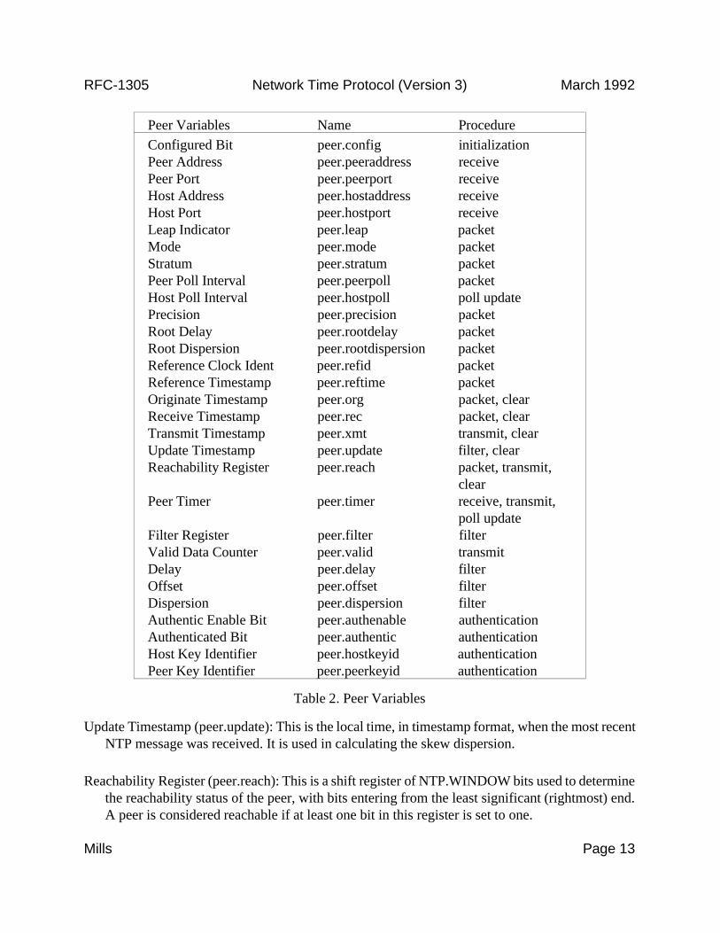


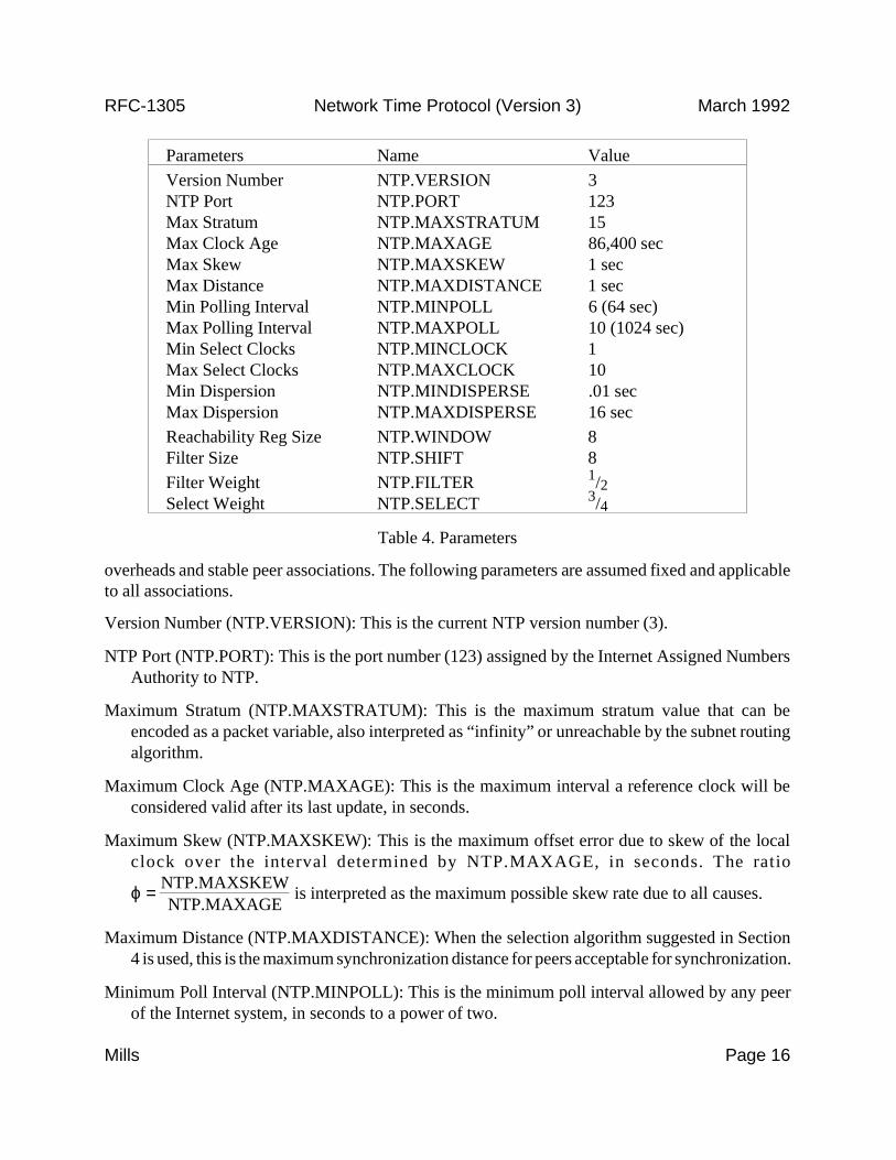
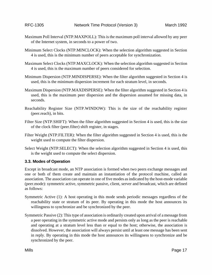


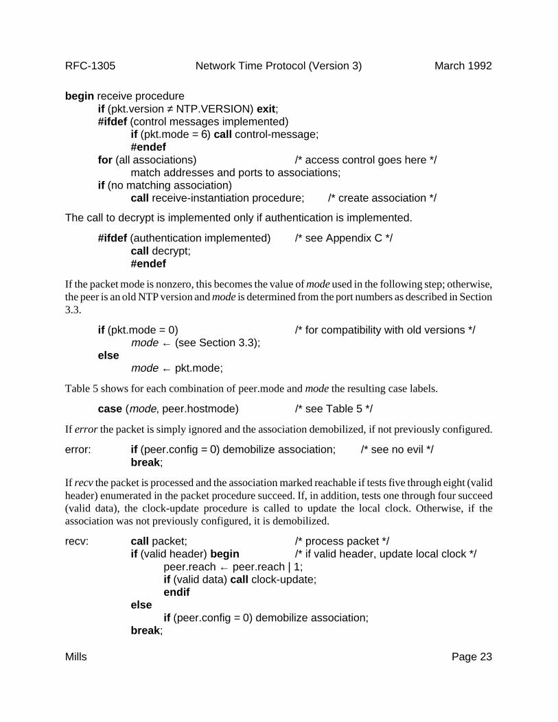
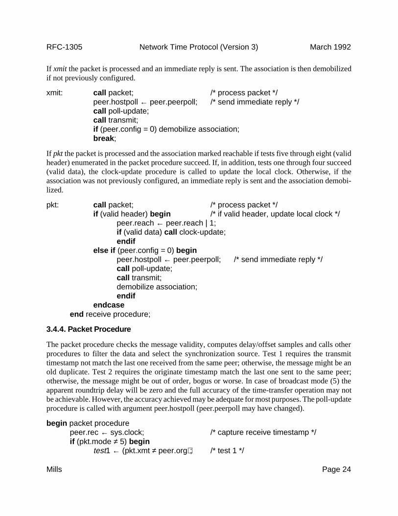

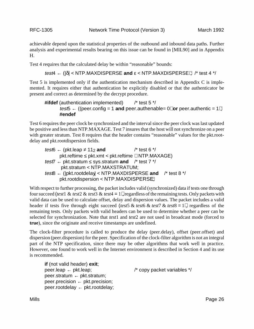


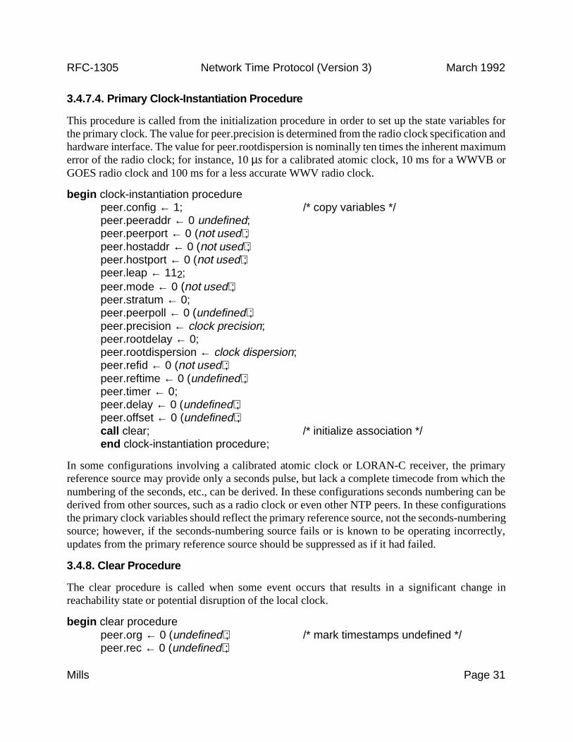


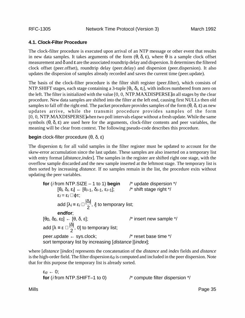


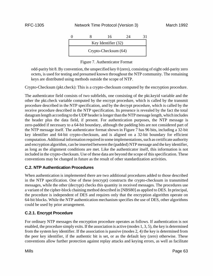
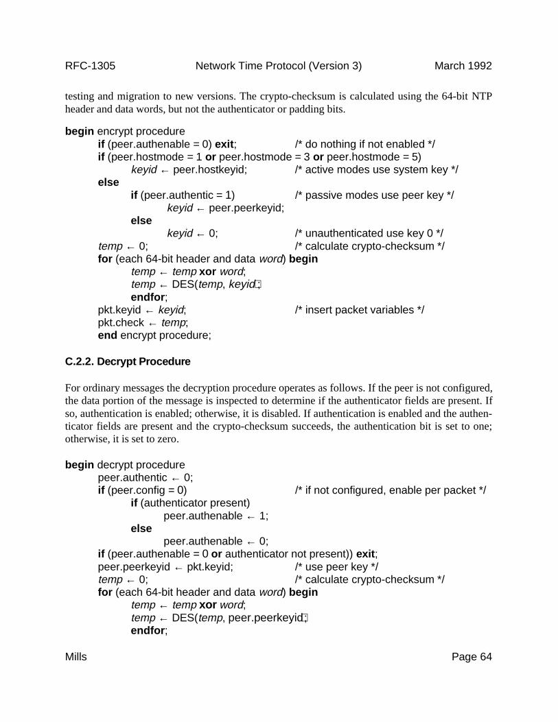


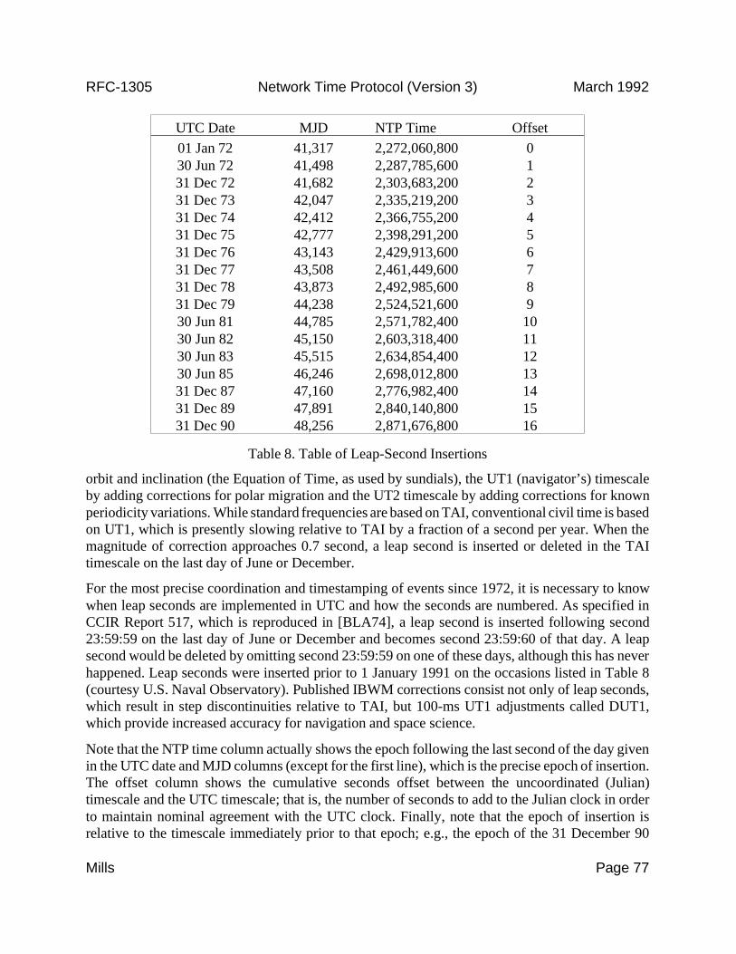


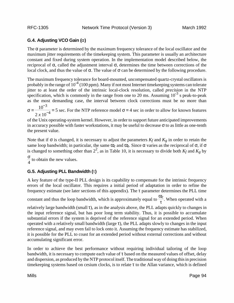


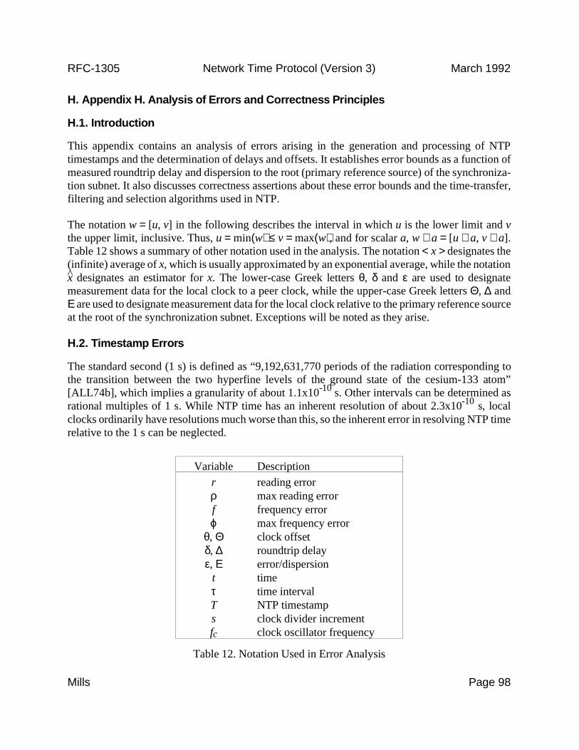


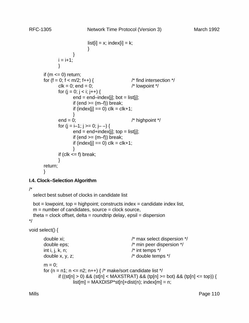


![Attacking the Network Time Protocol · NTP that are possible within the NTP protocol specifica-tion [47]. We consider both (1) on-path attacks, where the attacker occupies a privileged](https://static.documents.pub/doc/80x56/5f0417e67e708231d40c4958/attacking-the-network-time-protocol-ntp-that-are-possible-within-the-ntp-protocol.jpg)


![[MS-SNTP-Diff]: Network Time Protocol (NTP) Authentication ...download.microsoft.com/download/C/6/C/C6C3C6F1-E84A-44EF-82A9-49BD3AAD... · The Network Time Protocol (NTP) Authentication](https://static.documents.pub/doc/80x56/5d4f14b588c99322798b8f90/ms-sntp-diff-network-time-protocol-ntp-authentication-the-network-time.jpg)


