Network Video Recorder User Manual Models 4-Channel NVR with PoE 8-Channel NVR with PoE 16-Channel NVR with PoE 32-Channel NVR with PoE 64-Channel NVR with PoE Last Modified: 09/29/2016 Note: The Network Video Recorder User Manual will no longer be updated. For up to date NVR information, see our Knowledge Base. https://knowledgebaseclarecontrols.atlassian.net/wiki/display/CVIS/Network+Vide o+Recorder+%28NVR%29+User+Guide DOC ID: 371 • Rev 07
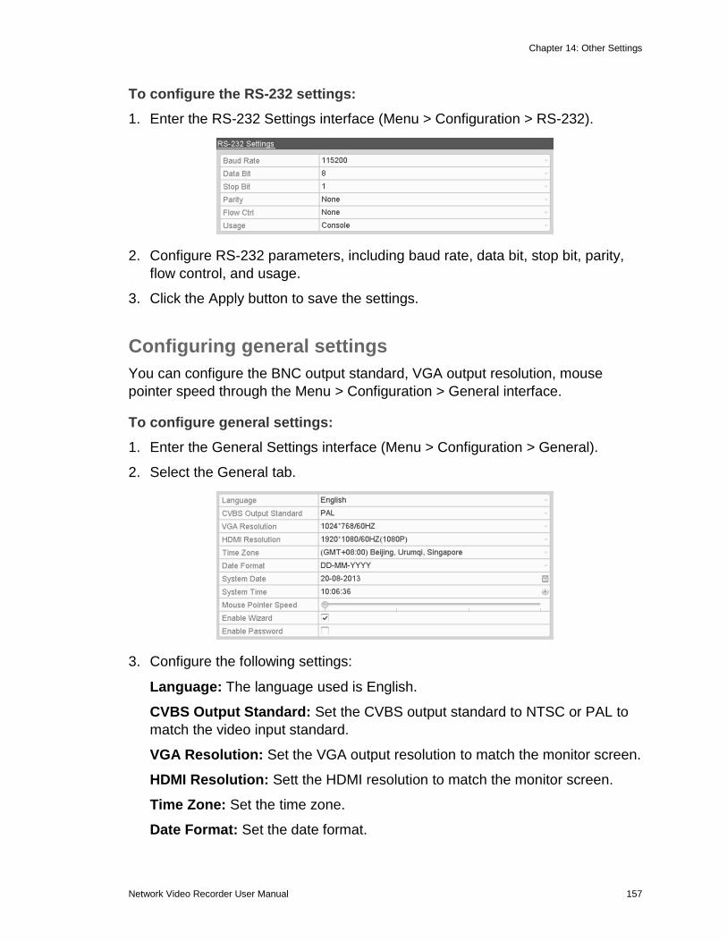
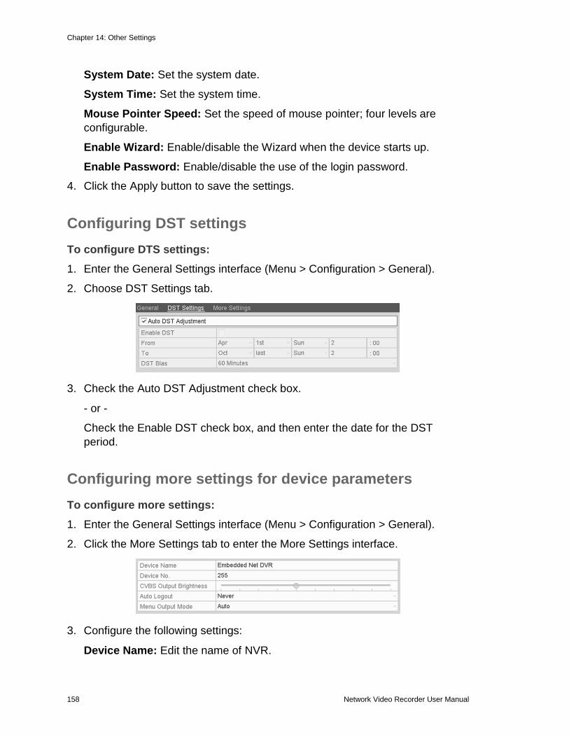
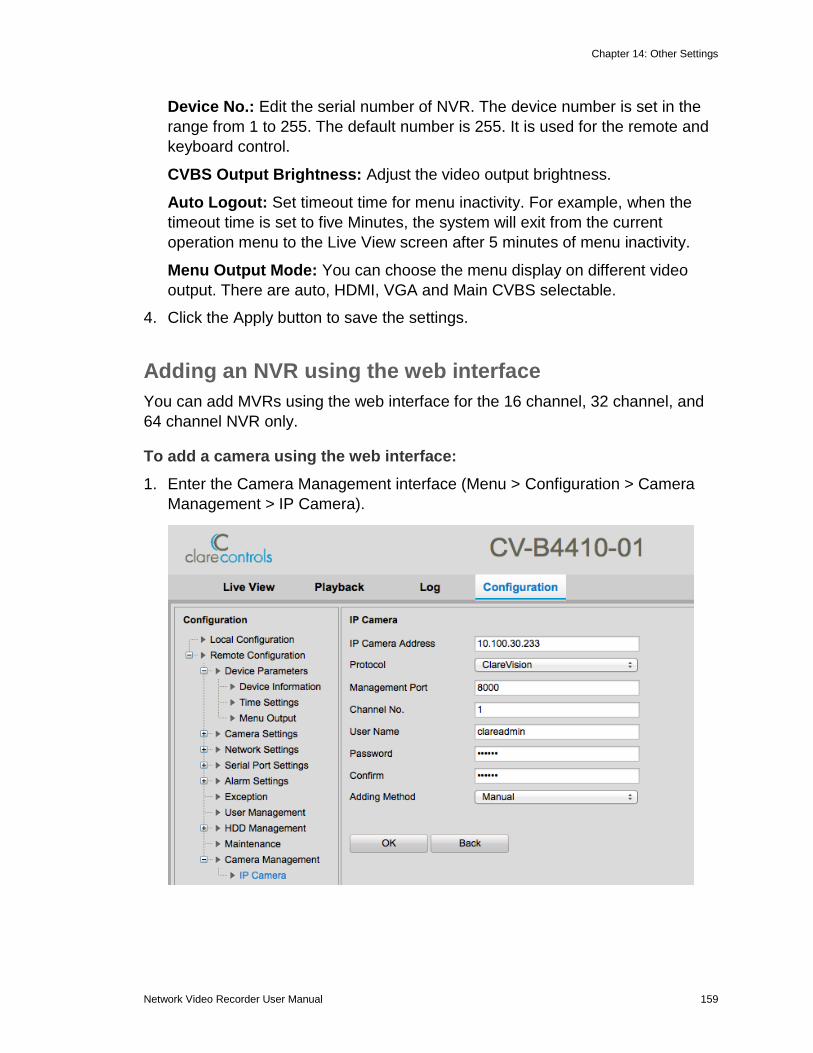
Transcript
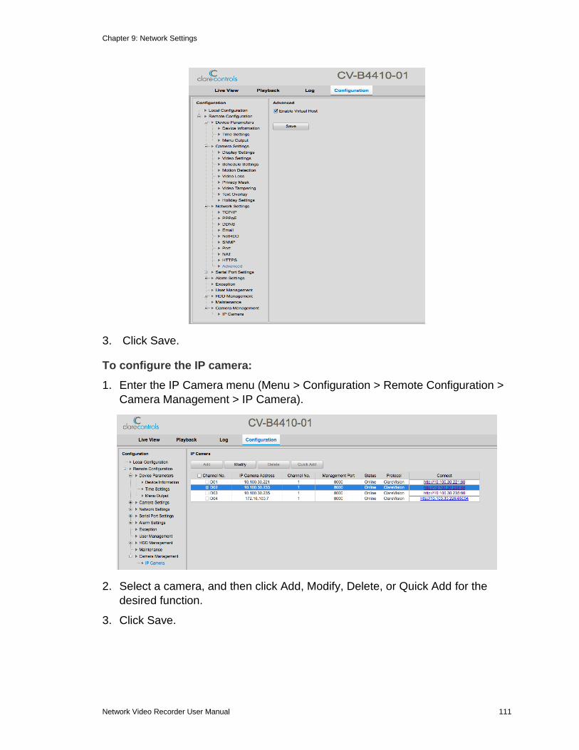
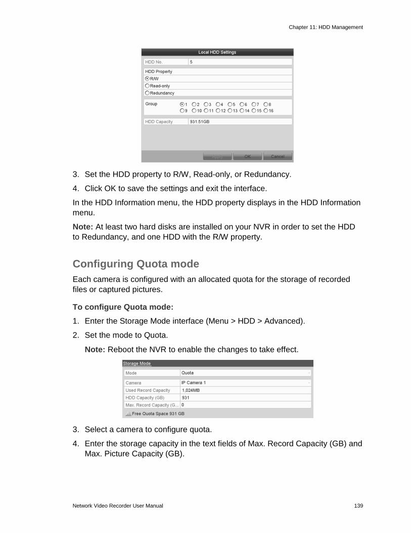
Network Video Recorder User Manual Models 4-Channel NVR with PoE 8-Channel NVR with PoE 16-Channel NVR with PoE 32-Channel NVR with PoE 64-Channel NVR with PoE
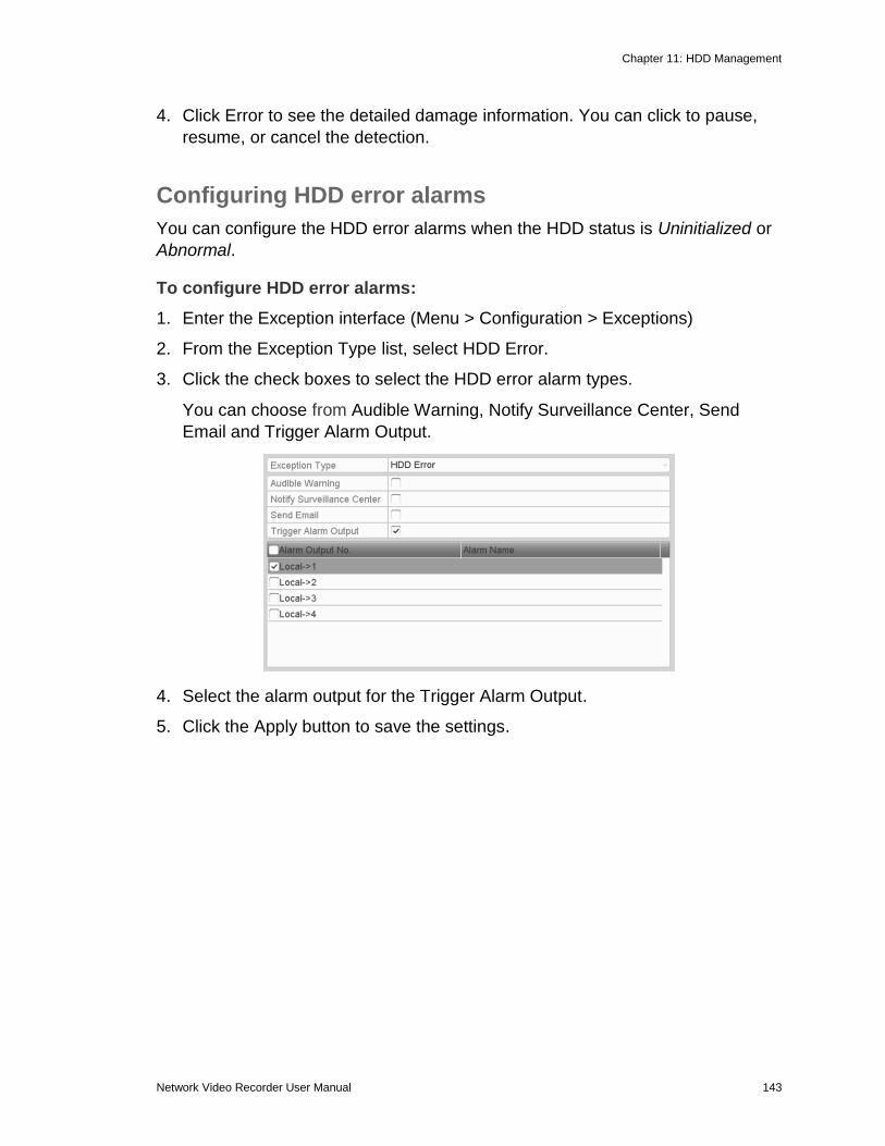
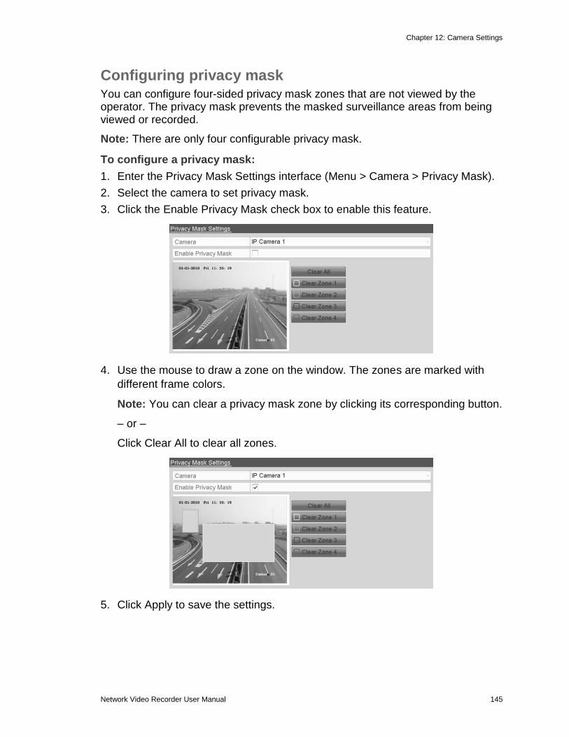
Last Modified: 09/29/2016
Note: The Network Video Recorder User Manual will no longer be updated. For
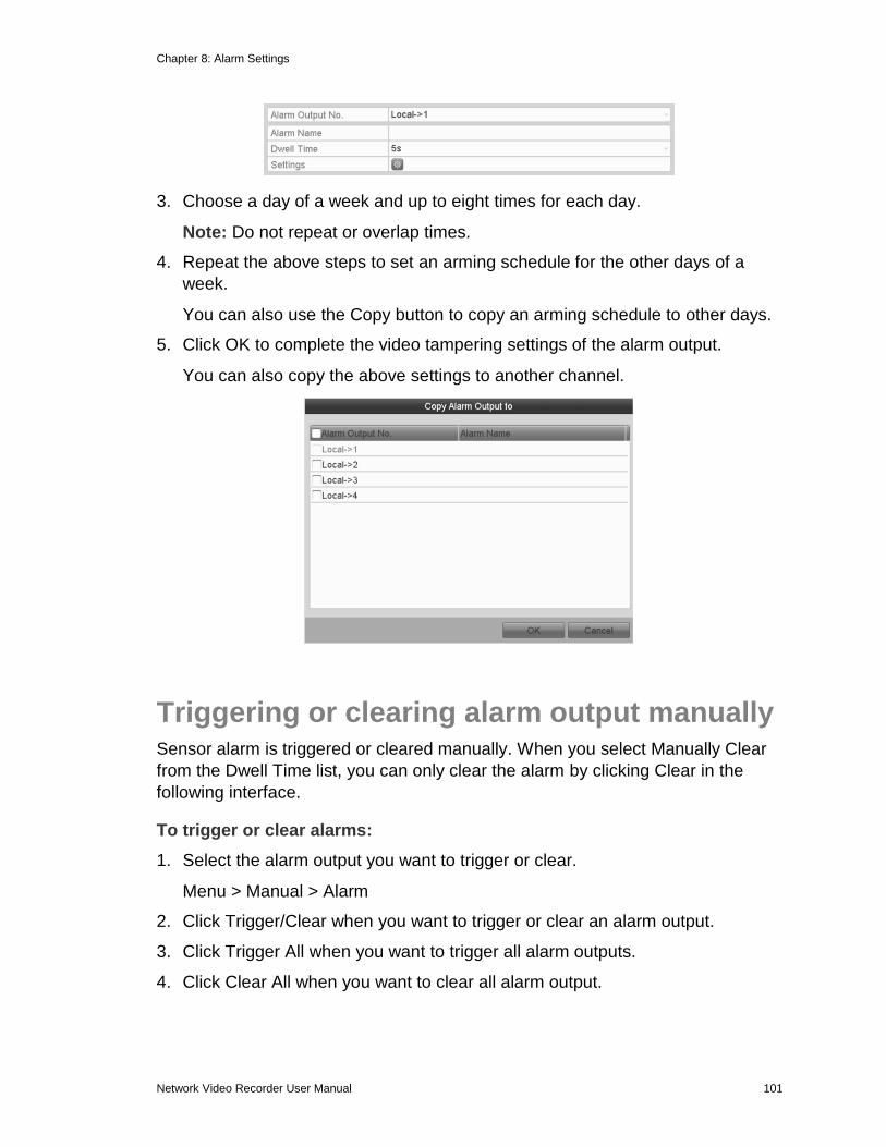
up to date NVR information, see our Knowledge Base.
This document may not be copied in whole or in part or otherwise
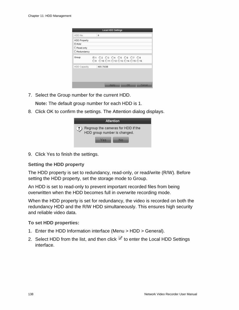
reproduced without prior written consent from Clare Controls, LLC.,
except where specifically permitted under US and international
copyright law.
Trademarks and
patents
The Clare Controls Network Video Recorder User Manual name and
logo are trademarks of Clare Controls, LLC.
Other trade names used in this document may be trademarks or
registered trademarks of the manufacturers or vendors of the
respective products.
Manufacturer Clare Controls, LLC.
7519 Pennsylvania Ave., Suite 104, Sarasota, FL 34243, USA
Contact information Clare Controls, LLC.
7519 Pennsylvania Ave, Suite 104
Sarasota, FL 34243
Support: 941.404.1072
Fax: 941.870.9646
http://support.clarecontrols.com
www.clarecontrols.com
Network Video Recorder User Manual i
Content
Important information ............................................................................ v
Limitation of liability .............................................................................. v Advisory messages .............................................................................. v Warranty information ............................................................................ v
IR remote control operations ................................................................ 6 Troubleshooting the remote control ........................................... 8
USB mouse operation .......................................................................... 9 The mouse operation ................................................................. 9
Chapter 2 Getting Started ................................................................................ 16 Starting up and shutting down the NVR .............................................. 16
Shutting down the NVR ........................................................... 17
Rebooting the NVR .................................................................. 18 Using the wizard for basic configuration ............................................. 19
Adding and connecting the IP cameras .............................................. 24 Adding the online IP cameras ............................................................. 24 Editing the connected IP cameras and configuring customized protocols ............................................................................................. 26
Configuring the customized protocols ................................................. 27 Editing IP cameras connected to the PoE interfaces ............... 29
Chapter 3 Introduction to Live View ............................................................... 30
Introduction to Live View .................................................................... 30 Operations in Live View mode ............................................................ 30
Front panel operation in Live View ........................................... 31 Using the mouse in Live View .................................................. 32
Using an auxiliary monitor ....................................................... 33 Quick Setting toolbar in Live View mode ................................. 34
Adjusting Live View settings ............................................................... 35 Setting cameras order ............................................................. 36
Configuring motion detection record and capture ............................... 50 Configuring alarm triggered record and capture ................................. 52
Manual record and continuous capture .............................................. 54 Configuring holiday record and capture ............................................. 55 Configuring redundant recording and capture .................................... 56
Configuring HDD group for recording and capture ............................. 57 Files protection ................................................................................... 58
Playing back record files .................................................................... 61 Playing back by channel .......................................................... 61 Playing back by time ................................................................ 63
Playing back by event search .................................................. 65
Playing back by tag ................................................................. 69
Playing back by system logs ................................................... 72 Playing back external file ......................................................... 73
Auxiliary functions of playback ........................................................... 74 Playing back frame by frame ................................................... 74 Digital zoom ............................................................................. 74
Reverse playback of multi-channel .......................................... 75 Picture playback ................................................................................. 75 Backing up recorded files ................................................................... 78 Backing up by normal video search ................................................... 78 Backing up by event search ............................................................... 84
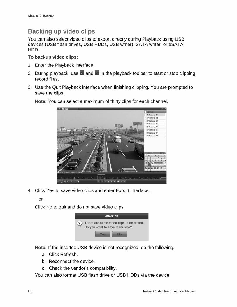
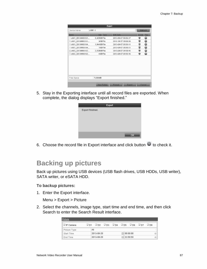
Backing up video clips ........................................................................ 86
Backing up pictures ............................................................................ 87 Managing backup devices .................................................................. 89
Automatically rebuilding the array .................................................... 125 Manually rebuilding array ................................................................. 126 Repairing a virtual disk ..................................................................... 127
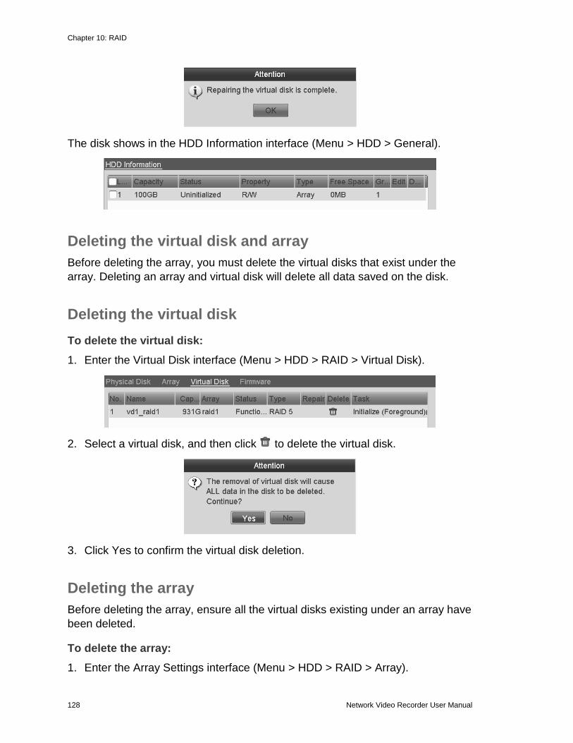
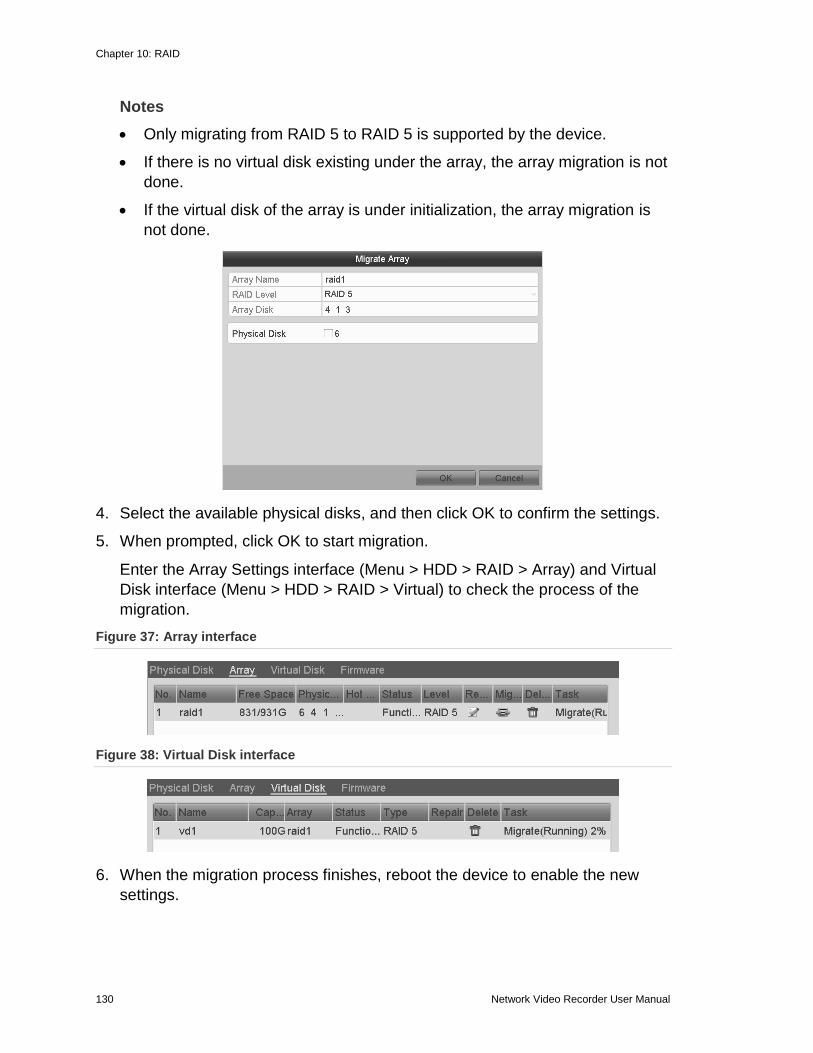
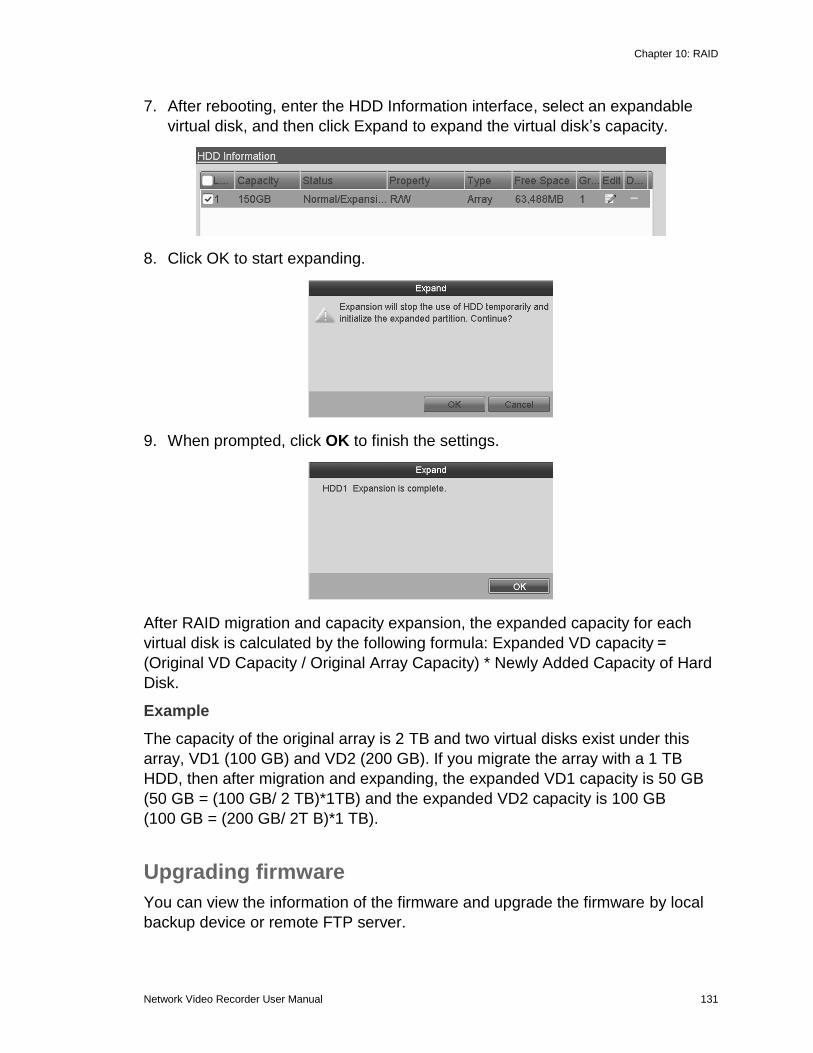
Deleting the virtual disk and array .................................................... 128 Deleting the virtual disk .................................................................... 128 Deleting the array ............................................................................. 128 Migrating and extending ................................................................... 129 Upgrading firmware .......................................................................... 131 Initializing HDDs ............................................................................... 133
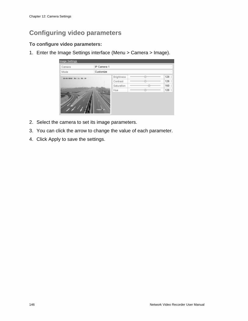
Configuring video parameters .......................................................... 146
Chapter 13 NVR Management and Maintenance ......................................... 147
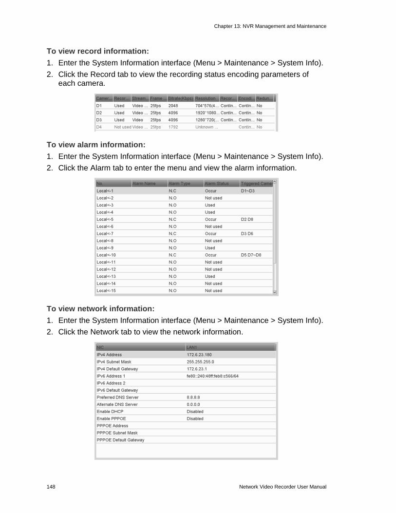
Viewing system information .............................................................. 147 Searching and export log files .......................................................... 149
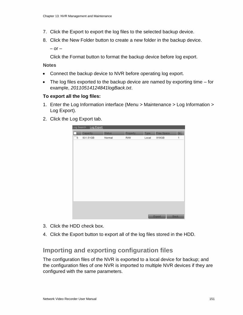
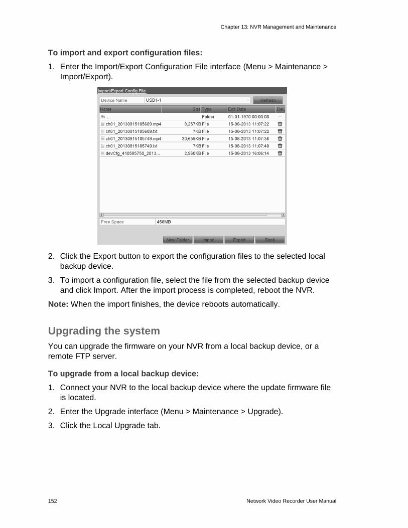
Importing and exporting configuration files ....................................... 151 Upgrading the system ...................................................................... 152 Restoring default settings ................................................................. 154
Chapter 14 Other Settings ............................................................................. 155 Understanding camera capacity in an NVR...................................... 155
Streaming video types ........................................................... 155 Adjusting settings .................................................................. 156
Configuring RS-232 serial ports ....................................................... 156
Configuring general settings ............................................................. 157 Configuring DST settings ................................................................. 158
Configuring more settings for device parameters ............................. 158 Adding an NVR using the web interface ........................................... 159
Managing user accounts .................................................................. 160 Adding a user ........................................................................ 160 Deleting a user ...................................................................... 163
Editing a user ........................................................................ 163
Appendix A Troubleshooting ........................................................................ 165
To the maximum extent permitted by applicable law, in no event will Clare
Controls, LLC. be liable for any lost profits or business opportunities, loss of use,
business interruption, loss of data, or any other indirect, special, incidental, or
consequential damages under any theory of liability, whether based in contract,
tort, negligence, product liability, or otherwise. Because some jurisdictions do not
allow the exclusion or limitation of liability for consequential or incidental
damages the preceding limitation may not apply to you. In any event the total
liability of Clare Controls, LLC. shall not exceed the purchase price of the
product. The foregoing limitation will apply to the maximum extent permitted by
applicable law, regardless of whether Clare Controls, LLC. has been advised of
the possibility of such damages and regardless of whether any remedy fails of its
essential purpose.
Installation in accordance with this manual, applicable codes, and the instructions
of the authority having jurisdiction is mandatory.
While every precaution has been taken during the preparation of this manual to
ensure the accuracy of its contents, Clare Controls, LLC. assumes no
responsibility for errors or omissions.
Advisory messages
Advisory messages alert you to conditions or practices that can cause unwanted results. The advisory message used in this document is shown and described below. Note: Note messages advise you of the possible loss of time or effort. They describe how to avoid the loss. Notes are also used to point out important information that you should read.
Warranty information
Clare Controls offers a three (3) year limited warranty on original Clare Controls components, from the date of shipment from Clare Controls. To view complete limited warranty details, including limitations and exclusions, www.clarecontrols.com/warranty.
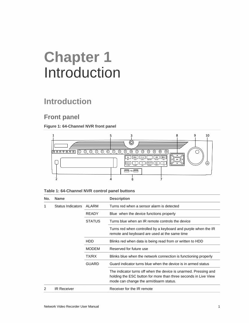
1 Status Indicators ALARM Turns red when a sensor alarm is detected
READY Blue when the device functions properly
STATUS Turns blue when an IR remote controls the device
Turns red when controlled by a keyboard and purple when the IR
remote and keyboard are used at the same time
HDD Blinks red when data is being read from or written to HDD
MODEM Reserved for future use
TX/RX Blinks blue when the network connection is functioning properly
GUARD Guard indicator turns blue when the device is in armed status
The indicator turns off when the device is unarmed. Pressing and
holding the ESC button for more than three seconds in Live View
mode can change the arm/disarm status.
2 IR Receiver Receiver for the IR remote
Chapter 1: Introduction
2 Network Video Recorder User Manual
3 Front Panel Lock Lock or unlock the panel with the key
4 DVD-R/W Slot for DVD-R/W
5 Alphanumeric Buttons Switch to the corresponding channel in Live view or PTZ Control
mode
Switch between different channels in Playback mode
The button is blue when the corresponding channel is recording;
red when the channel is in network transmission status; and pink
when the channel is recording and transmitting
6 USB Interfaces Universal Serial Bus (USB) ports for additional devices such as
USB mouse and USB Hard Disk Drive (HDD)
7 Composite Keys ESC Return to the previous menu
Press for arming or disarming the device in Live View mode
REC/SHOT Enter the Manual Record setting menu
In the PTZ control settings, press REC/SHOT and then press a
Numeric button to call a PTZ preset
Turn audio on and off in Playback mod
PLAY/AUTO Use to enter Playback mode
Use to auto-scan in the PTZ Control menu
ZOOM+ Zoom in the PTZ camera in the PTZ Control setting
A/FOCUS+ Adjust focus in the PTZ Control menu
Use to switch between input methods (upper and lowercase
alphabet, symbols and numeric input)
EDIT/IRIS+ Edit text fields. When editing text fields, it functions as a
Backspace button
On check box fields, pressing the button will check the box
In PTZ Control mode, the button adjusts the iris of the camera
Use in Playback mode to generate video clips for backup
Enter or exit the folder of USB device and eSATA HDD
MAIN/SPOT/
ZOOM
Switch between main and spot output
Use in PTZ Control mode to zoom out of the image
Chapter 1: Introduction
Network Video Recorder User Manual 3
F1/LIGHT Select all items on the list when used in a list field.
In PTZ Control mode, it will turn on/off PTZ light (if applicable).
Use in Playback mode to switch between play and reverse play.
F2/AUX Cycle through tab pages.
In synchronous playback mode, it is used to switch between
channels.
MENU/WIPER Press the button to return to the Main menu (after successful
login).
Press and hold the button for 5 seconds will turn off audible key
beep.
In PTZ Control mode, the MENU/WIPER button will start wiper (if applicable).
In Playback mode, it is used to show/hide the control interface.
PREV/FOCUS Switch between single screen and multi-screen mode.
In PTZ Control mode, it is used to adjust the focus in conjunction with the A/FOCUS+ button.
PTZ/IRIS- Enter the PTZ Control mode.
In the PTZ Control mode, it is used to adjust the iris of the PTZ camera.
8 Control Buttons DIRECTION The DIRECTION buttons are used to navigate between different fields and items in menus.
In the Playback mode, use the Up and Down button to speed up and slow down recorded video. The Left and Right button select the next and previous record files.
In Live View mode, use these buttons to cycle through channels.
In PTZ control mode, control the movement of the PTZ camera.
ENTER The ENTER button is used to confirm selection in any of the menu modes.
Use to check the check box fields.
In Playback mode, it is used to play or pause the video.
In single-frame Playback mode, pressing the button will advance the video by a single frame.
In Auto-switch mode, use to stop /start auto switch.
9 JOG SHUTTLE Control Move the active selection in a menu. It will move the selection up and down.
In Live View mode, use to cycle through different channels.
In the Playback mode: For 64-Channel NVRs, the ring is used
to jump 30s forward/backward in video files.
In PTZ control mode, it control the movement of the PTZ camera.
10 POWER ON/OFF Power on/off switch.
Chapter 1: Introduction
4 Network Video Recorder User Manual
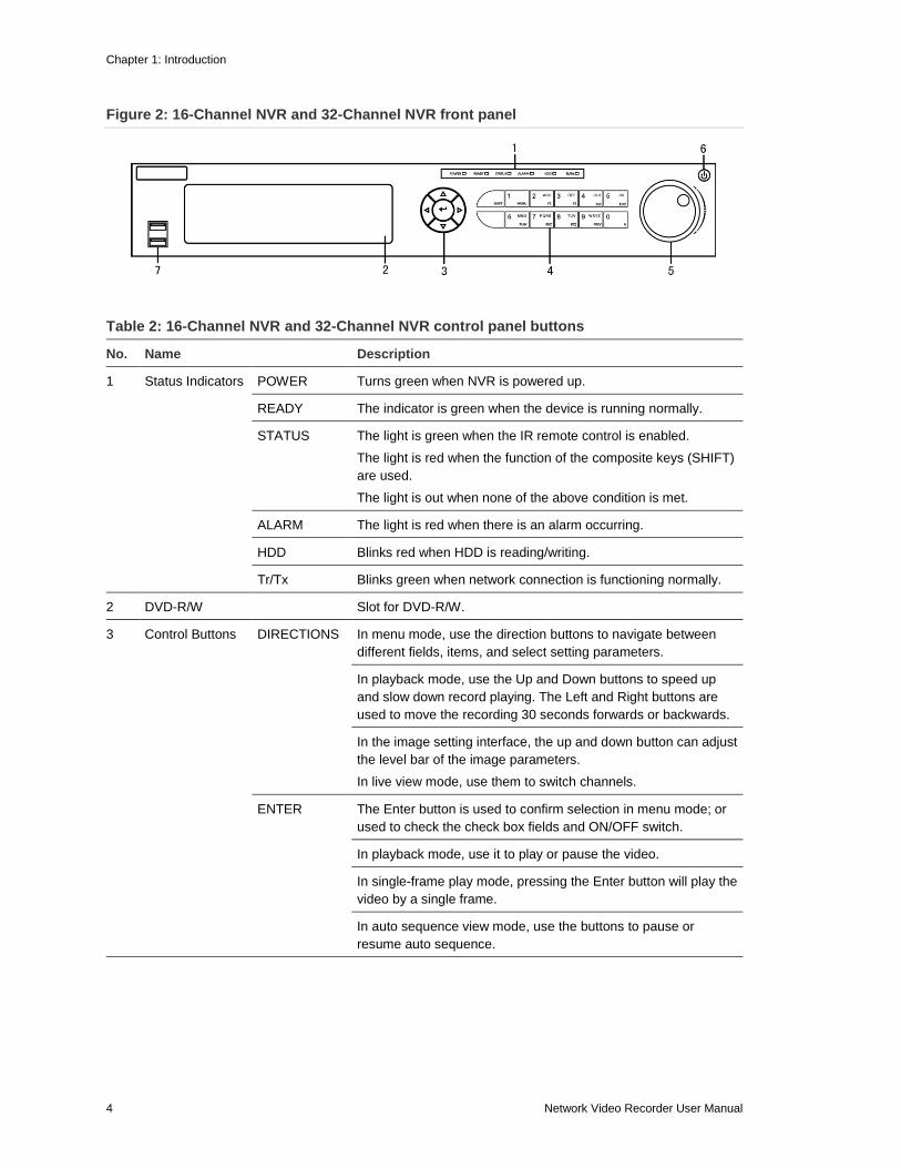
Figure 2: 16-Channel NVR and 32-Channel NVR front panel
Table 2: 16-Channel NVR and 32-Channel NVR control panel buttons
No. Name Description
1 Status Indicators POWER Turns green when NVR is powered up.
READY The indicator is green when the device is running normally.
STATUS The light is green when the IR remote control is enabled.
The light is red when the function of the composite keys (SHIFT)
are used.
The light is out when none of the above condition is met.
ALARM The light is red when there is an alarm occurring.
HDD Blinks red when HDD is reading/writing.
Tr/Tx Blinks green when network connection is functioning normally.
2 DVD-R/W Slot for DVD-R/W.
3 Control Buttons DIRECTIONS In menu mode, use the direction buttons to navigate between
different fields, items, and select setting parameters.
In playback mode, use the Up and Down buttons to speed up
and slow down record playing. The Left and Right buttons are
used to move the recording 30 seconds forwards or backwards.
In the image setting interface, the up and down button can adjust
the level bar of the image parameters.
In live view mode, use them to switch channels.
ENTER The Enter button is used to confirm selection in menu mode; or
used to check the check box fields and ON/OFF switch.
In playback mode, use it to play or pause the video.
In single-frame play mode, pressing the Enter button will play the
video by a single frame.
In auto sequence view mode, use the buttons to pause or
resume auto sequence.
Chapter 1: Introduction
Network Video Recorder User Manual 5
4 Composite Keys SHIFT Switch between the numeric or letter input and functions of the
composite keys. (Input letter or numbers when the light is out;
Realize functions when the light is red.)
1/MENU Access the main menu interface.
2/ABC/F1 The F1 button, when used in a list field, selects all items in the
list.
In PTZ Control mode, it will turn on/off PTZ light and when the
image is zoomed in, the key is used to zoom out.
3/DEF/F2 The F2 button is used to change the tab pages.
In PTZ control mode, it zooms in the image.
4/FHI/ESC Exit and back to the previous menu.
5/JKL/EDIT Delete characters before cursor.
Check the check box and select the ON/OFF switch.
Start/stop record clipping in playback.
6/MNO/PLAY Playback, for direct access to playback interface.
7/PQRS/REC Open the manual record interface.
8/TUV/PTZ Access PTZ control interface.
9/WXYZ/PREV Multi-channel display in live view.
0/A Shift the input methods in the editing text field. (Upper and
lowercase, alphabet, symbols or numeric input).
Double-press the button to switch the main and auxiliary output.
5 JOG SHUTTLE Control Move the active selection in a menu. It will move the selection up
and down.
In Live View mode, use it to cycle through different channels.
In the Playback mode, use it to jump 30s forward/backward in
video files.
In PTZ control mode, it controls the movement of the PTZ
camera.
6 POWER ON/OFF Power on/off switch.
7 USB Interfaces Universal Serial Bus (USB) ports for additional devices such as
USB mouse and USB Hard Disk Drive (HDD).
Chapter 1: Introduction
6 Network Video Recorder User Manual
Figure 3: 4-Channel and 8-Channel NVR front panel
Table 3: 4-Channel and 8-Channel NVR control panel buttons
No. Name Description
1 Power The POWER LED turns green when NVR is powered up.
2 Status READY: The LED is green when the device is running normally.
STATUS:
1) The light is green when the IR remote control is enabled.
2) The light is red when the function of the composite keys (SHIFT) is used.
3) The light is out when none of the above condition is met.
ALARM: The light is red when there is an alarm occurring.
HDD: The LED flashes red when HDD is reading/writing.
3 Tx/Rx TX/RX LED flashes green when network connection is functioning normally.
4 USB USB connector.
IR remote control operations
The included IR remote controls the NVR, shown below. The keys on the remote
control closely resemble the ones on the front panel.
Note: Install batteries (2 × AAA) before operation.
1 2 3 4
Chapter 1: Introduction
Network Video Recorder User Manual 7
Figure 4: Remote control
Table 4: Remote control buttons
No. Name Description
1 POWER Power on/off the device.
2 DEV Enables/Disables Remote Control.
3 Alphanumeric buttons Same as Alphanumeric buttons on front panel.
4 EDIT button Same as EDIT/IRIS+ button on front panel.
5 A button Same as A/FOCUS+ button on front panel.
6 REC button Same as REC/SHOT button on front panel.
7 PLAY button Same as the PLAY/AUTO button on front panel.
8 INFO button Reserved.
9 VOIP/MON button Same as the MAIN/SPOT/ZOOM- button on front panel.
10 MENU button Same as the MENU/WIPER button on front panel.
11 PREV button Same as the PREV/FOCUS- button on front panel.
12 DIRECTION/ENTER buttons Same as the DIRECTION/ENTER buttons on front panel.
13 PTZ button Same as the PTZ/IRIS- button on front panel.
14 ESC button Same as the ESC button on front panel.
15 RESERVED Reserved for future use.
16 F1 button Same as the F1/LIGHT button on front panel.
17 PTZ Control buttons Buttons to adjust the iris, focus and zoom of a PTZ camera.
18 F2 button Same as the F2/AUX button on front panel.
Chapter 1: Introduction
8 Network Video Recorder User Manual
Troubleshooting the remote control
Note: Make sure you have installed the batteries properly in the remote control.
Aim the remote control at the IR receiver in the front panel.
If you press a button and do not receive a response, follow the procedures below
to troubleshoot.
To troubleshoot the remote control:
1. Go to Menu > Settings > General > More Settings using the front control
panel or the mouse.
2. Check and remember the NVR ID. The default ID number is 255. This ID
number is valid for all the IR remote controls.
3. Press the DEV button on the remote control.
4. Enter the NVR ID number from step 2.
5. Press ENTER on the remote.
If the Status indicator on the front panel turns blue, the remote control is
operating properly. If the Status indicator does not turn blue and there is no
response from the remote, check the following:
Batteries are installed correctly and the polarities of the batteries are not
reversed.
Batteries are fresh and charged.
IR receiver is not obstructed.
If the remote still is not functioning properly, change remotes and try again, or
contact your dealer.
Chapter 1: Introduction
Network Video Recorder User Manual 9
USB mouse operation
A regular three-button (Left/Right/Scroll-wheel) USB mouse works with the NVR.
To use a USB mouse:
1. Plug USB mouse into one of the USB interfaces on the front panel of the
NVR.
2. The mouse is detected automatically. If in the rare case the mouse is not
detected, it is possible that the two devices are not compatible. Refer to the
recommended device list from your provider.
The mouse operation
Table 5: Mouse control
Name Action Description
Left-click Single-click Live view: Select channel and show the quick set menu.
Menu: Select and enter.
Double-click Live view: Switch between single-screen and multi-screen.
Click and drag PTZ control: Pan, tilt and zoom.
Video tampering, privacy mask and motion detection:
Select target area.
Digital zoom-in: Drag and select target area.
Live view: Drag channel/time bar.
Right-click Single-click Live view: Show menu.
Menu: Exit current menu to previous menu.
Wheel- scroll Scrolling up Live view: Previous screen.
Menu: Previous item.
Scrolling down Live view: Next screen.
Menu: Next item.
Chapter 1: Introduction
10 Network Video Recorder User Manual
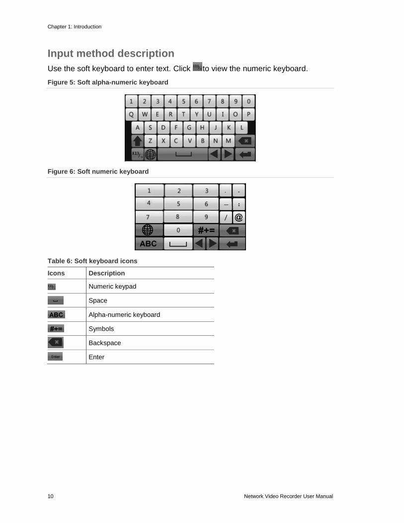
Input method description
Use the soft keyboard to enter text. Click to view the numeric keyboard.
Figure 5: Soft alpha-numeric keyboard
Figure 6: Soft numeric keyboard
Table 6: Soft keyboard icons
Icons Description
Numeric keypad
Space
Alpha-numeric keyboard
Symbols
Backspace
Enter
Chapter 1: Introduction
Network Video Recorder User Manual 11
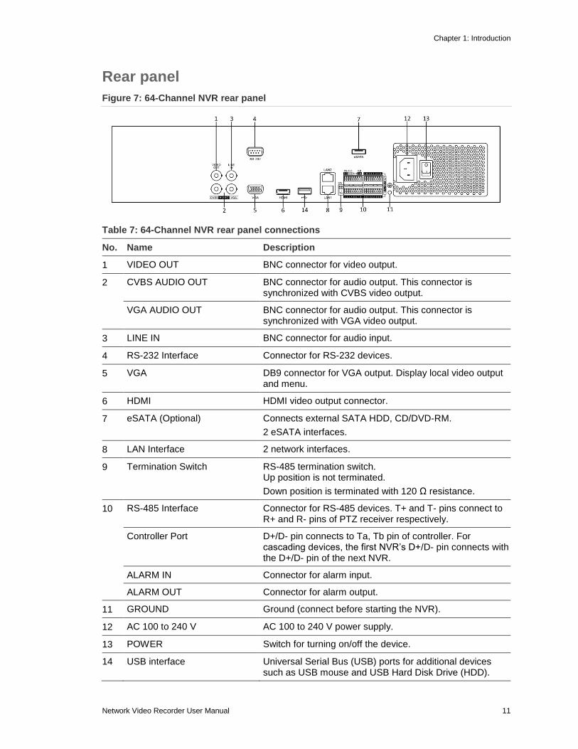
Rear panel
Figure 7: 64-Channel NVR rear panel
Table 7: 64-Channel NVR rear panel connections
No. Name Description
1 VIDEO OUT BNC connector for video output.
2 CVBS AUDIO OUT BNC connector for audio output. This connector is synchronized with CVBS video output.
VGA AUDIO OUT BNC connector for audio output. This connector is synchronized with VGA video output.
3 LINE IN BNC connector for audio input.
4 RS-232 Interface Connector for RS-232 devices.
5 VGA DB9 connector for VGA output. Display local video output and menu.
6 HDMI HDMI video output connector.
7 eSATA (Optional) Connects external SATA HDD, CD/DVD-RM.
2 eSATA interfaces.
8 LAN Interface 2 network interfaces.
9 Termination Switch RS-485 termination switch. Up position is not terminated.
Down position is terminated with 120 Ω resistance.
10 RS-485 Interface Connector for RS-485 devices. T+ and T- pins connect to R+ and R- pins of PTZ receiver respectively.
Controller Port D+/D- pin connects to Ta, Tb pin of controller. For cascading devices, the first NVR’s D+/D- pin connects with the D+/D- pin of the next NVR.
ALARM IN Connector for alarm input.
ALARM OUT Connector for alarm output.
11 GROUND Ground (connect before starting the NVR).
12 AC 100 to 240 V AC 100 to 240 V power supply.
13 POWER Switch for turning on/off the device.
14 USB interface Universal Serial Bus (USB) ports for additional devices such as USB mouse and USB Hard Disk Drive (HDD).
Chapter 1: Introduction
12 Network Video Recorder User Manual
Figure 8: 16-Channel and 32-Channel rear panel connections
Table 8: 16-Channel and 32 Channel rear panel connections
No. Item Description
1 eSATA (Optional) Connects an external hard drive.
2 RS-232 Interface Connector for the RS-232 devices.
3 VIDEO OUT BNC connector for the video output.
4 VGA VGA output 15 pin connector. Displays the local video output and the menu.
5 LINE IN BNC connector for the audio input.
6 Termination Switch RS-485 termination switch. The up position is not terminated. The down position is terminated with 120 Ω resistance.
7 RS-485 Interface Connector for the RS-485 devices. The T+ and T- pins connect to the R+ and R- pins of the PTZ receiver respectively.
Controller Port The D+, and the D- pin connects to the Ta, and the Tb pin of the controller. For cascading devices, the first NVR’s D+, D- pin should be connected with the D+, D- pin of the next NVR.
ALARM IN Connector for alarm input.
ALARM OUT Connector for alarm output.
8 Network Interfaces with PoE function
Network interfaces for the cameras and to provide power over Ethernet (PoE).
9 CVBS AUDIO OUT BNC connector for the audio output. This connector is synchronized with the CVBS video output.
VGA AUDIO OUT BNC connector for the audio output. This connector is synchronized with the VGA video output.
10 HDMI HDMI video output.
11 USB interface Universal Serial Bus (USB) ports for additional devices such as USB mouse and USB Hard Disk Drive (HDD).
12 LAN Interface One network interface provided.
13 GROUND Ground (must be connected when the NVR starts.)
14 AC 100 V to 240 V AC 100 V to 240 V power input.
15 POWER Switch for turning the device on/off.
1 2 3 4 5
9 10 11 12 13
6 7 8
161514
eSATA
RS-485 KB ALARM INSWON
ALARM OUT
(1) (2) (3) (4) (5) (6) (7)
(8) (9) (10) (11) (12) (13) (14) (15)
Chapter 1: Introduction
Network Video Recorder User Manual 13
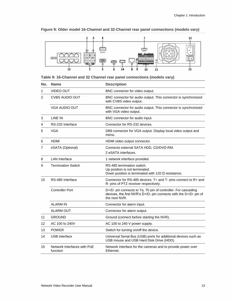
Figure 9: Older model 16-Channel and 32-Channel rear panel connections (models vary)
2 CVBS AUDIO OUT BNC connector for audio output. This connector is synchronized with CVBS video output.
VGA AUDIO OUT BNC connector for audio output. This connector is synchronized with VGA video output.
3 LINE IN BNC connector for audio input.
4 RS-232 Interface Connector for RS-232 devices.
5 VGA DB9 connector for VGA output. Display local video output and menu.
6 HDMI HDMI video output connector.
7 eSATA (Optional) Connects external SATA HDD, CD/DVD-RM.
2 eSATA interfaces.
8 LAN Interface 1 network interface provided.
9 Termination Switch RS-485 termination switch. Up position is not terminated. Down position is terminated with 120 Ω resistance.
10 RS-485 Interface Connector for RS-485 devices. T+ and T- pins connect to R+ and R- pins of PTZ receiver respectively.
Controller Port D+/D- pin connects to Ta, Tb pin of controller. For cascading devices, the first NVR’s D+/D- pin connects with the D+/D- pin of the next NVR.
ALARM IN Connector for alarm input.
ALARM OUT Connector for alarm output.
11 GROUND Ground (connect before starting the NVR).
12 AC 100 to 240V AC 100 to 240 V power supply.
13 POWER Switch for turning on/off the device.
14 USB interface Universal Serial Bus (USB) ports for additional devices such as USB mouse and USB Hard Disk Drive (HDD).
15 Network Interfaces with PoE function
Network interface for the cameras and to provide power over Ethernet.
Chapter 1: Introduction
14 Network Video Recorder User Manual
Figure 10: 8-Channel rear panel
Table 10: 8-Channel rear panel connections
No. Item Description
1 Network Interfaces with PoE function
Network interfaces for the cameras and provides power over Ethernet.
2 USB Connects USB disks and devices.
3 HDMI HDMI video output connector.
4 VGA DB9 connector for VGA output. Display local video output and menu.
5 AUDIO IN BNC connector for audio input. (Also for two-way audio.)
AUDIO OUT BNC connector for audio output.
6 LAN Interface 1 network interface.
7 RS-485 Interface Connector for RS-485 devices. T+ and T- pins connect to R+ and R- pins of PTZ receiver respectively.
8 Ground Ground (needs to be connected before the NVR starts up).
9 Power Supply 12 VDC power supply.
10 Power Switch Switch for turning on/off the device.
11 Fan Removes heat from the device.
(1) (2) (3) (4) (5) (6) (7) (8) (9) (10) (11)
Chapter 1: Introduction
Network Video Recorder User Manual 15
Figure 11: 4-Channel rear panel
Table 11: 4-Channel
No. Name Description
1 Network Interfaces with PoE function
Network interfaces for the cameras and to provide power over Ethernet.
2 USB Connects USB disks and devices.
3 HDMI HDMI video output connector.
4 Alarm Controls Interface Connector for alarm inputs and outputs.
5 VGA DB9 connector for VGA output. Display local video output and menu.
6 AUDIO IN BNC connector for audio input (also for two-way audio).
AUDIO OUT BNC connector for audio output.
7 LAN Interface 1 network interface.
8 RS-485 Interface Connector for RS-485 devices. T+ and T- pins connect to R+ and R- pins of PTZ receiver respectively.
9 Ground Ground (connect before starting the NVR).
10 Power Supply 12 VDC power supply.
11 Power Switch Switch for turning on/off the device.
12 Fan Removes heat from and cools the device.
16 Network Video Recorder User Manual
Chapter 2 Getting Started
Starting up and shutting down the NVR Proper startup and shutdown is crucial to expanding the life of the NVR. Before
you start, check that the voltage of the extra power supply matches the NVR’s
requirement, and that the ground connection is working properly.
To start the NVR:
1. Check that the power supply is plugged into an electrical outlet. We
recommend that you use an Uninterruptible Power Supply (UPS) with the
device. The Power indicator LED on the front panel is red, indicating the
device is getting power.
2. Press the power button on the front panel. The power indicator LED turns
blue, indicating start up.
3. After startup, the Power indicator LED will remain blue. A splash screen with
the status of the HDD appears on the monitor. Click the Live View screen to
view the Quick menu. The Quick menu, a row of icons at the bottom of the
screen, shows the HDD status. ‘X’ means that the HDD is not installed or is
not detected.
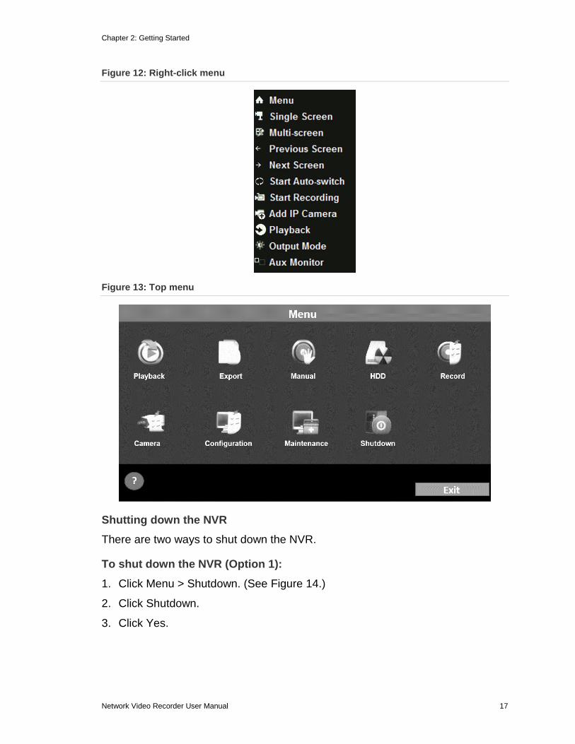
4. On the Live View screen, right click for the Right-click menu to appear, see
Figure 12 below. Click Menu, on the top of the Right-click menu to display the
Top menu, see Figure 13 below. From the Top menu, configure the advanced
settings or shutdown the NVR.
Chapter 2: Getting Started
Network Video Recorder User Manual 17
Figure 12: Right-click menu
Figure 13: Top menu
Shutting down the NVR
There are two ways to shut down the NVR.
To shut down the NVR (Option 1):
1. Click Menu > Shutdown. (See Figure 14.)
2. Click Shutdown.
3. Click Yes.
Chapter 2: Getting Started
18 Network Video Recorder User Manual
Figure 14: Shutdown menu
To shut down the NVR from the front panel (Option 2):
1. Press and hold the power button on the front panel for three seconds.
2. Enter the administrator’s username and password in the dialog box for
authentication.
3. Click Yes.
Note: Do not press the power button again when the system is shutting down.
Rebooting the NVR
Reboot the NVR in the Shutdown menu.
To reboot the NVR from the Shutdown menu:
1. Click Menu > Shutdown.
2. Click Reboot to reboot the NVR.
Chapter 2: Getting Started
Network Video Recorder User Manual 19
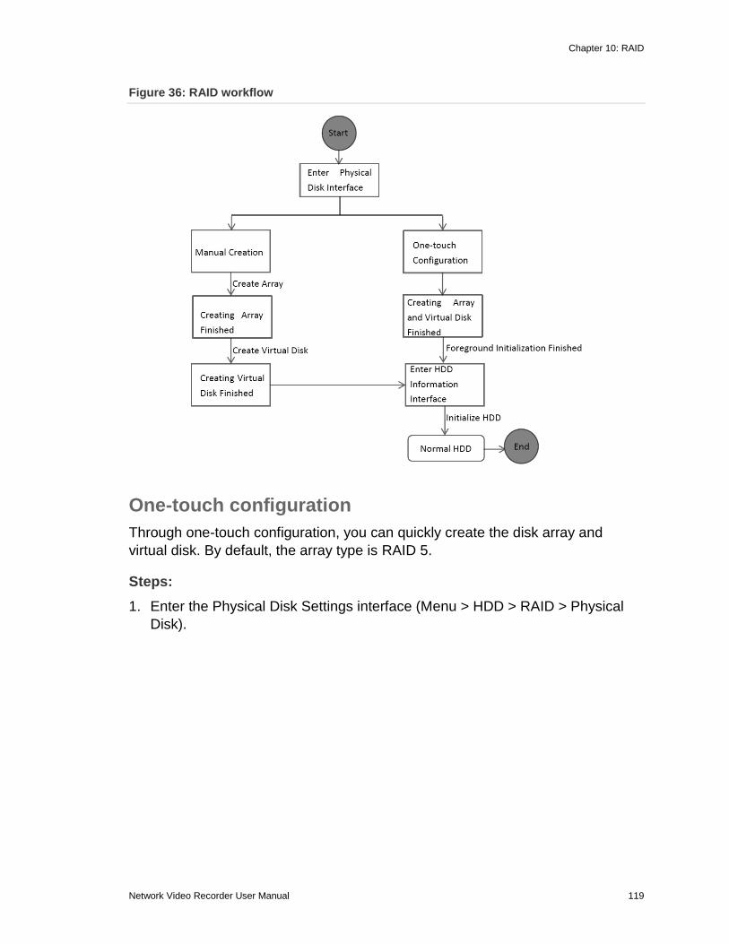
Using the wizard for basic configuration
By default, the Wizard starts once the NVR loads, as shown in Figure 15.
Figure 15: Wizard interface
To use the Wizard:
1. The Wizard walks you through important settings of the NVR. If you do not
want to use the Wizard, click the Cancel button. You can choose to use the
Wizard the next time you use the NVR by checking the “Start wizard when the
device starts?” check box.
2. Click Next on the Wizard to enter the Login window.
3. Enter the admin password. By default, the password is secure7.
4. To change the admin password, check the New Admin Password check box.
Enter and confirm the new password in the given fields.
Chapter 2: Getting Started
20 Network Video Recorder User Manual
5. Click the Next button to enter the date and time settings window.
6. After configuring the time settings, click Next. This returns you to the Network
Setup Wizard window.
Figure 16: 64-Channel NVR network configuration
Chapter 2: Getting Started
Network Video Recorder User Manual 21
Figure 17: 4-Channel, 8-Channel, 16-Channel, and 32-Channel network configuration
Note: Dual-NIC is only available in the 64-Channel NVR device. For the
4-Channel NVR, 8-Channel NVR, 16-Channel NVR, and 32-Channel NVR,
configure the internal NIC IPv4 address for the cameras connecting to the
PoE network interface of the NVR.
7. Configure the network parameters, and then click Next. The Array
Management window displays (Only supported by the 64-Channel NVR).
Chapter 2: Getting Started
22 Network Video Recorder User Manual
8. Configure the network parameters, and then click Next. The HDD
Management window displays.
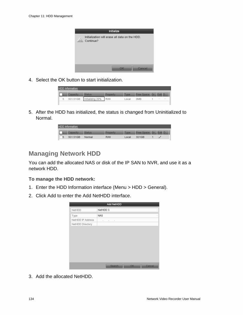
9. To initialize the HDD, click Init.
Note: Initialization removes all the data saved in the HDD.
10. Click Next to enter the Adding IP Camera interface.
11. Click Search to find online IP Camera. Select the desired IP camera, and then
click Add.
Chapter 2: Getting Started
Network Video Recorder User Manual 23
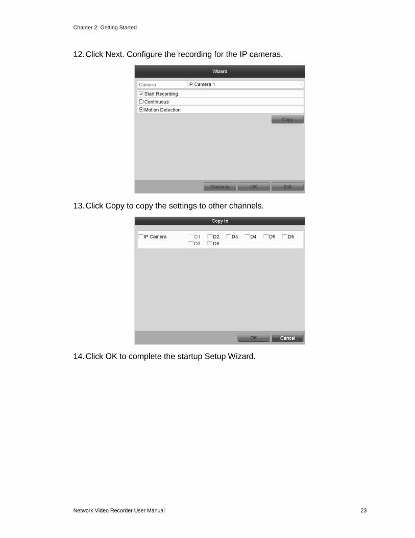
12. Click Next. Configure the recording for the IP cameras.
13. Click Copy to copy the settings to other channels.
14. Click OK to complete the startup Setup Wizard.
Chapter 2: Getting Started
24 Network Video Recorder User Manual
Adding and connecting the IP cameras
Adding the online IP cameras
The main function of the NVR is to connect and record the network cameras
video stream. Add the network camera to the connection list to get a live view
and record of the video.
Before you start, ensure that the network connection is correct. For detailed
instructions about checking and configuring the network, see “Checking network
traffic” and “Configuring network detection” on page 115.
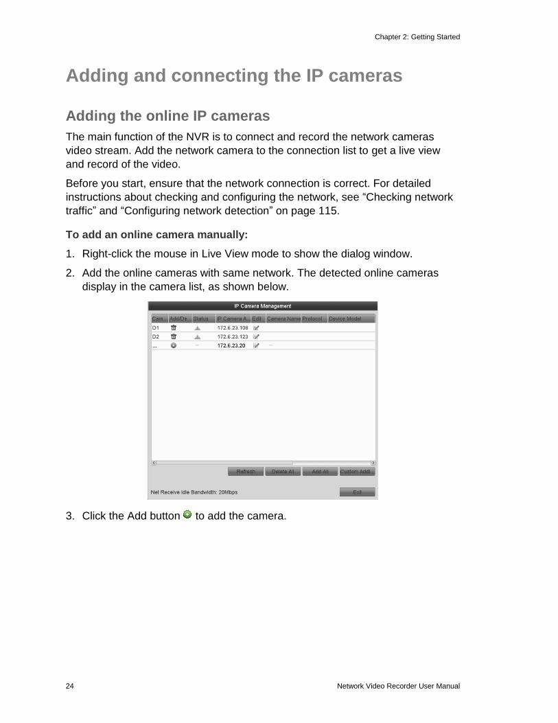
To add an online camera manually:
1. Right-click the mouse in Live View mode to show the dialog window.
2. Add the online cameras with same network. The detected online cameras
display in the camera list, as shown below.
3. Click the Add button to add the camera.
Chapter 2: Getting Started
Network Video Recorder User Manual 25
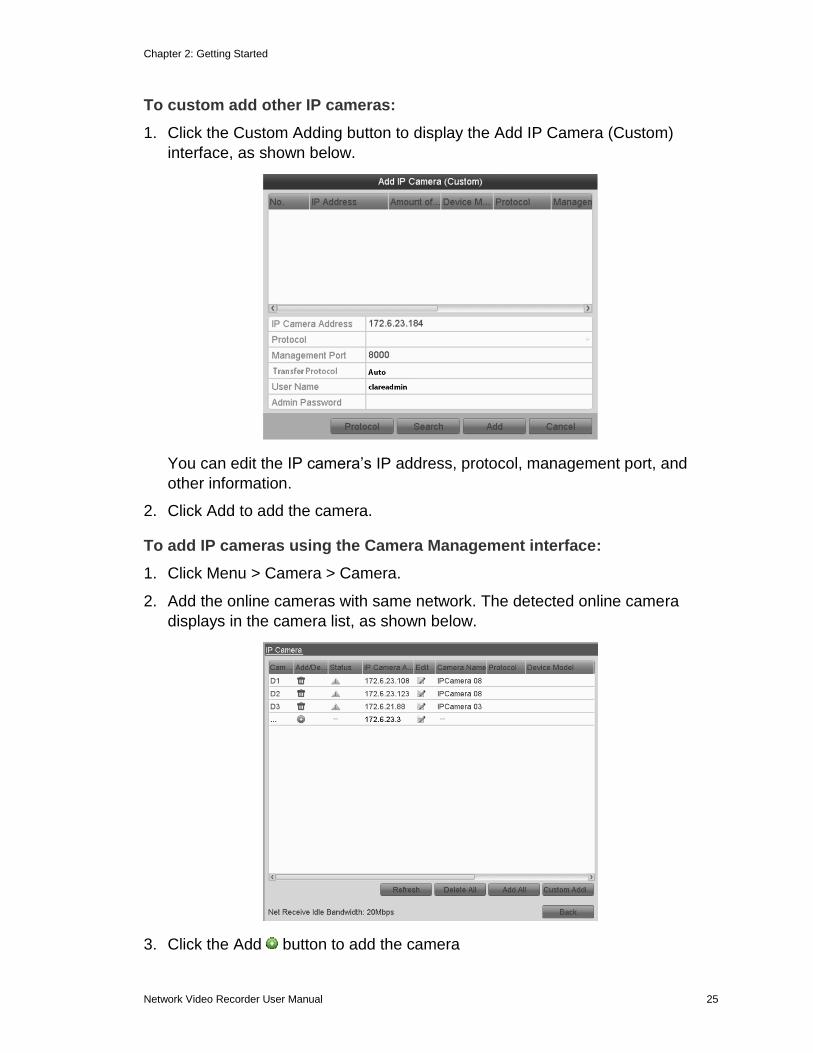
To custom add other IP cameras:
1. Click the Custom Adding button to display the Add IP Camera (Custom)
interface, as shown below.
You can edit the IP camera’s IP address, protocol, management port, and
other information.
2. Click Add to add the camera.
To add IP cameras using the Camera Management interface:
1. Click Menu > Camera > Camera.
2. Add the online cameras with same network. The detected online camera
displays in the camera list, as shown below.
3. Click the Add button to add the camera
Chapter 2: Getting Started
26 Network Video Recorder User Manual
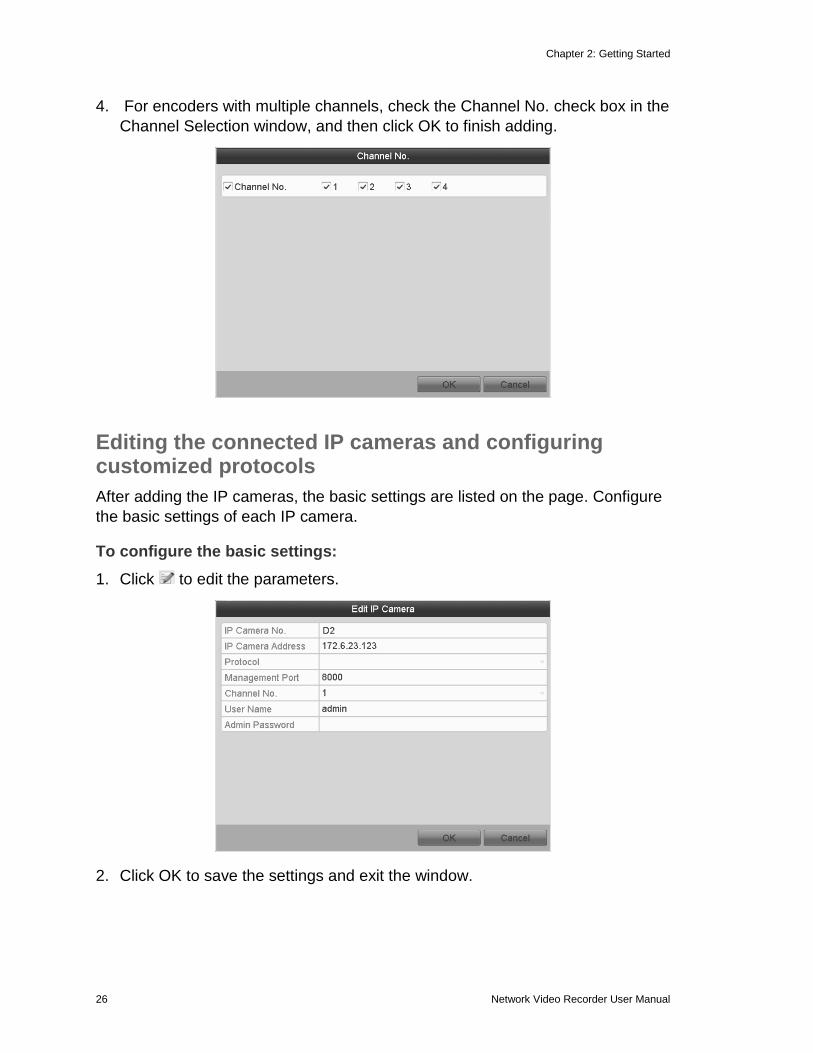
4. For encoders with multiple channels, check the Channel No. check box in the
Channel Selection window, and then click OK to finish adding.
Editing the connected IP cameras and configuring customized protocols
After adding the IP cameras, the basic settings are listed on the page. Configure
the basic settings of each IP camera.
To configure the basic settings:
1. Click to edit the parameters.
2. Click OK to save the settings and exit the window.
Chapter 2: Getting Started
Network Video Recorder User Manual 27
To edit advanced parameters:
1. Drag the horizontal scroll bar to the right side, and then click to display the
Advance Set window.
2. Edit the network information and password for the camera.
3. Click Apply to save the settings, and then click OK to exit the window.
Configuring the customized protocols
When connecting network cameras that are not configured with the standard
protocols, configure customized protocols.
Chapter 2: Getting Started
28 Network Video Recorder User Manual
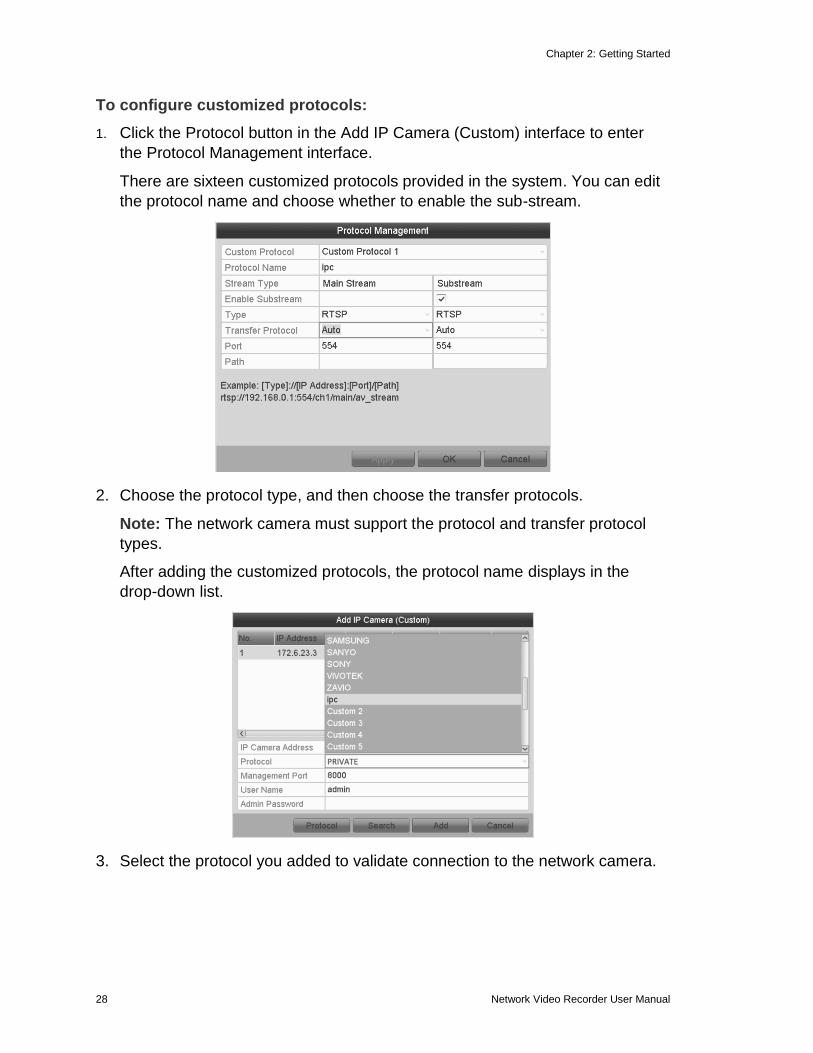
To configure customized protocols:
1. Click the Protocol button in the Add IP Camera (Custom) interface to enter
the Protocol Management interface.
There are sixteen customized protocols provided in the system. You can edit
the protocol name and choose whether to enable the sub-stream.
2. Choose the protocol type, and then choose the transfer protocols.
Note: The network camera must support the protocol and transfer protocol
types.
After adding the customized protocols, the protocol name displays in the
drop-down list.
3. Select the protocol you added to validate connection to the network camera.
Chapter 2: Getting Started
Network Video Recorder User Manual 29
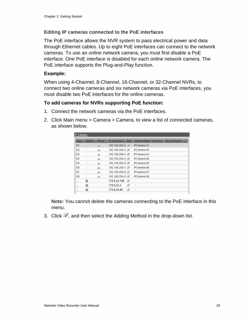
Editing IP cameras connected to the PoE interfaces
The PoE interface allows the NVR system to pass electrical power and data
through Ethernet cables. Up to eight PoE interfaces can connect to the network
cameras. To use an online network camera, you must first disable a PoE
interface. One PoE interface is disabled for each online network camera. The
PoE interface supports the Plug-and-Play function.
Example:
When using 4-Channel, 8-Channel, 16-Channel, or 32-Channel NVRs, to
connect two online cameras and six network cameras via PoE interfaces, you
must disable two PoE interfaces for the online cameras.
To add cameras for NVRs supporting PoE function:
1. Connect the network cameras via the PoE interfaces.
2. Click Main menu > Camera > Camera, to view a list of connected cameras,
as shown below.
Note: You cannot delete the cameras connecting to the PoE interface in this
menu.
3. Click , and then select the Adding Method in the drop-down list.
Chapter 2: Getting Started
30 Network Video Recorder User Manual
4. Choose one of the following.
Plug-and-Play: Connect the camera to the PoE interface. You cannot edit the
camera parameters when choosing this option. The camera’s IP address can
only be edited in the Network Configuration interface. See “Configuring
general settings” on page 103 for detailed information.
- or -
Manual: This disables the PoE interface. The current channel is used as a
normal channel and the parameters is edited.
30 Network Video Recorder User Manual
Chapter 3 Introduction to Live View
Introduction to Live View
Operations in Live View mode
The Live View mode functions are listed below.
Single Screen: Shows only one screen on the monitor.
Multi-screen: Shows multiple screens on the monitor simultaneously.
Auto-switch: The screen is auto switched to the next one. You must set the
dwell time for each screen on the configuration menu before enabling
auto-switch.
Menu > Configuration > Live View > Dwell Time.
Start Recording: This starts recording, continuous record and motion
detection record are supported.
Output Mode: Select the output mode; Standard, Bright, Gentle or Vivid.
Playback: Playback the recorded videos for current day.
Aux/Main output switch: The NVR checks the connection of the output
interfaces. The priority level for the main and aux output is HDMI > VGA >
CVBS. This means if the HDMI is used, it is the main output. If HDMI is not
used, the VGA output is set as the main output. See Table 12.
Next screen: Moves to the next screen.
Previous screen: Returns to the previous screen.
Menu: Displays the Live Mode menu.
Add IP camera: Adds an IP camera to Live Mode.
Chapter 3: Introduction to Live VIew
Network Video Recorder User Manual 31
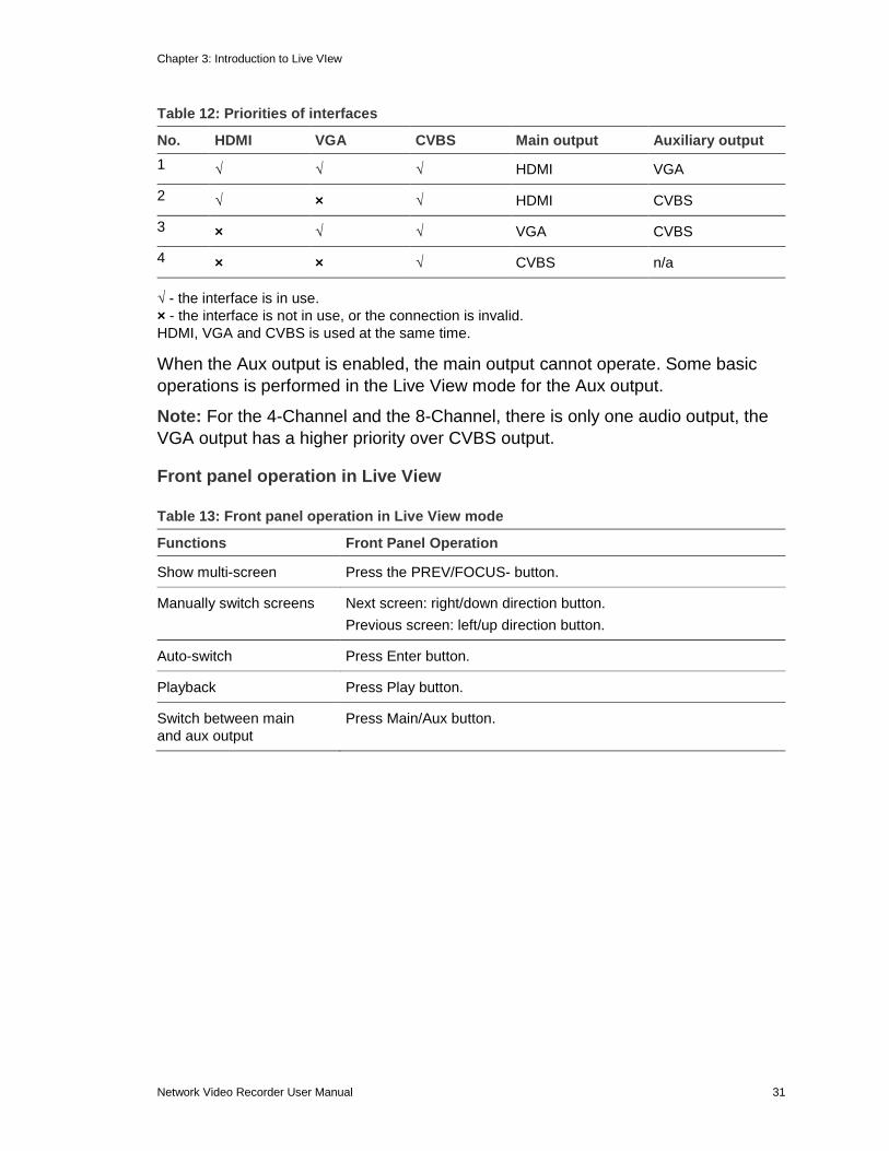
Table 12: Priorities of interfaces
No. HDMI VGA CVBS Main output Auxiliary output
1 √ √ √ HDMI VGA
2 √ × √ HDMI CVBS
3 × √ √ VGA CVBS
4 × × √ CVBS n/a
√ - the interface is in use.
× - the interface is not in use, or the connection is invalid.
HDMI, VGA and CVBS is used at the same time.
When the Aux output is enabled, the main output cannot operate. Some basic
operations is performed in the Live View mode for the Aux output.
Note: For the 4-Channel and the 8-Channel, there is only one audio output, the
VGA output has a higher priority over CVBS output.
Front panel operation in Live View
Table 13: Front panel operation in Live View mode
Functions Front Panel Operation
Show multi-screen Press the PREV/FOCUS- button.
Manually switch screens Next screen: right/down direction button.
Previous screen: left/up direction button.
Auto-switch Press Enter button.
Playback Press Play button.
Switch between main
and aux output
Press Main/Aux button.
Chapter 3: Introduction to Live View
32 Network Video Recorder User Manual
Using the mouse in Live View
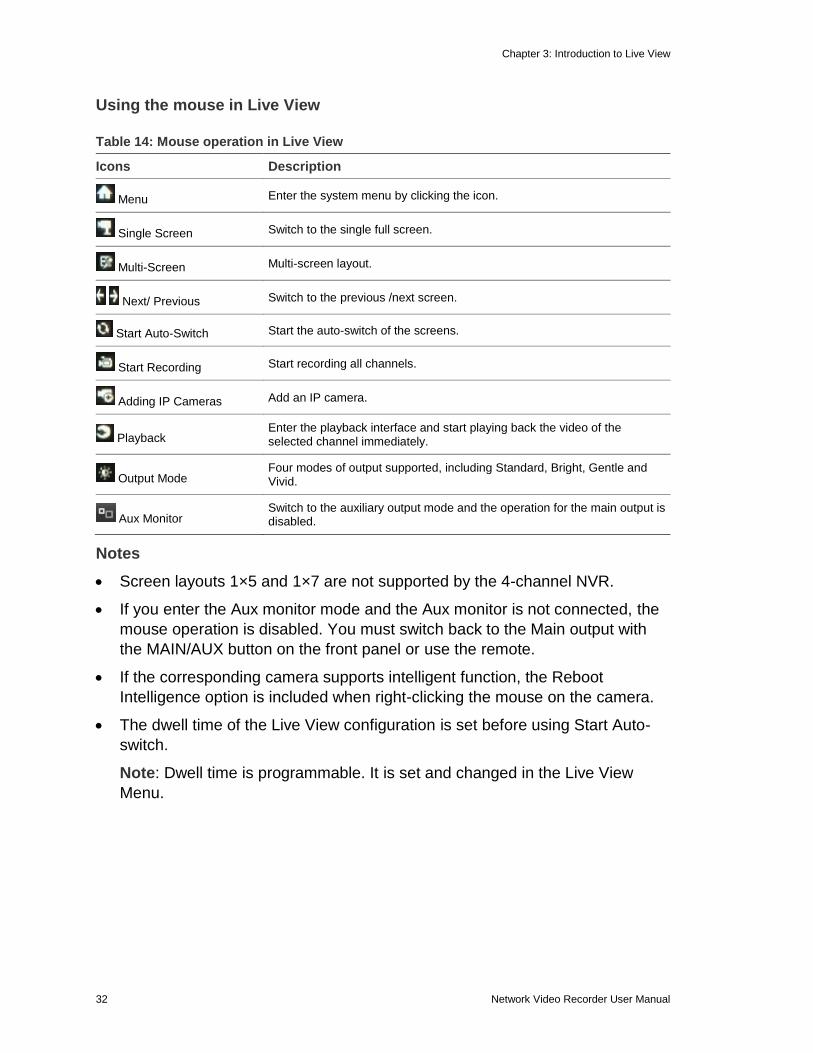
Table 14: Mouse operation in Live View
Icons Description
Menu Enter the system menu by clicking the icon.
Single Screen Switch to the single full screen.
Multi-Screen Multi-screen layout.
Next/ Previous Switch to the previous /next screen.
Start Auto-Switch Start the auto-switch of the screens.
Start Recording Start recording all channels.
Adding IP Cameras Add an IP camera.
Playback Enter the playback interface and start playing back the video of the selected channel immediately.
Output Mode Four modes of output supported, including Standard, Bright, Gentle and Vivid.
Aux Monitor Switch to the auxiliary output mode and the operation for the main output is disabled.
Notes
Screen layouts 1×5 and 1×7 are not supported by the 4-channel NVR.
If you enter the Aux monitor mode and the Aux monitor is not connected, the
mouse operation is disabled. You must switch back to the Main output with
the MAIN/AUX button on the front panel or use the remote.
If the corresponding camera supports intelligent function, the Reboot
Intelligence option is included when right-clicking the mouse on the camera.
The dwell time of the Live View configuration is set before using Start Auto-
switch.
Note: Dwell time is programmable. It is set and changed in the Live View
Menu.
Chapter 3: Introduction to Live VIew
Network Video Recorder User Manual 33
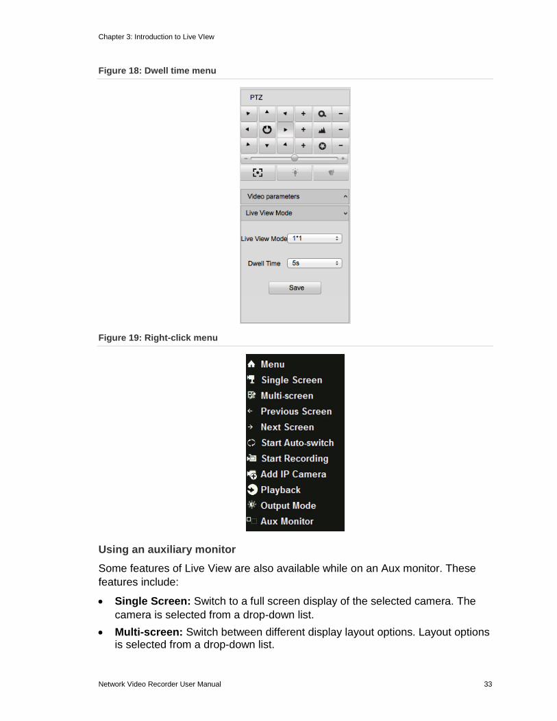
Figure 18: Dwell time menu
Figure 19: Right-click menu
Using an auxiliary monitor
Some features of Live View are also available while on an Aux monitor. These
features include:
Single Screen: Switch to a full screen display of the selected camera. The
camera is selected from a drop-down list.
Multi-screen: Switch between different display layout options. Layout options is selected from a drop-down list.
Chapter 3: Introduction to Live View
34 Network Video Recorder User Manual
Next Screen: When displaying less than the maximum number of cameras in Live View, clicking this feature switches to the next set of displays.
Playback: Enters Playback mode.
PTZ: Enters the PTZ Control mode.
Main Monitor: Enters the Main operation mode.
Note: In the Live View mode of the main output monitor, the menu operation is not available when the Aux output mode is enabled.
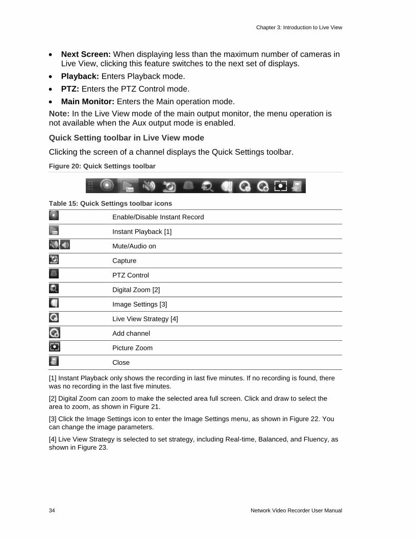
Quick Setting toolbar in Live View mode
Clicking the screen of a channel displays the Quick Settings toolbar.
Figure 20: Quick Settings toolbar
Table 15: Quick Settings toolbar icons
Enable/Disable Instant Record
Instant Playback [1]
/ Mute/Audio on
Capture
PTZ Control
Digital Zoom [2]
Image Settings [3]
Live View Strategy [4]
Add channel
Picture Zoom
Close
[1] Instant Playback only shows the recording in last five minutes. If no recording is found, there
was no recording in the last five minutes.
[2] Digital Zoom can zoom to make the selected area full screen. Click and draw to select the
area to zoom, as shown in Figure 21.
[3] Click the Image Settings icon to enter the Image Settings menu, as shown in Figure 22. You
can change the image parameters.
[4] Live View Strategy is selected to set strategy, including Real-time, Balanced, and Fluency, as
shown in Figure 23.
Chapter 3: Introduction to Live VIew
Network Video Recorder User Manual 35
Figure 21: Digital zoom
Figure 22: Image settings - preset
Figure 23: Live View Strategy
Adjusting Live View settings
You can customize the Live View settings according to your different needs. You
can configure the output interface, dwell time, mute or turn on the audio, and
view the screen number for each channel, etc.
Chapter 3: Introduction to Live View
36 Network Video Recorder User Manual
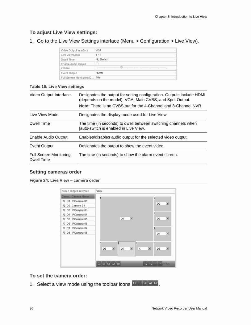
To adjust Live View settings:
1. Go to the Live View Settings interface (Menu > Configuration > Live View).
Table 16: Live View settings
Video Output Interface Designates the output for setting configuration. Outputs include HDMI
(depends on the model), VGA, Main CVBS, and Spot Output.
Note: There is no CVBS out for the 4-Channel and 8-Channel NVR.
Live View Mode Designates the display mode used for Live View.
Dwell Time The time (in seconds) to dwell between switching channels when
|auto-switch is enabled in Live View.
Enable Audio Output Enables/disables audio output for the selected video output.
Event Output Designates the output to show the event video.
Full Screen Monitoring
Dwell Time
The time (in seconds) to show the alarm event screen.
Setting cameras order
Figure 24: Live View – camera order
To set the camera order:
1. Select a view mode using the toolbar icons .
Chapter 3: Introduction to Live VIew
Network Video Recorder User Manual 37
2. Select the small window, and then double-click the channel number to display
the channel in the window.
3. Click the button to start live view for all the channels, and then click to
stop all live viewing.
4. Click the Apply button to save the setting.
Channel-zero encoding
Sometimes a remote view of channels in real time from a web browser or CMS
(Client Management System) software is necessary. In order to decrease the
bandwidth requirement without affecting image quality, channel-zero encoding is
supported.
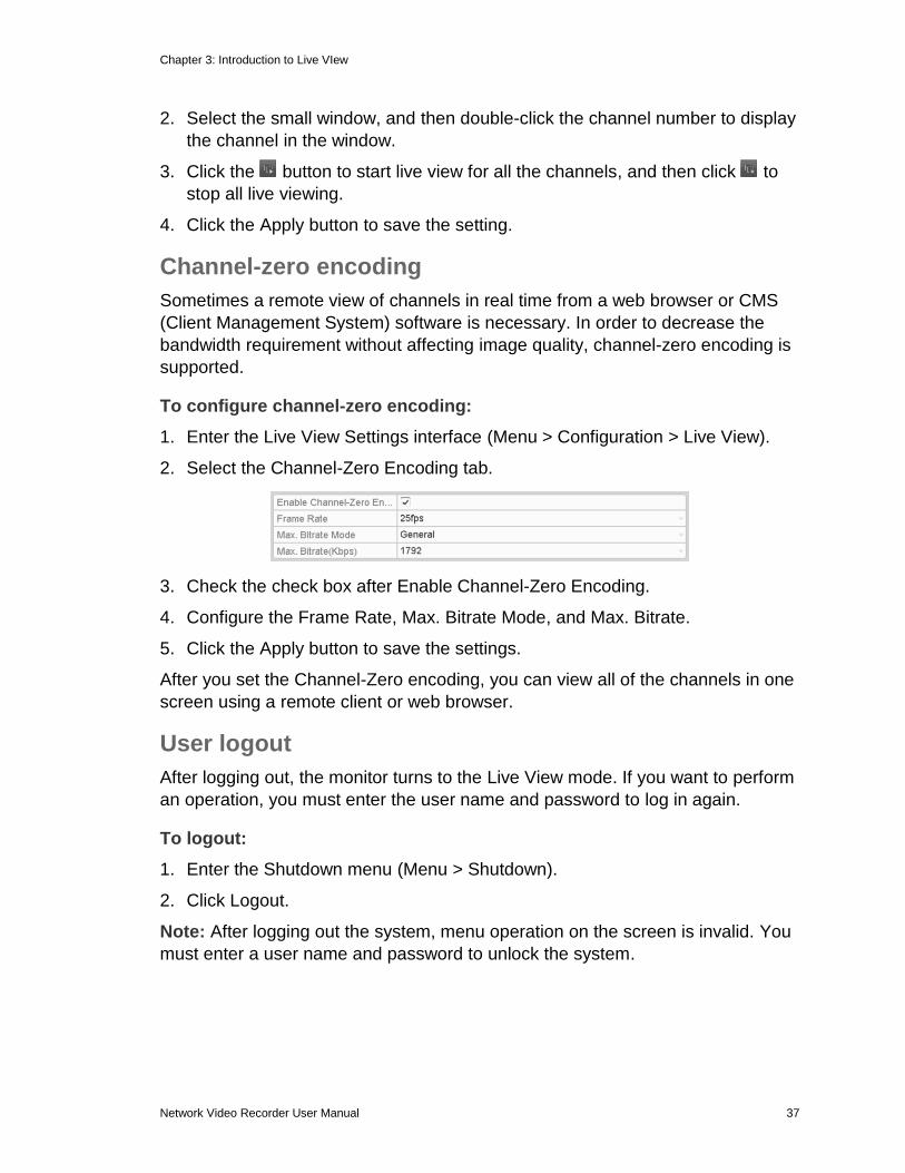
To configure channel-zero encoding:
1. Enter the Live View Settings interface (Menu > Configuration > Live View).
2. Select the Channel-Zero Encoding tab.
3. Check the check box after Enable Channel-Zero Encoding.
4. Configure the Frame Rate, Max. Bitrate Mode, and Max. Bitrate.
5. Click the Apply button to save the settings.
After you set the Channel-Zero encoding, you can view all of the channels in one
screen using a remote client or web browser.
User logout
After logging out, the monitor turns to the Live View mode. If you want to perform
an operation, you must enter the user name and password to log in again.
To logout:
1. Enter the Shutdown menu (Menu > Shutdown).
2. Click Logout.
Note: After logging out the system, menu operation on the screen is invalid. You
must enter a user name and password to unlock the system.
Network Video Recorder User Manual 38
Chapter 4 Configuring PTZ Settings
Configuring PTZ settings Follow the procedure to set the parameters for PTZ (Pan, Tilt, Zoom). You should
configure the PTZ parameters before you control the PTZ camera.
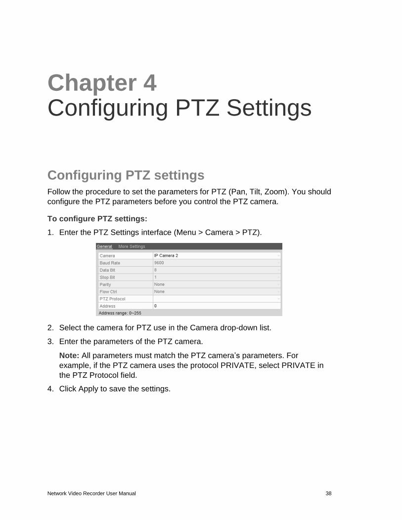
To configure PTZ settings:
1. Enter the PTZ Settings interface (Menu > Camera > PTZ).
2. Select the camera for PTZ use in the Camera drop-down list.
3. Enter the parameters of the PTZ camera.
Note: All parameters must match the PTZ camera’s parameters. For
example, if the PTZ camera uses the protocol PRIVATE, select PRIVATE in
the PTZ Protocol field.
4. Click Apply to save the settings.
Chapter 4: Configuring PTZ Settings
Network Video Recorder User Manual 39
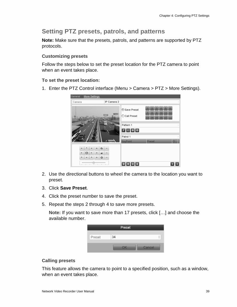
Setting PTZ presets, patrols, and patterns
Note: Make sure that the presets, patrols, and patterns are supported by PTZ
protocols.
Customizing presets
Follow the steps below to set the preset location for the PTZ camera to point
when an event takes place.
To set the preset location:
1. Enter the PTZ Control interface (Menu > Camera > PTZ > More Settings).
2. Use the directional buttons to wheel the camera to the location you want to
preset.
3. Click Save Preset.
4. Click the preset number to save the preset.
5. Repeat the steps 2 through 4 to save more presets.
Note: If you want to save more than 17 presets, click […] and choose the
available number.
Calling presets
This feature allows the camera to point to a specified position, such as a window,
when an event takes place.
Chapter 4: Configuring PTZ Settings
40 Network Video Recorder User Manual
To call preset in the PTZ setting interface:
1. Enter the PTZ Control interface (Menu > Camera > PTZ > More Settings).
2. Click Call Preset.
3. Choose the preset number.
To call preset in Live View mode:
1. Press the PTZ button on the front panel, or click the PTZ Control icon in
the Quick Setting bar, to enter the PTZ setting menu in Live View mode.
2. Choose Camera in the list on the menu.
3. Double-click the preset in the list to call it.
Customizing patrols
You can set patrols to move the PTZ to different key points and have it stay there
for a set duration before moving on to the next key point. The key points
correspond to the presets.
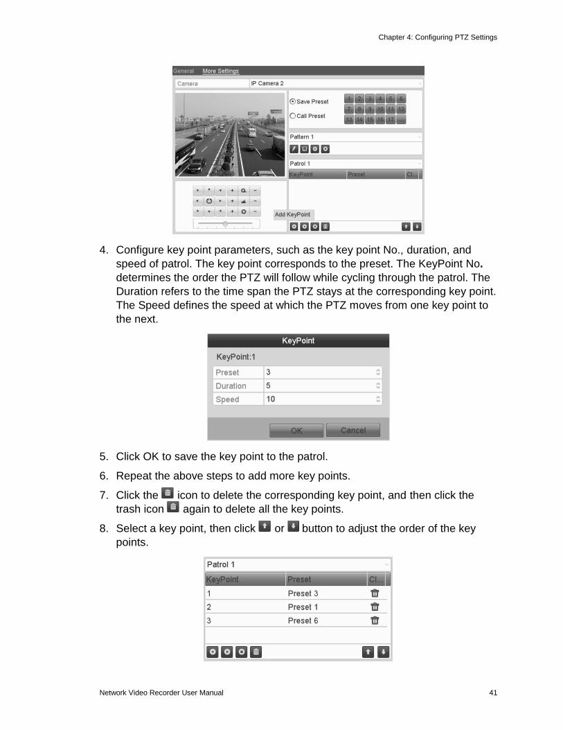
To customize patrols:
1. Enter the PTZ Control interface (Menu > Camera > PTZ > More Settings).
2. Select patrol number in the drop-down list of patrols.
3. Click under the Patrol option box to add key points for the patrol.
Chapter 4: Configuring PTZ Settings
Network Video Recorder User Manual 41
4. Configure key point parameters, such as the key point No., duration, and
speed of patrol. The key point corresponds to the preset. The KeyPoint No.
determines the order the PTZ will follow while cycling through the patrol. The
Duration refers to the time span the PTZ stays at the corresponding key point.
The Speed defines the speed at which the PTZ moves from one key point to
the next.
5. Click OK to save the key point to the patrol.
6. Repeat the above steps to add more key points.
7. Click the icon to delete the corresponding key point, and then click the
trash icon again to delete all the key points.
8. Select a key point, then click or button to adjust the order of the key
points.
Chapter 4: Configuring PTZ Settings
42 Network Video Recorder User Manual
Calling patrols
Calling a patrol makes the PTZ camera move according to the predefined patrol
path.
To set calling patrol in the PTZ setting interface:
1. Browse to the PTZ setting interface (Menu > Camera > PTZ > More Settings).
2. Select the patrol number, and then click to call the patrol.
3. Click to stop it.
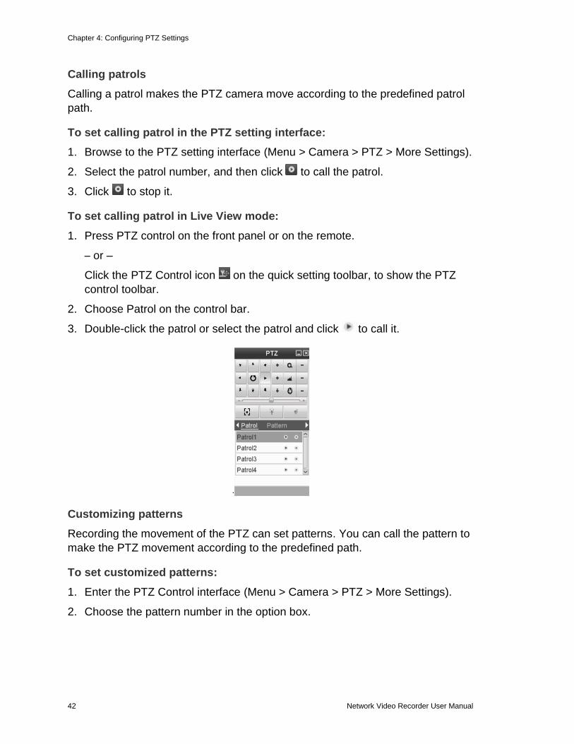
To set calling patrol in Live View mode:
1. Press PTZ control on the front panel or on the remote.
– or –
Click the PTZ Control icon on the quick setting toolbar, to show the PTZ
control toolbar.
2. Choose Patrol on the control bar.
3. Double-click the patrol or select the patrol and click to call it.
Customizing patterns
Recording the movement of the PTZ can set patterns. You can call the pattern to
make the PTZ movement according to the predefined path.
To set customized patterns:
1. Enter the PTZ Control interface (Menu > Camera > PTZ > More Settings).
2. Choose the pattern number in the option box.
Chapter 4: Configuring PTZ Settings
Network Video Recorder User Manual 43
3. Click and use your mouse to drag the image or click the eight directional buttons in the control box under the image to move the PTZ camera.
4. The movement of the PTZ is recorded as the pattern.
5. Click to save the pattern.
Calling patterns
Follow the procedure to move the PTZ camera according to the predefined
patterns.
To set a calling pattern in the PTZ setting interface:
1. Enter the PTZ Control interface (Menu > Camera > PTZ > More Settings).
2. Select the pattern number.
3. Click . The PTZ moves according to the pattern. Click to stop it.
To set a calling pattern in Live View mode:
1. In the Live View mode, press PTZ control on the front panel or on the remote control.
– or –
Click PTZ Control icon on the quick setting panel.
2. Choose Pattern on the control bar.
3. Double-click the pattern or select the pattern and click to call it.
Chapter 4: Configuring PTZ Settings
44 Network Video Recorder User Manual
PTZ control panel
In the Live View mode, press the PTZ Control button on the front panel, on the
remote control, or choose the PTZ Control icon to enter the PTZ panel.
Figure 25: PZT panel
Table 17: PZT panel icons
Direction and auto-cycle buttons
Zoom+, Focus+, Iris+
Zoom-, Focus-, Iris-
The speed of the PTZ movement
Auto focus
Light on/off
Wiper on/off
Preset
Patrol
Pattern
Menu
Previous item
Next item
Start pattern/patrol
Stop the patrol or pattern movement
Minimize windows
Exit
Network Video Recorder User Manual 45
Chapter 5 Record and Capture Settings
Configuring parameters By configuring the encoding parameters you can define the parameters that
affect the image quality, such as the transmission stream type, the resolution,
and so on.
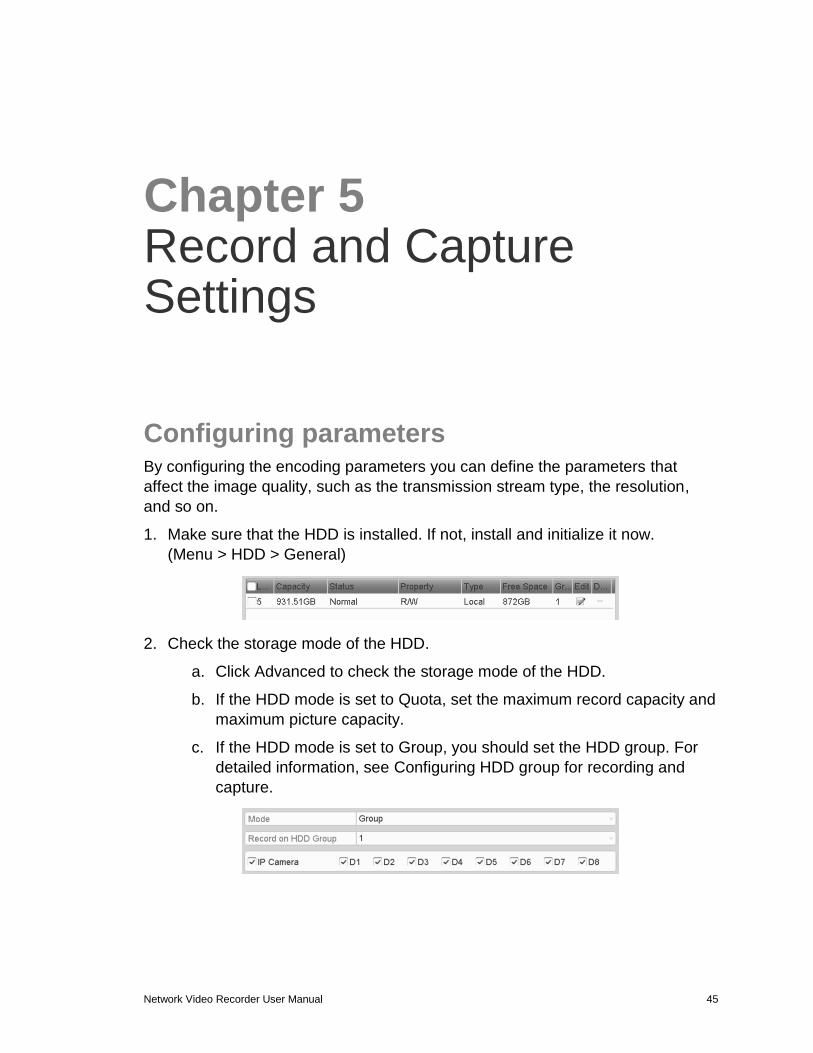
1. Make sure that the HDD is installed. If not, install and initialize it now.
(Menu > HDD > General)
2. Check the storage mode of the HDD.
a. Click Advanced to check the storage mode of the HDD.
b. If the HDD mode is set to Quota, set the maximum record capacity and
maximum picture capacity.
c. If the HDD mode is set to Group, you should set the HDD group. For
detailed information, see Configuring HDD group for recording and
capture.
Chapter 5: Record and Capture Settings
46 Network Video Recorder User Manual
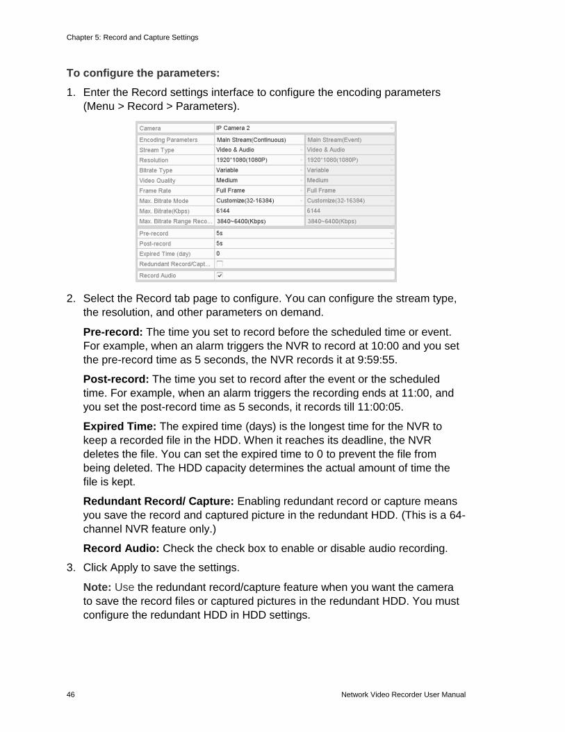
To configure the parameters:
1. Enter the Record settings interface to configure the encoding parameters
(Menu > Record > Parameters).
2. Select the Record tab page to configure. You can configure the stream type,
the resolution, and other parameters on demand.
Pre-record: The time you set to record before the scheduled time or event.
For example, when an alarm triggers the NVR to record at 10:00 and you set
the pre-record time as 5 seconds, the NVR records it at 9:59:55.
Post-record: The time you set to record after the event or the scheduled
time. For example, when an alarm triggers the recording ends at 11:00, and
you set the post-record time as 5 seconds, it records till 11:00:05.
Expired Time: The expired time (days) is the longest time for the NVR to
keep a recorded file in the HDD. When it reaches its deadline, the NVR
deletes the file. You can set the expired time to 0 to prevent the file from
being deleted. The HDD capacity determines the actual amount of time the
file is kept.
Redundant Record/ Capture: Enabling redundant record or capture means
you save the record and captured picture in the redundant HDD. (This is a 64-
channel NVR feature only.)
Record Audio: Check the check box to enable or disable audio recording.
3. Click Apply to save the settings.
Note: Use the redundant record/capture feature when you want the camera
to save the record files or captured pictures in the redundant HDD. You must
configure the redundant HDD in HDD settings.
Chapter 5: Record and Capture Settings
Network Video Recorder User Manual 47
4. Enter the Sub-stream tab page.
5. Configure the parameters of the camera.
6. Click Apply to save the settings.
7. Select the Capture tab, and then configure the settings.
8. Click Apply to save the settings.
Note: The interval is the time between two capturing actions. You can
configure all the parameters on this menu.
Configuring record/capture schedule
Set the record schedule to automatically start and stop the recording, based on
the configured schedule.
In this chapter, we use the record schedule procedure as an example. You can
apply the same procedure to configure a schedule for both recording and
capture. To schedule the automatic capture, you must click the Capture tab in the
Schedule interface.
To configure the schedule:
1. Enter the Record Schedule interface (Menu > Record/Capture > Schedule)
2. Select Record/Capture Schedule.
Chapter 5: Record and Capture Settings
48 Network Video Recorder User Manual
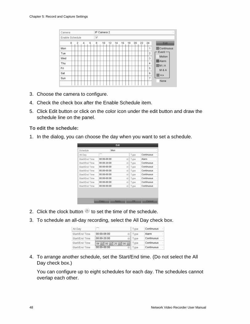
3. Choose the camera to configure.
4. Check the check box after the Enable Schedule item.
5. Click Edit button or click on the color icon under the edit button and draw the
schedule line on the panel.
To edit the schedule:
1. In the dialog, you can choose the day when you want to set a schedule.
2. Click the clock button to set the time of the schedule.
3. To schedule an all-day recording, select the All Day check box.
4. To arrange another schedule, set the Start/End time. (Do not select the All
Day check box.)
You can configure up to eight schedules for each day. The schedules cannot
overlap each other.
Chapter 5: Record and Capture Settings
Network Video Recorder User Manual 49
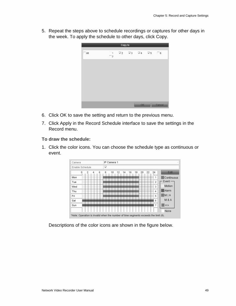
5. Repeat the steps above to schedule recordings or captures for other days in
the week. To apply the schedule to other days, click Copy.
6. Click OK to save the setting and return to the previous menu.
7. Click Apply in the Record Schedule interface to save the settings in the
Record menu.
To draw the schedule:
1. Click the color icons. You can choose the schedule type as continuous or
event.
Descriptions of the color icons are shown in the figure below.
Chapter 5: Record and Capture Settings
50 Network Video Recorder User Manual
2. Click Apply to validate the settings.
3. To use the same settings in other channels, click Copy, and then choose the
channel to copy to.
Configuring motion detection record and capture
Follow the steps to set the motion detection parameters. In the Live View mode,
once a motion detection event takes place, the NVR can analyze it and respond.
Enabling the motion detection function can trigger certain channels to start
recording, trigger full screen monitoring, audio warning, notify the surveillance
center, and so on. In this chapter, you can follow the steps to schedule a
recording triggered by detected motion.
Chapter 5: Record and Capture Settings
Network Video Recorder User Manual 51
To configure motion detection:
1. Enter the Motion Detection interface (Menu > Camera > Motion).
2. Choose camera you want to configure.
3. Check the check box after Enable Motion Detection.
4. Using your mouse, drag and draw the area for motion detection. If you want to set the motion detection for the entire area viewed by the camera, click Full Screen. To clear the motion detection area, click Clear.
5. Click Settings to display the Settings dialog.
6. Select the channels you want the motion detection event to trigger recording.
Chapter 5: Record and Capture Settings
52 Network Video Recorder User Manual
7. Click Apply to save the settings.
8. Click OK to return to the previous menu.
9. Exit the Motion Detection menu.
10. Edit the Motion Detection Record Schedule.
Configuring alarm triggered record and capture
To configure alarm triggered recording or capture:
1. Enter the Alarm setting interface (Menu > Configuration > Alarm).
2. Click Alarm Input.
3. Select Alarm Input number and configure alarm parameters.
4. Choose N.O (normally open) or N.C (normally closed) for alarm type.
5. Select the Enable check box.
6. Click Settings.
Chapter 5: Record and Capture Settings
Network Video Recorder User Manual 53
7. Choose the alarm triggered recording channel.
8. Click the check box to select a channel.
9. Click Apply to save settings.
10. Click OK to return to the previous menu.
11. Repeat the above steps to configure other alarm input parameters.
12. If you want to apply the settings to other alarm inputs, click Copy and choose
the alarm input number.
13. Edit the Alarm triggered record in the Record/Capture Schedule setting
interface.
Chapter 5: Record and Capture Settings
54 Network Video Recorder User Manual
Manual record and continuous capture
Follow the steps to set parameters for the manual record and continuous
capture. Using manual record and continuous capture, you must manually cancel
the record and capture.
To enable manual record:
1. Enter the Manual settings interface (Menu > Manual).
- or -
Press the REC/SHOT button on the front panel.
2. To enable manual record, select Record on the left bar.
3. Click the status button before the desired camera number to change OFF to
ON.
To disable manual record:
1. Click the status button to change ON to OFF.
Note: The green ON icon indicates that the channel is configured in the
record schedule. After rebooting all the manual records that were enabled are
canceled.
To enable continuous capture:
1. Select Continuous Capture on the left bar.
2. Click the status button before camera number to change OFF to ON.
To disable continuous capture:
1. Click the status button to change ON to OFF.
Note: The green ON icon indicates that the channel is configured to a capture
schedule. After rebooting, all continuous captures are canceled.
Chapter 5: Record and Capture Settings
Network Video Recorder User Manual 55
Configuring holiday record and capture
Follow the steps below to configure the record or capture schedule for holidays.
You may have different plans for recording and capture on holidays.
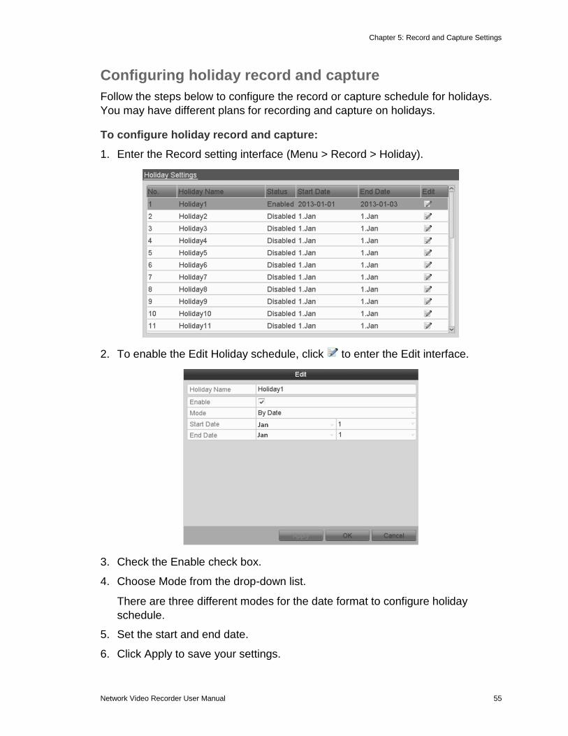
To configure holiday record and capture:
1. Enter the Record setting interface (Menu > Record > Holiday).
2. To enable the Edit Holiday schedule, click to enter the Edit interface.
3. Check the Enable check box.
4. Choose Mode from the drop-down list.
There are three different modes for the date format to configure holiday
schedule.
5. Set the start and end date.
6. Click Apply to save your settings.
Chapter 5: Record and Capture Settings
56 Network Video Recorder User Manual
7. Click OK to exit the Edit interface.
8. Enter the Record/Capture Schedule interface and edit the holiday recording
schedule.
Configuring redundant recording and capture
Enable redundant recording and capture to save the record files and captured
pictures in the R/W HDD and in the redundant HDD, if available. This will
enhance the data safety and reliability.
To configure redundant recording and capture:
1. Enter HDD Information interface (Menu > HDD).
2. Select the HDD and click to enter the Local HDD Settings interface.
3. Set the HDD property to Redundancy.
4. Click Apply to save the settings.
5. Click OK to return to the previous menu.
Note: Prior to setting the HDD property to Redundant, set the Storage mode to Group. Read/Write status is required in another HDD
6. Enter the Record setting interface (Menu > Record > Parameters).
7. Select Record tab.
Chapter 5: Record and Capture Settings
Network Video Recorder User Manual 57
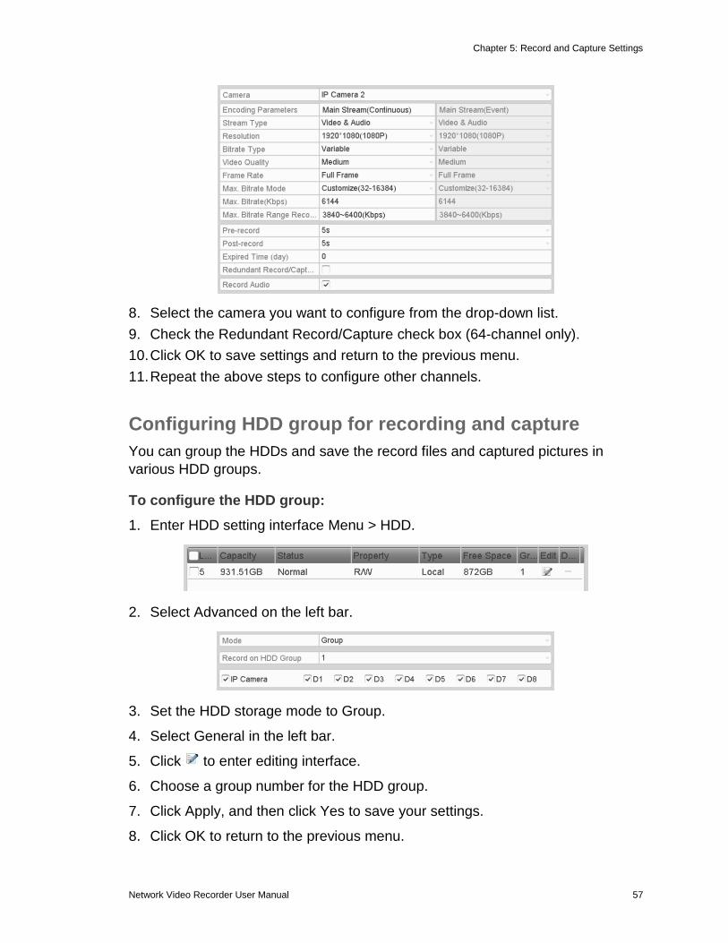
8. Select the camera you want to configure from the drop-down list.
9. Check the Redundant Record/Capture check box (64-channel only).
10. Click OK to save settings and return to the previous menu.
11. Repeat the above steps to configure other channels.
Configuring HDD group for recording and capture
You can group the HDDs and save the record files and captured pictures in
various HDD groups.
To configure the HDD group:
1. Enter HDD setting interface Menu > HDD.
2. Select Advanced on the left bar.
3. Set the HDD storage mode to Group.
4. Select General in the left bar.
5. Click to enter editing interface.
6. Choose a group number for the HDD group.
7. Click Apply, and then click Yes to save your settings.
8. Click OK to return to the previous menu.
Chapter 5: Record and Capture Settings
58 Network Video Recorder User Manual
9. Repeat the above steps to configure more HDD groups.
To choose the channels that you want to save:
1. Select Advanced on the left bar.
2. Choose Group number in the drop-down list of Record on HDD Group
3. Check the channels you want to save in this group.
4. Click Apply to save settings.
Note: After configuring the HDD groups, you can configure the Recording and
Capture settings. Follow “Configuring parameters” on page 45
Files protection
You can lock the recorded files or set the HDD property to Read-only to protect
the files from being overwritten.
To lock the files:
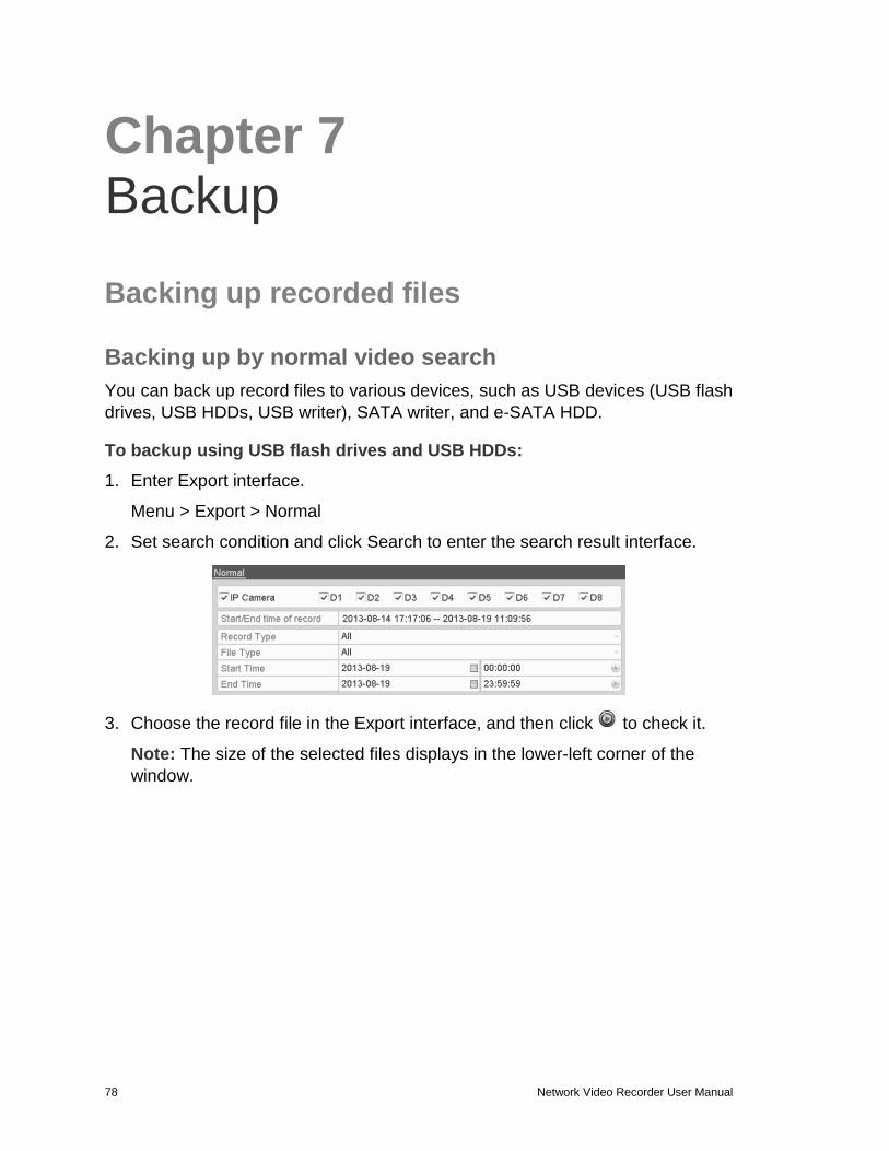
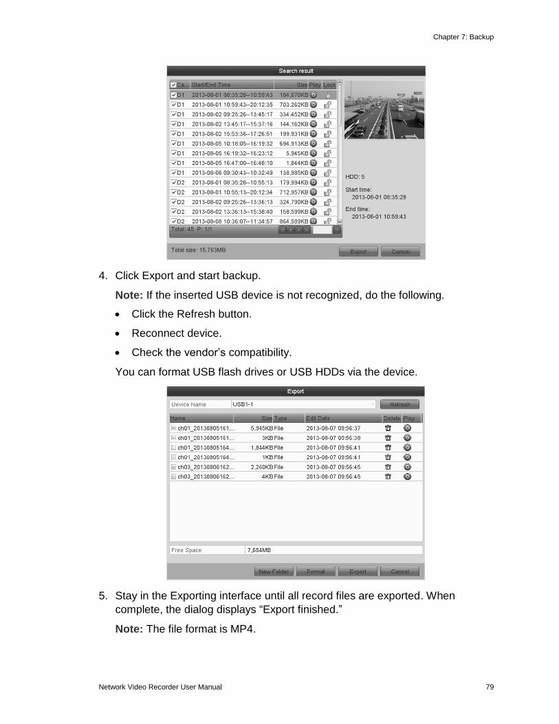
1. Enter Export setting interface (Menu > Export).
2. Select the channels you want to investigate by selecting the corresponding
check box.
3. Configure the record type, file type start/end time.
4. Click Search to show the results.
Chapter 5: Record and Capture Settings
Network Video Recorder User Manual 59
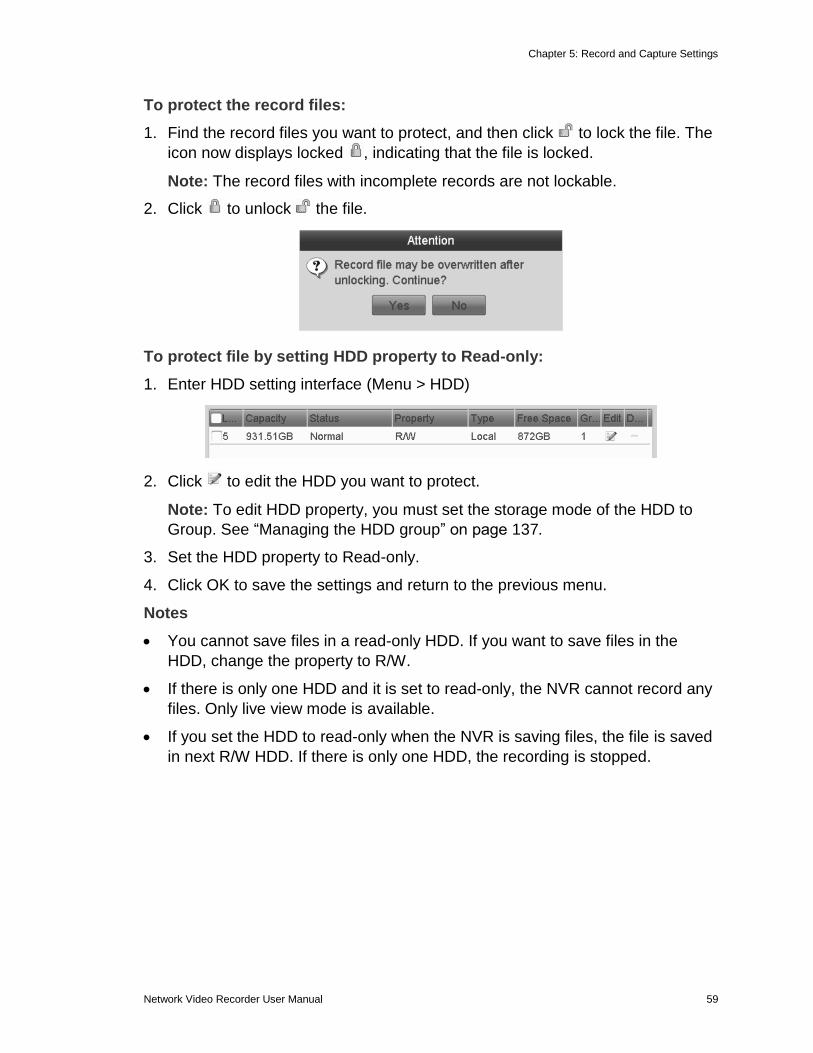
To protect the record files:
1. Find the record files you want to protect, and then click to lock the file. The
icon now displays locked , indicating that the file is locked.
Note: The record files with incomplete records are not lockable.
2. Click to unlock the file.
To protect file by setting HDD property to Read-only:
1. Enter HDD setting interface (Menu > HDD)
2. Click to edit the HDD you want to protect.
Note: To edit HDD property, you must set the storage mode of the HDD to
Group. See “Managing the HDD group” on page 137.
3. Set the HDD property to Read-only.
4. Click OK to save the settings and return to the previous menu.
Notes
You cannot save files in a read-only HDD. If you want to save files in the
HDD, change the property to R/W.
If there is only one HDD and it is set to read-only, the NVR cannot record any
files. Only live view mode is available.
If you set the HDD to read-only when the NVR is saving files, the file is saved
in next R/W HDD. If there is only one HDD, the recording is stopped.
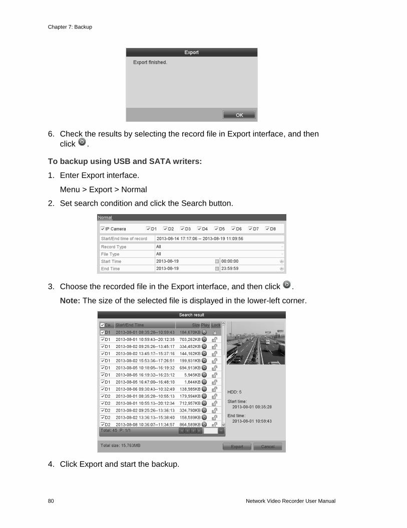
Network Video Recorder User Manual 61
Chapter 6 Playback
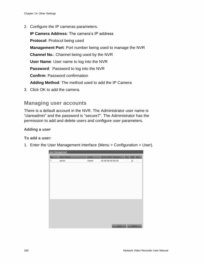
Playing back record files
Playing back by channel
Play back the recorded video files of a specific channel in the Live View mode.
You have two playback options for play back.
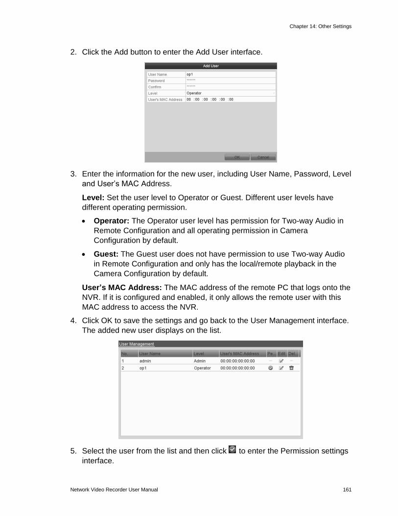
Option 1
1. Click in the quick setting toolbar, to choose a channel in Live View mode.
Note: In instant playback mode, only record files recorded during the last five
minutes on this channel are played back.
Option 2
1. Enter the Playback interface.
2. Click in the right-click menu.
3. On the front panel, press the PLAY button to play back record files for the
channel in single-screen Live View mode.
4. Under multi-screen Live View mode, the recorded files are played back.
Chapter 6: Playback
62 Network Video Recorder User Manual
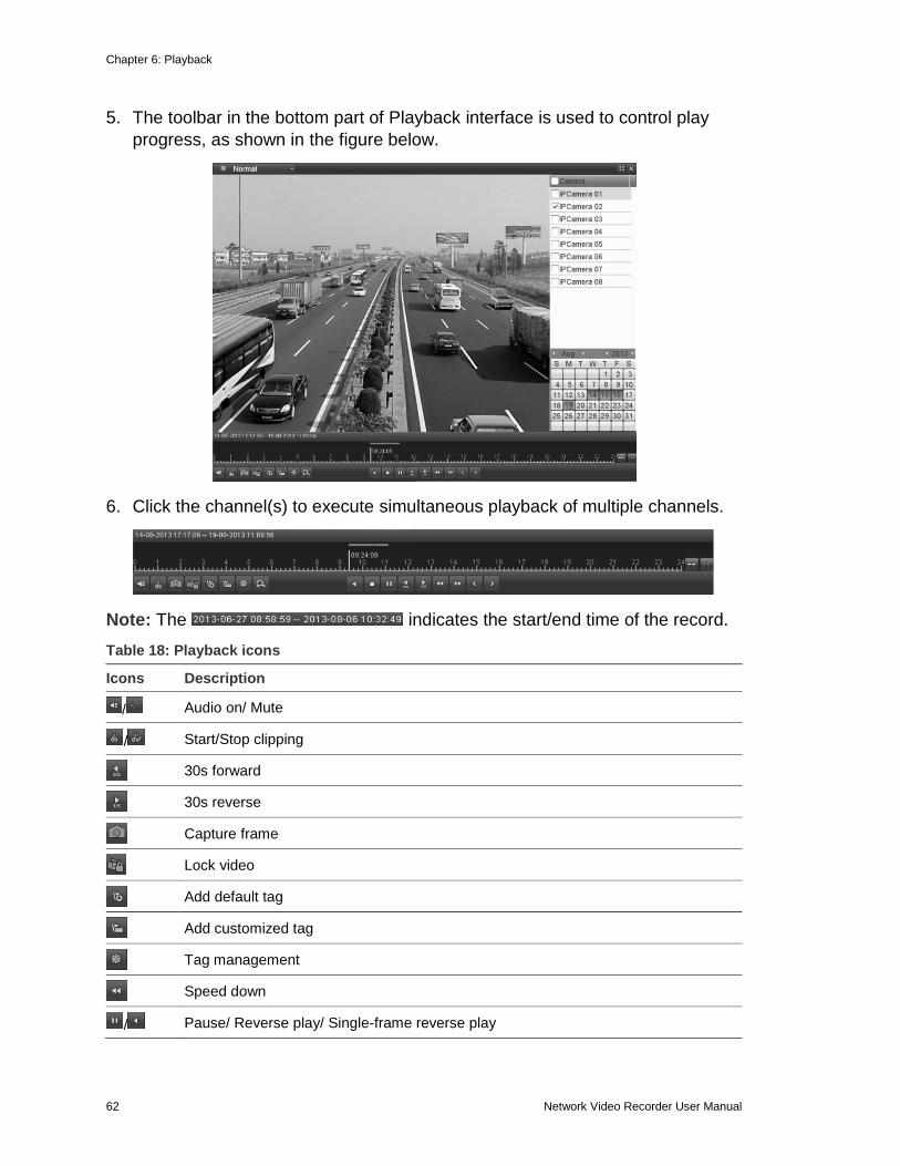
5. The toolbar in the bottom part of Playback interface is used to control play
progress, as shown in the figure below.
6. Click the channel(s) to execute simultaneous playback of multiple channels.
Note: The indicates the start/end time of the record.
Table 18: Playback icons
Icons Description
/ Audio on/ Mute
/ Start/Stop clipping
30s forward
30s reverse
Capture frame
Lock video
Add default tag
Add customized tag
Tag management
Speed down
/ Pause/ Reverse play/ Single-frame reverse play
Chapter 6: Playback
Network Video Recorder User Manual 63
/ Pause/ Play/ Single-frame play
/ Scaling up/down the time line
Speed up
Previous day
Next day
Full Screen
Exit
Stop
Digital Zoom
Video type
Process bar
Note: On the Playback progress bar, use the mouse to click any point of the
progress bar or drag the progress bar to locate special frames.
Playing back by time
Play back video files recorded in a specified time duration. Multi-channel
simultaneous playback and channel switch are supported.
To play back by time:
1. Enter the playback interface (Menu > Playback).
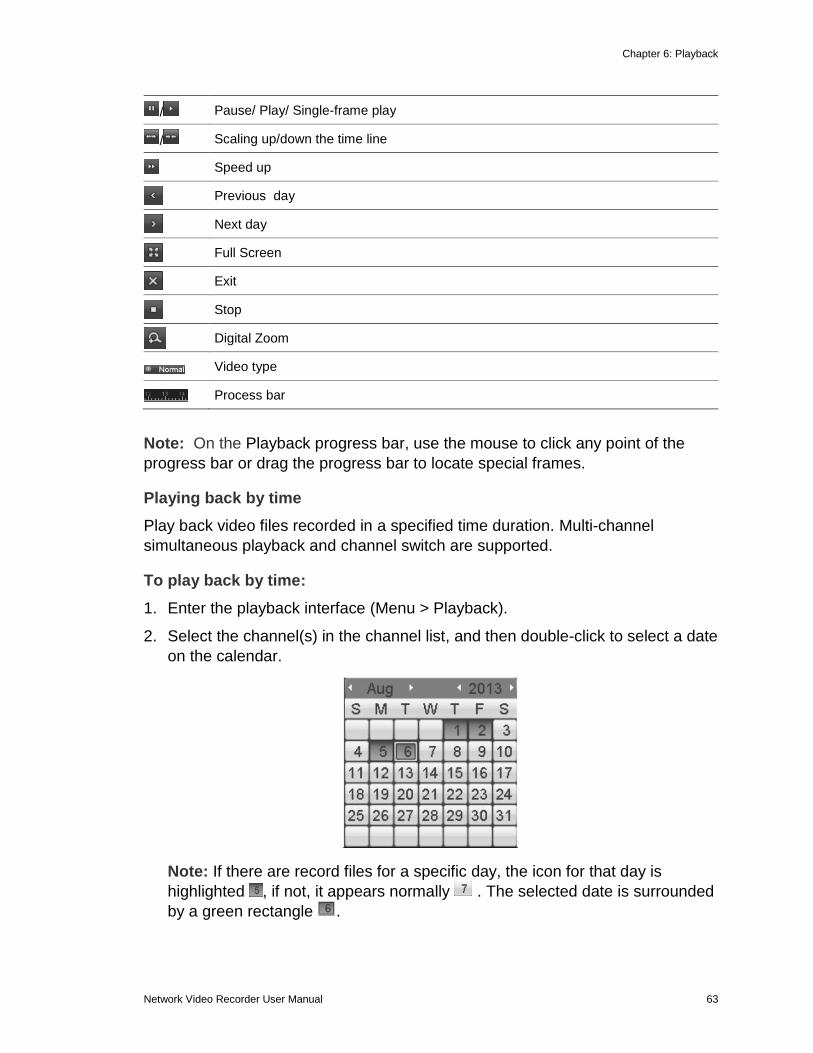
2. Select the channel(s) in the channel list, and then double-click to select a date
on the calendar.
Note: If there are record files for a specific day, the icon for that day is
highlighted , if not, it appears normally . The selected date is surrounded
by a green rectangle .
Chapter 6: Playback
64 Network Video Recorder User Manual
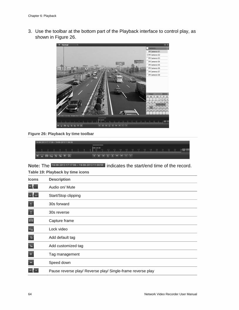
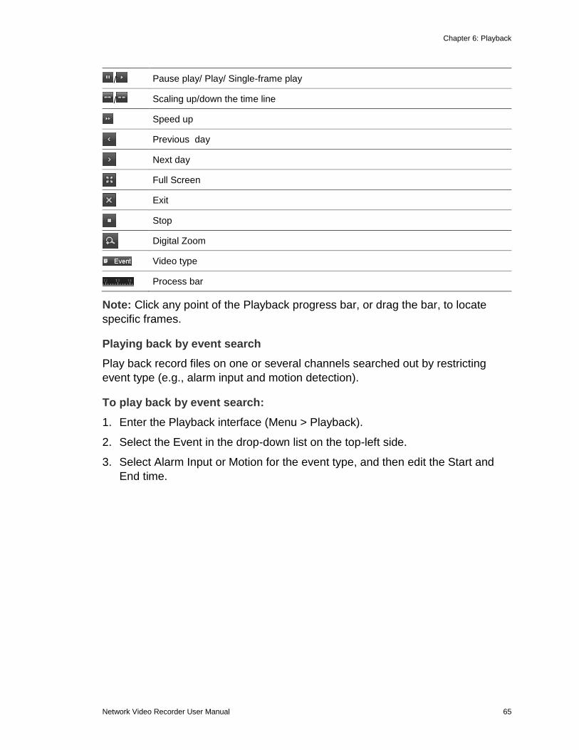
3. Use the toolbar at the bottom part of the Playback interface to control play, as
shown in Figure 26.
Figure 26: Playback by time toolbar
Note: The indicates the start/end time of the record.
Table 19: Playback by time icons
Icons Description
/ Audio on/ Mute
/ Start/Stop clipping
30s forward
30s reverse
Capture frame
Lock video
Add default tag
Add customized tag
Tag management
Speed down
/ Pause reverse play/ Reverse play/ Single-frame reverse play
Chapter 6: Playback
Network Video Recorder User Manual 65
/ Pause play/ Play/ Single-frame play
/ Scaling up/down the time line
Speed up
Previous day
Next day
Full Screen
Exit
Stop
Digital Zoom
Video type
Process bar
Note: Click any point of the Playback progress bar, or drag the bar, to locate
specific frames.
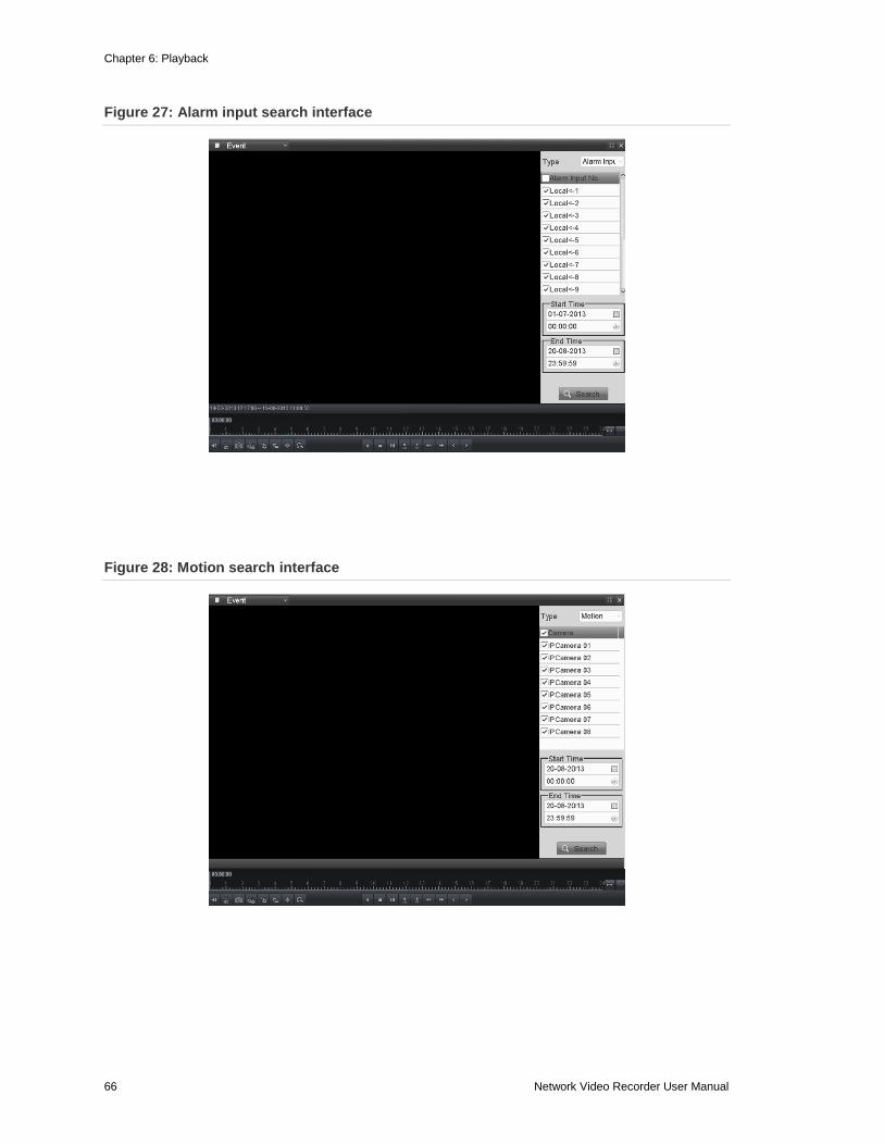
Playing back by event search
Play back record files on one or several channels searched out by restricting
event type (e.g., alarm input and motion detection).
To play back by event search:
1. Enter the Playback interface (Menu > Playback).
2. Select the Event in the drop-down list on the top-left side.
3. Select Alarm Input or Motion for the event type, and then edit the Start and
End time.
Chapter 6: Playback
66 Network Video Recorder User Manual
Figure 27: Alarm input search interface
Figure 28: Motion search interface
Chapter 6: Playback
Network Video Recorder User Manual 67
4. Click the Search button to get the search result information. Refer to the right-
side bar for the result.
5. Click button to play back the file.
Note: Pre-play and post-play is configured.
If the event is set to trigger recording for multiple channels, clicking displays the Synch Playback interface. You can select channels to play back synchronously.
Click the Back button to return to the search interface.
6. Use the toolbar at the bottom of the Playback interface for controls.
Chapter 6: Playback
68 Network Video Recorder User Manual
Figure 29: Playback by event toolbar
Table 20: Playback by event icons
Icons Description
/ Audio on/ Mute
/ Start/Stop clipping
30s forward
30s reverse
Capture frame
Lock video
Add default tag
Add customized tag
Tag management
Speed down
/ Pause reverse play/ Reverse play/ Single-frame reverse play
/ Pause play/ Play/ Single-frame play
/ Scaling up/down the time line
Speed up
Previous day
Next day
Full Screen
Exit
Stop
Digital Zoom
Video type
Process bar
Note: Use the mouse to click any point of the Playback progress, or drag the
progress bar, to locate specific frames.
Chapter 6: Playback
Network Video Recorder User Manual 69
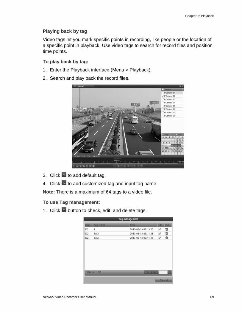
Playing back by tag
Video tags let you mark specific points in recording, like people or the location of
a specific point in playback. Use video tags to search for record files and position
time points.
To play back by tag:
1. Enter the Playback interface (Menu > Playback).
2. Search and play back the record files.
3. Click to add default tag.
4. Click to add customized tag and input tag name.
Note: There is a maximum of 64 tags to a video file.
To use Tag management:
1. Click button to check, edit, and delete tags.
Chapter 6: Playback
70 Network Video Recorder User Manual
2. Select the tag from the drop-down list in the Playback interface.
3. Choose channels, edit start time and end time, and then click Search to enter
the Search Result interface.
Note: You can enter a keyword in the Keyword textbox to search the tag on
your command.
4. Click to play back the file.
You can click the Back button to return to the search interface.
Note: You can configure pre-play and post-play.
Chapter 6: Playback
Network Video Recorder User Manual 71
Figure 30: Playback by tag toolbar
Table 21: Playback by tag icons
Icons Description
/ Audio on/ Mute
/ Start/Stop clipping
30s forward
30s reverse
Add default tag (not supported)
Capture frame
Lock video
Add customized tag (not supported)
Tag management
Speed down
/ Pause reverse play/ Reverse play/ Single-frame reverse play
/ Pause play/ Play/ Single-frame play
/ Scaling up/down the time line
Speed up
Previous day
Next day
Full Screen
Exit
Stop
Digital Zoom
Video type
Process bar
Note: Use the mouse to click any point of the Playback progress bar, or drag the progress bar to locate special frames.
Chapter 6: Playback
72 Network Video Recorder User Manual
Playing back by system logs
Play back record files associated with channels after searching the system logs.
To play back by system logs:
1. Enter the Log Information interface (Menu > Maintenance > Log Information).
2. Click the Log Search tab to enter Playback by System Logs.
3. Set search time and type and click Search button.
4. Choose a log with record file and click to enter the Playback interface.
Note: If there is no record file at the time point of the log, the No result found
dialog box displays.
Chapter 6: Playback
Network Video Recorder User Manual 73
5. Use the toolbar in the bottom part of the Playback interface to control playing
process.
Playing back external file
Follow the steps to search for and play files in an external device.
To play back external files:
1. Enter the Tag Search interface (Menu > Playback).
2. On the top-left, select the file from the drop-down menu. Click the Refresh button to refresh the file list.
3. Select and click to play the file.
Chapter 6: Playback
74 Network Video Recorder User Manual
Auxiliary functions of playback
Playing back frame by frame
Play video files frame by frame to check the image details of the video when
abnormal events occur.
To play back frame by frame using a mouse:
1. Go to the Playback interface.
2. When you choose playback of the record file, click until the speed changes
to a single frame. One click on the Playback screen represents plays one
frame.
3. When you choose reverse playback of the record file, click until the speed
changes to a single frame. One click on the Playback screen represents
reverse playback of one frame. You can also use the button in the toolbar.
To play back frame by frame using the front panel:
1. Hold and rotate the outer ring on the Jog Shuttle counter clockwise
(for 16 and 32-Channel only), or click to set the speed to Single frame.
One click on button, one click on the playback screen, or Enter button on
the front panel represents playback or reverse playback of one frame.
Digital zoom
To use digital zoom:
1. Click on the playback control bar to enter the Digital Zoom interface.
2. Using the mouse, draw a rectangle. The image is enlarged up to 16 times.
3. Right-click the image to exit the Digital Zoom interface.
Chapter 6: Playback
Network Video Recorder User Manual 75
Reverse playback of multi-channel
Simultaneous playback is supported for multi-channel. Up to 16-channel (with
1280x720 resolution) simultaneous reverse playback is supported; up to 4-
channel (with 1920x1080 resolution) simultaneous reverse playback is supported
and up to 1-channel (with 2560x1920 resolution) reverse playback is supported.
To reverse playback of multiple channels:
1. Enter the Playback interface (Menu > Playback).
2. Select more than one check box to select multiple channels, and then click to
select a date on the calendar.
3. Click to play the files in reverse. -
Picture playback
Search and view captured pictures stored in HDD.
To use picture playback:
1. Enter the Playback interface (Menu > Playback).
2. Select the picture in the drop-down list on the top-left side.
Chapter 6: Playback
76 Network Video Recorder User Manual
3. Choose channels, edit start time and end time, and then click Search.
4. Choose the file you want to view and click .
Click the Back button to return to the search interface.
5. Use the toolbar in the bottom part of Playback interface to control play.
Chapter 6: Playback
Network Video Recorder User Manual 77
Figure 31: Picture playback toolbar
Table 22: Picture playback toolbar icons
Button Description
Play reverse
Play
Previous picture
Next picture
78 Network Video Recorder User Manual
Chapter 7 Backup
Backing up recorded files
Backing up by normal video search
You can back up record files to various devices, such as USB devices (USB flash
drives, USB HDDs, USB writer), SATA writer, and e-SATA HDD.
To backup using USB flash drives and USB HDDs:
1. Enter Export interface.
Menu > Export > Normal
2. Set search condition and click Search to enter the search result interface.
3. Choose the record file in the Export interface, and then click to check it.
Note: The size of the selected files displays in the lower-left corner of the
window.
Chapter 7: Backup
Network Video Recorder User Manual 79
4. Click Export and start backup.
Note: If the inserted USB device is not recognized, do the following.
Click the Refresh button.
Reconnect device.
Check the vendor’s compatibility.
You can format USB flash drives or USB HDDs via the device.
5. Stay in the Exporting interface until all record files are exported. When
complete, the dialog displays “Export finished.”
Note: The file format is MP4.
Chapter 7: Backup
80 Network Video Recorder User Manual
6. Check the results by selecting the record file in Export interface, and then
click .
To backup using USB and SATA writers:
1. Enter Export interface.
Menu > Export > Normal
2. Set search condition and click the Search button.
3. Choose the recorded file in the Export interface, and then click .
Note: The size of the selected file is displayed in the lower-left corner.
4. Click Export and start the backup.
Chapter 7: Backup
Network Video Recorder User Manual 81
Note: If the inserted USB writer or SATA writer is not recognized, do the
following.
Click the Refresh button.
Reconnect device.
Check the vendor’s compatibility.
5. Select the file type by clicking the corresponding option icon, and then click
OK to start backup.
6. Stay in the Exporting interface until all record files are exported.
When complete, the Export dialog displays “Export finished.”
Chapter 7: Backup
82 Network Video Recorder User Manual
7. Check the backup results by choosing the record file in the Export interface,
and then click to check it.
To backup using eSATA HDDs
1. Browse to Advanced Settings.
Menu > Record > Advanced
2. Select eSATA and set the usage to Export.
3. Click Yes when prompted.
Note: The usages of eSATA HDD contain Record/Capture and Export.
Changes in usage will take effect after your reboot the device.
4. Access the Export interface.
Menu > Export > Normal
5. Set the search condition, and then click Search button.
6. In the Export interface, click to select and view the record file.
Note: The lower-left corner displays the size of the selected file.
7. Click Export to start the backup.
Chapter 7: Backup
Network Video Recorder User Manual 83
Note: Format the eSATA HDD when using it for the first time. If the HDD is not recognized, do the following.
a. Click the Refresh button.
b. Reconnect the device.
c. Check the vendor’s compatibility.
You can also format the eSATA HDD via the device.
8. Select the file type by clicking its corresponding option icon, and then click OK to start the backup.
9. Stay in the Exporting interface until all record files are exported. When
complete, the dialog box displays “Export finished.”
10. Check the results by choosing the record file in Export interface, and then
clicking to check it.
Chapter 7: Backup
84 Network Video Recorder User Manual
Backing up by event search
Back up event-related record files using USB devices (USB flash drives, USB
HDDs, USB writer), SATA writer or eSATA HDD. Quick Backup and Normal
Backup are supported.
To backup by event search:
1. Enter the Export interface.
Menu > Export > Event
2. Choose Motion from the Event Type list.
Note: Event types contain Alarm Input and Motion. The following example
shows backing up by motion.
3. Select the alarm input number and time.
4. Click Search to enter the Search Result interface.
5. Click Quick Export to export the record files of all channels triggered by the
selected alarm input.
6. Click Details to view detailed information of the record file, such as start time,
end time, file size, etc.
Chapter 7: Backup
Network Video Recorder User Manual 85
7. Click Export to start the backup.
Note: If the inserted USB device is not recognized:
a. Click Refresh.
b. Reconnect the device.
c. Check the vendor’s compatibility.
You can also format USB flash drives or USB HDDs via the device.
8. Stay in the Exporting interface until all record files are exported. When
complete, the dialog displays “Export finished.”
9. Choose the record file in Export interface and click button to check it.
Chapter 7: Backup
86 Network Video Recorder User Manual
Backing up video clips
You can also select video clips to export directly during Playback using USB devices (USB flash drives, USB HDDs, USB writer), SATA writer, or eSATA HDD.
To backup video clips:
1. Enter the Playback interface.
2. During playback, use and in the playback toolbar to start or stop clipping
record files.
3. Use the Quit Playback interface when finishing clipping. You are prompted to
save the clips.
Note: You can select a maximum of thirty clips for each channel.
4. Click Yes to save video clips and enter Export interface.
– or –
Click No to quit and do not save video clips.
Note: If the inserted USB device is not recognized, do the following.
a. Click Refresh.
b. Reconnect the device.
c. Check the vendor’s compatibility.
You can also format USB flash drive or USB HDDs via the device.
Chapter 7: Backup
Network Video Recorder User Manual 87
5. Stay in the Exporting interface until all record files are exported. When complete, the dialog displays “Export finished.”
6. Choose the record file in Export interface and click button to check it.
Backing up pictures Back up pictures using USB devices (USB flash drives, USB HDDs, USB writer),
SATA writer, or eSATA HDD.
To backup pictures:
1. Enter the Export interface.
Menu > Export > Picture
2. Select the channels, image type, start time and end time, and then click
Search to enter the Search Result interface.
Chapter 7: Backup
88 Network Video Recorder User Manual
3. Click the check box for each picture you want to back up, and then click
Export.
Note: The following example shows backing up to a USB flash drive.
4. Click Export to start the backup.
5. Stay in the Exporting interface until all record files are exported. When
complete, the dialog displays “Export finished.”
6. Click OK.
Chapter 7: Backup
Network Video Recorder User Manual 89
Managing backup devices To manage USB flash drives, USB HDDs, and eSATA HDDs.
1. Enter the Search Result interface for the record files.
Menu > Export > Normal
2. Set the search condition, and then click Search to enter Search Result
interface.
Note: You must select at least one camera.
3. Select the record files you want to back up, and then click Export to enter the
Export interface.
Note: You must select at least one record.
4. Click New Folder to create a new folder in the backup device.
5. Select a record file or folder in the backup device, or click the to delete it.
6. Select a record file in the backup device, and then click to play it.
7. Click Format to format the backup device.
Note: If the inserted USB device is not recognized, do the following.
Chapter 7: Backup
90 Network Video Recorder User Manual
a. Click Refresh.
b. Reconnect the device.
c. Check the vendor’s compatibility.
To manage USB writers:
1. Enter Search Result interface of record files.
Menu > Export > Normal
2. Set search condition, and then click Search to enter Search Result interface.
Note: You must select at least one channel.
3. Click Export to enter the Export interface.
Note: You must select at least one record.
Chapter 7: Backup
Network Video Recorder User Manual 91
92 Network Video Recorder User Manual
Chapter 8 Alarm Settings
Setting motion detection alarm
To set a motion detection alarm:
1. Enter the Motion Detection interface for camera management, and then
choose a camera you want to set up motion detection.
Menu > Camera > Motion
2. Set up the detection area and sensitivity by selecting Enable Motion
Detection.
3. Using the mouse, draw a detection area, and then drag the sensitivity bar to
set sensitivity.
4. Click and set alarm response actions.
5. The Trigger Channel tab displays, select one or more channels that will
record and capture, or become full-screen monitoring when the motion alarm
is triggered.
6. Click Apply to save the settings.
Chapter 8: Alarm Settings
Network Video Recorder User Manual 93
7. Set up the arming schedule of the channel by select the Arming Schedule tab.
8. Choose one day of the week and up to eight times for each day.
9. Click Apply to save the settings
Note: Do not repeat or overlap times.
10. Click the Linkage Action tab to set up the alarm response actions of motion
alarm.
11. If you want to set motion detection for another channel, repeat the steps
above, or simply click Copy in the Motion Detection interface to copy the
settings.
Chapter 8: Alarm Settings
94 Network Video Recorder User Manual
Setting sensor alarms Set the handling action of an external sensor alarm.
To set sensor alarms:
1. Enter the Alarm Settings of System Configuration and select an alarm input.
Menu > Configuration > Alarm
2. Select the Alarm Input tab to enter the Alarm Input Settings interface.
3. Check the Enable check box, and then click Settings to set its alarm response
actions.
4. Click the Trigger Channel tab, and then select one or more channels that will
record and capture or become full-screen monitoring when an external alarm
is detected.
5. Click Apply to save the settings.
6. Click the Arming Schedule tab to set the arming schedule.
Chapter 8: Alarm Settings
Network Video Recorder User Manual 95
7. Choose a day of a week and up to eight times for each day, and then click
Apply.
Note: Do not repeat or overlap times.
8. Repeat the above steps to set up arming schedule for other days. You can
also click Copy to copy an arming schedule to other days.
9. Select the Linkage Action tab to set up alarm response actions of alarm input.
10. If necessary, select the PTZ Linking tab and set PTZ linking parameters, and
then click OK.
Note: Ensure the PTZ or speed dome supports PTZ linkage.
One alarm input can trigger the presets, patrol, or pattern of one or more
channels; however, presets, patrols and patterns are exclusive.
11. If you want to set the handling action of another alarm input, repeat the above
steps.
You can also click Copy on the Alarm Input Setup interface, and then check
the check box for the alarm inputs and copy the settings to them.
Chapter 8: Alarm Settings
96 Network Video Recorder User Manual
Detecting video loss alarm Detects the video loss of a channel and take alarm response action(s).
To set detecting for video loss alarms:
1. Enter the Video Loss interface of Camera Management and select a channel
you want to detect.
Menu > Camera > Video Loss
2. Check the Enable Video Loss Alarm check box, and then click to set up
the handling action for video loss.
3. Click the Arming Schedule tab to set the channel’s arming schedule.
4. Choose a day of a week and up to eight times for each day.
5. Click Apply to save the settings.
Note: Do not repeat or overlap times.
Chapter 8: Alarm Settings
Network Video Recorder User Manual 97
6. Click the Linkage Action tab to set up alarm response action of video loss.
7. Click OK to complete the video loss settings for the channel.
Detecting video tampering alarm Alarms trigger when the lens is covered and takes alarm response actions.
To detect video tampering:
1. Enter the Video Tampering interface, and then select a channel.
Menu > Camera > Video Tampering Detection
2. Check the Enable Video Tampering check box.
3. Drag the sensitivity bar to choose a proper sensitivity level.
4. Using the mouse, draw an area to detect video tampering.
5. Click to set the handling action for video tampering.
Chapter 8: Alarm Settings
98 Network Video Recorder User Manual
6. Click the Arming Schedule tab to set the arming schedule for handling
actions.
7. Choose a day of a week and up to eight periods for each day.
8. Click Apply to save the settings.
Note: Do not repeat or overlap times.
9. Click the Linkage Action tab to set up alarm response actions for the video
tampering alarm.
10. Click OK to complete the video tampering settings for the channel.
Chapter 8: Alarm Settings
Network Video Recorder User Manual 99
Handling alarm exceptions The exception settings refer to handling actions of various exceptions, such as:
HDD Full: The HDD is full.
HDD Error: Writing HDD error or unformatted HDD.
Network Disconnected: Disconnected network cable.
IP Conflicted: Duplicated IP address.
Illegal Login: Incorrect user ID or password.
Record/Capture Exception: No space for saving recorded files or captured
images.
Array Exception: Abnormal virtual disks exist under array.
Note: Array Exception is only supported by the 64-Channel NVR.
To set alarm exceptions:
1. Enter the Exception interface of System Configuration and handle various
exceptions.
Menu > Configuration > Exceptions
Setting alarm response actions Alarm response actions activate when an alarm or exception occurs, including
Full Screen Monitoring, Audible Warning (buzzer), Notify Surveillance Center,
Upload Picture to FTP, Trigger Alarm Output, and Send Email.
Chapter 8: Alarm Settings
100 Network Video Recorder User Manual
Full screen monitoring
When an alarm is triggered, the local monitor (VGA, HDMI, or BNC monitor)
displays in full screen
If alarms are triggered simultaneously in several channels, their full-screen
images are switched at a ten second interval (default dwell time). You can set a
different dwell time by going to Menu > Configuration > Live View > General >
Full Screen Monitoring Dwell Time.
Auto-switch terminates once the alarm stops. You are then taken back to the Live
View interface.
Note: You must select the Trigger Channel settings for the channels you want to
make full screen.
Audible warning
This triggers an audible beep when an alarm is detected.
Notify surveillance center
This sends an exception or alarm signal to the remote alarm host when an event
occurs. The alarm host refers to the PC installed with Remote Client.
Note: The alarm signal transmits automatically at detection when a remote alarm
host is configured.
Email linkage
Send an email with alarm information to a user or users when an alarm is
detected.
Trigger alarm output
Trigger an alarm output when an alarm is triggered.
1. Enter the Alarm Output interface.
Menu > Configuration > Alarm > Alarm Output
2. Select an alarm output and set alarm name and dwell time. Click Schedule
button to set the arming schedule of alarm output.
Note: When you select Manually Clear from the Dwell Time list, you can only
clear it by going to Menu > Manual > Alarm.
Chapter 8: Alarm Settings
Network Video Recorder User Manual 101
3. Choose a day of a week and up to eight times for each day.
Note: Do not repeat or overlap times.
4. Repeat the above steps to set an arming schedule for the other days of a
week.
You can also use the Copy button to copy an arming schedule to other days.
5. Click OK to complete the video tampering settings of the alarm output.
You can also copy the above settings to another channel.
Triggering or clearing alarm output manually Sensor alarm is triggered or cleared manually. When you select Manually Clear
from the Dwell Time list, you can only clear the alarm by clicking Clear in the
following interface.
To trigger or clear alarms:
1. Select the alarm output you want to trigger or clear.
Menu > Manual > Alarm
2. Click Trigger/Clear when you want to trigger or clear an alarm output.
3. Click Trigger All when you want to trigger all alarm outputs.
4. Click Clear All when you want to clear all alarm output.
Chapter 8: Alarm Settings
102 Network Video Recorder User Manual
103 Network Video Recorder User Manual
Chapter 9 Network Settings
Configuring general settings You must properly configure network settings before you can operate an NVR
over the network.
To configure general settings:
1. Enter the Network Settings interface (Menu > Configuration > Network).
Through one-touch configuration, you can quickly create the disk array and
virtual disk. By default, the array type is RAID 5.
Steps:
1. Enter the Physical Disk Settings interface (Menu > HDD > RAID > Physical
Disk).
Chapter 10: RAID
120 Network Video Recorder User Manual
2. Click the One-touch Configuration button to enter the One-touch Array
Configuration interface.
Note: As the default array type is RAID 5, at least three HDDs are installed in
your device.
3. Edit the array name in the Array Name field, and then click OK to start
configuring array.
Note: If you install four or more HDDs for one-touch configuration, a hot
spare disk will is set by default. We recommend that you set the hot spare
disk to automatically rebuild the array when the array is abnormal.
4. When the array configuration is complete, click OK to finish the settings.
5. Click the Array tab to view the information of the successfully created array.
Note: By default, one-touch configuration creates an array and a virtual disk.
If the capacity of the array created through one-touch configuration is greater
than 16 TB, two arrays and two virtual disks are created.
Chapter 10: RAID
Network Video Recorder User Manual 121
6. Click the Virtual Disk tab to view the automatically created virtual disk.
After the foreground initialization of the virtual disk is complete, the virtual disk
displays in the HDD Information interface (Menu > HDD > General).
Manually creating array and virtual disk
You can manually create the array of RAID 0, RAID 1, RAID 5 and RAID 10.
Note: In this section, we use RAID 5 as an example describing the manual
configuration of array and virtual disk.
To manually create an array and virtual disk:
1. Enter the Physical Disk Settings interface (Menu > HDD > RAID > Physical
Disk).
2. Click Create to enter the Create Array interface.
Chapter 10: RAID
122 Network Video Recorder User Manual
3. Edit the Array Name; set the RAID Level to RAID 0, RAID 1, RAID 5 or RAID
10; and select the Physical Disk that you want to configure array.
Notes
If you choose RAID 0, at least two HDDs are installed.
If you choose RAID 1, two HDDs are configured for RAID 1.
If you choose RAID 5, at least three HDDs are installed.
If you choose RAID 10, four, six, or eight HDDs are configured for RAID
10.
4. Click OK to create an array.
Note: If the number of HDDs you select is not compatible with the
requirement of the RAID level, the error dialog displays.
5. Click the Array tab to view the successfully created array.
6. Click to select an array, and then click Create Virtual Disk to enter the Create
Virtual Disk interface.
Note: The device supports creating up to eight virtual disks.
Chapter 10: RAID
Network Video Recorder User Manual 123
7. Edit the name of the virtual disk, set the capacity for the virtual disk, and
select the initialization type for the virtual disk.
Notes
You can click the Information of Array Capacity area to set the remaining
capacity of the array for the disk.
It is recommended to create one virtual disk of an array.
At least 100 GB capacity are configured for each virtual disk.
There are three initialization types, Background, Foreground, and Fast.
o Fast (Not Recommended): The fast initialization is quick, only
initializes part of the data of the virtual disk, and cannot detect bad
sectors.
o Foreground (Recommended): By using foreground initialization,
the virtual disk is completely initialized and the bad sector of the
hard disks is detected and repaired. The virtual disk is used only
after the initialization is complete.
o Background: The background initialization can synchronize the
disks, detect, and repair the bad sector of the disks. During the
background initialization, the virtual disk is allowed.
8. Click Apply to save the settings, and then click OK to return to Array Settings
interface.
9. Click the Virtual Disk tab to enter the Virtual Disk interface.
A successfully created virtual disk is listed on the interface.
Chapter 10: RAID
124 Network Video Recorder User Manual
10. Enter the HDD Information interface (Menu > HDD > General) and the virtual
disk displays. For the operation guide of initializing the virtual disk, see
“Initializing HDDs” on page 133.
Note: If you adopt foreground initialization, the virtual disk displays in the
HDD Information interface after the initialization is complete.
After initializing the virtual disk, the status will change from Uninitialized to
Normal.
11. Enter the Physical Disk Settings interface to configure the hot spare disk.
12. Select a disk, and then click to enter the Set Hot Spare interface.
13. Set the hot spare type of the selected HDD to Global Hot Spare or the
specified hot spare for the existing array.
Chapter 10: RAID
Network Video Recorder User Manual 125
Global Hot Spare: It is used as the hot spare for any array created in the
system.
Array Hot Spare: It is used as the hot spare for the specified array only.
(e.g., RAID 5)
14. Click OK to finish the settings.
Note: When the auto-rebuild function is enabled, the hot spare disk is
automatically used to rebuild the array when the virtual disk is in Degraded
status.
Rebuilding array
The working status of array includes Functional, Degraded, and Offline. By
viewing the array status, you can perform immediate and proper maintenance for
the disks to ensure high security and reliability of the data stored in the disk
array.
When there is no disk loss in the array, the working status of array changes to
Functional. When the number of lost disks has exceeded the limit, the working
status of array changes to Offline. In other conditions, the working status is
Degraded. If the virtual disk is in Degraded status, you can restore it to functional
by rebuilding the array.
Automatically rebuilding the array
When the virtual disk is in Degraded status, the device can start rebuilding the
array automatically with the hot spare disk to ensure the high security and
reliability of the data.
Before you start
Enable the Auto-rebuild in the Firmware Settings interface
(Menu > HDD > RAID > Firmware) and ensure the hot spare disk has been
configured.
To automatically rebuild an array:
1. Enter the Array Settings interface (Menu > HDD > RAID > Array).
The status of the array is Disk Loss. If the hot spare disk is configured and
Auto-rebuild function is enabled, the hot spare disk is automatically used for
array rebuilding.
Chapter 10: RAID
126 Network Video Recorder User Manual
2. Enter the Virtual Disk interface to view the rebuilding status of the virtual disk
(Menu > HDD > RAID > Virtual Disk).
Note: If there is no hot spare disk after rebuilding, we recommend installing the
HDD into the device and set is as a hot spare disk. This will ensure high security
and reliability of the array.
Manually rebuilding array
If you do not enable the auto-rebuild in Firmware Settings interface (Menu > HDD
> RAID > Firmware), or if the hot spare disk was not been configured, then you
can rebuild the array manually to restore the array when the virtual disk is in
Degraded status.
To manually rebuild an array:
1. Enter the Array Settings interface (Menu > HDD > RAID > Array).
2. Enter the Virtual Disk interface to check the status of the virtual disk.
In the example below, the virtual disk shows a Degraded status.
3. Click the Array tab to return to the Array Settings interface, and then click
to configure the array rebuild.
Note: At least one available physical disk should exist for rebuilding the array.
Chapter 10: RAID
Network Video Recorder User Manual 127
4. Select the available physical disk, and then click OK to confirm rebuilding the
array.
5. The “Do not unplug the physical disk when it is under rebuilding” dialog
displays. Click OK to start the rebuild.
You can enter the Array Settings interface and the Virtual Disk interface to view
the rebuilding status.
After rebuilding successfully, the array and virtual disk restores to Functional.
Note: We recommend enabling the Auto-rebuild function and setting the hot
spare disk for automatically rebuilding the array.
Repairing a virtual disk
If the disk cannot display in the HDD Information interface, but the virtual disk still
shows in the Array Settings interface, you must repair the virtual disk.
Note: Repair is unavailable if the virtual disk is under foreground initialization.
To repair a virtual disk:
1. Enter the Virtual Disk interface (Menu > HDD > RAID > Virtual Disk).
2. Click to repair the virtual disk.
3. When the dialog notifies you that the repair was successful, click OK to finish.
Chapter 10: RAID
128 Network Video Recorder User Manual
The disk shows in the HDD Information interface (Menu > HDD > General).
Deleting the virtual disk and array
Before deleting the array, you must delete the virtual disks that exist under the
array. Deleting an array and virtual disk will delete all data saved on the disk.
Deleting the virtual disk
To delete the virtual disk:
1. Enter the Virtual Disk interface (Menu > HDD > RAID > Virtual Disk).
2. Select a virtual disk, and then click to delete the virtual disk.
3. Click Yes to confirm the virtual disk deletion.
Deleting the array
Before deleting the array, ensure all the virtual disks existing under an array have
been deleted.
To delete the array:
1. Enter the Array Settings interface (Menu > HDD > RAID > Array).
Chapter 10: RAID
Network Video Recorder User Manual 129
2. Select an array, and then click to delete the array.
3. Click Yes to confirm the array deletion.
Migrating and extending
When the remaining storage space is lower than what is needed, use array
migration and extend it to enlarge the capacity of the virtual disk.
Before you start
At least one available physical disk should exist for the array migration.
To migrate and extend storage:
1. Enter the Physical Disk Settings interface (Menu > HDD > RAID > Physical
Disk).
2. Click the Array tab to enter the Array Settings interface.
3. Select the array to migrate, and then click to enter the Migrate Array
interface.
Chapter 10: RAID
130 Network Video Recorder User Manual
Notes
Only migrating from RAID 5 to RAID 5 is supported by the device.
If there is no virtual disk existing under the array, the array migration is not
done.
If the virtual disk of the array is under initialization, the array migration is
not done.
4. Select the available physical disks, and then click OK to confirm the settings.
5. When prompted, click OK to start migration.
Enter the Array Settings interface (Menu > HDD > RAID > Array) and Virtual
Disk interface (Menu > HDD > RAID > Virtual) to check the process of the
migration.
Figure 37: Array interface
Figure 38: Virtual Disk interface
6. When the migration process finishes, reboot the device to enable the new
settings.
Chapter 10: RAID
Network Video Recorder User Manual 131
7. After rebooting, enter the HDD Information interface, select an expandable
virtual disk, and then click Expand to expand the virtual disk’s capacity.
8. Click OK to start expanding.
9. When prompted, click OK to finish the settings.
After RAID migration and capacity expansion, the expanded capacity for each
virtual disk is calculated by the following formula: Expanded VD capacity=
(Original VD Capacity / Original Array Capacity) * Newly Added Capacity of Hard
Disk.
Example
The capacity of the original array is 2 TB and two virtual disks exist under this
array, VD1 (100 GB) and VD2 (200 GB). If you migrate the array with a 1 TB
HDD, then after migration and expanding, the expanded VD1 capacity is 50 GB
(50 GB = (100 GB/ 2 TB)*1TB) and the expanded VD2 capacity is 100 GB
(100 GB = (200 GB/ 2T B)*1 TB).
Upgrading firmware
You can view the information of the firmware and upgrade the firmware by local
backup device or remote FTP server.
Chapter 10: RAID
132 Network Video Recorder User Manual
To upgrade the firmware:
1. Enter the Firmware interface to check the information of the firmware,
including the version, maximum physical disk quantity, maximum array
quantity, auto-rebuild status, etc.
2. Click Upgrade to upgrade the firmware.
Local and FTP upgrades are available.
Note: contact the dealer immediately if the device does not work properly after upgrading.
Network Video Recorder User Manual 133
Chapter 11 HDD Management
Initializing HDDs Initialize the hard disk drive (HDD) before using it with your NVR.
Notes
When the NVR starts, a dialog displays if any uninitialized HDD exists.
Initializing the HDD will erase all existing data on it.
Figure 39: Dialog of uninitialized HDD
Click Yes to initialize it immediately, or you can perform the following steps to
initialize the HDD.
To initialize HDD:
1. Enter the HDD Information interface (Menu > HDD > General).
2. Select the HDD for initialization.
3. Click the Init button.
Chapter 11: HDD Management
134 Network Video Recorder User Manual
4. Select the OK button to start initialization.
5. After the HDD has initialized, the status is changed from Uninitialized to
Normal.
Managing Network HDD
You can add the allocated NAS or disk of the IP SAN to NVR, and use it as a
network HDD.
To manage the HDD network:
1. Enter the HDD Information interface (Menu > HDD > General).
2. Click Add to enter the Add NetHDD interface.
3. Add the allocated NetHDD.
Chapter 11: HDD Management
Network Video Recorder User Manual 135
4. Set the type to NAS or IP SAN.
5. Configure the NAS or IP SAN settings.
To add NAS disk:
1. Enter the NetHDD IP address in the text field.
2. Click the Search button to search the available NAS disks.
3. Select the NAS disk from the list shown below.
— or —
Manually enter the directory in the NetHDD Directory field.
4. Click OK to add the configured NAS disk.
Note: Up to eight NAS disks is added.
To add IP SAN:
1. Enter the NetHDD IP address in the text field.
2. Click the Search button to search the available IP SAN disks.
3. Select the IP SAN disk from the list shown below.
4. Click OK to add the selected IP SAN disk.
Note: One IP SAN disk is added.
Chapter 11: HDD Management
136 Network Video Recorder User Manual
5. After successfully adding the NAS or IP SAN disk, return to the HDD
Information menu. The added NetHDD displays in the list.
Note: If the added NetHDD is uninitialized, select it and click the Init button
for initialization.
Managing eSATA
When there is an external eSATA device connected to NVR, you can configure
eSATA t Record/Capture or Export, and you can manage the eSATA in the NVR.
To manage eSATA:
1. Enter the Advanced Record Settings interface (Menu > Record > Advanced).
2. Select the eSATA type to Export or Record/Capture from the drop-down list of
eSATA.
Export: use the eSATA for backup.
Record/Capture: use the eSATA for record/capture. Refer to the following
steps for operating instructions.
To use eSATA to record and capture:
1. Select Record/Capture, and then enter the HDD Information interface
(Menu > HDD > General).
Chapter 11: HDD Management
Network Video Recorder User Manual 137
2. Edit the property of the selected eSATA, or initialization is required.
Note: When used for Record/Capture, two storage modes is configured for the
eSATA. Refer to “Managing the HDD group” on page 137 and “Configuring
Quota mode” on page 139 for details.
Managing the HDD group
Setting HDD groups
Multiple HDDs is managed in groups. Video from specified channels is recorded
to a particular HDD group through HDD settings.
To manage HDD groups:
1. Enter the Storage Mode interface (Menu > HDD > Advanced).
2. Set the Mode to Group.
3. Click Apply. The Attention dialog displays.
4. Click Yes to reboot the device and activate the changes.
5. After the reboot completes, enter the HDD Information interface
(Menu > HDD > General).
6. Select HDD from the list and click to enter the Local HDD Settings
interface.
Chapter 11: HDD Management
138 Network Video Recorder User Manual
7. Select the Group number for the current HDD.
Note: The default group number for each HDD is 1.
8. Click OK to confirm the settings. The Attention dialog displays.
9. Click Yes to finish the settings.
Setting the HDD property
The HDD property is set to redundancy, read-only, or read/write (R/W). Before
setting the HDD property, set the storage mode to Group.
An HDD is set to read-only to prevent important recorded files from being
overwritten when the HDD becomes full in overwrite recording mode.
When the HDD property is set for redundancy, the video is recorded on both the
redundancy HDD and the R/W HDD simultaneously. This ensures high security
and reliable video data.
To set HDD properties:
1. Enter the HDD Information interface (Menu > HDD > General).
2. Select HDD from the list, and then click to enter the Local HDD Settings
interface.
Chapter 11: HDD Management
Network Video Recorder User Manual 139
3. Set the HDD property to R/W, Read-only, or Redundancy.
4. Click OK to save the settings and exit the interface.
In the HDD Information menu, the HDD property displays in the HDD Information
menu.
Note: At least two hard disks are installed on your NVR in order to set the HDD
to Redundancy, and one HDD with the R/W property.
Configuring Quota mode
Each camera is configured with an allocated quota for the storage of recorded
files or captured pictures.
To configure Quota mode:
1. Enter the Storage Mode interface (Menu > HDD > Advanced).
2. Set the mode to Quota.
Note: Reboot the NVR to enable the changes to take effect.
3. Select a camera to configure quota.
4. Enter the storage capacity in the text fields of Max. Record Capacity (GB) and
Max. Picture Capacity (GB).
Chapter 11: HDD Management
140 Network Video Recorder User Manual
5. You can copy the quota settings of the current camera to other cameras if
required. Click the Copy button to enter the Copy Camera menu.
6. Select the camera(s) to configure with the same quota settings. You can also
check the check box of IP Camera to select all cameras.
7. Click OK to finish the Copy settings and return to the Storage Mode interface.
8. Click Apply to apply the settings.
Note: If the quota capacity is set to “0,” then all cameras will use the total
capacity of HDD for record and picture capture.
Checking HDD status
You can check the status of the HDDs installed on the NVRs so that you can
take immediate action in case of an HDD failure.
To check the status on the General tab:
1. Enter the HDD Information interface (Menu > HDD > General).
2. Check the status of each HDD displayed in the list.
Chapter 11: HDD Management
Network Video Recorder User Manual 141
Note: If the status is Normal or Sleeping, then the HDD is working normally. If
the status is Uninitialized or Abnormal, initialize the HDD before use. If the HDD
initialization failed, replace it with a new one.
To check the status on the System Info tab:
1. Enter the System Information interface (Menu > Maintenance > System Info).
2. Click the HDD tab to view the status of each HDD displayed on the list.
HDD detection
Note: The 64 Channel NVR does not support this function.
The device provides the HDD detection function such as adopting S.M.A.R.T.
and the Bad Sector Detection technique. The S.M.A.R.T. (Self-Monitoring,
Analysis and Reporting Technology) is a monitoring system for HDD. It detects
and reports on various indicators of reliability in the hopes of anticipating failures.
S.M.A.R.T. settings
To set S.M.A.R.T.:
1. Enter the S.M.A.R.T. Settings interface (Menu > Maintenance > HDD Detect).
2. Select the HDD to view its S.M.A.R.T information list.
Chapter 11: HDD Management
142 Network Video Recorder User Manual
S.M.A.R.T. related information is shown on the interface. You can choose the
self-test types as Short Test, Expanded Test or the Conveyance Test.
3. Click Start to start the S.M.A.R.T. HDD self-evaluation.
Note: If you want to use the HDD even when S.M.A.R.T. checking failed, you
can click the Continue to use the disk when self-evaluation is failed check box.
Bad sector detection
To detect a bad sector:
1. Click the Bad Sector Detection tab.
2. Select the HDD number in the drop-down list you want to configure, and then choose All Detection or Key Area Detection as the detection type.
3. Click the Detect button to start detection.
Chapter 11: HDD Management
Network Video Recorder User Manual 143
4. Click Error to see the detailed damage information. You can click to pause,
resume, or cancel the detection.
Configuring HDD error alarms
You can configure the HDD error alarms when the HDD status is Uninitialized or
Abnormal.
To configure HDD error alarms:
1. Enter the Exception interface (Menu > Configuration > Exceptions)
2. From the Exception Type list, select HDD Error.
3. Click the check boxes to select the HDD error alarm types.
You can choose from Audible Warning, Notify Surveillance Center, Send
Email and Trigger Alarm Output.
4. Select the alarm output for the Trigger Alarm Output.
5. Click the Apply button to save the settings.
Network Video Recorder User Manual 144
Chapter 12 Camera Settings
Configuring OSD settings You can configure the OSD (On-screen Display) settings for the camera,
including date, time, and camera name.
To configure OSD settings:
1. Enter the OSD Configuration interface (Menu > Camera > OSD).
2. Select the camera to configure OSD settings.
3. Enter the camera’s name in the Camera Name field.
4. Click the Display Name, Display Date, and Display Week check boxes to
select those items.
5. Select the date, time, and mode from the Date Format, Time Format, and
Display Mode drop-down lists.
6. Use the mouse to click and drag the text frame in the Preview window to
adjust the OSD position.
7. Click Apply to apply the settings.
Chapter 12: Camera Settings
Network Video Recorder User Manual 145
Configuring privacy mask
You can configure four-sided privacy mask zones that are not viewed by the operator. The privacy mask prevents the masked surveillance areas from being viewed or recorded.
Note: There are only four configurable privacy mask.
To configure a privacy mask:
1. Enter the Privacy Mask Settings interface (Menu > Camera > Privacy Mask).
2. Select the camera to set privacy mask.
3. Click the Enable Privacy Mask check box to enable this feature.
4. Use the mouse to draw a zone on the window. The zones are marked with
different frame colors.
Note: You can clear a privacy mask zone by clicking its corresponding button.
– or –
Click Clear All to clear all zones.
5. Click Apply to save the settings.
Chapter 12: Camera Settings
146 Network Video Recorder User Manual
Configuring video parameters
To configure video parameters:
1. Enter the Image Settings interface (Menu > Camera > Image).
2. Select the camera to set its image parameters.
3. You can click the arrow to change the value of each parameter.
4. Click Apply to save the settings.
147 Network Video Recorder User Manual
Chapter 13 NVR Management and Maintenance
Viewing system information Using the System Information interface, you can view the device, camera, record,
alarm, network, and HDD information.
To view device information:
1. Enter the System Information interface (Menu > Maintenance > System Info).
2. Click the Device Info tab to view the device name, model, serial number,
firmware version, and encode version.
To view camera information:
1. Enter the System Information interface (Menu > Maintenance > System Info).
2. Click the Camera tab to enter the Camera Information menu to view the
status of each camera.
Chapter 13: NVR Management and Maintenance
148 Network Video Recorder User Manual
To view record information:
1. Enter the System Information interface (Menu > Maintenance > System Info).
2. Click the Record tab to view the recording status encoding parameters of each camera.
To view alarm information:
1. Enter the System Information interface (Menu > Maintenance > System Info).
2. Click the Alarm tab to enter the menu and view the alarm information.
To view network information:
1. Enter the System Information interface (Menu > Maintenance > System Info).
2. Click the Network tab to view the network information.
Chapter 13: NVR Management and Maintenance
Network Video Recorder User Manual 149
To view HDD information:
1. Enter the System Information interface (Menu > Maintenance > System Info).
2. Click the HDD tab to enter the HDD Information menu, and then view the
HDD status, free space, and property.
Searching and export log files
The operation, alarm, exception and information of the NVR is stored in log files,
which you is view and export at any time.
To search and export log files:
1. Enter the Log Search interface (Menu > Maintenance > Log Information).
2. Set the log search conditions to refine your search, including the Start Time,
End Time, Major Type, and Minor Type.
3. Click the Search button to start searching the log files.
The matched log files display in a list, as shown below.
Chapter 13: NVR Management and Maintenance
150 Network Video Recorder User Manual
Note: Up to 2,000 log files is displayed each time.
4. You can click of each log or double-click it to view its detailed information. And you can also click to view the related video files if available.
5. To export the log files, click the Export button to enter the Export menu.
6. Select the backup device from the Device Name drop-down list.
Chapter 13: NVR Management and Maintenance
Network Video Recorder User Manual 151
7. Click the Export to export the log files to the selected backup device.
8. Click the New Folder button to create a new folder in the backup device.
– or –
Click the Format button to format the backup device before log export.
Notes
Connect the backup device to NVR before operating log export.
The log files exported to the backup device are named by exporting time – for
example, 20110514124841logBack.txt.
To export all the log files:
1. Enter the Log Information interface (Menu > Maintenance > Log Information >
Log Export).
2. Click the Log Export tab.
3. Click the HDD check box.
4. Click the Export button to export all of the log files stored in the HDD.
Importing and exporting configuration files
The configuration files of the NVR is exported to a local device for backup; and
the configuration files of one NVR is imported to multiple NVR devices if they are
configured with the same parameters.
Chapter 13: NVR Management and Maintenance
152 Network Video Recorder User Manual
To import and export configuration files:
1. Enter the Import/Export Configuration File interface (Menu > Maintenance >
Import/Export).
2. Click the Export button to export the configuration files to the selected local
backup device.
3. To import a configuration file, select the file from the selected backup device
and click Import. After the import process is completed, reboot the NVR.
Note: When the import finishes, the device reboots automatically.
Upgrading the system
You can upgrade the firmware on your NVR from a local backup device, or a
remote FTP server.
To upgrade from a local backup device:
1. Connect your NVR to the local backup device where the update firmware file
is located.
2. Enter the Upgrade interface (Menu > Maintenance > Upgrade).
3. Click the Local Upgrade tab.
Chapter 13: NVR Management and Maintenance
Network Video Recorder User Manual 153
4. Select the update file from the backup device.
5. Click the Upgrade button to start upgrading.
6. After upgrading is complete, reboot the NVR to activate the new firmware.
Configure the PC (running FTP server) and NVR on the same LAN. Run the
third-party TFTP software on the PC and copy the firmware into the root directory
of the TFTP.
To upgrade via FTP:
1. Enter the Upgrade interface (Menu > Maintenance > Upgrade)
2. Click the FTP tab to enter the local upgrade interface.
3. Enter the FTP server address in the text field.
4. Click Upgrade to start upgrading.
5. After the upgrade completes, reboot the NVR to activate the new firmware.
Chapter 13: NVR Management and Maintenance
154 Network Video Recorder User Manual
Restoring default settings
To restore default settings:
1. Enter the Default interface (Menu > Maintenance > Default).
2. Click OK to restore the default settings.
Note: Except for the network parameters (including IP address, subnet mask,
gateway, MTU, NIC working mode, default route and server port), all other device
parameters are restored to the factory default settings.
Network Video Recorder User Manual 155
Chapter 14 Other Settings
Understanding camera capacity in an NVR
When setting up your NVR and cameras, you may notice that some of the
camera images may not display in Live View. This most often occurs when you
are displaying images in 1+5 mode or 1+7 mode, because the total bit rate for all
cameras is exceeding the NVR’s capacity. The actual capacity depends on the
total bit rate from all the cameras. However, it is good practice to allow some
headroom for machine operations, such as remote streaming.
NVR model Capacity
4-channel 20 Mb
8-channel 40 Mb
16-channel 80 Mb
32-channel 160 Mb
64-channel 160 Mb
To fully understand NVR capacity, it is necessary to understand the concepts of
streaming video, resolution, quality, and bit rate. Streaming video is content sent
in a compressed form over a network and processed in real time.
Streaming video types
• Main Stream: the high quality video that is recorded and streamed.
• Sub Stream: never recorded; intended for streaming only. Default is
704 × 480, 584 Kbps at 8 fps.
• Is video alone, or video and audio compressed together. Audio requires very
little bandwidth.
The combination of the main stream and sub streams makes up the total bit rate
of each camera. This is expressed in Kbps (kilobits per second) or Mbps
(megabits per second).
Chapter 14: Other Settings
156 Network Video Recorder User Manual
Bit rate is determined by the selected resolution (1280 × 720, 1920 × 1080,
2560 × 1920, etc.), frame rate (frames per second), and video quality (the
amount of compression being applied to each camera).
Example
32 channels of 720P cameras at 15 fps with good image quality will have
32 x (1536 + 512) = 65536 Kbps (about 66Mbps), so the 32-channel NVR can
support them.
Each channel can support a different camera, as long as they do not exceed the
total bit rate limit. It is entirely possible to mix 5 MP cameras with 4CIF IP
cameras, etc. Generally, 5 MP at 30 fps requires around 20 Mbps for best
quality. A 4-channel NVR is currently limited to 16 Mbps.
Adjusting settings
Know NVR’s capacity and make adjustments, if necessary. Adjust the bit rate by
lowering the resolution, frame rate, or video quality setting.
To adjust the setting:
1. Enter the Live View settings interface.
2. Adjust the Resolution, Frame Rate, and Video Quality settings.
Configuring RS-232 serial ports
The RS-232 port is used in two ways:
Parameters Configuration: Connect a PC to the NVR through the PC serial port.
Configure device parameters using software such as HyperTerminal. Set the
serial port parameters to match the NVR’s when connecting with the PC serial
port.
Transparent Channel: Connect a serial device directly to the NVR. The PC will
control the serial device remotely through the network and the protocol of that
serial device.
Chapter 14: Other Settings
Network Video Recorder User Manual 157
To configure the RS-232 settings:
1. Enter the RS-232 Settings interface (Menu > Configuration > RS-232).
2. Configure RS-232 parameters, including baud rate, data bit, stop bit, parity,
flow control, and usage.
3. Click the Apply button to save the settings.
Configuring general settings
You can configure the BNC output standard, VGA output resolution, mouse
pointer speed through the Menu > Configuration > General interface.
To configure general settings:
1. Enter the General Settings interface (Menu > Configuration > General).
2. Select the General tab.
3. Configure the following settings:
Language: The language used is English.
CVBS Output Standard: Set the CVBS output standard to NTSC or PAL to
match the video input standard.
VGA Resolution: Set the VGA output resolution to match the monitor screen.
HDMI Resolution: Sett the HDMI resolution to match the monitor screen.
Time Zone: Set the time zone.
Date Format: Set the date format.
Chapter 14: Other Settings
158 Network Video Recorder User Manual
System Date: Set the system date.
System Time: Set the system time.
Mouse Pointer Speed: Set the speed of mouse pointer; four levels are
configurable.
Enable Wizard: Enable/disable the Wizard when the device starts up.
Enable Password: Enable/disable the use of the login password.
4. Click the Apply button to save the settings.
Configuring DST settings
To configure DTS settings:
1. Enter the General Settings interface (Menu > Configuration > General).
2. Choose DST Settings tab.
3. Check the Auto DST Adjustment check box.
- or -
Check the Enable DST check box, and then enter the date for the DST
period.
Configuring more settings for device parameters
To configure more settings:
1. Enter the General Settings interface (Menu > Configuration > General).
2. Click the More Settings tab to enter the More Settings interface.
3. Configure the following settings:
Device Name: Edit the name of NVR.
Chapter 14: Other Settings
Network Video Recorder User Manual 159
Device No.: Edit the serial number of NVR. The device number is set in the
range from 1 to 255. The default number is 255. It is used for the remote and
keyboard control.
CVBS Output Brightness: Adjust the video output brightness.
Auto Logout: Set timeout time for menu inactivity. For example, when the
timeout time is set to five Minutes, the system will exit from the current
operation menu to the Live View screen after 5 minutes of menu inactivity.
Menu Output Mode: You can choose the menu display on different video
output. There are auto, HDMI, VGA and Main CVBS selectable.
4. Click the Apply button to save the settings.
Adding an NVR using the web interface
You can add MVRs using the web interface for the 16 channel, 32 channel, and
64 channel NVR only.
To add a camera using the web interface:
1. Enter the Camera Management interface (Menu > Configuration > Camera
Management > IP Camera).
Chapter 14: Other Settings
160 Network Video Recorder User Manual
2. Configure the IP cameras parameters.
IP Camera Address: The camera’s IP address
Protocol: Protocol being used
Management Port: Port number being used to manage the NVR
Channel No.: Channel being used by the NVR
User Name: User name to log into the NVR
Password: Password to log into the NVR
Confirm: Password confirmation
Adding Method: The method used to add the IP Camera
3. Click OK to add the camera.
Managing user accounts
There is a default account in the NVR. The Administrator user name is
“clareadmin” and the password is “secure7”. The Administrator has the
permission to add and delete users and configure user parameters.
Adding a user
To add a user:
1. Enter the User Management interface (Menu > Configuration > User).
Chapter 14: Other Settings
Network Video Recorder User Manual 161
2. Click the Add button to enter the Add User interface.
3. Enter the information for the new user, including User Name, Password, Level
and User’s MAC Address.
Level: Set the user level to Operator or Guest. Different user levels have
different operating permission.
Operator: The Operator user level has permission for Two-way Audio in
Remote Configuration and all operating permission in Camera
Configuration by default.
Guest: The Guest user does not have permission to use Two-way Audio
in Remote Configuration and only has the local/remote playback in the
Camera Configuration by default.
User’s MAC Address: The MAC address of the remote PC that logs onto the
NVR. If it is configured and enabled, it only allows the remote user with this
MAC address to access the NVR.
4. Click OK to save the settings and go back to the User Management interface.
The added new user displays on the list.
5. Select the user from the list and then click to enter the Permission settings
interface.
Chapter 14: Other Settings
162 Network Video Recorder User Manual
6. Set the operating permission for the Local Configuration, Remote
Configuration, and Camera Configuration for the user.
Local configuration
Local Log Search: Searching and viewing logs and system information of
NVR.
Local Parameters Settings: Configuring parameters, restoring factory
default parameters and importing/exporting configuration files.
Local Camera Management: The adding, deleting and editing of IP
cameras.
Local Advanced Operation: Operating HDD management (initializing HDD,
setting HDD property), upgrading system firmware, clearing I/O alarm
output.
Local Shutdown Reboot: Shutting down or rebooting the NVR.
Remote configuration
Remote Log Search: Remotely viewing logs that are saved on the NVR.