1. NETWORKING CONCEPTS 1.1 Learning objectives To know about uses, applications, disadvantages of network To elaborate various types of network To elaborate various types of topologies Discuss switching techniques 1.2 Definition A computer network is defined as the interconnection of two or more computers. It is done to enable the computers to communicate and share available resources. 1.3 Applications Sharing of resources such as printers Sharing of expensive software's and database Communication from one computer to another computer Exchange of data and information among users via network Sharing of information over geographically wide areas. 1.4 Uses of computer networks sharing information sharing of hardware and software Reduced cost Improved security Centralized software managements Electronic mail Flexible access Increased speed 1.5 Components of computer networks Two or more computers Cables as links between the computers A network interfacing card(NIC) on each computer Switches Software called operating system(OS) 1.6 Disadvantages of computer networks High cost of installation Requires time for administration Failure of server
Transcript
1. NETWORKING CONCEPTS
1.1 Learning objectives
To know about uses, applications, disadvantages of network
To elaborate various types of network
To elaborate various types of topologies
Discuss switching techniques
1.2 Definition
A computer network is defined as the interconnection of two or more computers. It is done to enable the computers to communicate and share available resources.
1.3 Applications
Sharing of resources such as printers
Sharing of expensive software's and database
Communication from one computer to another computer Exchange of data and information among users via network
Sharing of information over geographically wide areas.
1.4 Uses of computer networks
sharing information
sharing of hardware and software
Reduced cost
Improved security
Centralized software managements
Electronic mail
Flexible access
Increased speed
1.5 Components of computer networks
Two or more computers
Cables as links between the computers
A network interfacing card(NIC) on each computer
Switches
Software called operating system(OS)
1.6 Disadvantages of computer networks
High cost of installation
Requires time for administration
Failure of server
1.7 Types of Networks
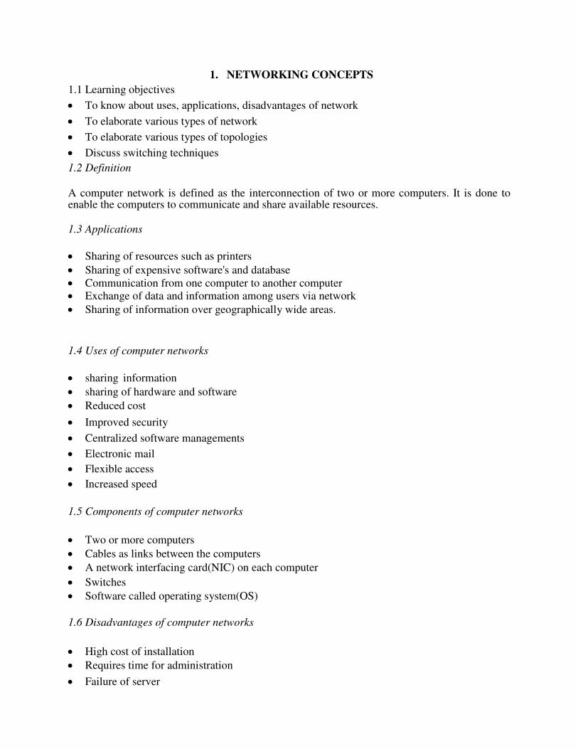
1.7.1 LAN(Local Area Network)
LAN is a network which is designed to operate over a small physical area such as an office, factory or a group of buildings.
LAN’s are easy to design and troubleshoot
Exchange of information and sharing of resources becomes easy because of LAN. In LAN all machines are connected to a single cable. Different types of topologies such as star, tree, bus, ring, etc Can be used
It is usually a privately owned network.
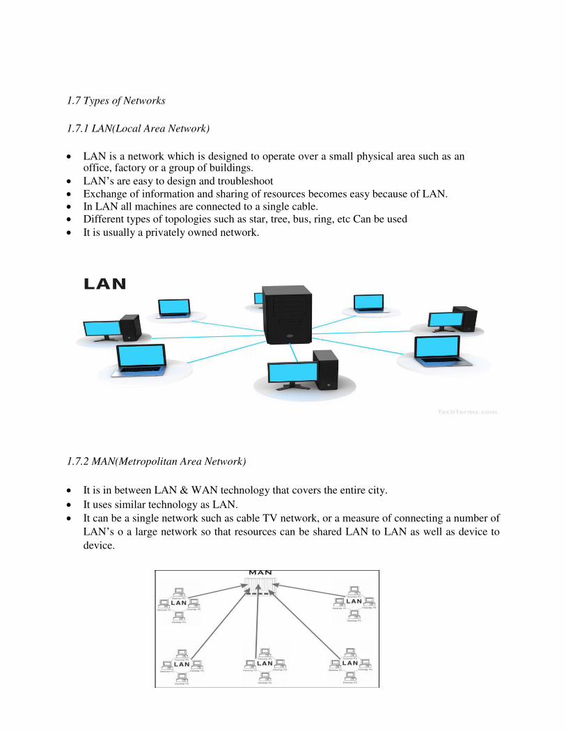
1.7.2 MAN(Metropolitan Area Network)
It is in between LAN & WAN technology that covers the entire city.
It uses similar technology as LAN.
It can be a single network such as cable TV network, or a measure of connecting a number of
LAN’s o a large network so that resources can be shared LAN to LAN as well as device to
device.
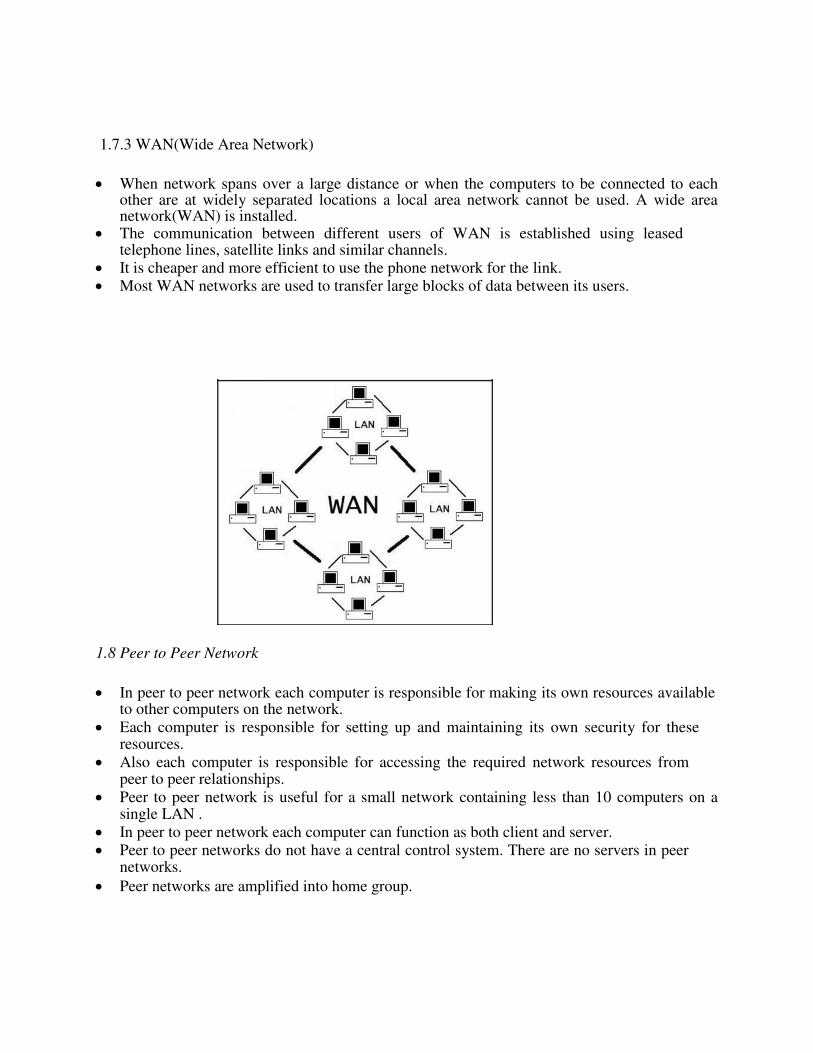
1.7.3 WAN(Wide Area Network)
When network spans over a large distance or when the computers to be connected to each other are at widely separated locations a local area network cannot be used. A wide area network(WAN) is installed.
The communication between different users of WAN is established using leased telephone lines, satellite links and similar channels.
It is cheaper and more efficient to use the phone network for the link. Most WAN networks are used to transfer large blocks of data between its users.
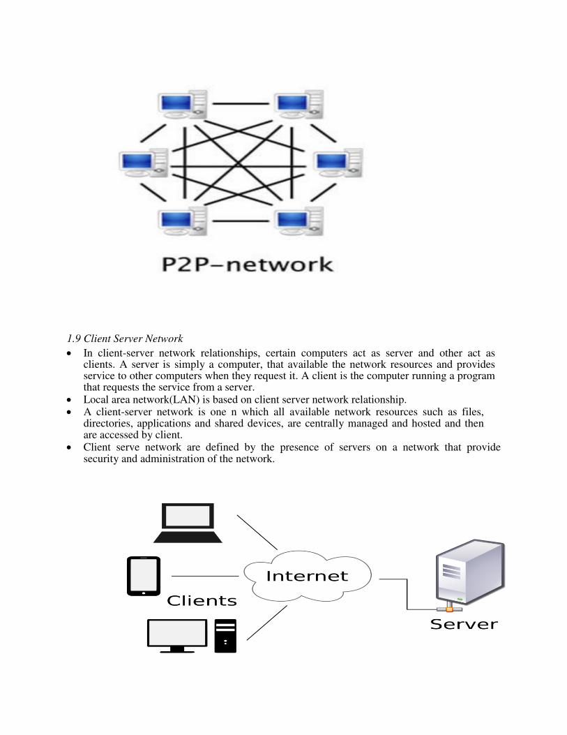
1.8 Peer to Peer Network
In peer to peer network each computer is responsible for making its own resources available to other computers on the network.
Each computer is responsible for setting up and maintaining its own security for these resources.
Also each computer is responsible for accessing the required network resources from peer to peer relationships.
Peer to peer network is useful for a small network containing less than 10 computers on a single LAN .
In peer to peer network each computer can function as both client and server. Peer to peer networks do not have a central control system. There are no servers in peer
networks.
Peer networks are amplified into home group.
1.9 Client Server Network
In client-server network relationships, certain computers act as server and other act as clients. A server is simply a computer, that available the network resources and provides service to other computers when they request it. A client is the computer running a program that requests the service from a server.
Local area network(LAN) is based on client server network relationship. A client-server network is one n which all available network resources such as files,
directories, applications and shared devices, are centrally managed and hosted and then are accessed by client.
Client serve network are defined by the presence of servers on a network that provide security and administration of the network.
1.10 Topologoies
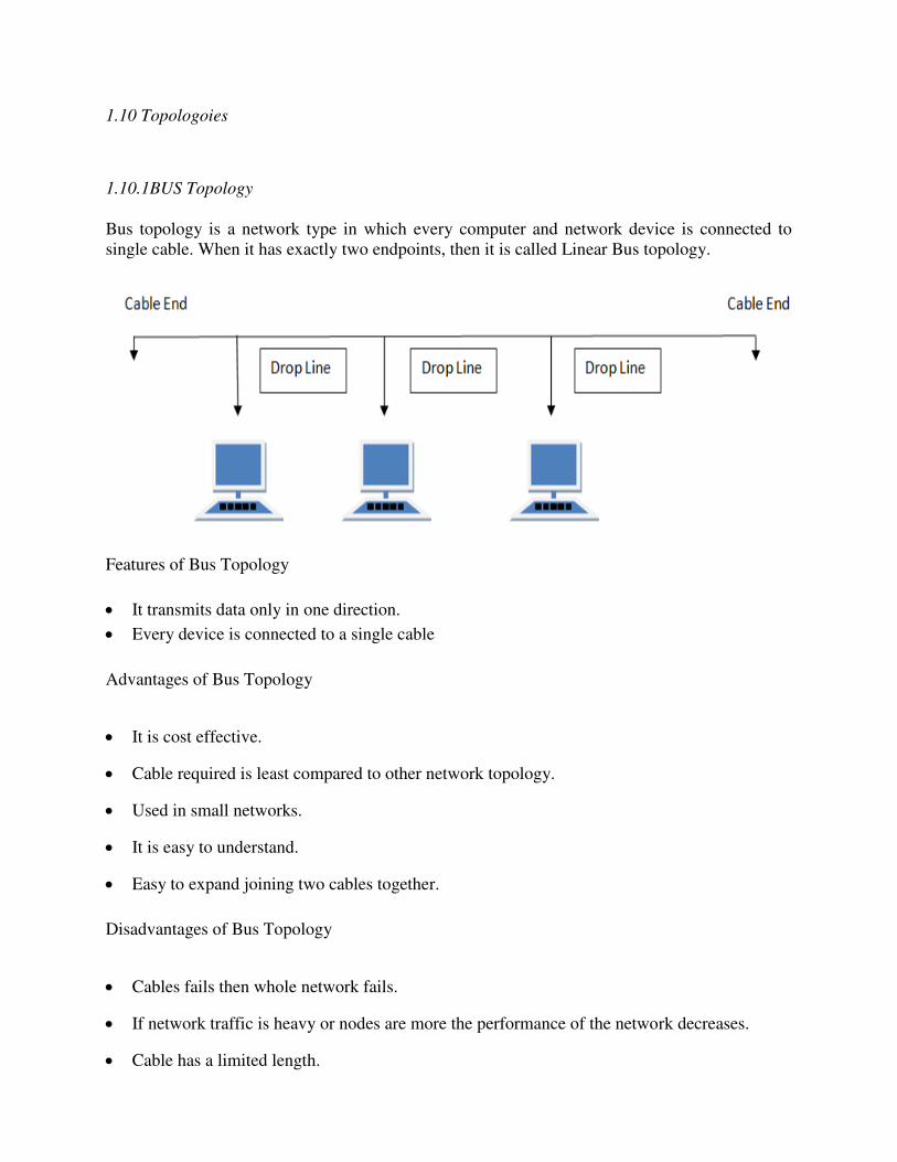
1.10.1BUS Topology
Bus topology is a network type in which every computer and network device is connected to
single cable. When it has exactly two endpoints, then it is called Linear Bus topology.
Features of Bus Topology
It transmits data only in one direction.
Every device is connected to a single cable
Advantages of Bus Topology
It is cost effective.
Cable required is least compared to other network topology.
Used in small networks.
It is easy to understand.
Easy to expand joining two cables together.
Disadvantages of Bus Topology
Cables fails then whole network fails.
If network traffic is heavy or nodes are more the performance of the network decreases.
Cable has a limited length.
It is slower than the ring topology.
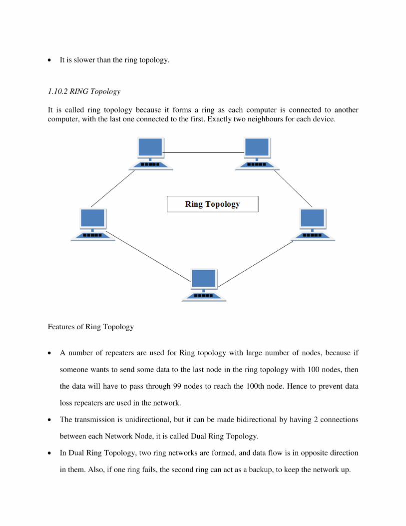
1.10.2 RING Topology
It is called ring topology because it forms a ring as each computer is connected to another
computer, with the last one connected to the first. Exactly two neighbours for each device.
Features of Ring Topology
A number of repeaters are used for Ring topology with large number of nodes, because if
someone wants to send some data to the last node in the ring topology with 100 nodes, then
the data will have to pass through 99 nodes to reach the 100th node. Hence to prevent data
loss repeaters are used in the network.
The transmission is unidirectional, but it can be made bidirectional by having 2 connections
between each Network Node, it is called Dual Ring Topology.
In Dual Ring Topology, two ring networks are formed, and data flow is in opposite direction
in them. Also, if one ring fails, the second ring can act as a backup, to keep the network up.
Data is transferred in a sequential manner that is bit by bit. Data transmitted, has to pass
through each node of the network, till the destination node.
Advantages of Ring Topology
Transmitting network is not affected by high traffic or by adding more nodes, as only the
nodes having tokens can transmit data.
Cheap to install and expand
Disadvantages of Ring Topology
Troubleshooting is difficult in ring topology.
Adding or deleting the computers disturbs the network activity.
Failure of one computer disturbs the whole network.
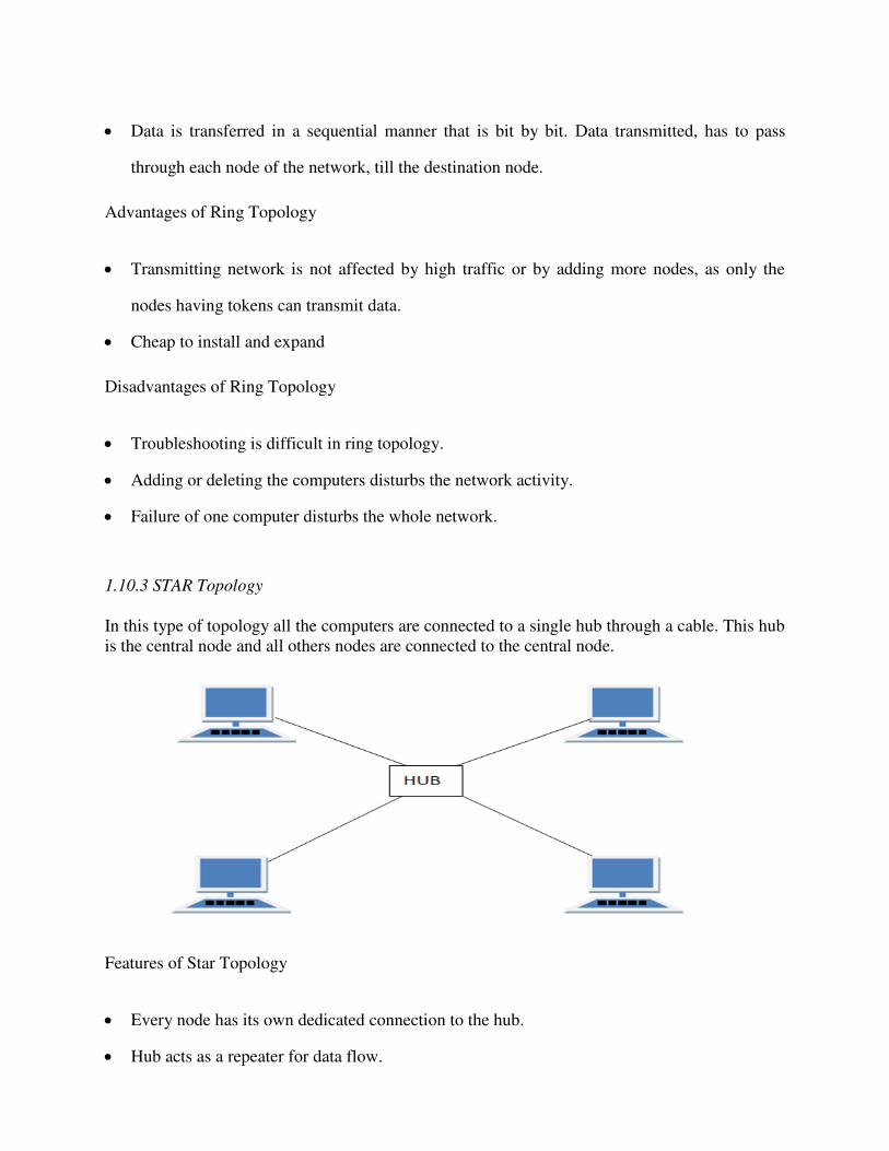
1.10.3 STAR Topology
In this type of topology all the computers are connected to a single hub through a cable. This hub
is the central node and all others nodes are connected to the central node.
Features of Star Topology
Every node has its own dedicated connection to the hub.
Hub acts as a repeater for data flow.
Can be used with twisted pair, Optical Fibre or coaxial cable.
Advantages of Star Topology
Fast performance with few nodes and low network traffic.
Hub can be upgraded easily.
Easy to troubleshoot.
Easy to setup and modify.
Only that node is affected which has failed, rest of the nodes can work smoothly.
Disadvantages of Star Topology
Cost of installation is high.
Expensive to use.
If the hub fails then the whole network is stopped because all the nodes depend on the hub.
Performance is based on the hub that is it depends on its capacity
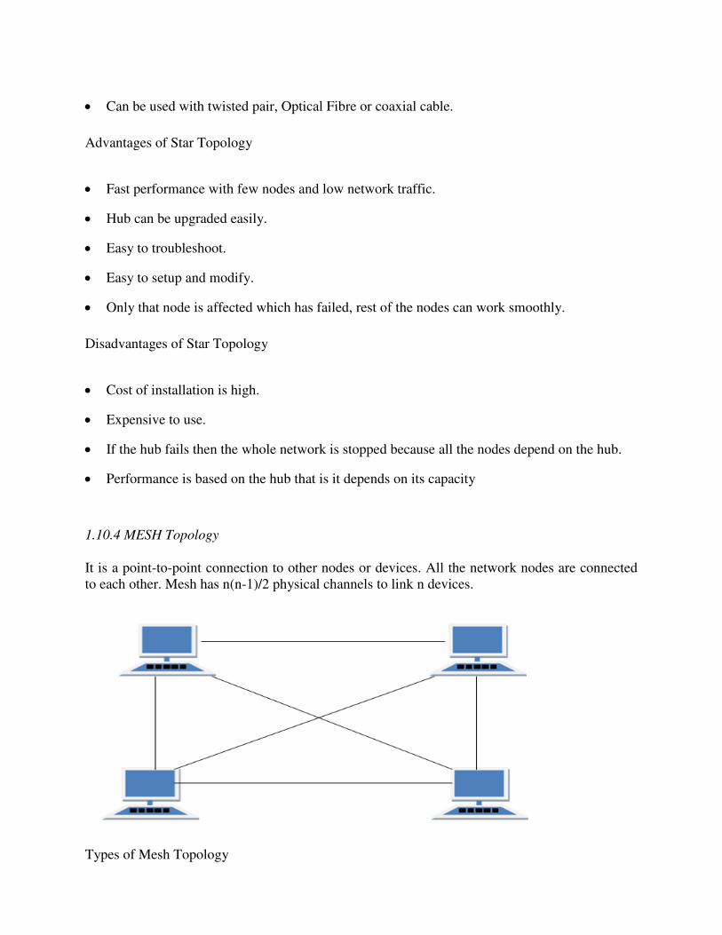
1.10.4 MESH Topology
It is a point-to-point connection to other nodes or devices. All the network nodes are connected
to each other. Mesh has n(n-1)/2 physical channels to link n devices.
Types of Mesh Topology
1. Partial Mesh Topology : In this topology some of the systems are connected in the same
fashion as mesh topology but some devices are only connected to two or three devices.
2. Full Mesh Topology : Each and every nodes or devices are connected to each other.
Features of Mesh Topology
Fully connected.
Robust.
Not flexible.
Advantages of Mesh Topology
Each connection can carry its own data load.
It is robust.
Fault is diagnosed easily.
Provides security and privacy.
Disadvantages of Mesh Topology
Installation and configuration is difficult.
Cabling cost is more.
Bulk wiring is required.
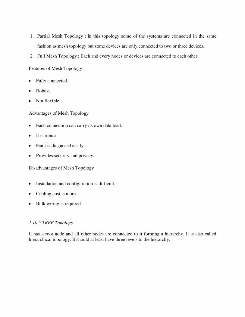
1.10.5 TREE Topology
It has a root node and all other nodes are connected to it forming a hierarchy. It is also called
hierarchical topology. It should at least have three levels to the hierarchy.
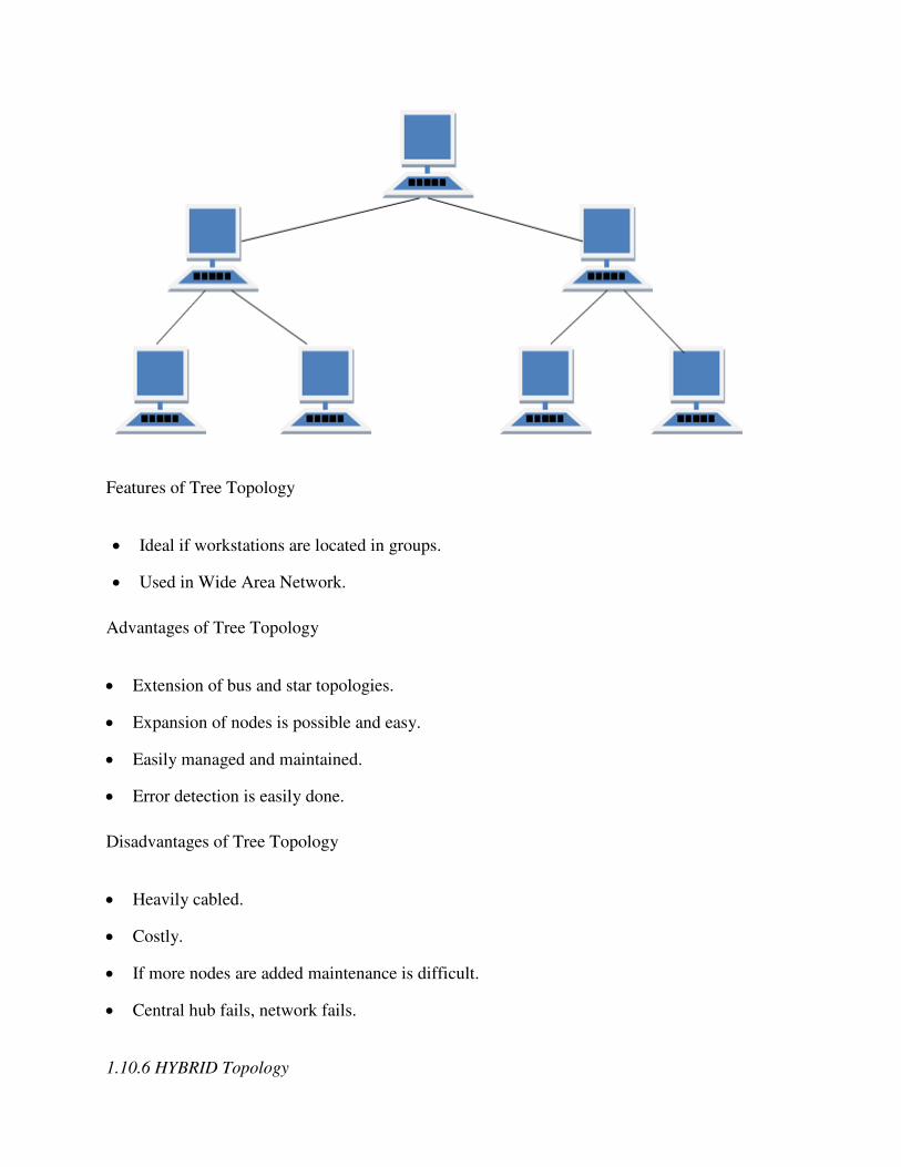
Features of Tree Topology
Ideal if workstations are located in groups.
Used in Wide Area Network.
Advantages of Tree Topology
Extension of bus and star topologies.
Expansion of nodes is possible and easy.
Easily managed and maintained.
Error detection is easily done.
Disadvantages of Tree Topology
Heavily cabled.
Costly.
If more nodes are added maintenance is difficult.
Central hub fails, network fails.
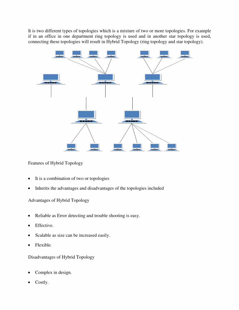
1.10.6 HYBRID Topology
It is two different types of topologies which is a mixture of two or more topologies. For example
if in an office in one department ring topology is used and in another star topology is used,
connecting these topologies will result in Hybrid Topology (ring topology and star topology).
Features of Hybrid Topology
It is a combination of two or topologies
Inherits the advantages and disadvantages of the topologies included
Advantages of Hybrid Topology
Reliable as Error detecting and trouble shooting is easy.
Effective.
Scalable as size can be increased easily.
Flexible.
Disadvantages of Hybrid Topology
Complex in design.
Costly.
1.11 Switching Techniques
1.11.1 Circuit switching: it is a technique that directly connects the sender and the receiver in
an unbroken path.
• Telephone switching equipment, for example, establishes a path that connects the caller's
telephone to the receiver's telephone by making a physical connection.
• With this type of switching technique, once a connection is established, a dedicated path
exists between both ends until the connection is terminated.
• Routing decisions must be made when the circuit is first established, but there are no decisions
made after that time
• Circuit switching in a network operates almost the same way as the telephone system works.
• A complete end-to-end path must exist before communication can take place.
• The computer initiating the data transfer must ask for a connection to the destination.
• Once the connection has been initiated and completed to the destination device, the destination
device must acknowledge that it is ready and willing to carry on a transfer.
Advantages:
• The communication channel (once established) is dedicated.
Disadvantages:
• Possible long wait to establish a connection, (10 seconds, more on long- distance or
international calls.) during which no data can be transmitted.
• More expensive than any other switching techniques, because a dedicated path is required for
each connection.
• Inefficient use of the communication channel, because the channel is not used when the
connected systems are not using it.
1.11.2 Packet Switching:
Packet Switching
• Packet switching can be seen as a solution that tries to combine the advantages of message and
circuit switching and to minimize the disadvantages of both.
• There are two methods of packet switching: Datagram and virtual circuit.
• In both packet switching methods, a message is broken into small parts, called packets.
• Each packet is tagged with appropriate source and destination addresses.
• With current technology, packets are generally accepted onto the network on a first-come, first-
served basis. If the network becomes overloaded, packets are delayed or discarded (``dropped'').
• In packet switching, the analog signal from your phone is converted into a digital data stream.
That series of digital bits is then divided into relatively tiny clusters of bits, called packets.
• Datagram packet switching is similar to message switching in that each packet is a self-
contained unit with complete addressing information attached.
• This fact allows packets to take a variety of possible paths through the network.
• So the packets, each with the same destination address, do not follow the same route, and they
may arrive out of sequence at the exit point node (or the destination).
• Reordering is done at the destination point based on the sequence number of the packets.
• It is possible for a packet to be destroyed if one of the nodes on its way is crashed momentarily.
Thus all its queued packets may be lost.
• In the virtual circuit approach, a preplanned route is established before any data packets are
sent.
• A logical connection is established when a sender send a "call request packet" to the receiver
and the receiver send back an acknowledge packet "call accepted packet" to the sender if the
receiver agrees on conversational parameters.
• The conversational parameters can be maximum packet sizes, path to be taken, and other
variables necessary to establish and maintain the conversation.
• Virtual circuits imply acknowledgements, flow control, and error control, so virtual circuits are reliable. That is, they have the capability to inform upper-protocol layers if a transmission
problem occurs
• In virtual circuit, the route between stations does not mean that this is a dedicated path, as in circuit switching.
• A packet is still buffered at each node and queued for output over a line.
Advantages:
• Packet switching is cost effective, because switching devices do not need massive amount of secondary storage.
• Packet switching offers improved delay characteristics, because there are no long messages in
the queue (maximum packet size is fixed).
• Packet can be rerouted if there is any problem, such as, busy or disabled links.
•The advantage of packet switching is that many network users can share the same channel at the
same time. Packet switching can maximize link efficiency by making optimal use of link
bandwidth.
Disadvantages:
• Protocols for packet switching are typically more complex.
• It can add some initial costs in implementation.
• If packet is lost, sender needs to retransmit the data. Another disadvantage is that packet-switched systems still can’t deliver the same quality as dedicated circuits in applications
requiring very little delay - like voice conversations or moving images.
1.11.3 Message Switching
• With message switching there is no need to establish a dedicated path between two stations.
• When a station sends a message, the destination address is appended to the message.
• The message is then transmitted through the network, in its entirety, from node to node.
• Each node receives the entire message, stores it in its entirety on disk, and then transmits the message to the next node.
• This type of network is called a store-and-forward network.
A message-switching node is typically a general-purpose computer. The device needs sufficient
secondary-storage capacity to store the incoming messages, which could be long. A time delay is
introduced using this type of scheme due to store- and-forward time, plus the time required to
find the next node in the transmission path.
Advantages:
• Channel efficiency can be greater compared to circuit-switched systems, because more
devices are sharing the channel.
• Traffic congestion can be reduced, because messages may be temporarily stored in route.
• Message priorities can be established due to store-and-forward technique.
• Message broadcasting can be achieved with the use of broadcast address appended in the
message
Disadvantages
• Message switching is not compatible with interactive applications.
• Store-and-forward devices are expensive, because they must have large disks to hold
potentially long messages
VERY SHORT QUESTIONS
1. Define network?
2. What is full form of LAN?
3. Define star topology?
4. What is a server?
5. Name various elements of computer network?
6. What are the 3 phases of circuit switching?
7. Name four network topology?
SHORT QUESTIONS
1. Explain packet switching?
2. What is message switching?
3. Explain tree and star topology?
4. Discuss mesh topology?
5. What are the uses of computer network?
6. What is peer to peer network?
7. What is Ring topology?
8. What do you mean by email?
LONG QUESTIONS
1. Explain various topologies in detail?
2. Explain switching techniques?
3. What is peer to peer and client server model?
4. What is computer network and what are its applications?
2. NETWORKING MODELS
2.1 Learning objectives
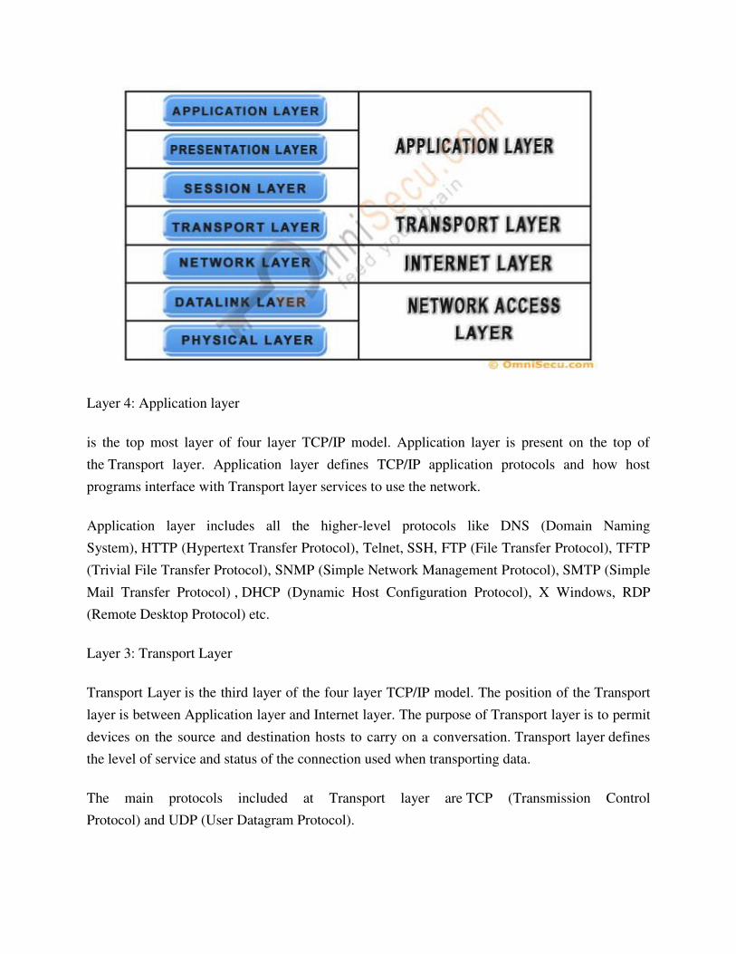
2.2 OSI model
Established in 1947, the International Standards Organization(ISO) is a multinational body
dedicated to world wide agreement on international standards .An ISO standard that covers all
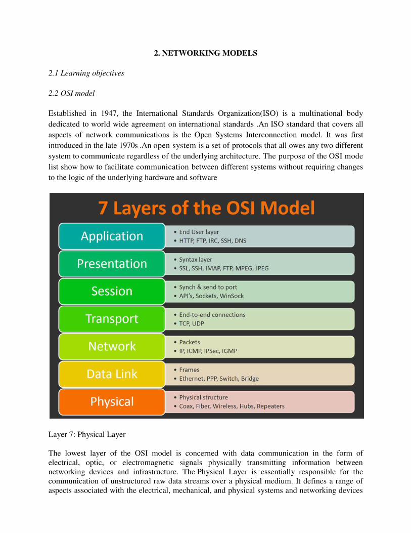
aspects of network communications is the Open Systems Interconnection model. It was first
introduced in the late 1970s .An open system is a set of protocols that all owes any two different
system to communicate regardless of the underlying architecture. The purpose of the OSI mode
list show how to facilitate communication between different systems without requiring changes
to the logic of the underlying hardware and software
Layer 7: Physical Layer
The lowest layer of the OSI model is concerned with data communication in the form of
electrical, optic, or electromagnetic signals physically transmitting information between
networking devices and infrastructure. The Physical Layer is essentially responsible for the
communication of unstructured raw data streams over a physical medium. It defines a range of
aspects associated with the electrical, mechanical, and physical systems and networking devices
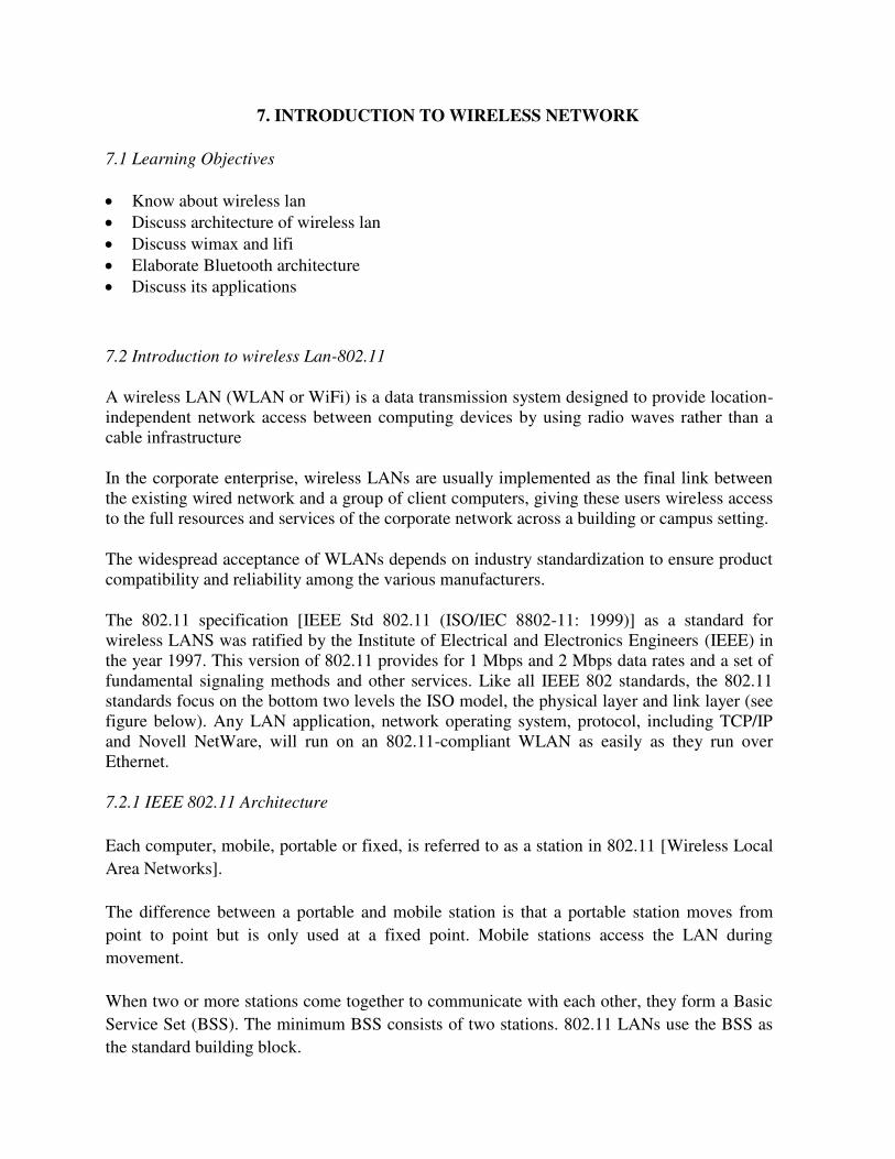
Bluetooth communication occurs between a master radio and a slave radio. Bluetooth radios are
symmetric in that the same device may operate as a master and also the slave. Each radio has a
48-bit unique device address (BD_ADDR) that is fixed.
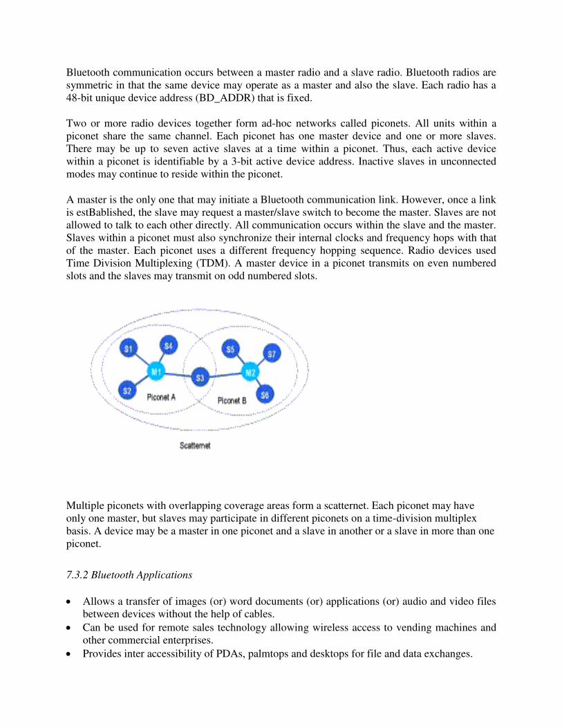
Two or more radio devices together form ad-hoc networks called piconets. All units within a
piconet share the same channel. Each piconet has one master device and one or more slaves.
There may be up to seven active slaves at a time within a piconet. Thus, each active device
within a piconet is identifiable by a 3-bit active device address. Inactive slaves in unconnected
modes may continue to reside within the piconet.
A master is the only one that may initiate a Bluetooth communication link. However, once a link
is estBablished, the slave may request a master/slave switch to become the master. Slaves are not
allowed to talk to each other directly. All communication occurs within the slave and the master.
Slaves within a piconet must also synchronize their internal clocks and frequency hops with that
of the master. Each piconet uses a different frequency hopping sequence. Radio devices used
Time Division Multiplexing (TDM). A master device in a piconet transmits on even numbered
slots and the slaves may transmit on odd numbered slots.
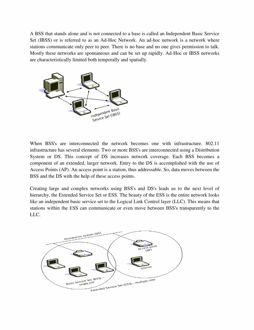
Multiple piconets with overlapping coverage areas form a scatternet. Each piconet may have
only one master, but slaves may participate in different piconets on a time-division multiplex
basis. A device may be a master in one piconet and a slave in another or a slave in more than one
piconet.
7.3.2 Bluetooth Applications
Allows a transfer of images (or) word documents (or) applications (or) audio and video files
between devices without the help of cables.
Can be used for remote sales technology allowing wireless access to vending machines and
other commercial enterprises.
Provides inter accessibility of PDAs, palmtops and desktops for file and data exchanges.
It can be used to setup a personal area network (PAN) or a wireless personal area network
(WPAN).
VERY SHORT QUESTIONS
1. what is the full form of PAN?
2. What is the full form of WPAN?
3. Which technology us used in lifi?
4. What is the full form of TDM?
5. What is the full form of WLAN?
6. What does ESS and BSS stand for?
7. What does IEEE stand for?
8. What is the IEEE specification for WLAN?
SHORT QUESTIONS
1. Discuss about WLAN in brief?
2. What is Wimax?
3. What is lifi and what are its benefits?
4. What are the applications of Bluetooth?
5. What is piconet?
LONG QUESTIONS
1. Discuss about WLAN and its architecture in detail?
2. Mention about Bluetooth architecture?
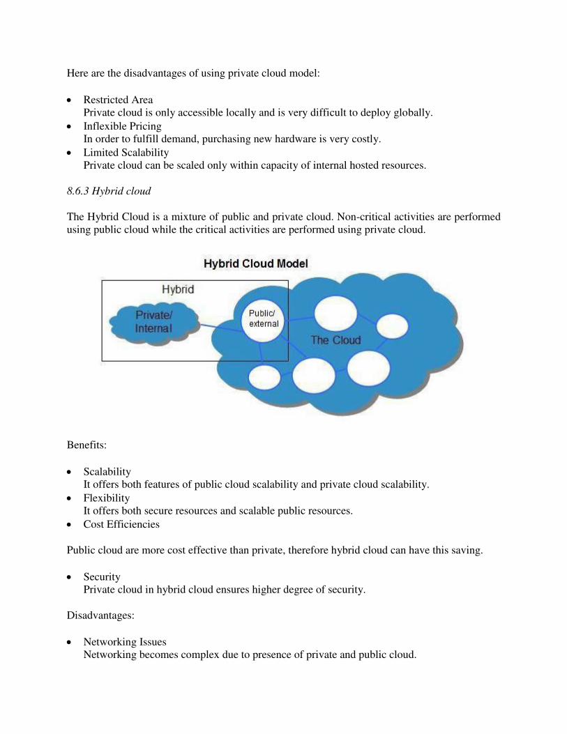
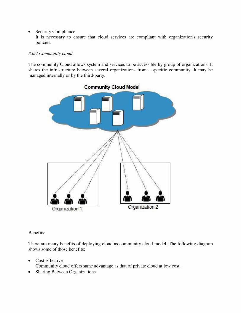
8. CLOUD COMPUTING
8.1Learning objectives
Describe cloud computing.
Know about advantages and applications of cloud computing.
Elaborate about history of cloud computing.
Know about challenges of cloud computing.
8.2 What is Cloud?
The term Cloud refers to a Network or Internet. In other words, we can say that Cloud is
something, which is present at remote location. Cloud can provide services over network, i.e.,
on public networks or on private networks, i.e., WAN, LAN or VPN. Applications such as e-
mail, web conferencing, customer relationship management (CRM), all run in cloud.
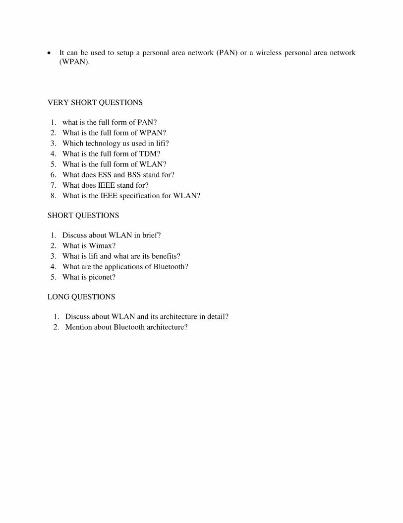
8.3 What is Cloud Computing?
Cloud Computing refers to manipulating, configuring, and accessing the applications online. It offers online data storage, infrastructure and application.
8.4 Advantages of Cloud Computing
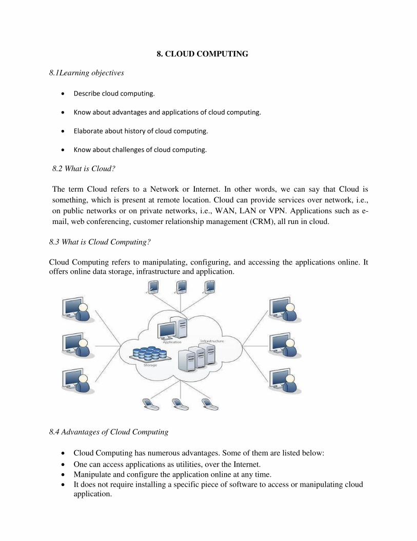
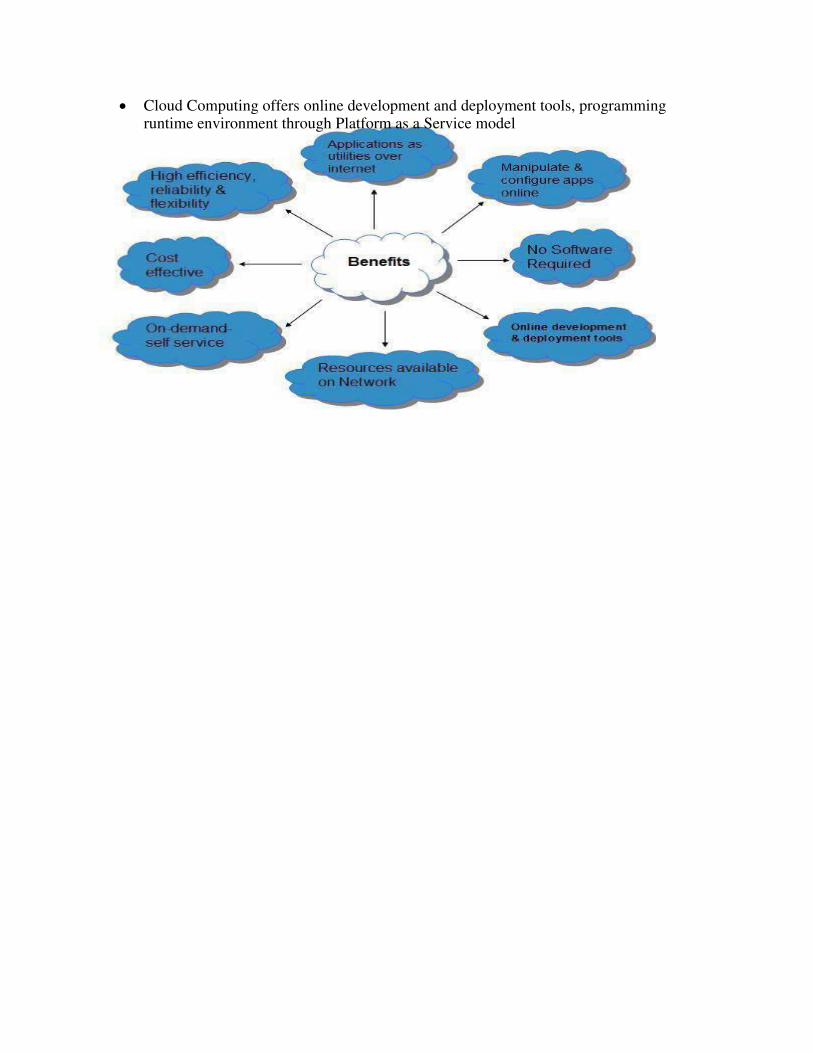
Cloud Computing has numerous advantages. Some of them are listed below:
One can access applications as utilities, over the Internet.
Manipulate and configure the application online at any time.
It does not require installing a specific piece of software to access or manipulating cloud
application.
Cloud Computing offers online development and deployment tools, programming runtime environment through Platform as a Service model
Cloud resources are available over the network in a manner that provides platform independent access to any type of clients.
Cloud Computing offers on-demand self-service. The resources can be used without interaction with cloud service provider.
Cloud Computing is highly cost effective because it operates at higher efficiencies with greater utilization. It just requires an Internet connection.
Cloud Computing offers load balancing that makes it more reliable.
8.5 SERVICE MODELS
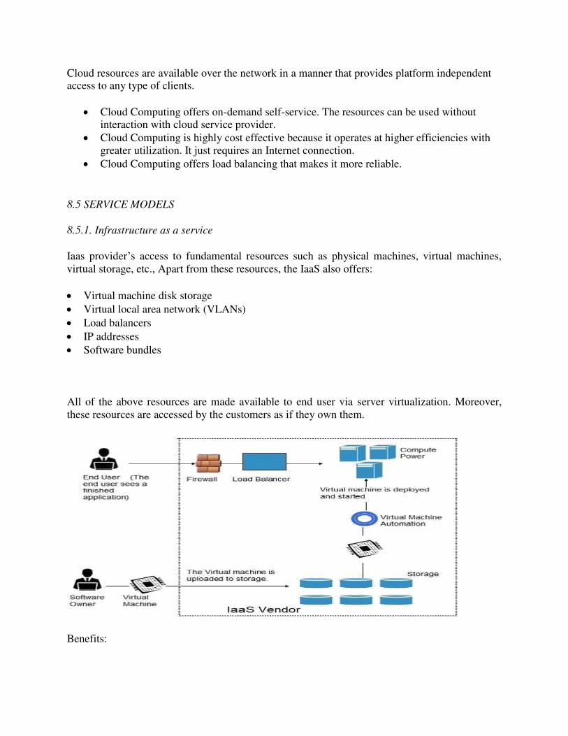
8.5.1. Infrastructure as a service
Iaas provider’s access to fundamental resources such as physical machines, virtual machines,
virtual storage, etc., Apart from these resources, the IaaS also offers:
Virtual machine disk storage
Virtual local area network (VLANs)
Load balancers
IP addresses
Software bundles
All of the above resources are made available to end user via server virtualization. Moreover,
these resources are accessed by the customers as if they own them.
Benefits:
IaaS allows the cloud provider to freely locate the infrastructure over the Internet in a cost-
effective manner. Some of the key benefits of IaaS are listed below:
Full Control of the computing resources through Administrative Access to VMs.
Flexible and Efficient renting of Computer Hardware.
Portability, Interoperability with Legacy Applications.
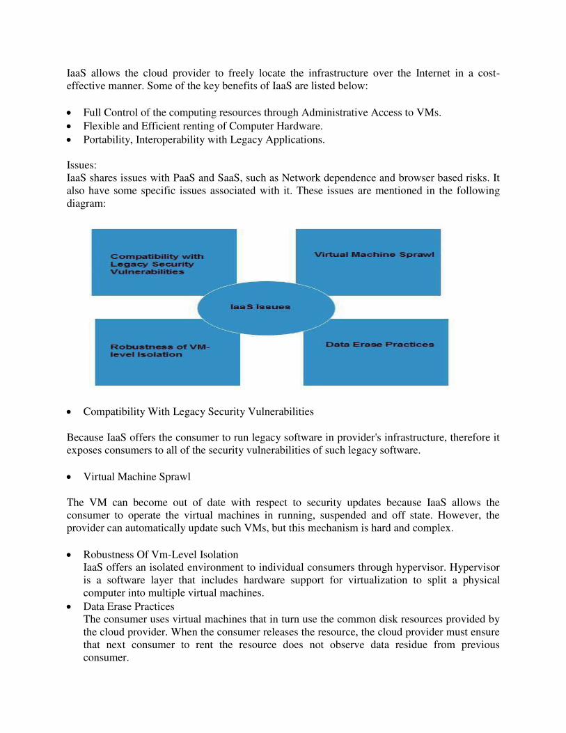
Issues:
IaaS shares issues with PaaS and SaaS, such as Network dependence and browser based risks. It
also have some specific issues associated with it. These issues are mentioned in the following
diagram:
Compatibility With Legacy Security Vulnerabilities
Because IaaS offers the consumer to run legacy software in provider's infrastructure, therefore it
exposes consumers to all of the security vulnerabilities of such legacy software.
Virtual Machine Sprawl
The VM can become out of date with respect to security updates because IaaS allows the
consumer to operate the virtual machines in running, suspended and off state. However, the
provider can automatically update such VMs, but this mechanism is hard and complex.
Robustness Of Vm-Level Isolation
IaaS offers an isolated environment to individual consumers through hypervisor. Hypervisor
is a software layer that includes hardware support for virtualization to split a physical
computer into multiple virtual machines.
Data Erase Practices
The consumer uses virtual machines that in turn use the common disk resources provided by
the cloud provider. When the consumer releases the resource, the cloud provider must ensure
that next consumer to rent the resource does not observe data residue from previous
consumer.
Characteristics:
Here are the characteristics of IaaS service model:
Virtual machines with pre-installed software.
Virtual machines with pre-installed Operating Systems such as Windows, Linux, and Solaris.
On-demand availability of resources.
Allows to store copies of particular data in different locations.
The computing resources can be easily scaled up and down.
8.5.2 Platform as a Service(PAAS)-
It also offers development & deployment tools, required to develop applications. PaaS has a
feature of point-and-click tools that enables non-developers to create web applications.Google's
App Engine, Force.com are examples of PaaS offering vendors. Developer may log on to
thesewebsites and use the built-in API to create web-based applications.
But the disadvantage of using PaaS is that the developer lock-in with a particular vendor. For
example, an application written in Python against Google's API using Google's App Engine is
likely to work only in that environment. Therefore, the vendor lock-in is the biggest problem in
PaaS.
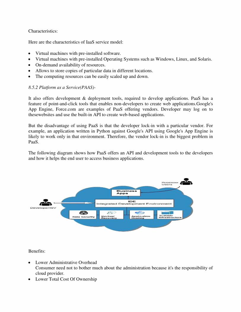
The following diagram shows how PaaS offers an API and development tools to the developers
and how it helps the end user to access business applications.
Benefits:
Lower Administrative Overhead
Consumer need not to bother much about the administration because it's the responsibility of
cloud provider.
Lower Total Cost Of Ownership
Consumer need not purchase expensive hardware, servers, power and data storage.
Scalable Solutions
It is very easy to scale up or down automatically based on application resource demands.
More Current System Softwar
It is the responsibility of the cloud provider to maintain software versions and patch
installations.
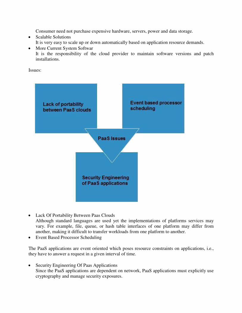
Issues:
Lack Of Portability Between Paas Clouds
Although standard languages are used yet the implementations of platforms services may
vary. For example, file, queue, or hash table interfaces of one platform may differ from
another, making it difficult to transfer workloads from one platform to another.
Event Based Processor Scheduling
The PaaS applications are event oriented which poses resource constraints on applications, i.e.,
they have to answer a request in a given interval of time.
Security Engineering Of Paas Applications
Since the PaaS applications are dependent on network, PaaS applications must explicitly use
cryptography and manage security exposures.
Characteristics:
Here are the characteristics of PaaS service model:
PaaS offers browser based development environment. It allows the developer to create
database and edit the application code either via Application Programming Interface or point-
and-click tools.
PaaS provides built-in security, scalability, and web service interfaces.
PaaS provides built-in tools for defining workflow and approval processes and defining
business rules.
It is easy to integrate with other applications on the same platform.
PaaS also provides web services interfaces that allow us to connect the applications outside
the platform.
8.5.3 Software as a Service(SaaS )
This model allows providing software application as a service to the end users. It refers to a
software that is deployed on a hosted service and is accessible via Internet. There are