45
Networking Fundamentals Chapter 1 Introducing Networks
| Date post: | 31-Dec-2015 |
| Category: |
Documents |
| Upload: | victoria-bridges |
| View: | 243 times |
| Download: | 2 times |
Networking Fundamentals
Chapter 1Introducing Networks

2
Objectives
• Identify and describe the functions of each of the seven layers of the OSI reference model
• Identify the reasons why the networking industry uses a layered model
• Define and explain the conversion steps of data encapsulation
• Define and describe the function of a MAC address• Describe connection-oriented network service and
connectionless network service, and identify the key differences between them

3
Introduction to Networking
• Computer network, or simply network– Refers to the connection of two or more computers by
some type of medium• You can connect computer using the following:
– Public telephone system– Wire cable– Fiber-optic cable– Infrared equipment– Radio equipment– Wireless Equipment
4
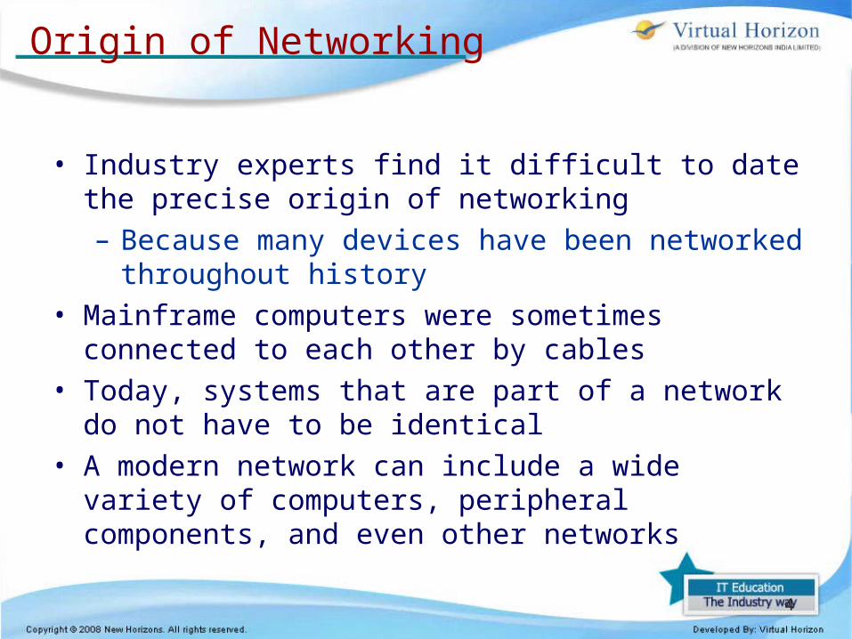
Origin of Networking
• Industry experts find it difficult to date the precise origin of networking– Because many devices have been networked
throughout history• Mainframe computers were sometimes connected to
each other by cables• Today, systems that are part of a network do not have to
be identical• A modern network can include a wide variety of
computers, peripheral components, and even other networks

5
Why Do We Use Networks?
• This question can be answered in one word: convenience– People expect interoperability from electronic devices
• Computer networks allow:– For the transfer of files, data, and even shared
applications without copying anything to floppy disk– Computers to share items such as printers, scanners,
fax machines, processors, disk drives, Video Conferencing and other resources.
• Networked computers can share data and peripherals

6
Networking Terminology
• Media– Refers to the wire cabling that form the connections in
most networks– Some networks use wireless transmission media,
such as infrared or radio signals• Client/server networks
– Servers host the resources for the clients to use and provide security
– A client is the computer that requests resources from the server
7
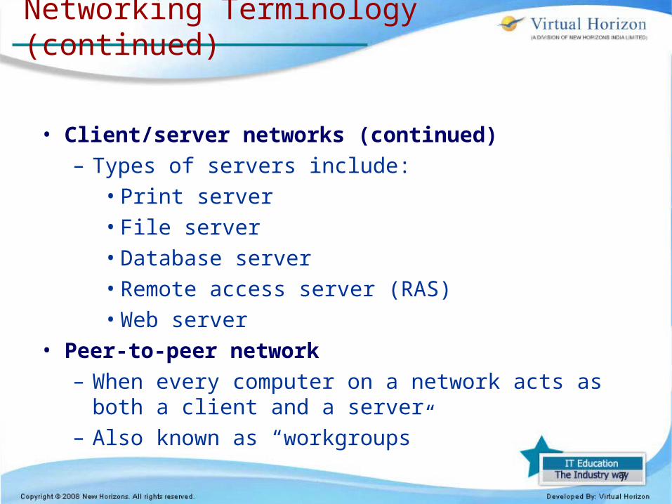
Networking Terminology (continued)
• Client/server networks (continued)– Types of servers include:
• Print server• File server• Database server• Remote access server (RAS)• Web server
• Peer-to-peer network– When every computer on a network acts as both a client
and a server– Also known as “workgroups”

8
Networking Terminology (continued)
• LAN, WAN, MAN, SAN
– Local area network (LAN) is contained within a company or department and located in a single geographic area
– Wide area network (WAN) spans multiple geographic areas and is usually connected by common telecommunication carriers
– Metropolitan area network (MAN) refers to the intermediate stage between a LAN and a WAN
9
Networking Terminology (continued)
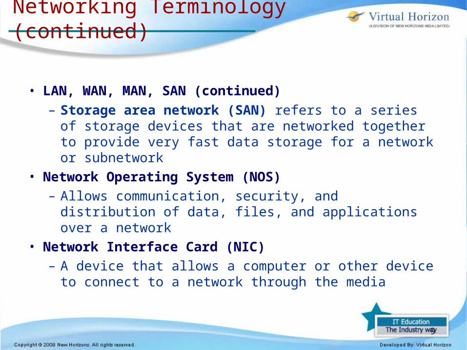
• LAN, WAN, MAN, SAN (continued)
– Storage area network (SAN) refers to a series of storage devices that are networked together to provide very fast data storage for a network or subnetwork
• Network Operating System (NOS)– Allows communication, security, and distribution of
data, files, and applications over a network• Network Interface Card (NIC)
– A device that allows a computer or other device to connect to a network through the media
10
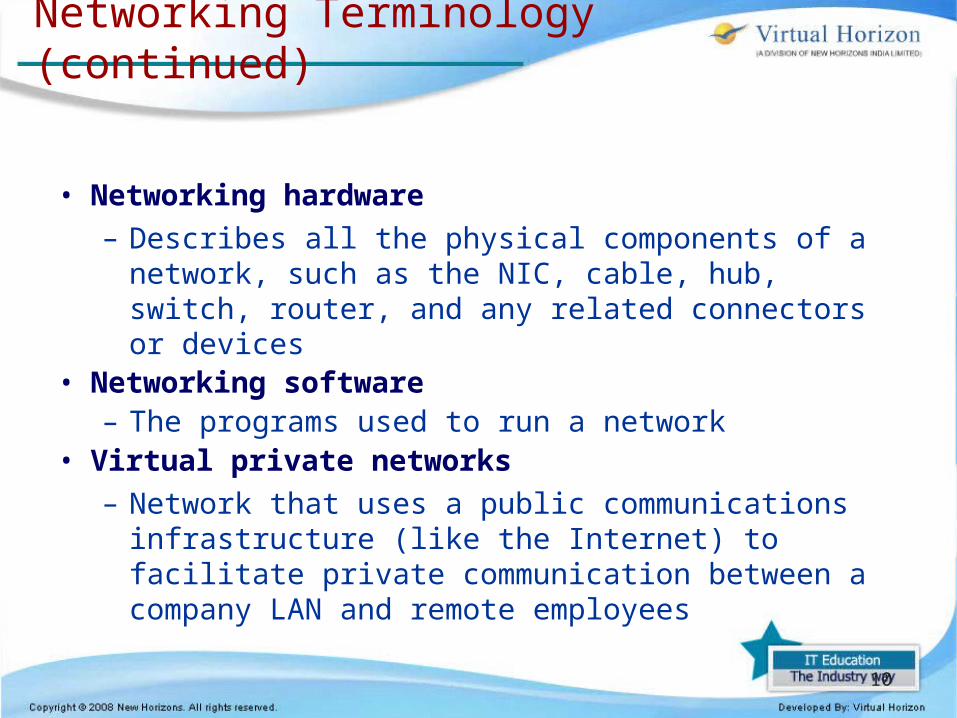
Networking Terminology (continued)
• Networking hardware
– Describes all the physical components of a network, such as the NIC, cable, hub, switch, router, and any related connectors or devices
• Networking software– The programs used to run a network
• Virtual private networks
– Network that uses a public communications infrastructure (like the Internet) to facilitate private communication between a company LAN and remote employees

11
Networking Terminology (continued)
• Virtual private networks (continued)
– Extranet is the part of the company’s network that allows access to nonemployees
– Intranet is the part of the company’s network that allows access to employees

12
Understanding the OSI Model
• Open Systems Interconnection (OSI) model– Presented in 1984 by the International Organization
for Standardization (ISO)
– Based on examination of existing protocols, ISO recommended a seven-layer network model
– Allows vendors to implement networks that permit communication among the wide variety of network implementations
• The OSI model is not an absolute standard for computer networks– Used as a reference model
13
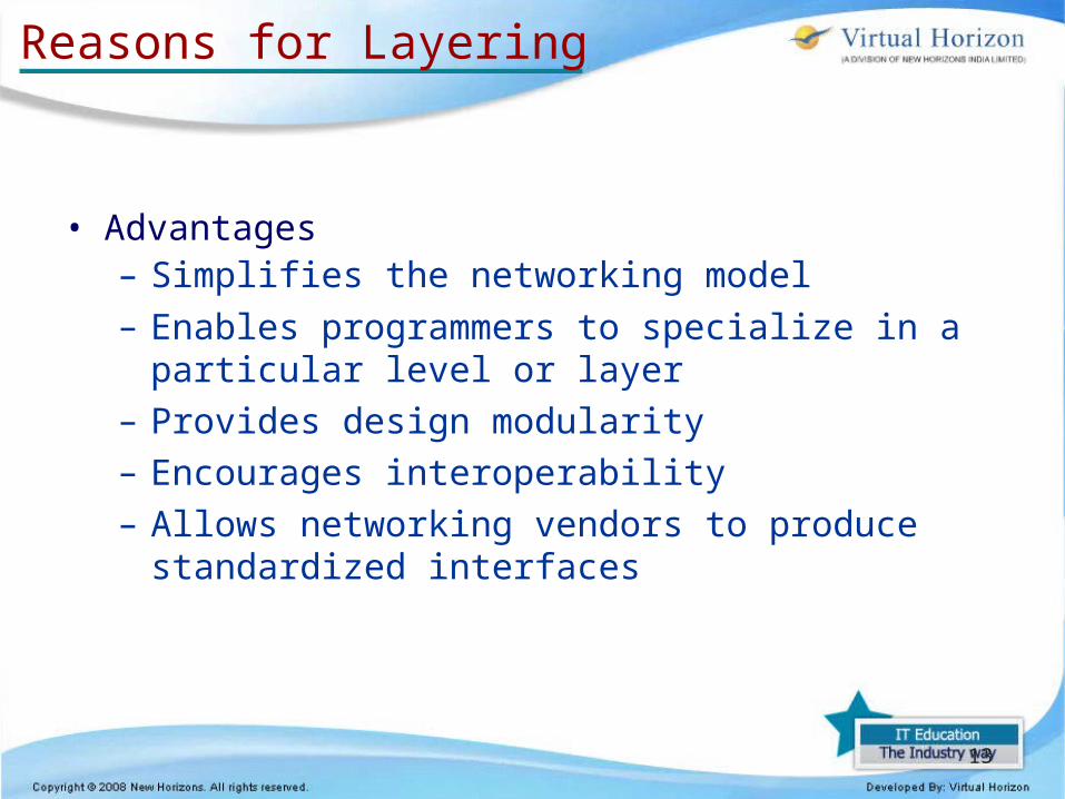
Reasons for Layering
• Advantages– Simplifies the networking model
– Enables programmers to specialize in a particular level or layer
– Provides design modularity– Encourages interoperability– Allows networking vendors to produce standardized
interfaces

14

OSI Model OverviewOSI Model Overview
Data Flow Layers
Transport Layer
Data Link
Network Layer
Physical
Application (Upper) Layers
Session
Presentation
Application
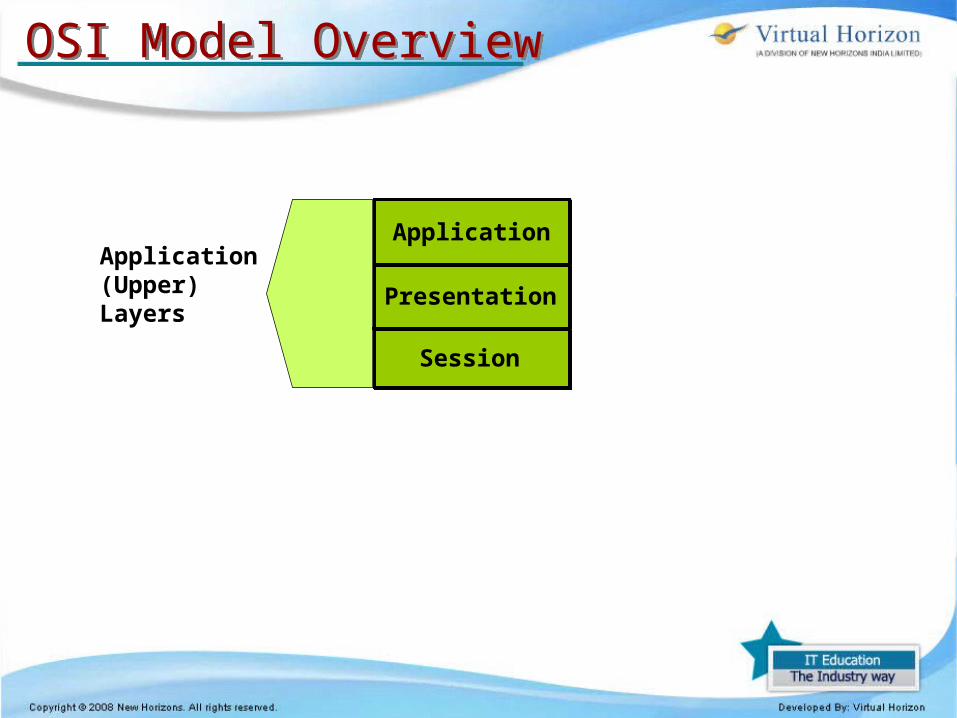
OSI Model OverviewOSI Model Overview
Application (Upper) Layers
Session
Presentation
Application

Role of Application LayersRole of Application Layers
TelnetFTP
User Interface
EXAMPLES
Application

TelnetFTP
ASCIIEBCDICJPEG
User Interface
• How data is presented• Special processing such as encryption
EXAMPLES
Presentation
Application
Role of Application LayersRole of Application Layers

TelnetFTP
ASCIIEBCDICJPEG
Keeping different applications’ data separate
User Interface
• How data is presented• Special processing such as encryption
Operating System/Application Access Scheduling
EXAMPLES
Session
Presentation
Application
Role of Application LayersRole of Application Layers
Extended Binary Coded Decimal Interchange Code
American Standard Code for Information Interchange

Keeping different applications’ data separate
User Interface
• How data is presented• Special processing such as encryption
TelnetFTP
ASCIIEBCDICJPEG
Operating System/Application Access Scheduling
Transport Layer
Data Link
Network Layer
Physical
EXAMPLES
Session
Presentation
Application
Role of Application LayersRole of Application Layers
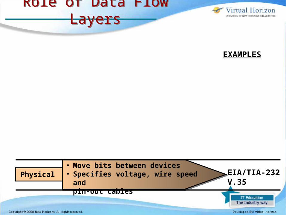
Role of Data Flow LayersRole of Data Flow Layers
EIA/TIA-232V.35
EXAMPLES
Physical • Move bits between devices• Specifies voltage, wire speed and
pin-out cables
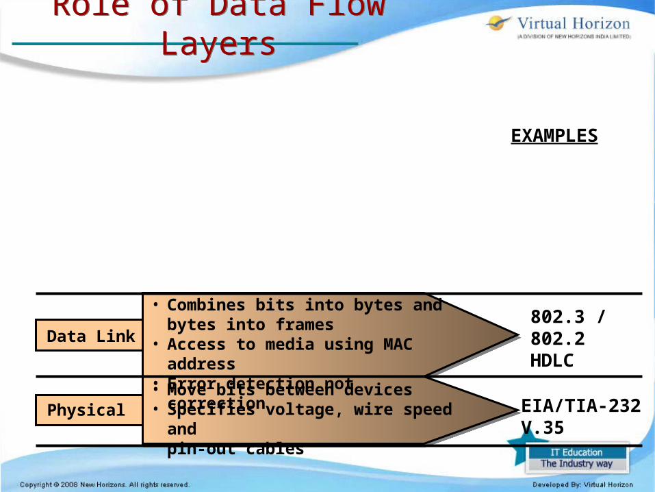
802.3 / 802.2HDLC
EIA/TIA-232V.35
EXAMPLES
Role of Data Flow LayersRole of Data Flow Layers
Data Link
Physical
• Combines bits into bytes and bytes into frames
• Access to media using MAC address• Error detection not correction
• Move bits between devices• Specifies voltage, wire speed and
pin-out cables

802.3 / 802.2HDLC
EIA/TIA-232V.35
IPIPX
EXAMPLES
Role of Data Flow LayersRole of Data Flow Layers
Network
Data Link
Physical
• Combines bits into bytes and bytes into frames
• Access to media using MAC address• Error detection not correction
• Move bits between devices• Specifies voltage, wire speed and
pin-out cables
Provide logical addressing which routers use for path determination

TCPUDPSPX
802.3 / 802.2HDLC
EIA/TIA-232V.35
IPIPX
EXAMPLES
Role of Data Flow LayersRole of Data Flow Layers
Transport
Data Link
Physical
• Reliable or unreliable delivery• Error correction before retransmit
• Combines bits into bytes and bytes into frames
• Access to media using MAC address• Error detection not correction
• Move bits between devices• Specifies voltage, wire speed and
pin-out cables
Network Provide logical addressing which routers use for path determination
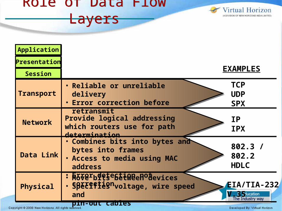
TCPUDPSPX
802.3 / 802.2HDLC
EIA/TIA-232V.35
IPIPX
Presentation
Application
SessionEXAMPLES
Role of Data Flow LayersRole of Data Flow Layers
• Reliable or unreliable delivery• Error correction before retransmit
• Combines bits into bytes and bytes into frames
• Access to media using MAC address• Error detection not correction
• Move bits between devices• Specifies voltage, wire speed and
pin-out cables
Transport
Data Link
Physical
Network Provide logical addressing which routers use for path determination
26
Reasons for Layering (continued)
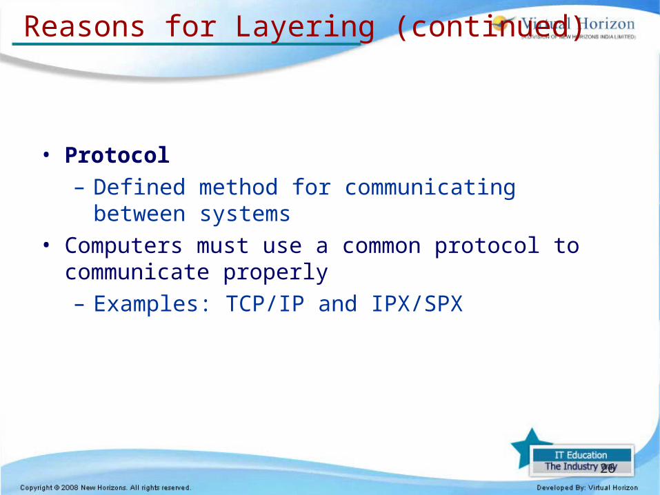
• Protocol– Defined method for communicating between systems
• Computers must use a common protocol to communicate properly– Examples: TCP/IP and IPX/SPX

27
Peer OSI Communication
• Peer communication– Each layer will only talk to its peer on the opposite
side of the communications process– Each layer is unaware of the activities of all other
layers of the model– Allows error checking to occur on two separate layers
simultaneously• Each layer does provide services to the layer above it
and receives services from the layer below it– Layers do not acknowledge these services in any way

28
Layer Functions
• The OSI model was developed as an industry standard– For companies to use when developing network
hardware and software to ensure complete compatibility
• Each layer in the OSI model performs a specific function in the transmission process
• Most modern networks do not implement the OSI model exactly as it is defined

29

30
Layer Functions (continued)
• Application (Layer 7) responsibilities– Initiating the request for network services– Providing network services to applications such as e-
mail and Web browsers• This layer is concerned with user interaction with the
computer and the network– Contains many protocols and utilities, such as telnet,
FTP, HTTP, DNS, SMTP, and SNMP

31
Layer Functions (continued)
• Presentation (Layer 6) responsibilities– Data translation– Data formatting– Data syntax restructuring– Data encryption– Data compression
• This layer also provides encryption services when data encryption is used in network communications

32
Layer Functions (continued)
• Session (Layer 5) services– Control for data exchange (full or half duplex)– Clocking or timing– Failure recovery– Initial link setup and link termination when
communications complete• The Session layer allows the transfer of a large set of
data across the network• Examples of Session layer protocols include NetBIOS,
SQL, RPC, and X-Windows
33
Layer Functions (continued)
• Transport (Layer 4) responsibilities– End-to-end, error-free transmission and delivery
between the ultimate sender and ultimate receiver– Flow control– Data segmentation into maximum transmission unit
(MTU) size– Messaging service for the Session layer
• Protocols that reside at the Transport layer can be connection-oriented or connectionless
• Data sent by a connectionless transport is called a datagram

34
Layer Functions (continued)
• Network (Layer 3) functions– Software/logical addressing for data packets, such as
IP, IPX, and AppleTalk– Data routing and connectivity– Best path selection
• Protocols at the Network layer allow computers to route packets to remote networks using a logical address
35
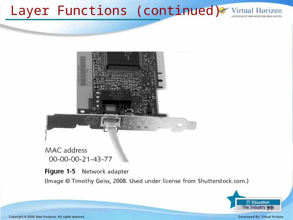
Layer Functions (continued)
• Data Link (Layer 2) responsibilities– NIC software functions, including the identification of
the source and destination nodes via their physical addresses (Media Access Control addresses)
– Definition of how data is packaged for transport in smaller units known as frames
– Error notification• The Data Link sublayers:
– Logical Link Control (LLC) layer – Media Access Control (MAC) layer

36
Layer Functions (continued)
37
Layer Functions (continued)
38
Layer Functions (continued)
• Physical (Layer 1) responsibilities– Defines the physical characteristics of the network
hardware, including cable and connectors– Represents binary digits as voltages (encoding)– Transmits signals on the wire

39
40
Layer Functions (continued)
• Data encapsulation– Data is sent from one computer to another in a data
packet– Each layer in the protocol stack may add a protocol
data unit (PDU) to the data as it is passed down the layers
– The addition of a header and/or trailer is called encapsulation

41
Layer Functions (continued)

42
Layer Functions (continued)

43
Summary
• Two or more computers connected by media form a network
• Before computers were networked, file transfers were usually conducted by users physically walking copies of data to another computer
• The ISO developed the OSI model in the mid-1980s to standardize networking models
• Data transmission can be connection-oriented or connectionless
• The OSI networking model has seven layers

44
Summary (continued)
• The Physical layer handles the physical transmission of data across the network
• The Data Link layer, the second layer of the OSI model, interacts with the networking hardware
• The Network layer supports logical addressing and routing of data packets
• The Transport layer segments data that is to be sent out on the network into MTUs
• The Session layer, the fifth layer, establishes and maintains connections between computers during data transfers

45
Summary (continued)
• The Presentation layer, the sixth layer, handles data translation, encryption, and formatting for transmission on the network or for interpretation by the Application layer
• The Application layer, the seventh and highest layer, handles the interface between the network and the user
• When the network user sends data to the network, it goes through a five-step data encapsulation process


